US7927271B2 - Endoscope tool coupling - Google Patents
Endoscope tool coupling Download PDFInfo
- Publication number
- US7927271B2 US7927271B2 US11/436,103 US43610306A US7927271B2 US 7927271 B2 US7927271 B2 US 7927271B2 US 43610306 A US43610306 A US 43610306A US 7927271 B2 US7927271 B2 US 7927271B2
- Authority
- US
- United States
- Prior art keywords
- tool
- endoscope
- coupling
- mount
- coupling body
- Prior art date
- Legal status (The legal status is an assumption and is not a legal conclusion. Google has not performed a legal analysis and makes no representation as to the accuracy of the status listed.)
- Active, expires
Links
Images


Classifications
-
- A—HUMAN NECESSITIES
- A61—MEDICAL OR VETERINARY SCIENCE; HYGIENE
- A61B—DIAGNOSIS; SURGERY; IDENTIFICATION
- A61B1/00—Instruments for performing medical examinations of the interior of cavities or tubes of the body by visual or photographical inspection, e.g. endoscopes; Illuminating arrangements therefor
- A61B1/00112—Connection or coupling means
- A61B1/00121—Connectors, fasteners and adapters, e.g. on the endoscope handle
- A61B1/00128—Connectors, fasteners and adapters, e.g. on the endoscope handle mechanical, e.g. for tubes or pipes
-
- A—HUMAN NECESSITIES
- A61—MEDICAL OR VETERINARY SCIENCE; HYGIENE
- A61B—DIAGNOSIS; SURGERY; IDENTIFICATION
- A61B10/00—Other methods or instruments for diagnosis, e.g. instruments for taking a cell sample, for biopsy, for vaccination diagnosis; Sex determination; Ovulation-period determination; Throat striking implements
- A61B10/02—Instruments for taking cell samples or for biopsy
- A61B10/04—Endoscopic instruments
-
- A—HUMAN NECESSITIES
- A61—MEDICAL OR VETERINARY SCIENCE; HYGIENE
- A61B—DIAGNOSIS; SURGERY; IDENTIFICATION
- A61B1/00—Instruments for performing medical examinations of the interior of cavities or tubes of the body by visual or photographical inspection, e.g. endoscopes; Illuminating arrangements therefor
- A61B1/012—Instruments for performing medical examinations of the interior of cavities or tubes of the body by visual or photographical inspection, e.g. endoscopes; Illuminating arrangements therefor characterised by internal passages or accessories therefor
- A61B1/018—Instruments for performing medical examinations of the interior of cavities or tubes of the body by visual or photographical inspection, e.g. endoscopes; Illuminating arrangements therefor characterised by internal passages or accessories therefor for receiving instruments
-
- A—HUMAN NECESSITIES
- A61—MEDICAL OR VETERINARY SCIENCE; HYGIENE
- A61B—DIAGNOSIS; SURGERY; IDENTIFICATION
- A61B17/00—Surgical instruments, devices or methods, e.g. tourniquets
- A61B17/34—Trocars; Puncturing needles
- A61B17/3417—Details of tips or shafts, e.g. grooves, expandable, bendable; Multiple coaxial sliding cannulas, e.g. for dilating
- A61B17/3421—Cannulas
- A61B17/3423—Access ports, e.g. toroid shape introducers for instruments or hands
-
- A—HUMAN NECESSITIES
- A61—MEDICAL OR VETERINARY SCIENCE; HYGIENE
- A61B—DIAGNOSIS; SURGERY; IDENTIFICATION
- A61B17/00—Surgical instruments, devices or methods, e.g. tourniquets
- A61B2017/00477—Coupling
-
- A—HUMAN NECESSITIES
- A61—MEDICAL OR VETERINARY SCIENCE; HYGIENE
- A61B—DIAGNOSIS; SURGERY; IDENTIFICATION
- A61B17/00—Surgical instruments, devices or methods, e.g. tourniquets
- A61B17/34—Trocars; Puncturing needles
- A61B2017/347—Locking means, e.g. for locking instrument in cannula
-
- A—HUMAN NECESSITIES
- A61—MEDICAL OR VETERINARY SCIENCE; HYGIENE
- A61B—DIAGNOSIS; SURGERY; IDENTIFICATION
- A61B90/00—Instruments, implements or accessories specially adapted for surgery or diagnosis and not covered by any of the groups A61B1/00 - A61B50/00, e.g. for luxation treatment or for protecting wound edges
- A61B90/03—Automatic limiting or abutting means, e.g. for safety
- A61B2090/033—Abutting means, stops, e.g. abutting on tissue or skin
- A61B2090/034—Abutting means, stops, e.g. abutting on tissue or skin abutting on parts of the device itself
Definitions
- the present invention relates to a coupling for mounting a surgical tool to an endoscope.
- An endoscope is a medical instrument that can be inserted into the body cavity or organ of a patient for performing various surgical procedures.
- a working or biopsy channel typically extends along the entire length of the endoscope to allow passage of various instruments and/or tools into a patient.
- Optical instruments are conventionally provided in the endoscope for illuminating and remotely viewing the body cavity or organs.
- An endoscope includes an elongated, flexible body within which extends the channels and instrumentation.
- a control handle is conventionally provided at the proximal end of the body for holding and manipulating the endoscope through the patient.
- One or more controls may be provided on the handle for operating various features of the endoscope.
- One or more ports are conventionally provided on the handle to provide access to the working or biopsy channel.
- Surgical tools may be passed through the working or biopsy channel of the endoscope and into the patient for performing a desired surgical procedure.
- a suturing device such as disclosed in U.S. Patent Application Publication US 2005/0033319, may be passed through the working channel and into the patient to place one or more stitches in tissue. The tissue may be drawn together by tightening and securing the suture that has been placed in the tissue.
- Such a procedure may be beneficial for the treatment of various gastrointestinal or bariatric conditions, including treatments for GERD and obesity.
- an endoscope tool coupling for mounting a surgical tool to an endoscope.
- the endoscope tool coupling comprises a coupling body that is constructed and arranged to be mounted to a port of the endoscope, and a tool mount that is constructed and arranged to support the surgical tool on the coupling body.
- the tool mount is adjustably supported by the coupling body and lockable in a plurality of locked positions to maintain the surgical tool in each of a plurality of positions relative to the coupling body.
- an endoscope tool coupling for mounting a surgical tool to an endoscope.
- the endoscope tool coupling comprises a coupling body that is constructed and arranged to be mounted to a port of the endoscope, and a tool mount that is constructed and arranged to support the surgical tool on the coupling body and to position a distal end of the surgical tool at a first position relative to a distal end of the endoscope.
- the tool mount cooperates with the coupling body to generate a preload for the surgical tool so as to maintain the distal end of the surgical tool at the first position.
- an apparatus comprising an endoscope including an elongated endoscope body that is insertable into a body cavity or organ, and a tool coupling.
- the endoscope body has at least one working channel that extends from a proximal end to a distal end thereof.
- the working channel is adapted to allow passage of an elongated surgical tool therethrough.
- the tool coupling is constructed and arranged to mount a surgical tool at the proximal end of the endoscope body with the surgical tool extending through the working channel.
- the tool coupling is constructed and arranged to longitudinally adjust the distal end of the surgical tool to a plurality of positions relative to the distal end of the endoscope body and to maintain the distal end of the surgical tool at each of the plurality of positions.
- a method of mounting a surgical tool to an endoscope comprises acts of (a) mounting the surgical tool to a tool coupling provided at a working channel port located at a proximal end of the endoscope; and (b) adjusting the tool coupling to position a distal end of the surgical tool at a selected position relative to a distal end of the endoscope.
- a method of mounting a surgical tool to an endoscope comprises acts of (a) mounting the surgical tool to a tool coupling provided at a working channel port located at a proximal end of the endoscope; (b) positioning a distal end of the surgical tool at a selected position relative to a distal end of the endoscope; and (c) preloading the surgical tool with the tool coupling to maintain the distal end of the surgical tool at the selected position.
- FIG. 1 is a perspective view of an endoscope tool coupling according to one illustrative embodiment shown in an unlocked configuration and detached from an endoscope;
- FIG. 2 is a perspective view of the endoscope tool coupling of FIG. 1 shown in a locked configuration and attached to the endoscope;
- FIG. 3 is an exploded perspective view of the endoscope tool coupling of FIGS. 1-2 ;
- FIG. 4 is a side elevation view of the endoscope tool coupling of FIGS. 1-3 ;
- FIG. 5 is a cross-sectional view of the endoscope tool coupling taken along section line 5 - 5 of FIG. 4 ;
- FIG. 6 is an enlarged view of the adjustment locking arrangement according to one illustrative embodiment taken along view line 6 - 6 of FIG. 5 ;
- FIG. 7 is a cross-sectional view of the exchange port tool lock according to one illustrative embodiment taken along section line 7 - 7 of FIG. 4 ;
- FIG. 8 is a proximal end view of the endoscope tool coupling of FIGS. 1-4 illustrating the exchange port tool lock in the locked position;
- FIG. 9 is the proximal end view of FIG. 8 illustrating the exchange port tool lock in the unlocked position
- FIG. 10 is a perspective view of the endoscope tool coupling of FIGS. 1-9 attached to an endoscope and employed with an endoscopic suturing device according to one illustrative embodiment
- FIG. 11 is a perspective view of an endoscope tool coupling according to another illustrative embodiment shown in a locked configuration and detached from an endoscope;
- FIG. 12 is an exploded perspective view of the proximal end of the coupling body of FIG. 11 illustrating an embodiment of a resilient end plate for accommodating a preload configuration
- FIG. 13 is a perspective view of an alignment boss according to one illustrative embodiment
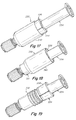
- FIG. 14 is a perspective view of an endoscope tool coupling according to another illustrative embodiment
- FIG. 15 is a cross-sectional view of the endoscope tool coupling of FIG. 14 shown in an unlocked configuration
- FIG. 16 is the cross-sectional view of FIG. 15 shown in a locked configuration
- FIG. 17 is a perspective view of an endoscope tool coupling according to another illustrative embodiment shown in an unlocked configuration
- FIG. 18 is a perspective view of the endoscope tool coupling of FIG. 17 shown in a locked configuration
- FIG. 19 is a perspective view of the endoscope tool coupling of FIGS. 17-18 shown with the locking nut removed;
- FIG. 20 is a partial perspective view of the endoscope tool coupling of FIG. 1 that includes a suture retainer according to another illustrative embodiment.
- the present invention is directed to an endoscope tool coupling that facilitates the placement and positioning of a surgical tool within an endoscope.
- the tool coupling may be configured to accommodate differences in lengths between the surgical tool and the endoscope. In this manner, the tool coupling may allow a user to precisely position and maintain the distal end of a surgical tool in a desired location relative to the distal end of the endoscope despite differences and variations in lengths.
- the tool coupling may be configured to support and lock the surgical tool in place so that a user may remove his or her hands from the surgical tool without losing the desired position of the surgical tool relative to the endoscope.
- the tool coupling may provide a hospital or medical personnel with the flexibility to readily use the same surgical tool with different length endoscopes, different length surgical tools with the same endoscope, or a combination of different length tools and different length endoscopes.
- the tool coupling may have an adjustable configuration to accommodate variations in tool and/or endoscope lengths.
- the tool coupling employs an arrangement that allows a user to easily increase or decrease the length of the coupling.
- the adjustability of the coupling length may be accomplished using a telescoping arrangement.
- a telescoping arrangement is not required for each embodiment of the coupling.
- a locking arrangement or mechanism may be provided to secure the coupling in a selected configuration for maintaining the surgical tool in a desired location relative to the endoscope.
- an adjustment lock secures the coupling in a selected length that accommodates the particular lengths of the surgical tool and endoscope.
- a locking arrangement for securing the coupling in a selected length is not required for each embodiment of the coupling.
- the tool coupling may be configured to generate a preload on the surgical tool when the tool is positioned in a desired location relative to the endoscope.
- the coupling may generate a preload by driving the surgical tool a predetermined distance in a distal direction.
- the preload may be applied once the configuration of the coupling has been established for the particular tool/endoscope arrangement.
- the tool coupling may employ a cam arrangement to generate the preload.
- an arrangement for generating a preload is not required for each embodiment of the coupling.
- the tool coupling may be configured to allow for the withdrawal and reintroduction of the same or a similar surgical tool without changing or impacting the original length adjustment and/or preload for the particular tool/endoscope arrangement.
- the tool coupling includes an exchange port that is configured to receive and lock the surgical tool to the coupling independent of the length adjustment and/or preload application.
- an exchange port is not required for each embodiment of the coupling.
- the tool coupling may be configured as a separate device that can be attached to various endoscopes. In another embodiment, the tool coupling may be an integrated component of the endoscope.
- the tool coupling may be configured for use with other medical instruments that may benefit from a device that accommodates length variations between a particular medical instrument and a surgical tool that is to be used with the instrument and/or applies a preload to the tool.
- the tool coupling is described below as a stand-alone device that can be mounted to and detached from the working port of various endoscopes. It is to be understood, however, that any one or combination of the various features of the tool coupling described below may be incorporated into an endoscope as an integral component thereof.
- the tool coupling 30 includes a coupling body 32 and a tool mount 34 that is adjustably supported at a proximal end 36 of the coupling body 32 .
- a connector 38 is provided at a distal end 40 of the coupling body 32 to mount the tool coupling to a port 42 of an endoscope 44 .
- An internal passage 46 extends through the tool mount 34 and coupling body 32 to permit insertion of a surgical tool through the tool coupling 30 and into a working channel of the endoscope 44 via the port 42 .
- the surgical tool may be supported on the proximal end of the tool mount.
- the tool mount 34 is slidably supported by the coupling body 32 in a telescoping arrangement so that the overall length of the tool coupling 30 may be selectively adjusted to accommodate variations in lengths between the surgical tool and the endoscope.
- the coupling body 32 has a generally cylindrical shape and includes a proximal end wall 48 with an opening 50 for receiving the tool mount 34 .
- the tool mount 34 includes an elongated post 52 that is configured to be inserted into and slid through the end wall opening 50 and along the length of the coupling body 32 to adjust the length of the coupling.
- the end wall opening 50 and the post 52 may be configured to have complementary shapes to help stabilize the coupling and prevent rotation of the post within the body.
- the opening and post have complementary double D shapes with curved ends and flat sides. It is to be appreciated that the end wall opening 50 and the post 52 may employ other suitable configurations as would be apparent to one of skill.
- An adjustment lock may be provided to secure the tool mount in any one of various positions relative to the coupling body.
- the adjustment lock may include at least one locking feature supported on the coupling body that is configured to engage with a corresponding locking feature provided on the tool mount.
- the adjustment lock 54 includes an engagement member 56 that is movably supported on the coupling body 32 and a locking rack 58 that extends along the post 52 of the tool mount 34 .
- the engagement member 56 includes a plurality of locking teeth 60 that engage corresponding locking teeth 62 provided on the locking rack 58 .
- the locking rack 58 is longer than the engagement member 56 to provide axial adjustment therebetween.
- the tool mount 34 may be locked in a selected position by engaging the engagement member 56 with the locking rack 58 and released for adjustment by disengaging the engagement member from the rack.
- the locking rack 58 may be configured to have a length for achieving a desired amount of total adjustment for the tool coupling. Additionally, the locking teeth 62 on the rack 58 may be spaced apart at a pitch P for achieving a desired amount of incremental adjustment. In one embodiment, the adjustment lock is configured to provide an overall length adjustment of approximately 2.0 inches with an incremental adjustment of approximately 0.075 inches. However, it is to be appreciated that the tool coupling may be configured to provide other suitable adjustments as would be apparent to one of skill in the art.
- the adjustment lock 54 may include an actuator that can be operated to lock and unlock the tool mount.
- the actuator includes a lever 64 that is pivotally supported by the coupling body 32 to actuate the engagement member 56 between a locked position and an unlocked position. With the lever 64 in a closed or locked position, as shown in FIGS. 2 and 4 - 6 , the engagement member 56 engages a portion of the locking rack 58 and locks the tool mount 34 in a selected position. Actuating the lever 64 to an open or unlocked position, as shown in FIG. 1 , disengages the engagement member 56 from the locking rack 58 to allow free axial or longitudinal movement of the tool mount 34 relative to the coupling body 32 .
- the engagement member 56 includes an engagement drum that is mounted to the lever 64 along the pivot axis 66 of the lever. In this manner, rotation R ( FIG. 2 ) of the lever 64 about the pivot axis 66 causes the engagement drum 56 to also rotate about the pivot axis 66 into and out of engagement with the locking rack 58 .
- the lever 64 and the engagement drum 56 are mounted to the coupling body 32 with an elongated pin 68 .
- the locking teeth 60 of the engagement drum 56 have a circular shape extending about the pivot axis 66 and the locking teeth 62 along the locking rack 58 have a flat shape. This arrangement helps to facilitate and maintain engagement between the engagement drum 56 and the locking rack 58 as the drum is rotated by the lever 64 .
- the teeth for the engagement drum and the locking rack may employ other configurations apparent to one of skill in the art to engage and lock the tool mount.
- the lever 64 may have a curved configuration that conforms to the shape of the coupling body 32 when the lever is placed in its closed, locked position. It is to be understood, however, that the lever may be configured to have other suitable shapes apparent to one of skill in the art.
- a preload may help ensure that the surgical tool maintains a desired position at the distal end of the endoscope, particularly when the tool is employed with a flexible endoscope and the working channel for the tool is offset from the center axis of the scope. In this manner, the preload may accommodate differences between the arc lengths of the center axis of the endoscope and the working channel that could result from bending or flexing the endoscope.
- a preload may also provide resistance to or counteract the forces required to operate the surgical tool.
- a desired preload may be generated by exerting a predetermined force on the surgical tool with the tool coupling.
- the tool coupling may generate a preload on the surgical tool by driving the tool a predetermined distance in the distal direction relative to the coupling body when the position of the distal end of the tool has been selected and locked.
- the engagement drum 56 is movable along the pin 68 in the axial direction so that axial movement 70 of the engagement drum 56 , when it is engaged with the locking rack 58 , causes the tool mount 34 to also move axially. In this manner, controlling the amount of axial movement 70 of the engagement drum 56 determines the amount of preload generated on the surgical tool.
- the engagement drum 56 includes a cam surface 72 at its proximal end that cooperates with a cam follower 74 on the coupling body 32 .
- the engagement drum 56 is driven in the distal direction due to the interaction between the cam surface 72 and the cam follower 74 .
- a spring 76 is provided at the distal end of the engagement drum 56 to bias the drum in the proximal direction so that the drum returns to its initial non-preload state when the lever actuates the engagement drum to the unlocked position ( FIG. 1 ) for releasing the tool mount.
- the cam arrangement may be configured to provide a predetermined amount of preload as the engagement drum is actuated to its locked position.
- the cam arrangement is configured to drive the locked tool mount in the distal direction approximately 0.090 inches to generate a preload on the surgical tool.
- the cam arrangement may be configured to provide other amounts of preload as would be apparent to one of skill in the art.
- the coupling body 32 includes a key 78 at its proximal end that is configured to cooperate with a corresponding keyway 80 that extends along the length of the tool mount 34 . Insertion of the tool mount 34 into the coupling body 32 requires alignment of the keyway 80 with the key 78 .
- the keying arrangement may also be configured to provide a relatively close fit to minimize rotation between the tool mount and the coupling body.
- the tool coupling may be configured to allow a user to detach a surgical tool and withdraw it from the endoscope while maintaining the selected length adjustment and/or preload.
- the same or similar tool may then be subsequently inserted through the tool coupling and positioned at the same location relative to distal end of the endoscope without having to readjust the coupling.
- some surgical procedures may require the use of several of the same or different surgical devices to perform the procedure. This could involve the introduction and removal of various surgical tools through the same working channel of the endoscope. During such a procedure, it may be beneficial to repeatedly locate the distal working end of the surgical tools at a desired location relative to the distal end of the endoscope.
- the tool coupling may include a tool exchange port that allows a user to readily exchange surgical tools without disrupting a previously set length adjustment and/or tool preload.
- the tool coupling includes a tool exchange port 82 at the proximal end of the tool mount 34 .
- the tool exchange port 82 includes a tool lock 84 that is configured to engage with and lock one or more surgical tools to the tool mount. When the tool lock 84 is released, the surgical tool may be removed from the tool coupling and withdrawn from the endoscope.
- the tool lock 84 includes a locking clip 86 located adjacent the proximal end of the tool mount at the exchange port.
- the locking clip 86 is movable between a locked position ( FIG. 8 ) to secure a tool to the tool mount and an unlocked position ( FIG. 9 ) to release the tool from the tool mount.
- the locking clip 86 is configured to slide in a transverse direction across the internal passage 46 of the tool coupling between the locked and unlocked positions.
- the locking clip 86 may be retained by a pair of pins 88 that cooperate with elongated slots 90 in the clip and an end plate 92 that overlies the locking clip at the end of the tool mount.
- the locking clip 86 includes at least one locking tooth 94 that is configured to mate with a corresponding recess (not shown) provided on the surgical tool. As shown in FIG. 8 , the locking tooth 94 protrudes into the internal passage 46 of the exchange port in an inward radial direction when the locking clip is placed in the locked position.
- the tool lock 84 may include an actuator that allows a user to move the locking clip to an unlocked position in which the locking tooth is disengaged from the tool.
- the locking clip 86 includes an actuator button 96 that is located opposite to and extends away from the locking tooth 94 .
- the actuator button 96 is configured to protrude from the side of the tool exchange port when the locking clip is in the locked position.
- the actuator button 96 is depressed 97 ( FIG. 9 ) which causes the locking clip 86 to slide and disengage the locking tooth 94 from the tool so that the tool may be removed.
- the locking clip may be biased to the locked position to ensure that the tool lock maintains a positive locking condition on the tool.
- the locking clip 86 is biased to the locked position using a spring 98 that is positioned against an end of the locking clip opposite the actuator button 96 . In this manner, when the locking clip 86 is actuated to its unlocked position, by depressing the actuator button 96 , the locking clip is driven against and deflects the spring 98 which generates a biasing force against the clip. When the actuator button 96 is released, the spring 98 urges the locking clip back to the locked position.
- a flat spring 98 may be employed to bias the locking clip 86 to the locked position. As shown, each end of the spring 98 may be retained in a slot 100 that allows the ends of the spring to move as the spring moves between a deflected and non-deflected configuration. It is to be appreciated, however, that any suitable biasing arrangement apparent to one of skill in the art may be implemented with the exchange port.
- the tool lock may be configured to automatically move from the locked position toward the unlocked position as the surgical tool is introduced through the exchange port.
- the locking tooth 94 is configured with a cam surface 102 that cooperates with the tool to drive the locking clip from its locked position.
- the locking clip 86 engages the locking recess on the tool and locks the tool to the coupling.
- a keying arrangement may be provided to ensure proper orientation and/or to prevent rotation of the surgical tool relative to the exchange port.
- the tool exchange port 82 includes one or more keys 104 at its proximal end that are configured to cooperate with corresponding keyways or other suitable features provided on the surgical tool. Insertion of the tool into the exchange port 82 can only be accomplished when the keys 104 are aligned with the corresponding features on the tool resulting in the desired orientation and/or resistance to rotation between the tool and the port.
- the tool coupling may employ other suitable locking arrangements and locking features for securing a surgical tool to the exchange port as would be apparent to one of skill in the art.
- the tool coupling may include a connector 38 at its distal end for mounting the coupling 30 to a port of the endoscope, when the coupling is not an integral component of the endoscope.
- the connector 38 includes a connector body 106 that has a plurality of resilient fingers 108 that are configured to engage and securely lock onto a port 42 of the endoscope 44 .
- the connector body 106 may be coupled to the distal end of the coupling body 32 with a connector coupler 110 .
- a connector nut 112 is threaded on the connector body 106 to secure and release the connector by tightening or loosening the connector fingers 108 about the endoscope port mount.
- the connector 38 employs a collet-like arrangement. It is to be understood, however, that other connector arrangements may be employed as would be apparent to one of skill in the art.
- the various components of the tool coupling 30 may be fabricated from any suitable materials and employing any suitable manufacturing processes apparent to one of skill in the art.
- the components may be fabricated from plastic materials, composite materials, metallic materials, and various combinations thereof.
- the coupling body 32 , the tool mount 34 , the tool mount end plate 92 and the connector body 106 may each be molded from a plastic material, such as polyetherimide.
- the engagement drum 56 may be molded from a plastic material, such as a TEFLON (fluoropolymer resin) filled acetal copolymer, and the lever 64 may be molded from a plastic material, such as an acetal copolymer.
- the locking clip 86 may be fabricated from a plastic material, such as DELRIN (acetal resin).
- the tool coupling 30 may be employed to mount a surgical tool to an endoscope to facilitate the placement and positioning of a surgical tool within an endoscope.
- the tool coupling be used to accommodate differences in lengths between the surgical tool and the endoscope.
- the tool coupling 30 is mounted to a working port of an endoscope 44 .
- a surgical tool 114 is mounted to and extends through the tool coupling 30 and along the working channel of the endoscope 44 . Positioning of the surgical tool 114 at a desired location relative to the distal end of the endoscope may be accomplished by adjusting the coupling 30 and then locking the coupling, as described above. If desired, the coupling 30 may be used to preload the tool within the endoscope, as described above.
- the surgical tool 114 is an endoscopic suturing device for endoscopically placing one or more stitches in tissue or muscle within a cavity or organ of a patient.
- the suturing device may be particularly suited for treating various gastrointestinal or bariatric conditions, such as GERD and obesity.
- the suturing device may include a suturing capsule 116 that is mounted to the distal end of the endoscope body 117 and a control handle 118 that is mounted to the tool coupling 30 at the proximal end of the endoscope.
- the control handle 118 is coupled to a suturing mechanism that is positioned within the capsule 116 . Operation of the suturing mechanism within a patient may be carried out through actuation of the control handle.
- Proper operation of the suturing device 114 may require precisely locating and securing the suturing mechanism within the capsule. This may be accomplished by inserting the suturing mechanism through the tool coupling 30 and the working port and sliding the suturing mechanism along the length of the endoscope body 117 . With the control handle 118 of the suturing device secured to the tool coupling 30 , the coupling may be adjusted in the axial direction to precisely position the suturing mechanism within the capsule 116 .
- a suture retainer may allow a user to initially exert a desired amount of tension on the suture by hand and then maintain the suture at the desired tension hands free with the suture retainer. In this manner, the user can then control and manipulate the endoscope and the suturing device using both hands, if desired, without also having to maintain suture tension by hand.
- a suture retainer 400 may be provided on the tool mount 34 to secure one or more lengths of suture 402 to the tool coupling.
- the suture retainer may be configured as a resilient clip that is attachable to the tool mount post.
- the clip includes a pair of tabs or lobes 404 that are urged together due to the resiliency of the clip. The suture may be pushed between the tabs 404 which retain the suture in place due to the opposing forces exerted by the tabs.
- the suture retainer 400 may be formed of a plastic or metallic material that provides desired resiliency and/or retention properties.
- the suture retainer includes a preformed steel clip that is overmolded with a soft polymer, such as PEBAX. If desired, the retainer may include only a steel clip.
- the suture retainer may be fabricated from other suitable material using any fabrication processes apparent to one of skill in the art.
- the suture retainer may be molded from a plastic or elastomeric material.
- the suture retainer may be fabricated as an integral feature of the tool mount.
- the tool coupling may be used to mount a surgical tool that includes an integral tool mount for mating with the coupling body.
- the surgical tool 130 includes an integral tool mount 134 that is configured to be slidable within the coupling body 132 .
- the tool mount 134 includes a locking rack 58 with a plurality of locking teeth 62 that may be engaged by the engagement drum of the coupling body 132 to lock the surgical tool 130 in any of a plurality of positions.
- the stop includes a clip 140 that is configured to be snapped onto the locking rack 58 of the tool mount 134 in close proximity to the proximal end 136 of the coupling body 132 after the surgical tool has been adjusted to its desired depth and locked to the coupling body.
- the tool can be slid into the coupling body until the clip 140 engages the end of the coupling body 132 which thereby places the tool in its desired position.
- the clip 140 may include a C-shaped body 142 that is configured to mate with a tooth 62 on the tool mount 58 and engage the end of the coupling body 132 .
- a handle 144 may be provided on the clip body 142 . It is to be appreciated that other suitable stops, if desired, may be implemented with the tool coupling as would be apparent to one of skill in the art.
- a preload may be generated by driving the tool mount 134 an additional distance in the distal direction after the desired length adjustment has been established for the particular tool and endoscope combination.
- the coupling body and/or the tool mount may be configured in a manner that accommodates the preload and reduces the effect of the clip being driven against the end wall of the coupling body.
- the coupling body 132 includes a resilient end wall 150 that is configured to allow the clip 140 to be placed against the end wall to reestablish the location of the distal end of the tool and allow the tool to be fully preloaded by driving the tool in the distal direction.
- the coupling body 132 includes an end plate 152 that is moveable in the axial direction, a spring plate 154 and a spring 156 that urges the spring plate 154 and the end plate 152 in the proximal direction.
- the end plate 152 may include a tongue or flange 158 that is configured to engage a corresponding slot or recess 160 provided in the coupling body 132 to mount and retain the resilient end wall 150 to the coupling body.
- the clip 140 similarly drives the end plate 152 in the distal direction against the biasing force of the spring 156 .
- the end plate 152 returns to its initial proximal location due to the biasing force of the spring 156 . It is to be understood that other suitable arrangements apparent to one of skill in the art may be employed to reduce potential binding between the clip and the coupling body.
- the spring 156 is configured as a wave spring formed of stainless steel flat wire.
- the spring has a spring rate of 90 lb/inch, a free length of 0.25 inches, a working height of 0.117 inches, and a load at working height of 12 lb.
- the end plate 152 may be fabricated from a plastic material, such as an acetyl copolymer, and the spring plate 154 may be fabricated from a metal, such as stainless steel.
- a plastic material such as an acetyl copolymer
- the spring plate 154 may be fabricated from a metal, such as stainless steel.
- other suitable spring configurations and materials apparent to one of skill may be employed for the components of the spring plate mechanism.
- an alignment boss 170 may be provided for attachment to the working port of the endoscope.
- the boss 170 has a cap-like configuration that corresponds to the working port 42 so that the boss can be installed over and attached to the working port.
- the boss 170 has an opening 172 which provides access to the working port of the endoscope.
- An alignment indicator may be provided on the boss 170 to provide a user with a visual reference for aligning the tool coupling with the port.
- the indicator may include an elongated recess or channel 174 which corresponds to a similar indicator 176 on the coupling body 132 .
- the indicators 174 , 176 may have a contrasting color relative to the boss 170 and the coupling body 132 so that it is easily identifiable by the user.
- the boss 170 includes one or more internal keys or fingers 178 that project into the boss opening 172 .
- the keys 178 are arranged to fit between the fingers 108 of the connector 38 to prevent rotation of the connector on the port and maintain alignment of the tool coupling with the endoscope.
- an alignment boss is not a required component of the tool coupling. It is also to be appreciated that the alignment boss, if used, may utilize other suitable configurations and features apparent to one of skill in the art to facilitate alignment of the tool coupling with the endoscope and/or maintain a particular orientation between the tool coupling and the endoscope.
- the tool coupling may employ other arrangements for adjusting and locking the tool mount relative to the coupling body. Several such adjustment and locking arrangements are illustrated in FIGS. 14-19 .
- the tool coupling 230 may employ a threaded arrangement for adjusting the tool mount 234 relative to the coupling body 232 .
- adjustment of the tool mount 234 in the axial direction may be achieved by rotating the tool mount 234 relative to the coupling body 232 . Once the desired adjustment has been achieved, the tool mount may be locked in place.
- the coupling body 232 includes an internal thread 236 along its length that cooperates with an external thread 238 along the length of the tool mount 234 .
- Rotation of the tool mount 234 either clockwise or counterclockwise causes the tool mount to move axially in either the distal or proximal directions relative to the coupling body 232 .
- a locking nut 240 may be adjusted along the length of the tool mount 234 to lock and unlock the tool mount. As shown in FIG. 15 , the tool mount 234 is unlocked by loosening the locking nut 240 so that it is spaced from the proximal end of the coupling body 232 which allows the tool mount 234 to be rotated relative to the coupling body. As shown in FIG. 16 , the tool mount 234 is locked by tightening the locking nut 240 against the proximal end of the coupling body 232 which prevents rotation of the tool mount relative to the coupling body.
- the tool coupling 330 may employ a compression-type arrangement for adjusting the tool mount relative 334 to the coupling body 332 .
- the tool mount 334 may be slid in the axial direction relative to the coupling body 332 to achieve the desired length adjustment. Once the desired adjustment has been achieved, the tool mount 334 may be locked in place by applying a compressive force against the tool mount.
- the coupling body 332 includes a split-compression tube 336 through which the tool mount 334 may be slid axially in the distal and proximal directions to make desired length adjustments.
- the compression tube 336 includes a plurality of compression members 338 that may be flexed inwardly to engage and lock the tool mount.
- a locking nut 340 is threaded on the coupling body 332 and may be adjusted in the proximal direction to lock the tool mount 334 and in the distal direction to release the tool mount.
- the tool mount 334 is unlocked when the locking nut 340 is loosened toward the distal end of the coupling body 332 which allows the compression members 338 to expand in an outward radial direction away from the tool mount.
- the tool mount 334 is locked by tightening the locking nut 340 toward the proximal end of the coupling body 332 and over the compression members 338 which compresses the tube 336 against the tool mount 334 with sufficient force to prevent movement of the tool mount relative to the coupling body.
Abstract
Description
Claims (52)
Priority Applications (2)
| Application Number | Priority Date | Filing Date | Title |
|---|---|---|---|
| US11/436,103 US7927271B2 (en) | 2006-05-17 | 2006-05-17 | Endoscope tool coupling |
| PCT/US2007/011670 WO2007136630A2 (en) | 2006-05-17 | 2007-05-16 | Endoscope tool coupling |
Applications Claiming Priority (1)
| Application Number | Priority Date | Filing Date | Title |
|---|---|---|---|
| US11/436,103 US7927271B2 (en) | 2006-05-17 | 2006-05-17 | Endoscope tool coupling |
Publications (2)
| Publication Number | Publication Date |
|---|---|
| US20070270640A1 US20070270640A1 (en) | 2007-11-22 |
| US7927271B2 true US7927271B2 (en) | 2011-04-19 |
Family
ID=38535650
Family Applications (1)
| Application Number | Title | Priority Date | Filing Date |
|---|---|---|---|
| US11/436,103 Active 2029-07-27 US7927271B2 (en) | 2006-05-17 | 2006-05-17 | Endoscope tool coupling |
Country Status (2)
| Country | Link |
|---|---|
| US (1) | US7927271B2 (en) |
| WO (1) | WO2007136630A2 (en) |
Cited By (66)
| Publication number | Priority date | Publication date | Assignee | Title |
|---|---|---|---|---|
| US20070167682A1 (en) * | 2004-04-21 | 2007-07-19 | Acclarent, Inc. | Endoscopic methods and devices for transnasal procedures |
| US20080281156A1 (en) * | 2004-04-21 | 2008-11-13 | Acclarent, Inc. | Methods and Apparatus for Treating Disorders of the Ear Nose and Throat |
| US20080319266A1 (en) * | 2007-06-19 | 2008-12-25 | Minimally Invasive Devices, Llc | Device for maintaining visualization with surgical scopes |
| US20100022826A1 (en) * | 2008-07-22 | 2010-01-28 | Fujifilm Corporation | Endoscopically inserting surgical tool |
| US20100168520A1 (en) * | 2007-06-19 | 2010-07-01 | Minimally Invasive Devices, Llc | View optimizer and stabilizer for use with surgical scopes |
| US8425505B2 (en) | 2007-02-15 | 2013-04-23 | Ethicon Endo-Surgery, Inc. | Electroporation ablation apparatus, system, and method |
| US8496574B2 (en) | 2009-12-17 | 2013-07-30 | Ethicon Endo-Surgery, Inc. | Selectively positionable camera for surgical guide tube assembly |
| US8506564B2 (en) | 2009-12-18 | 2013-08-13 | Ethicon Endo-Surgery, Inc. | Surgical instrument comprising an electrode |
| US8579897B2 (en) | 2007-11-21 | 2013-11-12 | Ethicon Endo-Surgery, Inc. | Bipolar forceps |
| US8608652B2 (en) | 2009-11-05 | 2013-12-17 | Ethicon Endo-Surgery, Inc. | Vaginal entry surgical devices, kit, system, and method |
| US20140025071A1 (en) * | 2012-05-01 | 2014-01-23 | Covidien Lp | Simplified spring load mechanism for delivering shaft force of a surgical instrument |
| US20140088432A1 (en) * | 2012-09-25 | 2014-03-27 | Boston Scientific Scimed, Inc. | Biopsy Channel Attachment Adaptor |
| US8771260B2 (en) | 2008-05-30 | 2014-07-08 | Ethicon Endo-Surgery, Inc. | Actuating and articulating surgical device |
| US8906035B2 (en) | 2008-06-04 | 2014-12-09 | Ethicon Endo-Surgery, Inc. | Endoscopic drop off bag |
| US8939897B2 (en) | 2007-10-31 | 2015-01-27 | Ethicon Endo-Surgery, Inc. | Methods for closing a gastrotomy |
| US9005198B2 (en) | 2010-01-29 | 2015-04-14 | Ethicon Endo-Surgery, Inc. | Surgical instrument comprising an electrode |
| US9011431B2 (en) | 2009-01-12 | 2015-04-21 | Ethicon Endo-Surgery, Inc. | Electrical ablation devices |
| US9028483B2 (en) | 2009-12-18 | 2015-05-12 | Ethicon Endo-Surgery, Inc. | Surgical instrument comprising an electrode |
| US9078562B2 (en) | 2010-01-11 | 2015-07-14 | Minimally Invasive Devices, Inc. | Systems and methods for optimizing and maintaining visualization of a surgical field during the use of surgical scopes |
| US9078662B2 (en) | 2012-07-03 | 2015-07-14 | Ethicon Endo-Surgery, Inc. | Endoscopic cap electrode and method for using the same |
| US9211059B2 (en) | 2007-06-19 | 2015-12-15 | Minimally Invasive Devices, Inc. | Systems and methods for optimizing and maintaining visualization of a surgical field during the use of surgical scopes |
| US9220879B2 (en) | 2004-04-21 | 2015-12-29 | Acclarent, Inc. | Devices, systems and methods useable for treating sinusitis |
| US9220526B2 (en) | 2008-11-25 | 2015-12-29 | Ethicon Endo-Surgery, Inc. | Rotational coupling device for surgical instrument with flexible actuators |
| US9233241B2 (en) | 2011-02-28 | 2016-01-12 | Ethicon Endo-Surgery, Inc. | Electrical ablation devices and methods |
| US9241834B2 (en) | 2004-04-21 | 2016-01-26 | Acclarent, Inc. | Devices, systems and methods for treating disorders of the ear, nose and throat |
| US9254169B2 (en) | 2011-02-28 | 2016-02-09 | Ethicon Endo-Surgery, Inc. | Electrical ablation devices and methods |
| US9265581B2 (en) | 2013-04-21 | 2016-02-23 | Gyrus Acmi, Inc. | Relay based tool control |
| US9277957B2 (en) | 2012-08-15 | 2016-03-08 | Ethicon Endo-Surgery, Inc. | Electrosurgical devices and methods |
| US9314620B2 (en) | 2011-02-28 | 2016-04-19 | Ethicon Endo-Surgery, Inc. | Electrical ablation devices and methods |
| US9345386B1 (en) * | 2014-11-24 | 2016-05-24 | Gyrus Acmi, Inc. | Adjustable endoscope sheath |
| US20160166330A1 (en) * | 2014-12-03 | 2016-06-16 | Cook Medical Technologies Llc | Eus fiducial needle stylet handle assembly |
| US9427255B2 (en) | 2012-05-14 | 2016-08-30 | Ethicon Endo-Surgery, Inc. | Apparatus for introducing a steerable camera assembly into a patient |
| US9522017B2 (en) | 2010-12-03 | 2016-12-20 | Minimally Invasive Devices, Inc. | Devices, systems, and methods for performing endoscopic surgical procedures |
| US9545290B2 (en) | 2012-07-30 | 2017-01-17 | Ethicon Endo-Surgery, Inc. | Needle probe guide |
| US9572623B2 (en) | 2012-08-02 | 2017-02-21 | Ethicon Endo-Surgery, Inc. | Reusable electrode and disposable sheath |
| US9597463B2 (en) | 2013-03-14 | 2017-03-21 | Boston Scientific Scimed, Inc. | Injection devices with controllable depth adjustability and methods of use |
| US20170079546A1 (en) * | 2015-09-23 | 2017-03-23 | Covidien Lp | Method of manufacturing an elongated catheter having sensor and an extended working channel |
| US9603510B2 (en) | 2011-05-17 | 2017-03-28 | Mario Ammirati | Method and apparatus for delivering an endoscope via microsurgical instruments while performing microscopic surgery |
| US9610428B2 (en) | 2004-04-21 | 2017-04-04 | Acclarent, Inc. | Devices, systems and methods useable for treating frontal sinusitis |
| US9649477B2 (en) | 2004-04-21 | 2017-05-16 | Acclarent, Inc. | Frontal sinus spacer |
| US9700326B2 (en) | 2004-04-21 | 2017-07-11 | Acclarent, Inc. | Shapeable guide catheters and related methods |
| US9826999B2 (en) | 2004-04-21 | 2017-11-28 | Acclarent, Inc. | Methods and apparatus for treating disorders of the ear nose and throat |
| US9883910B2 (en) | 2011-03-17 | 2018-02-06 | Eticon Endo-Surgery, Inc. | Hand held surgical device for manipulating an internal magnet assembly within a patient |
| US10092291B2 (en) | 2011-01-25 | 2018-10-09 | Ethicon Endo-Surgery, Inc. | Surgical instrument with selectively rigidizable features |
| US10098652B2 (en) | 2004-04-21 | 2018-10-16 | Acclarent, Inc. | Systems and methods for transnasal dilation of passageways in the ear, nose or throat |
| US10098527B2 (en) | 2013-02-27 | 2018-10-16 | Ethidcon Endo-Surgery, Inc. | System for performing a minimally invasive surgical procedure |
| US10105141B2 (en) | 2008-07-14 | 2018-10-23 | Ethicon Endo-Surgery, Inc. | Tissue apposition clip application methods |
| US10124154B2 (en) | 2005-06-10 | 2018-11-13 | Acclarent, Inc. | Catheters with non-removable guide members useable for treatment of sinusitis |
| US20190008363A1 (en) * | 2014-12-15 | 2019-01-10 | GYRUS ACMI, INC., d/b/a Olympus Surgical Technologies America | Control of a basket retrieval device |
| US10188413B1 (en) | 2004-04-21 | 2019-01-29 | Acclarent, Inc. | Deflectable guide catheters and related methods |
| US20190059941A1 (en) * | 2017-08-23 | 2019-02-28 | Memic Innovative Surgery Ltd. | Tools and methods for vaginal access |
| US10314649B2 (en) | 2012-08-02 | 2019-06-11 | Ethicon Endo-Surgery, Inc. | Flexible expandable electrode and method of intraluminal delivery of pulsed power |
| US10398292B2 (en) | 2013-03-14 | 2019-09-03 | Floshield, Inc. | Fluid dispensing control systems and methods |
| US10492810B2 (en) | 2004-04-21 | 2019-12-03 | Acclarent, Inc. | Devices, systems and methods for diagnosing and treating sinusitis and other disorders of the ears, nose and/or throat |
| USD882076S1 (en) | 2018-04-06 | 2020-04-21 | Hoya Corporation | Adjustable lock |
| US10631756B2 (en) | 2004-04-21 | 2020-04-28 | Acclarent, Inc. | Guidewires for performing image guided procedures |
| USD888234S1 (en) | 2018-04-06 | 2020-06-23 | Hoya Corporation | Locking sleeve |
| US10687911B2 (en) | 2011-12-05 | 2020-06-23 | Koninklijke Philips N.V. | Positioning and orientation of surgical tools during patient specific port placement |
| US10709315B2 (en) | 2017-04-28 | 2020-07-14 | Hoya Corporation | Apparatuses and methods for endoscopic connection |
| US10779882B2 (en) | 2009-10-28 | 2020-09-22 | Ethicon Endo-Surgery, Inc. | Electrical ablation devices |
| US10874838B2 (en) | 2004-04-21 | 2020-12-29 | Acclarent, Inc. | Systems and methods for transnasal dilation of passageways in the ear, nose or throat |
| US11065061B2 (en) | 2004-04-21 | 2021-07-20 | Acclarent, Inc. | Systems and methods for performing image guided procedures within the ear, nose, throat and paranasal sinuses |
| US11298122B2 (en) | 2018-06-07 | 2022-04-12 | EnVision Endoscopy, Inc. | Endoscopic suturing device with circular needle |
| US11529502B2 (en) | 2004-04-21 | 2022-12-20 | Acclarent, Inc. | Apparatus and methods for dilating and modifying ostia of paranasal sinuses and other intranasal or paranasal structures |
| US11534158B2 (en) | 2020-10-23 | 2022-12-27 | EnVision Endoscopy, Inc. | Endoscopic suture cinch |
| US11957318B2 (en) | 2021-04-29 | 2024-04-16 | Acclarent, Inc. | Methods and apparatus for treating disorders of the ear nose and throat |
Families Citing this family (42)
| Publication number | Priority date | Publication date | Assignee | Title |
|---|---|---|---|---|
| US9289112B2 (en) * | 2006-01-13 | 2016-03-22 | Olympus Corporation | Medical treatment endoscope having an operation stick formed to allow a procedure instrument to pass |
| US8439828B2 (en) | 2006-01-13 | 2013-05-14 | Olympus Medical Systems Corp. | Treatment endoscope |
| US9308049B2 (en) * | 2006-01-13 | 2016-04-12 | Olympus Corporation | Medical treatment endoscope |
| US8556805B2 (en) * | 2006-01-13 | 2013-10-15 | Olympus Medical Systems Corp. | Rotational force transmission mechanism, force-attenuating apparatus, medical device, and medical instrument-operation mechanism |
| US9173550B2 (en) * | 2006-01-13 | 2015-11-03 | Olympus Corporation | Medical apparatus |
| US8617054B2 (en) * | 2006-01-13 | 2013-12-31 | Olympus Medical Systems Corp. | Medical treatment endoscope |
| US9486238B2 (en) * | 2006-03-13 | 2016-11-08 | Teleflex Medical Incorporated | Minimally invasive surgical clamps, assemblies and methods |
| US7766937B2 (en) * | 2006-03-13 | 2010-08-03 | Mini-Lap Technologies, Inc. | Minimally invasive surgical assembly and methods |
| DE102007030310A1 (en) * | 2007-06-29 | 2009-01-02 | Karl Storz Gmbh & Co.Kg | Coupling device for fixing medical instruments to a holding device |
| US8758225B2 (en) * | 2007-07-26 | 2014-06-24 | Biolitec Pharma Marketing Ltd | Adapter for endoscopes and related method |
| CA2713691A1 (en) * | 2008-02-05 | 2009-08-13 | Cook Ireland Ltd. | Adaptor for endoscopic orientation of an elongate medical device |
| CN102256534B (en) * | 2008-10-20 | 2016-03-30 | 智能医疗系统有限公司 | The assembly used in endoscope and application thereof |
| US20100191050A1 (en) * | 2009-01-23 | 2010-07-29 | Ethicon Endo-Surgery, Inc. | Variable length accessory for guiding a flexible endoscopic tool |
| EP2384779B1 (en) * | 2009-03-18 | 2014-05-07 | Unisis Corp. | Anesthetic compound needle |
| WO2010110043A1 (en) * | 2009-03-25 | 2010-09-30 | テルモ株式会社 | Balloon catheter and balloon cathter assembly |
| JP5409898B2 (en) * | 2009-04-29 | 2014-02-05 | クック メディカル テクノロジーズ エルエルシー | Endoscope adapter |
| CA2757870C (en) * | 2009-04-30 | 2016-02-02 | Cook Medical Technologies Llc | System and method for fiducial deployment |
| KR20150135533A (en) * | 2009-11-06 | 2015-12-02 | 니코 코포레이션 | Surgical adapter for use with an endoscope |
| US9072542B2 (en) * | 2009-12-18 | 2015-07-07 | Cook Medical Technologies Llc | System and method for fiducial deployment |
| AU2010332069B2 (en) * | 2009-12-18 | 2013-10-17 | Cook Medical Technologies Llc | System and method for fiducial deployment |
| US9326757B2 (en) | 2009-12-31 | 2016-05-03 | Teleflex Medical Incorporated | Surgical instruments for laparoscopic aspiration and retraction |
| DE102010010798A1 (en) | 2010-03-09 | 2011-09-15 | Epflex Feinwerktechnik Gmbh | Hand-operated functional hose instrument and operating device therefor |
| DE102010013309A1 (en) | 2010-03-29 | 2011-09-29 | Karl Storz Gmbh & Co. Kg | Lifting device for moving a probe in a medical instrument |
| MX2013011564A (en) * | 2011-04-06 | 2014-04-30 | Medrobotics Corp | Articulating surgical tools and tool sheaths, and methods of deploying the same. |
| US8838208B2 (en) | 2011-06-28 | 2014-09-16 | Cook Medical Technologies Llc | Fiducial deployment needle system |
| EP2967642B1 (en) | 2013-02-26 | 2017-02-01 | Cook Medical Technologies LLC | Ratchet-slide handle and system for fiducial deployment |
| EP3035836B1 (en) | 2013-08-20 | 2020-09-30 | Cook Medical Technologies LLC | Endoscope mountable visualization device and handle |
| JP5797361B1 (en) * | 2013-11-21 | 2015-10-21 | オリンパス株式会社 | Endoscopic treatment tool |
| CN106456213B (en) | 2014-06-09 | 2019-04-12 | 库克医药技术有限责任公司 | Screw drive-type handle and system for primary standard substance deployment |
| JP6302573B2 (en) | 2014-06-16 | 2018-03-28 | クック・メディカル・テクノロジーズ・リミテッド・ライアビリティ・カンパニーCook Medical Technologies Llc | Plunger-driven collet handle and fiducial deployment system |
| US10238272B2 (en) | 2014-09-29 | 2019-03-26 | Cook Medical Technologies Llc | Endoscope mountable visualization device quick-connect/release handle attachment mechanism |
| WO2016114089A1 (en) * | 2015-01-16 | 2016-07-21 | オリンパス株式会社 | Over tube and manipulator system |
| US10463245B2 (en) * | 2015-12-21 | 2019-11-05 | Snug Harbor Orthopedics, LLC | Method of using cannula for surgical procedure |
| GB2599323B (en) * | 2017-02-07 | 2022-08-03 | Cmr Surgical Ltd | Mounting an endoscope to a surgical robot |
| US10660506B2 (en) * | 2017-05-02 | 2020-05-26 | Hoya Corporation | Adjustable endoscopic locks |
| US11185215B2 (en) * | 2017-08-07 | 2021-11-30 | Boston Scientific Scimed, Inc. | Medical systems, devices, and related methods |
| US20190313888A1 (en) * | 2018-04-11 | 2019-10-17 | Boston Scientific Scimed, Inc. | Devices with an adjustable effective working shaft length |
| US20190313887A1 (en) * | 2018-04-11 | 2019-10-17 | Boston Scientific Scimed, Inc. | Devices and methods for extending a working channel |
| EP3801351A4 (en) * | 2018-06-04 | 2023-05-03 | Valuebiotech Israel Ltd. | An actuation connector for a tool |
| CN108836240B (en) * | 2018-08-23 | 2024-01-19 | 武汉佑康科技有限公司 | Sealed expansion joint and mounting connection structure thereof with endoscope |
| CN115697173A (en) * | 2020-05-26 | 2023-02-03 | 捷锐士阿希迈公司(以奥林巴斯美国外科技术名义) | Endoscope with variable flexibility |
| WO2022066567A1 (en) * | 2020-09-25 | 2022-03-31 | Boston Scientific Scimed, Inc. | Delivery system adapter for an endoscope |
Citations (145)
| Publication number | Priority date | Publication date | Assignee | Title |
|---|---|---|---|---|
| US3269387A (en) | 1963-10-01 | 1966-08-30 | American Cystoscope Makers Inc | Endoscope with rigid fiberscope illuminating means |
| US4240411A (en) | 1977-04-25 | 1980-12-23 | Olympus Optical Co., Ltd. | Device for sealing an endoscope channel |
| US4421106A (en) | 1976-03-19 | 1983-12-20 | Takami Uehara | Fiber scope for biopsy operable by a single operator |
| US4474174A (en) | 1979-05-21 | 1984-10-02 | American Hospital Supply Corporation | Surgical instrument for an endoscope |
| US4586491A (en) | 1984-12-14 | 1986-05-06 | Warner-Lambert Technologies, Inc. | Bronchoscope with small gauge viewing attachment |
| US4607619A (en) | 1984-02-28 | 1986-08-26 | Snow Brand Milk Products, Co., Ltd. | Locking mechanism for an endoscope |
| US4676230A (en) | 1985-02-08 | 1987-06-30 | Olympus Optical Co., Ltd. | Endoscope apparatus with a removable insertion guide |
| US4700694A (en) | 1984-02-20 | 1987-10-20 | Olympus Optical Co., Ltd. | Endoscope means and ovum picker employed by inserting through endoscope means |
| US4705023A (en) | 1985-05-20 | 1987-11-10 | Olympus Optical Co., Ltd. | Endoscope having rotatable clamp inserting section |
| US4710171A (en) | 1986-06-09 | 1987-12-01 | The Kendall Company | Needle depth setting sheath assembly and needle stop |
| US4852550A (en) | 1987-04-28 | 1989-08-01 | Karl Storz Gmbh & Co. | Instrument for insertion into an endoscope shaft |
| US4920953A (en) | 1989-04-14 | 1990-05-01 | Mcgown George P | Dual channel cap for endoscope |
| US4957486A (en) | 1989-10-02 | 1990-09-18 | Davis Emsley A | Rectal-stomal insert apparatus and method |
| US4967732A (en) | 1989-05-01 | 1990-11-06 | Kabushiki Kaisha Machida Seisakusho | Endoscope |
| US4972828A (en) | 1988-04-25 | 1990-11-27 | Asahi Kogaku Kogyo Kabushiki Kaisha | Endoscope having adjustable forceps insertion inlet portion |
| US5099827A (en) | 1989-12-13 | 1992-03-31 | Richard Wolf Gmbh | Instrument set for closing opened body organs, wounds or the like |
| US5125143A (en) | 1989-07-19 | 1992-06-30 | Asahi Kogaku Kogyo Kabushiki Kaisha | Device for securing skin tube to bendable tube portion of endoscope |
| US5193263A (en) | 1989-07-19 | 1993-03-16 | Asahi Kogaku Kogyo Kabushiki Kaisha | Method of securing skin tube to bendable tube portion of endoscope |
| US5275151A (en) | 1991-12-11 | 1994-01-04 | Clarus Medical Systems, Inc. | Handle for deflectable catheter |
| US5306272A (en) | 1992-11-02 | 1994-04-26 | Neuro Navigational Corporation | Advancer for surgical instrument |
| US5320630A (en) | 1993-02-23 | 1994-06-14 | Munir Ahmed | Endoscopic ligating instrument for applying elastic bands |
| US5343853A (en) | 1991-09-20 | 1994-09-06 | Fuji Photo Optical Co., Ltd. | Side-looking type electronic endoscope which allows manipulating tool to be inserted thereinto |
| US5431645A (en) | 1990-05-10 | 1995-07-11 | Symbiosis Corporation | Remotely activated endoscopic tools such as endoscopic biopsy forceps |
| US5456673A (en) * | 1994-03-23 | 1995-10-10 | Stryker Corporation | Locking cannula for endoscopic surgery |
| US5460167A (en) | 1993-03-04 | 1995-10-24 | Olympus Optical Co., Ltd. | Endoscope cover with channel |
| US5556367A (en) | 1993-03-05 | 1996-09-17 | Olympus Optical Co., Ltd. | Cover type endoscope apparatus |
| US5556371A (en) | 1992-02-22 | 1996-09-17 | Kernforschungszentrum Karlsruhe Gmbh | Device for transanal resectate extraction |
| US5575754A (en) * | 1995-02-24 | 1996-11-19 | Olympus Optical Co., Ltd. | Endoscopic apparatus for three dimensional instrumentation |
| US5631973A (en) | 1994-05-05 | 1997-05-20 | Sri International | Method for telemanipulation with telepresence |
| US5685877A (en) | 1995-09-19 | 1997-11-11 | Anthony Pagedas | Mutiple tool laparoscopic surgical instrument |
| US5685853A (en) | 1994-11-24 | 1997-11-11 | Richard Wolf Gmbh | Injection device |
| US5695491A (en) | 1994-11-22 | 1997-12-09 | Washington Research Foundation | Endoscopic accessory and containment system |
| US5697939A (en) | 1992-08-20 | 1997-12-16 | Olympus Optical Co., Ltd. | Apparatus for holding a medical instrument in place |
| US5702344A (en) | 1995-05-30 | 1997-12-30 | University Of Washington | Safe endoscopic accessory |
| EP0824894A1 (en) | 1996-08-16 | 1998-02-25 | Smiths Industries Public Limited Company | Needle assemblies |
| US5728045A (en) | 1994-12-26 | 1998-03-17 | Fuji Photo Optical Co., Ltd. | Endoscope having auxiliary hole |
| US5735861A (en) | 1995-09-06 | 1998-04-07 | Wilson-Cook Medical, Inc. | Channel mounted activating mechanism for an endoscopic ligator |
| US5749889A (en) | 1996-02-13 | 1998-05-12 | Imagyn Medical, Inc. | Method and apparatus for performing biopsy |
| US5807235A (en) | 1996-09-27 | 1998-09-15 | Heff; Allan | Surgical tool holding and positioning device |
| US5807664A (en) | 1995-09-12 | 1998-09-15 | Konica Corporation | Silver halide photographic light sensitive material |
| US5808665A (en) | 1992-01-21 | 1998-09-15 | Sri International | Endoscopic surgical instrument and method for use |
| US5810718A (en) | 1997-02-14 | 1998-09-22 | Fuji Photo Optical Co., Ltd. | Coupler structure for tube units of endoscopes |
| US5817013A (en) | 1996-03-19 | 1998-10-06 | Enable Medical Corporation | Method and apparatus for the minimally invasive harvesting of a saphenous vein and the like |
| US5820546A (en) | 1996-05-13 | 1998-10-13 | Asahi Kogaku Kogyo Kabushiki Kaisha | Guiding device for treatment accessories of an endoscope |
| US5836867A (en) | 1996-11-27 | 1998-11-17 | Linvatec Corporation | Magnetic coupling assembly for endoscope |
| US5863256A (en) | 1997-05-12 | 1999-01-26 | John J. MacLean | Portable putting surface |
| US5876325A (en) | 1993-11-02 | 1999-03-02 | Olympus Optical Co., Ltd. | Surgical manipulation system |
| US5882293A (en) | 1996-09-05 | 1999-03-16 | Asahi Kogaku Kogyo Kabushiki Kaisha | Treatment accessories for endoscope |
| US5904647A (en) | 1996-10-08 | 1999-05-18 | Asahi Kogyo Kabushiki Kaisha | Treatment accessories for an endoscope |
| US5924976A (en) | 1997-08-21 | 1999-07-20 | Stelzer; Paul | Minimally invasive surgery device |
| US5976146A (en) | 1997-07-11 | 1999-11-02 | Olympus Optical Co., Ltd. | Surgical operation system and method of securing working space for surgical operation in body |
| US6059719A (en) | 1997-08-06 | 2000-05-09 | Olympus Optical Co., Ltd. | Endoscope system |
| US6113586A (en) | 1998-01-16 | 2000-09-05 | Asahi Kogaku Kabushiki Kaisha | Joint mechanism for endoscopic treatment instrument, and endoscopic treatment system using that mechanism |
| US6117070A (en) | 1996-11-28 | 2000-09-12 | Fuji Photo Optical Co., Ltd. | Plug device for endoscopic instrument channel |
| US6132368A (en) | 1996-12-12 | 2000-10-17 | Intuitive Surgical, Inc. | Multi-component telepresence system and method |
| US6152870A (en) | 1997-06-27 | 2000-11-28 | Richard Wolf Gmbh | Endoscope |
| US6165124A (en) | 1998-02-23 | 2000-12-26 | Asahi Kogaku Kogyo Kabushiki Kaisha | Forceps plug of an endoscope |
| US6200262B1 (en) | 1998-03-17 | 2001-03-13 | Asahi Kogaku Kogyo Kabushiki Kaisha | Forceps stopper for endoscope |
| US6217511B1 (en) | 1997-08-23 | 2001-04-17 | Olympus Winter & Ibe Gmbh | Surgical endoscope |
| US6245011B1 (en) | 1997-11-04 | 2001-06-12 | Karl Storz Gmbh & Co. Kg | Endoscopic instrument with cutting tool |
| US6254529B1 (en) | 1998-04-14 | 2001-07-03 | Asahi Kogaku Kogyo Kabushiki Kaisha | Endoscopic forceps stopper |
| US6261284B1 (en) | 1998-04-10 | 2001-07-17 | Asahi Kogaku Kogyo Kabushiki Kaisha | Connecting structure for endoscopic treatment tool |
| US6293908B1 (en) | 1999-02-12 | 2001-09-25 | Fuji Photo Optical Co., Ltd. | Mouthpiece and insertion assisting device for endoscope |
| US6299576B1 (en) | 1998-02-16 | 2001-10-09 | Asahi Kogaku Kogyo Kabushiki Kaisha | Assist tool for inserting a treatment tool into an endoscope, and a treatment tool to be used in the same |
| US6309397B1 (en) | 1999-12-02 | 2001-10-30 | Sri International | Accessories for minimally invasive robotic surgery and methods |
| US6328731B1 (en) | 1998-10-09 | 2001-12-11 | Asahi Kogaku Kogyo Kabushiki Kaisha | Treating instrument for endoscope |
| US6331181B1 (en) | 1998-12-08 | 2001-12-18 | Intuitive Surgical, Inc. | Surgical robotic tools, data architecture, and use |
| US6352503B1 (en) | 1998-07-17 | 2002-03-05 | Olympus Optical Co., Ltd. | Endoscopic surgery apparatus |
| US6364888B1 (en) | 1996-09-09 | 2002-04-02 | Intuitive Surgical, Inc. | Alignment of master and slave in a minimally invasive surgical apparatus |
| US6371968B1 (en) | 1996-05-09 | 2002-04-16 | Olympus Optical Co., Ltd. | Cavity retaining tool for bone surgery, a cavity retaining tool for general surgery, an endoscopic surgery system involving the use of a cavity retaining tool, and a procedure for surgery |
| US20020058857A1 (en) | 1999-10-14 | 2002-05-16 | Kevin W. Smith | Endoscope and endoscopic instrument system having reduced backlash when moving the endoscopic instrument within a working channel of the endoscope |
| US6394998B1 (en) | 1999-01-22 | 2002-05-28 | Intuitive Surgical, Inc. | Surgical tools for use in minimally invasive telesurgical applications |
| US6398726B1 (en) | 1998-11-20 | 2002-06-04 | Intuitive Surgical, Inc. | Stabilizer for robotic beating-heart surgery |
| US6458074B1 (en) | 2000-02-03 | 2002-10-01 | Olympus Optical Co., Ltd. | Endoscope |
| US6459926B1 (en) | 1998-11-20 | 2002-10-01 | Intuitive Surgical, Inc. | Repositioning and reorientation of master/slave relationship in minimally invasive telesurgery |
| US6468265B1 (en) | 1998-11-20 | 2002-10-22 | Intuitive Surgical, Inc. | Performing cardiac surgery without cardioplegia |
| US20020183589A1 (en) | 2000-08-26 | 2002-12-05 | Pieter Brommersma | Urological resectoscope comprising a contacting device |
| US6493608B1 (en) | 1999-04-07 | 2002-12-10 | Intuitive Surgical, Inc. | Aspects of a control system of a minimally invasive surgical apparatus |
| US6508811B2 (en) | 1999-07-26 | 2003-01-21 | Karl Storz Gmbh & Co. Kg | Fastening element for a medical instrument and such medical instrument |
| US6514197B1 (en) | 1999-10-18 | 2003-02-04 | Pentax Corporation | Treatment tool support device for endoscope |
| US6520954B2 (en) * | 1999-12-14 | 2003-02-18 | Pentax Corporation | Manipulating section for an endoscopic treatment instrument |
| US6522906B1 (en) | 1998-12-08 | 2003-02-18 | Intuitive Surgical, Inc. | Devices and methods for presenting and regulating auxiliary information on an image display of a telesurgical system to assist an operator in performing a surgical procedure |
| US6540738B2 (en) | 1999-04-09 | 2003-04-01 | Karl Storz Gmbh & Co. Kg | Apparatus for providing transcutaneous access to an internal hollow organ |
| US20030083545A1 (en) | 1999-10-14 | 2003-05-01 | Scimed Life Systems, Inc. | Endoscopic instrument system having reduced backlash control wire action |
| US20030176770A1 (en) | 2000-03-16 | 2003-09-18 | Merril Gregory L. | System and method for controlling force applied to and manipulation of medical instruments |
| US6626824B2 (en) | 2000-05-16 | 2003-09-30 | Storz Endoskop Gmbh | Exchangeable tool assembly for an endoscopic treatment device and such treatment device |
| US20030216613A1 (en) | 2002-03-19 | 2003-11-20 | Anthony Kalloo | Anastomosis system |
| US6659939B2 (en) | 1998-11-20 | 2003-12-09 | Intuitive Surgical, Inc. | Cooperative minimally invasive telesurgical system |
| US20040006356A1 (en) | 2001-10-19 | 2004-01-08 | Smith Robert C | Adaptor cap trocar assembly |
| US20040015050A1 (en) | 2002-05-29 | 2004-01-22 | Olympus Optical Co., Ltd. | Endoscope apparatus |
| US20040015051A1 (en) | 2000-06-05 | 2004-01-22 | Boris Sudakov | Multifunctional medical tool |
| US6714839B2 (en) | 1998-12-08 | 2004-03-30 | Intuitive Surgical, Inc. | Master having redundant degrees of freedom |
| US20040064015A1 (en) | 2002-06-07 | 2004-04-01 | Olympus Optical Co., Ltd. | Endoscope treatment-device and measuring method |
| US6720988B1 (en) | 1998-12-08 | 2004-04-13 | Intuitive Surgical, Inc. | Stereo imaging system and method for use in telerobotic systems |
| WO2004035125A1 (en) | 2002-10-18 | 2004-04-29 | Wilson-Cook Medical Inc. | Physician access system |
| US6764439B2 (en) | 1999-11-24 | 2004-07-20 | Grieshaber & Co. Ag Schaffhausen | Device for improving drainage of the aqueous humor within the eye of a living being |
| US20040148035A1 (en) | 2002-11-27 | 2004-07-29 | Michael Barrett | Delivery methods and devices for implantable bronchial isolation devices |
| US6770081B1 (en) | 2000-01-07 | 2004-08-03 | Intuitive Surgical, Inc. | In vivo accessories for minimally invasive robotic surgery and methods |
| US20040158125A1 (en) | 2002-09-06 | 2004-08-12 | Aznoian Harold M. | Integrated endoscope and accessory treatment device |
| US20040162465A1 (en) | 2003-02-19 | 2004-08-19 | Oscar Carrillo | Guidewire locking device and method |
| US6786896B1 (en) | 1997-09-19 | 2004-09-07 | Massachusetts Institute Of Technology | Robotic apparatus |
| US6788999B2 (en) | 1992-01-21 | 2004-09-07 | Sri International, Inc. | Surgical system |
| US6799065B1 (en) | 1998-12-08 | 2004-09-28 | Intuitive Surgical, Inc. | Image shifting apparatus and method for a telerobotic system |
| US20040199049A1 (en) | 2003-03-20 | 2004-10-07 | Parasher Vinod K. | Probe vibrating assembly for endoscopic procedures |
| US20040210111A1 (en) | 2002-12-02 | 2004-10-21 | Olympus Corporation | Mucosa excision device using endoscope |
| US20040215058A1 (en) | 2002-09-06 | 2004-10-28 | Zirps Christopher T | Endoscopic accessory mounting adaptor |
| US20040230095A1 (en) | 2003-05-16 | 2004-11-18 | David Stefanchik | Medical apparatus for use with an endoscope |
| US20040242959A1 (en) | 2003-05-30 | 2004-12-02 | Olympus Winter & Ibe Gmbh | Ureter resectoscope |
| US6827683B2 (en) | 2001-10-12 | 2004-12-07 | Olympus Corporation | Endoscope system and medical treatment method |
| US20040249411A1 (en) | 2003-06-09 | 2004-12-09 | Olympus Corporation | Link device for surgical tool and surgical tool |
| US6850817B1 (en) | 1992-01-21 | 2005-02-01 | Sri International | Surgical system |
| EP1502537A1 (en) | 2003-07-29 | 2005-02-02 | Olympus Corporation | Adapter for endoscope and endoscope |
| US20050027165A1 (en) | 2003-04-07 | 2005-02-03 | Jean Rovegno | Removable operating device for a flexible endoscopic probe for medical purposes |
| US6860848B2 (en) | 2001-05-30 | 2005-03-01 | Olympus Winter & Ibe Gmbh | Urological resectoscope for children |
| US6869395B2 (en) | 2000-05-15 | 2005-03-22 | C. R. Bard, Inc. | Endoscopic accessory attachment mechanism |
| US6890294B2 (en) | 2001-08-02 | 2005-05-10 | Olympus Corporation | Endoscope apparatus |
| US6893441B2 (en) | 2000-08-26 | 2005-05-17 | Olympus Winter & Ibe Gmbh | Urological electrosurgical resectoscope |
| US20050119525A1 (en) | 2003-11-27 | 2005-06-02 | Olympus Corporation | Insertion auxiliary implement |
| US20050119522A1 (en) | 2003-11-28 | 2005-06-02 | Olympus Corporation | Endoscope treatment tool insertion-extraction system |
| US20050154255A1 (en) | 2003-11-20 | 2005-07-14 | The Children's Hospital Of Philadelphia | Surgical device |
| EP1554974A1 (en) | 2004-01-16 | 2005-07-20 | Olympus Corporation | Endoscopic surgical instrument |
| US20050209505A1 (en) | 2004-03-16 | 2005-09-22 | Tsutomu Okada | Endoscopic treatment instrument system |
| US20050222495A1 (en) | 2004-04-02 | 2005-10-06 | Olympus Corporation | Medical system with over-tube |
| US20050222492A1 (en) | 2001-05-23 | 2005-10-06 | Boston Scientific Scimed, Inc. | Endoluminal fundoplication device and related method |
| US20050222494A1 (en) | 2004-04-06 | 2005-10-06 | Prescott James T | Dual-scope colonoscopy system with separate secondary colonoscope tool |
| US20050234297A1 (en) | 2004-04-15 | 2005-10-20 | Wilson-Cook Medical, Inc. | Endoscopic surgical access devices and methods of articulating an external accessory channel |
| US20050267335A1 (en) | 2004-05-26 | 2005-12-01 | Olympus Corporation | Endoscope apparatus |
| US20050267327A1 (en) | 2004-02-26 | 2005-12-01 | Shuhei Iizuka | Endoscope |
| US20050288547A1 (en) | 2004-06-02 | 2005-12-29 | Olympus Corporation | Operating instrument system for endoscope |
| US20060009677A1 (en) | 2004-07-06 | 2006-01-12 | Richard Wolf Gmbh | Medical instrument |
| US6997931B2 (en) | 2001-02-02 | 2006-02-14 | Lsi Solutions, Inc. | System for endoscopic suturing |
| US20060063975A1 (en) | 2004-09-21 | 2006-03-23 | Richard Wolf Gmbh | Endoscopic instrument |
| US20060069304A1 (en) | 2004-09-24 | 2006-03-30 | Olympus Corporation | Endoscopic treatment instrument, endoscopic treatment system and supporting adaptor |
| US7025720B2 (en) | 2001-12-28 | 2006-04-11 | Richard Wolf Gmbh | Hysteroscope with a shank exchange system |
| US7033347B2 (en) | 2002-12-11 | 2006-04-25 | Angiodynamics, Inc. | Endovascular laser treatment device |
| US20060122459A1 (en) | 2002-09-12 | 2006-06-08 | Olympus Winter & Ibe Gmbh | Removable resectoscope provided with an external shaft |
| US7060025B2 (en) | 2002-03-15 | 2006-06-13 | Ethicon Endo-Surgery, Inc. | Method for controlling position of medical instruments |
| US7060024B2 (en) | 2002-03-15 | 2006-06-13 | Ethicon Endo-Surgery, Inc. | Apparatus for guiding an instrument used with an endoscope |
| US7063661B2 (en) | 2003-01-31 | 2006-06-20 | Olympus Corporation | Endoscopic mucous membrane resection instrument and endoscopic mucous membrane resection method |
| US20060135846A1 (en) | 2004-12-17 | 2006-06-22 | Hunt John V | Endoscopic device and component attachable to an endoscope handpiece |
| US20060149131A1 (en) | 2005-01-05 | 2006-07-06 | Sightline Technologies Ltd. | Surgical tool for endoscope |
| US20060247495A1 (en) | 2003-10-24 | 2006-11-02 | Uwe Bacher | Medical instrument with endoscope |
| US20060258902A1 (en) | 2005-05-13 | 2006-11-16 | Spivey James T | Apparatus useful for positioning a device on an endoscope |
| US20060293560A1 (en) | 2005-06-24 | 2006-12-28 | Mimi Nguyen | Minimally invasive surgical stabilization devices and methods |
| US7169167B2 (en) | 2001-12-04 | 2007-01-30 | Scimed Life Systems, Inc. | Endoscopic apparatus and method |
Family Cites Families (1)
| Publication number | Priority date | Publication date | Assignee | Title |
|---|---|---|---|---|
| WO2002005428A2 (en) * | 2000-07-10 | 2002-01-17 | Silicon Laboratories, Inc. | Digitally-synthesized loop filter circuit particularly useful for a phase locked loop |
-
2006
- 2006-05-17 US US11/436,103 patent/US7927271B2/en active Active
-
2007
- 2007-05-16 WO PCT/US2007/011670 patent/WO2007136630A2/en active Application Filing
Patent Citations (176)
| Publication number | Priority date | Publication date | Assignee | Title |
|---|---|---|---|---|
| US3269387A (en) | 1963-10-01 | 1966-08-30 | American Cystoscope Makers Inc | Endoscope with rigid fiberscope illuminating means |
| US4421106A (en) | 1976-03-19 | 1983-12-20 | Takami Uehara | Fiber scope for biopsy operable by a single operator |
| US4240411A (en) | 1977-04-25 | 1980-12-23 | Olympus Optical Co., Ltd. | Device for sealing an endoscope channel |
| US4474174A (en) | 1979-05-21 | 1984-10-02 | American Hospital Supply Corporation | Surgical instrument for an endoscope |
| US4700694A (en) | 1984-02-20 | 1987-10-20 | Olympus Optical Co., Ltd. | Endoscope means and ovum picker employed by inserting through endoscope means |
| US4607619A (en) | 1984-02-28 | 1986-08-26 | Snow Brand Milk Products, Co., Ltd. | Locking mechanism for an endoscope |
| US4586491A (en) | 1984-12-14 | 1986-05-06 | Warner-Lambert Technologies, Inc. | Bronchoscope with small gauge viewing attachment |
| US4676230A (en) | 1985-02-08 | 1987-06-30 | Olympus Optical Co., Ltd. | Endoscope apparatus with a removable insertion guide |
| US4705023A (en) | 1985-05-20 | 1987-11-10 | Olympus Optical Co., Ltd. | Endoscope having rotatable clamp inserting section |
| US4710171A (en) | 1986-06-09 | 1987-12-01 | The Kendall Company | Needle depth setting sheath assembly and needle stop |
| US4852550A (en) | 1987-04-28 | 1989-08-01 | Karl Storz Gmbh & Co. | Instrument for insertion into an endoscope shaft |
| US4972828A (en) | 1988-04-25 | 1990-11-27 | Asahi Kogaku Kogyo Kabushiki Kaisha | Endoscope having adjustable forceps insertion inlet portion |
| US4920953A (en) | 1989-04-14 | 1990-05-01 | Mcgown George P | Dual channel cap for endoscope |
| US4967732A (en) | 1989-05-01 | 1990-11-06 | Kabushiki Kaisha Machida Seisakusho | Endoscope |
| US5125143A (en) | 1989-07-19 | 1992-06-30 | Asahi Kogaku Kogyo Kabushiki Kaisha | Device for securing skin tube to bendable tube portion of endoscope |
| US5193263A (en) | 1989-07-19 | 1993-03-16 | Asahi Kogaku Kogyo Kabushiki Kaisha | Method of securing skin tube to bendable tube portion of endoscope |
| US4957486A (en) | 1989-10-02 | 1990-09-18 | Davis Emsley A | Rectal-stomal insert apparatus and method |
| US5099827A (en) | 1989-12-13 | 1992-03-31 | Richard Wolf Gmbh | Instrument set for closing opened body organs, wounds or the like |
| US5431645A (en) | 1990-05-10 | 1995-07-11 | Symbiosis Corporation | Remotely activated endoscopic tools such as endoscopic biopsy forceps |
| US5343853A (en) | 1991-09-20 | 1994-09-06 | Fuji Photo Optical Co., Ltd. | Side-looking type electronic endoscope which allows manipulating tool to be inserted thereinto |
| US5275151A (en) | 1991-12-11 | 1994-01-04 | Clarus Medical Systems, Inc. | Handle for deflectable catheter |
| US6259806B1 (en) | 1992-01-21 | 2001-07-10 | Sri International | Method and apparatus for transforming coordinate systems in a telemanipulation system |
| US6850817B1 (en) | 1992-01-21 | 2005-02-01 | Sri International | Surgical system |
| US6223100B1 (en) | 1992-01-21 | 2001-04-24 | Sri, International | Apparatus and method for performing computer enhanced surgery with articulated instrument |
| US6574355B2 (en) | 1992-01-21 | 2003-06-03 | Intuitive Surigical, Inc. | Method and apparatus for transforming coordinate systems in a telemanipulation system |
| US5808665A (en) | 1992-01-21 | 1998-09-15 | Sri International | Endoscopic surgical instrument and method for use |
| US6788999B2 (en) | 1992-01-21 | 2004-09-07 | Sri International, Inc. | Surgical system |
| US7006895B2 (en) | 1992-01-21 | 2006-02-28 | Sri International | Computed pivotal center surgical robotic system and method |
| US6999852B2 (en) | 1992-01-21 | 2006-02-14 | Sri International | Flexible robotic surgery system and method |
| US6963792B1 (en) | 1992-01-21 | 2005-11-08 | Sri International | Surgical method |
| US5556371A (en) | 1992-02-22 | 1996-09-17 | Kernforschungszentrum Karlsruhe Gmbh | Device for transanal resectate extraction |
| US5697939A (en) | 1992-08-20 | 1997-12-16 | Olympus Optical Co., Ltd. | Apparatus for holding a medical instrument in place |
| US5306272A (en) | 1992-11-02 | 1994-04-26 | Neuro Navigational Corporation | Advancer for surgical instrument |
| US5320630A (en) | 1993-02-23 | 1994-06-14 | Munir Ahmed | Endoscopic ligating instrument for applying elastic bands |
| US5460167A (en) | 1993-03-04 | 1995-10-24 | Olympus Optical Co., Ltd. | Endoscope cover with channel |
| US5556367A (en) | 1993-03-05 | 1996-09-17 | Olympus Optical Co., Ltd. | Cover type endoscope apparatus |
| US5876325A (en) | 1993-11-02 | 1999-03-02 | Olympus Optical Co., Ltd. | Surgical manipulation system |
| US5456673A (en) * | 1994-03-23 | 1995-10-10 | Stryker Corporation | Locking cannula for endoscopic surgery |
| US5696837A (en) | 1994-05-05 | 1997-12-09 | Sri International | Method and apparatus for transforming coordinate systems in a telemanipulation system |
| US5859934A (en) | 1994-05-05 | 1999-01-12 | Sri International | Method and apparatus for transforming coordinate systems in a telemanipulation system |
| US5631973A (en) | 1994-05-05 | 1997-05-20 | Sri International | Method for telemanipulation with telepresence |
| US5695491A (en) | 1994-11-22 | 1997-12-09 | Washington Research Foundation | Endoscopic accessory and containment system |
| US5931833A (en) | 1994-11-22 | 1999-08-03 | Silverstein; Fred E. | Endoscopic accessory and containment system |
| US5685853A (en) | 1994-11-24 | 1997-11-11 | Richard Wolf Gmbh | Injection device |
| US5728045A (en) | 1994-12-26 | 1998-03-17 | Fuji Photo Optical Co., Ltd. | Endoscope having auxiliary hole |
| US5575754A (en) * | 1995-02-24 | 1996-11-19 | Olympus Optical Co., Ltd. | Endoscopic apparatus for three dimensional instrumentation |
| US5702344A (en) | 1995-05-30 | 1997-12-30 | University Of Washington | Safe endoscopic accessory |
| US6074402A (en) | 1995-09-06 | 2000-06-13 | Wilson-Cook Medical Inc. | Channel mounted activating mechanism for an endoscopic ligator |
| US6565578B1 (en) | 1995-09-06 | 2003-05-20 | Wilson-Cook Medical Inc. | Channel mounted activating mechanism for an endoscopic ligator |
| US5735861A (en) | 1995-09-06 | 1998-04-07 | Wilson-Cook Medical, Inc. | Channel mounted activating mechanism for an endoscopic ligator |
| US5807664A (en) | 1995-09-12 | 1998-09-15 | Konica Corporation | Silver halide photographic light sensitive material |
| US5685877A (en) | 1995-09-19 | 1997-11-11 | Anthony Pagedas | Mutiple tool laparoscopic surgical instrument |
| US5749889A (en) | 1996-02-13 | 1998-05-12 | Imagyn Medical, Inc. | Method and apparatus for performing biopsy |
| US5817013A (en) | 1996-03-19 | 1998-10-06 | Enable Medical Corporation | Method and apparatus for the minimally invasive harvesting of a saphenous vein and the like |
| US6022313A (en) | 1996-03-19 | 2000-02-08 | Cardiothoracic Systems, Inc. | Method and apparatus for the minimally invasive harvesting of a saphenous vein and the like |
| US6371968B1 (en) | 1996-05-09 | 2002-04-16 | Olympus Optical Co., Ltd. | Cavity retaining tool for bone surgery, a cavity retaining tool for general surgery, an endoscopic surgery system involving the use of a cavity retaining tool, and a procedure for surgery |
| US5820546A (en) | 1996-05-13 | 1998-10-13 | Asahi Kogaku Kogyo Kabushiki Kaisha | Guiding device for treatment accessories of an endoscope |
| EP0824894A1 (en) | 1996-08-16 | 1998-02-25 | Smiths Industries Public Limited Company | Needle assemblies |
| US5882293A (en) | 1996-09-05 | 1999-03-16 | Asahi Kogaku Kogyo Kabushiki Kaisha | Treatment accessories for endoscope |
| US6364888B1 (en) | 1996-09-09 | 2002-04-02 | Intuitive Surgical, Inc. | Alignment of master and slave in a minimally invasive surgical apparatus |
| US5807235A (en) | 1996-09-27 | 1998-09-15 | Heff; Allan | Surgical tool holding and positioning device |
| US5904647A (en) | 1996-10-08 | 1999-05-18 | Asahi Kogyo Kabushiki Kaisha | Treatment accessories for an endoscope |
| US5836867A (en) | 1996-11-27 | 1998-11-17 | Linvatec Corporation | Magnetic coupling assembly for endoscope |
| US6117070A (en) | 1996-11-28 | 2000-09-12 | Fuji Photo Optical Co., Ltd. | Plug device for endoscopic instrument channel |
| US6866671B2 (en) | 1996-12-12 | 2005-03-15 | Intuitive Surgical, Inc. | Surgical robotic tools, data architecture, and use |
| US6132368A (en) | 1996-12-12 | 2000-10-17 | Intuitive Surgical, Inc. | Multi-component telepresence system and method |
| US6346072B1 (en) | 1996-12-12 | 2002-02-12 | Intuitive Surgical, Inc. | Multi-component telepresence system and method |
| US5810718A (en) | 1997-02-14 | 1998-09-22 | Fuji Photo Optical Co., Ltd. | Coupler structure for tube units of endoscopes |
| US5863256A (en) | 1997-05-12 | 1999-01-26 | John J. MacLean | Portable putting surface |
| US6152870A (en) | 1997-06-27 | 2000-11-28 | Richard Wolf Gmbh | Endoscope |
| US5976146A (en) | 1997-07-11 | 1999-11-02 | Olympus Optical Co., Ltd. | Surgical operation system and method of securing working space for surgical operation in body |
| US6059719A (en) | 1997-08-06 | 2000-05-09 | Olympus Optical Co., Ltd. | Endoscope system |
| US6832984B2 (en) | 1997-08-21 | 2004-12-21 | Paul Stelzer | Minimally invasive surgery device |
| US6309345B1 (en) | 1997-08-21 | 2001-10-30 | Paul Stelzer | Minimally invasive surgery device |
| US5924976A (en) | 1997-08-21 | 1999-07-20 | Stelzer; Paul | Minimally invasive surgery device |
| US6217511B1 (en) | 1997-08-23 | 2001-04-17 | Olympus Winter & Ibe Gmbh | Surgical endoscope |
| US6786896B1 (en) | 1997-09-19 | 2004-09-07 | Massachusetts Institute Of Technology | Robotic apparatus |
| US6245011B1 (en) | 1997-11-04 | 2001-06-12 | Karl Storz Gmbh & Co. Kg | Endoscopic instrument with cutting tool |
| US6113586A (en) | 1998-01-16 | 2000-09-05 | Asahi Kogaku Kabushiki Kaisha | Joint mechanism for endoscopic treatment instrument, and endoscopic treatment system using that mechanism |
| US6299576B1 (en) | 1998-02-16 | 2001-10-09 | Asahi Kogaku Kogyo Kabushiki Kaisha | Assist tool for inserting a treatment tool into an endoscope, and a treatment tool to be used in the same |
| US6165124A (en) | 1998-02-23 | 2000-12-26 | Asahi Kogaku Kogyo Kabushiki Kaisha | Forceps plug of an endoscope |
| US6200262B1 (en) | 1998-03-17 | 2001-03-13 | Asahi Kogaku Kogyo Kabushiki Kaisha | Forceps stopper for endoscope |
| US6261284B1 (en) | 1998-04-10 | 2001-07-17 | Asahi Kogaku Kogyo Kabushiki Kaisha | Connecting structure for endoscopic treatment tool |
| US6254529B1 (en) | 1998-04-14 | 2001-07-03 | Asahi Kogaku Kogyo Kabushiki Kaisha | Endoscopic forceps stopper |
| US6352503B1 (en) | 1998-07-17 | 2002-03-05 | Olympus Optical Co., Ltd. | Endoscopic surgery apparatus |
| US6328731B1 (en) | 1998-10-09 | 2001-12-11 | Asahi Kogaku Kogyo Kabushiki Kaisha | Treating instrument for endoscope |
| US6398726B1 (en) | 1998-11-20 | 2002-06-04 | Intuitive Surgical, Inc. | Stabilizer for robotic beating-heart surgery |
| US6468265B1 (en) | 1998-11-20 | 2002-10-22 | Intuitive Surgical, Inc. | Performing cardiac surgery without cardioplegia |
| US6659939B2 (en) | 1998-11-20 | 2003-12-09 | Intuitive Surgical, Inc. | Cooperative minimally invasive telesurgical system |
| US6764445B2 (en) | 1998-11-20 | 2004-07-20 | Intuitive Surgical, Inc. | Stabilizer for robotic beating-heart surgery |
| US6858003B2 (en) | 1998-11-20 | 2005-02-22 | Intuitive Surgical, Inc. | Performing cardiac surgery without cardioplegia |
| US6837883B2 (en) | 1998-11-20 | 2005-01-04 | Intuitive Surgical, Inc. | Arm cart for telerobotic surgical system |
| US6459926B1 (en) | 1998-11-20 | 2002-10-01 | Intuitive Surgical, Inc. | Repositioning and reorientation of master/slave relationship in minimally invasive telesurgery |
| US6772053B2 (en) | 1998-12-08 | 2004-08-03 | Visx, Incorporated | Aspects of a control system of a minimally invasive surgical apparatus |
| US6714839B2 (en) | 1998-12-08 | 2004-03-30 | Intuitive Surgical, Inc. | Master having redundant degrees of freedom |
| US6720988B1 (en) | 1998-12-08 | 2004-04-13 | Intuitive Surgical, Inc. | Stereo imaging system and method for use in telerobotic systems |
| US6522906B1 (en) | 1998-12-08 | 2003-02-18 | Intuitive Surgical, Inc. | Devices and methods for presenting and regulating auxiliary information on an image display of a telesurgical system to assist an operator in performing a surgical procedure |
| US6766204B2 (en) | 1998-12-08 | 2004-07-20 | Intuitive Surgical, Inc. | Alignment of master and slave in a minimally invasive surgical apparatus |
| US6799065B1 (en) | 1998-12-08 | 2004-09-28 | Intuitive Surgical, Inc. | Image shifting apparatus and method for a telerobotic system |
| US6491701B2 (en) | 1998-12-08 | 2002-12-10 | Intuitive Surgical, Inc. | Mechanical actuator interface system for robotic surgical tools |
| US6331181B1 (en) | 1998-12-08 | 2001-12-18 | Intuitive Surgical, Inc. | Surgical robotic tools, data architecture, and use |
| US6936042B2 (en) | 1999-01-22 | 2005-08-30 | Intuitive Surgical | Surgical tools for use in minimally invasive telesurgical applications |
| US6394998B1 (en) | 1999-01-22 | 2002-05-28 | Intuitive Surgical, Inc. | Surgical tools for use in minimally invasive telesurgical applications |
| US6293908B1 (en) | 1999-02-12 | 2001-09-25 | Fuji Photo Optical Co., Ltd. | Mouthpiece and insertion assisting device for endoscope |
| US6719685B2 (en) | 1999-02-12 | 2004-04-13 | Fuji Photo Optical Co., Ltd. | Mouthpiece and insertion assisting device for endoscope |
| US6493608B1 (en) | 1999-04-07 | 2002-12-10 | Intuitive Surgical, Inc. | Aspects of a control system of a minimally invasive surgical apparatus |
| US6540738B2 (en) | 1999-04-09 | 2003-04-01 | Karl Storz Gmbh & Co. Kg | Apparatus for providing transcutaneous access to an internal hollow organ |
| US6508811B2 (en) | 1999-07-26 | 2003-01-21 | Karl Storz Gmbh & Co. Kg | Fastening element for a medical instrument and such medical instrument |
| US20030083545A1 (en) | 1999-10-14 | 2003-05-01 | Scimed Life Systems, Inc. | Endoscopic instrument system having reduced backlash control wire action |
| US20020058857A1 (en) | 1999-10-14 | 2002-05-16 | Kevin W. Smith | Endoscope and endoscopic instrument system having reduced backlash when moving the endoscopic instrument within a working channel of the endoscope |
| US6514197B1 (en) | 1999-10-18 | 2003-02-04 | Pentax Corporation | Treatment tool support device for endoscope |
| US6764439B2 (en) | 1999-11-24 | 2004-07-20 | Grieshaber & Co. Ag Schaffhausen | Device for improving drainage of the aqueous humor within the eye of a living being |
| US6309397B1 (en) | 1999-12-02 | 2001-10-30 | Sri International | Accessories for minimally invasive robotic surgery and methods |
| US6520954B2 (en) * | 1999-12-14 | 2003-02-18 | Pentax Corporation | Manipulating section for an endoscopic treatment instrument |
| US6770081B1 (en) | 2000-01-07 | 2004-08-03 | Intuitive Surgical, Inc. | In vivo accessories for minimally invasive robotic surgery and methods |
| US6458074B1 (en) | 2000-02-03 | 2002-10-01 | Olympus Optical Co., Ltd. | Endoscope |
| US20030176770A1 (en) | 2000-03-16 | 2003-09-18 | Merril Gregory L. | System and method for controlling force applied to and manipulation of medical instruments |
| US6869395B2 (en) | 2000-05-15 | 2005-03-22 | C. R. Bard, Inc. | Endoscopic accessory attachment mechanism |
| US6626824B2 (en) | 2000-05-16 | 2003-09-30 | Storz Endoskop Gmbh | Exchangeable tool assembly for an endoscopic treatment device and such treatment device |
| US20040015051A1 (en) | 2000-06-05 | 2004-01-22 | Boris Sudakov | Multifunctional medical tool |
| US20020183589A1 (en) | 2000-08-26 | 2002-12-05 | Pieter Brommersma | Urological resectoscope comprising a contacting device |
| US6893441B2 (en) | 2000-08-26 | 2005-05-17 | Olympus Winter & Ibe Gmbh | Urological electrosurgical resectoscope |
| US6746395B2 (en) | 2000-08-26 | 2004-06-08 | Olympus Winter & Ibe Gmbh | Urological resectoscope comprising a contacting device |
| US6997931B2 (en) | 2001-02-02 | 2006-02-14 | Lsi Solutions, Inc. | System for endoscopic suturing |
| US20050222492A1 (en) | 2001-05-23 | 2005-10-06 | Boston Scientific Scimed, Inc. | Endoluminal fundoplication device and related method |
| US6860848B2 (en) | 2001-05-30 | 2005-03-01 | Olympus Winter & Ibe Gmbh | Urological resectoscope for children |
| US6890294B2 (en) | 2001-08-02 | 2005-05-10 | Olympus Corporation | Endoscope apparatus |
| US6827683B2 (en) | 2001-10-12 | 2004-12-07 | Olympus Corporation | Endoscope system and medical treatment method |
| US20040006356A1 (en) | 2001-10-19 | 2004-01-08 | Smith Robert C | Adaptor cap trocar assembly |
| US7169167B2 (en) | 2001-12-04 | 2007-01-30 | Scimed Life Systems, Inc. | Endoscopic apparatus and method |
| US7025720B2 (en) | 2001-12-28 | 2006-04-11 | Richard Wolf Gmbh | Hysteroscope with a shank exchange system |
| US7060024B2 (en) | 2002-03-15 | 2006-06-13 | Ethicon Endo-Surgery, Inc. | Apparatus for guiding an instrument used with an endoscope |
| US7060025B2 (en) | 2002-03-15 | 2006-06-13 | Ethicon Endo-Surgery, Inc. | Method for controlling position of medical instruments |
| US20030216613A1 (en) | 2002-03-19 | 2003-11-20 | Anthony Kalloo | Anastomosis system |
| US20040015050A1 (en) | 2002-05-29 | 2004-01-22 | Olympus Optical Co., Ltd. | Endoscope apparatus |
| US20040064015A1 (en) | 2002-06-07 | 2004-04-01 | Olympus Optical Co., Ltd. | Endoscope treatment-device and measuring method |
| US7204804B2 (en) | 2002-09-06 | 2007-04-17 | C.R. Bard, Inc. | Endoscopic accessory mounting adaptor |
| US20040215058A1 (en) | 2002-09-06 | 2004-10-28 | Zirps Christopher T | Endoscopic accessory mounting adaptor |
| US20040158125A1 (en) | 2002-09-06 | 2004-08-12 | Aznoian Harold M. | Integrated endoscope and accessory treatment device |
| US20060122459A1 (en) | 2002-09-12 | 2006-06-08 | Olympus Winter & Ibe Gmbh | Removable resectoscope provided with an external shaft |
| WO2004035125A1 (en) | 2002-10-18 | 2004-04-29 | Wilson-Cook Medical Inc. | Physician access system |
| US20040148035A1 (en) | 2002-11-27 | 2004-07-29 | Michael Barrett | Delivery methods and devices for implantable bronchial isolation devices |
| US20040210111A1 (en) | 2002-12-02 | 2004-10-21 | Olympus Corporation | Mucosa excision device using endoscope |
| US7033347B2 (en) | 2002-12-11 | 2006-04-25 | Angiodynamics, Inc. | Endovascular laser treatment device |
| US7063661B2 (en) | 2003-01-31 | 2006-06-20 | Olympus Corporation | Endoscopic mucous membrane resection instrument and endoscopic mucous membrane resection method |
| US20040162465A1 (en) | 2003-02-19 | 2004-08-19 | Oscar Carrillo | Guidewire locking device and method |
| US6893393B2 (en) | 2003-02-19 | 2005-05-17 | Boston Scientific Scimed., Inc. | Guidewire locking device and method |
| US20040199049A1 (en) | 2003-03-20 | 2004-10-07 | Parasher Vinod K. | Probe vibrating assembly for endoscopic procedures |
| US20050027165A1 (en) | 2003-04-07 | 2005-02-03 | Jean Rovegno | Removable operating device for a flexible endoscopic probe for medical purposes |
| US20040230095A1 (en) | 2003-05-16 | 2004-11-18 | David Stefanchik | Medical apparatus for use with an endoscope |
| US20040242959A1 (en) | 2003-05-30 | 2004-12-02 | Olympus Winter & Ibe Gmbh | Ureter resectoscope |
| US20040249411A1 (en) | 2003-06-09 | 2004-12-09 | Olympus Corporation | Link device for surgical tool and surgical tool |
| US20050065399A1 (en) | 2003-07-29 | 2005-03-24 | Olympus Corporation | Adapter for endoscope and endoscope |
| US7220227B2 (en) | 2003-07-29 | 2007-05-22 | Olympus Corporation | Adapter for endoscope and endoscope |
| EP1502537A1 (en) | 2003-07-29 | 2005-02-02 | Olympus Corporation | Adapter for endoscope and endoscope |
| US20060247495A1 (en) | 2003-10-24 | 2006-11-02 | Uwe Bacher | Medical instrument with endoscope |
| US20050154255A1 (en) | 2003-11-20 | 2005-07-14 | The Children's Hospital Of Philadelphia | Surgical device |
| US20050119525A1 (en) | 2003-11-27 | 2005-06-02 | Olympus Corporation | Insertion auxiliary implement |
| US20050119522A1 (en) | 2003-11-28 | 2005-06-02 | Olympus Corporation | Endoscope treatment tool insertion-extraction system |
| EP1554974A1 (en) | 2004-01-16 | 2005-07-20 | Olympus Corporation | Endoscopic surgical instrument |
| US20050182292A1 (en) | 2004-01-16 | 2005-08-18 | Olympus Corporation | Endoscopic surgical instrument |
| US20050267327A1 (en) | 2004-02-26 | 2005-12-01 | Shuhei Iizuka | Endoscope |
| US20050209505A1 (en) | 2004-03-16 | 2005-09-22 | Tsutomu Okada | Endoscopic treatment instrument system |
| US20050222495A1 (en) | 2004-04-02 | 2005-10-06 | Olympus Corporation | Medical system with over-tube |
| US20050222494A1 (en) | 2004-04-06 | 2005-10-06 | Prescott James T | Dual-scope colonoscopy system with separate secondary colonoscope tool |
| US20050234297A1 (en) | 2004-04-15 | 2005-10-20 | Wilson-Cook Medical, Inc. | Endoscopic surgical access devices and methods of articulating an external accessory channel |
| US20050267335A1 (en) | 2004-05-26 | 2005-12-01 | Olympus Corporation | Endoscope apparatus |
| US20060094927A9 (en) | 2004-06-02 | 2006-05-04 | Olympus Corporation | Operating instrument system for endoscope |
| US20050288547A1 (en) | 2004-06-02 | 2005-12-29 | Olympus Corporation | Operating instrument system for endoscope |
| US20060009677A1 (en) | 2004-07-06 | 2006-01-12 | Richard Wolf Gmbh | Medical instrument |
| US20060063975A1 (en) | 2004-09-21 | 2006-03-23 | Richard Wolf Gmbh | Endoscopic instrument |
| US20060069304A1 (en) | 2004-09-24 | 2006-03-30 | Olympus Corporation | Endoscopic treatment instrument, endoscopic treatment system and supporting adaptor |
| US20060135846A1 (en) | 2004-12-17 | 2006-06-22 | Hunt John V | Endoscopic device and component attachable to an endoscope handpiece |
| US20060149131A1 (en) | 2005-01-05 | 2006-07-06 | Sightline Technologies Ltd. | Surgical tool for endoscope |
| US20060258902A1 (en) | 2005-05-13 | 2006-11-16 | Spivey James T | Apparatus useful for positioning a device on an endoscope |
| US20060293560A1 (en) | 2005-06-24 | 2006-12-28 | Mimi Nguyen | Minimally invasive surgical stabilization devices and methods |
Non-Patent Citations (4)
| Title |
|---|
| International Search Report, PCT/US2007/011670, mailed Feb. 28, 2008. |
| Machine Translation of JP Pub 09-103433A. * |
| Partial International Search Report, PCT/US2007/011670. |
| Written Opinion for PCT/US2007/011670, mailed Feb. 28, 2008. |
Cited By (122)
| Publication number | Priority date | Publication date | Assignee | Title |
|---|---|---|---|---|
| US10702295B2 (en) | 2004-04-21 | 2020-07-07 | Acclarent, Inc. | Methods and apparatus for treating disorders of the ear nose and throat |
| US20070167682A1 (en) * | 2004-04-21 | 2007-07-19 | Acclarent, Inc. | Endoscopic methods and devices for transnasal procedures |
| US11864725B2 (en) | 2004-04-21 | 2024-01-09 | Acclarent, Inc. | Devices, systems and methods for diagnosing and treating sinusitis and other disorders of the ears, nose and/or throat |
| US11589742B2 (en) | 2004-04-21 | 2023-02-28 | Acclarent, Inc. | Methods and apparatus for treating disorders of the ear nose and throat |
| US11529502B2 (en) | 2004-04-21 | 2022-12-20 | Acclarent, Inc. | Apparatus and methods for dilating and modifying ostia of paranasal sinuses and other intranasal or paranasal structures |
| US11511090B2 (en) | 2004-04-21 | 2022-11-29 | Acclarent, Inc. | Devices, systems and methods useable for treating sinusitis |
| US11202644B2 (en) | 2004-04-21 | 2021-12-21 | Acclarent, Inc. | Shapeable guide catheters and related methods |
| US11065061B2 (en) | 2004-04-21 | 2021-07-20 | Acclarent, Inc. | Systems and methods for performing image guided procedures within the ear, nose, throat and paranasal sinuses |
| US11020136B2 (en) | 2004-04-21 | 2021-06-01 | Acclarent, Inc. | Deflectable guide catheters and related methods |
| US11019989B2 (en) | 2004-04-21 | 2021-06-01 | Acclarent, Inc. | Methods and apparatus for treating disorders of the ear nose and throat |
| US10874838B2 (en) | 2004-04-21 | 2020-12-29 | Acclarent, Inc. | Systems and methods for transnasal dilation of passageways in the ear, nose or throat |
| US10856727B2 (en) | 2004-04-21 | 2020-12-08 | Acclarent, Inc. | Endoscopic methods and devices for transnasal procedures |
| US10806477B2 (en) | 2004-04-21 | 2020-10-20 | Acclarent, Inc. | Systems and methods for transnasal dilation of passageways in the ear, nose or throat |
| US10779752B2 (en) | 2004-04-21 | 2020-09-22 | Acclarent, Inc. | Guidewires for performing image guided procedures |
| US20080281156A1 (en) * | 2004-04-21 | 2008-11-13 | Acclarent, Inc. | Methods and Apparatus for Treating Disorders of the Ear Nose and Throat |
| US10695080B2 (en) | 2004-04-21 | 2020-06-30 | Acclarent, Inc. | Devices, systems and methods for diagnosing and treating sinusitis and other disorders of the ears, nose and/or throat |
| US10631756B2 (en) | 2004-04-21 | 2020-04-28 | Acclarent, Inc. | Guidewires for performing image guided procedures |
| US10500380B2 (en) | 2004-04-21 | 2019-12-10 | Acclarent, Inc. | Devices, systems and methods useable for treating sinusitis |
| US10492810B2 (en) | 2004-04-21 | 2019-12-03 | Acclarent, Inc. | Devices, systems and methods for diagnosing and treating sinusitis and other disorders of the ears, nose and/or throat |
| US8961398B2 (en) | 2004-04-21 | 2015-02-24 | Acclarent, Inc. | Methods and apparatus for treating disorders of the ear, nose and throat |
| US10188413B1 (en) | 2004-04-21 | 2019-01-29 | Acclarent, Inc. | Deflectable guide catheters and related methods |
| US10441758B2 (en) | 2004-04-21 | 2019-10-15 | Acclarent, Inc. | Frontal sinus spacer |
| US9610428B2 (en) | 2004-04-21 | 2017-04-04 | Acclarent, Inc. | Devices, systems and methods useable for treating frontal sinusitis |
| US10034682B2 (en) | 2004-04-21 | 2018-07-31 | Acclarent, Inc. | Devices, systems and methods useable for treating frontal sinusitis |
| US9826999B2 (en) | 2004-04-21 | 2017-11-28 | Acclarent, Inc. | Methods and apparatus for treating disorders of the ear nose and throat |
| US9814379B2 (en) | 2004-04-21 | 2017-11-14 | Acclarent, Inc. | Methods and apparatus for treating disorders of the ear nose and throat |
| US9700326B2 (en) | 2004-04-21 | 2017-07-11 | Acclarent, Inc. | Shapeable guide catheters and related methods |
| US9167961B2 (en) | 2004-04-21 | 2015-10-27 | Acclarent, Inc. | Methods and apparatus for treating disorders of the ear nose and throat |
| US9649477B2 (en) | 2004-04-21 | 2017-05-16 | Acclarent, Inc. | Frontal sinus spacer |
| US9220879B2 (en) | 2004-04-21 | 2015-12-29 | Acclarent, Inc. | Devices, systems and methods useable for treating sinusitis |
| US10098652B2 (en) | 2004-04-21 | 2018-10-16 | Acclarent, Inc. | Systems and methods for transnasal dilation of passageways in the ear, nose or throat |
| US9370649B2 (en) | 2004-04-21 | 2016-06-21 | Acclarent, Inc. | Devices, systems and methods useable for treating sinusitis |
| US9241834B2 (en) | 2004-04-21 | 2016-01-26 | Acclarent, Inc. | Devices, systems and methods for treating disorders of the ear, nose and throat |
| US10842978B2 (en) | 2005-06-10 | 2020-11-24 | Acclarent, Inc. | Catheters with non-removable guide members useable for treatment of sinusitis |
| US10124154B2 (en) | 2005-06-10 | 2018-11-13 | Acclarent, Inc. | Catheters with non-removable guide members useable for treatment of sinusitis |
| US8425505B2 (en) | 2007-02-15 | 2013-04-23 | Ethicon Endo-Surgery, Inc. | Electroporation ablation apparatus, system, and method |
| US9375268B2 (en) | 2007-02-15 | 2016-06-28 | Ethicon Endo-Surgery, Inc. | Electroporation ablation apparatus, system, and method |
| US10478248B2 (en) | 2007-02-15 | 2019-11-19 | Ethicon Llc | Electroporation ablation apparatus, system, and method |
| US8449538B2 (en) | 2007-02-15 | 2013-05-28 | Ethicon Endo-Surgery, Inc. | Electroporation ablation apparatus, system, and method |
| US20100168520A1 (en) * | 2007-06-19 | 2010-07-01 | Minimally Invasive Devices, Llc | View optimizer and stabilizer for use with surgical scopes |
| US20100198014A1 (en) * | 2007-06-19 | 2010-08-05 | Minimally Invasive Devices Llc | Systems and methods for optimizing and maintaining visualization of a surgical field during the use of surgical scopes |
| US8888689B2 (en) | 2007-06-19 | 2014-11-18 | Minimally Invasive Devices, Inc. | Systems and methods for optimizing and maintaining visualization of a surgical field during the use of surgical scopes |
| US10398290B2 (en) | 2007-06-19 | 2019-09-03 | Floshield, Inc. | Device for maintaining visualization with surgical scopes |
| US9050037B2 (en) * | 2007-06-19 | 2015-06-09 | Minimally Invasive Devices, Inc. | View optimizer and stabilizer for use with surgical scopes |
| US20080319266A1 (en) * | 2007-06-19 | 2008-12-25 | Minimally Invasive Devices, Llc | Device for maintaining visualization with surgical scopes |
| US9050036B2 (en) | 2007-06-19 | 2015-06-09 | Minimally Invasive Devices, Inc. | Device for maintaining visualization with surgical scopes |
| US10231609B2 (en) | 2007-06-19 | 2019-03-19 | Floshield, Inc. | Systems and methods for optimizing and maintaining visualization of a surgical field during the use of surgical scopes |
| US9211059B2 (en) | 2007-06-19 | 2015-12-15 | Minimally Invasive Devices, Inc. | Systems and methods for optimizing and maintaining visualization of a surgical field during the use of surgical scopes |
| US8939897B2 (en) | 2007-10-31 | 2015-01-27 | Ethicon Endo-Surgery, Inc. | Methods for closing a gastrotomy |
| US8579897B2 (en) | 2007-11-21 | 2013-11-12 | Ethicon Endo-Surgery, Inc. | Bipolar forceps |
| US8771260B2 (en) | 2008-05-30 | 2014-07-08 | Ethicon Endo-Surgery, Inc. | Actuating and articulating surgical device |
| US8906035B2 (en) | 2008-06-04 | 2014-12-09 | Ethicon Endo-Surgery, Inc. | Endoscopic drop off bag |
| US10105141B2 (en) | 2008-07-14 | 2018-10-23 | Ethicon Endo-Surgery, Inc. | Tissue apposition clip application methods |
| US11399834B2 (en) | 2008-07-14 | 2022-08-02 | Cilag Gmbh International | Tissue apposition clip application methods |
| US20100022826A1 (en) * | 2008-07-22 | 2010-01-28 | Fujifilm Corporation | Endoscopically inserting surgical tool |
| US8545395B2 (en) * | 2008-07-22 | 2013-10-01 | Fujifilm Corporation | Endoscopically inserting surgical tool |
| US9220526B2 (en) | 2008-11-25 | 2015-12-29 | Ethicon Endo-Surgery, Inc. | Rotational coupling device for surgical instrument with flexible actuators |
| US10314603B2 (en) | 2008-11-25 | 2019-06-11 | Ethicon Llc | Rotational coupling device for surgical instrument with flexible actuators |
| US10004558B2 (en) | 2009-01-12 | 2018-06-26 | Ethicon Endo-Surgery, Inc. | Electrical ablation devices |
| US9011431B2 (en) | 2009-01-12 | 2015-04-21 | Ethicon Endo-Surgery, Inc. | Electrical ablation devices |
| US10779882B2 (en) | 2009-10-28 | 2020-09-22 | Ethicon Endo-Surgery, Inc. | Electrical ablation devices |
| US8608652B2 (en) | 2009-11-05 | 2013-12-17 | Ethicon Endo-Surgery, Inc. | Vaginal entry surgical devices, kit, system, and method |
| US8496574B2 (en) | 2009-12-17 | 2013-07-30 | Ethicon Endo-Surgery, Inc. | Selectively positionable camera for surgical guide tube assembly |
| US10098691B2 (en) | 2009-12-18 | 2018-10-16 | Ethicon Endo-Surgery, Inc. | Surgical instrument comprising an electrode |
| US9028483B2 (en) | 2009-12-18 | 2015-05-12 | Ethicon Endo-Surgery, Inc. | Surgical instrument comprising an electrode |
| US8506564B2 (en) | 2009-12-18 | 2013-08-13 | Ethicon Endo-Surgery, Inc. | Surgical instrument comprising an electrode |
| US9078562B2 (en) | 2010-01-11 | 2015-07-14 | Minimally Invasive Devices, Inc. | Systems and methods for optimizing and maintaining visualization of a surgical field during the use of surgical scopes |
| US9005198B2 (en) | 2010-01-29 | 2015-04-14 | Ethicon Endo-Surgery, Inc. | Surgical instrument comprising an electrode |
| US10154780B2 (en) | 2010-08-04 | 2018-12-18 | Floshield, Inc. | Systems and methods for optimizing and maintaining visualization of a surgical field during the use of surgical scopes |
| US11696679B2 (en) | 2010-08-04 | 2023-07-11 | Floshield, Inc. | Systems and methods for optimizing and maintaining visualization of a surgical field during the use of surgical scopes |
| US9522017B2 (en) | 2010-12-03 | 2016-12-20 | Minimally Invasive Devices, Inc. | Devices, systems, and methods for performing endoscopic surgical procedures |
| US10092291B2 (en) | 2011-01-25 | 2018-10-09 | Ethicon Endo-Surgery, Inc. | Surgical instrument with selectively rigidizable features |
| US9254169B2 (en) | 2011-02-28 | 2016-02-09 | Ethicon Endo-Surgery, Inc. | Electrical ablation devices and methods |
| US10258406B2 (en) | 2011-02-28 | 2019-04-16 | Ethicon Llc | Electrical ablation devices and methods |
| US10278761B2 (en) | 2011-02-28 | 2019-05-07 | Ethicon Llc | Electrical ablation devices and methods |
| US9314620B2 (en) | 2011-02-28 | 2016-04-19 | Ethicon Endo-Surgery, Inc. | Electrical ablation devices and methods |
| US9233241B2 (en) | 2011-02-28 | 2016-01-12 | Ethicon Endo-Surgery, Inc. | Electrical ablation devices and methods |
| US9883910B2 (en) | 2011-03-17 | 2018-02-06 | Eticon Endo-Surgery, Inc. | Hand held surgical device for manipulating an internal magnet assembly within a patient |
| US9603510B2 (en) | 2011-05-17 | 2017-03-28 | Mario Ammirati | Method and apparatus for delivering an endoscope via microsurgical instruments while performing microscopic surgery |
| US10687911B2 (en) | 2011-12-05 | 2020-06-23 | Koninklijke Philips N.V. | Positioning and orientation of surgical tools during patient specific port placement |
| US20140025071A1 (en) * | 2012-05-01 | 2014-01-23 | Covidien Lp | Simplified spring load mechanism for delivering shaft force of a surgical instrument |
| US9668807B2 (en) * | 2012-05-01 | 2017-06-06 | Covidien Lp | Simplified spring load mechanism for delivering shaft force of a surgical instrument |
| US10206709B2 (en) | 2012-05-14 | 2019-02-19 | Ethicon Llc | Apparatus for introducing an object into a patient |
| US11284918B2 (en) | 2012-05-14 | 2022-03-29 | Cilag GmbH Inlernational | Apparatus for introducing a steerable camera assembly into a patient |
| US9427255B2 (en) | 2012-05-14 | 2016-08-30 | Ethicon Endo-Surgery, Inc. | Apparatus for introducing a steerable camera assembly into a patient |
| US9788888B2 (en) | 2012-07-03 | 2017-10-17 | Ethicon Endo-Surgery, Inc. | Endoscopic cap electrode and method for using the same |
| US9078662B2 (en) | 2012-07-03 | 2015-07-14 | Ethicon Endo-Surgery, Inc. | Endoscopic cap electrode and method for using the same |
| US10492880B2 (en) | 2012-07-30 | 2019-12-03 | Ethicon Llc | Needle probe guide |
| US9545290B2 (en) | 2012-07-30 | 2017-01-17 | Ethicon Endo-Surgery, Inc. | Needle probe guide |
| US9572623B2 (en) | 2012-08-02 | 2017-02-21 | Ethicon Endo-Surgery, Inc. | Reusable electrode and disposable sheath |
| US10314649B2 (en) | 2012-08-02 | 2019-06-11 | Ethicon Endo-Surgery, Inc. | Flexible expandable electrode and method of intraluminal delivery of pulsed power |
| US10342598B2 (en) | 2012-08-15 | 2019-07-09 | Ethicon Llc | Electrosurgical system for delivering a biphasic waveform |
| US9277957B2 (en) | 2012-08-15 | 2016-03-08 | Ethicon Endo-Surgery, Inc. | Electrosurgical devices and methods |
| US9788885B2 (en) | 2012-08-15 | 2017-10-17 | Ethicon Endo-Surgery, Inc. | Electrosurgical system energy source |
| US20140088432A1 (en) * | 2012-09-25 | 2014-03-27 | Boston Scientific Scimed, Inc. | Biopsy Channel Attachment Adaptor |
| US9386963B2 (en) * | 2012-09-25 | 2016-07-12 | Boston Scientific Scimed, Inc. | Biopsy channel attachment adaptor |
| US11484191B2 (en) | 2013-02-27 | 2022-11-01 | Cilag Gmbh International | System for performing a minimally invasive surgical procedure |
| US10098527B2 (en) | 2013-02-27 | 2018-10-16 | Ethidcon Endo-Surgery, Inc. | System for performing a minimally invasive surgical procedure |
| US10398292B2 (en) | 2013-03-14 | 2019-09-03 | Floshield, Inc. | Fluid dispensing control systems and methods |
| US9597463B2 (en) | 2013-03-14 | 2017-03-21 | Boston Scientific Scimed, Inc. | Injection devices with controllable depth adjustability and methods of use |
| US9265581B2 (en) | 2013-04-21 | 2016-02-23 | Gyrus Acmi, Inc. | Relay based tool control |
| US9345386B1 (en) * | 2014-11-24 | 2016-05-24 | Gyrus Acmi, Inc. | Adjustable endoscope sheath |
| US20160166330A1 (en) * | 2014-12-03 | 2016-06-16 | Cook Medical Technologies Llc | Eus fiducial needle stylet handle assembly |
| US10123848B2 (en) * | 2014-12-03 | 2018-11-13 | Cook Medical Technologies Llc | EUS fiducial needle stylet handle assembly |
| US20190008363A1 (en) * | 2014-12-15 | 2019-01-10 | GYRUS ACMI, INC., d/b/a Olympus Surgical Technologies America | Control of a basket retrieval device |
| US11202556B2 (en) * | 2014-12-15 | 2021-12-21 | Gurus Acmi, Inc. | Control of a basket retrieval device |
| US20220079420A1 (en) * | 2014-12-15 | 2022-03-17 | GYRUS ACMI, INC., d/b/a Olympus Surgical Technologies America | Control of a basket retrieval device |
| US20170079546A1 (en) * | 2015-09-23 | 2017-03-23 | Covidien Lp | Method of manufacturing an elongated catheter having sensor and an extended working channel |
| US11918338B2 (en) | 2015-09-23 | 2024-03-05 | Coviden Lp | Elongated catheter having sensor and an extended working channel |
| US10939846B2 (en) | 2015-09-23 | 2021-03-09 | Covidien Lp | Elongated catheter having sensor and an extended working channel |
| US10575754B2 (en) * | 2015-09-23 | 2020-03-03 | Covidien Lp | Catheter having a sensor and an extended working channel |
| US10709315B2 (en) | 2017-04-28 | 2020-07-14 | Hoya Corporation | Apparatuses and methods for endoscopic connection |
| US20190059941A1 (en) * | 2017-08-23 | 2019-02-28 | Memic Innovative Surgery Ltd. | Tools and methods for vaginal access |
| US10849654B2 (en) | 2017-08-23 | 2020-12-01 | Memic Innovative Surgery Ltd. | Tools and methods for vaginal access |
| US11213317B2 (en) | 2017-08-23 | 2022-01-04 | Memie Innovative Surgery Ltd. | Tools and methods for vaginal access |
| US10736658B2 (en) * | 2017-08-23 | 2020-08-11 | Memic Innovative Surgery Ltd. | Tools and methods for vaginal access |
| US10869692B2 (en) | 2017-08-23 | 2020-12-22 | Memic Innovative Surgery Ltd. | Tools and methods for vaginal access |
| USD888234S1 (en) | 2018-04-06 | 2020-06-23 | Hoya Corporation | Locking sleeve |
| USD882076S1 (en) | 2018-04-06 | 2020-04-21 | Hoya Corporation | Adjustable lock |
| US11298122B2 (en) | 2018-06-07 | 2022-04-12 | EnVision Endoscopy, Inc. | Endoscopic suturing device with circular needle |
| US11534158B2 (en) | 2020-10-23 | 2022-12-27 | EnVision Endoscopy, Inc. | Endoscopic suture cinch |
| US11957318B2 (en) | 2021-04-29 | 2024-04-16 | Acclarent, Inc. | Methods and apparatus for treating disorders of the ear nose and throat |
Also Published As
| Publication number | Publication date |
|---|---|
| WO2007136630A3 (en) | 2008-04-17 |
| US20070270640A1 (en) | 2007-11-22 |
| WO2007136630A2 (en) | 2007-11-29 |
Similar Documents
| Publication | Publication Date | Title |
|---|---|---|
| US7927271B2 (en) | Endoscope tool coupling | |
| US11911044B2 (en) | Resection line guide for a medical procedure and method of using same | |
| US20210330351A1 (en) | Cannula attachment devices and methods for a surgical robotic system | |
| US9173550B2 (en) | Medical apparatus | |
| JP5916735B2 (en) | Laparoscopic instrument with attached end effector | |
| US11304726B2 (en) | Tissue-fastening tool indwelling system and method for indwelling tissue-fastening tool | |
| US20070135770A1 (en) | Endoscopic device stabilizer | |
| US20080287735A1 (en) | Medical treatment endoscope | |
| US8556805B2 (en) | Rotational force transmission mechanism, force-attenuating apparatus, medical device, and medical instrument-operation mechanism | |
| EP3128928A2 (en) | Self-articulating joint for a minimally invasive surgical apparatus | |
| WO2006075649A1 (en) | Surgical treatment device | |
| US11051800B2 (en) | Endoscopic suturing system having external instrument channel | |
| KR20230151048A (en) | Endoscopic suturing system having external instrument channel | |
| KR20090061046A (en) | Surgical instrument | |
| US20080262293A1 (en) | Endoscopic operation assisting device | |
| US20140223701A1 (en) | Attachment devices | |
| CA3170355A1 (en) | Vessel caliper | |
| US11642149B2 (en) | Radiolucent grasping device |
Legal Events
| Date | Code | Title | Description |
|---|---|---|---|
| AS | Assignment |
Owner name: C.R. BARD, INC., NEW JERSEY Free format text: ASSIGNMENT OF ASSIGNORS INTEREST;ASSIGNORS:BATTLES, CHRISTOPHER A.;FERREIRA, DANIAL;VIGLIOTTI, DANIEL;AND OTHERS;REEL/FRAME:018513/0897;SIGNING DATES FROM 20061018 TO 20061023 Owner name: C.R. BARD, INC., NEW JERSEY Free format text: ASSIGNMENT OF ASSIGNORS INTEREST;ASSIGNOR:DIMITRIOU, JOHN;REEL/FRAME:018513/0933 Effective date: 20060929 Owner name: C.R. BARD, INC., NEW JERSEY Free format text: ASSIGNMENT OF ASSIGNORS INTEREST;ASSIGNORS:BATTLES, CHRISTOPHER A.;FERREIRA, DANIAL;VIGLIOTTI, DANIEL;AND OTHERS;SIGNING DATES FROM 20061018 TO 20061023;REEL/FRAME:018513/0897 |
|
| STCF | Information on status: patent grant |
Free format text: PATENTED CASE |
|
| FPAY | Fee payment |
Year of fee payment: 4 |
|
| MAFP | Maintenance fee payment |
Free format text: PAYMENT OF MAINTENANCE FEE, 8TH YEAR, LARGE ENTITY (ORIGINAL EVENT CODE: M1552); ENTITY STATUS OF PATENT OWNER: LARGE ENTITY Year of fee payment: 8 |
|
| MAFP | Maintenance fee payment |
Free format text: PAYMENT OF MAINTENANCE FEE, 12TH YEAR, LARGE ENTITY (ORIGINAL EVENT CODE: M1553); ENTITY STATUS OF PATENT OWNER: LARGE ENTITY Year of fee payment: 12 |