US7916590B2 - Method for optimizing recording pulse condition in data recording onto optical information recording media - Google Patents
Method for optimizing recording pulse condition in data recording onto optical information recording media Download PDFInfo
- Publication number
- US7916590B2 US7916590B2 US11/918,227 US91822706A US7916590B2 US 7916590 B2 US7916590 B2 US 7916590B2 US 91822706 A US91822706 A US 91822706A US 7916590 B2 US7916590 B2 US 7916590B2
- Authority
- US
- United States
- Prior art keywords
- recording
- recording pulse
- mark
- pulse conditions
- length
- Prior art date
- Legal status (The legal status is an assumption and is not a legal conclusion. Google has not performed a legal analysis and makes no representation as to the accuracy of the status listed.)
- Active, expires
Links
Images


Classifications
-
- G—PHYSICS
- G11—INFORMATION STORAGE
- G11B—INFORMATION STORAGE BASED ON RELATIVE MOVEMENT BETWEEN RECORD CARRIER AND TRANSDUCER
- G11B7/00—Recording or reproducing by optical means, e.g. recording using a thermal beam of optical radiation by modifying optical properties or the physical structure, reproducing using an optical beam at lower power by sensing optical properties; Record carriers therefor
- G11B7/004—Recording, reproducing or erasing methods; Read, write or erase circuits therefor
- G11B7/006—Overwriting
- G11B7/0062—Overwriting strategies, e.g. recording pulse sequences with erasing level used for phase-change media
-
- G—PHYSICS
- G11—INFORMATION STORAGE
- G11B—INFORMATION STORAGE BASED ON RELATIVE MOVEMENT BETWEEN RECORD CARRIER AND TRANSDUCER
- G11B7/00—Recording or reproducing by optical means, e.g. recording using a thermal beam of optical radiation by modifying optical properties or the physical structure, reproducing using an optical beam at lower power by sensing optical properties; Record carriers therefor
- G11B7/12—Heads, e.g. forming of the optical beam spot or modulation of the optical beam
- G11B7/125—Optical beam sources therefor, e.g. laser control circuitry specially adapted for optical storage devices; Modulators, e.g. means for controlling the size or intensity of optical spots or optical traces
- G11B7/126—Circuits, methods or arrangements for laser control or stabilisation
- G11B7/1267—Power calibration
Definitions
- the present invention relates to a method for recording information by irradiating an optical information recording medium with laser light and changing physical properties, particularly, to a method for optimizing a recording pulse condition used for recording.
- rewritable optical discs such as DVD-RAMs, DVD-RWs, CD-RWs and the like are known.
- information is rewritten as follows by using laser light.
- an information reproducing apparatus reads out a recording pulse standard condition from a calibration area of an optical disc.
- the recording and reproducing apparatus irradiates an optical disc with laser light with a waveform which conforms to the recording pulse condition to record information.
- the recording pulse condition to be set has to be optimized. Particularly, when the recording pulse standard condition does not conform to the actual properties of the optical disc, high recording quality has to be secured by optimizing the recording pulse condition.
- a phase change optical disc heat of the applied laser light forms an amorphous area (mark) and an optical reflectance changes.
- data is recorded on the optical disc.
- the recording pulse condition is set as follows, for example (see, for example, Japanese Laid-Open Publication Nos. 2000-200418 and 2004-335079).
- a position of the first pulse varies depending upon a combination of a self-mark length and a length of the front space.
- a position of the last pulse varies depending upon a combination of the self-mark length and a length of the back space.
- This type of position control of the recording pulse is generally referred to as recording compensation.
- the position of the recording pulse is specified for each of the possible combinations of the mark lengths and the space lengths.
- the positional information is the recording pulse standard condition.
- the recording pulse standard condition is read out from the optical disc before recording. Further, the read out recording pulse standard condition is modified, and the recording pulse condition is optimized as follows. First, the positional information related to all the combinations of the mark lengths and the space lengths included in the recording pulse standard condition is used to perform first trial writing to the optical disc. Secondly, the data recorded as a result of the first trial writing is reproduced and a first jitter is detected from a reproduction signal.
- the positional information related to the all the combinations of the mark lengths and the space lengths included in the recording pulse standard condition is changed uniformly.
- the uniformly changed positional information is used to perform second trial writing onto the optical disc.
- the data recorded in the second trial writing was reproduced and a second jitter is detected from the reproduction signal.
- the first jitter and the second jitter are compared to each other, and the positional information used for the trial writing which generates a smaller jitter is selected as the optimal recording pulse condition.
- a maximum likelihood decoding may be used instead of comparison of jitters.
- a pattern which a reproduction signal should have is estimated from an actual waveform of the reproduction signal. Then, the actual waveform of the reproduction signal and the estimated pattern are compared and the most probable pattern is defined.
- the recording pulse condition is optimized such that a probability that error occurs during decoding becomes the lowest.
- the optimal recording condition is different largely from the recording pulse standard condition, the recording pulse condition has to be changed with several steps. As a result, the number of times of the trial recording cannot be reduced, so it is difficult to shorten the length of the time for learning.
- the maximum likelihood decoding is used for optimizing the recording pulse condition as described in Japanese Laid-Open Publication No. 2004-335079, a method for reducing the number of times of trial writing through improving the efficiency is not known yet.
- An object of the present invention is to provide a method for optimizing a recording pulse condition by reducing the number of times of trial writing and shortening a length of time required for learning, and a recording and reproducing apparatus using the same.
- a recording and reproducing apparatus preferably uses the method below for optimizing recording pulse conditions.
- the method for optimizing preferably includes the steps of:
- the compensation values for the recording pulse conditions are obtained by the calculation using linear approximation.
- the number of times of trial writing required can be readily reduced, and a time period required for learning recording pulse conditions is short.
- the marks of two types or more include a shortest mark and a mark having a length next to that of the shortest mark.
- the length of the shortest mark is twice the length of recording clock cycle.
- the length of the mark having the length next to that is three times the length of the recording clock cycle.
- these short marks show a variance depending upon the optical discs or recording and reproducing apparatuses in the optimal recording pulse condition which is larger than that of the long marks.
- the above method for optimizing according to the present invention can efficiently reduce the entire process time by covering the recording pulse condition related to short marks.
- code lengths appear at substantially equal frequencies in a recording signal corresponding to the recording pulses.
- rate of appearance of the long marks are higher than that in the recording signal based on a normal modulation method.
- clock reproduced from the area of the tracks of the optical information medium on which trial writing is performed using such a recording signal is highly stable.
- the area includes a variety of combinations between the mark lengths and the space lengths. Therefore, a variance in compensation values depending upon the combinations of the mark length and the space length can be averaged efficiently by using the edge shift amount of the signal reproduced from such an area for optimizing the recording pulse conditions.
- phase of a portion of a recording pulse which corresponds to one type of mark is advanced, phases of portions of recording pulses which correspond to other types of marks are delayed.
- a change in phase in the clock reproduced from the area of the tracks of the optical information medium on which trial writing is performed using such recording conditions is small. Accordingly, the edge shift amount of the reproduction signal can be measured precisely.
- the recording pulse includes a first pulse, a last pulse, or a cooling pulse, and, among the multiple sets of recording pulse conditions, a length, a phase, or a position of at least one of the first pulse, the last pulse, and the cooling pulse varies. Further preferably, between two of the multiple sets of recording pulse conditions, one or both of a length and a rising position of the first pulse vary; and between other two of the multiple sets of recording pulse conditions, one or both of a length and a phase of the last pulse, a phase of the first pulse, and a phase of the cooling pulse vary.
- the specific pattern includes marks and spaces having a length between twice and eightfold the length of a recording clock cycle.
- calculation for obtaining compensation values for the recording pulse conditions preferably uses linear approximation below.
- combinations of values of the two parameters vary among the multiple sets of recording pulse conditions.
- a difference in lengths and a difference in phases of marks between two of the multiple sets of recording pulse conditions are referred to as L12 and P12;
- a difference in lengths and a difference in phases of marks between other two of the multiple sets of recording pulse conditions are referred to as L13 and P13;
- a length shift and a phase shift of marks recorded on tracks with one of the multiple sets of recording pulse conditions is referred as L and P;
- target values of the mark length shift and the phase shift are referred to as Lt and Pt.
- the compensation values of the above-mentioned two parameters, m and n are calculated from the following equations:
- the target values Lt and Pt are decided such that the quality of the reproduction signal is high. Further preferably, the target values Lt and Pt vary depending upon the mark length, and particularly, one or both of the target values Lt and Pt are zero. On the other hand, the compensation values m and n are rounded off to integers. Furthermore, the steps are repeated until both the compensation values m and n become zero.
- the steps of measuring the edge shift amount of the reproduction signal further includes the steps of:
- the step of measuring the edge shift amount of the reproduction signal includes the following three steps.
- a step of calculating dispersion values SP among the combinations for differences between average values of respective edge shift amounts at a leading edge and a trailing edge of a mark and respective edge shift amounts for each of possible combinations between mark lengths and space lengths for each type of marks from the following equation,
- the first coefficient Csm[i][j] is represented as a rate of appearance of a combination of an iT space and a jT mark immediately after
- the second coefficient Cms[i][j] is represented as a rate of appearance of a combination of an iT mark and a jT space immediately after.
- the first coefficient Csm[i][j] and the second coefficient Cms[i][j] are one or zero.
- An optical information recording medium of the present invention is an optical information recording medium on which data is recorded using the recording pulse conditions optimized by the above method for optimizing the recording pulse conditions according to the present invention.
- the optical information recording medium may include a recording condition calibration area which includes an area on which marks and spaces of types of a predetermined number are recorded at a substantially equal rate of appearance.
- the optical information recording medium includes an area on which data, which represents a difference in lengths or a difference in phases among marks recorded using each of two sets of recording pulse conditions in which portions of recording pulses which correspond to marks of two types or more have different lengths or phases, is recorded.
- the above method for optimizing the recording pulse conditions according to the present invention may further include the step of recording the above data onto the optical information recording medium.
- the above data is previously read from the optical information recording medium. This allows the recording pulse conditions to be optimized quickly.
- the above method for optimizing the recording pulse conditions according to the present invention enables data recording with optimal recording pulse condition irrespective of a variance in properties of writable optical information recording media and/or recording properties of recording and reproducing apparatuses. Therefore, in the optical information recording medium on which data is recorded by the recording and reproducing apparatus using such an optimizing method, a reproduction signal has a high quality.
- the number for times of trial writing required for learning the recording pulse conditions can be further reduced.
- a time period for starting up the recording and reproducing apparatus can be further reduced and latency time until recording of images or data is started can be further reduced.
- an optical information recording medium on which data can be recorded only once such as a write-once read many optical disc
- areas required for trial recording can be saved.
- the allowable upper limit for the number of times of learning recording pulse conditions is increases.
- optimizing the recording pulse conditions can be stably performed for a long period of time.
- FIG. 1 is a block diagram showing a structure of an optical information recording and reproducing apparatus according to an embodiment of the present invention.
- FIG. 2A is a diagram showing a relationship between two paths representing ideal patterns of a reproduction signal which corresponds to a leading edge of a mark and an actual waveform, which is used in a method of detecting edge shift amounts according to an embodiment of the present invention.
- a path shown by a broken line is a correct answer, and a leading edge of a mark A ⁇ which corresponds to an actual input signal is delayed from the leading edge of the ideal mark A.
- FIG. 2B is a diagram showing a relationship between two paths representing ideal patterns of a reproduction signal which corresponds to a leading edge of a mark and an actual waveform, which is used in the method of detecting edge shift amounts according to an embodiment of the present invention.
- a path shown by a broken line is a correct answer, and a leading edge of a mark A+ which corresponds to an actual input signal comes earlier than the leading edge of the ideal mark A.
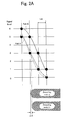
- FIG. 3A is a diagram showing a relationship between two paths representing ideal patterns of a reproduction signal which corresponds to a leading edge of a mark and an actual waveform, which is used in the method of detecting edge shift amounts according to an embodiment of the present invention.
- a path shown by a bold solid line is a correct answer, and a leading edge of a mark B ⁇ which corresponds to an actual input signal is delayed from the leading edge of the ideal mark B.
- FIG. 3B is a diagram showing a relationship between two paths representing ideal patterns of a reproduction signal which corresponds to a leading edge of a mark and an actual waveform, which is used in the method of detecting edge shift amounts according to an embodiment of the present invention.
- a path shown by a bold solid line is a correct answer, and a leading edge of a mark B+ which corresponds to an actual input signal comes earlier than the leading edge of the ideal mark B.
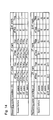
- FIG. 4 is a table showing values of parameters of recording pulse conditions generated at a first step of a method for optimizing the recording pulse conditions according to an embodiment of the present invention.
- FIG. 5 is a table showing values of parameters of recording pulse conditions generated at a fourth step of the method for optimizing the recording pulse conditions according to an embodiment of the present invention.
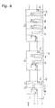
- FIG. 6 is a waveform diagram showing correspondence between parameters of recording pulse conditions used in the method for optimizing the recording pulse conditions according to an embodiment of the present invention and waveforms of the recording pulses.
- FIG. 7 is a waveform diagram showing correspondence between changes in values of parameters among the recording pulse conditions shown in FIG. 5 and changes in the waveforms of the recording pulses.
- FIG. 8 is a graph showing ideal eight patterns of a reproduction signal corresponding to an edge of a mark which is used in the method of detecting edge shift amounts according to an embodiment of the present invention.
- FIG. 9 is a table for specifying paths which corresponds to combinations of space lengths and mark lengths from the patterns shown in FIG. 8 .
- FIG. 10 is a plan view showing a structure of an optical information recording medium according to an embodiment of the present invention.
- FIG. 11 is a table showing edge shift amounts obtained at a fifth step of the method for optimizing the recording pulse conditions according to an embodiment of the present invention for each of the combinations between the mark lengths and the space lengths.
- FIG. 12 is a table showing values of parameters of recording pulse conditions compensated at a seventh step of the method for optimizing the recording pulse conditions according to an embodiment of the present invention.
- FIG. 13 is a flow diagram showing the method for optimizing the recording pulse conditions according to an embodiment of the present invention
- FIG. 14 is a diagram showing values of parameters of the recording pulse conditions generated at a ninth step of the method for optimizing the recording pulse conditions according to an embodiment of the present invention.
- FIG. 15 is a plan view which schematically showing 2T marks, 3T marks, and 5T marks formed on tracks of the optical disc with the recording pulses shown in FIG. 7 .
- an optical information recording medium In an optical information recording medium according to an embodiment of the present invention, laser light applied from outside forms marks having different physical properties to record data.
- a rewritable phase change optical disc (particularly, a rewritable blu-ray disc (BD-RE), which is simply referred to as an optical disc hereinafter) is used.
- an optical disc 101 As shown in FIG. 10 , an optical disc 101 is preferably separated into a data area 1001 , a recording condition calibration area 1002 , and a disc information pre-recorded area 1003 .
- the data area 1001 covers most of the optical disc 101 . User data is recorded on the data area 1001 .
- the recording condition calibration area 1002 is provided on an inner peripheral portion of the optical disc 101 and is adjacent to the data area 1001 . Onto the recording condition calibration area 1002 , trial recording for learning recording conditions is performed. Trial recording is performed when a recording and reproduction apparatus is turned on, when a temperature changes, and before data is recorded onto the data area 1001 . The recording and reproduction apparatus adjusts the recording conditions (particularly, recording power, recording pulse condition and the like) by the trial recording.
- the disc information pre-recorded area 1003 is provided in an innermost portion of the optical disc 101 and is adjacent to the recording condition calibration area 1002 .
- the disc information pre-recorded area 1003 Onto the disc information pre-recorded area 1003 , a recommended value for the recording power, a recommended value for the recording pulse condition (hereinafter, referred to as a recording pulse standard condition), recording linear speed, disc ID, and the like, which are preset for each optical disc 101 , are recorded.
- the disc information pre-recorded area 1003 is a read-only area.
- the information is preferably recorded semipermanently by using a formed portion on a substrate of the optical disc 101 such as meandering (wobbling) of tracks, pits and the like.
- a recording and reproduction apparatus includes a light irradiation unit 102 , a preamplifier unit 103 , an AGC unit 104 , a waveform equalization unit 105 , an A/D conversion unit 106 , a PLL unit 107 , a pattern detection unit 108 , an edge shift detection unit 109 , a recording pulse condition demodulation unit 114 , a recording pulse condition calculation unit 110 , a recording pattern generation unit 111 , a recording compensation unit 112 , and a laser drive unit 113 .
- components other than the laser drive unit 113 are integrated into one semiconductor integrated circuit 100 .
- the laser drive unit 113 may be further integrated to the semiconductor integrated circuit 100 .
- the light irradiation unit 102 is preferably an optical pickup and includes a laser diode and a photodetector.
- the laser diode irradiates laser light onto the optical disc 101 mentioned above.
- the photodetector detects laser light reflected off the optical disc 101 and converts it into an electrical signal to output as an analog reproduction signal.
- the analog reproduction signal is processed by the preamplifier unit 103 , the AGC (automatic gain control) unit 104 , the waveform equalization unit 105 and the A/D conversion unit 106 in turn, and is converted into a digital reproduction signal.
- the PLL unit 107 extracts reproduction clock from the digital reproduction signal.
- the A/D conversion unit 106 samples the analog reproduction signal in accordance with the reproduction clock.
- the pattern detection unit 108 preferably includes a maximum likelihood decoding unit (preferably a viterbi decoding unit).
- the pattern detection unit 108 first shapes the digital reproduction signal such that it conforms to frequency characteristics of the maximum likelihood decoding unit (preferably PR(1, 2, 2, 1) characteristics).
- the maximum likelihood decoding unit converts the digital reproduction signal by the maximum likelihood decoding method (preferably viterbi decoding method) into a digitized signal (preferably a non return to zero inverted (NRZI) signal). Then, the pattern detection unit 108 selects a pattern having a shape close to a portion of the digital reproduction signal which corresponds to an edge of a mark based on the digitized signal from a predetermined group of patterns (see FIG. 8 ).
- the edge shift detection unit 109 compares the pattern selected by the pattern detection unit 108 with the shape of the above-mentioned portion of the digital reproduction signal, and measures an amount of edge shift of the mark (shift of an actual edge position of the mark from an ideal edge position of the mark).
- the recording pulse condition demodulation unit 114 extracts a recording pulse standard condition recorded on the optical disc 101 from the above digitized signal.
- the recording pulse condition calculation unit 110 modifies parameters included in the recording pulse standard condition.
- the recording pulse condition calculation unit 110 particularly compensates the above parameters based on the measured edge shift amount.
- the recording pattern generation unit 111 outputs a predetermined recording signal preferably as an NRZI signal when data is recorded to the optical disc 101 .
- the recording compensation unit 112 sets the recording pulse condition in accordance with the result of calculation by the recording pulse condition calculation unit 110 .
- the recording compensation unit 112 converts the above NRZI signal into a recording pulse in accordance with the recording pulse condition.
- the laser drive unit 113 drives a laser diode in the light irradiation unit 102 .
- the laser drive unit 113 controls the power of the laser light in accordance with the above recording pulse particularly for recording data to the optical disc 101 and records data on the optical disc 101 .
- the optical disc 101 has a track pitch of 0.32 ⁇ m.
- a thickness of a cover layer which covers a surface on which the laser light impinges is between 75 and 100 ⁇ m.
- the recording and reproduction apparatus preferably optimizes the recording pulse condition for recording data onto the optical disc 101 in accordance with a flow diagram shown in FIG. 13 .
- the recording and reproduction apparatus first accesses the disc information pre-recorded area 1003 of the optical disc 101 to read out the initial value information.
- the recording pulse condition demodulation unit 114 extracts the recording pulse condition from the read out initial value information.
- the extracted recording pulse standard condition is stored into different memory areas for each of the parameters.
- the recording pulse conditions preferably include parameters shown in FIG. 4 . These parameters are classified into parameters related to a 2T mark, parameters related to a 3T mark, and parameters related to a mark having a length of 4T or longer.
- the parameters DTtop, Ttop, Tlp, and dTe shown in FIG. 4 define waveforms of recording pulses (see FIG. 6 ).
- the recording pulses preferably include a first pulse PT, a middle pulse PM, a last pulse PL, and a cooling pulse PC.
- the first pulse PT and the cooling pulse PC are used for recording all kinds of marks.
- the last pulse PL is preferably used for recording a mark having a length of 3T or longer.
- the middle pulse PM is preferably used for recording a mark having a length of 4T or longer, and the number thereof increases as the mark length increases.
- the first parameter dTtop represents a leading edge of the first pulse PT with respect to a predetermined reference position of the NRZI signal.
- the second parameter Ttop represents a width of the first pulse PT.
- the third parameter Tlp represents a width of the last pulse PL.
- the fourth parameter Tmp represents a width of the middle pulse PM.
- the fifth parameter dTe represents a trailing edge of the cooling pulse PC with respect to a predetermined reference position of the NRZI signal.
- the first parameter dTtop and the fifth parameter dTe have polarities.
- a leftward direction (a direction from the trailing edge of a mark toward the leading edge) is a positive direction.
- Values a through k of parameters shown in FIG. 4 are represented preferably in units of reference time interval Tw determined by recording clocks.
- the values a through k of parameters shown in FIG. 4 can be represented by integral multiples of the unit Tw/16.
- that value H of the first parameter dTtop related to marks having a length of 4T or longer represents that “the leading edge of the first pulse PT is at a position of h ⁇ Tw/16 [nsec] from the predetermined reference position of the NRZI signal”.
- the recording and reproducing apparatus uses values recorded on the optical disc 101 as they are.
- the values of the recording pulse standard conditions recorded on the optical disc 101 are represented in units of nanoseconds
- the recording and reproducing apparatus converts the values to integral values closest to the unit Tw/16.
- the recording and reproducing apparatus may divide into units smaller than those of the values recorded on the optical disc 101 . This improves precision of compensation.
- the edge positions of the marks can be adjusted with a high precision. Therefore, quality of a signal read out from a written mark improves.
- the recording and reproducing apparatus doubles the values read out from the optical disc 101 and stores into the memory. In this way, the unit can be set to half the above unit, Tw/32.
- the recording pulse condition calculation unit 110 sets values h, i, j, and k of the four parameters dTtop, Ttop, Tlp and dTe related to marks having a length of 4T or longer among the parameters included in the recording pulse standard condition A read out from the optical disc 101 as reference values.
- the recording pulse condition calculation unit 110 further modifies the reference values as follows to set two different recording pulse conditions B and C (See FIG. 4 ).
- the recording pulse condition calculation unit 110 first increases the reference values h, i and j of three parameters dTtop, Ttop, and Tlp by one unit, and reduces the reference value k of the fourth parameter dTe by one unit to store it as the recording pulse condition B into the memory.
- the recording pulse condition calculation unit 110 first reduces the reference values h, i and j of three parameters dTtop, Ttop, and Tlp by one unit, and increases the reference value k of the fourth parameter dTe by one unit to store it as another recording pulse condition C into the memory.
- a width of the first pulse PT which is included in a portion of a recording pulse which corresponds to a 5T mark, is expanded compared to that of the recording pulse standard condition A. Also, a rising position comes earlier. Thus, a leading edge of the 5T mark comes earlier.
- a width of the last pulse PL expands and a phase of the cooling pulse PC is delayed, a trailing edge of the 5T marks comes later. Accordingly, with the recording pulse condition B, a mark having a length of 4T or longer becomes longer compared to that with the recording pulse standard condition A.
- the recording pulse condition C a width of the first pulse PT, which is included in a portion of the recording pulse which corresponds to a 5T mark, is smaller compared to that with the recording pulse standard condition A. Further, the rising position is delayed. Thus, a leading edge of the 5T mark comes late. Further, since the width of the last pulse PL is reduced and the phase of the cooling pulse PC advances, a trailing edge of the 5T mark comes earlier. Accordingly, with the recording pulse condition C, marks having a length of 4T or longer becomes shorter than that with the recording pulse standard condition A.
- the recording and reproducing apparatus first moves an optical spot to be applied onto the optical disc 101 from the light irradiation unit 102 to a track in the recording condition calibration area 1002 to perform focusing and tracking.
- the recording and reproducing apparatus performs trial recording of a recording signal having one predetermined pattern onto the recording condition calibration area 1002 of the optical disc 101 (see FIG. 10 ) using each of three recording pulse conditions A, B and C.
- marks and spaces included in the employed pattern are all longer than the spot size of the laser of the light irradiation unit 102 by a sufficient amount.
- the recording pattern generation unit 111 generates a single pattern formed of repetition of 5T marks and 5T spaces (hereinafter, referred to as 5T single signal).
- the recording compensation unit 112 generates recording pulses from the recording 5T single signal and the recording pulse conditions A, B, and C.
- the laser drive unit 113 drives the laser diode in the light irradiation unit 102 in accordance with the recording pulses and sequentially writes the 5T single signal onto tracks of the optical disc 101 in units of sectors. In this way, patterns of the 5T single signal are sequentially recorded on the recording condition calibration area 1002 of the optical disc 101 for three sets of recording pulse conditions A, B, and C, respectively.
- the recording and reproducing apparatus sequentially reproduces the 5T single signal written by using the recording pulse conditions A, B, and C from the recording condition calibration area 1002 of the optical disc 101 to measure the edge shift amounts or asymmetry of the reproduction signals.
- the reproduction signal output from the light irradiation unit 102 is processed at the preamplifier unit 103 , the AGC unit 104 , the waveform equalization unit 105 , and the A/D conversion unit 106 in turn, and is converted into a digitized signal by the maximum likelihood decoding unit in the pattern detection unit 108 .
- the pattern detection unit 108 measures the edge shift amount of the reproduction signal based on the digitized signal. In this example, it is assumed that the maximum likelihood decoding unit conforms to the PR (1, 2, 2, 1) method.
- the pattern detection unit 108 selects a pattern having a shape close to the shape of the portion of a digital reproduction signal input into the maximum likelihood decoding unit (hereinafter, referred to as an input signal) which corresponds to an edge of a mark from a predetermined group of patterns (see FIG. 8 ).
- the pattern group preferably includes eight patterns (Pattern- 1 through Pattern- 8 ).
- the horizontal axis indicates time (one division of the scale represents one cycle of channel clock; the vertical axis indicates a level of the input signal shaped so as to conform to the PR (1, 2, 2, 1) characteristics by the pattern detection unit 108 ).
- the PR (1, 2, 2, 1) characteristics may have six levels, 0 through 6.
- two types of paths, PXA and PXB correspond to two values of the central bit (for example, path P 2 A of Pattern- 2 represents a bit sequence “1, 1, 1, 0, 0, 0, 0”.
- FIG. 8 four patterns shown in the upper part (Pattern- 1 , Pattern- 2 , Pattern- 3 , and Pattern- 4 ) correspond to leading edges of the marks; four patterns shown in the lower part (Pattern- 5 , Pattern- 6 , Pattern- 7 , and Pattern- 8 ) correspond to trailing edges of the marks. As shown in FIG.
- each of paths having such patterns corresponds to one of the combinations of the mark lengths and the space lengths.
- the single pattern recorded on the optical disc 101 at the second step is a repetition of 5T marks and 5T spaces.
- the shape of the portion of the input signal corresponds to the leading edge of the 5T mark has Pattern- 2 (see FIG. 9 ).
- the pattern detection unit 108 selects Pattern- 2 for the leading edge of the 5T mark.
- the shape of the portion of the input signal corresponds to the trailing edge of the 5T mark has Pattern- 7 (see FIG. 9 ).
- the pattern detection unit 108 selects Pattern- 7 for the trailing edge of the 5T mark.
- the edge shift detection unit 109 compares Pattern- 2 selected by the pattern detection unit 108 with the shape of the portion of the input signal which corresponds to the leading edge of the 5T mark and measures the edge shift amount at the leading edge of the 5T mark as follows (see FIGS. 2 and 3 ).
- the portion of the input signal which corresponds to the leading edge of the 5T mark ideally shows one of two paths A and B included in Pattern- 2 (shown by broken lines and bold solid lines in FIGS. 2 and 3 ). Accordingly, the corresponding portions of the actual input signal should have the shapes similar to one of two paths A and B.
- fine solid lines show actual input signals.
- FIGS. 2A and 2B show an example where path A is a correct answer. The shape of the actual input signal is similar to that of path A.
- FIGS. 3A and 3B show an example where path B is a correct answer. The shape of the actual input signal is similar to that of path B.
- FIGS. 1A and 2B show an example where path A is a correct answer.
- path B is a correct answer.
- the shape of the actual input signal is similar to that of path B.
- sample values sampled from the actual input signals at channel clock cycle are indicated by triangles.
- the edge shift detection unit 109 calculates a square sum of differences between the expected values of the samples included in path A (indicated by solid circles in FIG. 2 ) and actual sample values (triangles) and determine as a distance Pa between the path A and the actual input signal. Similarly, the edge shift detection unit 109 determines a distance Pb between path B and the actual input signal. The edge shift detection unit 109 further compares the two distances Pa and Pb. When the former distance Pa is small, path A is regarded as the correct answer; when the latter distance Pb is smaller, path B is regarded as the correct answer.
- the group of samples of the actual input signal can be divided into a sample group having path A as the correct answer and a sample group having path B as the correct answer.
- the edge shift detection unit 109 subtracts a positive constant, Pstd, from a difference between two paths Pa and Pb,
- the positive constant Pstd represents a difference between two distances Pa and Pb when the input signal matches one of two paths A and B.
- Pstd.
- the edge shift detection unit 109 determines the edge shift amount from the obtained value
- the magnitude of the edge shift amount is defined by the magnitude of the obtained value
- the sign of the edge shift amount is defined so as to conform to a direction of the shift in the edge position.
- the sign of the edge shift amount is defined to be positive when the shift in the edge position is in a direction toward left (a direction from the trailing edge toward the leading edge of the mark).
- the sample group having path A as the correct answer and that having path B as the correct answer have opposite correspondences between the signs of the obtained value
- the sign of the edge shift amount is defined as follows based on the sign of the obtained value
- the leading edge of the mark A ⁇ corresponding to the actual input signal is delayed compared to the leading edge of the ideal mark A.
- the leading edge of the actual mark A ⁇ is shifted from the leading edge of the ideal mark A in the negative direction.
- the waveform of the actual input signal is within the region between two paths A and B.
- the leading edge of the mark A+ corresponding to the actual input signal is earlier compared to the leading edge of the ideal mark A.
- the leading edge of the actual mark A+ is shifted from the leading edge of the ideal mark A in the positive direction.
- the waveform of the actual input signal is outside the region between two paths A and B.
- the leading edge of the mark B ⁇ corresponding to the actual input signal is delayed compared to the leading edge of the ideal mark B.
- the leading edge of the actual mark B ⁇ is shifted from the leading edge of the ideal mark B in the negative direction.
- the waveform of the actual input signal is outside the region between two paths A and B.
- the leading edge of the mark B+ corresponding to the actual input signal is earlier compared to the leading edge of the ideal mark B.
- the leading edge of the actual mark B+ is shifted from the leading edge of the ideal mark B in the positive direction.
- the waveform of the actual input signal is within the region between two paths A and B.
- the edge shift detection unit 109 compares the paths A and B of Pattern- 7 selected by the pattern detection unit 108 with a shape or a portion of the input signal which corresponds to the trailing edge of the 5T mark. As described above, the edge shift amounts 5M5S A and 5M5S B at the trailing edge of the 5T mark are calculated for each of the sample groups having the paths A and B as correct answers. As below the edge shift detection unit 109 further calculates averages of the edge shift amounts at the leading edge and the trailing edge of the 5T mark among two sample groups. The average values are determined as the edge shift values 5S5M and 5M5S at the leading edge the trailing edge of the 5T mark.
- the shift in length, L 5T represents an amount of shift from a normal length of the 5T mark, 5T. If the length shift L 5T is 0, the 5T mark has the same length as the 5T space. If the length shift L 5T has a positive value, the 5T mark is longer than the 5T space. If the length shift L 5T has a negative value, the 5T mark is shorter than the 5T space. In other words, if the length shift L 5T is large, asymmetry is biased toward the mark; if the length shift L 5T is small, asymmetry is biased toward the space.
- the length shift L 5T is calculated for each of the single patterns recorded on the optical disc 101 by using the recording pulse conditions A, B and C.
- the edge shift detection unit 109 selects the length shift L 5T having the value closest to a predetermined target value from the obtained three values of length shift L 5T .
- the target value is preferably target asymmetry information pre-recorded in the disc information pre-recorded area 1003 (see FIG. 10 ) of the optical disc 101 . If the target asymmetry information is not recorded in the disc information pre-recorded area 1003 , an initial value pre-stored in the recording and reproduction apparatus (preferably, “0” which indicates that there is no asymmetric state) is set as the above-mentioned target value.
- a conversion coefficient for corresponding the value indicated by the information to the length shift L 5T may be previously set to the recording and reproducing apparatus.
- the value converted by using the conversion coefficient can be set as the above-mentioned target value.
- the edge shift detection unit 109 further selects the recording pulse condition which is used for recording the single pattern corresponding to the selected length shift L 5T as an optimal condition. For example, if the length shift L 5T obtained from the single pattern recorded using the pulse condition A is closest to 0, the recording pulse condition A is selected as the optimal condition. The same is also true of recording pulse conditions B and C.
- the recording pulse condition calculation unit 110 sets the values of the parameters included in the recording pulse condition C instead of those of recording pulse standard condition A as reference values, and generates the remaining two recording pulse conditions as in the first step. After repetition of such a process, when the difference between the actually measured length shift L 5T and the target value becomes below the threshold value, the recording pulse condition corresponding to the length shift L 5T is selected as the optimal condition.
- the recording pulse condition calculation unit 110 employs the values of the parameters included in the recording pulse standard condition A as reference values and newly sets two sets of recording conditions B and C by changing the reference values by ⁇ 1 unit (see FIG. 4 ). Besides, when the difference between the recording pulse standard condition previously recorded on the optical disc 101 and the recording and reproducing property of the recording and reproducing apparatus is large, the recording pulse condition calculation unit 110 may modify the reference value not only by ⁇ 1 unit but also by ⁇ 2 units and may set five sets of recording pulse conditions including the recording pulse standard condition A. More preferably, the recording and reproducing apparatus may use each of the five recording pulse conditions at the second step to perform trial writing of the single pattern onto the recording learning area 1002 of the optical disc 101 .
- the number of samples of the length shift L 5T increases at the third step.
- a probability that the optimal recording pulse condition is determined by the trial writing of only once.
- the time required for learning recording pulse condition can be further shorted in terms of long marks.
- the same recording pulse condition is set for marks having the length of 4T or longer (see FIG. 4 ). Therefore, the above-mentioned single pattern is not limited to a 5T single signal. Any single pattern formed of a mark having a length of 4T or longer and a space having a length of 4T or longer may be used. If a method for modulating the recording signal is 17PP modulation, the central value of the mark length distribution is about 5T. By using the 5T single mark for optimizing the recording pulse conditions, an average value of edge shifts of long marks having the length of 4T or longer can be readily aligned. This is why it is preferable to use the 5T single signal in view of further enhancing the recording quality.
- a single pattern formed of a combination of an 8T mark and an 8T space (hereinafter, simply referred to as 8T single signal) may be used for trial recording.
- the reproduction waveform of the 5T single signal is similar to a sine waveform.
- basic waves, second harmonics, third harmonics, and fourth harmonics are signal bandwidth.
- the reproduction waveform of the 8T single signal has a rectangular shape.
- the reproduction signal can be adjusted by detecting the waveform of a rectangular shape. For example, when a trailing edge of a mark is over-heated while recording, a portion near the trailing edge of the mark further expands from an appropriate shape. Such expansion can be readily detected from the reproduction waveform of the 8T single signal.
- the information for compensating the parameters of the recording pulse conditions which are related to the trailing edge of the mark can be readily obtained.
- the recording and reproducing apparatus uses not only the parameters related to long marks which are optimized at the third step but also parameters related to 2T marks and 3T marks which are included in the recording pulse standard condition A and generates three new sets of recording pulse conditions D, E, and F (see FIG. 5 ). Furthermore, each of the new recording pulse conditions D, E, and F are used to perform trial writing of a recording signal having a specific pattern onto the recording condition calibration area 1002 of the optical disc 101 (see FIG. 10 ).
- FIG. 5 shows recording pulse conditions D, E, and F.
- the recording pulse condition D values of the parameters related to 2T marks and 3T marks are equal to values a through g in the recording pulse standard condition A.
- the recording pulse condition calculation unit 110 first sets values a through g of seven parameters related to 2T marks and 3T marks included in the recording pulse condition D as reference values.
- the recording pulse condition calculation unit 110 increases the reference values a, b, d, and e of the parameters dTtop and Ttop by one unit, and stores them with other reference values c, f, and g as the recording pulse condition E.
- the recording pulse condition calculation unit 110 further reduces the reference values a and c of two parameters related to 2T marks by one unit and increases the reference values d and g of two parameters related to 3T marks by one unit.
- the recording pulse condition calculation unit 110 also reduces the reference value f of the parameter Tp related to 3T marks by one unit and stores them with remaining two reference values b and e as the recording pulse condition F.
- the recording pulse condition E widths of first pulses PT included in recording pulses corresponding to a 2T mark 2Tm and a 3T mark 3Tm are expanded compared to those in the recording pulse condition D. And the rising positions come earlier (they are shifted toward the left side in FIG. 7 ). Therefore, in the recording pulse condition E, the leading edges of the 2T mark 2Tm and the 3T mark 3Tm come earlier than in the recording pulse condition D and the marks extend more (see FIG. 15 ).
- the recording pulse condition E is set mainly for adjusting mark lengths.
- a central phase P 2T (E) of the 2T mark 2Tm is changed in the same direction as a central phase P 3T (E) of the 3T mark 3Tm.
- the first pulse PT and a cooling pulse PC included in a portion of the recording pulse which corresponds to the 2T mark 2Tm have phases delayed compared to those in the recording pulse condition D (they are shifted toward the right side in FIG. 7 ).
- a phase of the first pulse PT advances, a width of the last pulse PL is reduced, and a phase of the cooling pulse PC advances (they are shifted toward the left side in FIG. 7 ).
- the phase of the 2T mark 2Tm is delayed and the phase of the 3T mark 3Tm advances compared to those in the recording pulse condition D (see FIG. 15 ).
- the recording pulse condition F is set mainly for adjusting phases of marks. Particularly, the central phase P 2T (F) of the 2T mark 2Tm is changed in the opposite direction to the central phase P 3T (F) of the 3T mark 3Tm.
- the phases P 2T (E) and P 3T (E) of the 2T mark 2Tm and the 3T mark 3Tm recorded on the optical disc 101 using the recording pulse condition E change in the same direction as the phases P 2T (D) and P 3T (D) of the marks recorded with the recording pulse condition D (see FIG. 15 ). Therefore, generally, there is a phase difference in reproduction clocks obtained by the PLL unit 107 (see FIG. 1 ) between signals reproduced from the marks recorded respectively using the recording pulse conditions D and E. In such a case a shift in the phase of the 2T mark 2Tm is included as an error in measuring edge shift amount of the 3T mark.
- the shift in the phase of 3T mark 3Tm is included as an error of measuring the edge shift amount of the 2T mark.
- the edge shift amounts cannot be measured correctly.
- the phase P 2T (F) of the 2T mark 2Tm changes in the opposite direction as the phase P 3T (F) of the 3T mark 3Tm.
- the influence of the reproduction clock on the phase is cancelled. Therefore, the phase difference of the general clock is generally small in signals reproduced from the marks recorded using two recording pulse conditions D and F. As a result, the error in measuring the edge shift amount can be further reduced.
- the leading edges may be changed in the opposite directions between the 2T mark and the 3T mark as in the recording pulse condition F.
- the phases P 2T (E) and P 3T (E) of the 2T mark 2Tm and the 3T mark 3Tm may be changed in the opposite direction as the phases P 2T (D) and P 3T (D) of the marks recorded with the recording pulse condition D. In this way, the error in measuring the edge shift amount may be reduced as in the recording pulse condition F.
- a method for setting the recording pulse condition E may be different from the method mentioned above (see FIGS. 5 and 7 ).
- the position of the first pulse dTtop may be changed (by one unit, for example) with the width Ttop of the first pulse being fixed.
- the position of the first pulse Ttop may be changed (by one unit, for example) with the rising position dTtop of the first pulse being fixed.
- the width of the last pulse Tlp may be changed by one unit, for example, or the rising position of the cooling pulse dTe may be changed by one unit, for example.
- the rear end of the first pulse does not overlap the front end of the following pulse (a middle pulse or the last pulse) since the falling position of the first pulse is fixed.
- the space between the first pulse and the following pulse does not become too small. Therefore, a correct waveform of the recording pulse can be obtained.
- a method for setting the recording pulse condition F may be different from the method mentioned above (see FIGS. 5 and 7 ).
- the phase of the last pulse may be changed with the width Tlp of the last pulse being fixed.
- an amount of change in the length of the 3T mark, L 3T (F) may be suppressed (see FIG. 15 ).
- the interference between the mark length and the phase is reduced, and the amount of change in the phase P 3T (F) (see FIG. 15 ) can be detected more precisely.
- the frequencies of the appearances of code lengths from 2T to 8T are almost equal, and also digital sum value (DSV) control is performed.
- DSV digital sum value
- the conventional recording patterns are modulated by the 17PP modulation method in the same way as the user data.
- the appearance probability of 2T marks is about 38%, while the appearance probability of 3T marks is about 25% and the appearance probability of 4T marks is about 16%.
- the appearance probability of long marks having a length of 5T or longer is further lower.
- the appearance frequency of the code length decreases as the code lengths increases.
- the phase of the reproduction clock obtained by the PLL unit 107 from the recording pattern written onto the optical disc 101 is determined based mostly on the phase of the short marks of a high appearance frequency (particularly, 2T marks having the appearance possibility of 1 ⁇ 3 or higher).
- the edge positions of short marks largely vary among the recording pulse conditions D, E and F.
- the phase of the reproduction clock obtained from the conventional recording pattern largely varies.
- the edge shift amount and/or phase measured from the long marks having a length of 4T or longer (which has already small edge shift amount by the third step) include a significant error.
- the recording pattern used at the fourth step has appearance frequency substantially equal for all the code lengths. This means that the appearance probability for the 2T marks and the 3T marks are respectively 1/7 while the frequency that any of the marks having a length of 4T or longer is 5/7. Thus, most of the marks in the recording pattern used at the fourth step are the long marks having a length of 4T or longer.
- the phase of the reproduction clock obtained by the PLL unit 107 from the recording pattern written onto the optical disc 101 is determined based mostly on the phase of the long marks. As a result, the phase of the reproduction clock is stable irrespective of changes in the edge position of the 2T marks and the 3T marks.
- the edge shift amount of the 2T marks and 3T marks can be measured with a high accuracy at the fifth step.
- the recording and reproducing apparatus uses the recording pulse conditions D, E and F, respectively, to perform trial writing of the recording pattern mentioned above onto the recording condition calibration area 1002 of the optical disc 101 (see FIG. 10 ) as in the second step.
- the parameters of the recording pulse condition related to the 4T mark may be changed and trial recording may be performed similarly to the parameters related to the 3T marks.
- the edge shift amount is measured not only for short marks but also for the 4T marks, and the parameters related to the 4T marks are compensated based on the measured result.
- amounts of changes in the parameters dTtop, Ttop, Tlp, and dTe may not only be equal to the minimum unit which can be set by the recording and reproducing apparatus, but also be twice as large as or larger than the unit.
- the edge shift amount when the parameter is changed by one unit is converted from the edge shift amount measured at the fifth step. In this way, the edge shift amount when the parameter is changed by one unit can be measured accurately even with an optical disc which experiences only a small amount of edge shift when the recording pulse condition is changed.
- the recording and reproducing apparatus reproduces the recording patterns sequentially from tracks on which the above mentioned recording pattern is recorded with the recording pulse conditions D, E and F and measures the edge shift amounts of the reproduction signals.
- the reproduction signal output from the light irradiation unit 102 is processed at the preamplifier unit 103 , the AGC unit 104 , the waveform equalization unit 105 , and the A/D conversion unit 106 in turn, and is converted into a digitized signal by the maximum likelihood decoding unit in the pattern detection unit 108 .
- the pattern detection unit 108 measures the edge shift amount of the reproduction signal based on the digitized signal. In this example, it is assumed that the maximum likelihood decoding unit conforms to the PR (1, 2, 2, 1) method.
- the fundamental principle of measurement of the edge shift amount is as described in the description of the third step.
- a difference in the fifth step from the third step is the pattern selected by the pattern detection unit 108 (see FIGS. 8 and 9 ).
- the pattern detection unit 108 uses Pattern- 3 and Pattern- 4 for detecting the leading edge of a 2T mark, Pattern- 6 and Pattern- 8 for detecting a trailing edge of a 2T mark, Pattern- 1 through Pattern- 4 for detecting a leading edge of a 3T mark, and Pattern- 5 through Pattern- 8 for detecting a trailing edge of a 3T mark. More specifically, for detecting a leading edge of a 3T mark following a 2T space, path P 3 A of Pattern- 3 is selected.
- path P 1 B of Pattern- 1 and path P 4 A of Pattern- 4 are selected.
- the parameters of the recording pulse condition are optimized such that portions of the reproduction signal corresponding to a leading end and a trailing end of the mark become closer to paths shown in FIG. 9 for any of combinations between the mark lengths and the space lengths. Such parameters are optimal for data reproduction by the maximum likelihood decoding.
- a path is not set for any of a pattern including a 2T mark immediately after a 2T space and a pattern including a 2T space immediately after a 2T mark.
- These patterns cannot be detected with the eight patterns (Pattern- 1 through Pattern- 8 ) shown in FIG. 8 .
- a method different from the method below may be used for measuring the edge shift amount for those patterns.
- those patterns tend to be detected erroneously as a pattern having a code length of 1T which is not used for 17PP modulation.
- errors caused by such patterns can be readily identified.
- the recording pulse condition does not have to be optimized for each of the optical discs 101 in terms of those patterns, and a suitable initial value may be used uniformly.
- the edge shift detection unit 109 measures the edge shift amount of the 2T marks and 3T marks. For example, regarding the leading edge of the 3T mark, the edge shift detection unit 109 measures the edge shift amount as described below for each of four candidates P 3 A, P 1 B, P 4 A, and P 2 B for correct paths selected by the pattern detection unit 108 . When there is a 4T space immediately before a 3T mark, the pattern detection unit 108 selects path P 2 B of Pattern- 2 and path P 4 A of the Pattern- 4 (see FIGS. 8 and 9 ).
- the edge shift detection unit 109 compares waveforms of the corresponding portions of the input signal to the maximum likelihood decoding unit with the paths P 2 B and P 4 A and calculates the edge shift amounts 4S3M B and 4S3M A for the sample groups having the paths P 2 B and P 4 A as correct answers based on the distances between them.
- waveforms of the corresponding portions of the input signal are compared with the paths P 2 B and P 4 A and the edge shift amounts 5S3M B and 5S3M A are calculated for the sample groups having the paths P 2 B and P 4 A as correct answers based on the distances between them.
- the average value between them is determined as the edge shift amount 5S3M where there is a space having a length of 5T or longer is immediately before a 3T mark.
- the patterns shown in FIGS. 8 and 9 are compared with the waveforms of the corresponding portions of the input signal for each length of the space immediately before a 3T mark to measure the edge shift amount.
- the edge shift amount is shown in FIG.
- variables shown in FIG. 11 represent average values of the edge shift amounts among sample groups having the paths PXA and PYB as correct answers.
- the edge shift detection unit 109 further calculates the average edge shift amount for each of the mark lengths regardless of the length of the spaces on the front and back side from the edge shift amounts obtained from the combinations of the mark lengths and space lengths.
- the edge shift amounts for different lengths of the space immediately before are averaged with being weighted in accordance with the number of the samples mentioned above to obtain the average edge shift amounts of the leading edges of the marks.
- the edge shift detection unit 109 obtains average edge shift amounts xS2M and xS3M of the leading edges and average edge shift amounts 2MxS and 3MxS of trailing edges respectively for 2T marks and 3T marks through calculation.
- phase shift P iT When phase shift P iT is 0, the actual phase of an iT mark matches the phase.
- phase shift P iT has a positive value, the actual phase of an iT mark advances from the normal phase; when phase shift **L iT has a negative value, the actual phase of an iT mark is delayed from the normal phase.
- the recording pulse condition calculation unit 110 compares the length shifts L 2T and L 3T and phase shifts P 2T and P 3T from the 2T marks and the 3T marks with the predetermined threshold values for a signal generated by reproducing the recording pattern recorded using the recording pulse condition D. If the length shifts L 2T and L 3T and phase shifts P 2T and P 3T all do not exceed the threshold values, the recording pulse condition calculation unit 110 determines the recording pulse condition D as the optimal recording pulse condition and finishes the optimizing process for recording pulse conditions. Alternatively, when the compensation values m and n to be obtained at the seventh step which will be described below both become zero, the recording pulse condition calculation unit 110 finishes the optimizing process for the recording pulse condition.
- the recording pulse condition calculation unit 110 continues the process of the seventh step and the following steps to perform compensations of the recording pulse conditions.
- the square sum thereof, jitters of the reproduction signal, or a combination of any other indicators representing the quality of the reproduction signal may be used.
- the recording pulse condition calculation unit 110 calculates a compensated value of the recording pulse condition based on the length shifts L 2T and L 3T and phase shifts P 2T and P 3T of the 2T marks and the 3T marks obtained for each of the recording pulse conditions D, E, and F. For the calculation, the following parameters are used:
- Compensation amounts of mark lengths m 2T and m 3T and compensation amounts of mark phases n 2T and n 3T (preferably, m 2T , m 3T , n 2T and n 3T are all represented by integral multiples of units of parameters of the recording pulse conditions).
- the recording pulse condition calculation unit 110 calculates the differences in length shifts, L12 2T , L12 3T , L13 2T and L13 3T , and differences in phase shifts, P12 2T , P12 3T , P13 2T and P13 3T , as follows.
- the shift compensation equations (1) through (4) have the meaning as described below.
- the recording pulse condition E has values of parameters dTtop and Ttop different from those of the recording pulse condition D by ⁇ 1 unit (see FIGS. 5 and 7 ). Therefore, the length shift difference L12x and the phase shift difference P12x between the recording pulse conditions D and E are generated due to changes in the parameters dTtop and Ttop by ⁇ 1 unit.
- a length shift change and a phase shift change accompanied with changes in the parameters dTtop and Ttop are both proportional to the changes of the parameters dTtop and Ttop (linear approximation).
- the recording pulse condition F has values of parameters dTtop and dTe related to 2T marks different from those of the recording pulse condition D by ⁇ 1 unit, values of parameters dTtop and dTe related to 3T marks different from those or the recording pulse condition D by +1 unit, and value of parameters Tlp related to 3T marks different from that of the recording pulse condition D by ⁇ 1 unit (see FIGS. 5 and 7 ).
- the length shift difference L13x and the phase shift difference P13x between the recording pulse conditions D and F are generated due to changes in the parameters dTtop, Tlp and dTe by ⁇ 1 unit.
- the recording pulse condition E is set mainly for adjusting mark lengths; the recording pulse condition F is set mainly for adjusting mark lengths.
- the recording pulse condition E is set mainly for adjusting mark lengths; the recording pulse condition F is set mainly for adjusting mark lengths.
- a signal when a pattern recorded with the recording pulse condition E is reproduced not only the mark length shift Lx but also phase shift Px of the mark is changed.
- a signal when a pattern recorded with the recording pulse condition F is reproduced not only mark phase shift Px, but also mark length shift Lx is changed. Changes in the mark lengths and changes in mark phases accompanied with changes in the recording pulse condition are dependent on each other rather than being independent.
- the compensation amounts mx and nx obtained from equations (5) through (8) are further rounded off to whole numbers preferably from first decimal places.
- the obtained compensation amounts mx and nx are used and the recording pulse condition calculation unit 110 compensates the recording pulse condition as follows (see FIG. 12 ).
- the recording pulse condition calculation unit 110 first increases the reference values a and b of the parameters dTtop and Ttop related to 2T marks by the compensation amount m 2T of mark lengths.
- the recording pulse condition calculation unit 110 replaces the recording pulse condition D with the recording pulse condition G obtained by the above compensation as a initial condition. Thus, if it is determined that the process from the fourth step has been repeated at the eighth step described below, the values of the parameters in the recording pulse condition G are set as the reference values instead of the recording pulse condition D at the fourth stop in next turn.
- the target value for the length shifts and the phase shift is uniformly set to zero. In this way, the recording pulse condition is optimized such that a rate of occurrence of errors in the maximum likelihood decoding process is minimized.
- the target value may be set as a value different from 0, and a different value may be set for the 2T marks and the 3T marks.
- the compensation amounts mx and nx are preferably rounded off to whole numbers from first decimal places.
- the recording and reproducing apparatus preferably pre-stores the target values Ltx and Ptx for each of the types of optical discs.
- edge shift amounts are measured for each of combinations between the mark length and the length of the forward and backward spaces.
- the average edge shift amount for each of the mark lengths is calculated from the measured results, and the recording pulse condition is adjusted based on the average edge shift amount.
- the average edge shift amount is obtained by averaging out variances in the edge shift amounts due to the lengths of the spaces on the front and back of the mark.
- thermal interferences between the marks and the spaces may vary significantly in accordance with the length of the spaces on the front and back of the mark.
- the recording pulse condition has to be altered to conform not only to the mark lengths but also to the length of the spaces on the front and back sides.
- the number of combinations of the parameters which have to be included in the recording condition significantly increases along with the number of combinations between the mark lengths and the spaces lengths.
- the number of the parameters which have to be adjusted by trial recording is large, a time period required for learning is long. Furthermore, a large number of tracks in the recording condition calibration area 1003 are consumed.
- an optical disc which can record data only once such as a write-once read-many optical disc
- the number of times of learning is limited due to limitation on the track number of the recording condition calibration area.
- the eighth step whether further compensation in view of the length of the spaces in front and back of the mark is necessary or not is determined based on the type of the optical disc 101 and the result of the first through seventh steps.
- the ninth step and the following steps are skipped and the process is repeated from the fourth step.
- recording pulse conditions G, H, and I shown in FIG. 12 are used instead of the recording pulse conditions D, E, and F shown in FIG. 5 . Therefore, for compensating the recording pulse condition, only average edge shift amounts for each mark lengths are used. Since parameters to be compensated are limited, a time period required for adjusting the recording pulse conditions can be further reduced. Also, quality of the mark can be further improved.
- the process proceeds to the ninth step where further adjustment on the recording pulse conditions in accordance with the length of the spaces in front and back of the mark.
- ⁇ xS2M 2 [(3 S 2 M ⁇ xS 2 M ) 2 +(4 S 2 M ⁇ xS 2 M ) 2 +(5 S 2 M ⁇ xS 2 M ) 2 ]/3;
- a deviation ⁇ iMxS represents a magnitude of a variation in trailing edges in accordance with space lengths immediately before iT marks.
- the ⁇ SP obtained by equation (23) is used as an indicator representing a magnitude of a length for each of the space lengths independent from lengths of the marks on the front and back sides.
- dispersion ⁇ xS2M 2 may be calculated using weighting coefficients C sm32 , C sm42 , and C sm52 as in equation (24) instead of equation (17):
- ⁇ xS2M 2 [C sm32 *(3 S 2 M ⁇ xS 2 M ) 2 +C sm42 *(4 S 2 M ⁇ xS 2 M ) 2 +C sm52 *(5 S 2 M ⁇ xS 2 M ) 2 ]/3.
- Other dispersion values may be calculated using similar weighting. In this way, dispersion values in accordance with frequency that each of the combinations between the mark lengths and the space lengths appear may be obtained.
- the recording pulse condition calculation unit 110 further compares the indicator ⁇ SP with a predetermined reference value.
- the indicator ⁇ SP is larger than the reference value, the edge shift amount is changed too largely in accordance with a length of the space in front or back of the mark.
- the process proceeds to the ninth step, and the recording pulse condition is adjusted for each of the combinations between the mark lengths and the space lengths.
- the indicator ⁇ SP is smaller than the reference value, it is determined that further adjustment on the recording pulse condition in accordance with the length of the space in front or back of the mark is unnecessary.
- the process returns to the fourth step, and compensation of the recording pulse condition for respective mark lengths is repeated.
- trial recording is performed as follows.
- the recording pulse condition G is the recording pulse condition obtained by compensation at the seventh step.
- the recording pulse condition calculation unit 110 first sets values of parameters included in the recording pulse condition G as initial values.
- the recording pulse condition calculation unit 110 increases the initial values of two parameters, dTtop and Ttop, included in the recording pulse condition G by one unit for a combination of a 2T space and a 3T mark immediately after, a combination of a 2T space and a mark having a length of 4T or longer which immediately follows, and a combination of a space having a length of 5T or longer and a 2T mark immediately after, and stores them along with other initial values as recording pulse condition J.
- the recording and reproducing apparatus uses each of the recording pulse conditions G and J and performs trial recording of the specific recording pattern used in the fourth step onto a recording condition calibration learning area 1002 of the optical disc 101 (see FIG. 10 ) as in the second step.
- the above-mentioned recording pattern is sequentially recorded on the recording condition calibration area 1002 for the recording pulse conditions G and J.
- values of the parameters dTtop and Ttop which are grouped in accordance with a length of a space immediately before the mark
- values of parameters Tlp and dTe which are grouped in accordance with a length of a space immediately after the mark, may be changed.
- the recording and reproducing apparatus measured the edge shift amount for each of the combinations between the mark lengths and the space lengths as described below. First, the recording patterns are reproduced from tracks where the above-mentioned recording pattern is recorded with the recording pulse conditions G and J. Then, the edge shift detection unit 109 measures the edge shift amount of the reproduction signals as in the third and fifth steps. The edge shift amounts for all the combinations between the mark lengths and the space lengths shown in FIG. 11 are measured.
- the recording and reproducing apparatus makes determination similar to that in the eighth step.
- the recording pulse condition calculation unit 110 calculates the indicator ⁇ SP based on the edge shift amount obtained at the tenth step, and compares the obtained indicator ⁇ SP with a predetermined reference value. When the indicator ⁇ SP is larger than the reference value, it is determined that the edge shift amount in accordance with a length of a space before or after the mark is too large. In such a case, the process proceeds to the twelfth step. On the other hand, when the indicator ⁇ SP is smaller than the reference value, it is determined that the edge shift amount in accordance with a length of a space before or after the mark is sufficiently small. The process of optimizing the recording pulse condition is finished.
- the recording pulse condition calculation unit 110 calculates the amount of compensating the recording pulse condition based on the edge shift amount detected by the edge shift detection unit 109 at the tenth step. Parameters used in such calculation are as follows:
- Compensation amounts of the recording pulse conditions, q 2S3M , q 2S4M , and q 5S2M (preferably, the compensation amounts, q 2S3M , q 2S4M , and q 5S2M are represented by integral multiples of the unit of the parameter of the recording pulse conditions).
- the shift compensation equations (25) through (27) have the meaning as described below.
- the values of the parameters dTtop and Ttop of the recording pulse condition J which are related to the combination of a 2T space and a 3T mark immediately after, the combination of a 2T space and a mark having a length of 4T or longer which follows immediately after, and the combination of a space having a length of 5T or longer and a 2T mark immediately after are different from those of the recording pulse condition G by one unit (see FIG. 14 ).
- the differences between the edge shift amounts between the recording pulse conditions G and J, e 2S3M , e 2S4M , and e 5S2M are generated due to changes in the parameters dTtop and Ttop by one unit.
- changes in the edge shift amounts accompanied with the changes in the parameters dTtop and Ttop are both proportional to the changes in the parameters dTtop and Ttop (linear approximation).
- the edge shift amounts all match the target value 0 in the signal generated when such a recording pattern is reproduced.
- compensation amounts required for optimizing the recording pulse conditions can be determined by calculation from the measured values of differences between the edge shift amounts.
- the compensation amounts q 2S3M , q 2S4M , and q 5S2M obtained from equations (28) through (30) are further rounded off to integer values from the first decimal points.
- the recording pulse condition calculation unit 110 uses the compensation amounts q 2S3M , q 2S4M , and q 5S2M obtained in this way to compensate the recording pulse conditions as described below.
- the recording pulse condition calculation unit 110 replaces the recording pulse condition G with the recording pulse condition K obtained by the above compensation as the initial condition. Then, the process is repeated from the ninth step. Particularly, at the ninth step in the next turn, the values of the parameters of the recording pulse condition K are set as initial values instead of the recording pulse condition G.
- the target value for the length shifts and the phase shift is uniformly set to zero. In this way, the recording pulse condition is optimized such that a rate of occurrence of errors in the maximum likelihood decoding process is minimized.
- the target value may be set as a value different from 0, and a different value may be set for each of the combinations of mark lengths and space lengths.
- a difference in length shifts and a difference in phase shifts between the reference recording pulse condition and the recording pulse condition for mark length adjustment, and a difference in length shifts and a difference in phase shifts between the reference recording pulse condition and the recording pulse condition for mark phase adjustment are recorded in the disc information pre-recorded area 1003 of the optical disc 101 .
- a difference in the edge shift amounts between two sets of recording pulse conditions may be recorded for each of the combinations of the mark length and the space length.
- the recording pulse condition demodulation unit 114 (see FIG. 1 ) reads out a difference in the length shifts and a difference in the phase shifts from the disc information pre-recorded area 1003 of the optical disc 101 when the optical disc 101 is loaded.
- the difference in length shifts and the difference in the phase shifts read out from the optical disc 101 may be used for compensation.
- the difference in the edge shift amounts previously read from the optical disc 101 may be used for compensation. Since only the reference recording pulse condition is used for actual trial writing, the number of times of trial writing can be further reduced.
- the recording and reproducing apparatus may record the a difference in phase shifts between the reference recording pulse condition and the recording pulse condition for mark length adjustment, and a difference in length shifts and a difference in phase shifts between the reference recording pulse condition and the recording pulse condition for mark phase adjustment or a difference in the edge shift amounts between two sets of recording pulse conditions, which are used in the optimizing process described above, onto the optical disc 101 .
- the recording pulse condition demodulation unit 114 can refer to these values. This allows the recording pulse condition to be optimized quickly.
- the present invention relates to an optical disc recording and reproducing apparatus and a method for recording data by the same. As described above, the recording pulse conditions are optimized. Thus, the present invention is industrially applicable.
Abstract
Description
-
- where a pair of integers (i, j) is a pair of integers greater than or equal to 2 except (2, 2), a variable SM[i][j] is an edge shift amount between a space which has a length i times the length of recording clock cycle T (hereinafter, referred to as an iT space) and the mark immediately after which has a length j times the length of recording clock cycle T (hereinafter, referred to as a jT mark), a variable MS[i][j] is an edge shift amount between the iT mark and a jT space immediately after; a variable AveSM[j] is an average value of an edge shift amount of a leading edge of the jT mark, a variable AveMs[i] is an average value of an edge shift amount of a trailing edge of the iT mark, and a first coefficient Csm[i][j] and a second coefficient Cms[i][j] are predetermined numbers.
5S5M A =ΔA−=|Pa−Pb|−Pstd<0.
5S5M A =ΔA+=|Pa−Pb|−Pstd>0.
5S5M B =ΔB−=−[|Pa−Pb|−Pstd]<0.
5S5M B =ΔB+=−[|Pa−Pb|−Pstd]>0.
5S5M=(5S5M A+5S5M B)/2,
5M5S=(5M5S A+5M5S B)/2, and
L 5T=5S5M−5M5S.
4S3M=(4S3M B+4S3M A)/2.
xS3m=(C 2S3M*2S3M+C 3S3M*3S3M+C 4S3M*4S3M+C 5S3M*5S3M)/(C 2S3M +C 3S3M +C 4S3M +C 5S3M).
L 2T =xS2M−2MxS;
L 3T =xS3M−3MxS;
P 2T =xS2M+2MxS; and
P 3T =xS3M+3MxS.
L122T =L 2T(E)−L 2T(D); and
L123T =L 3T(E)−L 3T(D).
P122T =P 2T(E)−P 2T(D); and
P123T =P 3T(E)−P 3T(D).
L132T =[L 2T(F)−L 2T(D)]; and
L133T =L 3T(F)−L 3T(D).
P132 =−[P 2T(F)−P 2T(D)]; and
P133T =P 3T(F)−P 3T(D).
L 2T +L122T *m 2T +L132T *n 2T=0; (1)
P 2T +P122T *m 2T +P132T *n 2T=0; (2)
L 3T +L123T *m 3T +L133T *n 3T=0; and (3)
P 3T +P123T *m 3T +P133T *n 3T=0. (4)
m 2T=(P 2T *L132T −L 2T *P132T)/(L122T *P132T −P122T *L132T) (5)
n 2T=(L 2T *L122T −P 2T *L122T)/(L122T *P132T −P122T *L132T); (6)
m 3T=(P 3T *L133T −L 3T *P133T)/(L123T *P133T −P123T *L133T); and (7)
n 3T=(L 3T *L123T −P 3T *L123T)/(L123T *P133T −P123T *L133T). (8)
2T:dTtop=a+m 2T +n 2T;
2T:Ttop=b+m 2T; and
2T:dTe=c+n 2T.
3T:dTtop=d+m 3T +n 3T;
3T:Ttop=e+m 3T;
3T:Tlp=f−m 3T; and
3T:dTe=g+n 3T.
σxS2M 2=[(3S2M−xS2M)2+(4S2M−xS2M)2+(5S2M−xS2M)2]/3; (17)
σxS3M 2=[(2S3M−xS3M)2+(3S3M−xS3M)2+(4S3M−xS3M)2+(5S3M−xS3M)2]/4; (18)
σxS4M 2=[(2S4M−xS4M)2+(3S4M−xS4M)2+(4S4M−xS4M)2+(5S4M−xS4M)2]/4; (19)
σ2MxS 2=[(2M3S−2MxS)2+(2M4S−2MxS)2+(2M5S−2MxS)2]/3; (20)
σ3MxS 2=[(3M2S−3MxS)2+(3M3S−3MxS)2+(3M4S−3MxS)2+(3M5S−3MxS)2]/4; (21)
σ4MxS 2=[(4M2S−4MxS)2+(4M3S−4MxS)2+(4M4S−4MxS)2+(4M5S−4MxS)2]/4; and (22)
σSP=sqrt[(σxS2M 2+σxS3M 2+σxS4M 2+σ2MxS 2+σ3MxS 2+σ4MxS 2)/6]. (23)
σxS2M 2 =[C sm32*(3S2M−xS2M)2 +C sm42*(4S2M−xS2M)2 +C sm52*(5S2M−xS2M)2]/3. (24)
e 2S3M=2S3M(J)−2S3M(G);
e 2S4M=2S4M(J)−2S4M(G); and
e 5S2M=5S2M(J)−5S2M(G).
2S3M+e 2S3M *q 2S3M=0; (25)
2S4M+e 2S4M *q 2S4M=0; and (26)
5S2M+e 5S2M *q 5S2M=0. (27)
q 2S3M=−2S3M/e 2S3M; (28)
q 2S4M=−2S4M/e 2S4M; and (29)
q 5S2M=−5S2M/e 5S2M. (30)
2T space/3T mark:dTtop=G+q 2S3M; and
2T space/3T mark:Ttop=G+q 2S3M.
2T space/4T or longer mark:dTtop=G+q 2S4M;
2T space/4T or longer mark:Ttop=G+q 2S4M;
5T or longer space/2T mark:dTtop=G+q 5S2M; and
5T or longer space/2T mark:Ttop=G+q 5S2M.
Claims (21)
Applications Claiming Priority (3)
| Application Number | Priority Date | Filing Date | Title |
|---|---|---|---|
| JP2005-116834 | 2005-04-14 | ||
| JP2005116834 | 2005-04-14 | ||
| PCT/JP2006/307456 WO2006112277A1 (en) | 2005-04-14 | 2006-04-07 | Method for optimizing recording pulse condition in data recording to optical information recording medium |
Publications (2)
| Publication Number | Publication Date |
|---|---|
| US20090122673A1 US20090122673A1 (en) | 2009-05-14 |
| US7916590B2 true US7916590B2 (en) | 2011-03-29 |
Family
ID=37115003
Family Applications (1)
| Application Number | Title | Priority Date | Filing Date |
|---|---|---|---|
| US11/918,227 Active 2028-01-08 US7916590B2 (en) | 2005-04-14 | 2006-04-07 | Method for optimizing recording pulse condition in data recording onto optical information recording media |
Country Status (4)
| Country | Link |
|---|---|
| US (1) | US7916590B2 (en) |
| JP (1) | JPWO2006112277A1 (en) |
| CN (1) | CN100533558C (en) |
| WO (1) | WO2006112277A1 (en) |
Cited By (1)
| Publication number | Priority date | Publication date | Assignee | Title |
|---|---|---|---|---|
| US20110128837A1 (en) * | 1999-07-15 | 2011-06-02 | Koninklijke Philips Electronics N.V. | Methods and devices for recording marks in an information layer of an optical record carrier, and record carriers for use therein |
Families Citing this family (8)
| Publication number | Priority date | Publication date | Assignee | Title |
|---|---|---|---|---|
| JP4826438B2 (en) * | 2006-11-15 | 2011-11-30 | 株式会社日立製作所 | Optical disc recording apparatus and optical disc recording method. |
| JPWO2008062536A1 (en) * | 2006-11-24 | 2010-03-04 | パイオニア株式会社 | Information recording apparatus and method, and computer program |
| EP2159792A4 (en) * | 2007-05-23 | 2010-09-29 | Panasonic Corp | Optical disc device and recording condition setting method |
| JP5582407B2 (en) * | 2008-01-14 | 2014-09-03 | マーベル ワールド トレード リミテッド | CIRCUIT, ARCHITECTURE, DEVICE, SYSTEM, ALGORITHM AND METHOD FOR TIMING CALIBRATION FOR OPTICAL DISC RECORDING AND SOFTWARE |
| JPWO2010092821A1 (en) * | 2009-02-12 | 2012-08-16 | パナソニック株式会社 | Information recording / reproducing apparatus and information recording / reproducing method |
| JP2011018388A (en) * | 2009-07-07 | 2011-01-27 | Sony Corp | Recording and reproducing device, method of adjusting laser drive pulse |
| JP2011210371A (en) * | 2011-07-29 | 2011-10-20 | Hitachi Ltd | Optical disk recording device, and optical dusk recording method |
| WO2020202765A1 (en) * | 2019-03-29 | 2020-10-08 | パナソニックIpマネジメント株式会社 | Recording state evaluation method, recording compensation method, and information recording/playback device |
Citations (16)
| Publication number | Priority date | Publication date | Assignee | Title |
|---|---|---|---|---|
| JP2679596B2 (en) | 1993-11-09 | 1997-11-19 | 松下電器産業株式会社 | Disc recording method and disc recording apparatus |
| JP2000200418A (en) | 1998-11-06 | 2000-07-18 | Matsushita Electric Ind Co Ltd | Method for obtaining recording pulse condition of optical disk and its device |
| US6430128B1 (en) * | 1999-11-30 | 2002-08-06 | Tdk Corporation | Method for reading optical information medium and optical information medium |
| WO2002089123A1 (en) | 2001-04-27 | 2002-11-07 | Matsushita Electric Industrial Co., Ltd. | Recordable optical disc, optical disc recording apparatus, optical disc reproduction apparatus, and method for recording data onto recordable optical dosc |
| JP2004146043A (en) | 2002-10-03 | 2004-05-20 | Sharp Corp | Light modulation recording and reproducing device |
| US6791926B1 (en) | 1998-11-06 | 2004-09-14 | Matsushita Electric Industrial Co., Ltd. | Method and device for finding conditions on recording pulse of optical disk |
| JP2004335079A (en) | 2003-04-14 | 2004-11-25 | Matsushita Electric Ind Co Ltd | Recording control unit, recording and reproducing device, and recording control method |
| JP2004355727A (en) | 2003-05-29 | 2004-12-16 | Taiyo Yuden Co Ltd | Method and device for recording optical information |
| JP2005063472A (en) | 2003-08-08 | 2005-03-10 | Samsung Electronics Co Ltd | Optical disk recording device and adjustment method of write strategy in the optical recording device |
| US20050078579A1 (en) | 2003-04-14 | 2005-04-14 | Harumitsu Miyashita | Recording control apparatus, recording and reproduction apparatus, and recording control method |
| US20050111314A1 (en) | 2003-11-26 | 2005-05-26 | Kabushiki Kaisha Toshiba | Write control parameter optimizing apparatus, write control parameter optimizing method, recording apparatus, and recording method |
| US7116617B2 (en) * | 2001-09-20 | 2006-10-03 | Teac Corporation | Optical disk device |
| US7215618B2 (en) * | 1999-11-15 | 2007-05-08 | Sharp Kabushiki Kaisha | Optical recording method and optical recording device |
| US7295500B2 (en) * | 2002-09-30 | 2007-11-13 | Nec Corporation | Recording condition setting method and information recorder using same |
| US7529165B2 (en) * | 2005-02-10 | 2009-05-05 | Hitachi, Ltd. | Test writing method and information recording device |
| US7751293B2 (en) * | 2004-07-30 | 2010-07-06 | Hitachi, Ltd. | Test-write method, information recording method, and information recording apparatus |
-
2006
- 2006-04-07 WO PCT/JP2006/307456 patent/WO2006112277A1/en active Application Filing
- 2006-04-07 US US11/918,227 patent/US7916590B2/en active Active
- 2006-04-07 CN CNB200680012502XA patent/CN100533558C/en not_active Expired - Fee Related
- 2006-04-07 JP JP2007521183A patent/JPWO2006112277A1/en active Pending
Patent Citations (19)
| Publication number | Priority date | Publication date | Assignee | Title |
|---|---|---|---|---|
| JP2679596B2 (en) | 1993-11-09 | 1997-11-19 | 松下電器産業株式会社 | Disc recording method and disc recording apparatus |
| US6791926B1 (en) | 1998-11-06 | 2004-09-14 | Matsushita Electric Industrial Co., Ltd. | Method and device for finding conditions on recording pulse of optical disk |
| JP2000200418A (en) | 1998-11-06 | 2000-07-18 | Matsushita Electric Ind Co Ltd | Method for obtaining recording pulse condition of optical disk and its device |
| US7215618B2 (en) * | 1999-11-15 | 2007-05-08 | Sharp Kabushiki Kaisha | Optical recording method and optical recording device |
| US6430128B1 (en) * | 1999-11-30 | 2002-08-06 | Tdk Corporation | Method for reading optical information medium and optical information medium |
| WO2002089123A1 (en) | 2001-04-27 | 2002-11-07 | Matsushita Electric Industrial Co., Ltd. | Recordable optical disc, optical disc recording apparatus, optical disc reproduction apparatus, and method for recording data onto recordable optical dosc |
| US20030151994A1 (en) | 2001-04-27 | 2003-08-14 | Shuichi Tasaka | Recordable optical disc, optical disc recording apparatus, optical disc reproduction apparatus, and method for recording data onto recordable optical disc |
| US7068579B2 (en) * | 2001-04-27 | 2006-06-27 | Matsushita Electric Industrial Co., Ltd. | Recordable optical disc, optical disc recording apparatus, optical disc reproduction apparatus, and method for recording data onto recordable optical disc |
| US7116617B2 (en) * | 2001-09-20 | 2006-10-03 | Teac Corporation | Optical disk device |
| US7295500B2 (en) * | 2002-09-30 | 2007-11-13 | Nec Corporation | Recording condition setting method and information recorder using same |
| JP2004146043A (en) | 2002-10-03 | 2004-05-20 | Sharp Corp | Light modulation recording and reproducing device |
| JP2004335079A (en) | 2003-04-14 | 2004-11-25 | Matsushita Electric Ind Co Ltd | Recording control unit, recording and reproducing device, and recording control method |
| US20050078579A1 (en) | 2003-04-14 | 2005-04-14 | Harumitsu Miyashita | Recording control apparatus, recording and reproduction apparatus, and recording control method |
| JP2004355727A (en) | 2003-05-29 | 2004-12-16 | Taiyo Yuden Co Ltd | Method and device for recording optical information |
| JP2005063472A (en) | 2003-08-08 | 2005-03-10 | Samsung Electronics Co Ltd | Optical disk recording device and adjustment method of write strategy in the optical recording device |
| JP2005158159A (en) | 2003-11-26 | 2005-06-16 | Toshiba Corp | Recording control parameter optimization apparatus, recording control parameter optimization method, recording apparatus, and recording method |
| US20050111314A1 (en) | 2003-11-26 | 2005-05-26 | Kabushiki Kaisha Toshiba | Write control parameter optimizing apparatus, write control parameter optimizing method, recording apparatus, and recording method |
| US7751293B2 (en) * | 2004-07-30 | 2010-07-06 | Hitachi, Ltd. | Test-write method, information recording method, and information recording apparatus |
| US7529165B2 (en) * | 2005-02-10 | 2009-05-05 | Hitachi, Ltd. | Test writing method and information recording device |
Non-Patent Citations (1)
| Title |
|---|
| International Search Report (in English language) of Jul. 25, 2006 issued in the International Application No. PCT/JP2006/307456. |
Cited By (1)
| Publication number | Priority date | Publication date | Assignee | Title |
|---|---|---|---|---|
| US20110128837A1 (en) * | 1999-07-15 | 2011-06-02 | Koninklijke Philips Electronics N.V. | Methods and devices for recording marks in an information layer of an optical record carrier, and record carriers for use therein |
Also Published As
| Publication number | Publication date |
|---|---|
| JPWO2006112277A1 (en) | 2008-12-11 |
| WO2006112277A1 (en) | 2006-10-26 |
| US20090122673A1 (en) | 2009-05-14 |
| CN101160623A (en) | 2008-04-09 |
| CN100533558C (en) | 2009-08-26 |
Similar Documents
| Publication | Publication Date | Title |
|---|---|---|
| US7916590B2 (en) | Method for optimizing recording pulse condition in data recording onto optical information recording media | |
| US8233367B2 (en) | Method and device for optical recording onto optical disc medium | |
| US7307937B2 (en) | Reproduced signal evaluation method, information recording medium, information reproducing apparatus, information reproducing method, and information recording method | |
| US20030090980A1 (en) | Signal quality evaluation method, information recording/reproducing system, and recording compensation method | |
| RU2506655C2 (en) | Data medium and recording/reproducing device | |
| US7295500B2 (en) | Recording condition setting method and information recorder using same | |
| JP4154304B2 (en) | Recording medium, optical disc apparatus, and recording method | |
| JP2006302332A (en) | Recording and reproducing device | |
| US9570102B2 (en) | Information recording and reproducing apparatus and information recording and reproducing method | |
| US20080232211A1 (en) | Apparatus and Method For Reference Level Based Write Strategy Optimization | |
| US8004957B2 (en) | Recording and reproducing method and recording and reproducing apparatus | |
| JP4229331B2 (en) | Optical information recording apparatus and method, and signal processing circuit | |
| JP4042054B2 (en) | Recording condition setting method, information recording apparatus using the same, and program | |
| CN113614830B (en) | Recording state evaluation method, recording compensation method, and information recording/playback apparatus | |
| JP4395433B2 (en) | Optical information recording apparatus and method, and signal processing circuit | |
| JP2009170043A (en) | Recording strategy adjusting method and information recording/playback apparatus | |
| US8274873B2 (en) | Optical recording method, optical recording apparatus, apparatus for manufacturing a master through exposure process, optical information recording medium and reproduction method | |
| JP4363322B2 (en) | Optical information recording / reproducing apparatus | |
| US20080285401A1 (en) | Optical disc apparatus and optical disc recording and reproducing method | |
| JP2007280492A (en) | Recording or reproducing device, method, program, and recording signal regulating device, method, program | |
| JP5164642B2 (en) | Recording medium, optical disc apparatus, and recording method | |
| JP2008533648A (en) | Optical signal transition deviation timing | |
| JP4911224B2 (en) | Signal recording condition adjusting method for optical information recording medium, information recording / reproducing apparatus | |
| JP2008159133A (en) | Optical disk drive, and optical disk recording/reproducing method | |
| US20100014406A1 (en) | Recording condition adjusting method and optical disc apparatus |
Legal Events
| Date | Code | Title | Description |
|---|---|---|---|
| AS | Assignment |
Owner name: MATSUSHITA ELECTRIC INDUSTRIAL CO., LTD., JAPAN Free format text: ASSIGNMENT OF ASSIGNORS INTEREST;ASSIGNORS:NAKAMURA, ATSUSHI;HINO, YASUMORI;REEL/FRAME:021480/0168 Effective date: 20070907 |
|
| AS | Assignment |
Owner name: PANASONIC CORPORATION,JAPAN Free format text: CHANGE OF NAME;ASSIGNOR:MATSUSHITA ELECTRIC INDUSTRIAL CO., LTD.;REEL/FRAME:021818/0725 Effective date: 20081001 Owner name: PANASONIC CORPORATION, JAPAN Free format text: CHANGE OF NAME;ASSIGNOR:MATSUSHITA ELECTRIC INDUSTRIAL CO., LTD.;REEL/FRAME:021818/0725 Effective date: 20081001 |
|
| FEPP | Fee payment procedure |
Free format text: PAYOR NUMBER ASSIGNED (ORIGINAL EVENT CODE: ASPN); ENTITY STATUS OF PATENT OWNER: LARGE ENTITY |
|
| STCF | Information on status: patent grant |
Free format text: PATENTED CASE |
|
| FPAY | Fee payment |
Year of fee payment: 4 |
|
| MAFP | Maintenance fee payment |
Free format text: PAYMENT OF MAINTENANCE FEE, 8TH YEAR, LARGE ENTITY (ORIGINAL EVENT CODE: M1552); ENTITY STATUS OF PATENT OWNER: LARGE ENTITY Year of fee payment: 8 |
|
| MAFP | Maintenance fee payment |
Free format text: PAYMENT OF MAINTENANCE FEE, 12TH YEAR, LARGE ENTITY (ORIGINAL EVENT CODE: M1553); ENTITY STATUS OF PATENT OWNER: LARGE ENTITY Year of fee payment: 12 |