US7912358B2 - Alternate energy source usage for in situ heat treatment processes - Google Patents
Alternate energy source usage for in situ heat treatment processes Download PDFInfo
- Publication number
- US7912358B2 US7912358B2 US11/788,868 US78886807A US7912358B2 US 7912358 B2 US7912358 B2 US 7912358B2 US 78886807 A US78886807 A US 78886807A US 7912358 B2 US7912358 B2 US 7912358B2
- Authority
- US
- United States
- Prior art keywords
- formation
- depicts
- heaters
- fluid
- temperature
- Prior art date
- Legal status (The legal status is an assumption and is not a legal conclusion. Google has not performed a legal analysis and makes no representation as to the accuracy of the status listed.)
- Active, expires
Links
Images


Classifications
-
- E—FIXED CONSTRUCTIONS
- E21—EARTH DRILLING; MINING
- E21B—EARTH DRILLING, e.g. DEEP DRILLING; OBTAINING OIL, GAS, WATER, SOLUBLE OR MELTABLE MATERIALS OR A SLURRY OF MINERALS FROM WELLS
- E21B36/00—Heating, cooling, insulating arrangements for boreholes or wells, e.g. for use in permafrost zones
- E21B36/04—Heating, cooling, insulating arrangements for boreholes or wells, e.g. for use in permafrost zones using electrical heaters
-
- B—PERFORMING OPERATIONS; TRANSPORTING
- B32—LAYERED PRODUCTS
- B32B—LAYERED PRODUCTS, i.e. PRODUCTS BUILT-UP OF STRATA OF FLAT OR NON-FLAT, e.g. CELLULAR OR HONEYCOMB, FORM
- B32B1/00—Layered products having a general shape other than plane
- B32B1/08—Tubular products
-
- E—FIXED CONSTRUCTIONS
- E21—EARTH DRILLING; MINING
- E21B—EARTH DRILLING, e.g. DEEP DRILLING; OBTAINING OIL, GAS, WATER, SOLUBLE OR MELTABLE MATERIALS OR A SLURRY OF MINERALS FROM WELLS
- E21B43/00—Methods or apparatus for obtaining oil, gas, water, soluble or meltable materials or a slurry of minerals from wells
- E21B43/16—Enhanced recovery methods for obtaining hydrocarbons
- E21B43/24—Enhanced recovery methods for obtaining hydrocarbons using heat, e.g. steam injection
-
- B—PERFORMING OPERATIONS; TRANSPORTING
- B32—LAYERED PRODUCTS
- B32B—LAYERED PRODUCTS, i.e. PRODUCTS BUILT-UP OF STRATA OF FLAT OR NON-FLAT, e.g. CELLULAR OR HONEYCOMB, FORM
- B32B15/00—Layered products comprising a layer of metal
- B32B15/01—Layered products comprising a layer of metal all layers being exclusively metallic
- B32B15/013—Layered products comprising a layer of metal all layers being exclusively metallic one layer being formed of an iron alloy or steel, another layer being formed of a metal other than iron or aluminium
- B32B15/015—Layered products comprising a layer of metal all layers being exclusively metallic one layer being formed of an iron alloy or steel, another layer being formed of a metal other than iron or aluminium the said other metal being copper or nickel or an alloy thereof
-
- B—PERFORMING OPERATIONS; TRANSPORTING
- B32—LAYERED PRODUCTS
- B32B—LAYERED PRODUCTS, i.e. PRODUCTS BUILT-UP OF STRATA OF FLAT OR NON-FLAT, e.g. CELLULAR OR HONEYCOMB, FORM
- B32B9/00—Layered products comprising a layer of a particular substance not covered by groups B32B11/00 - B32B29/00
- B32B9/002—Layered products comprising a layer of a particular substance not covered by groups B32B11/00 - B32B29/00 comprising natural stone or artificial stone
-
- B—PERFORMING OPERATIONS; TRANSPORTING
- B32—LAYERED PRODUCTS
- B32B—LAYERED PRODUCTS, i.e. PRODUCTS BUILT-UP OF STRATA OF FLAT OR NON-FLAT, e.g. CELLULAR OR HONEYCOMB, FORM
- B32B9/00—Layered products comprising a layer of a particular substance not covered by groups B32B11/00 - B32B29/00
- B32B9/04—Layered products comprising a layer of a particular substance not covered by groups B32B11/00 - B32B29/00 comprising such particular substance as the main or only constituent of a layer, which is next to another layer of the same or of a different material
- B32B9/045—Layered products comprising a layer of a particular substance not covered by groups B32B11/00 - B32B29/00 comprising such particular substance as the main or only constituent of a layer, which is next to another layer of the same or of a different material of synthetic resin
-
- C—CHEMISTRY; METALLURGY
- C10—PETROLEUM, GAS OR COKE INDUSTRIES; TECHNICAL GASES CONTAINING CARBON MONOXIDE; FUELS; LUBRICANTS; PEAT
- C10G—CRACKING HYDROCARBON OILS; PRODUCTION OF LIQUID HYDROCARBON MIXTURES, e.g. BY DESTRUCTIVE HYDROGENATION, OLIGOMERISATION, POLYMERISATION; RECOVERY OF HYDROCARBON OILS FROM OIL-SHALE, OIL-SAND, OR GASES; REFINING MIXTURES MAINLY CONSISTING OF HYDROCARBONS; REFORMING OF NAPHTHA; MINERAL WAXES
- C10G1/00—Production of liquid hydrocarbon mixtures from oil-shale, oil-sand, or non-melting solid carbonaceous or similar materials, e.g. wood, coal
- C10G1/002—Production of liquid hydrocarbon mixtures from oil-shale, oil-sand, or non-melting solid carbonaceous or similar materials, e.g. wood, coal in combination with oil conversion- or refining processes
-
- C—CHEMISTRY; METALLURGY
- C10—PETROLEUM, GAS OR COKE INDUSTRIES; TECHNICAL GASES CONTAINING CARBON MONOXIDE; FUELS; LUBRICANTS; PEAT
- C10G—CRACKING HYDROCARBON OILS; PRODUCTION OF LIQUID HYDROCARBON MIXTURES, e.g. BY DESTRUCTIVE HYDROGENATION, OLIGOMERISATION, POLYMERISATION; RECOVERY OF HYDROCARBON OILS FROM OIL-SHALE, OIL-SAND, OR GASES; REFINING MIXTURES MAINLY CONSISTING OF HYDROCARBONS; REFORMING OF NAPHTHA; MINERAL WAXES
- C10G1/00—Production of liquid hydrocarbon mixtures from oil-shale, oil-sand, or non-melting solid carbonaceous or similar materials, e.g. wood, coal
- C10G1/02—Production of liquid hydrocarbon mixtures from oil-shale, oil-sand, or non-melting solid carbonaceous or similar materials, e.g. wood, coal by distillation
-
- C—CHEMISTRY; METALLURGY
- C10—PETROLEUM, GAS OR COKE INDUSTRIES; TECHNICAL GASES CONTAINING CARBON MONOXIDE; FUELS; LUBRICANTS; PEAT
- C10G—CRACKING HYDROCARBON OILS; PRODUCTION OF LIQUID HYDROCARBON MIXTURES, e.g. BY DESTRUCTIVE HYDROGENATION, OLIGOMERISATION, POLYMERISATION; RECOVERY OF HYDROCARBON OILS FROM OIL-SHALE, OIL-SAND, OR GASES; REFINING MIXTURES MAINLY CONSISTING OF HYDROCARBONS; REFORMING OF NAPHTHA; MINERAL WAXES
- C10G11/00—Catalytic cracking, in the absence of hydrogen, of hydrocarbon oils
-
- C—CHEMISTRY; METALLURGY
- C22—METALLURGY; FERROUS OR NON-FERROUS ALLOYS; TREATMENT OF ALLOYS OR NON-FERROUS METALS
- C22C—ALLOYS
- C22C38/00—Ferrous alloys, e.g. steel alloys
- C22C38/02—Ferrous alloys, e.g. steel alloys containing silicon
-
- C—CHEMISTRY; METALLURGY
- C22—METALLURGY; FERROUS OR NON-FERROUS ALLOYS; TREATMENT OF ALLOYS OR NON-FERROUS METALS
- C22C—ALLOYS
- C22C38/00—Ferrous alloys, e.g. steel alloys
- C22C38/04—Ferrous alloys, e.g. steel alloys containing manganese
-
- C—CHEMISTRY; METALLURGY
- C22—METALLURGY; FERROUS OR NON-FERROUS ALLOYS; TREATMENT OF ALLOYS OR NON-FERROUS METALS
- C22C—ALLOYS
- C22C38/00—Ferrous alloys, e.g. steel alloys
- C22C38/10—Ferrous alloys, e.g. steel alloys containing cobalt
-
- C—CHEMISTRY; METALLURGY
- C22—METALLURGY; FERROUS OR NON-FERROUS ALLOYS; TREATMENT OF ALLOYS OR NON-FERROUS METALS
- C22C—ALLOYS
- C22C38/00—Ferrous alloys, e.g. steel alloys
- C22C38/12—Ferrous alloys, e.g. steel alloys containing tungsten, tantalum, molybdenum, vanadium, or niobium
-
- C—CHEMISTRY; METALLURGY
- C22—METALLURGY; FERROUS OR NON-FERROUS ALLOYS; TREATMENT OF ALLOYS OR NON-FERROUS METALS
- C22C—ALLOYS
- C22C38/00—Ferrous alloys, e.g. steel alloys
- C22C38/14—Ferrous alloys, e.g. steel alloys containing titanium or zirconium
-
- C—CHEMISTRY; METALLURGY
- C22—METALLURGY; FERROUS OR NON-FERROUS ALLOYS; TREATMENT OF ALLOYS OR NON-FERROUS METALS
- C22C—ALLOYS
- C22C38/00—Ferrous alloys, e.g. steel alloys
- C22C38/18—Ferrous alloys, e.g. steel alloys containing chromium
- C22C38/24—Ferrous alloys, e.g. steel alloys containing chromium with vanadium
-
- C—CHEMISTRY; METALLURGY
- C22—METALLURGY; FERROUS OR NON-FERROUS ALLOYS; TREATMENT OF ALLOYS OR NON-FERROUS METALS
- C22C—ALLOYS
- C22C38/00—Ferrous alloys, e.g. steel alloys
- C22C38/18—Ferrous alloys, e.g. steel alloys containing chromium
- C22C38/28—Ferrous alloys, e.g. steel alloys containing chromium with titanium or zirconium
-
- C—CHEMISTRY; METALLURGY
- C22—METALLURGY; FERROUS OR NON-FERROUS ALLOYS; TREATMENT OF ALLOYS OR NON-FERROUS METALS
- C22C—ALLOYS
- C22C38/00—Ferrous alloys, e.g. steel alloys
- C22C38/18—Ferrous alloys, e.g. steel alloys containing chromium
- C22C38/30—Ferrous alloys, e.g. steel alloys containing chromium with cobalt
-
- E—FIXED CONSTRUCTIONS
- E21—EARTH DRILLING; MINING
- E21B—EARTH DRILLING, e.g. DEEP DRILLING; OBTAINING OIL, GAS, WATER, SOLUBLE OR MELTABLE MATERIALS OR A SLURRY OF MINERALS FROM WELLS
- E21B43/00—Methods or apparatus for obtaining oil, gas, water, soluble or meltable materials or a slurry of minerals from wells
- E21B43/16—Enhanced recovery methods for obtaining hydrocarbons
- E21B43/17—Interconnecting two or more wells by fracturing or otherwise attacking the formation
-
- E—FIXED CONSTRUCTIONS
- E21—EARTH DRILLING; MINING
- E21B—EARTH DRILLING, e.g. DEEP DRILLING; OBTAINING OIL, GAS, WATER, SOLUBLE OR MELTABLE MATERIALS OR A SLURRY OF MINERALS FROM WELLS
- E21B43/00—Methods or apparatus for obtaining oil, gas, water, soluble or meltable materials or a slurry of minerals from wells
- E21B43/16—Enhanced recovery methods for obtaining hydrocarbons
- E21B43/24—Enhanced recovery methods for obtaining hydrocarbons using heat, e.g. steam injection
- E21B43/2401—Enhanced recovery methods for obtaining hydrocarbons using heat, e.g. steam injection by means of electricity
-
- E—FIXED CONSTRUCTIONS
- E21—EARTH DRILLING; MINING
- E21B—EARTH DRILLING, e.g. DEEP DRILLING; OBTAINING OIL, GAS, WATER, SOLUBLE OR MELTABLE MATERIALS OR A SLURRY OF MINERALS FROM WELLS
- E21B43/00—Methods or apparatus for obtaining oil, gas, water, soluble or meltable materials or a slurry of minerals from wells
- E21B43/16—Enhanced recovery methods for obtaining hydrocarbons
- E21B43/24—Enhanced recovery methods for obtaining hydrocarbons using heat, e.g. steam injection
- E21B43/243—Combustion in situ
-
- E—FIXED CONSTRUCTIONS
- E21—EARTH DRILLING; MINING
- E21B—EARTH DRILLING, e.g. DEEP DRILLING; OBTAINING OIL, GAS, WATER, SOLUBLE OR MELTABLE MATERIALS OR A SLURRY OF MINERALS FROM WELLS
- E21B43/00—Methods or apparatus for obtaining oil, gas, water, soluble or meltable materials or a slurry of minerals from wells
- E21B43/28—Dissolving minerals other than hydrocarbons, e.g. by an alkaline or acid leaching agent
-
- G—PHYSICS
- G05—CONTROLLING; REGULATING
- G05F—SYSTEMS FOR REGULATING ELECTRIC OR MAGNETIC VARIABLES
- G05F1/00—Automatic systems in which deviations of an electric quantity from one or more predetermined values are detected at the output of the system and fed back to a device within the system to restore the detected quantity to its predetermined value or values, i.e. retroactive systems
- G05F1/10—Regulating voltage or current
-
- B—PERFORMING OPERATIONS; TRANSPORTING
- B32—LAYERED PRODUCTS
- B32B—LAYERED PRODUCTS, i.e. PRODUCTS BUILT-UP OF STRATA OF FLAT OR NON-FLAT, e.g. CELLULAR OR HONEYCOMB, FORM
- B32B2307/00—Properties of the layers or laminate
- B32B2307/20—Properties of the layers or laminate having particular electrical or magnetic properties, e.g. piezoelectric
- B32B2307/202—Conductive
-
- B—PERFORMING OPERATIONS; TRANSPORTING
- B32—LAYERED PRODUCTS
- B32B—LAYERED PRODUCTS, i.e. PRODUCTS BUILT-UP OF STRATA OF FLAT OR NON-FLAT, e.g. CELLULAR OR HONEYCOMB, FORM
- B32B2307/00—Properties of the layers or laminate
- B32B2307/20—Properties of the layers or laminate having particular electrical or magnetic properties, e.g. piezoelectric
- B32B2307/208—Magnetic, paramagnetic
-
- C—CHEMISTRY; METALLURGY
- C21—METALLURGY OF IRON
- C21D—MODIFYING THE PHYSICAL STRUCTURE OF FERROUS METALS; GENERAL DEVICES FOR HEAT TREATMENT OF FERROUS OR NON-FERROUS METALS OR ALLOYS; MAKING METAL MALLEABLE, e.g. BY DECARBURISATION OR TEMPERING
- C21D2211/00—Microstructure comprising significant phases
- C21D2211/001—Austenite
-
- C—CHEMISTRY; METALLURGY
- C21—METALLURGY OF IRON
- C21D—MODIFYING THE PHYSICAL STRUCTURE OF FERROUS METALS; GENERAL DEVICES FOR HEAT TREATMENT OF FERROUS OR NON-FERROUS METALS OR ALLOYS; MAKING METAL MALLEABLE, e.g. BY DECARBURISATION OR TEMPERING
- C21D2211/00—Microstructure comprising significant phases
- C21D2211/004—Dispersions; Precipitations
-
- C—CHEMISTRY; METALLURGY
- C21—METALLURGY OF IRON
- C21D—MODIFYING THE PHYSICAL STRUCTURE OF FERROUS METALS; GENERAL DEVICES FOR HEAT TREATMENT OF FERROUS OR NON-FERROUS METALS OR ALLOYS; MAKING METAL MALLEABLE, e.g. BY DECARBURISATION OR TEMPERING
- C21D2211/00—Microstructure comprising significant phases
- C21D2211/005—Ferrite
-
- C—CHEMISTRY; METALLURGY
- C21—METALLURGY OF IRON
- C21D—MODIFYING THE PHYSICAL STRUCTURE OF FERROUS METALS; GENERAL DEVICES FOR HEAT TREATMENT OF FERROUS OR NON-FERROUS METALS OR ALLOYS; MAKING METAL MALLEABLE, e.g. BY DECARBURISATION OR TEMPERING
- C21D6/00—Heat treatment of ferrous alloys
- C21D6/002—Heat treatment of ferrous alloys containing Cr
-
- C—CHEMISTRY; METALLURGY
- C21—METALLURGY OF IRON
- C21D—MODIFYING THE PHYSICAL STRUCTURE OF FERROUS METALS; GENERAL DEVICES FOR HEAT TREATMENT OF FERROUS OR NON-FERROUS METALS OR ALLOYS; MAKING METAL MALLEABLE, e.g. BY DECARBURISATION OR TEMPERING
- C21D6/00—Heat treatment of ferrous alloys
- C21D6/007—Heat treatment of ferrous alloys containing Co
-
- Y—GENERAL TAGGING OF NEW TECHNOLOGICAL DEVELOPMENTS; GENERAL TAGGING OF CROSS-SECTIONAL TECHNOLOGIES SPANNING OVER SEVERAL SECTIONS OF THE IPC; TECHNICAL SUBJECTS COVERED BY FORMER USPC CROSS-REFERENCE ART COLLECTIONS [XRACs] AND DIGESTS
- Y10—TECHNICAL SUBJECTS COVERED BY FORMER USPC
- Y10S—TECHNICAL SUBJECTS COVERED BY FORMER USPC CROSS-REFERENCE ART COLLECTIONS [XRACs] AND DIGESTS
- Y10S166/00—Wells
- Y10S166/902—Wells for inhibiting corrosion or coating
Definitions
- the present invention relates generally to methods and systems for production of hydrocarbons, hydrogen, and/or other products from various subsurface formations such as hydrocarbon containing formations.
- Hydrocarbons obtained from subterranean formations are often used as energy resources, as feedstocks, and as consumer products.
- Concerns over depletion of available hydrocarbon resources and concerns over declining overall quality of produced hydrocarbons have led to development of processes for more efficient recovery, processing and/or use of available hydrocarbon resources.
- In situ processes may be used to remove hydrocarbon materials from subterranean formations.
- Chemical and/or physical properties of hydrocarbon material in a subterranean formation may need to be changed to allow hydrocarbon material to be more easily removed from the subterranean formation.
- the chemical and physical changes may include in situ reactions that produce removable fluids, composition changes, solubility changes, density changes, phase changes, and/or viscosity changes of the hydrocarbon material in the formation.
- a fluid may be, but is not limited to, a gas, a liquid, an emulsion, a slurry, and/or a stream of solid particles that has flow characteristics similar to liquid flow.
- a wellbore may be formed in a formation.
- wellbores may be formed using reverse circulation drilling methods.
- Reverse circulation methods are suggested, for example, in published U.S. Patent Application Publication No. 2004-0079553 to Livingstone, and U.S. Pat. No. 6,854,534 to Livingstone; U.S. Pat. No. 6,892,829 to Livingstone, U.S. Pat. No. 7,090,018 to Livingstone; and U.S. Pat. No. 4,823,890 to Lang, the disclosures of which are incorporated herein by reference.
- Reverse circulation methods generally involve circulating a drilling fluid to a drilling bit through an annulus between concentric tubulars to the borehole in the vicinity of the drill bit, and then through openings in the drill bit and to the surface through the center of the concentric tubulars, with cuttings from the drilling being carried to the surface with the drilling fluid rising through the center tubular.
- a wiper or shroud may be provided above the drill bit and above a point where the drilling fluid exits the annulus to prevent the drilling fluid from mixing with formation fluids.
- the drilling fluids may be, but is not limited to, air, water, brines and/or conventional drilling fluids.
- a casing or other pipe system may be placed or formed in a wellbore.
- components of a piping system may be welded together. Quality of formed wells may be monitored by various techniques.
- quality of welds may be inspected by a hybrid electromagnetic acoustic transmission technique known as EMAT.
- EMAT is described in U.S. Pat. No. 5,652,389 to Schaps et al.; U.S. Pat. No.
- an expandable tubular may be used in a wellbore. Expandable tubulars are described in U.S. Pat. No. 5,366,012 to Lohbeck, and U.S. Pat. No. 6,354,373 to Vercaemer et al., each of which is incorporated by reference as if fully set forth herein.
- Heaters may be placed in wellbores to heat a formation during an in situ process. Examples of in situ processes utilizing downhole heaters are illustrated in U.S. Pat. No. 2,634,961 to Ljungstrom; U.S. Pat. No. 2,732,195 to Ljungstrom; U.S. Pat. No. 2,780,450 to Ljungstrom; U.S. Pat. No. 2,789,805 to Ljungstrom; U.S. Pat. No. 2,923,535 to Ljungstrom; and U.S. Pat. No. 4,886,118 to Van Meurs et al.; each of which is incorporated by reference as if fully set forth herein.
- Heat may be applied to the oil shale formation to pyrolyze kerogen in the oil shale formation.
- the heat may also fracture the formation to increase permeability of the formation.
- the increased permeability may allow formation fluid to travel to a production well where the fluid is removed from the oil shale formation.
- an oxygen containing gaseous medium is introduced to a permeable stratum, preferably while still hot from a preheating step, to initiate combustion.
- a heat source may be used to heat a subterranean formation.
- Electric heaters may be used to heat the subterranean formation by radiation and/or conduction.
- An electric heater may resistively heat an element.
- U.S. Pat. No. 2,548,360 to Germain which is incorporated by reference as if fully set forth herein, describes an electric heating element placed in a viscous oil in a wellbore. The heater element heats and thins the oil to allow the oil to be pumped from the wellbore.
- U.S. Pat. No. 4,716,960 to Eastlund et al. which is incorporated by reference as if fully set forth herein, describes electrically heating tubing of a petroleum well by passing a relatively low voltage current through the tubing to prevent formation of solids.
- U.S. Pat. No. 5,065,818 to Van Egmond which is incorporated by reference as if fully set forth herein, describes an electric heating element that is cemented into a well borehole without a casing surrounding
- U.S. Pat. No. 6,023,554 to Vinegar et al. which is incorporated by reference as if fully set forth herein, describes an electric heating element that is positioned in a casing.
- the heating element generates radiant energy that heats the casing.
- a granular solid fill material may be placed between the casing and the formation.
- the casing may conductively heat the fill material, which in turn conductively heats the formation.
- the heating element has an electrically conductive core, a surrounding layer of insulating material, and a surrounding metallic sheath.
- the conductive core may have a relatively low resistance at high temperatures.
- the insulating material may have electrical resistance, compressive strength, and heat conductivity properties that are relatively high at high temperatures.
- the insulating layer may inhibit arcing from the core to the metallic sheath.
- the metallic sheath may have tensile strength and creep resistance properties that are relatively high at high temperatures.
- In situ production of hydrocarbons from tar sand may be accomplished by heating and/or injecting a gas into the formation.
- U.S. Pat. No. 5,211,230 to Ostapovich et al. and U.S. Pat. No. 5,339,897 to Leaute which are incorporated by reference as if fully set forth herein, describe a horizontal production well located in an oil-bearing reservoir.
- a vertical conduit may be used to inject an oxidant gas into the reservoir for in situ combustion.
- U.S. Pat. No. 2,780,450 to Ljungstrom describes heating bituminous geological formations in situ to convert or crack a liquid tar-like substance into oils and gases.
- Embodiments described herein generally relate to systems, methods, and heaters for treating a subsurface formation. Embodiments described herein also generally relate to heaters that have novel components therein. Such heaters can be obtained by using the systems and methods described herein.
- the invention provides one or more systems, methods, and/or heaters.
- the systems, methods, and/or heaters are used for treating a subsurface formation.
- the invention provides a system for providing power to one or more subsurface heaters, comprising: an intermittent power source; a transformer coupled to the intermittent power source, the transformer being configured to transform power from the intermittent power source to power with appropriate operating parameters for the heaters; and a tap controller coupled to the transformer, the tap controller being configured to monitor and control the transformer so that a constant voltage is provided to the heaters from the transformer regardless of the load of the heaters and the power output provided by the intermittent power source.
- features from specific embodiments may be combined with features from other embodiments.
- features from one embodiment may be combined with features from any of the other embodiments.
- treating a subsurface formation is performed using any of the methods, systems, or heaters described herein.
- FIG. 1 depicts an illustration of stages of heating a hydrocarbon containing formation.
- FIG. 2 shows a schematic view of an embodiment of a portion of an in situ heat treatment system for treating a hydrocarbon containing formation.
- FIG. 3 depicts a schematic of an embodiment of a Kalina cycle for producing electricity.
- FIG. 4 depicts a schematic of an embodiment of a Kalina cycle for producing electricity.
- FIG. 5 depicts a schematic representation of an embodiment of a system for treating the mixture produced from an in situ heat treatment process.
- FIG. 5A depicts a schematic representation of an embodiment of a system for treating a liquid stream produced from an in situ heat treatment process.
- FIG. 6 depicts a schematic representation of another embodiment of a system for treating a liquid stream produced from an in situ heat treatment process.
- FIG. 7 depicts a schematic representation of an embodiment of a system for treating a liquid stream produced from an in situ heat treatment process.
- FIG. 8 depicts a schematic representation of an embodiment of a system for forming and transporting tubing to a treatment area.
- FIG. 9A depicts an embodiment of a drilling string including cutting structures positioned along the drilling string.
- FIG. 9B depicts an embodiment of a drilling string including cutting structures positioned along the drilling string.
- FIG. 9C depicts an embodiment of a drilling string including cutting structures positioned along the drilling string.
- FIG. 10 depicts an embodiment of a drill bit including upward cutting structures.
- FIG. 11 depicts an embodiment of a tubular including cutting structures positioned in a wellbore.
- FIG. 12 depicts a schematic drawing of an embodiment of a drilling system.
- FIG. 13 depicts a schematic drawing of an embodiment of a drilling system for drilling into a hot formation.
- FIG. 14 depicts a schematic drawing of an embodiment of a drilling system for drilling into a hot formation.
- FIG. 15 depicts a schematic drawing of an embodiment of a drilling system for drilling into a hot formation.
- FIG. 16 depicts an embodiment of a freeze well for a circulated liquid refrigeration system, wherein a cutaway view of the freeze well is represented below ground surface.
- FIG. 17A depicts an embodiment of a wellbore for introducing wax into a formation to form a wax grout barrier.
- FIG. 17B depicts a representation of a wellbore drilled to an intermediate depth in a formation.
- FIG. 17C depicts a representation of the wellbore drilled to the final depth in the formation.
- FIG. 18 depicts an embodiment of a device for longitudinal welding of a tubular using ERW.
- FIGS. 19 , 20 , and 21 depict cross-sectional representations of an embodiment of a temperature limited heater with an outer conductor having a ferromagnetic section and a non-ferromagnetic section.
- FIGS. 22 , 23 , 24 , and 25 depict cross-sectional representations of an embodiment of a temperature limited heater with an outer conductor having a ferromagnetic section and a non-ferromagnetic section placed inside a sheath.
- FIGS. 26A and 26B depict cross-sectional representations of an embodiment of a temperature limited heater.
- FIGS. 27A and 27B depict cross-sectional representations of an embodiment of a temperature limited heater.
- FIGS. 28A and 28B depict cross-sectional representations of an embodiment of a temperature limited heater.
- FIGS. 29A and 29B depict cross-sectional representations of an embodiment of a temperature limited heater.
- FIGS. 30A and 30B depict cross-sectional representations of an embodiment of a temperature limited heater.
- FIG. 31 depicts a cross-sectional representation of an embodiment of a composite conductor with a support member.
- FIG. 32 depicts a cross-sectional representation of an embodiment of a composite conductor with a support member separating the conductors.
- FIG. 33 depicts a cross-sectional representation of an embodiment of a composite conductor surrounding a support member.
- FIG. 34 depicts a cross-sectional representation of an embodiment of a composite conductor surrounding a conduit support member.
- FIG. 35 depicts a cross-sectional representation of an embodiment of a conductor-in-conduit heat source.
- FIG. 36 depicts a cross-sectional representation of an embodiment of a removable conductor-in-conduit heat source.
- FIG. 37 depicts an embodiment of a temperature limited heater in which the support member provides a majority of the heat output below the Curie temperature of the ferromagnetic conductor.
- FIGS. 38 and 39 depict embodiments of temperature limited heaters in which the jacket provides a majority of the heat output below the Curie temperature of the ferromagnetic conductor.
- FIG. 40 depicts a high temperature embodiment of a temperature limited heater.
- FIG. 41 depicts hanging stress versus outside diameter for the temperature limited heater shown in FIG. 37 with 347H as the support member.
- FIG. 42 depicts hanging stress versus temperature for several materials and varying outside diameters of the temperature limited heater.
- FIGS. 43 , 44 , 45 , and 46 depict examples of embodiments for temperature limited heaters that vary the materials and/or dimensions along the length of the heaters to provide desired operating properties.
- FIGS. 47 and 48 depict examples of embodiments for temperature limited heaters that vary the diameter and/or materials of the support member along the length of the heaters to provide desired operating properties and sufficient mechanical properties.
- FIGS. 49A and 49B depict cross-sectional representations of an embodiment of a temperature limited heater component used in an insulated conductor heater.
- FIGS. 50A and 50B depict an embodiment of a system for installing heaters in a wellbore.
- FIG. 50C depicts an embodiment of an insulated conductor with the sheath shorted to the conductors.
- FIG. 51 depicts a top view representation of three insulated conductors in a conduit.
- FIG. 52 depicts an embodiment of three-phase wye transformer coupled to a plurality of heaters.
- FIG. 53 depicts a side view representation of an end section of three insulated conductors in a conduit.
- FIG. 54 depicts one alternative embodiment of a heater with three insulated cores in a conduit.
- FIG. 55 depicts another alternative embodiment of a heater with three insulated conductors and an insulated return conductor in a conduit.
- FIG. 56 depicts an embodiment of an insulated conductor heater in a conduit with molten metal.
- FIG. 57 depicts an embodiment of a substantially horizontal insulated conductor heater in a conduit with molten metal.
- FIG. 58 depicts an embodiment for coupling together sections of a long temperature limited heater.
- FIG. 59 depicts an embodiment of a shield for orbital welding sections of a long temperature limited heater.
- FIG. 60 depicts a schematic representation of an embodiment of a shut off circuit for an orbital welding machine.
- FIG. 61 depicts an embodiment of a temperature limited heater with a low temperature ferromagnetic outer conductor.
- FIG. 62 depicts an embodiment of a temperature limited conductor-in-conduit heater.
- FIG. 63 depicts a cross-sectional representation of an embodiment of a conductor-in-conduit temperature limited heater.
- FIG. 64 depicts a cross-sectional representation of an embodiment of a conductor-in-conduit temperature limited heater.
- FIG. 65 depicts a cross-sectional view of an embodiment of a conductor-in-conduit temperature limited heater.
- FIG. 66 depicts a cross-sectional representation of an embodiment of a conductor-in-conduit temperature limited heater with an insulated conductor.
- FIG. 67 depicts a cross-sectional representation of an embodiment of a conductor-in-conduit temperature limited heater with an insulated conductor.
- FIG. 68 depicts an embodiment of a three-phase temperature limited heater with a portion shown in cross section.
- FIG. 69 depicts an embodiment of temperature limited heaters coupled together in a three-phase configuration.
- FIG. 70 depicts an embodiment of three heaters coupled in a three-phase configuration.
- FIG. 71 depicts a side view representation of an embodiment of a substantially u-shaped three-phase heater.
- FIG. 72 depicts a top view representation of an embodiment of a plurality of triads of three-phase heaters in a formation.
- FIG. 73 depicts a top view representation of the embodiment depicted in FIG. 72 with production wells.
- FIG. 74 depicts a top view representation of an embodiment of a plurality of triads of three-phase heaters in a hexagonal pattern.
- FIG. 75 depicts a top view representation of an embodiment of a hexagon from FIG. 74 .
- FIG. 76 depicts an embodiment of triads of heaters coupled to a horizontal bus bar.
- FIGS. 77 and 78 depict embodiments for coupling contacting elements of three legs of a heater.
- FIG. 79 depicts an embodiment of a container with an initiator for melting the coupling material.
- FIG. 80 depicts an embodiment of a container for coupling contacting elements with bulbs on the contacting elements.
- FIG. 81 depicts an alternative embodiment of a container.
- FIG. 82 depicts an alternative embodiment for coupling contacting elements of three legs of a heater.
- FIG. 83 depicts a cross-sectional representation of an embodiment for coupling contacting elements using temperature limited heating elements.
- FIG. 84 depicts a cross-sectional representation of an alternative embodiment for coupling contacting elements using temperature limited heating elements.
- FIG. 85 depicts a cross-sectional representation of another alternative embodiment for coupling contacting elements using temperature limited heating elements.
- FIG. 86 depicts a side view representation of an alternative embodiment for coupling contacting elements of three legs of a heater.
- FIG. 87 depicts a top view representation of the alternative embodiment for coupling contacting elements of three legs of a heater depicted in FIG. 86 .
- FIG. 88 depicts an embodiment of a contacting element with a brush contactor.
- FIG. 89 depicts an embodiment for coupling contacting elements with brush contactors.
- FIG. 90 depicts an embodiment of two temperature limited heaters coupled together in a single contacting section.
- FIG. 91 depicts an embodiment of two temperature limited heaters with legs coupled in a contacting section.
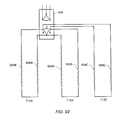
- FIG. 92 depicts an embodiment of three diads coupled to a three-phase transformer.
- FIG. 93 depicts an embodiment of groups of diads in a hexagonal pattern.
- FIG. 94 depicts an embodiment of diads in a triangular pattern.
- FIG. 95 depicts a side-view representation of an embodiment of substantially u-shaped heaters.
- FIG. 96 depicts a representational top view of an embodiment of a surface pattern of heaters depicted in FIG. 95 .
- FIG. 97 depicts a cross-sectional representation of substantially u-shaped heaters in a hydrocarbon layer.
- FIG. 98 depicts a side view representation of an embodiment of substantially vertical heaters coupled to a substantially horizontal wellbore.
- FIG. 99 depicts an embodiment of pluralities of substantially horizontal heaters coupled to bus bars in a hydrocarbon layer
- FIG. 100 depicts an alternative embodiment of pluralities of substantially horizontal heaters coupled to bus bars in a hydrocarbon layer.
- FIG. 101 depicts an enlarged view of an embodiment of a bus bar coupled to heater with connectors.
- FIG. 102 depicts an enlarged view of an embodiment of a bus bar coupled to a heater with connectors and centralizers.
- FIG. 103 depicts a cross-sectional representation of a connector coupling to a bus bar.
- FIG. 104 depicts a three-dimensional representation of a connector coupling to a bus bar.
- FIG. 105 depicts an embodiment of a substantially u-shaped heater that electrically isolates itself from the formation.
- FIG. 106 depicts an embodiment of a single-ended, substantially horizontal heater that electrically isolates itself from the formation.
- FIG. 107 depicts an embodiment of a single-ended, substantially horizontal heater that electrically isolates itself from the formation using an insulated conductor as the center conductor.
- FIG. 108 depicts an embodiment of a single-ended, substantially horizontal insulated conductor heater that electrically isolates itself from the formation.
- FIGS. 109A and 109B depict cross-sectional representations of an embodiment of an insulated conductor that is electrically isolated on the outside of the jacket.
- FIGS. 110A and 110B depict an embodiment for using substantially u-shaped wellbores to time sequence heat two layers in a hydrocarbon containing formation.
- FIGS. 111A and 111B depict an embodiment for using horizontal wellbores to time sequence heat two layers in a hydrocarbon containing formation.
- FIG. 112 depicts an embodiment of a wellhead.
- FIG. 113 depicts an embodiment of a dual continuous tubular suspension mechanism including threads cut on the dual continuous tubular over a built up portion.
- FIG. 114 depicts an embodiment of a dual continuous tubular suspension mechanism including a built up portion on a continuous tubular.
- FIGS. 115A-B depict embodiments of dual continuous tubular suspension mechanisms including slip mechanisms.
- FIG. 116 depicts an embodiment of a dual continuous tubular suspension mechanism including a slip mechanism and a screw lock system.
- FIG. 117 depicts an embodiment of a dual continuous tubular suspension mechanism including a slip mechanism and a screw lock system with counter sunk bolts.
- FIG. 118 depicts an embodiment of a pass-through fitting used to suspend tubulars.
- FIG. 119 depicts an embodiment of a dual slip mechanism for inhibiting movement of tubulars.
- FIG. 120A-B depict embodiments of split suspension mechanisms and split slip assemblies for hanging dual continuous tubulars.
- FIG. 121 depicts an embodiment of a dual slip mechanism for inhibiting movement of tubulars with a reverse configuration.
- FIG. 122 depicts an embodiment of a two-part dual slip mechanism for inhibiting movement of tubulars.
- FIG. 123 depicts an embodiment of a two-part dual slip mechanism for inhibiting movement of tubulars with separate locks.
- FIG. 124 depicts an embodiment of a dual slip mechanism locking plate for inhibiting movement of tubulars.
- FIG. 125 depicts an embodiment of a segmented dual slip mechanism with locking screws for inhibiting movement of tubulars.
- FIG. 126 depicts a top view representation of the embodiment of a transformer showing the windings and core of the transformer.
- FIG. 127 depicts a side view representation of the embodiment of the transformer showing the windings, the core, and the power leads.
- FIG. 128 depicts an embodiment of a transformer in a wellbore.
- FIG. 129 depicts an embodiment of a transformer in a wellbore with heat pipes.
- FIG. 130 depicts a side view representation of an embodiment for producing mobilized fluids from a tar sands formation with a relatively thin hydrocarbon layer.
- FIG. 131 depicts a side view representation of an embodiment for producing mobilized fluids from a tar sands formation with a hydrocarbon layer that is thicker than the hydrocarbon layer depicted in FIG. 130 .
- FIG. 132 depicts a side view representation of an embodiment for producing mobilized fluids from a tar sands formation with a hydrocarbon layer that is thicker than the hydrocarbon layer depicted in FIG. 131 .
- FIG. 133 depicts a side view representation of an embodiment for producing mobilized fluids from a tar sands formation with a hydrocarbon layer that has a shale break.
- FIG. 134 depicts a top view representation of an embodiment for preheating using heaters for the drive process.
- FIG. 135 depicts a side view representation of an embodiment for preheating using heaters for the drive process.
- FIG. 136 depicts a representation of an embodiment for producing hydrocarbons from a tar sands formation.
- FIG. 137 depicts a representation of an embodiment for producing hydrocarbons from multiple layers in a tar sands formation.
- FIG. 138 depicts an embodiment for heating and producing from a formation with a temperature limited heater in a production wellbore.
- FIG. 139 depicts an embodiment for heating and producing from a formation with a temperature limited heater and a production wellbore.
- FIG. 140 depicts an embodiment of a heating/production assembly that may be located in a wellbore for gas lifting.
- FIG. 141 depicts an embodiment of a heating/production assembly that may be located in a wellbore for gas lifting.
- FIG. 142 depicts another embodiment of a heating/production assembly that may be located in a wellbore for gas lifting.
- FIG. 143 depicts an embodiment of a production conduit and a heater.
- FIG. 144 depicts an embodiment for treating a formation.
- FIG. 145 depicts an embodiment of a heater well with selective heating.
- FIG. 146 depicts a schematic representation of an embodiment of a downhole oxidizer assembly.
- FIG. 147 depicts a cross-sectional representation of an embodiment of a downhole oxidizer including an insulating sleeve.
- FIG. 148 depicts a cross-sectional representation of an embodiment of a downhole oxidizer with a gas cooled insulating sleeve.
- FIG. 149 depicts a perspective view of an embodiment of a portion of an oxidizer of a downhole oxidizer assembly.
- FIG. 150 depicts a cross-sectional representation of an embodiment of an oxidizer shield.
- FIG. 151 depicts a cross-sectional representation of an embodiment of an oxidizer shield.
- FIG. 152 depicts a cross-sectional representation of an embodiment of an oxidizer shield.
- FIG. 153 depicts a cross-sectional representation of an embodiment of an oxidizer shield.
- FIG. 154 depicts a cross-sectional representation of an embodiment of an oxidizer shield with multiple flame stabilizers.
- FIG. 155 depicts a cross-sectional representation of an embodiment of an oxidizer shield.
- FIG. 156 depicts a perspective representation of an embodiment of a sectioned oxidizer.
- FIG. 157 depicts a perspective representation of an embodiment of a sectioned oxidizer.
- FIG. 158 depicts a perspective representation of an embodiment of a sectioned oxidizer.
- FIG. 159 depicts a perspective representation of an embodiment of a portion of an oxidizer of a downhole oxidizer assembly with louvered openings in the shield.
- FIG. 160 depicts a cross-sectional representation of a portion of a shield with a louvered opening.
- FIG. 161 depicts a cross-sectional representation of an embodiment of a first oxidizer of an oxidizer assembly.
- FIG. 162 depicts a cross-sectional representation of an embodiment of a catalytic burner.
- FIG. 163 depicts a cross-sectional representation of an embodiment of a catalytic burner with an igniter.
- FIG. 164 depicts a schematic representation of an embodiment of a heater that uses coal as fuel.
- FIG. 165 depicts a schematic representation of an embodiment of a heater that uses coal as fuel.
- FIG. 166 depicts a schematic representation of a closed loop circulation system for heating a portion of a formation.
- FIG. 167 depicts a plan view of wellbore entries and exits from a portion of a formation to be heated using a closed loop circulation system.
- FIG. 168 depicts a schematic representation of an embodiment of an in situ heat treatment system that uses a nuclear reactor.
- FIG. 169 depicts an elevational view of an in situ heat treatment system using pebble bed reactors.
- FIG. 170 depicts a schematic of an embodiment of a U-shaped nuclear heater assembly.
- FIG. 171 depicts a schematic of an embodiment of a nuclear heater assembly.
- FIG. 172 depicts a schematic an embodiment of a middle portion of a nuclear heater assembly that includes pebble reactors and nuclear moderators.
- FIG. 173 depicts a schematic of an embodiment of an end portion of a nuclear heater assembly that includes pebble reactors and nuclear moderators.
- FIG. 174 depicts a schematic of an embodiment of a nuclear heater assembly that includes pebble reactors and spacers.
- FIG. 175 depicts a schematic an embodiment of a nuclear heater assembly that includes stacked pebble reactors.
- FIG. 176 depicts a schematic an embodiment of an embodiment of nuclear heater assembly.
- FIG. 177 depicts a side view representation of an embodiment of a system for heating the formation that can use a closed loop circulation system and/or electrical heating.
- FIG. 178 depicts a side view representation of an embodiment for an in situ staged heating and producing process for treating a tar sands formation.
- FIG. 179 depicts a top view of a rectangular checkerboard pattern embodiment for the in situ staged heating and production process.
- FIG. 180 depicts a top view of a ring pattern embodiment for the in situ staged heating and production process.
- FIG. 181 depicts a top view of a checkerboard ring pattern embodiment for the in situ staged heating and production process.
- FIG. 182 depicts a top view an embodiment of a plurality of rectangular checkerboard patterns in a treatment area for the in situ staged heating and production process.
- FIG. 183 depicts a side view representations of embodiments for producing mobilized fluids from a hydrocarbon formation.
- FIG. 184 depicts a schematic representation of a system for inhibiting migration of formation fluid from a treatment area.
- FIG. 185 depicts an embodiment of a windmill for generating electricity for subsurface heaters.
- FIG. 186 depicts an embodiment of a solution mining well.
- FIG. 187 depicts a representation of a portion of a solution mining well.
- FIG. 188 depicts a representation of a portion of a solution mining well.
- FIG. 189 depicts an elevational view of a well pattern for solution mining and/or an in situ heat treatment process.
- FIG. 190 depicts a representation of wells of an in situ heating treatment process for solution mining and producing hydrocarbons from a formation.
- FIG. 191 depicts an embodiment for solution mining a formation.
- FIG. 192 depicts an embodiment of a formation with nahcolite layers in the formation before solution mining nahcolite from the formation.
- FIG. 193 depicts the formation of FIG. 192 after the nahcolite has been solution mined.
- FIG. 194 depicts an embodiment of two injection wells interconnected by a zone that has been solution mined to remove nahcolite from the zone.
- FIG. 195 depicts an embodiment for heating a formation with dawsonite in the formation.
- FIG. 196 depicts a representation of an embodiment for solution mining with a steam and electricity cogeneration facility.
- FIG. 197 depicts an embodiment of treating a hydrocarbon containing formation with a combustion front.
- FIG. 198 depicts a cross-sectional view of an embodiment of treating a hydrocarbon containing formation with a combustion front.
- FIG. 199 depicts a schematic representation of a system for producing formation fluid and introducing sour gas into a subsurface formation.
- FIG. 200 depicts electrical resistance versus temperature at various applied electrical currents for a 446 stainless steel rod.
- FIG. 201 shows resistance profiles as a function of temperature at various applied electrical currents for a copper rod contained in a conduit of Sumitomo HCM12A.
- FIG. 202 depicts electrical resistance versus temperature at various applied electrical currents for a temperature limited heater.
- FIG. 203 depicts raw data for a temperature limited heater.
- FIG. 204 depicts electrical resistance versus temperature at various applied electrical currents for a temperature limited heater.
- FIG. 205 depicts power versus temperature at various applied electrical currents for a temperature limited heater.
- FIG. 206 depicts electrical resistance versus temperature at various applied electrical currents for a temperature limited heater.
- FIG. 207 depicts data of electrical resistance versus temperature for a solid 2.54 cm diameter, 1.8 m long 410 stainless steel rod at various applied electrical currents.
- FIG. 208 depicts data of electrical resistance versus temperature for a composite 1.9 cm, 1.8 m long alloy 42-6 rod with a copper core (the rod has an outside diameter to copper diameter ratio of 2:1) at various applied electrical currents.
- FIG. 209 depicts data of power output versus temperature for a composite 1.9 cm, 1.8 m long alloy 42-6 rod with a copper core (the rod has an outside diameter to copper diameter ratio of 2:1) at various applied electrical currents.
- FIG. 210 depicts data for values of skin depth versus temperature for a solid 2.54 cm diameter, 1.8 m long 410 stainless steel rod at various applied AC electrical currents.
- FIG. 211 depicts temperature versus time for a temperature limited heater.
- FIG. 212 depicts temperature versus log time data for a 2.5 cm solid 410 stainless steel rod and a 2.5 cm solid 304 stainless steel rod.
- FIG. 213 depicts experimentally measured resistance versus temperature at several currents for a temperature limited heater with a copper core, a carbon steel ferromagnetic conductor, and a 347H stainless steel support member.
- FIG. 214 depicts experimentally measured resistance versus temperature at several currents for a temperature limited heater with a copper core, an iron-cobalt ferromagnetic conductor, and a 347H stainless steel support member.
- FIG. 215 depicts experimentally measured power factor versus temperature at two AC currents for a temperature limited heater with a copper core, a carbon steel ferromagnetic conductor, and a 347H stainless steel support member.
- FIG. 216 depicts experimentally measured turndown ratio versus maximum power delivered for a temperature limited heater with a copper core, a carbon steel ferromagnetic conductor, and a 347H stainless steel support member.
- FIG. 217 depicts examples of relative magnetic permeability versus magnetic field for both the found correlations and raw data for carbon steel.
- FIG. 218 shows the resulting plots of skin depth versus magnetic field for four temperatures and 400 A current.
- FIG. 219 shows a comparison between the experimental and numerical (calculated) results for currents of 300 A, 400 A, and 500 A.
- FIG. 220 shows the AC resistance per foot of the heater element as a function of skin depth at 1100° F. calculated from the theoretical model.
- FIG. 221 depicts the power generated per unit length in each heater component versus skin depth for a temperature limited heater.
- FIGS. 222A-C compare the results of theoretical calculations with experimental data for resistance versus temperature in a temperature limited heater.
- FIG. 223 displays temperature of the center conductor of a conductor-in-conduit heater as a function of formation depth for a Curie temperature heater with a turndown ratio of 2:1.
- FIG. 224 displays heater heat flux through a formation for a turndown ratio of 2:1 along with the oil shale richness profile.
- FIG. 225 displays heater temperature as a function of formation depth for a turndown ratio of 3:1.
- FIG. 226 displays heater heat flux through a formation for a turndown ratio of 3:1 along with the oil shale richness profile.
- FIG. 227 displays heater temperature as a function of formation depth for a turndown ratio of 4:1.
- FIG. 228 depicts heater temperature versus depth for heaters used in a simulation for heating oil shale.
- FIG. 229 depicts heater heat flux versus time for heaters used in a simulation for heating oil shale.
- FIG. 230 depicts accumulated heat input versus time in a simulation for heating oil shale.
- FIG. 231 depicts a plot of heater power versus core diameter.
- FIG. 232 depicts power, resistance, and current versus temperature for a heater with core diameters of 0.105′′.
- FIG. 233 depicts actual heater power versus time during the simulation for three different heater designs.
- FIG. 234 depicts heater element temperature (core temperature) and average formation temperature versus time for three different heater designs.
- FIG. 235 depicts cumulative gas production and cumulative oil production versus time found from a STARS simulation using the heaters and heater pattern depicted in FIGS. 70 and 72 .
- FIG. 236 depicts experimental calculations of weight percentages of ferrite and austenite phases versus temperature for iron alloy TC3.
- FIG. 237 depicts experimental calculations of weight percentages of ferrite and austenite phases versus temperature for iron alloy FM-4.
- FIG. 238 depicts the Curie temperature and phase transformation temperature range for several iron alloys.
- FIG. 239 depicts experimental calculations of weight percentages of ferrite and austenite phases versus temperature for an iron-cobalt alloy with 5.63% by weight cobalt and 0.4% by weight manganese.
- FIG. 240 depicts experimental calculations of weight percentages of ferrite and austenite phases versus temperature for an iron-cobalt alloy with 5.63% by weight cobalt, 0.4% by weight manganese, and 0.01% by weight carbon.
- FIG. 241 depicts experimental calculations of weight percentages of ferrite and austenite phases versus temperature for an iron-cobalt alloy with 5.63% by weight cobalt, 0.4% by weight manganese, and 0.085% by weight carbon.
- FIG. 242 depicts experimental calculations of weight percentages of ferrite and austenite phases versus temperature for an iron-cobalt alloy with 5.63% by weight cobalt, 0.4% by weight manganese, 0.085% by weight carbon, and 0.4% by weight titanium.
- FIG. 243 depicts experimental calculations of weight percentages of ferrite and austenite phases versus temperature for an iron-chromium alloy having 12.25% by weight chromium, 0.1% by weight carbon, 0.5% by weight manganese, and 0.5% by weight silicon.
- FIG. 244 depicts experimental calculation of weight percentages of phases versus weight percentages of chromium in an alloy.
- FIG. 245 depicts experimental calculation of weight percentages of phases versus weight percentages of silicon in an alloy.
- FIG. 246 depicts experimental calculation of weight percentages of phases versus weight percentages of tungsten in an alloy.
- FIG. 247 depicts experimental calculation of weight percentages of phases versus weight percentages of niobium in an alloy.
- FIG. 248 depicts experimental calculation of weight percentages of phases versus weight percentages of carbon in an alloy.
- FIG. 249 depicts experimental calculation of weight percentages of phases versus weight percentages of nitrogen in an alloy.
- FIG. 250 depicts experimental calculation of weight percentages of phases versus weight percentages of titanium in an alloy.
- FIG. 251 depicts experimental calculation of weight percentages of phases versus weight percentages of copper in an alloy.
- FIG. 252 depicts experimental calculation of weight percentages of phases versus weight percentages of manganese in an alloy.
- FIG. 253 depicts experimental calculation of weight percentages of phases versus weight percentages of nickel in an alloy.
- FIG. 254 depicts experimental calculation of weight percentages of phases versus weight percentages of molybdenum in an alloy.
- FIG. 255A depicts yield strengths and ultimate tensile strengths for different metals.
- FIG. 255B depicts yield strengths for different metals.
- FIG. 255C depicts ultimate tensile strengths for different metals.
- FIG. 255D depicts yield strengths for different metals.
- FIG. 255E depicts ultimate tensile strengths for different metals.
- FIG. 256 depicts projected corrosion rates over a one-year period for several metals in a sulfidation atmosphere.
- FIG. 257 depicts projected corrosion rates over a one-year period for 410 stainless steel and 410 stainless steel containing various amounts of cobalt in a sulfidation atmosphere.
- FIG. 258 depicts an example of richness of an oil shale formation (gal/ton) versus depth (ft).
- FIG. 259 depicts resistance per foot (m ⁇ /ft) versus temperature (° F.) profile of the first heater example.
- FIG. 260 depicts average temperature in the formation (° F.) versus time (days) as determined by the simulation for the first example.
- FIG. 261 depicts resistance per foot (m ⁇ /ft) versus temperature (° F.) for the second heater example.
- FIG. 262 depicts average temperature in the formation (° F.) versus time (days) as determined by the simulation for the second example.
- FIG. 263 depicts net heater energy input (Btu) versus time (days) for the second example.
- FIG. 264 depicts power injection per foot (W/ft) versus time (days) for the second example.
- FIG. 265 depicts resistance per foot (m ⁇ /ft) versus temperature (° F.) for the third heater example.
- FIG. 266 depicts average temperature in the formation (° F.) versus time (days) as determined by the simulation for the third example.
- FIG. 267 depicts cumulative energy injection (Btu) versus time (days) for each of the three heater examples.
- FIG. 268 depicts average temperature (° F.) versus time (days) for the third heater example with a 30 foot spacing between heaters in the formation as determined by the simulation.
- FIG. 269 depicts average temperature (° F.) versus time (days) for the fourth heater example using the heater configuration and pattern depicted in FIGS. 70 and 72 as determined by the simulation.
- FIG. 270 depicts a temperature profile in the formation after 360 days using the STARS simulation.
- FIG. 271 depicts an oil saturation profile in the formation after 360 days using the STARS simulation.
- FIG. 272 depicts the oil saturation profile in the formation after 1095 days using the STARS simulation.
- FIG. 273 depicts the oil saturation profile in the formation after 1470 days using the STARS simulation.
- FIG. 274 depicts the oil saturation profile in the formation after 1826 days using the STARS simulation.
- FIG. 275 depicts the temperature profile in the formation after 1826 days using the STARS simulation.
- FIG. 276 depicts oil production rate and gas production rate versus time.
- FIG. 277 depicts weight percentage of original bitumen in place (OBIP)(left axis) and volume percentage of OBIP (right axis) versus temperature (° C.).
- FIG. 278 depicts bitumen conversion percentage (weight percentage of (OBIP))(left axis) and oil, gas, and coke weight percentage (as a weight percentage of OBIP)(right axis) versus temperature (° C.).
- FIG. 279 depicts API gravity (°)(left axis) of produced fluids, blow down production, and oil left in place along with pressure (psig)(right axis) versus temperature (° C.).
- FIG. 280A-D depict gas-to-oil ratios (GOR) in thousand cubic feet per barrel ((Mcf/bbl)(y-axis) for versus temperature (° C.)(x-axis) for different types of gas at a low temperature blow down (about 277° C.) and a high temperature blow down (at about 290° C.).
- GOR gas-to-oil ratios
- FIG. 281 depicts coke yield (weight percentage)(y-axis) versus temperature (° C.)(x-axis).
- FIG. 282A-D depict assessed hydrocarbon isomer shifts in fluids produced from the experimental cells as a function of temperature and bitumen conversion.
- FIG. 283 depicts weight percentage (Wt %)(y-axis) of saturates from SARA analysis of the produced fluids versus temperature (° C.)(x-axis).
- FIG. 284 depicts weight percentage (Wt %)(y-axis) of n-C 7 of the produced fluids versus temperature (° C.)(x-axis).
- the following description generally relates to systems and methods for treating hydrocarbons in the formations. Such formations may be treated to yield hydrocarbon products, hydrogen, and other products.
- Alternating current refers to a time-varying current that reverses direction substantially sinusoidally. AC produces skin effect electricity flow in a ferromagnetic conductor.
- API gravity refers to API gravity at 15.5° C. (60° F.). API gravity is as determined by ASTM Method D6822 or ASTM Method D1298.
- ASTM refers to American Standard Testing and Materials.
- the term “automatically” means such systems, apparatus, and methods function in a certain way without the use of external control (for example, external controllers such as a controller with a temperature sensor and a feedback loop, PID controller, or predictive controller).
- external controllers such as a controller with a temperature sensor and a feedback loop, PID controller, or predictive controller.
- “Bare metal” and “exposed metal” refer to metals of elongated members that do not include a layer of electrical insulation, such as mineral insulation, that is designed to provide electrical insulation for the metal throughout an operating temperature range of the elongated member.
- Bare metal and exposed metal may encompass a metal that includes a corrosion inhibiter such as a naturally occurring oxidation layer, an applied oxidation layer, and/or a film.
- Bare metal and exposed metal include metals with polymeric or other types of electrical insulation that cannot retain electrical insulating properties at typical operating temperature of the elongated member. Such material may be placed on the metal and may be thermally degraded during use of the heater.
- Boiling range distributions for the formation fluid and liquid streams described herein are as determined by ASTM Method D5307 or ASTM Method D2887. Content of hydrocarbon components in weight percent for paraffins, iso-paraffins, olefins, naphthenes and aromatics in the liquid streams is as determined by ASTM Method D6730. Content of aromatics in volume percent is as determined by ASTM Method D1319. The weight percent of hydrogen in hydrocarbons is as determined by ASTM Method D3343.
- Carbon number refers to the number of carbon atoms in a molecule.
- a hydrocarbon fluid may include various hydrocarbons with different carbon numbers.
- the hydrocarbon fluid may be described by a carbon number distribution.
- Carbon numbers and/or carbon number distributions may be determined by true boiling point distribution and/or gas-liquid chromatography.
- “Cenospheres” refers to hollow particulate that are formed in thermal processes at high temperatures when molten components are blown up like balloons by the volatilization of organic components.
- “Chemically stability” refers to the ability of a formation fluid to be transported without components in the formation fluid reacting to form polymers and/or compositions that plug pipelines, valves, and/or vessels.
- “Clogging” refers to impeding and/or inhibiting flow of one or more compositions through a process vessel or a conduit.
- Column X element or “Column X elements” refer to one or more elements of Column X of the Periodic Table, and/or one or more compounds of one or more elements of Column X of the Periodic Table, in which X corresponds to a column number (for example, 13-18) of the Periodic Table.
- Column 15 elements refer to elements from Column 15 of the Periodic Table and/or compounds of one or more elements from Column 15 of the Periodic Table.
- Column X metal or “Column X metals” refer to one or more metals of Column X of the Periodic Table and/or one or more compounds of one or more metals of Column X of the Periodic Table, in which X corresponds to a column number (for example, 1-12) of the Periodic Table.
- Column 6 metals refer to metals from Column 6 of the Periodic Table and/or compounds of one or more metals from Column 6 of the Periodic Table.
- Condensable hydrocarbons are hydrocarbons that condense at 25° C. and one atmosphere absolute pressure. Condensable hydrocarbons may include a mixture of hydrocarbons having carbon numbers greater than 4. “Non-condensable hydrocarbons” are hydrocarbons that do not condense at 25° C. and one atmosphere absolute pressure. Non-condensable hydrocarbons may include hydrocarbons having carbon numbers less than 5.
- Coring is a process that generally includes drilling a hole into a formation and removing a substantially solid mass of the formation from the hole.
- “Cracking” refers to a process involving decomposition and molecular recombination of organic compounds to produce a greater number of molecules than were initially present. In cracking, a series of reactions take place accompanied by a transfer of hydrogen atoms between molecules. For example, naphtha may undergo a thermal cracking reaction to form ethene and H 2 .
- “Curie temperature” is the temperature above which a ferromagnetic material loses all of its ferromagnetic properties. In addition to losing all of its ferromagnetic properties above the Curie temperature, the ferromagnetic material begins to lose its ferromagnetic properties when an increasing electrical current is passed through the ferromagnetic material.
- “Cycle oil” refers to a mixture of light cycle oil and heavy cycle oil.
- Light cycle oil refers to hydrocarbons having a boiling range distribution between 430° F. (221° C.) and 650° F. (343° C.) that are produced from a fluidized catalytic cracking system. Light cycle oil content is determined by ASTM Method D5307.
- Heavy cycle oil refers to hydrocarbons having a boiling range distribution between 650° F. (343° C.) and 800° F. (427° C.) that are produced from a fluidized catalytic cracking system. Heavy cycle oil content is determined by ASTM Method D5307.
- Diad refers to a group of two items (for example, heaters, wellbores, or other objects) coupled together.
- Diesel refers to hydrocarbons with a boiling range distribution between 260° C. and 343° C. (500-650° F.) at 0.101 MPa. Diesel content is determined by ASTM Method D2887.
- Enriched air refers to air having a larger mole fraction of oxygen than air in the atmosphere. Air is typically enriched to increase combustion-supporting ability of the air.
- Fluid pressure is a pressure generated by a fluid in a formation.
- Low density pressure (sometimes referred to as “lithostatic stress”) is a pressure in a formation equal to a weight per unit area of an overlying rock mass.
- Hydrostatic pressure is a pressure in a formation exerted by a column of water.
- a “formation” includes one or more hydrocarbon containing layers, one or more non-hydrocarbon layers, an overburden, and/or an underburden.
- Hydrocarbon layers refer to layers in the formation that contain hydrocarbons.
- the hydrocarbon layers may contain non-hydrocarbon material and hydrocarbon material.
- the “overburden” and/or the “underburden” include one or more different types of impermeable materials.
- the overburden and/or underburden may include rock, shale, mudstone, or wet/tight carbonate.
- the overburden and/or the underburden may include a hydrocarbon containing layer or hydrocarbon containing layers that are relatively impermeable and are not subjected to temperatures during in situ heat treatment processing that result in significant characteristic changes of the hydrocarbon containing layers of the overburden and/or the underburden.
- the underburden may contain shale or mudstone, but the underburden is not allowed to heat to pyrolysis temperatures during the in situ heat treatment process.
- the overburden and/or the underburden may be somewhat permeable.
- Formation fluids refer to fluids present in a formation and may include pyrolyzation fluid, synthesis gas, mobilized hydrocarbon, and water (steam). Formation fluids may include hydrocarbon fluids as well as non-hydrocarbon fluids.
- the term “mobilized fluid” refers to fluids in a hydrocarbon containing formation that are able to flow as a result of thermal treatment of the formation.
- Produced fluids refer to fluids removed from the formation.
- Freezing point of a hydrocarbon liquid refers to the temperature below which solid hydrocarbon crystals may form in the liquid. Freezing point is as determined by ASTM Method D5901.
- Gasoline hydrocarbons refer to hydrocarbons having a boiling point range from 32° C. (90° F.) to about 204° C. (400° F.). Gasoline hydrocarbons include, but are not limited to, straight run gasoline, naphtha, fluidized or thermally catalytically cracked gasoline, VB gasoline, and coker gasoline. Gasoline hydrocarbons content is determined by ASTM Method D2887.
- Heat of Combustion refers to an estimation of the net heat of combustion of a liquid. Heat of combustion is as determined by ASTM Method D3338.
- a “heat source” is any system for providing heat to at least a portion of a formation substantially by conductive and/or radiative heat transfer.
- a heat source may include electric heaters such as an insulated conductor, an elongated member, and/or a conductor disposed in a conduit.
- a heat source may also include systems that generate heat by burning a fuel external to or in a formation. The systems may be surface burners, downhole gas burners, flameless distributed combustors, and natural distributed combustors.
- heat provided to or generated in one or more heat sources may be supplied by other sources of energy. The other sources of energy may directly heat a formation, or the energy may be applied to a transfer medium that directly or indirectly heats the formation.
- one or more heat sources that are applying heat to a formation may use different sources of energy.
- some heat sources may supply heat from electric resistance heaters, some heat sources may provide heat from combustion, and some heat sources may provide heat from one or more other energy sources (for example, chemical reactions, solar energy, wind energy, biomass, or other sources of renewable energy).
- a chemical reaction may include an exothermic reaction (for example, an oxidation reaction).
- a heat source may also include a heater that provides heat to a zone proximate and/or surrounding a heating location such as a heater well.
- a “heater” is any system or heat source for generating heat in a well or a near wellbore region.
- Heaters may be, but are not limited to, electric heaters, burners, combustors that react with material in or produced from a formation, and/or combinations thereof.
- Heavy hydrocarbons are viscous hydrocarbon fluids. Heavy hydrocarbons may include highly viscous hydrocarbon fluids such as heavy oil, tar, and/or asphalt. Heavy hydrocarbons may include carbon and hydrogen, as well as smaller concentrations of sulfur, oxygen, and nitrogen. Additional elements may also be present in heavy hydrocarbons in trace amounts. Heavy hydrocarbons may be classified by API gravity. Heavy hydrocarbons generally have an API gravity below about 20°. Heavy oil, for example, generally has an API gravity of about 10-20°, whereas tar generally has an API gravity below about 10°. The viscosity of heavy hydrocarbons is generally greater than about 100 centipoise at 15° C. Heavy hydrocarbons may include aromatics or other complex ring hydrocarbons.
- Heavy hydrocarbons may be found in a relatively permeable formation.
- the relatively permeable formation may include heavy hydrocarbons entrained in, for example, sand or carbonate.
- “Relatively permeable” is defined, with respect to formations or portions thereof, as an average permeability of 10 millidarcy or more (for example, 10 or 100 millidarcy).
- “Relatively low permeability” is defined, with respect to formations or portions thereof, as an average permeability of less than about 10 millidarcy.
- One darcy is equal to about 0.99 square micrometers.
- An impermeable layer generally has a permeability of less than about 0.1 millidarcy.
- Certain types of formations that include heavy hydrocarbons may also be, but are not limited to, natural mineral waxes, or natural asphaltites.
- Natural mineral waxes typically occur in substantially tubular veins that may be several meters wide, several kilometers long, and hundreds of meters deep.
- Natural asphaltites include solid hydrocarbons of an aromatic composition and typically occur in large veins.
- In situ recovery of hydrocarbons from formations such as natural mineral waxes and natural asphaltites may include melting to form liquid hydrocarbons and/or solution mining of hydrocarbons from the formations.
- Hydrocarbons are generally defined as molecules formed primarily by carbon and hydrogen atoms. Hydrocarbons may also include other elements such as, but not limited to, halogens, metallic elements, nitrogen, oxygen, and/or sulfur. Hydrocarbons may be, but are not limited to, kerogen, bitumen, pyrobitumen, oils, natural mineral waxes, and asphaltites. Hydrocarbons may be located in or adjacent to mineral matrices in the earth. Matrices may include, but are not limited to, sedimentary rock, sands, silicilytes, carbonates, diatomites, and other porous media. “Hydrocarbon fluids” are fluids that include hydrocarbons. Hydrocarbon fluids may include, entrain, or be entrained in non-hydrocarbon fluids such as hydrogen, nitrogen, carbon monoxide, carbon dioxide, hydrogen sulfide, water, and ammonia.
- An “in situ conversion process” refers to a process of heating a hydrocarbon containing formation from heat sources to raise the temperature of at least a portion of the formation above a pyrolysis temperature so that pyrolyzation fluid is produced in the formation.
- An “in situ heat treatment process” refers to a process of heating a hydrocarbon containing formation with heat sources to raise the temperature of at least a portion of the formation above a temperature that results in mobilized fluid, visbreaking, and/or pyrolysis of hydrocarbon containing material so that mobilized fluids, visbroken fluids, and/or pyrolyzation fluids are produced in the formation.
- Insulated conductor refers to any elongated material that is able to conduct electricity and that is covered, in whole or in part, by an electrically insulating material.
- “Karst” is a subsurface shaped by the dissolution of a soluble layer or layers of bedrock, usually carbonate rock such as limestone or dolomite.
- the dissolution may be caused by meteoric or acidic water.
- the Grosmont formation in Alberta, Canada is an example of a karst (or “karsted”) carbonate formation.
- Kerogen is a solid, insoluble hydrocarbon that has been converted by natural degradation and that principally contains carbon, hydrogen, nitrogen, oxygen, and sulfur. Coal and oil shale are typical examples of materials that contain kerogen.
- Biten is a non-crystalline solid or viscous hydrocarbon material that is substantially soluble in carbon disulfide.
- Oil is a fluid containing a mixture of condensable hydrocarbons.
- Kerosene refers to hydrocarbons with a boiling range distribution between 204° C. and 260° C. at 0.101 MPa. Kerosene content is determined by ASTM Method D2887.
- Modulated direct current refers to any substantially non-sinusoidal time-varying current that produces skin effect electricity flow in a ferromagnetic conductor.
- Naphtha refers to hydrocarbon components with a boiling range distribution between 38° C. and 200° C. at 0.101 MPa. Naphtha content is determined by ASTM Method D5307.
- Nitride refers to a compound of nitrogen and one or more other elements of the Periodic Table. Nitrides include, but are not limited to, silicon nitride, boron nitride, or alumina nitride.
- Nitrogen compound content refers to an amount of nitrogen in an organic compound. Nitrogen content is as determined by ASTM Method D5762.
- Optane Number refers to a calculated numerical representation of the antiknock properties of a motor fuel compared to a standard reference fuel. A calculated octane number is determined by ASTM Method D6730.
- Olefins are molecules that include unsaturated hydrocarbons having one or more non-aromatic carbon-carbon double bonds.
- Openings refer to openings, such as openings in conduits, having a wide variety of sizes and cross-sectional shapes including, but not limited to, circles, ovals, squares, rectangles, triangles, slits, or other regular or irregular shapes.
- “Pebble” refers to one or more spheres, oval shapes, oblong shapes, irregular or elongated shapes.
- Periodic Table refers to the Periodic Table as specified by the International Union of Pure and Applied Chemistry (IUPAC), November 2003.
- weight of a metal from the Periodic Table, weight of a compound of a metal from the Periodic Table, weight of an element from the Periodic Table, or weight of a compound of an element from the Periodic Table is calculated as the weight of metal or the weight of element. For example, if 0.1 grams of MoO 3 is used per gram of catalyst, the calculated weight of the molybdenum metal in the catalyst is 0.067 grams per gram of catalyst.
- Physical stability refers the ability of a formation fluid to not exhibit phase separation or flocculation during transportation of the fluid. Physical stability is determined by ASTM Method D7060.
- Pyrolysis is the breaking of chemical bonds due to the application of heat.
- pyrolysis may include transforming a compound into one or more other substances by heat alone. Heat may be transferred to a section of the formation to cause pyrolysis.
- “Pyrolyzation fluids” or “pyrolysis products” refers to fluid produced substantially during pyrolysis of hydrocarbons. Fluid produced by pyrolysis reactions may mix with other fluids in a formation. The mixture would be considered pyrolyzation fluid or pyrolyzation product.
- “pyrolysis zone” refers to a volume of a formation (for example, a relatively permeable formation such as a tar sands formation) that is reacted or reacting to form a pyrolyzation fluid.
- Residue refers to hydrocarbons that have a boiling point above 537° C. (1000° F.).
- “Rich layers” in a hydrocarbon containing formation are relatively thin layers (typically about 0.2 m to about 0.5 m thick). Rich layers generally have a richness of about 0.150 L/kg or greater. Some rich layers have a richness of about 0.170 L/kg or greater, of about 0.190 L/kg or greater, or of about 0.210 L/kg or greater. Lean layers of the formation have a richness of about 0.100 L/kg or less and are generally thicker than rich layers. The richness and locations of layers are determined, for example, by coring and subsequent Fischer assay of the core, density or neutron logging, or other logging methods. Rich layers may have a lower initial thermal conductivity than other layers of the formation. Typically, rich layers have a thermal conductivity 1.5 times to 3 times lower than the thermal conductivity of lean layers. In addition, rich layers have a higher thermal expansion coefficient than lean layers of the formation.
- Smart well technology or “smart wellbore” refers to wells that incorporate downhole measurement and/or control.
- smart well technology may allow for controlled injection of fluid into the formation in desired zones.
- smart well technology may allow for controlled production of formation fluid from selected zones.
- Some wells may include smart well technology that allows for formation fluid production from selected zones and simultaneous or staggered solution injection into other zones.
- Smart well technology may include fiber optic systems and control valves in the wellbore.
- a smart wellbore used for an in situ heat treatment process may be Westbay Multilevel Well System MP55 available from Westbay Instruments Inc. (Burnaby, British Columbia, Canada).
- Subsidence is a downward movement of a portion of a formation relative to an initial elevation of the surface.
- Sulfur compound content refers to an amount of sulfur in an organic compound. Sulfur content is as determined by ASTM Method D4294.
- Superposition of heat refers to providing heat from two or more heat sources to a selected section of a formation such that the temperature of the formation at least at one location between the heat sources is influenced by the heat sources.
- Synthesis gas is a mixture including hydrogen and carbon monoxide. Additional components of synthesis gas may include water, carbon dioxide, nitrogen, methane, and other gases. Synthesis gas may be generated by a variety of processes and feedstocks. Synthesis gas may be used for synthesizing a wide range of compounds.
- TAN refers to a total acid number expressed as milligrams (“mg”) of KOH per gram (“g”) of sample. TAN is as determined by ASTM Method D3242.
- “Tar” is a viscous hydrocarbon that generally has a viscosity greater than about 10,000 centipoise at 15° C.
- the specific gravity of tar generally is greater than 1.000.
- Tar may have an API gravity less than 10°.
- a “tar sands formation” is a formation in which hydrocarbons are predominantly present in the form of heavy hydrocarbons and/or tar entrained in a mineral grain framework or other host lithology (for example, sand or carbonate).
- Examples of tar sands formations include formations such as the Athabasca formation, the Grosmont formation, and the Peace River formation, all three in Alberta, Canada; and the Faja formation in the Orinoco belt in Venezuela.
- Temperature limited heater generally refers to a heater that regulates heat output (for example, reduces heat output) above a specified temperature without the use of external controls such as temperature controllers, power regulators, rectifiers, or other devices. Temperature limited heaters may be AC (alternating current) or modulated (for example, “chopped”) DC (direct current) powered electrical resistance heaters.
- “Thermally conductive fluid” includes fluid that has a higher thermal conductivity than air at standard temperature and pressure (STP) (0° C. and 101.325 kPa).
- Thermal conductivity is a property of a material that describes the rate at which heat flows, in steady state, between two surfaces of the material for a given temperature difference between the two surfaces.
- Thermal fracture refers to fractures created in a formation caused by expansion or contraction of a formation and/or fluids in the formation, which is in turn caused by increasing/decreasing the temperature of the formation and/or fluids in the formation, and/or by increasing/decreasing a pressure of fluids in the formation due to heating.
- Thermal Oxidation stability refers to thermal oxidation stability of a liquid. Thermal Oxidation Stability is as determined by ASTM Method D3241.
- Thickness of a layer refers to the thickness of a cross section of the layer, wherein the cross section is normal to a face of the layer.
- Time-varying current refers to electrical current that produces skin effect electricity flow in a ferromagnetic conductor and has a magnitude that varies with time. Time-varying current includes both alternating current (AC) and modulated direct current (DC).
- AC alternating current
- DC modulated direct current
- Triad refers to a group of three items (for example, heaters, wellbores, or other objects) coupled together.
- “Turndown ratio” for the temperature limited heater is the ratio of the highest AC or modulated DC resistance below the Curie temperature to the lowest resistance above the Curie temperature for a given current.
- a “u-shaped wellbore” refers to a wellbore that extends from a first opening in the formation, through at least a portion of the formation, and out through a second opening in the formation.
- the wellbore may be only roughly in the shape of a “v” or “u”, with the understanding that the “legs” of the “u” do not need to be parallel to each other, or perpendicular to the “bottom” of the “u” for the wellbore to be considered “u-shaped”.
- “Upgrade” refers to increasing the quality of hydrocarbons. For example, upgrading heavy hydrocarbons may result in an increase in the API gravity of the heavy hydrocarbons.
- “Visbreaking” refers to the untangling of molecules in fluid during heat treatment and/or to the breaking of large molecules into smaller molecules during heat treatment, which results in a reduction of the viscosity of the fluid.
- Viscosity refers to kinematic viscosity at 40° C. unless specified. Viscosity is as determined by ASTM Method D445.
- VGO or “vacuum gas oil” refers to hydrocarbons with a boiling range distribution between 343° C. and 538° C. at 0.101 MPa. VGO content is determined by ASTM Method D5307.
- a “vug” is a cavity, void or large pore in a rock that is commonly lined with mineral precipitates.
- Wax refers to a low melting organic mixture, or a compound of high molecular weight that is a solid at lower temperatures and a liquid at higher temperatures, and when in solid form can form a barrier to water.
- waxes include animal waxes, vegetable waxes, mineral waxes, petroleum waxes, and synthetic waxes.
- wellbore refers to a hole in a formation made by drilling or insertion of a conduit into the formation.
- a wellbore may have a substantially circular cross section, or another cross-sectional shape.
- wellbore and opening when referring to an opening in the formation may be used interchangeably with the term “wellbore.”
- Hydrocarbons in formations may be treated in various ways to produce many different products.
- hydrocarbons in formations are treated in stages.
- FIG. 1 depicts an illustration of stages of heating the hydrocarbon containing formation.
- FIG. 1 also depicts an example of yield (“Y”) in barrels of oil equivalent per ton (y axis) of formation fluids from the formation versus temperature (“T”) of the heated formation in degrees Celsius (x axis).
- Desorption of methane and vaporization of water occurs during stage 1 heating. Heating of the formation through stage 1 may be performed as quickly as possible. For example, when the hydrocarbon containing formation is initially heated, hydrocarbons in the formation desorb adsorbed methane. The desorbed methane may be produced from the formation. If the hydrocarbon containing formation is heated further, water in the hydrocarbon containing formation is vaporized. Water may occupy, in some hydrocarbon containing formations, between 10% and 50% of the pore volume in the formation. In other formations, water occupies larger or smaller portions of the pore volume. Water typically is vaporized in a formation between 160° C. and 285° C. at pressures of 600 kPa absolute to 7000 kPa absolute.
- the vaporized water produces wettability changes in the formation and/or increased formation pressure.
- the wettability changes and/or increased pressure may affect pyrolysis reactions or other reactions in the formation.
- the vaporized water is produced from the formation.
- the vaporized water is used for steam extraction and/or distillation in the formation or outside the formation. Removing the water from and increasing the pore volume in the formation increases the storage space for hydrocarbons in the pore volume.
- the formation is heated further, such that a temperature in the formation reaches (at least) an initial pyrolyzation temperature (such as a temperature at the lower end of the temperature range shown as stage 2 ).
- Hydrocarbons in the formation may be pyrolyzed throughout stage 2 .
- a pyrolysis temperature range varies depending on the types of hydrocarbons in the formation.
- the pyrolysis temperature range may include temperatures between 250° C. and 900° C.
- the pyrolysis temperature range for producing desired products may extend through only a portion of the total pyrolysis temperature range.
- the pyrolysis temperature range for producing desired products may include temperatures between 250° C. and 400° C. or temperatures between 270° C. and 350° C.
- a temperature of hydrocarbons in the formation is slowly raised through the temperature range from 250° C. to 400° C.
- production of pyrolysis products may be substantially complete when the temperature approaches 400° C.
- Average temperature of the hydrocarbons may be raised at a rate of less than 5° C. per day, less than 2° C. per day, less than 1° C. per day, or less than 0.5° C. per day through the pyrolysis temperature range for producing desired products.
- Heating the hydrocarbon containing formation with a plurality of heat sources may establish thermal gradients around the heat sources that slowly raise the temperature of hydrocarbons in the formation through the pyrolysis temperature range.
- the rate of temperature increase through the pyrolysis temperature range for desired products may affect the quality and quantity of the formation fluids produced from the hydrocarbon containing formation. Raising the temperature slowly through the pyrolysis temperature range for desired products may inhibit mobilization of large chain molecules in the formation. Raising the temperature slowly through the pyrolysis temperature range for desired products may limit reactions between mobilized hydrocarbons that produce undesired products. Slowly raising the temperature of the formation through the pyrolysis temperature range for desired products may allow for the production of high quality, high API gravity hydrocarbons from the formation. Slowly raising the temperature of the formation through the pyrolysis temperature range for desired products may allow for the removal of a large amount of the hydrocarbons present in the formation as hydrocarbon product.
- a portion of the formation is heated to a desired temperature instead of slowly heating the temperature through a temperature range.
- the desired temperature is 300° C., 325° C., or 350° C. Other temperatures may be selected as the desired temperature.
- Superposition of heat from heat sources allows the desired temperature to be relatively quickly and efficiently established in the formation. Energy input into the formation from the heat sources may be adjusted to maintain the temperature in the formation substantially at the desired temperature. The heated portion of the formation is maintained substantially at the desired temperature until pyrolysis declines such that production of desired formation fluids from the formation becomes uneconomical.
- Parts of the formation that are subjected to pyrolysis may include regions brought into a pyrolysis temperature range by heat transfer from only one heat source.
- formation fluids including pyrolyzation fluids are produced from the formation.
- the amount of condensable hydrocarbons in the produced formation fluid may decrease.
- the formation may produce mostly methane and/or hydrogen. If the hydrocarbon containing formation is heated throughout an entire pyrolysis range, the formation may produce only small amounts of hydrogen towards an upper limit of the pyrolysis range. After all of the available hydrogen is depleted, a minimal amount of fluid production from the formation will typically occur.
- Synthesis gas generation may take place during stage 3 heating depicted in FIG. 1 .
- Stage 3 may include heating a hydrocarbon containing formation to a temperature sufficient to allow synthesis gas generation.
- synthesis gas may be produced in a temperature range from about 400° C. to about 1200° C., about 500° C. to about 1100° C., or about 550° C. to about 1000° C.
- the temperature of the heated portion of the formation when the synthesis gas generating fluid is introduced to the formation determines the composition of synthesis gas produced in the formation.
- the generated synthesis gas may be removed from the formation through a production well or production wells.
- Total energy content of fluids produced from the hydrocarbon containing formation may stay relatively constant throughout pyrolysis and synthesis gas generation.
- a significant portion of the produced fluid may be condensable hydrocarbons that have a high energy content.
- less of the formation fluid may include condensable hydrocarbons.
- More non-condensable formation fluids may be produced from the formation.
- Energy content per unit volume of the produced fluid may decline slightly during generation of predominantly non-condensable formation fluids.
- energy content per unit volume of produced synthesis gas declines significantly compared to energy content of pyrolyzation fluid. The volume of the produced synthesis gas, however, will in many instances increase substantially, thereby compensating for the decreased energy content.
- FIG. 2 depicts a schematic view of an embodiment of a portion of the in situ heat treatment system for treating the hydrocarbon containing formation.
- the in situ heat treatment system may include barrier wells 200 .
- Barrier wells are used to form a barrier around a treatment area. The barrier inhibits fluid flow into and/or out of the treatment area.
- Barrier wells include, but are not limited to, dewatering wells, vacuum wells, capture wells, injection wells, grout wells, freeze wells, or combinations thereof.
- barrier wells 200 are dewatering wells. Dewatering wells may remove liquid water and/or inhibit liquid water from entering a portion of the formation to be heated, or to the formation being heated.
- the barrier wells 200 are shown extending only along one side of heat sources 202 , but the barrier wells typically encircle all heat sources 202 used, or to be used, to heat a treatment area of the formation.
- Heat sources 202 are placed in at least a portion of the formation.
- Heat sources 202 may include heaters such as insulated conductors, conductor-in-conduit heaters, surface burners, flameless distributed combustors, and/or natural distributed combustors. Heat sources 202 may also include other types of heaters. Heat sources 202 provide heat to at least a portion of the formation to heat hydrocarbons in the formation. Energy may be supplied to heat sources 202 through supply lines 204 .
- Supply lines 204 may be structurally different depending on the type of heat source or heat sources used to heat the formation.
- Supply lines 204 for heat sources may transmit electricity for electric heaters, may transport fuel for combustors, or may transport heat exchange fluid that is circulated in the formation.
- electricity for an in situ heat treatment process may be provided by a nuclear power plant or nuclear power plants. The use of nuclear power may allow for reduction or elimination of carbon dioxide emissions from the in situ heat treatment process.
- the heat input into the formation may cause expansion of the formation and geomechanical motion.
- the heat sources may be turned on before, at the same time, or during a dewatering process.
- Computer simulations may model formation response to heating. The computer simulations may be used to develop a pattern and time sequence for activating heat sources in the formation so that geomechanical motion of the formation does not adversely affect the functionality of heat sources, production wells, and other equipment in the formation.
- Heating the formation may cause an increase in permeability and/or porosity of the formation. Increases in permeability and/or porosity may result from a reduction of mass in the formation due to vaporization and removal of water, removal of hydrocarbons, and/or creation of fractures. Fluid may flow more easily in the heated portion of the formation because of the increased permeability and/or porosity of the formation. Fluid in the heated portion of the formation may move a considerable distance through the formation because of the increased permeability and/or porosity. The considerable distance may be over 1000 m depending on various factors, such as permeability of the formation, properties of the fluid, temperature of the formation, and pressure gradient allowing movement of the fluid. The ability of fluid to travel considerable distance in the formation allows production wells 206 to be spaced relatively far apart in the formation.
- Production wells 206 are used to remove formation fluid from the formation.
- production well 206 includes a heat source.
- the heat source in the production well may heat one or more portions of the formation at or near the production well.
- the amount of heat supplied to the formation from the production well per meter of the production well is less than the amount of heat applied to the formation from a heat source that heats the formation per meter of the heat source.
- Heat applied to the formation from the production well may increase formation permeability adjacent to the production well by vaporizing and removing liquid phase fluid adjacent to the production well and/or by increasing the permeability of the formation adjacent to the production well by formation of macro and/or micro fractures.
- More than one heat source may be positioned in the production well.
- a heat source in a lower portion of the production well may be turned off when superposition of heat from adjacent heat sources heats the formation sufficiently to counteract benefits provided by heating the formation with the production well.
- the heat source in an upper portion of the production well may remain on after the heat source in the lower portion of the production well is deactivated. The heat source in the upper portion of the well may inhibit condensation and reflux of formation fluid.
- the heat source in production well 206 allows for vapor phase removal of formation fluids from the formation.
- Providing heating at or through the production well may: (1) inhibit condensation and/or refluxing of production fluid when such production fluid is moving in the production well proximate the overburden, (2) increase heat input into the formation, (3) increase production rate from the production well as compared to a production well without a heat source, (4) inhibit condensation of high carbon number compounds (C6 and above) in the production well, and/or (5) increase formation permeability at or proximate the production well.
- Subsurface pressure in the formation may correspond to the fluid pressure generated in the formation. As temperatures in the heated portion of the formation increase, the pressure in the heated portion may increase as a result of increased fluid generation and vaporization of water. Controlling rate of fluid removal from the formation may allow for control of pressure in the formation. Pressure in the formation may be determined at a number of different locations, such as near or at production wells, near or at heat sources, or at monitor wells.
- Formation fluid may be produced from the formation when the formation fluid is of a selected quality.
- the selected quality includes an API gravity of at least about 20°, 30°, or 40°.
- Inhibiting production until at least some hydrocarbons are pyrolyzed may increase conversion of heavy hydrocarbons to light hydrocarbons. Inhibiting initial production may minimize the production of heavy hydrocarbons from the formation. Production of substantial amounts of heavy hydrocarbons may require expensive equipment and/or reduce the life of production equipment.
- hydrocarbons in the formation may be heated to pyrolysis temperatures before substantial permeability has been generated in the heated portion of the formation.
- An initial lack of permeability may inhibit the transport of generated fluids to production wells 206 .
- fluid pressure in the formation may increase proximate heat sources 202 .
- the increased fluid pressure may be released, monitored, altered, and/or controlled through one or more heat sources 202 .
- selected heat sources 202 or separate pressure relief wells may include pressure relief valves that allow for removal of some fluid from the formation.
- pressure generated by expansion of pyrolysis fluids or other fluids generated in the formation may be allowed to increase although an open path to production wells 206 or any other pressure sink may not yet exist in the formation.
- the fluid pressure may be allowed to increase towards a lithostatic pressure.
- Fractures in the hydrocarbon containing formation may form when the fluid approaches the lithostatic pressure.
- fractures may form from heat sources 202 to production wells 206 in the heated portion of the formation.
- the generation of fractures in the heated portion may relieve some of the pressure in the portion.
- Pressure in the formation may have to be maintained below a selected pressure to inhibit unwanted production, fracturing of the overburden or underburden, and/or coking of hydrocarbons in the formation.
- pressure in the formation may be varied to alter and/or control a composition of formation fluid produced, to control a percentage of condensable fluid as compared to non-condensable fluid in the formation fluid, and/or to control an API gravity of formation fluid being produced. For example, decreasing pressure may result in production of a larger condensable fluid component.
- the condensable fluid component may contain a larger percentage of olefins.
- pressure in the formation may be maintained high enough to promote production of formation fluid with an API gravity of greater than 20°. Maintaining increased pressure in the formation may inhibit formation subsidence during in situ heat treatment. Maintaining increased pressure may facilitate vapor phase production of fluids from the formation. Vapor phase production may allow for a reduction in size of collection conduits used to transport fluids produced from the formation. Maintaining increased pressure may reduce or eliminate the need to compress formation fluids at the surface to transport the fluids in collection conduits to treatment facilities.
- Maintaining increased pressure in a heated portion of the formation may surprisingly allow for production of large quantities of hydrocarbons of increased quality and of relatively low molecular weight. Pressure may be maintained so that formation fluid produced has a minimal amount of compounds above a selected carbon number.
- the selected carbon number may be at most 25, at most 20, at most 12, or at most 8.
- Some high carbon number compounds may be entrained in vapor in the formation and may be removed from the formation with the vapor. Maintaining increased pressure in the formation may inhibit entrainment of high carbon number compounds and/or multi-ring hydrocarbon compounds in the vapor.
- High carbon number compounds and/or multi-ring hydrocarbon compounds may remain in a liquid phase in the formation for significant time periods. The significant time periods may provide sufficient time for the compounds to pyrolyze to form lower carbon number compounds.
- Generation of relatively low molecular weight hydrocarbons is believed to be due, in part, to autogenous generation and reaction of hydrogen in a portion of the hydrocarbon containing formation.
- maintaining an increased pressure may force hydrogen generated during pyrolysis into the liquid phase within the formation.
- Heating the portion to a temperature in a pyrolysis temperature range may pyrolyze hydrocarbons in the formation to generate liquid phase pyrolyzation fluids.
- the generated liquid phase pyrolyzation fluids components may include double bonds and/or radicals.
- Hydrogen (H 2 ) in the liquid phase may reduce double bonds of the generated pyrolyzation fluids, thereby reducing a potential for polymerization or formation of long chain compounds from the generated pyrolyzation fluids.
- H 2 may also neutralize radicals in the generated pyrolyzation fluids. Therefore, H 2 in the liquid phase may inhibit the generated pyrolyzation fluids from reacting with each other and/or with other compounds in the formation.
- Formation fluid produced from production wells 206 may be transported through collection piping 208 to treatment facilities 210 .
- Formation fluids may also be produced from heat sources 202 .
- fluid may be produced from heat sources 202 to control pressure in the formation adjacent to the heat sources.
- Fluid produced from heat sources 202 may be transported through tubing or piping to collection piping 208 or the produced fluid may be transported through tubing or piping directly to treatment facilities 210 .
- Treatment facilities 210 may include separation units, reaction units, upgrading units, fuel cells, turbines, storage vessels, and/or other systems and units for processing produced formation fluids.
- the treatment facilities may form transportation fuel from at least a portion of the hydrocarbons produced from the formation.
- the transportation fuel may be jet fuel, such as JP-8.
- Formation fluid may be hot when produced from the formation through the production wells.
- Hot formation fluid may be produced during solution mining processes and/or during in situ heat treatment processes.
- electricity may be generated using the heat of the fluid produced from the formation.
- heat recovered from the formation after the in situ process may be used to generate electricity.
- the generated electricity may be used to supply power to the in situ heat treatment process.
- the electricity may be used to power heaters, or to power a refrigeration system for forming or maintaining a low temperature barrier. Electricity may be generated using a Kalina cycle or a modified Kalina cycle.
- FIG. 3 depicts a schematic representation of a Kalina cycle that uses relatively high pressure aqua ammonia as the working fluid.
- other fluids such as alkanes, hydrochlorofluorocarbons, hydrofluorocarbons, or carbon dioxide may be used as the working fluid.
- Hot produced fluid from the formation may pass through line 212 to heat exchanger 214 .
- the produced fluid may have a temperature greater than about 100° C.
- Line 216 from heat exchanger 214 may direct the produced fluid to a separator or other treatment unit.
- the produced fluid is a mineral containing fluid produced during solution mining.
- the produced fluid includes hydrocarbons produced using an in situ heat treatment process or using an in situ mobilization process. Heat from the produced fluid is used to evaporate aqua ammonia in heat exchanger 214 .
- Aqua ammonia from tank 218 is directed by pump 220 to heat exchanger 214 and heat exchanger 222 .
- Aqua ammonia from heat exchangers 214 , 222 passes to separator 224 .
- Separator 224 forms a rich ammonia gas stream and a lean ammonia gas stream.
- the rich ammonia gas stream is sent to turbine 226 to generate electricity.
- the lean ammonia gas stream from separator 224 passes through heat exchanger 222 .
- the lean gas stream leaving heat exchanger 222 is combined with the rich ammonia gas stream leaving turbine 226 .
- the combination stream is passed through heat exchanger 228 and returned to tank 218 .
- Heat exchanger 228 may be water cooled. Heater water from heat exchanger 228 may be sent to a surface water reservoir through line 230 .
- FIG. 4 depicts a schematic representation of a modified Kalina cycle that uses lower pressure aqua ammonia as the working fluid.
- other fluids such as alkanes, hydrochlorofluorcarbons, hydrofluorocarbons, or carbon dioxide may be used as the working fluid.
- Hot produced fluid from the formation may pass through line 212 to heat exchanger 214 .
- the produced fluid may have a temperature greater than about 100° C.
- Second heat exchanger 232 may further reduce the temperature of the produced fluid from the formation before the fluid is sent through line 216 to a separator or other treatment unit. Second heat exchanger may be water cooled.
- Aqua ammonia from tank 218 is directed by pump 220 to heat exchanger 234 .
- the temperature of the aqua ammonia from tank 218 is raised in heat exchanger 234 by heat transfer with a combined aqua ammonia stream from turbine 226 and separator 224 .
- the aqua ammonia stream from heat exchanger 234 passes to heat exchanger 236 .
- the temperature of the stream is raised again by transfer of heat with a lean ammonia stream that exits separator 224 .
- the stream then passes to heat exchanger 214 . Heat from the produced fluid is used to evaporate aqua ammonia in heat exchanger 214 .
- the aqua ammonia passes to separator 224 .
- Separator 224 forms a rich ammonia gas stream and a lean ammonia gas stream.
- the rich ammonia gas stream is sent to turbine 226 to generate electricity.
- the lean ammonia gas stream passes through heat exchanger 236 .
- the lean ammonia gas stream is combined with the rich ammonia gas stream leaving turbine 226 .
- the combined gas stream is passed through heat exchanger 234 to cooler 238 . After cooler 238 , the stream returns to tank 218 .
- Heating a portion of the subsurface formation may cause the mineral structure of the formation to change and form particles.
- the particles may be dispersed and/or become partially dissolved in the formation fluid.
- the particles may include metals and/or compounds of metals from Columns 1-2 and Columns 4-13 of the Periodic Table (for example, aluminum, silicon, magnesium, calcium, potassium sodium, beryllium, lithium, chromium, magnesium, copper, zirconium, and so forth).
- the particles include cenospheres.
- the particles are coated, for example, with hydrocarbons of the formation fluid.
- the particles include zeolites.
- a concentration of particles in formation fluid may range from about 1 ppm to about 3000 ppm, from about 50 ppm to about 2000 ppm, or from about 100 ppm to about 1000 ppm.
- the size of particles may range from about 0.5 micrometers to about 200 micrometers, from about 5 micrometers to about 150 micrometers, from about 10 micrometers to about 100 micrometers, or about 20 micrometers to about 50 micrometers.
- formation fluid may include a distribution of particles.
- the distribution of particles may be, but is not limited to, a trimodal or a bimodal distribution.
- a trimodal distribution of particles may include from about 1 ppm to about 50 ppm of particles with a size of about 5 micrometers to about 10 micrometers, from about 2 ppm to about 2000 ppm of particles with a size of about 50 micrometers to about 80 micrometers, and from about 1 ppm to about 100 ppm with a size of between about 100 micrometers and about 200 micrometers.
- a bimodal distribution of particles may include from about 1 ppm to about 60 ppm of particles with a size of between about 50 micrometers and about 60 micrometers and from about 2 ppm to about 2000 ppm of particles with a size between about 100 micrometers and about 200 micrometers.
- the particles may contact the formation fluid and catalyze formation of compounds having a carbon number of at most 25, at most 20, at most 12, or at most 8.
- zeolitic particles may assist in the oxidation and/or reduction of formation fluids to produce compounds not generally found in fluids produced using conventional production methods. Contact of formation fluid with hydrogen in the presence of zeolitic particles may catalyze reduction of double bond compounds in the formation fluid.
- all or a portion of the particles in the produced fluid may be removed from the produced fluid.
- the particles may be removed by using a centrifuge, by washing, by acid washing, by filtration, by electrostatic precipitation, by froth flotation, and/or by another type of separation process.
- Formation fluid produced from the in situ heat treatment process may be sent to the separator to split the stream into the in situ heat treatment process liquid stream and an in situ heat treatment process gas stream.
- the formation fluid has a boiling range distribution between about ⁇ 5° C. and about 350° C., between about 5° C. and about 340° C., between about 10° C. and about 330° C., or between about 15° C. and about 320° C.
- the liquid stream and the gas stream may be further treated to yield desired products.
- processing equipment may be adversely affected.
- the processing equipment may clog.
- processes to produce commercial products include, but are not limited to, alkylation, distillation, catalytic reforming hydrocracking, hydrotreating, hydrogenation, hydrodesulfurization, catalytic cracking, delayed coking, gasification, or combinations thereof.
- Processes to produce hydrocarbon streams and/or other products are described in “Refining Processes 2000,” Hydrocarbon Processing, Gulf Publishing Co., pp. 87-142, which is incorporated by reference herein.
- Examples of commercial hydrocarbon products include, but are not limited to, diesel, hydrocarbon gases, kerosene, naphtha, vacuum gas oil (“VGO”), or mixtures thereof.
- VGO vacuum gas oil
- Process equipment may become clogged or fouled by compositions in the in situ heat treatment process liquid.
- Clogging compositions may include, but are not limited to, hydrocarbons and/or solids produced from the in situ heat treatment process. Compositions that cause clogging may be formed during heating of the in situ heat treatment process liquid. The compositions may adhere to parts of the equipment and inhibit the flow of the liquid stream through processing units.
- Solids that cause clogging may include, but are not limited to, organometallic compounds, inorganic compounds, minerals, mineral compounds, cenospheres, coke, semi-soot, and/or mixtures thereof.
- the solids may have a particle size such that conventional filtration may not remove the solids from the liquid stream.
- Hydrocarbons that cause clogging may include, but are not limited to, hydrocarbons that contain heteroatoms, aromatic hydrocarbons, cyclic hydrocarbons, cyclic di-olefins, and/or acyclic di-olefins.
- solids and/or hydrocarbons present in the in situ heat treatment process liquid that cause clogging are partially soluble or insoluble in the situ heat treatment process liquid.
- conventional filtration of the liquid stream prior to or during heating is insufficient and/or ineffective for removal of all or some of the compositions that clog process equipment.
- clogging compositions are at least partially removed from the liquid stream by washing and/or desalting the liquid stream.
- clogging of process equipment is inhibited by filtering at least a portion of the liquid stream through a nanofiltration system.
- clogging of process equipment is inhibited by hydrotreating at least a portion of the liquid stream.
- at least a portion the liquid stream is nanofiltered and then hydrotreated to remove composition that may clog and/or foul process equipment.
- the hydrotreated and/or nanofiltered liquid stream may be further processed to produce commercial products.
- anti-fouling additives are added to the liquid stream to inhibit clogging of process equipment. Anti-fouling additives are described in U.S. Pat.
- Examples of commercially available additives include, but are not limited to, Chimec RO 303 Chimec RO 304, Chimec RO 305, Chimec RO 306, Chimec RO 307, Chimec RO 308, (available from Chimec, Rome, Italy), GE-Betz Thermal Flow 7R29 GE-Betz ProChem 3F28, Ge Betz ProChem 3F18 (available from GE Water and Process Technologies, Trevose, Pa., U.S.A.).
- FIGS. 5 and 5A depict schematic representations of an embodiment of a system for producing crude products and/or commercial products from the in situ heat treatment process liquid stream and/or the in situ heat treatment process gas stream.
- Formation fluid 320 enters fluid separation unit 322 and is separated into in situ heat treatment process liquid stream 324 , in situ heat treatment process gas 240 and aqueous stream 326 .
- fluid separation unit 322 includes a quench zone. As produced formation fluid enters the quench zone, quenching fluid such as water, nonpotable water and/or other components may be added to the formation fluid to quench and/or cool the formation fluid to a temperature suitable for handling in downstream processing equipment.
- Quenching the formation fluid may inhibit formation of compounds that contribute to physical and/or chemical instability of the fluid (for example, inhibit formation of compounds that may precipitate from solution, contribute to corrosion, and/or fouling of downstream equipment and/or piping).
- the quenching fluid may be introduced into the formation fluid as a spray and/or a liquid stream.
- the formation fluid is introduced into the quenching fluid.
- the formation fluid is cooled by passing the fluid through a heat exchanger to remove some heat from the formation fluid.
- the quench fluid may be added to the cooled formation fluid when the temperature of the formation fluid is near or at the dew point of the quench fluid.
- Quenching the formation fluid near or at the dew point of the quench fluid may enhance solubilization of salts that may cause chemical and/or physical instability of the quenched fluid (for example, ammonium salts).
- an amount of water used in the quench is minimal so that salts of inorganic compounds and/or other components do not separate from the mixture.
- separation unit 322 at least a portion of the quench fluid may be separated from the quench mixture and recycled to the quench zone with a minimal amount of treatment. Heat produced from the quench may be captured and used in other facilities.
- vapor may be produced during the quench. The produced vapor may be sent to gas separation unit 328 and/or sent to other facilities for processing.
- In situ heat treatment process gas 240 may enter gas separation unit 328 to separate gas hydrocarbon stream 330 from the in situ heat treatment process gas.
- the gas separation unit is, in some embodiments, a rectified adsorption and high pressure fractionation unit.
- Gas hydrocarbon stream 330 includes hydrocarbons having a carbon number of at least 3.
- In situ heat treatment process liquid stream 324 enters liquid separation unit 332 .
- liquid separation unit 332 is not necessary.
- separation of in situ heat treatment process liquid stream 324 produces gas hydrocarbon stream 336 and salty process liquid stream 338 .
- Gas hydrocarbon stream 336 may include hydrocarbons having a carbon number of at most 5. A portion of gas hydrocarbon stream 336 may be combined with gas hydrocarbon stream 330 .
- Salty process liquid stream 338 may be processed through desalting unit 340 to form liquid stream 334 .
- Desalting unit 340 removes mineral salts and/or water from salty process liquid stream 338 using known desalting and water removal methods. In certain embodiments, desalting unit 340 is upstream of liquid separation unit 332 .
- Liquid stream 334 includes, but is not limited to, hydrocarbons having a carbon number of at least 5 and/or hydrocarbon containing heteroatoms (for example, hydrocarbons containing nitrogen, oxygen, sulfur, and phosphorus).
- Liquid stream 334 may include at least 0.001 g, at least 0.005 g, or at least 0.01 g of hydrocarbons with a boiling range distribution between about 95° C. and about 200° C. at 0.101 MPa; at least 0.01 g, at least 0.005 g, or at least 0.001 g of hydrocarbons with a boiling range distribution between about 200° C. and about 300° C.
- liquid stream 334 contains at most 10% by weight water, at most 5% by weight water, at most 1% by weight water, or at most 0.1% by weight water.
- the separated liquid stream may have a boiling range distribution between about 50° C. and about 350° C., between about 60° C. and 340° C., between about 70° C. and 330° C. or between about 80° C. and 320° C. In some embodiments, the separated liquid stream has a boiling range distribution between 180° C. and 330° C.
- At least 50%, at least 70%, or at least 90% by weight of the total hydrocarbons in the separated liquid stream have a carbon number from 8 to 13.
- the separated liquid stream may have from about 50% to about 100%, about 60% to about 95%, about 70% to about 90%, or about 75% to 85% by weight of liquid stream may have a carbon number distribution from 8 to 13.
- At least 50% by weight of the total hydrocarbons in the separated liquid stream may have a carbon number from about 9 to 12 or from 10 to 11.
- the separated liquid stream has at most 15%, at most 10%, at most 5% by weight of naphthenes; at least 70%, at least 80%, or at least 90% by weight total paraffins; at most 5%, at most 3%, or at most 1% by weight olefins; and at most 30%, at most 20%, or at most 10% by weight aromatics.
- the separated liquid stream has a nitrogen compound content of at least 0.01%, at least 0.1% or at least 0.4% by weight nitrogen compound.
- the separated liquid stream may have a sulfur compound content of at least 0.01%, at least 0.5% or at least 1% by weight sulfur compound.
- liquid stream 334 After exiting desalting unit 340 , liquid stream 334 enters filtration system 342 .
- filtration system 342 is connected to the outlet of the desalting unit. Filtration system 342 separates at least a portion of the clogging compounds from liquid stream 334 .
- filtration system 342 is skid mounted. Skid mounting filtration system 342 may allow the filtration system to be moved from one processing unit to another.
- filtration system 342 includes one or more membrane separators, for example, one or more nanofiltration membranes or one or more reverse osmosis membranes.
- the membrane may be a ceramic membrane and/or a polymeric membrane.
- the ceramic membrane may be a ceramic membrane having a molecular weight cut off of at most 2000 Daltons (Da), at most 1000 Da, or at most 500 Da. Ceramic membranes do not have to swell in order to work under optimal conditions to remove the desired materials from a substrate (for example, clogging compositions from the liquid stream). In addition, ceramic membranes may be used at elevated temperatures. Examples of ceramic membranes include, but are not limited to, mesoporous titania, mesoporous gamma-alumina, mesoporous zirconia, mesoporous silica, and combinations thereof.
- the polymeric membrane includes a top layer made of a dense membrane and a base layer (support) made of a porous membrane.
- the polymeric membrane may be arranged to allow the liquid stream (permeate) to flow first through the dense membrane top layer and then through the base layer so that the pressure difference over the membrane pushes the top layer onto the base layer.
- the polymeric membrane is an organophilic or hydrophobic membrane so that water present in the liquid stream is retained or substantially retained in the retentate.
- the dense membrane layer may separate at least a portion of or substantially all of the clogging compositions from liquid stream 334 .
- the dense polymeric membrane has properties such that liquid stream 334 passes through the membrane by dissolving in and diffusing through its structure. At least a portion of the clogging particles may not dissolve and/or diffuse through the dense membrane, thus they are removed. The clogging particles may not dissolve and/or diffuse through the dense membrane because of the complex structure of the clogging particles and/or their high molecular weight.
- the dense membrane layer may include a cross-linked structure as described in WO 96/27430 to Schmidt et al., which is incorporated by reference herein. A thickness of the dense membrane layer may range from a 1 micrometer to 15 micrometers, from 2 micrometers to 10 micrometers, or from 3 micrometers to 5 micrometers.
- the dense membrane may be made from polysiloxane, poly-di-methyl siloxane, poly-octyl-methyl siloxane, polyimide, polyaramide, poly-tri-methyl silyl propyne, or mixtures thereof.
- Porous base layers may be made of materials that provide mechanical strength to the membrane and may be any porous membrane used for ultra filtration, nanofiltration, or reverse osmosis. Examples of such materials are polyacrylonitrile, polyamideimide in combination with titanium oxide, polyetherimide, polyvinylidenedifluoroide, polytetrafluoroethylene or combinations thereof.
- the pressure difference across the membrane may range from about 0.5 MPa to about 6 MPa, from about 1 MPa to about 5 MPa, or from about 2 MPa to about 4 MPa.
- a temperature of separation may range from the pour point of the liquid stream up to 100° C., from about ⁇ 20° C. to about 100° C., from about 10° C. to about 90° C., or from about 20° C. to about 85° C.
- the permeate flux rate may be at most 50% of the initial flux, at most 70% of the initial flux, or at most 90% of the initial flux.
- a weight recovery of the permeate on feed may range from about 50% by weight to 97% by weight, from about 60% by weight to 90% by weight, or from about 70% by weight to 80% by weight.
- Filtration system 342 may include one or more membrane separators.
- the membrane separators may include one or more membrane modules. When two or more membrane separators are used, they may be arranged in a parallel configuration to allow feed (retentate) from a first membrane separator to flow into a second membrane separator.
- membrane modules include, but are not limited to, spirally wound modules, plate and frame modules, hollow fibers, and tubular modules. Membrane modules are described in Encyclopedia of Chemical Engineering, 4th Ed., 1995, John Wiley & Sons Inc., Vol. 16, pages 158-164. Examples of spirally wound modules are described in, for example, WO/2006/040307 to Boestert et al., U.S. Pat. No.
- a spirally wound module is used when a dense membrane is used in filtration system 342 .
- a spirally wound module may include a membrane assembly of two membrane sheets between which a permeate spacer sheet is sandwiched, and which membrane assembly is sealed at three sides. The fourth side is connected to a permeate outlet conduit such that the area between the membranes in fluid communication with the interior of the conduit.
- a feed spacer sheet is arranged, and the assembly with feed spacer sheet is rolled up around the permeate outlet conduit, to form a substantially cylindrical spirally wound membrane module.
- the feed spacer may have a thickness of at least 0.6 mm, at least 1 mm, or at least 3 mm to allow sufficient membrane surface to be packed into a spirally wound module.
- the feed spacer is a woven feed spacer.
- the membrane separation is a continuous process.
- Liquid stream 334 passes over the membrane due to a pressure difference to obtain a filtered liquid stream 344 (permeate) and/or recycle liquid stream 346 (retentate).
- filtered liquid stream 344 may have reduced concentrations of compositions and/or particles that cause clogging in downstream processing systems.
- Continuous recycling of recycle liquid stream 346 through nanofiltration system can increase the production of filtered liquid stream 344 to as much as 95% of the original volume of liquid stream 334 .
- Recycle liquid stream 346 may be continuously recycled through a spirally wound membrane module for at least 10 hours, for at least one day, or for at least one week without cleaning the feed side of the membrane.
- waste stream 348 may include a high concentration of compositions and/or particles that cause clogging.
- Waste stream 348 exits filtration system 342 and is transported to other processing units such as, for example, a delayed coking unit and/or a gasification unit.
- Filtered liquid stream 344 may exit filtration system 342 and enter one or more process units.
- Process units as described herein for the production of crude products and/or commercial products may be operated at the following temperatures, pressures, hydrogen source flows, liquid stream flows, or combinations thereof, or operated otherwise as known in the art. Temperatures range from about 200° C. to about 900° C., from about 300° C. to about 800 ° C., or from about 400° C. to about 700° C. Pressures range from about 0.1 MPa to about 20 MPa, from about 1 MPa to about 12 MPa, from about 4 MPa to about 10 MPa, or from about 6 MPa to about 8 MPa.
- Liquid hourly space velocities of the liquid stream range from about 0.1 h ⁇ 1 to about 30 h ⁇ 1 , from about 0.5 h ⁇ 1 to about 25 h ⁇ 1 , from about 1 h ⁇ 1 to about 20 h ⁇ 1 , from about 1.5 h ⁇ 1 to about 15 h ⁇ 1 , or from about 2 h ⁇ 1 to about 10 h ⁇ 1 .
- filtered liquid stream 344 and hydrogen source 246 enter hydrotreating unit 350 .
- hydrogen source 246 may be added to filtered liquid stream 344 before entering hydrotreating unit 350 .
- sufficient hydrogen is present in liquid stream 334 and hydrogen source 246 is not needed.
- contact of filtered liquid stream 344 with hydrogen source 246 in the presence of one or more catalysts produces liquid stream 352 .
- Hydrotreating unit 350 may be operated such that all or at least a portion of liquid stream 352 is changed sufficiently to remove compositions and/or inhibit formation of compositions that may clog equipment positioned downstream of the hydrotreating unit 350 .
- the catalyst used in hydrotreating unit 350 may be a commercially available catalyst. In some embodiments, hydrotreating of liquid stream 334 is not necessary.
- liquid stream 334 is contacted with hydrogen in the presence of one or more catalysts to change one or more desired properties of the crude feed to meet transportation and/or refinery specifications using known hydrodemetallation, hydrodesulfurization, hydrodenitrofication techniques.
- Other methods to change one or more desired properties of the crude feed are described in U.S. Published Patent Applications Nos. 2005-0133414; 2006-0231465; and 2007-0000810 to Bhan et al.; 2005-0133405 to Wellington et al.; and 2006-0289340 to Brownscombe et al., all of which are incorporated by reference herein.
- the hydrotreated liquid stream has a nitrogen compound content of at most 200 ppm by weight, at most 150 ppm, at most 110 ppm, at most 50 ppm, or at most 10 ppm of nitrogen compounds.
- the separated liquid stream may have a sulfur compound content of at most 100 ppm, at most 500 ppm, at most 300 ppm, at most 100 ppm, or at most 10 ppm by weight of sulfur compounds.
- hydrotreating unit 350 is a selective hydrogenation unit.
- liquid stream 334 and/or filtered liquid stream 344 are selectively hydrogenated such that di-olefins are reduced to mono-olefins.
- liquid stream 334 and/or filtered liquid stream 344 is contacted with hydrogen in the presence of a DN-200 (Criterion Catalysts & Technologies, Houston Tex., U.S.A.) at temperatures ranging from 100° C. to 200° C. and total pressures of 0.1 MPa to 40 MPa to produce liquid stream 352 .
- filtered liquid stream 344 is hydrotreated at a temperature ranging from about 190° C. to about 200° C.
- Liquid stream 352 includes a reduced content of di-olefins and an increased content of mono-olefins relative to the di-olefin and mono-olefin content of liquid stream 334 .
- the conversion of di-olefins to mono-olefins under these conditions is, in some embodiments, at least 50%, at least 60%, at least 80% or at least 90%.
- Liquid stream 352 exits hydrotreating unit 350 and enters one or more processing units positioned downstream of hydrotreating unit 350 .
- the units positioned downstream of hydrotreating unit 350 may include distillation units, catalytic reforming units, hydrocracking units, hydrotreating units, hydrogenation units, hydrodesulfurization units, catalytic cracking units, delayed coking units, gasification units, or combinations thereof.
- hydrotreating prior to fractionation is not necessary.
- liquid stream 352 may be severely hydrotreated to remove undesired compounds from the liquid stream prior to fractionation.
- liquid stream 352 may be fractionated and then produced streams may each be hydrotreated to meet industry standards and/or transportation standards.
- Liquid stream 352 may exit hydrotreating unit 350 and enter fractionation unit 354 .
- liquid stream 352 may be distilled to form one or more crude products.
- Crude products include, but are not limited to, C3-C5 hydrocarbon stream 356 , naphtha stream 358 , kerosene stream 360 , diesel stream 362 , and bottoms stream 364 .
- Fractionation unit 354 may be operated at atmospheric and/or under vacuum conditions.
- fractionation unit 354 includes two or more zones operated at different temperatures and pressures. Operating the two zones at different temperatures and pressures may inhibit or substantially reduce fouling of fractionation columns, heat exchangers and/or other equipment associated with fractionation unit 354 .
- Liquid stream 352 may enter first fractionation zone 2000 .
- Fractionation zone 2000 may be operated at a temperature ranging from about 50° C. to about 350° C., or from about 100° C. to 325° C., or from about 150° C. to 300° C.
- Second fractionation zone 2002 may be operated at temperatures greater than 350° C. at 0.101 MPa to separate one or more crude products, including but not limited to, C3-C5 hydrocarbon stream 356 b ′, naphtha stream 358 ′′, kerosene stream 360 ′′, diesel stream 362 ′′, and bottoms stream 364 ′′.
- second fractionation zone 2002 is operated under vacuum.
- Bottoms stream 364 , bottoms stream 364 ′, and/or bottoms stream 364 ′′ generally includes hydrocarbons having a boiling range distribution of at least 340° C. at 0.101 MPa.
- bottoms stream 364 is vacuum gas oil.
- bottoms stream 364 bottoms stream 364 ′, and/or bottoms stream 364 ′′ includes hydrocarbons with a boiling range distribution of at least 537° C.
- One or more of the crude products may be sold and/or further processed to gasoline or other commercial products.
- one or more of the crude products may be hydrotreated to meet industry standards and/or transportation standards.
- hydrotreated liquid stream may be treated in fractionation unit 354 to remove compounds boiling below 180° C. to produce distilled stream 355 .
- Distilled stream 355 may have a boiling range distribution between about 140° C. and about 350° C., between about 180° C. and about 330° C., or between about 190° C. and about 310° C.
- distilled stream 355 may be hydrotreated prior to fractionation to remove undesired compounds (for example, sulfur and/or nitrogen compounds).
- distilled stream 355 is sent to a hydrotreating unit and hydrotreated to meet transportation standards for metals, nitrogen compounds and/or sulfur compounds.
- At least 50%, at least 70%, or at least 90% by weight of the total hydrocarbons in distilled liquid stream 355 have a carbon number from 8 to 13.
- Distilled liquid stream 355 may have from about 50% to about 100%, about 60% to about 95%, about 70% to about 90%, or about 75% to 85% by weight may have a carbon number from 8 to 13.
- At least 50% by weight to the total hydrocarbon in distilled liquid stream 355 may have a carbon number from about 9 to 12 or from 10 to 11.
- hydrotreated and distilled liquid stream 355 has at most 15%, at most 10%, at most 5% by weight of naphthenes; at least 70%, at least 80%, or at least 90% by weight total paraffins; at most 5%, at most 3%, or at most 1% by weight olefins; and at most 25%, at most 20%, or at most 15% by weight aromatics.
- hydrotreated and distilled liquid stream 355 has a nitrogen compound content of at most 200 ppm by weight, at most 150 ppm, at most 110 ppm, at most 50 ppm, at most 10 ppm, or at most 5 ppm of nitrogen compounds.
- the hydrotreated and distilled liquid stream may have a sulfur content of at most 50 ppm, at most 30 ppm or at most 10 ppm by weight sulfur compound.
- hydrotreated and/or distilled liquid stream 355 has a wear scar diameter as measured by ASTM D5001, ranging from about 0.1 mm to about 0.9 mm, from about 0.2 mm to about 0.8 mm, or from 0.3 mm to about 0.7 mm. In some embodiments, hydrotreated and/or distilled liquid stream 355 has a wear scar diameter, as measured by ASTM D5001 of at most 0.85 mm, at most 0.8 mm, at most 0.6 mm, at most 0.5 mm, or at most 0.3 mm. A wear scar diameter, as determined by ASTM D5001, may indicate the hydrotreated and/or distilled stream may have acceptable lubrication properties for transportation fuel (for example, commercial aviation fuel, fuel for military purposes, JP-8 fuel, Jet A-1 fuel).
- transportation fuel for example, commercial aviation fuel, fuel for military purposes, JP-8 fuel, Jet A-1 fuel.
- hydrotreated and/or distilled liquid stream 355 has a minimal concentration and/or no detectable amounts of sulfur compounds.
- a low sulfur, nonadditized hydrotreated and/or distilled liquid stream 355 may have acceptable lubricity properties (for example, an acceptable wear scar diameter as measured by ASTM D5001).
- the hydrotreated and distilled liquid stream may have a boiling range distribution from about 140° C. to about 260° C., a sulfur content of at most 30 ppm by weight, and a wear scar diameter of at most 0.85 mm.
- naphtha stream 358 , kerosene stream 360 , diesel stream 362 (shown in FIGS. 5 and 5A ), and distilled liquid stream 355 are evaluated to determine an amount, if any, of additives and/or hydrocarbons that may be added to prepare a fully formulated transportation fuel and/or lubricant.
- a distilled stream made by the processes described herein was evaluated for use in military vehicles against Department of Defense standard MIL-DTL-83133E using ASTM test methods. The results of the test are listed in TABLE 1.
- hydrocarbons produced during fractionation of the liquid stream and hydrocarbon gases produced during separating the process gas may be combined to form hydrocarbons having a higher carbon number.
- the produced hydrocarbon gas stream may include a level of olefins acceptable for alkylation reactions.
- hydrotreated liquid streams and/or streams produced from fractions are blended with the in situ heat treatment process liquid and/or formation fluid to produce a blended fluid.
- the blended fluid may have enhanced physical stability and chemical stability as compared to the formation fluid.
- the blended fluid may have a reduced amount of reactive species (for example, di-olefins, other olefins and/or compounds containing oxygen, sulfur and/or nitrogen) relative to the formation fluid.
- reactive species for example, di-olefins, other olefins and/or compounds containing oxygen, sulfur and/or nitrogen
- the blended fluid may decrease an amount of asphaltenes relative to the formation fluid.
- physical stability of the blended fluid is enhanced.
- the blended fluid may be a more a fungible feed than the formation fluid and/or the liquid stream produced from an in situ heat treatment process.
- the blended feed may be more suitable for transportation, for use in chemical processing units and/or for use in refining units than formation fluid.
- a fluid produced by methods described herein from an oil shale formation may be blended with heavy oil/tar sands in situ heat treatment process (IHTP) fluid. Since the oil shale liquid is substantially paraffinic and the heavy oil/tar sands IHTP fluid is substantially aromatic, the blended fluid exhibits enhanced stability.
- in situ heat treatment process fluid may be blended with bitumen to obtain a feed suitable for use in refining units. Blending of the IHTP fluid and/or bitumen with the produced fluid may enhance the chemical and/or physical stability of the blended product. Thus, the blend may be transported and/or distributed to processing units.
- C3-C5 hydrocarbon stream 356 produced from fractionation unit 354 and hydrocarbon gas stream 330 enter alkylation unit 368 .
- alkylation unit 368 reaction of the olefins in hydrocarbon gas stream 330 (for example, propylene, butylenes, amylenes, or combinations thereof) with the iso-paraffins in C3-C5 hydrocarbon stream 356 produces hydrocarbon stream 370 .
- the olefin content in hydrocarbon gas stream 330 is acceptable and an additional source of olefins is not needed.
- Hydrocarbon stream 370 includes hydrocarbons having a carbon number of at least 4.
- Hydrocarbons having a carbon number of at least 4 include, but are not limited to, butanes, pentanes, hexanes, heptanes, and octanes.
- hydrocarbons produced from alkylation unit 368 have an octane number greater than 70, greater than 80, or greater than 90.
- hydrocarbon stream 370 is suitable for use as gasoline without further processing.
- bottoms stream 364 may be hydrocracked to produce naphtha and/or other products.
- the resulting naphtha may, however, need reformation to alter the octane level so that the product may be sold commercially as gasoline.
- bottoms stream 364 may be treated in a catalytic cracker to produce naphtha and/or feed for an alkylation unit.
- naphtha stream 358 , kerosene stream 360 , and diesel stream 362 have an imbalance of paraffinic hydrocarbons, olefinic hydrocarbons, and/or aromatic hydrocarbons.
- the streams may not have a suitable quantity of olefins and/or aromatics for use in commercial products.
- This imbalance may be changed by combining at least a portion of the streams to form combined stream 366 which has a boiling range distribution from about 38° C. to about 343° C.
- Catalytically cracking combined stream 366 may produce olefins and/or other streams suitable for use in an alkylation unit and/or other processing units.
- naphtha stream 358 is hydrocracked to produce olefins.
- combined stream 366 and bottoms stream 364 from fractionation unit 354 enters catalytic cracking unit 372 .
- combined stream 366 may include all or portions of streams 358 ′, 360 ′, 362 ′, 358 ′′, 360 ′′, 362 ′′.
- catalytic cracking unit 372 produces additional C3-C5 hydrocarbon stream 356 ′, gasoline hydrocarbons stream 374 , and additional kerosene stream 360 ′.
- Additional C3-C5 hydrocarbon stream 356 ′ may be sent to alkylation unit 368 , combined with C3-C5 hydrocarbon stream 356 , and/or combined with hydrocarbon gas stream 330 to produce gasoline suitable for commercial sale.
- the olefin content in hydrocarbon gas stream 330 is acceptable and an additional source of olefins is not needed.
- an amount of the produced bottoms stream (for example, VGO) is too low to sustain operation of a hydrocracking unit or catalytic cracking unit and the concentration of olefins in the produced gas streams from a fractionation unit and/or a catalytic cracking unit (for example, from fractionation unit 354 and/or from catalytic cracking unit 372 in FIG. 5 ) may be too low to sustain operation of an alkylation unit.
- the naphtha produced from the fractionation unit may be treated to produce olefins for further processing in, for example, an alkylation unit.
- Reformulated gasoline produced by conventional naphtha reforming processes may not meet commercial specifications such as, for example, California Air Resources Board mandates when liquid stream produced from an in situ heat treatment process liquid is used as a feed stream.
- An amount of olefins in the naphtha may be saturated during conventional hydrotreating prior to the reforming naphtha process.
- reforming of all the hydrotreated naphtha may result in a higher than desired aromatics content in the gasoline pool for reformulated gasoline.
- the imbalance in the olefin and aromatic content in the reformed naphtha may be changed by producing sufficient alkylate from an alkylation unit to produce reformulated gasoline.
- Olefins for example, propylene and butylenes
- Olefins generated from fractionation and/or cracking of the naphtha may be combined with isobutane to produce gasoline.
- catalytically cracking the naphtha and/or other fractionated streams produced in a fractionating unit requires additional heat because of a reduced amount of coke production relative to other feedstocks used in catalytic cracking units.
- FIG. 7 depicts a schematic for treating liquid streams produced from an in situ heat treatment process stream to produce olefins and/or liquid streams. Similar processes to produce middle distillate and olefins are described in International Publication No. WO 2006/020547 and U.S. Patent Application Publication Nos. 2006-0191820 and 2006-0178546 to Mo et al., all of which are incorporated by referenced herein. Liquid stream 376 enters catalytic cracking system 378 .
- Liquid stream 376 may include, but is not limited to, liquid stream 334 , hydrotreated liquid stream 352 , filtered liquid stream 344 , naphtha stream 358 , kerosene stream 360 , diesel stream 362 , and bottoms stream 364 from the system depicted in FIG. 5 , any hydrocarbon stream having a boiling range distribution between 65° C. and 800° C., or mixtures thereof.
- steam 272 enters catalytic cracking system 378 and may atomize and/or lift liquid stream 376 to enhance contact of the liquid stream with the catalytic cracking catalyst.
- a ratio of steam to atomize liquid stream 376 to feedstock may range from 0.01 to 2 by weight, or from 0.1 to 1 by weight.
- liquid stream 376 is contacted with a catalytic cracking catalyst to produce one or more crude products.
- the catalytic cracking catalyst includes a selected catalytic cracking catalyst, at least a portion of used regenerated cracking catalyst stream 380 , at least a portion of a regenerated cracking catalyst stream 382 , or a mixture thereof.
- Used regenerated cracking catalyst 380 includes a regenerated cracking catalyst that has been used in second catalytic cracking system 384 .
- Second catalytic cracking system 384 may be used to crack hydrocarbons to produce olefins and/or other crude products.
- Hydrocarbons provided to second catalytic cracking system 384 may include C3-C5 hydrocarbons produced from the production wells, gasoline hydrocarbons, hydrowax, hydrocarbons produced from Fischer-Tropsch processes, biofuels, or combinations thereof.
- the use of a mixture of different types of hydrocarbon feed to the second catalytic cracking system may enhance C3-C5 olefin production to meet the alkylate demand.
- Second catalytic cracking system 384 may be a dense phase unit, a fixed fluidized bed unit, a riser, a combination of the above mentioned units, or any unit or configuration of units known in the art for cracking hydrocarbons.
- the crude product may include, but is not limited to, hydrocarbons having a boiling point distribution that is less than the boiling point distribution of liquid stream 376 , a portion of liquid stream 376 , or mixtures thereof.
- the crude product and spent catalyst enters separation system 386 .
- Separation system 386 may include, for example, a distillation unit, a stripper, a filtration system, a centrifuge, or any device known in the art capable of separating the crude product from the spent catalyst.
- Separated spent cracking catalyst stream 388 exits separation system 386 and enters regeneration unit 390 .
- regeneration unit 390 spent cracking catalyst is contacted with oxygen source 392 (for example, oxygen and/or air) under carbon burning conditions to produce regenerated cracking catalyst stream 382 and combustion gases 394 .
- oxygen source 392 for example, oxygen and/or air
- Combustion gases may form as a by-product of the removal of carbon and/or other impurities formed on the catalyst during the catalytic cracking process.
- the temperature in regeneration unit 390 may range from about 621° C. to about 760° C. or from about 677° C. to about 715° C.
- the pressure in regeneration unit 390 may range from atmospheric to about 0.345 MPa or from about 0.034 to about 0.345 MPa.
- the residence time of the separated spent cracking catalyst in regeneration unit 390 ranges from about 1 to about 6 minutes or from or about 2 to about 4 minutes.
- the coke content on the regenerated cracking catalyst is less than the coke content on the separated spent cracking catalyst. Such coke content is less than 0.5% by weight, with the weight percent being based on the weight of the regenerated cracking catalyst excluding the weight of the coke content.
- the coke content of the regenerated cracking catalyst may range from 0.01% by weight to 0.5% by weight, 0.05% by weight to 0.3% by weight, or 0.1% by weight to 0.2% by weight.
- regenerated cracking catalyst stream 382 may be divided into two streams with at least a portion of regenerated cracking catalyst stream 382 ′ exiting regeneration unit 390 and entering second catalytic cracking system 384 . At least another portion of regenerated cracking catalyst stream 382 exits regenerator 390 and enters catalytic cracking system 378 .
- the relative amount of the used regenerated cracking catalyst to the regenerated cracking catalyst is adjusted to provide for the desired cracking conditions within catalytic cracking system 378 . Adjusting the ratio of used regenerated cracking catalyst to regenerated cracking catalyst may assist in the control of the cracking conditions in catalytic cracking system 378 .
- a weight ratio of the used regenerated cracking catalyst to the regenerated cracking catalyst may range from 0.1:1 to 100:1, from 0.5:1 to 20:1, or from 1:1 to 10:1.
- the weight ratio of used regenerated cracking catalyst to regenerated cracking catalyst approximates the weight ratio of the portion of regenerated cracking catalyst passing to the second catalytic cracking system 384 to the remaining portion of regenerated cracking catalyst that is mixed with liquid stream 376 introduced into catalytic cracking system 378 , and, thus, the aforementioned ranges are also applicable to such weight ratio.
- Liquid separation unit 398 may be any system known to those skilled in the art for recovering and separating the crude product into product streams such as, for example, gas stream 336 ′, gasoline hydrocarbons stream 400 , cycle oil stream 402 , and bottom stream 404 . In some embodiments, bottom stream 404 is recycled to catalytic cracking system 378 .
- Liquid separation unit 398 may include components and/or units such as, for example, absorbers and strippers, fractionators, compressors and separators, or any combination of known systems for providing recovery and separation of products from the crude product.
- At least a portion of light cycle oil stream 402 exits liquid separation unit 398 and enters second catalytic cracking system 384 . In some embodiments, none of the light cycle oil stream is sent to the second catalytic cracking system. In some embodiments, at least a portion of gasoline hydrocarbons stream 400 exits liquid separation unit 398 and enters second catalytic cracking system 384 . In some embodiments, none of the gasoline hydrocarbons stream is sent to the second catalytic cracking system. In some embodiments, gasoline hydrocarbons stream 400 is suitable for sale and/or for use in other processes.
- At least a portion of gas oil hydrocarbon stream 406 (for example, vacuum gas oil) and/or portions of gasoline hydrocarbons stream 400 and at least a portion of light cycle oil stream 402 are sent to catalytic cracking system 384 .
- the streams are catalytically cracked in the presence of steam 272 ′ to produce crude olefin stream 408 .
- Crude olefin stream 408 may include hydrocarbons having a carbon number of at least 2.
- crude olefin stream 408 contains at least 30% by weight C2-C5 olefins, at least 40% by weight C2-C5 olefins, at least 50% by weight C2-C5 olefins, at least 70% by weight C2-C5 olefins, or at least 90% by weight C2-C5 olefins.
- Recycling gasoline hydrocarbons stream 400 into second catalytic cracking system 384 may provide for an additional conversion across the overall process system of gas oil hydrocarbon stream 406 to C2-C5 olefins.
- second catalytic cracking system 384 includes an intermediate reaction zone and a stripping zone that are in fluid communication with each other, with the stripping zone located below the intermediate reaction zone.
- the cross-sectional area of the stripping zone is less than the cross-sectional area of the intermediate reaction zone.
- the ratio of the stripping zone cross sectional area to the intermediate reaction zone cross sectional area may range from 0.1:1 to 0.9:1; from 0.2:1 to 0.8:1; or from 0.3:1 to 0.7:1.
- the geometry of the second catalytic cracking system is such that it is generally cylindrical.
- the length-to-diameter ratio of the stripping zone of the catalytic cracking system provides for the desired high steam velocity within the stripping zone and provides enough contact time within the stripping zone for the desired stripping of the used regenerated catalyst that is to be removed from the second catalytic cracking system.
- the length-to-diameter ratio of the stripping zone may range of from 1:1 to 25:1; from 2:1 to 15:1; or from 3:1 to 10:1.
- second catalytic cracking system 384 is operated or controlled independently from the operation or control of catalytic cracking system 378 . Independent operation or control of second catalytic cracking system 384 may improve overall conversion of the gasoline hydrocarbons into the desired products such as ethylene, propylene and butylenes. With the independent operation of second catalytic cracking system 384 , the severity of catalytic cracking unit 378 may be reduced to optimize the yield of C2-C5 olefins.
- a temperature in second catalytic cracking system 384 may range from about 482° C. (900° F.) to about 871° C. (1600° F.), from about 510° C. (950° F.) to about 871° C.
- second catalytic cracking system 384 may range from atmospheric to about 0.345 MPa (50 psig) or from about 0.034 to 0.345 MPa (5 to 50 psig).
- Addition of steam 272 ′ into second catalytic cracking system 384 may assist in the operational control of the second catalytic cracking unit. In some embodiments, steam is not necessary. In some embodiments, the use of the steam for a given gasoline hydrocarbon conversion across the process system, and in the cracking of the gasoline hydrocarbons, may provide for an improved selectivity toward C 2 -C 5 olefin yield with an increase in propylene and butylenes yield relative to other catalytic cracking processes.
- a weight ratio of steam to gasoline hydrocarbons introduced into second catalytic cracking system 384 may be up to or about 15:1; from 0.1:1 to 10:1; from 0.2:1 to 9:1; or from 0.5:1 to 8:1.
- Olefin separation system 410 can be any system known to those skilled in the art for recovering and separating the crude olefin stream 408 into C2-C5 olefin product streams (for example, ethylene product stream 412 , propylene product stream 414 , and butylenes products stream 416 ).
- Olefin separation system 410 may include such systems as absorbers and strippers, fractionators, compressors and separators, or any combination of known systems or equipment providing for the recovery and separation of C2-C5 olefin products from fluid stream 408 .
- olefin streams 412 , 414 , 416 enter alkylation unit 368 to generate hydrocarbon stream 370 .
- hydrocarbon stream 370 has an octane number of at least 70, at least 80, or at least 90.
- all or portions of one or more of streams 412 , 414 , 416 are transported to other processing units, such as polymerization units, for use as feedstocks.
- the crude product from the catalytic cracking system and the crude olefin stream from second catalytic cracking system may be combined.
- the combined stream may enter a single separation unit (for example, a combination of liquid separation system 398 and olefin separation system 410 ).
- used cracking catalyst stream 380 exits second catalytic cracking system 384 and enters catalytic cracking system 378 .
- Catalyst in used cracking catalyst stream 380 may include a slightly higher concentration of carbon than the concentration of carbon that is on the catalyst in regenerated cracking catalyst 382 .
- a high concentration of carbon on the catalyst may partially deactivate the catalytic cracking catalysts which provides for an enhanced yield of olefins from the catalytic cracking system 378 .
- Coke content of the used regenerated catalyst may be at least 0.1% by weight or at least 0.5% by weight.
- the coke content of the used regenerated catalyst may range from about 0.1% by weight to about 1% by weight or from about 0.1% by weight to about 0.6% by weight.
- the catalytic cracking catalyst used in catalytic cracking system 378 and second catalytic cracking system 384 may be any fluidizable cracking catalyst known in the art.
- the fluidizable cracking catalyst may include a molecular sieve having cracking activity dispersed in a porous, inorganic refractory oxide matrix or binder.
- “Molecular sieve” refers to any material capable of separating atoms or molecules based on their respective dimensions.
- Molecular sieves suitable for use as a component of the cracking catalyst include pillared clays, delaminated clays, and crystalline aluminosilicates.
- the cracking catalyst contains a crystalline aluminosilicate.
- aluminosilicates examples include Y zeolites, ultrastable Y zeolites, X zeolites, zeolite beta, zeolite L, offretite, mordenite, faujasite, and zeolite omega.
- crystalline aluminosilicates for use in the cracking catalyst are X and/or Y zeolites.
- U.S. Pat. No. 3,130,007 to Breck describes Y-type zeolites.
- the stability and/or acidity of a zeolite used as a component of the cracking catalyst may be increased by exchanging the zeolite with hydrogen ions, ammonium ions, polyvalent metal cations, such as rare earth-containing cations, magnesium cations or calcium cations, or a combination of hydrogen ions, ammonium ions and polyvalent metal cations.
- the sodium content may be lowered until it is at most 0.8% by weight, at most 0.5% by weight and at most 0.3% by weight, calculated as Na 2 O.
- the zeolite or other molecular sieve component of the cracking catalyst is combined with a porous, inorganic refractory oxide matrix, or binder to form a finished catalyst prior to use.
- the refractory oxide component in the finished catalyst may be silica-alumina, silica, alumina, natural or synthetic clays, pillared or delaminated clays, mixtures of one or more of these components, and the like.
- the inorganic refractory oxide matrix includes a mixture of silica-alumina and clay such as kaolin, hectorite, sepiolite, and attapulgite.
- a finished catalyst may contain between about 5% by weight and about 40% by weight zeolite or other molecular sieve and greater than about 20 weight percent inorganic refractory oxide. In some embodiments, the finished catalyst may contain between about 10% and about 35% by weight zeolite or other molecular sieve, between about 10% and about 30% by weight inorganic refractory oxide, and between about 30% and about 70% by weight clay.
- the crystalline aluminosilicate or other molecular sieve component of the cracking catalyst may be combined with the porous, inorganic refractory oxide component or a precursor thereof by any suitable technique known in the art including mixing, mulling, blending or homogenization.
- precursors include, but are not limited to, alumina, alumina sols, silica sols, zirconia, alumina hydrogels, polyoxycations of aluminum and zirconium, and peptized alumina.
- the zeolite is combined with an alumino-silicate gel or sol or other inorganic, refractory oxide component, and the resultant mixture is spray dried to produce finished catalyst particles normally ranging in diameter between about 40 micrometers and about 80 micrometers.
- the zeolite or other molecular sieve may be mulled or otherwise mixed with the refractory oxide component or precursor thereof, extruded and then ground into the desired particle size range.
- the finished catalyst may have an average bulk density between about 0.30 and about 0.90 gram per cubic centimeter and a pore volume between about 0.10 and about 0.90 cubic centimeter per gram.
- a ZSM-5 additive may be introduced into the intermediate cracking reactor of second catalytic cracking system 384 .
- a ZSM-5 additive is used along with the selected cracking catalyst in the intermediate cracking reactor, a yield of the lower olefins such as propylene and butylenes is enhanced.
- An amount of ZSM-5 ranges from at most 30% by weight, at most 20% by weight, or at most 18% by weight of the regenerated catalyst being introduced into second catalytic cracking system 384 .
- An amount of ZSM-5 additive is introduced into second catalytic cracking system 384 may range from 1% to 30% by weight, 3% to 20% by weight, or 5% to 18% by weight of the regenerated cracking catalyst being introduced into second catalytic cracking system 384 .
- the ZSM-5 additive is a molecular sieve additive selected from the family of medium pore size crystalline aluminosilicates or zeolites.
- Molecular sieves that can be used as the ZSM-5 additive include, but are not limited to, medium pore zeolites as described in “Atlas of Zeolite Structure Types,” Eds. W. H. Meier and D. H. Olson, Butterworth-Heineman, Third Edition, 1992.
- the medium pore size zeolites generally have a pore size from about 0.5 nm, to about 0.7 nm and include, for example, MFI, MFS, MEL, MTW, EUO, MTT, HEU, FER, and TON structure type zeolites (IUPAC Commission of Zeolite Nomenclature).
- Non-limiting examples of such medium pore size zeolites including ZSM-5, ZSM-12, ZSM-22, ZSM-23, ZSM-34, ZSM-35, ZSM-38, ZSM-48, ZSM-50, silicalite, and silicalite 2.
- ZSM-5 are described in U.S. Pat. No. 3,702,886 to Argauer et al. and U.S. Pat. No. 3,770,614 to Graven, both of which are incorporated by reference herein.
- ZSM-11 is described in U.S. Pat. No. 3,709,979 to Chu; ZSM-12 in U.S. Pat. No. 3,832,449 to Rosinski et al.; ZSM-21 and ZSM-38 in U.S. Pat. No. 3,948,758 to Bonacci et al.; ZSM-23 in U.S. Pat. No. 4,076,842 to Plank et al.; and ZSM-35 in U.S. Pat. No. 4,016,245 to Plank et al., all of which are incorporated by reference herein.
- SAPO silicoaluninophosphates
- SAPO-4 silicoaluninophosphates
- liquid streams produced from a heat treatment conversion process may be used as an energy source.
- Liquid stream 334 and/or the residue may be gasified to produce gases (for example, hydrogen and/or carbon monoxide) which are burned (for example, burned in a turbine) and/or injected into a subsurface formation (for example, injection of produced carbon dioxide into a subsurface formation).
- the liquid streams, formation fluids, and/or residue are heated in the presence of steam and/or a catalyst to produce hydrogen, carbon dioxide and/or carbon monoxide.
- the residue is de-asphalted to produce asphalt.
- the asphalt may be gasified.
- additives and/or heavier hydrocarbons may be combined with the processed liquid stream to prepare a finished fuel and/or lubricant to meet requirements for use in various industrial, commercial, and/or military applications (for example, fuel and/or lubricants for turbines, diesel trucks, aircraft, military vehicles,).
- additives include, but are not limited to, corrosion inhibitors, lubricity improvers, static dissipate additives, fuel system icing inhibitors, antioxidants, detergents, surfactants, friction modifiers, or mixtures thereof.
- transportation fuel made from hydrocarbons obtained from an in situ heat treatment process and processed as described herein is suitable for use as fuel for aircraft and diesel fuel consuming vehicles and equipment.
- the transportation fuel may be used in commercial utility cargo vehicles, high mobility multipurpose wheeled vehicles, military recovery vehicles, tanks, armored personnel carriers, and multi-ton diesel trucks.
- the transportation fuel may have a boiling range distribution between about 180° C. and about 330° C. as determined by ASTM D2887, an API gravity between 37 and 51 as determined by ASTM D1298, a freezing point of at most ⁇ 47° C. as determined by ASTM D5901; a viscosity of at most 8.0 mm 2 /s at ⁇ 20° C.
- ammonia may be in formation fluid produced from the formation. Produced ammonia may be used for a number of purposes. In some embodiments, the ammonia or a portion of the ammonia may be used to produce hydrogen. In some embodiments, the Haber-Bosch process may be used to produce hydrogen. Ammonia may produce hydrogen and nitrogen according to the following equilibrium reaction: N 2 +3H 2 2NH 3 (EQN. 1)
- the reaction may be a high temperature, high pressure, catalyzed reaction.
- the temperature may be from about 300° C. to about 800° C.
- the pressure may be from about 80 bars to about 220 bars.
- the catalyst may be composed substantially of iron.
- the total amount of hydrogen produced may be increased by shifting the equilibrium towards hydrogen and nitrogen production. Equilibrium may be shifted to produce more nitrogen and hydrogen by removing nitrogen and/or hydrogen as they are produced.
- vertical or substantially vertical wells are formed in the formation.
- horizontal or U-shaped wells are formed in the formation.
- combinations of horizontal and vertical wells are formed in the formation.
- a manufacturing approach for the formation of wellbores in the formation may be used due to the large number of wells that need to be formed for the in situ heat treatment process.
- the manufacturing approach may be particularly applicable for forming wells for in situ heat treatment processes that utilize u-shaped wells or other types of wells that have long non-vertically oriented sections. Surface openings for the wells may be positioned in lines running along one or two sides of the treatment area.
- FIG. 8 depicts a schematic representation of an embodiment of a system for forming wellbores of an in situ heat treatment process.
- the manufacturing approach for the formation of wellbores may include: 1) delivering flat rolled steel to near site tube manufacturing plant that forms coiled tubulars and/or pipe for surface pipelines; 2) manufacturing large diameter coiled tubing that is tailored to the required well length using electrical resistance welding (ERW), wherein the coiled tubing has customized ends for the bottom hole assembly (BHA) and hang off at the wellhead; 3) deliver the coiled tubing to a drilling rig on a large diameter reel; 4) drill to total depth with coil and a retrievable bottom hole assembly; 5) at total depth, disengage the coil and hang the coil on the wellhead; 6) retrieve the BHA; 7) launch an expansion cone to expand the coil against the formation; 8) return empty spool to the tube manufacturing plant to accept a new length of coiled tubing; 9) move the gantry type drilling platform to the next well location; and 10) repeat.
- ERP electrical resistance welding
- In situ heat treatment process locations may be distant from established cities and transportation networks. Transporting formed pipe or coiled tubing for wellbores to the in situ process location may be untenable due to the lengths and quantity of tubulars needed for the in situ heat treatment process.
- One or more tube manufacturing facilities 2004 may be formed at or near to the in situ heat treatment process location.
- the tubular manufacturing facility may form plate steel into coiled tubing.
- the plate steel may be delivered to tube manufacturing facilities 2004 by truck, train, ship or other transportation system.
- different sections of the coiled tubing may be formed of different alloys.
- the tubular manufacturing facility may use ERW to longitudinally weld the coiled tubing.
- Tube manufacturing facilities 2004 may be able to produce tubing having various diameters.
- Tube manufacturing facilities may initially be used to produce coiled tubing for forming wellbores.
- the tube manufacturing facilities may also be used to produce heater components, piping for transporting formation fluid to surface facilities, and other piping and tubing needs for the in situ heat treatment process.
- Tube manufacturing facilities 2004 may produce coiled tubing used to form wellbores in the formation.
- the coiled tubing may have a large diameter.
- the diameter of the coiled tubing may be from about 4 inches to about 8 inches in diameter. In some embodiments, the diameter of the coiled tubing is about 6 inches in diameter.
- the coiled tubing may be placed on large diameter reels. Large diameter reels may be needed due to the large diameter of the tubing.
- the diameter of the reel may be from about 10 m to about 50 m. One reel may hold all of the tubing needed for completing a single well to total depth.
- tube manufacturing facilities 2004 has the ability to apply expandable zonal inflow profiler (EZIP) material to one or more sections of the tubing that the facility produces.
- EZIP expandable zonal inflow profiler
- the EZIP material may be placed on portions of the tubing that are to be positioned near and next to aquifers or high permeability layers in the formation. When activated, the EZIP material forms a seal against the formation that may serve to inhibit migration of formation fluid between different layers.
- the use of EZIP layers may inhibit saline formation fluid from mixing with non-saline formation fluid.
- the size of the reels used to hold the coiled tubing may prohibit transport of the reel using standard moving equipment and roads. Because tube manufacturing facility 2004 is at or near the in situ heat treatment location, the equipment used to move the coiled tubing to the well sites does not have to meet existing road transportation regulations and can be designed to move large reels of tubing. In some embodiments the equipment used to move the reels of tubing is similar to cargo gantries used to move shipping containers at ports and other facilities. In some embodiments, the gantries are wheeled units. In some embodiments, the coiled tubing may be moved using a rail system or other transportation system.
- the coiled tubing may be moved from the tubing manufacturing facility to the well site using gantries 2006 .
- Drilling gantry 2008 may be used at the well site. Several drilling gantries 2008 may be used to form wellbores at different locations. Supply systems for drilling fluid or other needs may be coupled to drilling gantries 2008 from central facilities 2010 .
- Drilling gantry 2008 or other equipment may be used to set the conductor for the well. Drilling gantry 2008 takes coiled tubing, passes the coiled tubing through a straightener, and a BHA attached to the tubing is used to drill the wellbore to depth.
- a composite coil is positioned in the coiled tubing at tube manufacturing facility 2004 .
- the composite coil allows the wellbore to be formed without having drilling fluid flowing between the formation and the tubing.
- the composite coil also allows the BHA to be retrieved from the wellbore.
- the composite coil may be pulled from the tubing after wellbore formation.
- the composite coil may be returned to the tubing manufacturing facility to be placed in another length of coiled tubing.
- the BHAs are not retrieved from the wellbores.
- drilling gantry 2008 takes the reel of coiled tubing from gantry 2006 .
- gantry 2006 is coupled to drilling gantry 2008 during the formation of the wellbore.
- the coiled tubing may be fed from gantry 2006 to drilling gantry 2008 , or the drilling gantry lifts the gantry to a feed position and the tubing is fed from the gantry to the drilling gantry.
- the wellbore may be formed using the bottom hole assembly, coiled tubing and the drilling gantry.
- the BHA may be self-seeking to the destination.
- the BHA may form the opening at a fast rate. In some embodiments, the BHA forms the opening at a rate of about 100 m per hour.
- the tubing may be suspended from the wellhead.
- An expansion cone may be used to expand the tubular against the formation.
- the drilling gantry is used to install a heater and/or other equipment in the wellbore.
- the drilling gantry may release gantry 2006 with the empty reel or return the empty reel to the gantry.
- Gantry 2006 may take the empty reel back to tube manufacturing facility 2004 to be loaded with another coiled tube.
- Gantries 2006 may move on looped path 2014 from tube manufacturing facility 2004 to well sites 2012 and back to the tube manufacturing facility.
- Drilling gantry 2008 may be moved to the next well site.
- Global positioning satellite information, lasers and/or other information may be used to position the drilling gantry at desired locations.
- Additional wellbores may be formed until all of the wellbores for the in situ heat treatment process are formed.
- positioning and/or tracking system may be utilized to track gantries 2006 , drilling gantries 2008 , coiled tubing reels and other equipment and materials used to develop the in situ heat treatment location.
- Tracking systems may include bar code tracking systems to ensure equipment and materials arrive where and when needed.
- Pieces of formation or rock may protrude or fall into the wellbore due to various failures including rock breakage or plastic deformation during and/or after wellbore formation.
- Protrusions may interfere with drill string movement and/or the flow of drilling fluids.
- Protrusions may prevent running tubulars into the wellbore after the drill string has been removed from the wellbore.
- Significant amounts of material entering or protruding into the wellbore may cause wellbore integrity failure and/or lead to the drill string becoming stuck in the wellbore.
- Some causes of wellbore integrity failure may be in situ stresses and high pore pressures. Mud weight may be increased to hold back the formation and inhibit wellbore integrity failure during wellbore formation. When increasing the mud weight is not practical, the wellbore may be reamed.
- Reaming the wellbore may be accomplished by moving the drill string up and down one joint while rotating and circulating. Picking the drill string up can be difficult because of material protruding into the borehole above the bit or BHA (bottom hole assembly). Picking up the drill string may be facilitated by placing upward facing cutting structures on the drill bit. Without upward facing cutting structures on the drill bit, the rock protruding into the borehole above the drill bit must be broken by grinding or crushing rather than by cutting. Grinding or crushing may induce additional wellbore failure.
- Moving the drill string up and down may induce surging or pressure pulses that contribute to wellbore failure.
- Pressure surging or fluctuations may be aggravated or made worse by blockage of normal drilling fluid flow by protrusions into the wellbore.
- attempts to clear the borehole of debris may cause even more debris to enter the wellbore.
- the drill string When the wellbore fails further up the drill string than one joint from the drill bit, the drill string must be raised more than one joint. Lifting more than one joint in length may require that joints be removed from the drill string during lifting and placed back on the drill string when lowered. Removing and adding joints requires additional time and labor, and increases the risk of surging as circulation is stopped and started for each joint connection.
- cutting structures may be positioned at various points along the drill string. Cutting structures may be positioned on the drill string at selected locations, for example, where the diameter of the drill string or BHA changes.
- FIG. 9C cutting structures 2020 may be positioned at selected locations along the length of BHA 2018 and/or drill string 2016 that has a substantially uniform diameter. Cuttings formed by the cutting structures 2020 may be removed from the wellbore by the normal circulation used during the formation of the wellbore.
- FIG. 10 depicts an embodiment of drill bit 2022 including cutting structures 2020 .
- Drill bit 2022 includes downward facing cutting structures 2020 b for forming the wellbore.
- Cutting structures 2020 a are upwardly facing cutting structures for reaming out the wellbore to remove protrusions from the wellbore.
- some cutting structures may be upwardly facing, some cutting structures may be downwardly facing, and/or some cutting structures may be oriented substantially perpendicular to the drill string.
- FIG. 11 depicts an embodiment of a portion of drilling string 2016 including upward facing cutting structures 2020 a , downward facing cutting structures 2020 b , and cutting structures 2020 c that are substantially perpendicular to the drill string.
- Cutting structures 2020 a may remove protrusions extending into wellbore 452 that would inhibit upward movement of drill string 2016 .
- Cutting structures 2020 a may facilitate reaming of wellbore 452 and/or removal of drill string 2016 from the wellbore for drill bit change, BHA maintenance and/or when total depth has been reached.
- Cutting structures 2020 b may remove protrusions extending into wellbore 452 that would inhibit downward movement of drill string 2016 .
- Cutting structures 2020 c may ensure that enlarged diameter portions of drill string 2016 do not become stuck in wellbore 452 .
- Positioning downward facing cutting structures 2020 b at various locations along a length of the drill string may allow for reaming of the wellbore while the drill bit forms additional borehole at the bottom of the wellbore.
- the ability to ream while drilling may avoid pressure surges in the wellbore caused by the lifting the drill string.
- Reaming while drilling allows the wellbore to be reamed without interrupting normal drilling operation.
- Reaming while drilling allows the wellbore to be formed in less time because a separate reaming operation is avoided.
- Upward facing cutting structures 2020 a allow for easy removal of the drill string from the wellbore.
- the drill string includes a plurality of cutting structures positioned along the length of the drill string, but not necessarily along the entire length of the drill string.
- the cutting structures may be positioned at regular or irregular intervals along the length of the drill string. Positioning cutting structures along the length of the drill string allows the entire wellbore to be reamed without the need to remove the entire drill string from the wellbore.
- Cutting structures may be coupled or attached to the drill string using techniques known in the art (for example, by welding).
- cutting structures are formed as part of a hinged ring or multi-piece ring that may be bolted, welded, or otherwise attached to the drill string.
- the distance that the cutting structures extend beyond the drill string may be adjustable.
- the cutting element of the cutting structure may include threading and a locking ring that allows for positioning and setting of the cutting element.
- a wash over or over-coring operation may be needed to free or recover an object in the wellbore that is stuck in the wellbore due to caving, closing, or squeezing of the formation around the object.
- the object may be a canister, tool, drill string, or other item.
- a wash-over pipe with downward facing cutting structures at the bottom of the pipe may be used.
- the wash over pipe may also include upward facing cutting structures and downward facing cutting structures at locations near the end of the wash-over pipe.
- the additional upward facing cutting structures and downward facing cutting structures may facilitate freeing and/or recovery of the object stuck in the wellbore.
- the formation holding the object may be cut away rather than broken by relying on hydraulics and force to break the portion of the formation holding the stuck object.
- a problem in some formations is that the formed borehole begins to close soon after the drill string is removed from the borehole. Boreholes which close up soon after being formed make it difficult to insert objects such as tubulars, canisters, tools, or other equipment into the wellbore.
- reaming while drilling applied to the core drill string allows for emplacement of the objects in the center of the core drill pipe.
- the core drill pipe includes one or more upward facing cutting structures in addition to cutting structures located at the end of the core drill pipe.
- the core drill pipe may be used to form the wellbore for the object to be inserted in the formation.
- the object may be positioned in the core of the core drill pipe. Then, the core drill pipe may be removed from the formation. Any parts of the formation that may inhibit removal of the core drill pipe are cut by the upward facing cutting structures as the core drill pipe is removed from the formation.
- Replacement canisters may be positioned in the formation using over core drill pipe. First, the existing canister to be replaced is over cored. The existing canister is then pulled from within the core drill pipe without removing the core drill pipe from the borehole. The replacement canister is then run inside of the core drill pipe. Then, the core drill pipe is removed from the borehole. Upward facing cutting structures positioned along the length of the core drill pipe cut portions of the formation that may inhibit removal of the core drill pipe.
- FIG. 12 depicts a schematic drawing of a drilling system.
- Pilot bit 432 may form an opening in the formation. Pilot bit 432 may be followed by final diameter bit 434 . In some embodiments, pilot bit 432 may be about 2.5 cm in diameter. Pilot bit 432 may be one or more meters below final diameter bit 434 . Pilot bit 432 may rotate in a first direction and final diameter bit 434 may rotate in the opposite direction. Counter-rotating bits may allow for the formation of the wellbore along a desired path. Standard mud may be used in both pilot bit 432 and final diameter bit 434 . In some embodiments, air or mist may be used as the drilling fluid in one or both bits.
- wellbores may need to be formed in heated formations.
- Wellbores drilled into hot formation may be additional or replacement heater wells, additional or replacement production wells and/or monitor wells.
- a barrier formed around all or a portion of the in situ heat treatment process is formed by freeze wells that form a low temperature zone around the freeze wells. A portion of the cooling capacity of the freeze well equipment may be utilized to cool the equipment needed to drill into the hot formation. Drilling bits may be advanced slowly in hot sections to ensure that the formed wellbore cools sufficiently to preclude drilling problems.
- FIG. 13 depicts a schematic drawing of a system for drilling into a hot formation.
- Cold mud is introduced to drilling bit 434 through conduit 436 .
- the mud cools the bit and the surrounding formation.
- a pilot hole is formed first and the wellbore is finished with a larger drill bit later.
- the finished wellbore is formed without a pilot hole being formed.
- Well advancement is very slow to ensure sufficient cooling.
- FIG. 14 depicts a schematic drawing of a system for drilling into a hot formation. Mud is introduced through conduit 436 . Closed loop system 438 is used to circulate cooling fluid. The cooling fluid cools the drilling mud and the formation as drilling bit 434 slowly penetrates into the formation.
- FIG. 15 depicts a schematic drawing of a system for drilling into a hot formation. Mud is introduced through conduit 436 . Pilot bit 432 is followed by final diameter bit 434 . Closed loop system 438 is used to circulate cooling fluid. The cooling fluid cools the drilling mud supplied to the drill bits. The cooled drilling mud cools the formation.
- one or more portions of a wellbore may need to be isolated from other portions of the wellbore to establish zonal isolation.
- an expandable may be positioned in the wellbore adjacent to a section of the wellbore that is to be isolated. A pig or hydraulic pressure may be used to enlarge the expandable to establish zonal isolation.
- pathways may be formed in the formation after the wellbores are formed. Pathways may be formed adjacent to heater wellbores and/or adjacent to production wellbores. The pathways may promote better fluid flow and/or better heat conduction. In some embodiments, pathways are formed by hydraulically fracturing the formation. Other fracturing techniques may also be used. In some embodiments, small diameter bores may be formed in the formation. In some embodiments, heating the formation may expand and close or substantially close the fractures or bores formed in the formation. The fractures or holes may extend when the formation is heated. The presence of fractures of holes may increase heat conduction in the formation.
- Some wellbores formed in the formation may be used to facilitate formation of a perimeter barrier around a treatment area.
- Heat sources in the treatment area may heat hydrocarbons in the formation within the treatment area.
- the perimeter barrier may be, but is not limited to, a low temperature or frozen barrier formed by freeze wells, dewatering wells, a grout wall formed in the formation, a sulfur cement barrier, a barrier formed by a gel produced in the formation, a barrier formed by precipitation of salts in the formation, a barrier formed by a polymerization reaction in the formation, and/or sheets driven into the formation.
- Heat sources, production wells, injection wells, dewatering wells, and/or monitoring wells may be installed in the treatment area defined by the barrier prior to, simultaneously with, or after installation of the barrier.
- a low temperature zone around at least a portion of a treatment area may be formed by freeze wells.
- refrigerant is circulated through freeze wells to form low temperature zones around each freeze well.
- the freeze wells are placed in the formation so that the low temperature zones overlap and form a low temperature zone around the treatment area.
- the low temperature zone established by freeze wells is maintained below the freezing temperature of aqueous fluid in the formation.
- Aqueous fluid entering the low temperature zone freezes and forms the frozen barrier.
- the freeze barrier is formed by batch operated freeze wells.
- a cold fluid, such as liquid nitrogen, is introduced into the freeze wells to form low temperature zones around the freeze wells. The fluid is replenished as needed.
- two or more rows of freeze wells are located about all or a portion of the perimeter of the treatment area to form a thick interconnected low temperature zone. Thick low temperature zones may be formed adjacent to areas in the formation where there is a high flow rate of aqueous fluid in the formation. The thick barrier may ensure that breakthrough of the frozen barrier established by the freeze wells does not occur.
- a double barrier system is used to isolate a treatment area.
- the double barrier system may be formed with a first barrier and a second barrier.
- the first barrier may be formed around at least a portion of the treatment area to inhibit fluid from entering or exiting the treatment area.
- the second barrier may be formed around at least a portion of the first barrier to isolate an inter-barrier zone between the first barrier and the second barrier.
- the inter-barrier zone may have a thickness from about 1 m to about 300 m. In some embodiments, the thickness of the inter-barrier zone is from about 10 m to about 100 m, or from about 20 m to about 50 m.
- the double barrier system may allow greater project depths than a single barrier system. Greater depths are possible with the double barrier system because the stepped differential pressures across the first barrier and the second barrier is less than the differential pressure across a single barrier. The smaller differential pressures across the first barrier and the second barrier make a breach of the double barrier system less likely to occur at depth for the double barrier system as compared to the single barrier system.
- the double barrier system reduces the probability that a barrier breach will affect the treatment area or the formation on the outside of the double barrier. That is, the probability that the location and/or time of occurrence of the breach in the first barrier will coincide with the location and/or time of occurrence of the breach in the second barrier is low, especially if the distance between the first barrier and the second barrier is relatively large (for example, greater than about 15 m). Having a double barrier may reduce or eliminate influx of fluid into the treatment area following a breach of the first barrier or the second barrier. The treatment area may not be affected if the second barrier breaches. If the first barrier breaches, only a portion of the fluid in the inter-barrier zone is able to enter the contained zone. Also, fluid from the contained zone will not pass the second barrier.
- Recovery from a breach of a barrier of the double barrier system may require less time and fewer resources than recovery from a breach of a single barrier system. For example, reheating a treatment area zone following a breach of a double barrier system may require less energy than reheating a similarly sized treatment area zone following a breach of a single barrier system.
- the first barrier and the second barrier may be the same type of barrier or different types of barriers.
- the first barrier and the second barrier are formed by freeze wells.
- the first barrier is formed by freeze wells
- the second barrier is a grout wall.
- the grout wall may be formed of cement, sulfur, sulfur cement, or combinations thereof.
- a portion of the first barrier and/or a portion of the second barrier is a natural barrier, such as an impermeable rock formation.
- Horizontally positioned freeze wells and/or horizontally positioned freeze wells may be positioned around sides of the treatment area. If the upper layer (the overburden) or the lower layer (the underburden) of the formation is likely to allow fluid flow into the treatment area or out of the treatment area, horizontally positioned freeze wells may be used to form an upper and/or a lower barrier for the treatment area. In some embodiments, an upper barrier and/or a lower barrier may not be necessary if the upper layer and/or the lower layer are at least substantially impermeable.
- portions of heat sources, production wells, injection wells, and/or dewatering wells that pass through the low temperature zone created by the freeze wells forming the upper freeze barrier wells may be insulated and/or heat traced so that the low temperature zone does not adversely affect the functioning of the heat sources, production wells, injection wells and/or dewatering wells passing through the low temperature zone.
- Spacing between adjacent freeze wells may be a function of a number of different factors. The factors may include, but are not limited to, physical properties of formation material, type of refrigeration system, coldness and thermal properties of the refrigerant, flow rate of material into or out of the treatment area, time for forming the low temperature zone, and economic considerations. Consolidated or partially consolidated formation material may allow for a large separation distance between freeze wells. A separation distance between freeze wells in consolidated or partially consolidated formation material may be from about 3 m to about 20 m, about 4 m to about 15 m, or about 5 m to about 10 m. In an embodiment, the spacing between adjacent freeze wells is about 5 m. Spacing between freeze wells in unconsolidated or substantially unconsolidated formation material, such as in tar sand, may need to be smaller than spacing in consolidated formation material. A separation distance between freeze wells in unconsolidated material may be from about 1 m to about 5 m.
- Freeze wells may be placed in the formation so that there is minimal deviation in orientation of one freeze well relative to an adjacent freeze well. Excessive deviation may create a large separation distance between adjacent freeze wells that may not permit formation of an interconnected low temperature zone between the adjacent freeze wells.
- Factors that influence the manner in which freeze wells are inserted into the ground include, but are not limited to, freeze well insertion time, depth that the freeze wells are to be inserted, formation properties, desired well orientation, and economics.
- Relatively low depth wellbores for freeze wells may be impacted and/or vibrationally inserted into some formations.
- Wellbores for freeze wells may be impacted and/or vibrationally inserted into formations to depths from about 1 m to about 100 m without excessive deviation in orientation of freeze wells relative to adjacent freeze wells in some types of formations.
- Wellbores for freeze wells placed deep in the formation may be placed in the formation by directional drilling and/or geosteering.
- Acoustic signals, electrical signals, magnetic signals, and/or other signals produced in a first wellbore may be used to guide directionally drilling of adjacent wellbores so that desired spacing between adjacent wells is maintained. Tight control of the spacing between wellbores for freeze wells is an important factor in minimizing the time for completion of barrier formation.
- one or more portions of freeze wells may be angled in the formation.
- the freeze wells may be angled in the formation adjacent to aquifers.
- the angled portions are angled outwards from the treatment area.
- the angled portions may be angled inwards towards the treatment area.
- the angled portions of the freeze wells allow extra length of freeze well to be positioned in the aquifer zones. Also, the angled portions of the freeze wells may reduce the shear load applied to the frozen barrier by water flowing in the aquifer.
- the wellbore may be backflushed with water adjacent to the part of the formation that is to be reduced in temperature to form a portion of the freeze barrier.
- the water may displace drilling fluid remaining in the wellbore.
- the water may displace indigenous gas in cavities adjacent to the formation.
- the wellbore is filled with water from a conduit up to the level of the overburden.
- the wellbore is backflushed with water in sections.
- the wellbore maybe treated in sections having lengths of about 6 m, 10 m, 14 m, 17 m, or greater. Pressure of the water in the wellbore is maintained below the fracture pressure of the formation.
- the water, or a portion of the water is removed from the wellbore, and a freeze well is placed in the formation.
- FIG. 16 depicts an embodiment of freeze well 440 .
- Freeze well 440 may include canister 442 , inlet conduit 444 , spacers 446 , and wellcap 448 .
- Spacers 446 may position inlet conduit 444 in canister 442 so that an annular space is formed between the canister and the conduit. Spacers 446 may promote turbulent flow of refrigerant in the annular space between inlet conduit 444 and canister 442 , but the spacers may also cause a significant fluid pressure drop.
- Turbulent fluid flow in the annular space may be promoted by roughening the inner surface of canister 442 , by roughening the outer surface of inlet conduit 444 , and/or by having a small cross-sectional area annular space that allows for high refrigerant velocity in the annular space. In some embodiments, spacers are not used.
- Wellhead 450 may suspend canister 442 in wellbore 452 .
- Formation refrigerant may flow through cold side conduit 454 from a refrigeration unit to inlet conduit 444 of freeze well 440 .
- the formation refrigerant may flow through an annular space between inlet conduit 444 and canister 442 to warm side conduit 456 .
- Heat may transfer from the formation to canister 442 and from the canister to the formation refrigerant in the annular space.
- Inlet conduit 444 may be insulated to inhibit heat transfer to the formation refrigerant during passage of the formation refrigerant into freeze well 440 .
- inlet conduit 444 is a high density polyethylene tube. At cold temperatures, some polymers may exhibit a large amount of thermal contraction.
- inlet conduit 444 is an insulated metal tube.
- the insulation may be a polymer coating, such as, but not limited to, polyvinylchloride, high density polyethylene, and/or polystyrene.
- Freeze well 440 may be introduced into the formation using a coiled tubing rig.
- canister 442 and inlet conduit 444 are wound on a single reel.
- the coiled tubing rig introduces the canister and inlet conduit 444 into the formation.
- canister 442 is wound on a first reel and inlet conduit 444 is wound on a second reel.
- the coiled tubing rig introduces canister 442 into the formation. Then, the coiled tubing rig is used to introduce inlet conduit 444 into the canister.
- freeze well is assembled in sections at the wellbore site and introduced into the formation.
- An insulated section of freeze well 440 may be placed adjacent to overburden 458 .
- An uninsulated section of freeze well 440 may be placed adjacent to layer or layers 460 where a low temperature zone is to be formed.
- uninsulated sections of the freeze wells may be positioned adjacent only to aquifers or other permeable portions of the formation that would allow fluid to flow into or out of the treatment area. Portions of the formation where uninsulated sections of the freeze wells are to be placed may be determined using analysis of cores and/or logging techniques.
- Various types of refrigeration systems may be used to form a low temperature zone. Determination of an appropriate refrigeration system may be based on many factors, including, but not limited to: a type of freeze well; a distance between adjacent freeze wells; a refrigerant; a time frame in which to form a low temperature zone; a depth of the low temperature zone; a temperature differential to which the refrigerant will be subjected; one or more chemical and/or physical properties of the refrigerant; one or more environmental concerns related to potential refrigerant releases, leaks or spills; one or more economic factors; water flow rate in the formation; composition and/or properties of formation water including the salinity of the formation water; and one or more properties of the formation such as thermal conductivity, thermal diffusivity, and heat capacity.
- a circulated fluid refrigeration system may utilize a liquid refrigerant (formation refrigerant) that is circulated through freeze wells.
- formation refrigerant liquid refrigerant
- Some of the desired properties for the formation refrigerant are: low working temperature, low viscosity at and near the working temperature, high density, high specific heat capacity, high thermal conductivity, low cost, low corrosiveness, and low toxicity.
- a low working temperature of the formation refrigerant allows a large low temperature zone to be established around a freeze well.
- the low working temperature of formation refrigerant should be about ⁇ 20° C. or lower. Formation refrigerants having low working temperatures of at least ⁇ 60° C.
- Aqua ammonia is a solution of ammonia and water with a weight percent of ammonia between about 20% and about 40%. Aqua ammonia has several properties and characteristics that make use of aqua ammonia as the formation refrigerant desirable. Such properties and characteristics include, but are not limited to, a very low freezing point, a low viscosity, ready availability, and low cost.
- Formation refrigerant that is capable of being chilled below a freezing temperature of aqueous formation fluid may be used to form the low temperature zone around the treatment area.
- the following equation (the Sanger equation) may be used to model the time t 1 needed to form a frozen barrier of radius R around a freeze well having a surface temperature of T s :
- k f is the thermal conductivity of the frozen material
- c vf and c vu are the volumetric heat capacity of the frozen and unfrozen material, respectively
- r o is the radius of the freeze well
- v s is the temperature difference between the freeze well surface temperature T s and the freezing point of water T o
- v o is the temperature difference between the ambient ground temperature T g and the freezing point of water T o
- L is the volumetric latent heat of freezing of the formation
- R is the radius at the frozen-unfrozen interface
- R A is a radius at which there is no influence from the refrigeration pipe.
- the Sanger equation may provide a conservative estimate of the time needed to form a frozen barrier of radius R because the equation does not take into consideration superposition of cooling from other freeze wells.
- the temperature of the formation refrigerant is an adjustable variable that may significantly affect the spacing between freeze wells.
- EQN. 2 implies that a large low temperature zone may be formed by using a refrigerant having an initial temperature that is very low.
- the use of formation refrigerant having an initial cold temperature of about ⁇ 30° C. or lower is desirable. Formation refrigerants having initial temperatures warmer than about ⁇ 30° C. may also be used, but such formation refrigerants require longer times for the low temperature zones produced by individual freeze wells to connect. In addition, such formation refrigerants may require the use of closer freeze well spacings and/or more freeze wells.
- the physical properties of the material used to construct the freeze wells may be a factor in the determination of the coldest temperature of the formation refrigerant used to form the low temperature zone around the treatment area.
- Carbon steel may be used as a construction material of freeze wells.
- ASTM A333 grade 6 steel alloys and ASTM A333 grade 3 steel alloys may be used for low temperature applications.
- ASTM A333 grade 6 steel alloys typically contain little or no nickel and have a low working temperature limit of about ⁇ 50° C.
- ASTM A333 grade 3 steel alloys typically contain nickel and have a much colder low working temperature limit. The nickel in the ASTM A333 grade 3 alloy adds ductility at cold temperatures, but also significantly raises the cost of the metal.
- the coldest temperature of the refrigerant is from about ⁇ 35° C. to about ⁇ 55° C., from about ⁇ 38° C. to about ⁇ 47° C., or from about ⁇ 40° C. to about ⁇ 45° C. to allow for the use of ASTM A333 grade 6 steel alloys for construction of canisters for freeze wells.
- Stainless steels such as 304 stainless steel, may be used to form freeze wells, but the cost of stainless steel is typically much more than the cost of ASTM A333 grade 6 steel alloy.
- the metal used to form the canisters of the freeze wells may be provided as pipe. In some embodiments, the metal used to form the canisters of the freeze wells may be provided in sheet form. The sheet metal may be longitudinally welded to form pipe and/or coiled tubing. Forming the canisters from sheet metal may improve the economics of the system by allowing for coiled tubing insulation and by reducing the equipment and manpower needed to form and install the canisters using pipe.
- a refrigeration unit may be used to reduce the temperature of formation refrigerant to the low working temperature.
- the refrigeration unit may utilize an ammonia vaporization cycle.
- Refrigeration units are available from Cool Man Inc. (Milwaukee, Wis., U.S.A.), Gartner Refrigeration & Manufacturing (Minneapolis, Minn., U.S.A.), and other suppliers.
- a cascading refrigeration system may be utilized with a first stage of ammonia and a second stage of carbon dioxide. The circulating refrigerant through the freeze wells may be 30% by weight ammonia in water (aqua ammonia). Alternatively, a single stage carbon dioxide refrigeration system may be used.
- refrigeration systems for forming a low temperature barrier for a treatment area may be installed and activated before freeze wells are formed in the formation.
- freeze wells may be installed in the wellbores.
- Refrigerant may be circulated through the wellbores soon after the freeze well is installed into the wellbore. Limiting the time between wellbore formation and cooling initiation may limit or inhibit cross mixing of formation water between different aquifers.
- Grout may be used in combination with freeze wells to provide a barrier for the in situ heat treatment process.
- the grout fills cavities (vugs) in the formation and reduces the permeability of the formation.
- Grout may have higher thermal conductivity than gas and/or formation fluid that fills cavities in the formation. Placing grout in the cavities may allow for faster low temperature zone formation.
- the grout forms a perpetual barrier in the formation that may strengthen the formation.
- the use of grout in unconsolidated or substantially unconsolidated formation material may allow for larger well spacing than is possible without the use of grout.
- the combination of grout and the low temperature zone formed by freeze wells may constitute a double barrier for environmental regulation purposes.
- the grout is introduced into the formation as a liquid, and the liquid sets in the formation to form a solid.
- the grout may be any type of grout, including but not limited to, fine cement, micro fine cement, sulfur, sulfur cement, viscous thermoplastics, and/or waxes.
- the grout may include surfactants, stabilizers or other chemicals that modify the properties of the grout. For example, the presence of surfactant in the grout may promote entry of the grout into small openings in the formation.
- Grout may be introduced into the formation through freeze well wellbores.
- the grout may be allowed to set.
- the integrity of the grout wall may be checked.
- the integrity of the grout wall may be checked by logging techniques and/or by hydrostatic testing. If the permeability of a grouted section is too high, additional grout may be introduced into the formation through freeze well wellbores. After the permeability of the grouted section is sufficiently reduced, freeze wells may be installed in the freeze well wellbores.
- Grout may be injected into the formation at a pressure that is high, but below the fracture pressure of the formation.
- grouting is performed in 16 m increments in the freeze wellbore. Larger or smaller increments may be used if desired.
- grout is only applied to certain portions of the formation.
- grout may be applied to the formation through the freeze wellbore only adjacent to aquifer zones and/or to relatively high permeability zones (for example, zones with a permeability greater than about 0.1 darcy). Applying grout to aquifers may inhibit migration of water from one aquifer to a different aquifer.
- the grout may inhibit water migration between aquifers during formation of the low temperature zone. The grout may also inhibit water migration between aquifers when an established low temperature zone is allowed to thaw.
- the grout used to form a barrier may be fine cement and micro fine cement.
- Cement may provide structural support in the formation.
- Fine cement may be ASTM type 3 Portland cement. Fine cement may be less expensive than micro fine cement.
- a freeze wellbore is formed in the formation. Selected portions of the freeze wellbore are grouted using fine cement. Then, micro fine cement is injected into the formation through the freeze wellbore. The fine cement may reduce the permeability down to about 10 millidarcy. The micro fine cement may further reduce the permeability to about 0.1 millidarcy. After the grout is introduced into the formation, a freeze wellbore canister may be inserted into the formation. The process may be repeated for each freeze well that will be used to form the barrier.
- fine cement is introduced into every other freeze wellbore.
- Micro fine cement is introduced into the remaining wellbores.
- grout may be used in a formation with freeze wellbores set at about 5 m spacing.
- a first wellbore is drilled and fine cement is introduced into the formation through the wellbore.
- a freeze well canister is positioned in the first wellbore.
- a second wellbore is drilled 10 m away from the first wellbore.
- Fine cement is introduced into the formation through the second wellbore.
- a freeze well canister is positioned in the second wellbore.
- a third wellbore is drilled between the first wellbore and the second wellbore.
- grout from the first and/or second wellbores may be detected in the cuttings of the third wellbore.
- Micro fine cement is introduced into the formation through the third wellbore.
- a freeze wellbore canister is positioned in the third wellbore. The same procedure is used to form the remaining freeze wells that will form the barrier around the treatment area.
- wax may be used to form a grout barrier.
- Wax barriers may be formed in wet, dry or oil wetted formations. Liquid wax introduced into the formation may permeate into adjacent rock and fractures in the formation. Liquid wax may permeate into rock to fill microscopic as well as macroscopic pores and vugs in the rock. The wax solidifies to form a grout barrier that inhibits fluid flow into or out of a treatment area.
- a wax grout barrier may provide a minimal amount of structural support in the formation.
- Molten wax may reduce the strength of poorly consolidated soil by reducing inter-grain friction so that the poorly consolidated soil sloughs or liquefies. Poorly consolidated layers may be consolidated by use of cement or other binding agents before introduction of molten wax.
- the wax of a barrier may be a branched paraffin to, for example, inhibit biological degradation of the wax.
- the wax may include stabilizers, surfactants or other chemicals that modify the physical and/or chemical properties of the wax.
- the physical properties may be tailored to meet specific needs.
- the wax may melt at a relative low temperature (for example, the wax may have a typical melting point of about 52° C.).
- the temperature at which the wax congeals may be at least 5° C., 10° C., 20° C., or 30° C. above the ambient temperature of the formation prior to any heating of the formation.
- the wax When molten, the wax may have a relatively low viscosity (for example, 4 to 10 cp at about 99° C.).
- the flash point of the wax may be relatively high (for example, the flash point may be over 204° C.).
- the wax may have a density less than the density of water and may have a heat capacity that is less than half the heat capacity of water.
- the solid wax may have a low thermal conductivity (for example, about 0.18 W/m ° C.) so that the solid wax is a thermal insulator.
- Waxes suitable for forming a barrier are available as WAXFIXTM from Carter Technologies Company (Sugar Land, Tex., U.S.A.).
- a wax barrier or wax barriers may be used as the barriers for the in situ heat treatment process.
- a wax barrier may be used in conjunction with freeze wells that form a low temperature barrier around the treatment area.
- the wax barrier is formed and freeze wells are installed in the wellbores used for introducing wax into the formation.
- the wax barrier is formed in wellbores offset from the freeze well wellbores.
- the wax barrier may be on the outside or the inside of the freeze wells.
- a wax barrier may be formed on both the inside and outside of the freeze wells.
- the wax barrier may inhibit water flow in the formation that would inhibit the formation of the low temperature zone by the freeze wells.
- a wax barrier is formed in the inter-barrier zone between two freeze barriers of a double barrier system.
- Wellbores may be formed in the formation around the treatment area at a close spacing. In some embodiments, the spacing is from about 1.5 m to about 4 m.
- Low temperature heaters may be inserted in the wellbores. The heaters may operate at temperatures from about 260° C. to about 320° C. so that the temperature at the formation face is below the pyrolysis temperature of hydrocarbons in the formation. The heaters may be activated to heat the formation until the overlap between two adjacent heaters raises the temperature of the zone between the two heaters above the melting temperature of the wax. Heating the formation to obtain superposition of heat with a temperature above the melting temperature of the wax may take one month, two months, or longer. After heating, the heaters may be turned off.
- Wax may be introduced into the wellbores to form the barrier.
- the wax may flow into the formation and fill any fractures and porosity that has been heated.
- the wax congeals when the wax flows to cold regions beyond the heated circumference.
- This wax barrier formation method may form a more complete barrier than some other methods of wax barrier formation, but the time for heating may be longer than for some of the other methods.
- a low temperature barrier is to be formed with the freeze wells placed in the wellbores used for wax injection, the freeze wells will have to remove the heat supplied to the formation to allow for introduction of the wax.
- the low temperature barrier may take longer to form.
- the wax barrier may be formed using a conduit placed in the wellbore.
- FIG. 17A depicts an embodiment of a system for forming a wax barrier in a formation.
- Wellbore 452 may extend into one or more layers 460 below overburden 458 .
- Wellbore 452 may be an open wellbore below underburden 458 .
- One or more of the layers 460 may include fracture systems 462 .
- One or more of the layers may be vuggy so that the layer or a portion of the layer has a high porosity.
- Conduit 464 may be positioned in wellbore 452 .
- low temperature heater 466 may be strapped or attached to conduit 464 .
- conduit 464 may be a heater element.
- Heater 466 may be operated so that the heater does not cause pyrolysis of hydrocarbons adjacent to the heater. At least a portion of wellbore 452 may be filled with fluid. The fluid may be formation fluid or water. Heater 466 may be activated to heat the fluid. A portion of the heated fluid may move outwards from heater 466 into the formation. The heated fluid may be injected into the fractures and permeable vuggy zones. The heated fluid may be injected into the fractures and permeable vuggy zones by introducing heated wax into wellbore 452 in the annular space between conduit 464 and the wellbore. The introduced wax flows to the areas heated by the fluid and congeals when the fluid reaches cold regions not heated by the fluid.
- the wax fills fracture systems 462 and permeable vuggy pathways heated by the fluid, but the wax may not permeate through a significant portion of the rock matrix as when the hot wax is introduced into a heated formation as described above.
- the wax flows into fracture systems 462 a sufficient distance to join with wax injected from an adjacent well so that a barrier to fluid flow through the fracture systems forms when the wax congeals.
- a portion of wax may congeal along the wall of a fracture or a vug without completely blocking the fracture or filling the vug.
- the congealed wax may act as an insulator and allow additional liquid wax to flow beyond the congealed portion to penetrate deeply into the formation and form blockages to fluid flow when the wax cools below the melting temperature of the wax.
- Wax in the annular space of wellbore 452 between conduit 464 and the formation may be removed through conduit by displacing the wax with water or other fluid.
- Conduit 464 may be removed and a freeze well may be installed in the wellbore. This method may use less wax than the method described above.
- the heating of the fluid may be accomplished in less than a week or within a day. The small amount of heat input may allow for quicker formation of a low temperature barrier if freeze wells are to be positioned in the wellbores used to introduce wax into the formation.
- a heater may be suspended in the well without a conduit that allows for removal of excess wax from the wellbore.
- the wax may be introduced into the well. After wax introduction, the heater may be removed from the well.
- a conduit may be positioned in the wellbore, but a heater may not be coupled to the conduit. Hot wax may be circulated through the conduit so that the wax enters fractures systems and/or vugs adjacent to the wellbore.
- wax may be used during the formation of a wellbore to improve inter-zonal isolation and protect a low-pressure zone from inflow from a high-pressure zone.
- a wellbore During wellbore formation where a high pressure zone and a low pressure zone are penetrated by a common wellbore, it is possible for the high pressure zone to flow into the low pressure zone and cause an underground blowout.
- the wellbore may be formed through the first zone.
- an intermediate casing may be set and cemented through the first zone. Setting casing may be time consuming and expensive.
- wax may be used to seal the first zone.
- the wax may also inhibit or prevent mixing of high salinity brines from lower, high pressure zones with fresher brines in upper, lower pressure zones.
- FIG. 17B depicts wellbore 452 drilled to a first depth in formation 758 .
- the wellbore is drilled to the first depth which passes through a permeable zone, such as an aquifer.
- the permeable zone may be fracture system 462 ′.
- a heater is placed in wellbore 452 to heat the vertical interval of fracture system 462 ′.
- hot fluid is circulated in wellbore 452 to heat the vertical interval of fracture system 462 ′. After heating, molten wax is pumped down wellbore 452 .
- the molten wax flows a selected distance into fracture system 462 ′ before the wax cools sufficiently to solidify and form a seal.
- the molten wax is introduced into formation 758 at a pressure below the fracture pressure of the formation. In some embodiments, pressure is maintained on the wellhead until the wax has solidified. In some embodiments, the wax is allowed to cool until the wax in wellbore 452 is almost to the congealing temperature of the wax. The wax in wellbore 452 may then be displaced out of the wellbore. The wax makes the portion of formation 758 near wellbore 452 into a substantially impermeable zone.
- Wellbore 452 may be drilled to depth through one or more permeable zones that are at higher pressures than the pressure in the first permeable zone, such as fracture system 462 ′′. Congealed wax in fracture system 462 ′ may inhibit blowout into the lower pressure zone.
- FIG. 17C depicts wellbore 452 drilled to depth with congealed wax 492 in formation 758 .
- wax may be used to contain and inhibit migration in a subsurface formation that has liquid hydrocarbon contaminants (for example, compounds such as benzene, toluene, ethylbenzene and xylene) condensed in fractures in the formation.
- liquid hydrocarbon contaminants for example, compounds such as benzene, toluene, ethylbenzene and xylene
- the location of the contaminants may be surrounded with heated wax injection wells.
- Wax may be introduced into the wells to form an outer wax barrier.
- the wax injected into the fractures from the wax injection wells may mix with the contaminants.
- the contaminants may be solubilized into the wax. When the wax congeals, the contaminants may be permanently contained in the solid wax phase.
- a composition that includes a cross-linkable polymer may be used with or in addition to a wax. Such composition may be provided to the formation as is described above for the wax. The composition may be configured to react and solidify after a selected time in the formation, thereby allowing the composition to be provided as a liquid to the formation.
- the cross-linkable polymer may include, for example, acrylates, methacrylates, urethanes, and/or epoxies.
- a cross-linking initiator may be included in the composition.
- the composition may also include a cross-linking inhibitor. The cross-linking inhibitor may be configured to degrade while in the formation, thereby allowing the composition to solidify.
- In situ heat treatment processes and solution mining processes may heat the treatment area, remove mass from the treatment area, and greatly increase the permeability of the treatment area.
- the treatment area after being treated may have a permeability of at least 0.1 darcy.
- the treatment area after being treated has a permeability of at least 1 darcy, of at least 10 darcy, or of at least 100 darcy.
- the increased permeability allows the fluid to spread in the formation into fractures, microfractures, and/or pore spaces in the formation. Outside of the treatment area, the permeability may remain at the initial permeability of the formation. The increased permeability allows fluid introduced to flow easily within the formation.
- a barrier may be formed in the formation after a solution mining process and/or an in situ heat treatment process by introducing a fluid into the formation.
- the barrier may inhibit formation fluid from entering the treatment area after the solution mining and/or in situ heat treatment processes have ended.
- the barrier formed by introducing fluid into the formation may allow for isolation of the treatment area.
- the fluid may be introduced into the formation as a liquid, vapor, or mixed phase fluid.
- the fluid may be introduced into a portion of the formation that is at an elevated temperature.
- the fluid is introduced into the formation through wells located near a perimeter of the treatment area.
- the fluid may be directed away from the treatment area.
- the elevated temperature of the formation maintains or allows the fluid to have a low viscosity so that the fluid moves away from the wells.
- a portion of the fluid may spread outwards in the formation towards a cooler portion of the formation.
- the relatively high permeability of the formation allows fluid introduced from one wellbore to spread and mix with fluid introduced from other wellbores. In the cooler portion of the formation, the viscosity of the fluid increases, a portion of the fluid precipitates, and/or the fluid solidifies or thickens so that the fluid forms the barrier to flow of formation fluid into or out of the treatment area.
- a low temperature barrier formed by freeze wells surrounds all or a portion of the treatment area.
- the temperature of the formation becomes colder.
- the colder temperature increases the viscosity of the fluid, enhances precipitation, and/or solidifies the fluid to form the barrier to the flow of formation fluid into or out of the formation.
- the fluid may remain in the formation as a highly viscous fluid or a solid after the low temperature barrier has dissipated.
- saturated saline solution is introduced into the formation.
- Components in the saturated saline solution may precipitate out of solution when the solution reaches a colder temperature.
- the solidified particles may form the barrier to the flow of formation fluid into or out of the formation.
- the solidified components may be substantially insoluble in formation fluid.
- brine is introduced into the formation as a reactant.
- a second reactant such as carbon dioxide
- the reaction may generate a mineral complex that grows in the formation.
- the mineral complex may be substantially insoluble to formation fluid.
- the brine solution includes a sodium and aluminum solution.
- the second reactant introduced in the formation is carbon dioxide.
- the carbon dioxide reacts with the brine solution to produce dawsonite.
- the minerals may solidify and form the barrier to the flow of formation fluid into or out of the formation.
- the barrier may be formed around a treatment area using sulfur.
- elemental sulfur is insoluble in water.
- Liquid and/or solid sulfur in the formation may form a barrier to formation fluid flow into or out of the treatment area.
- a sulfur barrier may be established in the formation during or before initiation of heating to heat the treatment area of the in situ heat treatment process.
- sulfur may be introduced into wellbores in the formation that are located between the treatment area and a first barrier (for example, a low temperature barrier established by freeze wells).
- the formation adjacent to the wellbores that the sulfur is introduced into may be dewatered.
- the formation adjacent to the wellbores that the sulfur is introduced into is heated to facilitate removal of water and to prepare the wellbores and adjacent formation for the introduction of sulfur.
- the formation adjacent to the wellbores may be heated to a temperature below the pyrolysis temperature of hydrocarbons in the formation.
- the formation may be heated so that the temperature of a portion of the formation between two adjacent heaters is influenced by both heaters.
- the heat may increase the permeability of the formation so that a first wellbore is in fluid communication with an adjacent wellbore.
- molten sulfur at a temperature below the pyrolysis temperature of hydrocarbons in the formation is introduced into the formation. Over a certain temperature range, the viscosity of molten sulfur increases with increasing temperature.
- the molten sulfur introduced into the formation may be near the melting temperature of sulfur (about 115° C.) so that the sulfur has a relatively low viscosity (about 4-10 cp).
- Heaters in the wellbores may be temperature limited heaters with Curie temperatures near the melting temperature of sulfur so that the temperature of the molten sulfur stays relatively constant and below temperatures resulting in the formation of viscous molten sulfur.
- the region adjacent to the wellbores may be heated to a temperature above the melting point of sulfur, but below the pyrolysis temperature of hydrocarbons in the formation.
- the heaters may be turned off and the temperature in the wellbores may be monitored (for example, using a fiber optic temperature monitoring system).
- molten sulfur may be introduced into the formation.
- the sulfur introduced into the formation is allowed to flow and diffuse into the formation from the wellbores. As the sulfur enters portions of the formation below the melting temperature, the sulfur solidifies and forms a barrier to fluid flow in the formation. Sulfur may be introduced until the formation is not able to accept additional sulfur. Heating may be stopped, and the formation may be allowed to naturally cool so that the sulfur in the formation solidifies. After introduction of the sulfur, the integrity of the formed barrier may be tested using pulse tests and/or tracer tests.
- a barrier may be formed around the treatment area after the in situ heat treatment process.
- the sulfur may form a substantially permanent barrier in the formation.
- a low temperature barrier formed by freeze wells surrounds the treatment area.
- Sulfur may be introduced on one or both sides of the low temperature barrier to form a barrier in the formation.
- the sulfur may be introduced into the formation as vapor or a liquid. As the sulfur approaches the low temperature barrier, the sulfur may condense and/or solidify in the formation to form the barrier.
- the sulfur may be introduced in the heated portion of the portion.
- the sulfur may be introduced into the formation through wells located near the perimeter of the treatment area.
- the temperature of the formation may be hotter than the vaporization temperature of sulfur (about 445° C.).
- the sulfur may be introduced as a liquid, vapor or mixed phase fluid. If a part of the introduced sulfur is in the liquid phase, the heat of the formation may vaporize the sulfur.
- the sulfur may flow outwards from the introduction wells towards cooler portions of the formation.
- the sulfur may condense and/or solidify in the formation to form the barrier.
- the Claus reaction may be used to form sulfur in the formation after the in situ heat treatment process.
- the Claus reaction is a gas phase equilibrium reaction.
- the Claus reaction is: 4H 2 S+2SO 2 3S 2 +4H 2 O (EQN. 3)
- Hydrogen sulfide may be obtained by separating the hydrogen sulfide from the produced fluid of an ongoing in situ heat treatment process. A portion of the hydrogen sulfide may be burned to form the needed sulfur dioxide. Hydrogen sulfide may be introduced into the formation through a number of wells in the formation. Sulfur dioxide may be introduced into the formation through other wells.
- the wells used for injecting sulfur dioxide or hydrogen sulfide may have been production wells, heater wells, monitor wells or other type of well during the in situ heat treatment process. The wells used for injecting sulfur dioxide or hydrogen sulfide may be near the perimeter of the treatment area.
- the number of wells may be enough so that the formation in the vicinity of the injection wells does not cool to a point where the sulfur dioxide and the hydrogen sulfide can form sulfur and condense, rather than remain in the vapor phase.
- the wells used to introduce the sulfur dioxide into the formation may also be near the perimeter of the treatment area.
- the hydrogen sulfide and sulfur dioxide may be introduced into the formation through the same wells (for example, through two conduits positioned in the same wellbore).
- the hydrogen sulfide and the sulfur dioxide may react in the formation to form sulfur and water.
- the sulfur may flow outwards in the formation and condense and/or solidify to form the barrier in the formation.
- the sulfur barrier may form in the formation beyond the area where hydrocarbons in formation fluid generated by the heat treatment process condense in the formation. Regions near the perimeter of the treated area may be at lower temperatures than the treated area. Sulfur may condense and/or solidify from the vapor phase in these lower temperature regions. Additional hydrogen sulfide, and/or sulfur dioxide may diffuse to these lower temperature regions. Additional sulfur may form by the Claus reaction to maintain an equilibrium concentration of sulfur in the vapor phase. Eventually, a sulfur barrier may form around the treated zone. The vapor phase in the treated region may remain as an equilibrium mixture of sulfur, hydrogen sulfide, sulfur dioxide, water vapor and other vapor products present or evolving from the formation.
- the conversion to sulfur is favored at lower temperatures, so the conversion of hydrogen sulfide and sulfur dioxide to sulfur may take place a distance away from the wells that introduce the reactants into the formation.
- the Claus reaction may result in the formation of sulfur where the temperature of the formation is cooler (for example where the temperature of the formation is at temperatures from about 180° C. to about 240° C.).
- a temperature monitoring system may be installed in wellbores of freeze wells and/or in monitor wells adjacent to the freeze wells to monitor the temperature profile of the freeze wells and/or the low temperature zone established by the freeze wells.
- the monitoring system may be used to monitor progress of low temperature zone formation.
- the monitoring system may be used to determine the location of high temperature areas, potential breakthrough locations, or breakthrough locations after the low temperature zone has formed.
- Periodic monitoring of the temperature profile of the freeze wells and/or low temperature zone established by the freeze wells may allow additional cooling to be provided to potential trouble areas before breakthrough occurs. Additional cooling may be provided at or adjacent to breakthroughs and high temperature areas to ensure the integrity of the low temperature zone around the treatment area.
- Additional cooling may be provided by increasing refrigerant flow through selected freeze wells, installing an additional freeze well or freeze wells, and/or by providing a cryogenic fluid, such as liquid nitrogen, to the high temperature areas.
- Providing additional cooling to potential problem areas before breakthrough occurs may be more time efficient and cost efficient than sealing a breach, reheating a portion of the treatment area that has been cooled by influx of fluid, and/or remediating an area outside of the breached frozen barrier.
- a traveling thermocouple may be used to monitor the temperature profile of selected freeze wells or monitor wells.
- the temperature monitoring system includes thermocouples placed at discrete locations in the wellbores of the freeze wells, in the freeze wells, and/or in the monitoring wells.
- the temperature monitoring system comprises a fiber optic temperature monitoring system.
- Fiber optic temperature monitoring systems are available from Sensomet (London, United Kingdom), Sensa (Houston, Tex., U.S.A.), Luna Energy (Blacksburg, Va., U.S.A.), Lios Technology GMBH (Cologne, Germany), Oxford Electronics Ltd. (Hampshire, United Kingdom), and Sabeus Sensor Systems (Calabasas, Calif., U.S.A.).
- the fiber optic temperature monitoring system includes a data system and one or more fiber optic cables.
- the data system includes one or more lasers for sending light to the fiber optic cable; and one or more computers, software and peripherals for receiving, analyzing, and outputting data.
- the data system may be coupled to one or more fiber optic cables.
- a single fiber optic cable may be several kilometers long.
- the fiber optic cable may be installed in many freeze wells and/or monitor wells.
- two fiber optic cables may be installed in each freeze well and/or monitor well.
- the two fiber optic cables may be coupled. Using two fiber optic cables per well allows for compensation due to optical losses that occur in the wells and allows for better accuracy of measured temperature profiles.
- the fiber optic temperature monitoring system may be used to detect the location of a breach or a potential breach in a frozen barrier.
- the search for potential breaches may be performed at scheduled intervals, for example, every two or three months.
- flow of formation refrigerant to the freeze wells of interest is stopped.
- the flow of formation refrigerant to all of the freeze wells is stopped.
- the rise in the temperature profiles, as well as the rate of change of the temperature profiles, provided by the fiber optic temperature monitoring system for each freeze well can be used to determine the location of any breaches or hot spots in the low temperature zone maintained by the freeze wells.
- the temperature profile monitored by the fiber optic temperature monitoring system for the two freeze wells closest to the hot spot or fluid flow will show the quickest and greatest rise in temperature.
- a temperature change of a few degrees Centigrade in the temperature profiles of the freeze wells closest to a troubled area may be sufficient to isolate the location of the trouble area.
- the shut down time of flow of circulation fluid in the freeze wells of interest needed to detect breaches, potential breaches, and hot spots may be on the order of a few hours or days, depending on the well spacing and the amount of fluid flow affecting the low temperature zone.
- Fiber optic temperature monitoring systems may also be used to monitor temperatures in heated portions of the formation during in situ heat treatment processes.
- the fiber of a fiber optic cable used in the heated portion of the formation may be clad with a reflective material to facilitate retention of a signal or signals transmitted down the fiber.
- the fiber is clad with gold, copper, nickel, aluminum and/or alloys thereof.
- the cladding may be formed of a material that is able to withstand chemical and temperature conditions in the heated portion of the formation. For example, gold cladding may allow an optical sensor to be used up to temperatures of 700° C.
- the fiber is clad with aluminum. The fiber may be dipped in or run through a bath of liquid aluminum. The clad fiber may then be allowed to cool to secure the aluminum to the fiber.
- the gold or aluminum cladding may reduce hydrogen darkening of the optical fiber.
- a potential source of heat loss from the heated formation is due to reflux in wells. Refluxing occurs when vapors condense in a well and flow into a portion of the well adjacent to the heated portion of the formation. Vapors may condense in the well adjacent to the overburden of the formation to form condensed fluid. Condensed fluid flowing into the well adjacent to the heated formation absorbs heat from the formation. Heat absorbed by condensed fluids cools the formation and necessitates additional energy input into the formation to maintain the formation at a desired temperature. Some fluids that condense in the overburden and flow into the portion of the well adjacent to the heated formation may react to produce undesired compounds and/or coke. Inhibiting fluids from refluxing may significantly improve the thermal efficiency of the in situ heat treatment system and/or the quality of the product produced from the in situ heat treatment system.
- the portion of the well adjacent to the overburden section of the formation is cemented to the formation.
- the well includes packing material placed near the transition from the heated section of the formation to the overburden. The packing material inhibits formation fluid from passing from the heated section of the formation into the section of the wellbore adjacent to the overburden. Cables, conduits, devices, and/or instruments may pass through the packing material, but the packing material inhibits formation fluid from passing up the wellbore adjacent to the overburden section of the formation.
- one or more baffle systems may be placed in the wellbores to inhibit reflux.
- the baffle systems may be obstructions to fluid flow into the heated portion of the formation.
- refluxing fluid may revaporize on the baffle system before coming into contact with the heated portion of the formation.
- a gas may be introduced into the formation through wellbores to inhibit reflux in the wellbores.
- gas may be introduced into wellbores that include baffle systems to inhibit reflux of fluid in the wellbores.
- the gas may be carbon dioxide, methane, nitrogen or other desired gas.
- the introduction of gas may be used in conjunction with one or more baffle systems in the wellbores. The introduced gas may enhance heat exchange at the baffle systems to help maintain top portions of the baffle systems colder than the lower portions of the baffle systems.
- the flow of production fluid up the well to the surface is desired for some types of wells, especially for production wells. Flow of production fluid up the well is also desirable for some heater wells that are used to control pressure in the formation.
- the overburden, or a conduit in the well used to transport formation fluid from the heated portion of the formation to the surface may be heated to inhibit condensation on or in the conduit. Providing heat in the overburden, however, may be costly and/or may lead to increased cracking or coking of formation fluid as the formation fluid is being produced from the formation.
- one or more diverters may be placed in the wellbore to inhibit fluid from refluxing into the wellbore adjacent to the heated portion of the formation.
- the diverter retains fluid above the heated portion of the formation. Fluids retained in the diverter may be removed from the diverter using a pump, gas lifting, and/or other fluid removal technique.
- two or more diverters that retain fluid above the heated portion of the formation may be located in the production well. Two or more diverters provide a simple way of separating initial fractions of condensed fluid produced from the in situ heat treatment system.
- a pump may be placed in each of the diverters to remove condensed fluid from the diverters.
- the diverter directs fluid to a sump below the heated portion of the formation.
- An inlet for a lift system may be located in the sump.
- the intake of the lift system is located in casing in the sump.
- the intake of the lift system is located in an open wellbore.
- the sump is below the heated portion of the formation.
- the intake of the pump may be located 1 m, 5 m, 10 m, 20 m or more below the deepest heater used to heat the heated portion of the formation.
- the sump may be at a cooler temperature than the heated portion of the formation.
- the sump may be more than 10° C., more than 50° C., more than 75° C., or more than 100° C. below the temperature of the heated portion of the formation.
- a portion of the fluid entering the sump may be liquid.
- a portion of the fluid entering the sump may condense within the sump.
- the lift system moves the fluid in the sump to the surface.
- Production well lift systems may be used to efficiently transport formation fluid from the bottom of the production wells to the surface.
- Production well lift systems may provide and maintain the maximum required well drawdown (minimum reservoir producing pressure) and producing rates.
- the production well lift systems may operate efficiently over a wide range of high temperature/multiphase fluids (gas/vapor/steam/water/hydrocarbon liquids) and production rates expected during the life of a typical project.
- Production well lift systems may include dual concentric rod pump lift systems, chamber lift systems and other types of lift systems.
- Temperature limited heaters may be in configurations and/or may include materials that provide automatic temperature limiting properties for the heater at certain temperatures.
- ferromagnetic materials are used in temperature limited heaters. Ferromagnetic material may self-limit temperature at or near the Curie temperature of the material and/or the phase transformation temperature range to provide a reduced amount of heat when a time-varying current is applied to the material.
- the ferromagnetic material self-limits temperature of the temperature limited heater at a selected temperature that is approximately the Curie temperature and/or in the phase transformation temperature range. In certain embodiments, the selected temperature is within about 35° C., within about 25° C., within about 20° C., or within about 10° C.
- ferromagnetic materials are coupled with other materials (for example, highly conductive materials, high strength materials, corrosion resistant materials, or combinations thereof) to provide various electrical and/or mechanical properties.
- Some parts of the temperature limited heater may have a lower resistance (caused by different geometries and/or by using different ferromagnetic and/or non-ferromagnetic materials) than other parts of the temperature limited heater. Having parts of the temperature limited heater with various materials and/or dimensions allows for tailoring the desired heat output from each part of the heater.
- Temperature limited heaters may be more reliable than other heaters. Temperature limited heaters may be less apt to break down or fail due to hot spots in the formation. In some embodiments, temperature limited heaters allow for substantially uniform heating of the formation. In some embodiments, temperature limited heaters are able to heat the formation more efficiently by operating at a higher average heat output along the entire length of the heater. The temperature limited heater operates at the higher average heat output along the entire length of the heater because power to the heater does not have to be reduced to the entire heater, as is the case with typical constant wattage heaters, if a temperature along any point of the heater exceeds, or is about to exceed, a maximum operating temperature of the heater.
- Heat output from portions of a temperature limited heater approaching a Curie temperature and/or the phase transformation temperature range of the heater automatically reduces without controlled adjustment of the time-varying current applied to the heater.
- the heat output automatically reduces due to changes in electrical properties (for example, electrical resistance) of portions of the temperature limited heater. Thus, more power is supplied by the temperature limited heater during a greater portion of a heating process.
- the system including temperature limited heaters initially provides a first heat output and then provides a reduced (second heat output) heat output, near, at, or above the Curie temperature and/or the phase transformation temperature range of an electrically resistive portion of the heater when the temperature limited heater is energized by a time-varying current.
- the first heat output is the heat output at temperatures below which the temperature limited heater begins to self-limit. In some embodiments, the first heat output is the heat output at a temperature about 50° C., about 75° C., about 100° C., or about 125° C. below the Curie temperature and/or the phase transformation temperature range of the ferromagnetic material in the temperature limited heater.
- the temperature limited heater may be energized by time-varying current (alternating current or modulated direct current) supplied at the wellhead.
- the wellhead may include a power source and other components (for example, modulation components, transformers, and/or capacitors) used in supplying power to the temperature limited heater.
- the temperature limited heater may be one of many heaters used to heat a portion of the formation.
- the temperature limited heater includes a conductor that operates as a skin effect or proximity effect heater when time-varying current is applied to the conductor.
- the skin effect limits the depth of current penetration into the interior of the conductor.
- the skin effect is dominated by the magnetic permeability of the conductor.
- the relative magnetic permeability of ferromagnetic materials is typically between 10 and 1000 (for example, the relative magnetic permeability of ferromagnetic materials is typically at least 10 and may be at least 50, 100, 500, 1000 or greater).
- the magnetic permeability of the ferromagnetic material decreases substantially and the skin depth expands rapidly (for example, the skin depth expands as the inverse square root of the magnetic permeability).
- the reduction in magnetic permeability results in a decrease in the AC or modulated DC resistance of the conductor near, at, or above the Curie temperature, the phase transformation temperature range, and/or as the applied electrical current is increased.
- portions of the heater that approach, reach, or are above the Curie temperature and/or the phase transformation temperature range may have reduced heat dissipation. Sections of the temperature limited heater that are not at or near the Curie temperature and/or the phase transformation temperature range may be dominated by skin effect heating that allows the heater to have high heat dissipation due to a higher resistive load.
- Curie temperature heaters have been used in soldering equipment, heaters for medical applications, and heating elements for ovens (for example, pizza ovens). Some of these uses are disclosed in U.S. Pat. No. 5,579,575 to Lamome et al.; U.S. Pat. No. 5,065,501 to Henschen et al.; and U.S. Pat. No. 5,512,732 to Yagnik et al., all of which are incorporated by reference as if fully set forth herein. U.S. Pat. No.
- An advantage of using the temperature limited heater to heat hydrocarbons in the formation is that the conductor is chosen to have a Curie temperature and/or a phase transformation temperature range in a desired range of temperature operation. Operation within the desired operating temperature range allows substantial heat injection into the formation while maintaining the temperature of the temperature limited heater, and other equipment, below design limit temperatures. Design limit temperatures are temperatures at which properties such as corrosion, creep, and/or deformation are adversely affected. The temperature limiting properties of the temperature limited heater inhibit overheating or burnout of the heater adjacent to low thermal conductivity “hot spots” in the formation.
- the temperature limited heater is able to lower or control heat output and/or withstand heat at temperatures above 25° C., 37° C., 100° C., 250° C., 500° C., 700° C., 800° C., 900° C., or higher up to 1131° C., depending on the materials used in the heater.
- the temperature limited heater allows for more heat injection into the formation than constant wattage heaters because the energy input into the temperature limited heater does not have to be limited to accommodate low thermal conductivity regions adjacent to the heater. For example, in Green River oil shale there is a difference of at least a factor of 3 in the thermal conductivity of the lowest richness oil shale layers and the highest richness oil shale layers. When heating such a formation, substantially more heat is transferred to the formation with the temperature limited heater than with the conventional heater that is limited by the temperature at low thermal conductivity layers. The heat output along the entire length of the conventional heater needs to accommodate the low thermal conductivity layers so that the heater does not overheat at the low thermal conductivity layers and burn out.
- the heat output adjacent to the low thermal conductivity layers that are at high temperature will reduce for the temperature limited heater, but the remaining portions of the temperature limited heater that are not at high temperature will still provide high heat output.
- heaters for heating hydrocarbon formations typically have long lengths (for example, at least 10 m, 100 m, 300 m, 500 m, 1 km or more up to about 10 km)
- the majority of the length of the temperature limited heater may be operating below the Curie temperature and/or the phase transformation temperature range while only a few portions are at or near the Curie temperature and/or the phase transformation temperature range of the temperature limited heater.
- temperature limited heaters allows for efficient transfer of heat to the formation. Efficient transfer of heat allows for reduction in time needed to heat the formation to a desired temperature. For example, in Green River oil shale, pyrolysis typically requires 9.5 years to 10 years of heating when using a 12 m heater well spacing with conventional constant wattage heaters. For the same heater spacing, temperature limited heaters may allow a larger average heat output while maintaining heater equipment temperatures below equipment design limit temperatures. Pyrolysis in the formation may occur at an earlier time with the larger average heat output provided by temperature limited heaters than the lower average heat output provided by constant wattage heaters. For example, in Green River oil shale, pyrolysis may occur in 5 years using temperature limited heaters with a 12 m heater well spacing.
- Temperature limited heaters counteract hot spots due to inaccurate well spacing or drilling where heater wells come too close together.
- temperature limited heaters allow for increased power output over time for heater wells that have been spaced too far apart, or limit power output for heater wells that are spaced too close together. Temperature limited heaters also supply more power in regions adjacent the overburden and underburden to compensate for temperature losses in these regions.
- Temperature limited heaters may be advantageously used in many types of formations. For example, in tar sands formations or relatively permeable formations containing heavy hydrocarbons, temperature limited heaters may be used to provide a controllable low temperature output for reducing the viscosity of fluids, mobilizing fluids, and/or enhancing the radial flow of fluids at or near the wellbore or in the formation. Temperature limited heaters may be used to inhibit excess coke formation due to overheating of the near wellbore region of the formation.
- temperature limited heaters eliminates or reduces the need for expensive temperature control circuitry.
- the use of temperature limited heaters eliminates or reduces the need to perform temperature logging and/or the need to use fixed thermocouples on the heaters to monitor potential overheating at hot spots.
- phase transformation for example, crystalline phase transformation or a change in the crystal structure
- Ferromagnetic material used in the temperature limited heater may have a phase transformation (for example, a transformation from ferrite to austenite) that decreases the magnetic permeability of the ferromagnetic material.
- This reduction in magnetic permeability is similar to reduction in magnetic permeability due to the magnetic transition of the ferromagnetic material at the Curie temperature.
- the Curie temperature is the magnetic transition temperature of the ferrite phase of the ferromagnetic material.
- the reduction in magnetic permeability results in a decrease in the AC or modulated DC resistance of the temperature limited heater near, at, or above the temperature of the phase transformation and/or the Curie temperature of the ferromagnetic material.
- the phase transformation of the ferromagnetic material may occur over a temperature range.
- the temperature range of the phase transformation depends on the ferromagnetic material and may vary, for example, over a range of about 5° C. to a range of about 200° C. Because the phase transformation takes place over a temperature range, the reduction in the magnetic permeability due to the phase transformation takes place over the temperature range. The reduction in magnetic permeability may also occur hysteretically over the temperature range of the phase transformation.
- the phase transformation back to the lower temperature phase of the ferromagnetic material is slower than the phase transformation to the higher temperature phase (for example, the transition from austenite back to ferrite is slower than the transition from ferrite to austenite).
- the slower phase transformation back to the lower temperature phase may cause hysteretic operation of the heater at or near the phase transformation temperature range that allows the heater to slowly increase to higher resistance after the resistance of the heater reduces due to high temperature.
- the phase transformation temperature range overlaps with the reduction in the magnetic permeability when the temperature approaches the Curie temperature of the ferromagnetic material.
- the overlap may produce a faster drop in electrical resistance versus temperature than if the reduction in magnetic permeability is solely due to the temperature approaching the Curie temperature.
- the overlap may also produce hysteretic behavior of the temperature limited heater near the Curie temperature and/or in the phase transformation temperature range.
- the hysteretic operation due to the phase transformation is a smoother transition than the reduction in magnetic permeability due to magnetic transition at the Curie temperature.
- the smoother transition may be easier to control (for example, electrical control using a process control device that interacts with the power supply) than the sharper transition at the Curie temperature.
- the Curie temperature is located inside the phase transformation range for selected metallurgies used in temperature limited heaters. This phenomenon provides temperature limited heaters with the smooth transition properties of the phase transformation in addition to a sharp and definite transition due to the reduction in magnetic properties at the Curie temperature. Such temperature limited heaters may be easy to control (due to the phase transformation) while providing finite temperature limits (due to the sharp Curie temperature transition). Using the phase transformation temperature range instead of and/or in addition to the Curie temperature in temperature limited heaters increases the number and range of metallurgies that may be used for temperature limited heaters.
- alloy additions are made to the ferromagnetic material to adjust the temperature range of the phase transformation. For example, adding carbon to the ferromagnetic material may increase the phase transformation temperature range and lower the onset temperature of the phase transformation. Adding titanium to the ferromagnetic material may increase the onset temperature of the phase transformation and decrease the phase transformation temperature range. Alloy compositions may be adjusted to provide desired Curie temperature and phase transformation properties for the ferromagnetic material.
- the alloy composition of the ferromagnetic material may be chosen based on desired properties for the ferromagnetic material (such as, but not limited to, magnetic permeability transition temperature or temperature range, resistance versus temperature profile, or power output). Addition of titanium may allow higher Curie temperatures to be obtained when adding cobalt to 410 stainless steel by raising the ferrite to austenite phase transformation temperature range to a temperature range that is above, or well above, the Curie temperature of the ferromagnetic material.
- temperature limited heaters are more economical to manufacture or make than standard heaters.
- Typical ferromagnetic materials include iron, carbon steel, or ferritic stainless steel. Such materials are inexpensive as compared to nickel-based heating alloys (such as nichrome, KanthalTM (Bulten-Kanthal AB, Sweden), and/or LOHMTM (Driver-Harris Company, Harrison, N.J., U.S.A.)) typically used in insulated conductor (mineral insulated cable) heaters.
- the temperature limited heater is manufactured in continuous lengths as an insulated conductor heater to lower costs and improve reliability.
- the temperature limited heater is placed in the heater well using a coiled tubing rig.
- a heater that can be coiled on a spool may be manufactured by using metal such as ferritic stainless steel (for example, 409 stainless steel) that is welded using electrical resistance welding (ERW).
- ERW electrical resistance welding
- U.S. Pat. No. 7,032,809 to Hopkins which is incorporated by reference as if fully set forth herein, describes forming seam-welded pipe. To form a heater section, a metal strip from a roll is passed through a former where it is shaped into a tubular and then longitudinally welded using ERW.
- FIG. 18 depicts an embodiment of a device for longitudinal welding (seam-welding) of a tubular using ERW.
- Metal strip 474 is shaped into tubular form as it passes through ERW coil 476 .
- Metal strip 474 is then welded into a tubular inside shield 478 .
- inert gas for example, argon or another suitable welding gas
- gas inlets 480 are provided inside the forming tubular by gas inlets 480 . Flushing the tubular with inert gas inhibits oxidation of the tubular as it is formed.
- Shield 478 may have window 482 . Window 482 allows an operator to visually inspect the welding process.
- Tubular 484 is formed by the welding process.
- a composite tubular may be formed from the seam-welded tubular.
- the seam-welded tubular is passed through a second former where a conductive strip (for example, a copper strip) is applied, drawn down tightly on the tubular through a die, and longitudinally welded using ERW.
- a sheath may be formed by longitudinally welding a support material (for example, steel such as 347H or 347HH) over the conductive strip material.
- the support material may be a strip rolled over the conductive strip material.
- An overburden section of the heater may be formed in a similar manner.
- the overburden section uses a non-ferromagnetic material such as 304 stainless steel or 316 stainless steel instead of a ferromagnetic material.
- the heater section and overburden section may be coupled using standard techniques such as butt welding using an orbital welder.
- the overburden section material (the non-ferromagnetic material) may be pre-welded to the ferromagnetic material before rolling. The pre-welding may eliminate the need for a separate coupling step (for example, butt welding).
- a flexible cable for example, a furnace cable such as a MGT 1000 furnace cable
- An end bushing on the flexible cable may be welded to the tubular heater to provide an electrical current return path.
- the tubular heater, including the flexible cable may be coiled onto a spool before installation into a heater well.
- the temperature limited heater is installed using the coiled tubing rig.
- the coiled tubing rig may place the temperature limited heater in a deformation resistant container in the formation.
- the deformation resistant container may be placed in the heater well using conventional methods.
- Temperature limited heaters may be used for heating hydrocarbon formations including, but not limited to, oil shale formations, coal formations, tar sands formations, and formations with heavy viscous oils. Temperature limited heaters may also be used in the field of environmental remediation to vaporize or destroy soil contaminants. Embodiments of temperature limited heaters may be used to heat fluids in a wellbore or sub-sea pipeline to inhibit deposition of paraffin or various hydrates. In some embodiments, a temperature limited heater is used for solution mining a subsurface formation (for example, an oil shale or a coal formation).
- a fluid for example, molten salt
- a temperature limited heater is attached to a sucker rod in the wellbore or is part of the sucker rod itself.
- temperature limited heaters are used to heat a near wellbore region to reduce near wellbore oil viscosity during production of high viscosity crude oils and during transport of high viscosity oils to the surface.
- a temperature limited heater enables gas lifting of a viscous oil by lowering the viscosity of the oil without coking the oil.
- Temperature limited heaters may be used in sulfur transfer lines to maintain temperatures between about 110° C. and about 130° C.
- the ferromagnetic alloy or ferromagnetic alloys used in the temperature limited heater determine the Curie temperature of the heater. Curie temperature data for various metals is listed in “American Institute of Physics Handbook,” Second Edition, McGraw-Hill, pages 5-170 through 5-176. Ferromagnetic conductors may include one or more of the ferromagnetic elements (iron, cobalt, and nickel) and/or alloys of these elements.
- ferromagnetic conductors include iron-chromium (Fe—Cr) alloys that contain tungsten (W) (for example, HCM12A and SAVE12 (Sumitomo Metals Co., Japan) and/or iron alloys that contain chromium (for example, Fe—Cr alloys, Fe—Cr—W alloys, Fe—Cr—V (vanadium) alloys, and Fe—Cr—Nb (Niobium) alloys).
- W tungsten
- SAVE12 Suditomo Metals Co., Japan
- iron alloys that contain chromium for example, Fe—Cr alloys, Fe—Cr—W alloys, Fe—Cr—V (vanadium) alloys, and Fe—Cr—Nb (Niobium) alloys.
- iron has a Curie temperature of approximately 770° C.
- cobalt (Co) has a Curie temperature of approximately 1131° C.
- nickel has a Curie temperature of approximately 358°
- An iron-cobalt alloy has a Curie temperature higher than the Curie temperature of iron.
- iron-cobalt alloy with 2% by weight cobalt has a Curie temperature of approximately 800° C.
- iron-cobalt alloy with 12% by weight cobalt has a Curie temperature of approximately 900° C.
- iron-cobalt alloy with 20% by weight cobalt has a Curie temperature of approximately 950° C.
- Iron-nickel alloy has a Curie temperature lower than the Curie temperature of iron.
- iron-nickel alloy with 20% by weight nickel has a Curie temperature of approximately 720° C.
- iron-nickel alloy with 60% by weight nickel has a Curie temperature of approximately 560° C.
- Non-ferromagnetic elements used as alloys raise the Curie temperature of iron.
- an iron-vanadium alloy with 5.9% by weight vanadium has a Curie temperature of approximately 815° C.
- Other non-ferromagnetic elements for example, carbon, aluminum, copper, silicon, and/or chromium
- Non-ferromagnetic materials that raise the Curie temperature may be combined with non-ferromagnetic materials that lower the Curie temperature and alloyed with iron or other ferromagnetic materials to produce a material with a desired Curie temperature and other desired physical and/or chemical properties.
- the Curie temperature material is a ferrite such as NiFe 2 O 4 .
- the Curie temperature material is a binary compound such as FeNi 3 or Fe 3 Al.
- the improved alloy includes carbon, cobalt, iron, manganese, silicon, or mixtures thereof. In certain embodiments, the improved alloy includes, by weight: about 0.1% to about 10% cobalt; about 0.1% carbon, about 0.5% manganese, about 0.5% silicon, with the balance being iron. In certain embodiments, the improved alloy includes, by weight: about 0.1% to about 10% cobalt; about 0.1% carbon, about 0.5% manganese, about 0.5% silicon, with the balance being iron.
- the improved alloy includes chromium, carbon, cobalt, iron, manganese, silicon, titanium, vanadium, or mixtures thereof. In certain embodiments, the improved alloy includes, by weight: about 5% to about 20% cobalt, about 0.1% carbon, about 0.5% manganese, about 0.5% silicon, about 0.1% to about 2% vanadium with the balance being iron. In some embodiments, the improved alloy includes, by weight: about 12% chromium, about 0.1% carbon, about 0.5% silicon, about 0.1% to about 0.5% manganese, above 0% to about 15% cobalt, above 0% to about 2% vanadium, above 0% to about 1% titanium, with the balance being iron.
- the improved alloy includes, by weight: about 12% chromium, about 0.1% carbon, about 0.5% silicon, about 0.1% to about 0.5% manganese, above 0% to about 2% vanadium, above 0% to about 1% titanium, with the balance being iron. In some embodiments, the improved alloy includes, by weight: about 12% chromium, about 0.1% carbon, about 0.5% silicon, about 0.1% to about 0.5% manganese, above 0% to about 2% vanadium, with the balance being iron.
- the improved alloy includes, by weight: about 12% chromium, about 0.1% carbon, about 0.5% silicon, about 0.1% to about 0.5% manganese, above 0% to about 15% cobalt, above 0% to about 1% titanium, with the balance being iron. In certain embodiments, the improved alloy includes, by weight: about 12% chromium, about 0.1% carbon, about 0.5% silicon, about 0.1% to about 0.5% manganese, above 0% to about 15% cobalt, with the balance being iron. The addition of vanadium may allow for use of higher amounts of cobalt in the improved alloy.
- temperature limited heaters may include more than one ferromagnetic material. Such embodiments are within the scope of embodiments described herein if any conditions described herein apply to at least one of the ferromagnetic materials in the temperature limited heater.
- Ferromagnetic properties generally decay as the Curie temperature and/or the phase transformation temperature range is approached.
- the “Handbook of Electrical Heating for Industry” by C. James Erickson (IEEE Press, 1995) shows a typical curve for 1% carbon steel (steel with 1% carbon by weight).
- the loss of magnetic permeability starts at temperatures above 650° C. and tends to be complete when temperatures exceed 730° C.
- the self-limiting temperature may be somewhat below the actual Curie temperature and/or the phase transformation temperature range of the ferromagnetic conductor.
- the skin depth for current flow in 1% carbon steel is 0.132 cm at room temperature and increases to 0.445 cm at 720° C. From 720° C. to 730° C., the skin depth sharply increases to over 2.5 cm.
- a temperature limited heater embodiment using 1% carbon steel begins to self-limit between 650° C. and 730° C.
- Skin depth generally defines an effective penetration depth of time-varying current into the conductive material.
- current density decreases exponentially with distance from an outer surface to the center along the radius of the conductor.
- the depth at which the current density is approximately 1/e of the surface current density is called the skin depth.
- EQN. 4 is obtained from “Handbook of Electrical Heating for Industry” by C. James Erickson (IEEE Press, 1995). For most metals, resistivity ( ⁇ ) increases with temperature. The relative magnetic permeability generally varies with temperature and with current. Additional equations may be used to assess the variance of magnetic permeability and/or skin depth on both temperature and/or current. The dependence of ⁇ on current arises from the dependence of ⁇ on the electromagnetic field.
- Materials used in the temperature limited heater may be selected to provide a desired turndown ratio.
- Turndown ratios of at least 1.1:1, 2:1, 3:1, 4:1, 5:1, 10:1, 30:1, or 50:1 may be selected for temperature limited heaters. Larger turndown ratios may also be used.
- a selected turndown ratio may depend on a number of factors including, but not limited to, the type of formation in which the temperature limited heater is located (for example, a higher turndown ratio may be used for an oil shale formation with large variations in thermal conductivity between rich and lean oil shale layers) and/or a temperature limit of materials used in the wellbore (for example, temperature limits of heater materials).
- the turndown ratio is increased by coupling additional copper or another good electrical conductor to the ferromagnetic material (for example, adding copper to lower the resistance above the Curie temperature and/or the phase transformation temperature range).
- the temperature limited heater may provide a maximum heat output (power output) below the Curie temperature and/or the phase transformation temperature range of the heater.
- the maximum heat output is at least 400 W/m (Watts per meter), 600 W/m, 700 W/m, 800 W/m, or higher up to 2000 W/m.
- the temperature limited heater reduces the amount of heat output by a section of the heater when the temperature of the section of the heater approaches or is above the Curie temperature and/or the phase transformation temperature range.
- the reduced amount of heat may be substantially less than the heat output below the Curie temperature and/or the phase transformation temperature range.
- the reduced amount of heat is at most 400 W/m, 200 W/m, 100 W/m or may approach 0 W/m.
- the temperature limited heater operates substantially independently of the thermal load on the heater in a certain operating temperature range.
- “Thermal load” is the rate that heat is transferred from a heating system to its surroundings. It is to be understood that the thermal load may vary with temperature of the surroundings and/or the thermal conductivity of the surroundings.
- the temperature limited heater operates at or above the Curie temperature and/or the phase transformation temperature range of the temperature limited heater such that the operating temperature of the heater increases at most by 3° C., 2° C., 1.5° C., 1° C., or 0.5° C. for a decrease in thermal load of 1 W/m proximate to a portion of the heater. In certain embodiments, the temperature limited heater operates in such a manner at a relatively constant current.
- the AC or modulated DC resistance and/or the heat output of the temperature limited heater may decrease as the temperature approaches the Curie temperature and/or the phase transformation temperature range and decrease sharply near or above the Curie temperature due to the Curie effect and/or phase transformation effect.
- the value of the electrical resistance or heat output above or near the Curie temperature and/or the phase transformation temperature range is at most one-half of the value of electrical resistance or heat output at a certain point below the Curie temperature and/or the phase transformation temperature range.
- the heat output above or near the Curie temperature and/or the phase transformation temperature range is at most 90%, 70%, 50%, 30%, 20%, 10%, or less (down to 1%) of the heat output at a certain point below the Curie temperature and/or the phase transformation temperature range (for example, 30° C. below the Curie temperature, 40° C. below the Curie temperature, 50° C. below the Curie temperature, or 100° C. below the Curie temperature).
- the electrical resistance above or near the Curie temperature and/or the phase transformation temperature range decreases to 80%, 70%, 60%, 50%, or less (down to 1%) of the electrical resistance at a certain point below the Curie temperature and/or the phase transformation temperature range (for example, 30° C. below the Curie temperature, 40° C. below the Curie temperature, 50° C. below the Curie temperature, or 100° C. below the Curie temperature).
- AC frequency is adjusted to change the skin depth of the ferromagnetic material.
- the skin depth of 1% carbon steel at room temperature is 0.132 cm at 60 Hz, 0.0762 cm at 180 Hz, and 0.046 cm at 440 Hz. Since heater diameter is typically larger than twice the skin depth, using a higher frequency (and thus a heater with a smaller diameter) reduces heater costs.
- the higher frequency results in a higher turndown ratio.
- the turndown ratio at a higher frequency is calculated by multiplying the turndown ratio at a lower frequency by the square root of the higher frequency divided by the lower frequency.
- a frequency between 100 Hz and 1000 Hz, between 140 Hz and 200 Hz, or between 400 Hz and 600 Hz is used (for example, 180 Hz, 540 Hz, or 720 Hz).
- high frequencies may be used. The frequencies may be greater than 1000 Hz.
- the heater may be operated at a lower frequency when the heater is cold and operated at a higher frequency when the heater is hot.
- Line frequency heating is generally favorable, however, because there is less need for expensive components such as power supplies, transformers, or current modulators that alter frequency.
- Line frequency is the frequency of a general supply of current. Line frequency is typically 60 Hz, but may be 50 Hz or another frequency depending on the source for the supply of the current. Higher frequencies may be produced using commercially available equipment such as solid state variable frequency power supplies. Transformers that convert three-phase power to single-phase power with three times the frequency are commercially available.
- high voltage three-phase power at 60 Hz may be transformed to single-phase power at 180 Hz and at a lower voltage.
- Such transformers are less expensive and more energy efficient than solid state variable frequency power supplies.
- transformers that convert three-phase power to single-phase power are used to increase the frequency of power supplied to the temperature limited heater.
- modulated DC for example, chopped DC, waveform modulated DC, or cycled DC
- a DC modulator or DC chopper may be coupled to a DC power supply to provide an output of modulated direct current.
- the DC power supply may include means for modulating DC.
- a DC modulator is a DC-to-DC converter system.
- DC-to-DC converter systems are generally known in the art.
- DC is typically modulated or chopped into a desired waveform. Waveforms for DC modulation include, but are not limited to, square-wave, sinusoidal, deformed sinusoidal, deformed square-wave, triangular, and other regular or irregular waveforms.
- the modulated DC waveform generally defines the frequency of the modulated DC.
- the modulated DC waveform may be selected to provide a desired modulated DC frequency.
- the shape and/or the rate of modulation (such as the rate of chopping) of the modulated DC waveform may be varied to vary the modulated DC frequency.
- DC may be modulated at frequencies that are higher than generally available AC frequencies.
- modulated DC may be provided at frequencies of at least 1000 Hz. Increasing the frequency of supplied current to higher values advantageously increases the turndown ratio of the temperature limited heater.
- the modulated DC waveform is adjusted or altered to vary the modulated DC frequency.
- the DC modulator may be able to adjust or alter the modulated DC waveform at any time during use of the temperature limited heater and at high currents or voltages.
- modulated DC provided to the temperature limited heater is not limited to a single frequency or even a small set of frequency values.
- Waveform selection using the DC modulator typically allows for a wide range of modulated DC frequencies and for discrete control of the modulated DC frequency.
- the modulated DC frequency is more easily set at a distinct value whereas AC frequency is generally limited to multiples of the line frequency.
- Discrete control of the modulated DC frequency allows for more selective control over the turndown ratio of the temperature limited heater. Being able to selectively control the turndown ratio of the temperature limited heater allows for a broader range of materials to be used in designing and constructing the temperature limited heater.
- the modulated DC frequency or the AC frequency is adjusted to compensate for changes in properties (for example, subsurface conditions such as temperature or pressure) of the temperature limited heater during use.
- the modulated DC frequency or the AC frequency provided to the temperature limited heater is varied based on assessed downhole conditions. For example, as the temperature of the temperature limited heater in the wellbore increases, it may be advantageous to increase the frequency of the current provided to the heater, thus increasing the turndown ratio of the heater. In an embodiment, the downhole temperature of the temperature limited heater in the wellbore is assessed.
- the modulated DC frequency, or the AC frequency is varied to adjust the turndown ratio of the temperature limited heater.
- the turndown ratio may be adjusted to compensate for hot spots occurring along a length of the temperature limited heater. For example, the turndown ratio is increased because the temperature limited heater is getting too hot in certain locations.
- the modulated DC frequency, or the AC frequency are varied to adjust a turndown ratio without assessing a subsurface condition.
- an electrical current supply (for example, a supply of modulated DC or AC) provides a relatively constant amount of current that does not substantially vary with changes in load of the temperature limited heater.
- the electrical current supply provides an amount of electrical current that remains within 15%, within 10%, within 5%, or within 2% of a selected constant current value when a load of the temperature limited heater changes.
- Temperature limited heaters may generate an inductive load.
- the inductive load is due to some applied electrical current being used by the ferromagnetic material to generate a magnetic field in addition to generating a resistive heat output.
- the inductive load of the heater changes due to changes in the ferromagnetic properties of ferromagnetic materials in the heater with temperature.
- the inductive load of the temperature limited heater may cause a phase shift between the current and the voltage applied to the heater.
- a reduction in actual power applied to the temperature limited heater may be caused by a time lag in the current waveform (for example, the current has a phase shift relative to the voltage due to an inductive load) and/or by distortions in the current waveform (for example, distortions in the current waveform caused by introduced harmonics due to a non-linear load).
- a time lag in the current waveform for example, the current has a phase shift relative to the voltage due to an inductive load
- distortions in the current waveform for example, distortions in the current waveform caused by introduced harmonics due to a non-linear load.
- the ratio of actual power applied and the apparent power that would have been transmitted if the same current were in phase and undistorted is the power factor.
- the power factor is always less than or equal to 1.
- the power factor is 1 when there is no phase shift or distortion in the waveform.
- P is the actual power applied to a heater
- I is the applied current
- V is the applied voltage
- ⁇ is the phase angle difference between voltage and current.
- Other phenomena such as waveform distortion may contribute to further lowering of the power factor. If there is no distortion in the waveform, then cos( ⁇ ) is equal to the power factor.
- the temperature limited heater includes an inner conductor inside an outer conductor.
- the inner conductor and the outer conductor are radially disposed about a central axis.
- the inner and outer conductors may be separated by an insulation layer.
- the inner and outer conductors are coupled at the bottom of the temperature limited heater. Electrical current may flow into the temperature limited heater through the inner conductor and return through the outer conductor.
- One or both conductors may include ferromagnetic material.
- the insulation layer may comprise an electrically insulating ceramic with high thermal conductivity, such as magnesium oxide, aluminum oxide, silicon dioxide, beryllium oxide, boron nitride, silicon nitride, or combinations thereof.
- the insulating layer may be a compacted powder (for example, compacted ceramic powder). Compaction may improve thermal conductivity and provide better insulation resistance.
- polymer insulation made from, for example, fluoropolymers, polyimides, polyamides, and/or polyethylenes, may be used. In some embodiments, the polymer insulation is made of perfluoroalkoxy (PFA) or polyetheretherketone (PEEKTM (Victrex Ltd, England)).
- the insulating layer may be chosen to be substantially infrared transparent to aid heat transfer from the inner conductor to the outer conductor.
- the insulating layer is transparent quartz sand.
- the insulation layer may be air or a non-reactive gas such as helium, nitrogen, or sulfur hexafluoride. If the insulation layer is air or a non-reactive gas, there may be insulating spacers designed to inhibit electrical contact between the inner conductor and the outer conductor.
- the insulating spacers may be made of, for example, high purity aluminum oxide or another thermally conducting, electrically insulating material such as silicon nitride.
- the insulating spacers may be a fibrous ceramic material such as NextelTM 312 (3M Corporation, St.
- Ceramic material may be made of alumina, alumina-silicate, alumina-borosilicate, silicon nitride, boron nitride, or other materials.
- the insulation layer may be flexible and/or substantially deformation tolerant.
- the temperature limited heater may be flexible and/or substantially deformation tolerant. Forces on the outer conductor can be transmitted through the insulation layer to the solid inner conductor, which may resist crushing. Such a temperature limited heater may be bent, dog-legged, and spiraled without causing the outer conductor and the inner conductor to electrically short to each other. Deformation tolerance may be important if the wellbore is likely to undergo substantial deformation during heating of the formation.
- an outermost layer of the temperature limited heater (for example, the outer conductor) is chosen for corrosion resistance, yield strength, and/or creep resistance.
- austenitic (non-ferromagnetic) stainless steels such as 201, 304H, 347H, 347HH, 316H, 310H, 347HP, NF709 (Nippon Steel Corp., Japan) stainless steels, or combinations thereof may be used in the outer conductor.
- the outermost layer may also include a clad conductor.
- a corrosion resistant alloy such as 800H or 347H stainless steel may be clad for corrosion protection over a ferromagnetic carbon steel tubular.
- the outermost layer may be constructed from ferromagnetic metal with good corrosion resistance such as one of the ferritic stainless steels.
- ferromagnetic metal with good corrosion resistance
- a ferritic alloy of 82.3% by weight iron with 17.7% by weight chromium (Curie temperature of 678° C.) provides desired corrosion resistance.
- the Metals Handbook, vol. 8, page 291 includes a graph of Curie temperature of iron-chromium alloys versus the amount of chromium in the alloys.
- a separate support rod or tubular (made from 347H stainless steel) is coupled to the temperature limited heater made from an iron-chromium alloy to provide yield strength and/or creep resistance.
- the support material and/or the ferromagnetic material is selected to provide a 100,000 hour creep-rupture strength of at least 20.7 MPa at 650° C. In some embodiments, the 100,000 hour creep-rupture strength is at least 13.8 MPa at 650° C. or at least 6.9 MPa at 650° C.
- 347H steel has a favorable creep-rupture strength at or above 650° C.
- the 100,000 hour creep-rupture strength ranges from 6.9 MPa to 41.3 MPa or more for longer heaters and/or higher earth or fluid stresses.
- the skin effect current path occurs on the outside of the inner conductor and on the inside of the outer conductor.
- the outside of the outer conductor may be clad with the corrosion resistant alloy, such as stainless steel, without affecting the skin effect current path on the inside of the outer conductor.
- a ferromagnetic conductor with a thickness of at least the skin depth at the Curie temperature and/or the phase transformation temperature range allows a substantial decrease in resistance of the ferromagnetic material as the skin depth increases sharply near the Curie temperature and/or the phase transformation temperature range.
- the thickness of the conductor may be 1.5 times the skin depth near the Curie temperature and/or the phase transformation temperature range, 3 times the skin depth near the Curie temperature and/or the phase transformation temperature range, or even 10 or more times the skin depth near the Curie temperature and/or the phase transformation temperature range.
- thickness of the ferromagnetic conductor may be substantially the same as the skin depth near the Curie temperature and/or the phase transformation temperature range.
- the ferromagnetic conductor clad with copper has a thickness of at least three-fourths of the skin depth near the Curie temperature and/or the phase transformation temperature range.
- the temperature limited heater includes a composite conductor with a ferromagnetic tubular and a non-ferromagnetic, high electrical conductivity core.
- the non-ferromagnetic, high electrical conductivity core reduces a required diameter of the conductor.
- the conductor may be composite 1.19 cm diameter conductor with a core of 0.575 cm diameter copper clad with a 0.298 cm thickness of ferritic stainless steel or carbon steel surrounding the core.
- the core or non-ferromagnetic conductor may be copper or copper alloy.
- the core or non-ferromagnetic conductor may also be made of other metals that exhibit low electrical resistivity and relative magnetic permeabilities near 1 (for example, substantially non-ferromagnetic materials such as aluminum and aluminum alloys, phosphor bronze, beryllium copper, and/or brass).
- a composite conductor allows the electrical resistance of the temperature limited heater to decrease more steeply near the Curie temperature and/or the phase transformation temperature range. As the skin depth increases near the Curie temperature and/or the phase transformation temperature range to include the copper core, the electrical resistance decreases very sharply.
- the composite conductor may increase the conductivity of the temperature limited heater and/or allow the heater to operate at lower voltages.
- the composite conductor exhibits a relatively flat resistance versus temperature profile at temperatures below a region near the Curie temperature and/or the phase transformation temperature range of the ferromagnetic conductor of the composite conductor.
- the temperature limited heater exhibits a relatively flat resistance versus temperature profile between 100° C. and 750° C. or between 300° C. and 600° C.
- the relatively flat resistance versus temperature profile may also be exhibited in other temperature ranges by adjusting, for example, materials and/or the configuration of materials in the temperature limited heater.
- the relative thickness of each material in the composite conductor is selected to produce a desired resistivity versus temperature profile for the temperature limited heater.
- the relative thickness of each material in a composite conductor is selected to produce a desired resistivity versus temperature profile for a temperature limited heater.
- the composite conductor is an inner conductor surrounded by 0.127 cm thick magnesium oxide powder as an insulator.
- the outer conductor may be 304H stainless steel with a wall thickness of 0.127 cm.
- the outside diameter of the heater may be about 1.65 cm.
- a composite conductor for example, a composite inner conductor or a composite outer conductor
- coextrusion for example, roll forming, tight fit tubing
- tight fit tubing for example, cooling the inner
- a ferromagnetic conductor is braided over a non-ferromagnetic conductor.
- composite conductors are formed using methods similar to those used for cladding (for example, cladding copper to steel). A metallurgical bond between copper cladding and base ferromagnetic material may be advantageous.
- Composite conductors produced by a coextrusion process that forms a good metallurgical bond may be provided by Anomet Products, Inc. (Shrewsbury, Mass., U.S.A.).
- FIGS. 19-40 depict various embodiments of temperature limited heaters.
- One or more features of an embodiment of the temperature limited heater depicted in any of these figures may be combined with one or more features of other embodiments of temperature limited heaters depicted in these figures.
- temperature limited heaters are dimensioned to operate at a frequency of 60 Hz AC. It is to be understood that dimensions of the temperature limited heater may be adjusted from those described herein to operate in a similar manner at other AC frequencies or with modulated DC current.
- FIG. 19 depicts a cross-sectional representation of an embodiment of the temperature limited heater with an outer conductor having a ferromagnetic section and a non-ferromagnetic section.
- FIGS. 20 and 21 depict transverse cross-sectional views of the embodiment shown in FIG. 19 .
- ferromagnetic section 486 is used to provide heat to hydrocarbon layers in the formation.
- Non-ferromagnetic section 488 is used in the overburden of the formation.
- Non-ferromagnetic section 488 provides little or no heat to the overburden, thus inhibiting heat losses in the overburden and improving heater efficiency.
- Ferromagnetic section 486 includes a ferromagnetic material such as 409 stainless steel or 410 stainless steel.
- Ferromagnetic section 486 has a thickness of 0.3 cm.
- Non-ferromagnetic section 488 is copper with a thickness of 0.3 cm.
- Inner conductor 490 is copper.
- Inner conductor 490 has a diameter of 0.9 cm.
- Electrical insulator 500 is silicon nitride, boron nitride, magnesium oxide powder, or another suitable insulator material. Electrical insulator 500 has a thickness of 0.1 cm to 0.3 cm.
- FIG. 22 depicts a cross-sectional representation of an embodiment of a temperature limited heater with an outer conductor having a ferromagnetic section and a non-ferromagnetic section placed inside a sheath.
- Ferromagnetic section 486 is 410 stainless steel with a thickness of 0.6 cm.
- Non-ferromagnetic section 488 is copper with a thickness of 0.6 cm.
- Inner conductor 490 is copper with a diameter of 0.9 cm.
- Outer conductor 502 includes ferromagnetic material. Outer conductor 502 provides some heat in the overburden section of the heater.
- Outer conductor 502 is 409, 410, or 446 stainless steel with an outer diameter of 3.0 cm and a thickness of 0.6 cm.
- Electrical insulator 500 includes compacted magnesium oxide powder with a thickness of 0.3 cm. In some embodiments, electrical insulator 500 includes silicon nitride, boron nitride, or hexagonal type boron nitride.
- Conductive section 504 may couple inner conductor 490 with ferromagnetic section 486 and/or outer conductor 502 .
- FIG. 26A and FIG. 26B depict cross-sectional representations of an embodiment of a temperature limited heater with a ferromagnetic inner conductor.
- Inner conductor 490 is a 1′′ Schedule XXS 446 stainless steel pipe.
- inner conductor 490 includes 409 stainless steel, 410 stainless steel, Invar 36, alloy 42-6, alloy 52, or other ferromagnetic materials.
- Inner conductor 490 has a diameter of 2.5 cm.
- Electrical insulator 500 includes compacted silicon nitride, boron nitride, or magnesium oxide powders; or polymers, Nextel ceramic fiber, mica, or glass fibers.
- Outer conductor 502 is copper or any other non-ferromagnetic material, such as but not limited to copper alloys, aluminum and/or aluminum alloys. Outer conductor 502 is coupled to jacket 506 . Jacket 506 is 304H, 316H, or 347H stainless steel. In this embodiment, a majority of the heat is produced in inner conductor 490 .
- FIG. 27A and FIG. 27B depict cross-sectional representations of an embodiment of a temperature limited heater with a ferromagnetic inner conductor and a non-ferromagnetic core.
- Inner conductor 490 may be made of 446 stainless steel, 409 stainless steel, 410 stainless steel, carbon steel, Armco ingot iron, iron-cobalt alloys, or other ferromagnetic materials.
- Core 508 may be tightly bonded inside inner conductor 490 .
- Core 508 is copper or other non-ferromagnetic material.
- core 508 is inserted as a tight fit inside inner conductor 490 before a drawing operation.
- core 508 and inner conductor 490 are coextrusion bonded.
- Outer conductor 502 is 347H stainless steel.
- a drawing or rolling operation to compact electrical insulator 500 may ensure good electrical contact between inner conductor 490 and core 508 .
- heat is produced primarily in inner conductor 490 until the Curie temperature and/or the phase transformation temperature range is approached. Resistance then decreases sharply as current penetrates core 508 .
- FIG. 28A and FIG. 28B depict cross-sectional representations of an embodiment of a temperature limited heater with a ferromagnetic outer conductor.
- Inner conductor 490 is nickel-clad copper.
- Electrical insulator 500 is silicon nitride, boron nitride, or magnesium oxide.
- Outer conductor 502 is a 1′′ Schedule XXS carbon steel pipe. In this embodiment, heat is produced primarily in outer conductor 502 , resulting in a small temperature differential across electrical insulator 500 .
- FIG. 29A and FIG. 29B depict cross-sectional representations of an embodiment of a temperature limited heater with a ferromagnetic outer conductor that is clad with a corrosion resistant alloy.
- Inner conductor 490 is copper.
- Outer conductor 502 is a 1′′ Schedule XXS carbon steel pipe. Outer conductor 502 is coupled to jacket 506 .
- Jacket 506 is made of corrosion resistant material (for example, 347H stainless steel). Jacket 506 provides protection from corrosive fluids in the wellbore (for example, sulfidizing and carburizing gases). Heat is produced primarily in outer conductor 502 , resulting in a small temperature differential across electrical insulator 500 .
- FIG. 30A and FIG. 30B depict cross-sectional representations of an embodiment of a temperature limited heater with a ferromagnetic outer conductor.
- the outer conductor is clad with a conductive layer and a corrosion resistant alloy.
- Inner conductor 490 is copper.
- Electrical insulator 500 is silicon nitride, boron nitride, or magnesium oxide.
- Outer conductor 502 is a 1′′ Schedule 80 446 stainless steel pipe. Outer conductor 502 is coupled to jacket 506 .
- Jacket 506 is made from corrosion resistant material such as 347H stainless steel.
- conductive layer 510 is placed between outer conductor 502 and jacket 506 .
- Conductive layer 510 is a copper layer.
- Heat is produced primarily in outer conductor 502 , resulting in a small temperature differential across electrical insulator 500 .
- Conductive layer 510 allows a sharp decrease in the resistance of outer conductor 502 as the outer conductor approaches the Curie temperature and/or the phase transformation temperature range.
- Jacket 506 provides protection from corrosive fluids in the wellbore.
- the conductor (for example, an inner conductor, an outer conductor, or a ferromagnetic conductor) is the composite conductor that includes two or more different materials.
- the composite conductor includes two or more ferromagnetic materials.
- the composite ferromagnetic conductor includes two or more radially disposed materials.
- the composite conductor includes a ferromagnetic conductor and a non-ferromagnetic conductor.
- the composite conductor includes the ferromagnetic conductor placed over a non-ferromagnetic core.
- Two or more materials may be used to obtain a relatively flat electrical resistivity versus temperature profile in a temperature region below the Curie temperature, and/or the phase transformation temperature range, and/or a sharp decrease (a high turndown ratio) in the electrical resistivity at or near the Curie temperature and/or the phase transformation temperature range.
- two or more materials are used to provide more than one Curie temperature and/or phase transformation temperature range for the temperature limited heater.
- the composite electrical conductor may be used as the conductor in any electrical heater embodiment described herein.
- the composite conductor may be used as the conductor in a conductor-in-conduit heater or an insulated conductor heater.
- the composite conductor may be coupled to a support member such as a support conductor.
- the support member may be used to provide support to the composite conductor so that the composite conductor is not relied upon for strength at or near the Curie temperature and/or the phase transformation temperature range.
- the support member may be useful for heaters of lengths of at least 100 m.
- the support member may be a non-ferromagnetic member that has good high temperature creep strength.
- materials that are used for a support member include, but are not limited to, Haynes® 625 alloy and Haynes® HR120® alloy (Haynes International, Kokomo, Ind., U.S.A.), NF709, Incoloy® 800H alloy and 347HP alloy (Allegheny Ludlum Corp., Pittsburgh, Pa., U.S.A.).
- materials in a composite conductor are directly coupled (for example, brazed, metallurgically bonded, or swaged) to each other and/or the support member.
- Using a support member may reduce the need for the ferromagnetic member to provide support for the temperature limited heater, especially at or near the Curie temperature and/or the phase transformation temperature range.
- the temperature limited heater may be designed with more flexibility in the selection of ferromagnetic materials.
- FIG. 31 depicts a cross-sectional representation of an embodiment of the composite conductor with the support member.
- Core 508 is surrounded by ferromagnetic conductor 512 and support member 514 .
- core 508 , ferromagnetic conductor 512 , and support member 514 are directly coupled (for example, brazed together or metallurgically bonded together).
- core 508 is copper
- ferromagnetic conductor 512 is 446 stainless steel
- support member 514 is 347H alloy.
- support member 514 is a Schedule 80 pipe. Support member 514 surrounds the composite conductor having ferromagnetic conductor 512 and core 508 .
- Ferromagnetic conductor 512 and core 508 may be joined to form the composite conductor by, for example, a coextrusion process.
- the composite conductor is a 1.9 cm outside diameter 446 stainless steel ferromagnetic conductor surrounding a 0.95 cm diameter copper core.
- the diameter of core 508 is adjusted relative to a constant outside diameter of ferromagnetic conductor 512 to adjust the turndown ratio of the temperature limited heater.
- the diameter of core 508 may be increased to 1.14 cm while maintaining the outside diameter of ferromagnetic conductor 512 at 1.9 cm to increase the turndown ratio of the heater.
- conductors for example, core 508 and ferromagnetic conductor 512 in the composite conductor are separated by support member 514 .
- FIG. 32 depicts a cross-sectional representation of an embodiment of the composite conductor with support member 514 separating the conductors.
- core 508 is copper with a diameter of 0.95 cm
- support member 514 is 347H alloy with an outside diameter of 1.9 cm
- ferromagnetic conductor 512 is 446 stainless steel with an outside diameter of 2.7 cm.
- the support member depicted in FIG. 32 has a lower creep strength relative to the support members depicted in FIG. 31 .
- support member 514 is located inside the composite conductor.
- FIG. 33 depicts a cross-sectional representation of an embodiment of the composite conductor surrounding support member 514 .
- Support member 514 is made of 347H alloy.
- Inner conductor 490 is copper.
- Ferromagnetic conductor 512 is 446 stainless steel.
- support member 514 is 1.25 cm diameter 347H alloy, inner conductor 490 is 1.9 cm outside diameter copper, and ferromagnetic conductor 512 is 2.7 cm outside diameter 446 stainless steel.
- the turndown ratio is higher than the turndown ratio for the embodiments depicted in FIGS. 31 , 32 , and 34 for the same outside diameter, but the creep strength is lower.
- the thickness of inner conductor 490 which is copper, is reduced and the thickness of support member 514 is increased to increase the creep strength at the expense of reduced turndown ratio.
- the diameter of support member 514 is increased to 1.6 cm while maintaining the outside diameter of inner conductor 490 at 1.9 cm to reduce the thickness of the conduit. This reduction in thickness of inner conductor 490 results in a decreased turndown ratio relative to the thicker inner conductor embodiment but an increased creep strength.
- support member 514 is a conduit (or pipe) inside inner conductor 490 and ferromagnetic conductor 512 .
- FIG. 34 depicts a cross-sectional representation of an embodiment of the composite conductor surrounding support member 514 .
- support member 514 is 347H alloy with a 0.63 cm diameter center hole.
- support member 514 is a preformed conduit.
- support member 514 is formed by having a dissolvable material (for example, copper dissolvable by nitric acid) located inside the support member during formation of the composite conductor. The dissolvable material is dissolved to form the hole after the conductor is assembled.
- a dissolvable material for example, copper dissolvable by nitric acid
- support member 514 is 347H alloy with an inside diameter of 0.63 cm and an outside diameter of 1.6 cm
- inner conductor 490 is copper with an outside diameter of 1.8 cm
- ferromagnetic conductor 512 is 446 stainless steel with an outside diameter of 2.7 cm.
- the composite electrical conductor is used as the conductor in the conductor-in-conduit heater.
- the composite electrical conductor may be used as conductor 516 in FIG. 35
- FIG. 35 depicts a cross-sectional representation of an embodiment of the conductor-in-conduit heater.
- Conductor 516 is disposed in conduit 518 .
- Conductor 516 is a rod or conduit of electrically conductive material.
- Low resistance sections 520 are present at both ends of conductor 516 to generate less heating in these sections.
- Low resistance section 520 is formed by having a greater cross-sectional area of conductor 516 in that section, or the sections are made of material having less resistance.
- low resistance section 520 includes a low resistance conductor coupled to conductor 516 .
- Conduit 518 is made of an electrically conductive material. Conduit 518 is disposed in opening 522 in hydrocarbon layer 460 . Opening 522 has a diameter that accommodates conduit 518 .
- Conductor 516 may be centered in conduit 518 by centralizers 524 .
- Centralizers 524 electrically isolate conductor 516 from conduit 518 .
- Centralizers 524 inhibit movement and properly locate conductor 516 in conduit 518 .
- Centralizers 524 are made of ceramic material or a combination of ceramic and metallic materials.
- Centralizers 524 inhibit deformation of conductor 516 in conduit 518 .
- Centralizers 524 are touching or spaced at intervals between approximately 0.1 m (meters) and approximately 3 m or more along conductor 516 .
- a second low resistance section 520 of conductor 516 may couple conductor 516 to wellhead 450 , as depicted in FIG. 35 .
- Electrical current may be applied to conductor 516 from power cable 526 through low resistance section 520 of conductor 516 .
- Electrical current passes from conductor 516 through sliding connector 528 to conduit 518 .
- Conduit 518 may be electrically insulated from overburden casing 530 and from wellhead 450 to return electrical current to power cable 526 .
- Heat may be generated in conductor 516 and conduit 518 . The generated heat may radiate in conduit 518 and opening 522 to heat at least a portion of hydrocarbon layer 460 .
- Overburden casing 530 may be disposed in overburden 458 .
- Overburden casing 530 is, in some embodiments, surrounded by materials (for example, reinforcing material and/or cement) that inhibit heating of overburden 458 .
- Low resistance section 520 of conductor 516 may be placed in overburden casing 530 .
- Low resistance section 520 of conductor 516 is made of, for example, carbon steel.
- Low resistance section 520 of conductor 516 may be centralized in overburden casing 530 using centralizers 524 .
- Centralizers 524 are spaced at intervals of approximately 6 m to approximately 12 m or, for example, approximately 9 m along low resistance section 520 of conductor 516 .
- low resistance section 520 of conductor 516 is coupled to conductor 516 by one or more welds. In other heater embodiments, low resistance sections are threaded, threaded and welded, or otherwise coupled to the conductor. Low resistance section 520 generates little or no heat in overburden casing 530 .
- Packing 532 may be placed between overburden casing 530 and opening 522 . Packing 532 may be used as a cap at the junction of overburden 458 and hydrocarbon layer 460 to allow filling of materials in the annulus between overburden casing 530 and opening 522 . In some embodiments, packing 532 inhibits fluid from flowing from opening 522 to surface 534 .
- FIG. 36 depicts a cross-sectional representation of an embodiment of a removable conductor-in-conduit heat source.
- Conduit 518 may be placed in opening 522 through overburden 458 such that a gap remains between the conduit and overburden casing 530 . Fluids may be removed from opening 522 through the gap between conduit 518 and overburden casing 530 . Fluids may be removed from the gap through conduit 536 .
- Conduit 518 and components of the heat source included in the conduit that are coupled to wellhead 450 may be removed from opening 522 as a single unit. The heat source may be removed as a single unit to be repaired, replaced, and/or used in another portion of the formation.
- a majority of the current flows through material with highly non-linear functions of magnetic field (H) versus magnetic induction (B).
- H magnetic field
- B magnetic induction
- These non-linear functions may cause strong inductive effects and distortion that lead to decreased power factor in the temperature limited heater at temperatures below the Curie temperature and/or the phase transformation temperature range.
- These effects may render the electrical power supply to the temperature limited heater difficult to control and may result in additional current flow through surface and/or overburden power supply conductors.
- Expensive and/or difficult to implement control systems such as variable capacitors or modulated power supplies may be used to compensate for these effects and to control temperature limited heaters where the majority of the resistive heat output is provided by current flow through the ferromagnetic material.
- the ferromagnetic conductor confines a majority of the flow of electrical current to an electrical conductor coupled to the ferromagnetic conductor when the temperature limited heater is below or near the Curie temperature and/or the phase transformation temperature range of the ferromagnetic conductor.
- the electrical conductor may be a sheath, jacket, support member, corrosion resistant member, or other electrically resistive member.
- the ferromagnetic conductor confines a majority of the flow of electrical current to the electrical conductor positioned between an outermost layer and the ferromagnetic conductor.
- the ferromagnetic conductor is located in the cross section of the temperature limited heater such that the magnetic properties of the ferromagnetic conductor at or below the Curie temperature and/or the phase transformation temperature range of the ferromagnetic conductor confine the majority of the flow of electrical current to the electrical conductor.
- the majority of the flow of electrical current is confined to the electrical conductor due to the skin effect of the ferromagnetic conductor.
- the majority of the current is flowing through material with substantially linear resistive properties throughout most of the operating range of the heater.
- the ferromagnetic conductor and the electrical conductor are located in the cross section of the temperature limited heater so that the skin effect of the ferromagnetic material limits the penetration depth of electrical current in the electrical conductor and the ferromagnetic conductor at temperatures below the Curie temperature and/or the phase transformation temperature range of the ferromagnetic conductor.
- the electrical conductor provides a majority of the electrically resistive heat output of the temperature limited heater at temperatures up to a temperature at or near the Curie temperature and/or the phase transformation temperature range of the ferromagnetic conductor.
- the dimensions of the electrical conductor may be chosen to provide desired heat output characteristics.
- the temperature limited heater has a resistance versus temperature profile that at least partially reflects the resistance versus temperature profile of the material in the electrical conductor.
- the resistance versus temperature profile of the temperature limited heater is substantially linear below the Curie temperature and/or the phase transformation temperature range of the ferromagnetic conductor if the material in the electrical conductor has a substantially linear resistance versus temperature profile.
- the temperature limited heater in which the majority of the current flows in the electrical conductor below the Curie temperature and/or the phase transformation temperature range may have a resistance versus temperature profile similar to the profile shown in FIG. 214 .
- the resistance of the temperature limited heater has little or no dependence on the current flowing through the heater until the temperature nears the Curie temperature and/or the phase transformation temperature range. The majority of the current flows in the electrical conductor rather than the ferromagnetic conductor below the Curie temperature and/or the phase transformation temperature range.
- Resistance versus temperature profiles for temperature limited heaters in which the majority of the current flows in the electrical conductor also tend to exhibit sharper reductions in resistance near or at the Curie temperature and/or the phase transformation temperature range of the ferromagnetic conductor.
- the reduction in resistance shown in FIG. 214 is sharper than the reduction in resistance shown in FIG. 200 .
- the sharper reductions in resistance near or at the Curie temperature and/or the phase transformation temperature range are easier to control than more gradual resistance reductions near the Curie temperature and/or the phase transformation temperature range because little current is flowing through the ferromagnetic material.
- the material and/or the dimensions of the material in the electrical conductor are selected so that the temperature limited heater has a desired resistance versus temperature profile below the Curie temperature and/or the phase transformation temperature range of the ferromagnetic conductor.
- Temperature limited heaters in which the majority of the current flows in the electrical conductor rather than the ferromagnetic conductor below the Curie temperature and/or the phase transformation temperature range are easier to predict and/or control.
- Behavior of temperature limited heaters in which the majority of the current flows in the electrical conductor rather than the ferromagnetic conductor below the Curie temperature and/or the phase transformation temperature range may be predicted by, for example, its resistance versus temperature profile and/or its power factor versus temperature profile. Resistance versus temperature profiles and/or power factor versus temperature profiles may be assessed or predicted by, for example, experimental measurements that assess the behavior of the temperature limited heater, analytical equations that assess or predict the behavior of the temperature limited heater, and/or simulations that assess or predict the behavior of the temperature limited heater.
- assessed or predicted behavior of the temperature limited heater is used to control the temperature limited heater.
- the temperature limited heater may be controlled based on measurements (assessments) of the resistance and/or the power factor during operation of the heater.
- the power, or current, supplied to the temperature limited heater is controlled based on assessment of the resistance and/or the power factor of the heater during operation of the heater and the comparison of this assessment versus the predicted behavior of the heater.
- the temperature limited heater is controlled without measurement of the temperature of the heater or a temperature near the heater. Controlling the temperature limited heater without temperature measurement eliminates operating costs associated with downhole temperature measurement. Controlling the temperature limited heater based on assessment of the resistance and/or the power factor of the heater also reduces the time for making adjustments in the power or current supplied to the heater compared to controlling the heater based on measured temperature.
- a highly electrically conductive member is coupled to the ferromagnetic conductor and the electrical conductor to reduce the electrical resistance of the temperature limited heater at or above the Curie temperature and/or the phase transformation temperature range of the ferromagnetic conductor.
- the highly electrically conductive member may be an inner conductor, a core, or another conductive member of copper, aluminum, nickel, or alloys thereof.
- the ferromagnetic conductor that confines the majority of the flow of electrical current to the electrical conductor at temperatures below the Curie temperature and/or the phase transformation temperature range may have a relatively small cross section compared to the ferromagnetic conductor in temperature limited heaters that use the ferromagnetic conductor to provide the majority of resistive heat output up to or near the Curie temperature and/or the phase transformation temperature range.
- a temperature limited heater that uses the electrical conductor to provide a majority of the resistive heat output below the Curie temperature and/or the phase transformation temperature range has low magnetic inductance at temperatures below the Curie temperature and/or the phase transformation temperature range because less current is flowing through the ferromagnetic conductor as compared to the temperature limited heater where the majority of the resistive heat output below the Curie temperature and/or the phase transformation temperature range is provided by the ferromagnetic material.
- Magnetic field (H) at radius (r) of the ferromagnetic conductor is proportional to the current (I) flowing through the ferromagnetic conductor and the core divided by the radius, or: H ⁇ I/r. (EQN. 6)
- the magnetic field of the temperature limited heater may be significantly smaller than the magnetic field of the temperature limited heater where the majority of the current flows through the ferromagnetic material.
- the relative magnetic permeability ( ⁇ ) may be large for small magnetic fields.
- the skin depth ( ⁇ ) of the ferromagnetic conductor is inversely proportional to the square root of the relative magnetic permeability ( ⁇ ): ⁇ (1/ ⁇ ) 1/2 . (EQN. 7)
- the radius (or thickness) of the ferromagnetic conductor may be decreased for ferromagnetic materials with large relative magnetic permeabilities to compensate for the decreased skin depth while still allowing the skin effect to limit the penetration depth of the electrical current to the electrical conductor at temperatures below the Curie temperature and/or the phase transformation temperature range of the ferromagnetic conductor.
- the radius (thickness) of the ferromagnetic conductor may be between 0.3 mm and 8 mm, between 0.3 mm and 2 mm, or between 2 mm and 4 mm depending on the relative magnetic permeability of the ferromagnetic conductor. Decreasing the thickness of the ferromagnetic conductor decreases costs of manufacturing the temperature limited heater, as the cost of ferromagnetic material tends to be a significant portion of the cost of the temperature limited heater. Increasing the relative magnetic permeability of the ferromagnetic conductor provides a higher turndown ratio and a sharper decrease in electrical resistance for the temperature limited heater at or near the Curie temperature and/or the phase transformation temperature range of the ferromagnetic conductor.
- Ferromagnetic materials such as purified iron or iron-cobalt alloys
- high relative magnetic permeabilities for example, at least 200, at least 1000, at least 1 ⁇ 10 4 , or at least 1 ⁇ 10 5
- high Curie temperatures for example, at least 600° C., at least 700° C., or at least 800° C.
- the electrical conductor may provide corrosion resistance and/or high mechanical strength at high temperatures for the temperature limited heater.
- the ferromagnetic conductor may be chosen primarily for its ferromagnetic properties.
- the effect on the power factor is reduced compared to temperature limited heaters in which the ferromagnetic conductor provides a majority of the resistive heat output below the Curie temperature and/or the phase transformation temperature range.
- external compensation for example, variable capacitors or waveform modification
- the temperature limited heater which confines the majority of the flow of electrical current to the electrical conductor below the Curie temperature and/or the phase transformation temperature range of the ferromagnetic conductor, maintains the power factor above 0.85, above 0.9, or above 0.95 during use of the heater. Any reduction in the power factor occurs only in sections of the temperature limited heater at temperatures near the Curie temperature and/or the phase transformation temperature range. Most sections of the temperature limited heater are typically not at or near the Curie temperature and/or the phase transformation temperature range during use. These sections have a high power factor that approaches 1.0. The power factor for the entire temperature limited heater is maintained above 0.85, above 0.9, or above 0.95 during use of the heater even if some sections of the heater have power factors below 0.85.
- Maintaining high power factors allows for less expensive power supplies and/or control devices such as solid state power supplies or SCRs (silicon controlled rectifiers). These devices may fail to operate properly if the power factor varies by too large an amount because of inductive loads. With the power factors maintained at high values; however, these devices may be used to provide power to the temperature limited heater. Solid state power supplies have the advantage of allowing fine tuning and controlled adjustment of the power supplied to the temperature limited heater.
- transformers are used to provide power to the temperature limited heater. Multiple voltage taps may be made into the transformer to provide power to the temperature limited heater. Multiple voltage taps allows the current supplied to switch back and forth between the multiple voltages. This maintains the current within a range bound by the multiple voltage taps.
- the highly electrically conductive member, or inner conductor increases the turndown ratio of the temperature limited heater.
- thickness of the highly electrically conductive member is increased to increase the turndown ratio of the temperature limited heater.
- the thickness of the electrical conductor is reduced to increase the turndown ratio of the temperature limited heater.
- the turndown ratio of the temperature limited heater is between 1.1 and 10, between 2 and 8, or between 3 and 6 (for example, the turndown ratio is at least 1.1, at least 2, or at least 3).
- FIG. 37 depicts an embodiment of a temperature limited heater in which the support member provides a majority of the heat output below the Curie temperature and/or the phase transformation temperature range of the ferromagnetic conductor.
- Core 508 is an inner conductor of the temperature limited heater.
- core 508 is a highly electrically conductive material such as copper or aluminum.
- core 508 is a copper alloy that provides mechanical strength and good electrically conductivity such as a dispersion strengthened copper.
- core 508 is Glidcop® (SCM Metal Products, Inc., Research Triangle Park, N.C., U.S.A.).
- Ferromagnetic conductor 512 is a thin layer of ferromagnetic material between electrical conductor 538 and core 508 .
- electrical conductor 538 is also support member 514 .
- ferromagnetic conductor 512 is iron or an iron alloy.
- ferromagnetic conductor 512 includes ferromagnetic material with a high relative magnetic permeability.
- ferromagnetic conductor 512 may be purified iron such as Armco ingot iron (AK Steel Ltd., United Kingdom). Iron with some impurities typically has a relative magnetic permeability on the order of 400. Purifying the iron by annealing the iron in hydrogen gas (H 2 ) at 1450° C. increases the relative magnetic permeability of the iron.
- the thickness of the ferromagnetic conductor 512 allows the thickness of the ferromagnetic conductor to be reduced.
- the thickness of unpurified iron may be approximately 4.5 mm while the thickness of the purified iron is approximately 0.76 mm.
- electrical conductor 538 provides support for ferromagnetic conductor 512 and the temperature limited heater. Electrical conductor 538 may be made of a material that provides good mechanical strength at temperatures near or above the Curie temperature and/or the phase transformation temperature range of ferromagnetic conductor 512 . In certain embodiments, electrical conductor 538 is a corrosion resistant member. Electrical conductor 538 (support member 514 ) may provide support for ferromagnetic conductor 512 and corrosion resistance. Electrical conductor 538 is made from a material that provides desired electrically resistive heat output at temperatures up to and/or above the Curie temperature and/or the phase transformation temperature range of ferromagnetic conductor 512 .
- electrical conductor 538 is 347H stainless steel. In some embodiments, electrical conductor 538 is another electrically conductive, good mechanical strength, corrosion resistant material.
- electrical conductor 538 may be 304H, 316H, 347HH, NF709, Incoloy® 800H alloy (Inco Alloys International, Huntington, West Va., U.S.A.), Haynes® HR120® alloy, or Inconel® 617 alloy.
- electrical conductor 538 (support member 514 ) includes different alloys in different portions of the temperature limited heater.
- a lower portion of electrical conductor 538 (support member 514 ) is 347H stainless steel and an upper portion of the electrical conductor (support member) is NF709.
- different alloys are used in different portions of the electrical conductor (support member) to increase the mechanical strength of the electrical conductor (support member) while maintaining desired heating properties for the temperature limited heater.
- ferromagnetic conductor 512 includes different ferromagnetic conductors in different portions of the temperature limited heater. Different ferromagnetic conductors may be used in different portions of the temperature limited heater to vary the Curie temperature and/or the phase transformation temperature range and, thus, the maximum operating temperature in the different portions.
- the Curie temperature and/or the phase transformation temperature range in an upper portion of the temperature limited heater is lower than the Curie temperature and/or the phase transformation temperature range in a lower portion of the heater. The lower Curie temperature and/or the phase transformation temperature range in the upper portion increases the creep-rupture strength lifetime in the upper portion of the heater.
- ferromagnetic conductor 512 , electrical conductor 538 , and core 508 are dimensioned so that the skin depth of the ferromagnetic conductor limits the penetration depth of the majority of the flow of electrical current to the support member when the temperature is below the Curie temperature and/or the phase transformation temperature range of the ferromagnetic conductor.
- electrical conductor 538 provides a majority of the electrically resistive heat output of the temperature limited heater at temperatures up to a temperature at or near the Curie temperature and/or the phase transformation temperature range of ferromagnetic conductor 512 .
- the temperature limited heater depicted in FIG. 37 may be smaller because ferromagnetic conductor 512 is thin as compared to the size of the ferromagnetic conductor needed for a temperature limited heater in which the majority of the resistive heat output is provided by the ferromagnetic conductor.
- the support member and the corrosion resistant member are different members in the temperature limited heater.
- FIGS. 38 and 39 depict embodiments of temperature limited heaters in which the jacket provides a majority of the heat output below the Curie temperature and/or the phase transformation temperature range of the ferromagnetic conductor.
- electrical conductor 538 is jacket 506 .
- Electrical conductor 538 , ferromagnetic conductor 512 , support member 514 , and core 508 (in FIG. 38 ) or inner conductor 490 (in FIG. 39 ) are dimensioned so that the skin depth of the ferromagnetic conductor limits the penetration depth of the majority of the flow of electrical current to the thickness of the jacket.
- electrical conductor 538 is a material that is corrosion resistant and provides electrically resistive heat output below the Curie temperature and/or the phase transformation temperature range of ferromagnetic conductor 512 .
- electrical conductor 538 is 825 stainless steel or 347H stainless steel.
- electrical conductor 538 has a small thickness (for example, on the order of 0.5 mm).
- core 508 is highly electrically conductive material such as copper or aluminum.
- Support member 514 is 347H stainless steel or another material with good mechanical strength at or near the Curie temperature and/or the phase transformation temperature range of ferromagnetic conductor 512 .
- support member 514 is the core of the temperature limited heater and is 347H stainless steel or another material with good mechanical strength at or near the Curie temperature and/or the phase transformation temperature range of ferromagnetic conductor 512 .
- Inner conductor 490 is highly electrically conductive material such as copper or aluminum.
- the materials and design of the temperature limited heater are chosen to allow use of the heater at high temperatures (for example, above 850° C.).
- FIG. 40 depicts a high temperature embodiment of the temperature limited heater.
- the heater depicted in FIG. 40 operates as a conductor-in-conduit heater with the majority of heat being generated in conduit 518 .
- the conductor-in-conduit heater may provide a higher heat output because the majority of heat is generated in conduit 518 rather than conductor 516 . Having the heat generated in conduit 518 reduces heat losses associated with transferring heat between the conduit and conductor 516 .
- Core 508 and conductive layer 510 are copper. In some embodiments, core 508 and conductive layer 510 are nickel if the operating temperatures is to be near or above the melting point of copper.
- Support members 514 are electrically conductive materials with good mechanical strength at high temperatures. Materials for support members 514 that withstand at least a maximum temperature of about 870° C. may be, but are not limited to, MO-RE® alloys (Duraloy Technologies, Inc. (Scottdale, Pa., U.S.A.)), CF8C+(Metaltek Intl. (Waukesha, Wis., U.S.A.)), or Inconel® 617 alloy. Materials for support members 514 that withstand at least a maximum temperature of about 980° C. include, but are not limited to, Incoloy® Alloy MA 956. Support member 514 in conduit 518 provides mechanical support for the conduit. Support member 514 in conductor 516 provides mechanical support for core 508 .
- Electrical conductor 538 is a thin corrosion resistant material.
- electrical conductor 538 is 347H, 617 , 625 , or 800H stainless steel.
- Ferromagnetic conductor 512 is a high Curie temperature ferromagnetic material such as iron-cobalt alloy (for example, a 15% by weight cobalt, iron-cobalt alloy).
- electrical conductor 538 provides the majority of heat output of the temperature limited heater at temperatures up to a temperature at or near the Curie temperature and/or the phase transformation temperature range of ferromagnetic conductor 512 .
- Conductive layer 510 increases the turndown ratio of the temperature limited heater.
- FIG. 41 depicts hanging stress (ksi (kilopounds per square inch)) versus outside diameter (in.) for the temperature limited heater shown in FIG. 37 with 347H as the support member. The hanging stress was assessed with the support member outside a 0.5′′ copper core and a 0.75′′ outside diameter carbon steel ferromagnetic conductor.
- materials for the support member are varied to increase the maximum allowable hanging stress at operating temperatures of the temperature limited heater and, thus, increase the maximum operating temperature of the temperature limited heater. Altering the materials of the support member affects the heat output of the temperature limited heater below the Curie temperature and/or the phase transformation temperature range because changing the materials changes the resistance versus temperature profile of the support member.
- the support member is made of more than one material along the length of the heater so that the temperature limited heater maintains desired operating properties (for example, resistance versus temperature profile below the Curie temperature and/or the phase transformation temperature range) as much as possible while providing sufficient mechanical properties to support the heater.
- FIG. 42 depicts hanging stress (ksi) versus temperature (° F.) for several materials and varying outside diameters for the temperature limited heaters.
- Curve 540 is for 347H stainless steel.
- Curve 542 is for Incoloy® alloy 800H.
- Curve 544 is for Haynes® HR120® alloy.
- Curve 546 is for NF709.
- Each of the curves includes four points that represent various outside diameters of the support member. The point with the highest stress for each curve corresponds to outside diameter of 1.05′′. The point with the second highest stress for each curve corresponds to outside diameter of 1.15′′. The point with the second lowest stress for each curve corresponds to outside diameter of 1.25′′. The point with the lowest stress for each curve corresponds to outside diameter of 1.315′′. As shown in FIG. 42 , increasing the strength and/or outside diameter of the material and the support member increases the maximum operating temperature of the temperature limited heater.
- FIGS. 43 , 44 , 45 , and 46 depict examples of embodiments for temperature limited heaters able to provide desired heat output and mechanical strength for operating temperatures up to about 770° C. for 30,000 hrs. creep-rupture lifetime.
- the depicted temperature limited heaters have lengths of 1000 ft, copper cores of 0.5′′ diameter, and iron ferromagnetic conductors with outside diameters of 0.765′′.
- the support member in heater portion 548 is 347H stainless steel.
- the support member in heater portion 550 is Incoloy® alloy 800H.
- Portion 548 has a length of 750 ft. and portion 550 has a length of 250 ft.
- the outside diameter of the support member is 1.315′′.
- the support member in heater portion 548 is 347H stainless steel.
- the support member in heater portion 550 is Incoloy® alloy 800H.
- the support member in heater portion 552 is Haynes® HR120® alloy.
- Portion 548 has a length of 650 ft., portion 550 has a length of 300 ft., and portion 552 has a length of 50 ft.
- the outside diameter of the support member is 1.15′′.
- the support member in heater portion 548 is 347H stainless steel.
- the support member in heater portion 550 is Incoloy® alloy 800H.
- the support member in heater portion 552 is Haynes® HR120® alloy.
- Portion 548 has a length of 550 ft.
- portion 550 has a length of 250 ft.
- portion 552 has a length of 200 ft.
- the outside diameter of the support member is 1.05′′.
- a transition section is used between sections of the heater. For example, if one or more portions of the heater have varying Curie temperatures and/or phase transformation temperature ranges, a transition section may be used between portions to provide strength that compensates for the differences in temperatures in the portions.
- FIG. 46 depicts another example of an embodiment of a temperature limited heater able to provide desired heat output and mechanical strength.
- the support member in heater portion 548 is 347H stainless steel.
- the support member in heater portion 550 is NF709.
- the support member in heater portion 552 is 347H.
- Portion 548 has a length of 550 ft. and a Curie temperature of 843° C., portion 550 has a length of 250 ft.
- portion 552 has a length of 180 ft. and a Curie temperature of 770° C.
- Transition section 554 has a length of 20 ft., a Curie temperature of 770° C., and the support member is NF709.
- the materials of the support member along the length of the temperature limited heater may be varied to achieve a variety of desired operating properties.
- the choice of the materials of the temperature limited heater is adjusted depending on a desired use of the temperature limited heater.
- TABLE 2 lists examples of materials that may be used for the support member.
- the table provides the hanging stresses (a) of the support members and the maximum operating temperatures of the temperature limited heaters for several different outside diameters (OD) of the support member.
- the core diameter and the outside diameter of the iron ferromagnetic conductor in each case are 0.5′′ and 0.765′′, respectively.
- one or more portions of the temperature limited heater have varying outside diameters and/or materials to provide desired properties for the heater.
- FIGS. 47 and 48 depict examples of embodiments for temperature limited heaters that vary the diameter and/or materials of the support member along the length of the heaters to provide desired operating properties and sufficient mechanical properties (for example, creep-rupture strength properties) for operating temperatures up to about 834° C. for 30,000 hrs., heater lengths of 850 ft, a copper core diameter of 0.5′′, and an iron-cobalt (6% by weight cobalt) ferromagnetic conductor outside diameter of 0.75′′.
- portion 548 is 347H stainless steel with a length of 300 ft and an outside diameter of 1.15′′.
- Portion 550 is NF709 with a length of 400 ft and an outside diameter of 1.15′′.
- Portion 552 is NF709 with a length of 150 ft and an outside diameter of 1.25′′.
- portion 548 is 347H stainless steel with a length of 300 ft and an outside diameter of 1.15′′.
- Portion 550 is 347H stainless steel with a length of 100 ft and an outside diameter of 1.20′′.
- Portion 552 is NF709 with a length of 350 ft and an outside diameter of 1.20′′.
- Portion 556 is NF709 with a length of 100 ft and an outside diameter of 1.25′′.
- one or more portions of the temperature limited heater have varying dimensions and/or varying materials to provide different power outputs along the length of the heater. More or less power output may be provided by varying the selected temperature (for example, the Curie temperature and/or the phase transformation temperature range) of the temperature limited heater by using different ferromagnetic materials along its length and/or by varying the electrical resistance of the heater by using different dimensions in the heat generating member along the length of the heater. Different power outputs along the length of the temperature limited heater may be needed to compensate for different thermal properties in the formation adjacent to the heater. For example, an oil shale formation may have different water-filled porosities, dawsonite compositions, and/or nahcolite compositions at different depths in the formation.
- Portions of the formation with higher water-filled porosities, higher dawsonite compositions, and/or higher nahcolite compositions may need more power input than portions with lower water-filled porosities, lower dawsonite compositions, and/or lower nahcolite compositions to achieve a similar heating rate.
- Power output may be varied along the length of the heater so that the portions of the formation with different properties (such as water-filled porosities, dawsonite compositions, and/or nahcolite compositions) are heated at approximately the same heating rate.
- portions of the temperature limited heater have different selected self-limiting temperatures (for example, Curie temperatures and/or phase transformation temperature ranges), materials, and/or dimensions to compensate for varying thermal properties of the formation along the length of the heater.
- Curie temperatures, phase transformation temperature ranges, support member materials, and/or dimensions of the portions of the heaters depicted in FIGS. 43-48 may be varied to provide varying power outputs and/or operating temperatures along the length of the heater.
- portion 550 may be used to heat portions of the formation that, on average, have higher water-filled porosities, dawsonite compositions, and/or nahcolite compositions than portions of the formation heated by portion 548 .
- Portion 550 may provide less power output than portion 548 to compensate for the differing thermal properties of the different portions of the formation so that the entire formation is heated at an approximately constant heating rate.
- Portion 550 may require less power output because, for example, portion 550 is used to heat portions of the formation with low water-filled porosities and/or little or no dawsonite.
- portion 550 has a Curie temperature of 770° C.
- portion 548 has a Curie temperature of 843° C. (iron with added cobalt).
- Adjusting the Curie temperature of portions of the heater adjusts the selected temperature at which the heater self-limits.
- the dimensions of portion 550 are adjusted to further reduce the temperature lag so that the formation is heated at an approximately constant heating rate throughout the formation.
- Dimensions of the heater may be adjusted to adjust the heating rate of one or more portions of the heater. For example, the thickness of an outer conductor in portion 550 may be increased relative to the ferromagnetic member and/or the core of the heater so that the portion has a higher electrical resistance and the portion provides a higher power output below the Curie temperature of the portion.
- Reducing the temperature lag between different portions of the formation may reduce the overall time needed to bring the formation to a desired temperature. Reducing the time needed to bring the formation to the desired temperature reduces heating costs and produces desirable production fluids more quickly.
- Temperature limited heaters with varying Curie temperatures and/or phase transformation temperature ranges may also have varying support member materials to provide mechanical strength for the heater (for example, to compensate for hanging stress of the heater and/or provide sufficient creep-rupture strength properties).
- portions 548 and 550 have a Curie temperature of 843° C.
- Portion 548 has a support member made of 347H stainless steel.
- Portion 550 has a support member made of NF709.
- Portion 552 has a Curie temperature of 770° C. and a support member made of 347H stainless steel.
- Transition section 554 has a Curie temperature of 770° C. and a support member made of NF709.
- Transition section 554 may be short in length compared to portions 548 , 550 , and 552 . Transition section 554 may be placed between portions 550 and 552 to compensate for the temperature and material differences between the portions. For example, transition section 554 may be used to compensate for differences in creep properties between portions 550 and 552 .
- Such a substantially vertical temperature limited heater may have less expensive, lower strength materials in portion 552 because of the lower Curie temperature in this portion of the heater.
- 347H stainless steel may be used for the support member because of the lower maximum operating temperature of portion 552 as compared to portion 550 .
- Portion 550 may require more expensive, higher strength material because of the higher operating temperature of portion 550 due to the higher Curie temperature in this portion.
- a relatively thin conductive layer is used to provide the majority of the electrically resistive heat output of the temperature limited heater at temperatures up to a temperature at or near the Curie temperature and/or the phase transformation temperature range of the ferromagnetic conductor.
- a temperature limited heater may be used as the heating member in an insulated conductor heater.
- the heating member of the insulated conductor heater may be located inside a sheath with an insulation layer between the sheath and the heating member.
- FIGS. 49A and 49B depict cross-sectional representations of an embodiment of the insulated conductor heater with the temperature limited heater as the heating member.
- Insulated conductor 558 includes core 508 , ferromagnetic conductor 512 , inner conductor 490 , electrical insulator 500 , and jacket 506 .
- Core 508 is a copper core.
- Ferromagnetic conductor 512 is, for example, iron or an iron alloy.
- Inner conductor 490 is a relatively thin conductive layer of non-ferromagnetic material with a higher electrical conductivity than ferromagnetic conductor 512 .
- inner conductor 490 is copper.
- Inner conductor 490 may be a copper alloy. Copper alloys typically have a flatter resistance versus temperature profile than pure copper. A flatter resistance versus temperature profile may provide less variation in the heat output as a function of temperature up to the Curie temperature and/or the phase transformation temperature range.
- inner conductor 490 is copper with 6% by weight nickel (for example, CuNi6 or LOHMTM).
- inner conductor 490 is CuNi10Fe1Mn alloy.
- inner conductor 490 provides the majority of the resistive heat output of insulated conductor 558 below the Curie temperature and/or the phase transformation temperature range.
- inner conductor 490 is dimensioned, along with core 508 and ferromagnetic conductor 512 , so that the inner conductor provides a desired amount of heat output and a desired turndown ratio.
- inner conductor 490 may have a cross-sectional area that is around 2 or 3 times less than the cross-sectional area of core 508 .
- inner conductor 490 has to have a relatively small cross-sectional area to provide a desired heat output if the inner conductor is copper or copper alloy.
- core 508 has a diameter of 0.66 cm
- ferromagnetic conductor 512 has an outside diameter of 0.91 cm
- inner conductor 490 has an outside diameter of 1.03 cm
- electrical insulator 500 has an outside diameter of 1.53 cm
- jacket 506 has an outside diameter of 1.79 cm.
- core 508 has a diameter of 0.66 cm
- ferromagnetic conductor 512 has an outside diameter of 0.91 cm
- inner conductor 490 has an outside diameter of 1.12 cm
- electrical insulator 500 has an outside diameter of 1.63 cm
- jacket 506 has an outside diameter of 1.88 cm.
- Such insulated conductors are typically smaller and cheaper to manufacture than insulated conductors that do not use the thin inner conductor to provide the majority of heat output below the Curie temperature and/or the phase transformation temperature range.
- Electrical insulator 500 may be magnesium oxide, aluminum oxide, silicon dioxide, beryllium oxide, boron nitride, silicon nitride, or combinations thereof. In certain embodiments, electrical insulator 500 is a compacted powder of magnesium oxide. In some embodiments, electrical insulator 500 includes beads of silicon nitride.
- a small layer of material is placed between electrical insulator 500 and inner conductor 490 to inhibit copper from migrating into the electrical insulator at higher temperatures.
- the small layer of nickel for example, about 0.5 mm of nickel may be placed between electrical insulator 500 and inner conductor 490 .
- Jacket 506 is made of a corrosion resistant material such as, but not limited to, 347 stainless steel, 347H stainless steel, 446 stainless steel, or 825 stainless steel. In some embodiments, jacket 506 provides some mechanical strength for insulated conductor 558 at or above the Curie temperature and/or the phase transformation temperature range of ferromagnetic conductor 512 . In certain embodiments, jacket 506 is not used to conduct electrical current.
- three temperature limited heaters are coupled together in a three-phase wye configuration. Coupling three temperature limited heaters together in the three-phase wye configuration lowers the current in each of the individual temperature limited heaters because the current is split between the three individual heaters. Lowering the current in each individual temperature limited heater allows each heater to have a small diameter. The lower currents allow for higher relative magnetic permeabilities in each of the individual temperature limited heaters and, thus, higher turndown ratios. In addition, there may be no return current needed for each of the individual temperature limited heaters. Thus, the turndown ratio remains higher for each of the individual temperature limited heaters than if each temperature limited heater had its own return current path.
- individual temperature limited heaters may be coupled together by shorting the sheaths, jackets, or canisters of each of the individual temperature limited heaters to the electrically conductive sections (the conductors providing heat) at their terminating ends (for example, the ends of the heaters at the bottom of a heater wellbore).
- the sheaths, jackets, canisters, and/or electrically conductive sections are coupled to a support member that supports the temperature limited heaters in the wellbore.
- FIG. 50A depicts an embodiment for installing and coupling heaters in a wellbore.
- the embodiment in FIG. 50A depicts insulated conductor heaters being installed into the wellbore.
- Other types of heaters such as conductor-in-conduit heaters, may also be installed in the wellbore using the embodiment depicted.
- two insulated conductors 558 are shown while a third insulated conductor is not seen from the view depicted.
- three insulated conductors 558 would be coupled to support member 560 , as shown in FIG. 50B .
- support member 560 is a thick walled 347H pipe.
- thermocouples or other temperature sensors are placed inside support member 560 .
- the three insulated conductors may be coupled in a three-phase wye configuration.
- insulated conductors 558 are coiled on coiled tubing rigs 562 . As insulated conductors 558 are uncoiled from rigs 562 , the insulated conductors are coupled to support member 560 . In certain embodiments, insulated conductors 558 are simultaneously uncoiled and/or simultaneously coupled to support member 560 . Insulated conductors 558 may be coupled to support member 560 using metal (for example, 304 stainless steel or Inconel® alloys) straps 564 . In some embodiments, insulated conductors 558 are coupled to support member 560 using other types of fasteners such as buckles, wire holders, or snaps.
- metal for example, 304 stainless steel or Inconel® alloys
- Support member 560 along with insulated conductors 558 are installed into opening 522 .
- insulated conductors 558 are coupled together without the use of a support member.
- one or more straps 564 may be used to couple insulated conductors 558 together.
- Insulated conductors 558 may be electrically coupled to each other at a lower end of the insulated conductors. In a three-phase wye configuration, insulated conductors 558 operate without a current return path. In certain embodiments, insulated conductors 558 are electrically coupled to each other in contactor section 566 . In section 566 , sheaths, jackets, canisters, and/or electrically conductive sections are electrically coupled to each other and/or to support member 560 so that insulated conductors 558 are electrically coupled in the section.
- the sheaths of insulated conductors 558 are shorted to the conductors of the insulated conductors.
- FIG. 50C depicts an embodiment of insulated conductor 558 with the sheath shorted to the conductors.
- Sheath 506 is electrically coupled to core 508 , ferromagnetic conductor 512 , and inner conductor 490 using termination 568 .
- Termination 568 may be a metal strip or a metal plate at the lower end of insulated conductor 558 .
- termination 568 may be a copper plate coupled to sheath 506 , core 508 , ferromagnetic conductor 512 , and inner conductor 490 so that they are shorted together.
- termination 568 is welded or brazed to sheath 506 , core 508 , ferromagnetic conductor 512 , and inner conductor 490 .
- the sheaths of individual insulated conductors 558 may be shorted together to electrically couple the conductors of the insulated conductors, depicted in FIGS. 50A and 50B .
- the sheaths may be shorted together because the sheaths are in physical contact with each other.
- the sheaths may in physical contact if the sheaths are strapped together by straps 564 .
- the lower ends of the sheaths are physically coupled (for example, welded) at the surface of opening 522 before insulated conductors 558 are installed into the opening.
- coupling multiple heaters for example, insulated conductor, or mineral insulated conductor, heaters
- a single power source such as a transformer
- Coupling multiple heaters to a single transformer may result in using fewer transformers to power heaters used for a treatment area as compared to using individual transformers for each heater.
- Using fewer transformers reduces surface congestion and allows easier access to the heaters and surface components.
- Using fewer transformers reduces capital costs associated with providing power to the treatment area.
- at least 4, at least 5, at least 10, at least 25 heaters, at least 35 heaters, or at least 45 heaters are powered by a single transformer.
- powering multiple heaters (in different heater wells) from the single transformer may reduce overburden losses because of reduced voltage and/or phase differences between each of the heater wells powered by the single transformer. Powering multiple heaters from the single transformer may inhibit current imbalances between the heaters because the heaters are coupled to the single transformer.
- the transformer may have to provide power at higher voltages to carry the current to each of the heaters effectively.
- the heaters are floating (ungrounded) heaters in the formation. Floating the heaters allows the heaters to operate at higher voltages.
- the transformer provides power output of at least about 3 kV, at least about 4 kV, at least about 5 kV, or at least about 6 kV.
- FIG. 51 depicts a top view representation of heater 716 with three insulated conductors 558 in conduit 536 .
- Heater 716 includes three insulated conductors 558 in conduit 536 .
- Heater 716 may be located in a heater well in the subsurface formation.
- Conduit 536 may be a sheath, jacket, or other enclosure around insulated conductors 558 .
- Each insulated conductor 558 includes core 508 , electrical insulator 500 , and jacket 506 .
- Insulated conductors 558 may be mineral insulated conductors with core 508 being a copper alloy (for example, a copper-nickel alloy such as Alloy 180), electrical insulator 500 being magnesium oxide, and jacket 506 being Incoloy® 825, copper, or stainless steel (for example 347H stainless steel).
- core 508 being a copper alloy (for example, a copper-nickel alloy such as Alloy 180), electrical insulator 500 being magnesium oxide, and jacket 506 being Incoloy® 825, copper, or stainless steel (for example 347H stainless steel).
- jacket 506 includes non-work hardenable metals so that the jacket is annealable.
- core 508 and/or jacket 506 include ferromagnetic materials.
- one or more insulated conductors 558 are temperature limited heaters.
- the overburden portion of insulated conductors 558 include high electrical conductivity materials in core 508 (for example, pure copper or copper alloys such as copper with 3% silicon at a weld joint) so that the overburden portions of the insulated conductors provide little or no heat output.
- conduit 536 includes non-corrosive materials and/or high strength materials such as stainless steel. In one embodiment, conduit 536 is 347H stainless steel.
- Insulated conductors 558 may be coupled to the single transformer in a three-phase configuration (for example, a three-phase wye configuration). Each insulated conductor 558 may be coupled to one phase of the single transformer.
- the single transformer is also coupled to a plurality of identical heaters 716 in other heater wells in the formation (for example, the single transformer may couple to 40 heaters or more in the formation). In some embodiments, the single transformer couples to at least 4, at least 5, at least 10, at least 15, or at least 25 additional heaters in the formation.
- FIG. 52 depicts an embodiment of three-phase wye transformer 728 coupled to a plurality of heaters 716 .
- heaters 716 For simplicity in the drawing, only four heaters 716 are shown in FIG. 52 . It is to be understood that several more heaters may be coupled to the transformer 728 .
- each leg (each insulated conductor) of each heater is coupled to one phase of transformer 728 and current returned to the neutral or ground of the transformer (for example, returned through conductor 2024 depicted in FIGS. 51 and 53 ).
- Electrical insulator 500 ′ may be located inside conduit 536 to electrically insulate insulated conductors 558 from the conduit.
- electrical insulator 500 ′ is magnesium oxide (for example, compacted magnesium oxide).
- electrical insulator 500 ′ is silicon nitride (for example, silicon nitride blocks). Electrical insulator 500 ′ electrically insulates insulated conductors 558 from conduit 536 so that at high operating voltages (for example, 3 kV or higher), there is no arcing between the conductors and the conduit.
- electrical insulator 500 ′ inside conduit 536 has at least the thickness of electrical insulators 500 in insulated conductors 558 .
- electrical insulator 500 ′ spatially locates insulated conductors 558 inside conduit 536 .
- Return conductor 2024 may be electrically coupled to the ends of insulated conductors 558 (as shown in FIG. 53 ) and return current from the ends of the insulated conductors to the transformer on the surface of the formation.
- Return conductor 2024 may include high electrical conductivity materials such as pure copper, nickel, copper alloys, or combinations thereof so that the return conductor provides little or no heat output.
- return conductor 2024 is a tubular (for example, a stainless steel tubular) that allows an optical fiber to be placed inside the tubular and used for temperature measurement.
- return conductor 2024 is a small insulated conductor (for example, small mineral insulated conductor).
- Return conductor 2024 may be coupled to the neutral or ground leg of the transformer in a three-phase wye configuration.
- insulated conductors 558 are electrically isolated from conduit 536 and the formation.
- Using return conductor 2024 to return current to the surface may make coupling the heater to a wellhead easier.
- current is returned using one or more of jackets 506 , depicted in FIG. 51 .
- One or more jackets 506 may be coupled to cores 508 at the end of the heaters and return current to the neutral of the three-phase wye transformer.
- FIG. 53 depicts a side view representation of the end section of three insulated conductors 558 in conduit 536 .
- the end section is the section of the heaters the furthest away from (distal from) the surface of the formation.
- the end section includes contactor section 566 coupled to conduit 536 . In some embodiments, contactor section 566 is welded or brazed to conduit 536 .
- Termination 568 is located in contactor section 566 .
- Termination 568 is electrically coupled to insulated conductors 558 and return conductor 2024 . Termination 568 electrically couples the cores of insulated conductors 558 to the return conductor 2024 at the ends of the heaters.
- heater 716 includes an overburden section using copper as the core of the insulated conductors.
- the copper in the overburden section may be the same diameter as the cores used in the heating section of the heater.
- the copper in the overburden section may have a larger diameter than the cores in the heating section of the heater. Increasing the size of the copper in the overburden section may decrease losses in the overburden section of the heater.
- Heaters that include three insulated conductors 558 in conduit 536 , as depicted in FIGS. 51 and 53 may be made in a multiple step process.
- the multiple step process is performed at the site of the formation or treatment area.
- the multiple step process is performed at a remote manufacturing site away from the formation. The finished heater is then transported to the treatment area.
- Insulated conductors 558 may be pre-assembled prior to the bundling either on site or at a remote location. Insulated conductors 558 and return conductor 2024 may be positioned on spools. A machine may draw insulated conductors 558 and return conductor 2024 from the spools at a selected rate. Preformed blocks of insulation material may be positioned around return conductor 2024 and insulated conductors 558 . In an embodiment, two blocks are positioned around return conductor 2024 and three blocks are positioned around insulated conductors 558 to form electrical insulator 500 ′. The insulated conductors and return conductor may be drawn or pushed into a plate of conduit material that has been rolled into a tubular shape.
- the edges of the plate may be pressed together and welded (for example, by laser welding).
- the conduit may be compacted against the electrical insulator 2024 so that all of the components of the heater are pressed together into a compact and tightly fitting form.
- the electrical insulator may flow and fill any gaps inside the heater.
- heater 716 (which includes conduit 536 around electrical insulator 500 ′ and the bundle of insulated conductors 558 and return conductor 2024 ) is inserted into a coiled tubing tubular that is placed in a wellbore in the formation.
- the coiled tubing tubular may be left in place in the formation (left in during heating of the formation) or removed from the formation after installation of the heater.
- the coiled tubing tubular may allow for easier installation of heater 716 into the wellbore.
- FIG. 54 depicts one alternative embodiment of heater 716 with three insulated cores 508 in conduit 536 .
- electrical insulator 500 ′ surrounds cores 508 and return conductor 2024 in conduit 536 .
- Cores 508 are located in conduit 536 without electrical insulator 500 and jacket 506 surrounding the cores.
- Cores 508 are coupled to the single transformer in a three-phase wye configuration with each core 508 coupled to one phase of the transformer.
- Return conductor 2024 is electrically coupled to the ends of cores 508 and returns current from the ends of the cores to the transformer on the surface of the formation.
- FIG. 55 depicts another alternative embodiment of heater 716 with three insulated conductors 558 and insulated return conductor in conduit 536 .
- return conductor 2024 is an insulated conductor with core 508 , electrical insulator 500 , and jacket 506 .
- Return conductor 2024 and insulated conductors 558 are located in conduit 536 are surrounded by electrical insulator 500 and conduit 536 .
- Return conductor 2024 and insulated conductors 558 may be the same size or different sizes.
- Return conductor 2024 and insulated conductors 558 operate substantially the same as in the embodiment depicted in FIGS. 51 and 53 .
- FIG. 56 depicts an embodiment of insulated conductor 558 in conduit 518 with molten metal.
- Insulated conductor 558 and conduit 518 may be placed in an opening in a subsurface formation.
- Insulated conductor 558 and conduit 518 may have any orientation in a subsurface formation (for example, the insulated conductor and conduit may be substantially vertical or substantially horizontally oriented in the formation).
- Insulated conductor 558 includes core 508 , electrical insulator 500 , and jacket 506 .
- core 508 is a copper core.
- core 508 includes other electrical conductors or alloys (for example, copper alloys).
- core 508 includes a ferromagnetic conductor so that insulated conductor 558 operates as a temperature limited heater.
- Electrical insulator 500 may be magnesium oxide, aluminum oxide, silicon dioxide, beryllium oxide, boron nitride, silicon nitride, or combinations thereof. In certain embodiments, electrical insulator 500 is a compacted powder of magnesium oxide. In some embodiments, electrical insulator 500 includes beads of silicon nitride. In certain embodiments, a small layer of material is placed between electrical insulator 500 and core 508 to inhibit copper from migrating into the electrical insulator at higher temperatures. For example, the small layer of nickel (for example, about 0.5 mm of nickel) may be placed between electrical insulator 500 and core 508 .
- Jacket 506 is made of a corrosion resistant material such as, but not limited to, 347 stainless steel, 347H stainless steel, 446 stainless steel, or 825 stainless steel. In some embodiments, jacket 506 is not used to conduct electrical current.
- core 508 has a diameter of about 1 cm
- electrical insulator 500 has an outside diameter of about 1.6 cm
- jacket 506 has an outside diameter of about 1.8 cm.
- molten metal 2026 is placed inside conduit 518 in the space outside of insulated conductor 558 .
- molten metal 2026 is placed in as balls or pellets of metal.
- the metal balls or pellets may be made of metal that melts below operating temperatures of insulated conductor 558 but above ambient subsurface formation temperatures.
- the metal balls or pellets may be placed in conduit 518 after insulated conductor 558 is placed in the conduit.
- molten metal 2026 is placed in as a molten liquid.
- the molten liquid may be placed in conduit 518 before or after insulated conductor 558 is placed in the conduit (for example, the molten liquid may be poured into the conduit before or after the insulated conductor is placed in the conduit).
- the molten liquid, or the metal balls or pellets may be placed in conduit 518 before or after insulated conductor 558 is energized (turned on).
- Molten metal 2026 may remain a molten liquid at operating temperatures of insulated conductor 558 . In some embodiments, molten metal 2026 melts at temperatures above about 100° C., above about 200° C., or above about 300° C. Molten metal 2026 may remain a molten liquid at temperatures up to about 1400° C., about 1500° C., or about 1600° C. In certain embodiments, molten metal 2026 is a good thermal conductor at or near the operating temperatures of insulated conductor 558 .
- Molten metal 2026 may include metals such as tin, zinc, an alloy such as a 60% by weight tin, 40% by weight zinc alloy; bismuth; cadmium, aluminum; lead; arsenic; and/or combinations thereof. In one embodiment, molten metal 2026 is tin. Molten metal 2026 may have a high Grashof number. Molten metals with high Grashof numbers will provide good convection currents in conduit 518 .
- Molten metal 2026 fills the space between conduit 518 and insulated conductor 558 .
- Molten metal 2026 may increase heat transfer between conduit 518 and insulated conductor 558 by heat conduction through the molten metal and/or heat convection from movement of the molten metal in the conduit.
- the temperature differential between conduit 518 and insulated conductor 558 may create convection currents (heat generated movement) in the conduit.
- Convection of molten metal 2026 may inhibit hot spots along conduit 518 and insulated conductor 558 .
- Using molten metal 2026 allows insulated conductor 558 to be a smaller diameter insulated conductor, which may be easier and/or cheaper to manufacture.
- molten metal 2026 returns electrical current to the surface from insulated conductor 558 (the molten metal acts as the return or ground conductor for the insulated conductor).
- Molten metal 2026 may provide a large current path with low resistance so that a long heater (long insulated conductor 558 ) is useable in conduit 518 .
- Molten metal 2026 may also inhibit ferromagnetic effects in conduit 518 , which allows longer heaters with lower voltages.
- the long heater may operate at low voltages for the length of the heater due to the presence of molten metal 2026 .
- insulated conductor 558 is buoyant in the molten metal.
- the buoyancy of insulated conductor 558 reduces creep associated problems in long, substantially vertical heaters.
- a bottom weight or tie down may be coupled to the bottom of insulated conductor 558 to inhibit the insulated conductor from floating in the molten metal.
- Conduit 518 may be a carbon steel or stainless steel canister.
- conduit 518 is a canister of 410 stainless steel with an outside diameter of about 6 cm.
- Conduit 518 may have thin walls as molten metal 2026 may provide internal pressure that inhibits deformation or crushing of the conduit due to external stresses.
- FIG. 57 depicts an embodiment of substantially horizontal insulated conductor 558 in conduit 518 with molten metal 2026 .
- Molten metal 2026 may provide a head in conduit 518 due to the pressure of the molten metal. This pressure head may keep molten metal 2026 in conduit 518 .
- the pressure head may also provide internal pressure that inhibits deformation or collapse of the conduit due to external stresses.
- a long temperature limited heater for example, a temperature limited heater in which the support member provides a majority of the heat output below the Curie temperature and/or the phase transformation temperature range of the ferromagnetic conductor
- the sections of heater may be coupled using a welding process.
- FIG. 58 depicts an embodiment for coupling together sections of a long temperature limited heater. Ends of ferromagnetic conductors 512 and ends of electrical conductors 538 (support members 514 ) are beveled to facilitate coupling the sections of the heater.
- Core 508 has recesses to allow core coupling material 570 to be placed inside the abutted ends of the heater.
- Core coupling material 570 may be a pin or dowel that fits tightly in the recesses of cores 508 .
- Core coupling material 570 may be made out of the same material as cores 508 or a material suitable for coupling the cores together.
- Core coupling material 570 allows the heaters to be coupled together without welding cores 508 together.
- Cores 508 are coupled together as a “pin” or “box” joint.
- Beveled ends of ferromagnetic conductors 512 and electrical conductors 538 may be coupled together with coupling material 572 .
- ends of ferromagnetic conductors 512 and electrical conductors 538 are welded (for example, orbital welded) together.
- Coupling material 572 may be 625 stainless steel or any other suitable non-ferromagnetic material for welding together ferromagnetic conductors 512 and/or electrical conductors 538 .
- core coupling material 570 may expand more radially than ferromagnetic conductors 512 , electrical conductors 538 , and/or coupling material 572 .
- the greater expansion of core coupling material 570 maintains good electrical contact with the core coupling material.
- the corrosion resistance and strength of the coupling junction is increased by maintaining the junction at lower temperatures.
- the junction may be enclosed in a shield during orbital welding to enhance and/or ensure reliability of the weld. If the junction is not enclosed, disturbance of the inert gas caused by wind, humidity or other conditions may cause oxidation and/or porosity of the weld. Without a shield, a first portion of the weld was formed and allowed to cool. A grinder would be used to remove the oxide layer. The process would be repeated until the weld was complete. Enclosing the junction in the shield with an inert gas allows the weld to be formed with no oxidation, thus allowing the weld to be formed in one pass with no need for grinding.
- Enclosing the junction increases the safety of forming the weld because the arc of the orbital welder is enclosed in the shield during welding. Enclosing the junction in the shield may reduce the time needed to form the weld. Without a shield, producing each weld may take 30 minutes or more. With the shield, each weld may take 10 minutes or less.
- FIG. 59 depicts an embodiment of a shield for orbital welding sections of a long temperature limited heater. Orbital welding may also be used to form canisters for freeze wells from sections of pipe.
- Shield 574 may include upper plate 576 , lower plate 578 , inserts 580 , wall 582 , hinged door 584 , first clamp member 586 , and second clamp member 588 .
- Wall 582 may include one or more inert gas inlets.
- Wall 582 , upper plate 576 , and/or lower plate 578 may include one or more openings for monitoring equipment or gas purging.
- Shield 574 is configured to work with an orbital welder, such as AMI Power Supply (Model 227) and AMI Orbital Weld Head (Model 97-2375) available from Arc Machines, Inc. (Pacoima, Calif., U.S.A.). Inserts 580 may be withdrawn from upper plate 576 and lower plate 578 .
- the orbital weld head may be positioned in shield 574 .
- Shield 574 may be placed around a lower conductor of the conductors that are to be welded together. When shield is positioned so that the end of the lower conductor is at a desired position in the middle of the shield, first clamp member may be fastened to second clamp member to secure shield 574 to the lower conductor.
- the upper conductor may be positioned in shield 574 . Inserts 580 may be placed in upper plate 576 and lower plate 578 .
- Hinged door 584 may be closed. When hinged door 584 is closed, shield 574 forms a substantially airtight seal around the portions to be welded together.
- the orbital welder may be located inside the shield.
- the orbital welder may weld the lower conductor to the upper conductor.
- an inert gas (such as argon or krypton) is provided through openings (for example, gas feedthroughs) in wall 582 .
- the inert gas may be provided so that the interior of shield 574 is substantially or completely flushed with the inert gas and any oxidizing fluid (for example, oxygen) is removed from inside the shield.
- a gas exit (for example, a gas outlet or gas exit feedthrough) may allow gas to be flushed through shield 574 .
- oxidizing fluids such as oxygen
- a positive pressure of inert gas is maintained inside shield 574 during the welding process.
- the positive pressure of inert gas inhibits outside gases (for example, oxygen or other oxidizing gases) from entering the shield, even if the shield has one or more leaks.
- a vacuum may be pulled on shield 574 before providing the inert gas into the shield and/or before welding the portions together. Pulling a vacuum on the shield may remove contaminants such as particulates from inside the shield.
- shield 574 may be supported and first clamp member 586 may be unfastened from second clamp member 588 .
- One or both inserts 580 may be removed or partially removed from lower plate 578 and upper plate 576 to facilitate lowering of the conductor.
- the conductor may be lowered in the wellbore until the end of the conductor is located at a desired position in shield 574 .
- Shield 574 may be secured to the conductor with first clamp member 586 and second clamp member 588 . Another conductor may be positioned in the shield.
- Inserts 580 may be positioned in upper and lower plates 576 , 578 ; hinged door is closed 584 ; and the orbital welder is used to weld the conductors together. The process may be repeated until a desired length of conductor is formed.
- the shield may be used to weld joints of pipe over an opening in the hydrocarbon containing formation. Hydrocarbon vapors from the formation may create an explosive atmosphere in the shield even though the inert gas supplied to the shield inhibits the formation of dangerous concentrations of hydrocarbons in the shield.
- a control circuit may be coupled to a power supply for the orbital welder to stop power to the orbital welder to shut off the arc forming the weld if the hydrocarbon level in the shield rises above a selected concentration.
- FIG. 60 depicts a schematic representation of an embodiment of a shut off circuit for orbital welding machine 600 .
- An inert gas such as argon, may enter shield 574 through inlet 602 . Gas may exit shield 574 through purge 604 .
- Power supply 606 supplies electricity to orbital welding machine 600 through lines 608 , 610 .
- Switch 612 may be located in line 608 to orbital welding machine 600 .
- Switch 612 may be electrically coupled to hydrocarbon monitor 614 .
- Hydrocarbon monitor 614 may detect the hydrocarbon concentration in shield 574 . If the hydrocarbon concentration in shield becomes too high, for example, over 25% of a lower explosion limit concentration, hydrocarbon monitor 614 may open switch 612 . When switch 612 is open, power to orbital welder 600 is interrupted and the arc formed by the orbital welder ends.
- the temperature limited heater is used to achieve lower temperature heating (for example, for heating fluids in a production well, heating a surface pipeline, or reducing the viscosity of fluids in a wellbore or near wellbore region). Varying the ferromagnetic materials of the temperature limited heater allows for lower temperature heating.
- the ferromagnetic conductor is made of material with a lower Curie temperature than that of 446 stainless steel.
- the ferromagnetic conductor may be an alloy of iron and nickel. The alloy may have between 30% by weight and 42% by weight nickel with the rest being iron.
- the alloy is Invar 36. Invar 36 is 36% by weight nickel in iron and has a Curie temperature of 277° C.
- an alloy is a three component alloy with, for example, chromium, nickel, and iron.
- an alloy may have 6% by weight chromium, 42% by weight nickel, and 52% by weight iron.
- a 2.5 cm diameter rod of Invar 36 has a turndown ratio of approximately 2 to 1 at the Curie temperature. Placing the Invar 36 alloy over a copper core may allow for a smaller rod diameter. A copper core may result in a high turndown ratio.
- the insulator in lower temperature heater embodiments may be made of a high performance polymer insulator (such as PFA or PEEKTM) when used with alloys with a Curie temperature that is below the melting point or softening point of the polymer insulator.
- a conductor-in-conduit temperature limited heater is used in lower temperature applications by using lower Curie temperature and/or the phase transformation temperature range ferromagnetic materials.
- a lower Curie temperature and/or the phase transformation temperature range ferromagnetic material may be used for heating inside sucker pump rods.
- Heating sucker pump rods may be useful to lower the viscosity of fluids in the sucker pump or rod and/or to maintain a lower viscosity of fluids in the sucker pump rod. Lowering the viscosity of the oil may inhibit sticking of a pump used to pump the fluids.
- Fluids in the sucker pump rod may be heated up to temperatures less than about 250° C. or less than about 300° C. Temperatures need to be maintained below these values to inhibit coking of hydrocarbon fluids in the sucker pump system.
- FIG. 61 depicts an embodiment of a temperature limited heater with a low temperature ferromagnetic outer conductor.
- Outer conductor 502 is glass sealing Alloy 42-6. Alloy 42-6 may be obtained from Carpenter Metals (Reading, Pa., U.S.A.) or Anomet Products, Inc.
- outer conductor 502 includes other compositions and/or materials to get various Curie temperatures (for example, Carpenter Temperature Compensator “32” (Curie temperature of 199° C.; available from Carpenter Metals) or Invar 36).
- conductive layer 510 is coupled (for example, clad, welded, or brazed) to outer conductor 502 .
- Conductive layer 510 is a copper layer.
- Conductive layer 510 improves a turndown ratio of outer conductor 502 .
- Jacket 506 is a ferromagnetic metal such as carbon steel. Jacket 506 protects outer conductor 502 from a corrosive environment.
- Inner conductor 490 may have electrical insulator 500 .
- Electrical insulator 500 may be a mica tape winding with overlaid fiberglass braid.
- inner conductor 490 and electrical insulator 500 are a 4/0 MGT-1000 furnace cable or 3/0 MGT-1000 furnace cable. 4/0 MGT-1000 furnace cable or 3/0 MGT-1000 furnace cable is available from Allied Wire and Cable (Phoenixville, Pa., U.S.A.).
- a protective braid such as a stainless steel braid may be placed over electrical insulator 500 .
- Conductive section 504 electrically couples inner conductor 490 to outer conductor 502 and/or jacket 506 .
- jacket 506 touches or electrically contacts conductive layer 510 (for example, if the heater is placed in a horizontal configuration). If jacket 506 is a ferromagnetic metal such as carbon steel (with a Curie temperature above the Curie temperature of outer conductor 502 ), current will propagate only on the inside of the jacket. Thus, the outside of the jacket remains electrically uncharged during operation.
- jacket 506 is drawn down (for example, swaged down in a die) onto conductive layer 510 so that a tight fit is made between the jacket and the conductive layer.
- the heater may be spooled as coiled tubing for insertion into a wellbore. In other embodiments, an annular space is present between conductive layer 510 and jacket 506 , as depicted in FIG. 61 .
- FIG. 62 depicts an embodiment of a temperature limited conductor-in-conduit heater.
- Conduit 518 is a hollow sucker rod made of a ferromagnetic metal such as Alloy 42-6, Alloy 32, Alloy 52, Invar 36, iron-nickel-chromium alloys, iron-nickel alloys, nickel alloys, or nickel-chromium alloys.
- Inner conductor 490 has electrical insulator 500 .
- Electrical insulator 500 is a mica tape winding with overlaid fiberglass braid.
- inner conductor 490 and electrical insulator 500 are a 4/0 MGT-1000 furnace cable or 3/0 MGT-1000 furnace cable.
- polymer insulations are used for lower temperature, temperature limited heaters.
- a protective braid is placed over electrical insulator 500 .
- Conduit 518 has a wall thickness that is greater than the skin depth at the Curie temperature (for example, 2 to 3 times the skin depth at the Curie temperature).
- a more conductive conductor is coupled to conduit 518 to increase the turndown ratio of the heater.
- FIG. 63 depicts a cross-sectional representation of an embodiment of a conductor-in-conduit temperature limited heater.
- Conductor 516 is coupled (for example, clad, coextruded, press fit, drawn inside) to ferromagnetic conductor 512 .
- a metallurgical bond between conductor 516 and ferromagnetic conductor 512 is favorable.
- Ferromagnetic conductor 512 is coupled to the outside of conductor 516 so that current propagates through the skin depth of the ferromagnetic conductor at room temperature.
- Conductor 516 provides mechanical support for ferromagnetic conductor 512 at elevated temperatures.
- Ferromagnetic conductor 512 is iron, an iron alloy (for example, iron with 10% to 27% by weight chromium for corrosion resistance), or any other ferromagnetic material.
- conductor 516 is 304 stainless steel and ferromagnetic conductor 512 is 446 stainless steel.
- Conductor 516 and ferromagnetic conductor 512 are electrically coupled to conduit 518 with sliding connector 528 .
- Conduit 518 may be a non-ferromagnetic material such as austenitic stainless steel.
- FIG. 64 depicts a cross-sectional representation of an embodiment of a conductor-in-conduit temperature limited heater.
- Conduit 518 is coupled to ferromagnetic conductor 512 (for example, clad, press fit, or drawn inside of the ferromagnetic conductor).
- Ferromagnetic conductor 512 is coupled to the inside of conduit 518 to allow current to propagate through the skin depth of the ferromagnetic conductor at room temperature.
- Conduit 518 provides mechanical support for ferromagnetic conductor 512 at elevated temperatures.
- Conduit 518 and ferromagnetic conductor 512 are electrically coupled to conductor 516 with sliding connector 528 .
- FIG. 65 depicts a cross-sectional view of an embodiment of a conductor-in-conduit temperature limited heater.
- Conductor 516 may surround core 508 .
- conductor 516 is 347H stainless steel and core 508 is copper.
- Conductor 516 and core 508 may be formed together as a composite conductor.
- Conduit 518 may include ferromagnetic conductor 512 .
- ferromagnetic conductor 512 is Sumitomo HCM12A or 446 stainless steel. Ferromagnetic conductor 512 may have a Schedule XXH thickness so that the conductor is inhibited from deforming.
- conduit 518 also includes jacket 506 .
- Jacket 506 may include corrosion resistant material that inhibits electrons from flowing away from the heater and into a subsurface formation at higher temperatures (for example, temperatures near the Curie temperature and/or the phase transformation temperature range of ferromagnetic conductor 512 ).
- jacket 506 may be about a 0.4 cm thick sheath of 410 stainless steel. Inhibiting electrons from flowing to the formation may increase the safety of using the heater in the subsurface formation.
- FIG. 66 depicts a cross-sectional representation of an embodiment of a conductor-in-conduit temperature limited heater with an insulated conductor.
- Insulated conductor 558 may include core 508 , electrical insulator 500 , and jacket 506 .
- Jacket 506 may be made of a corrosion resistant material (for example, stainless steel).
- Endcap 616 may be placed at an end of insulated conductor 558 to couple core 508 to sliding connector 528 .
- Endcap 616 may be made of non-corrosive, electrically conducting materials such as nickel or stainless steel.
- Endcap 616 may be coupled to the end of insulated conductor 558 by any suitable method (for example, welding, soldering, braising).
- Sliding connector 528 may electrically couple core 508 and endcap 616 to ferromagnetic conductor 512 .
- Conduit 518 may provide support for ferromagnetic conductor 512 at elevated temperatures.
- FIG. 67 depicts a cross-sectional representation of an embodiment of a conductor-in-conduit temperature limited heater with an insulated conductor.
- Insulated conductor 558 includes core 508 , electrical insulator 500 , and jacket 506 .
- Jacket 506 is made of a highly electrically conductive material such as copper.
- Core 508 is made of a lower temperature ferromagnetic material such as such as Alloy 42-6, Alloy 32, Invar 36, iron-nickel-chromium alloys, iron-nickel alloys, nickel alloys, or nickel-chromium alloys.
- the materials of jacket 506 and core 508 are reversed so that the jacket is the ferromagnetic conductor and the core is the highly conductive portion of the heater.
- Ferromagnetic material used in jacket 506 or core 508 may have a thickness greater than the skin depth at the Curie temperature (for example, 2 to 3 times the skin depth at the Curie temperature).
- Endcap 616 is placed at an end of insulated conductor 558 to couple core 508 to sliding connector 528 .
- Endcap 616 is made of corrosion resistant, electrically conducting materials such as nickel or stainless steel.
- conduit 518 is a hollow sucker rod made from, for example, carbon steel.
- a temperature limited heater includes a flexible cable (for example, a furnace cable) as the inner conductor.
- the inner conductor may be a 27% nickel-clad or stainless steel-clad stranded copper wire with four layers of mica tape surrounded by a layer of ceramic and/or mineral fiber (for example, alumina fiber, aluminosilicate fiber, borosilicate fiber, or aluminoborosilicate fiber).
- a stainless steel-clad stranded copper wire furnace cable may be available from Anomet Products, Inc.
- the inner conductor may be rated for applications at temperatures of 1000° C. or higher.
- the inner conductor may be pulled inside a conduit.
- the conduit may be a ferromagnetic conduit (for example, a 3 ⁇ 4′′ Schedule 80 446 stainless steel pipe).
- the conduit may be covered with a layer of copper, or other electrical conductor, with a thickness of about 0.3 cm or any other suitable thickness.
- the assembly may be placed inside a support conduit (for example, a 11 ⁇ 4′′ Schedule 80 347H or 347HH stainless steel tubular).
- the support conduit may provide additional creep-rupture strength and protection for the copper and the inner conductor.
- the inner copper conductor may be plated with a more corrosion resistant alloy (for example, Incoloy® 825) to inhibit oxidation.
- the top of the temperature limited heater is sealed to inhibit air from contacting the inner conductor.
- the temperature limited heater may be a single-phase heater or a three-phase heater. In a three-phase heater embodiment, the temperature limited heater has a delta or a wye configuration.
- Each of the three ferromagnetic conductors in the three-phase heater may be inside a separate sheath. A connection between conductors may be made at the bottom of the heater inside a splice section. The three conductors may remain insulated from the sheath inside the splice section.
- FIG. 68 depicts an embodiment of a three-phase temperature limited heater with ferromagnetic inner conductors.
- Each leg 618 has inner conductor 490 , core 508 , and jacket 506 .
- Inner conductors 490 are ferritic stainless steel or 1% carbon steel.
- Inner conductors 490 have core 508 .
- Core 508 may be copper.
- Each inner conductor 490 is coupled to its own jacket 506 .
- Jacket 506 is a sheath made of a corrosion resistant material (such as 304H stainless steel).
- Electrical insulator 500 is placed between inner conductor 490 and jacket 506 .
- Inner conductor 490 is ferritic stainless steel or carbon steel with an outside diameter of 1.14 cm and a thickness of 0.445 cm.
- Core 508 is a copper core with a 0.25 cm diameter.
- Each leg 618 of the heater is coupled to terminal block 620 .
- Terminal block 620 is filled with insulation material 622 and has an outer surface of stainless steel.
- Insulation material 622 is, in some embodiments, silicon nitride, boron nitride, magnesium oxide or other suitable electrically insulating material.
- Inner conductors 490 of legs 618 are coupled (welded) in terminal block 620 .
- Jackets 506 of legs 618 are coupled (welded) to an outer surface of terminal block 620 .
- Terminal block 620 may include two halves coupled around the coupled portions of legs 618 .
- the three-phase heater includes three legs that are located in separate wellbores.
- the legs may be coupled in a common contacting section (for example, a central wellbore, a connecting wellbore, or a solution filled contacting section).
- FIG. 69 depicts an embodiment of temperature limited heaters coupled in a three-phase configuration.
- Each leg 624 , 626 , 628 may be located in separate openings 522 in hydrocarbon layer 460 .
- Each leg 624 , 626 , 628 may include heating element 630 .
- Each leg 624 , 626 , 628 may be coupled to single contacting element 632 in one opening 522 .
- Contacting element 632 may electrically couple legs 624 , 626 , 628 together in a three-phase configuration.
- Contacting element 632 may be located in, for example, a central opening in the formation. Contacting element 632 may be located in a portion of opening 522 below hydrocarbon layer 460 (for example, in the underburden). In certain embodiments, magnetic tracking of a magnetic element located in a central opening (for example, opening 522 of leg 626 ) is used to guide the formation of the outer openings (for example, openings 522 of legs 624 and 628 ) so that the outer openings intersect the central opening. The central opening may be formed first using standard wellbore drilling methods. Contacting element 632 may include funnels, guides, or catchers for allowing each leg to be inserted into the contacting element.
- FIG. 70 depicts an embodiment of three heaters coupled in a three-phase configuration.
- Conductor “legs” 624 , 626 , 628 are coupled to three-phase transformer 634 .
- Transformer 634 may be an isolated three-phase transformer. In certain embodiments, transformer 634 provides three-phase output in a wye configuration, as shown in FIG. 70 . Input to transformer 634 may be made in any input configuration (such as the delta configuration shown in FIG. 70 ).
- Legs 624 , 626 , 628 each include lead-in conductors 636 in the overburden of the formation coupled to heating elements 630 in hydrocarbon layer 460 . Lead-in conductors 636 include copper with an insulation layer.
- lead-in conductors 636 may be a 4-0 copper cables with TEFLON insulation, a copper rod with polyurethane insulation, or other metal conductors such as bare copper or aluminum.
- lead-in conductors 636 are located in an overburden portion of the formation.
- the overburden portion may include overburden casings 530 .
- Heating elements 630 may be temperature limited heater heating elements.
- heating elements 630 are 410 stainless steel rods (for example, 3.1 cm diameter 410 stainless steel rods).
- heating elements 630 are composite temperature limited heater heating elements (for example, 347 stainless steel, 410 stainless steel, copper composite heating elements; 347 stainless steel, iron, copper composite heating elements; or 410 stainless steel and copper composite heating elements). In certain embodiments, heating elements 630 have a length of at least about 10 m to about 2000 m, about 20 m to about 400 m, or about 30 m to about 300 m.
- heating elements 630 are exposed to hydrocarbon layer 460 and fluids from the hydrocarbon layer.
- heating elements 630 are “bare metal” or “exposed metal” heating elements.
- Heating elements 630 may be made from a material that has an acceptable sulfidation rate at high temperatures used for pyrolyzing hydrocarbons.
- heating elements 630 are made from material that has a sulfidation rate that decreases with increasing temperature over at least a certain temperature range (for example, 500° C. to 650° C., 530° C. to 650° C., or 550° C. to 650° C.).
- heating elements 630 are made from material that has a sulfidation rate below a selected value in a temperature range. In some embodiments, heating elements 630 are made from material that has a sulfidation rate at most about 25 mils per year at a temperature between about 800° C. and about 880° C. In some embodiments, the sulfidation rate is at most about 35 mils per year at a temperature between about 800° C.
- Heating elements 630 may also be substantially inert to galvanic corrosion.
- heating elements 630 have a thin electrically insulating layer such as aluminum oxide or thermal spray coated aluminum oxide.
- the thin electrically insulating layer is a ceramic composition such as an enamel coating.
- Enamel coatings include, but are not limited to, high temperature porcelain enamels.
- High temperature porcelain enamels may include silicon dioxide, boron oxide, alumina, and alkaline earth oxides (CaO or MgO), and minor amounts of alkali oxides (Na 2 O, K 2 O, LiO).
- the enamel coating may be applied as a finely ground slurry by dipping the heating element into the slurry or spray coating the heating element with the slurry.
- the coated heating element is then heated in a furnace until the glass transition temperature is reached so that the slurry spreads over the surface of the heating element and makes the porcelain enamel coating.
- the porcelain enamel coating contracts when cooled below the glass transition temperature so that the coating is in compression.
- the thin electrically insulating layer has low thermal impedance allowing heat transfer from the heating element to the formation while inhibiting current leakage between heating elements in adjacent openings and/or current leakage into the formation.
- the thin electrically insulating layer is stable at temperatures above at least 350° C., above 500° C., or above 800° C.
- the thin electrically insulating layer has an emissivity of at least 0.7, at least 0.8, or at least 0.9. Using the thin electrically insulating layer may allow for long heater lengths in the formation with low current leakage.
- Heating elements 630 may be coupled to contacting elements 632 at or near the underburden of the formation.
- Contacting elements 632 are copper or aluminum rods or other highly conductive materials.
- transition sections 638 are located between lead-in conductors 636 and heating elements 630 , and/or between heating elements 630 and contacting elements 632 .
- Transition sections 638 may be made of a conductive material that is corrosion resistant such as 347 stainless steel over a copper core.
- transition sections 638 are made of materials that electrically couple lead-in conductors 636 and heating elements 630 while providing little or no heat output.
- transition sections 638 help to inhibit overheating of conductors and insulation used in lead-in conductors 636 by spacing the lead-in conductors from heating elements 630 .
- Transition section 638 may have a length of between about 3 m and about 9 m (for example, about 6 m).
- Contacting elements 632 are coupled to contactor 640 in contacting section 642 to electrically couple legs 624 , 626 , 628 to each other.
- contact solution 644 for example, conductive cement
- legs 624 , 626 , 628 are substantially parallel in hydrocarbon layer 460 and leg 624 continues substantially vertically into contacting section 642 .
- the other two legs 626 , 628 are directed (for example, by directionally drilling the wellbores for the legs) to intercept leg 624 in contacting section 642 .
- Each leg 624 , 626 , 628 may be one leg of a three-phase heater embodiment so that the legs are substantially electrically isolated from other heaters in the formation and are substantially electrically isolated from the formation.
- Legs 624 , 626 , 628 may be arranged in a triangular pattern so that the three legs form a triangular shaped three-phase heater.
- legs 624 , 626 , 628 are arranged in a triangular pattern with 12 m spacing between the legs (each side of the triangle has a length of 12 m).
- the thin electrically insulating layer allows for relatively long, substantially horizontal heater leg lengths in the hydrocarbon layer with a substantially u-shaped heater.
- FIG. 71 depicts a side-view representation of an embodiment of a substantially u-shaped three-phase heater.
- First ends of legs 624 , 626 , 628 are coupled to transformer 634 at first location 646 .
- transformer 634 is a three-phase AC transformer. Ends of legs 624 , 626 , 628 are electrically coupled together with connector 648 at second location 650 .
- Connector 648 electrically couples the ends of legs 624 , 626 , 628 so that the legs can be operated in a three-phase configuration.
- legs 624 , 626 , 628 are coupled to operate in a three-phase wye configuration. In certain embodiments, legs 624 , 626 , 628 are substantially parallel in hydrocarbon layer 460 . In certain embodiments, legs 624 , 626 , 628 are arranged in a triangular pattern in hydrocarbon layer 460 . In certain embodiments, heating elements 630 include a thin electrically insulating material (such as a porcelain enamel coating) to inhibit current leakage from the heating elements. In certain embodiments, legs 624 , 626 , 628 are electrically coupled so that the legs are substantially electrically isolated from other heaters in the formation and are substantially electrically isolated from the formation.
- overburden casings in overburden 458 include materials that inhibit ferromagnetic effects in the casings. Inhibiting ferromagnetic effects in casings 530 reduces heat losses to the overburden.
- casings 530 may include non-metallic materials such as fiberglass, polyvinylchloride (PVC), chlorinated polyvinylchloride (CPVC), or high-density polyethylene (HDPE). HDPEs with working temperatures in a range for use in overburden 458 include HDPEs available from Dow Chemical Co., Inc. (Midland, Mich., U.S.A.).
- casings 530 include carbon steel coupled on the inside diameter of a non-ferromagnetic metal (for example, carbon steel clad with copper or aluminum) to inhibit ferromagnetic effects or inductive effects in the carbon steel.
- a non-ferromagnetic metal for example, carbon steel clad with copper or aluminum
- Other non-ferromagnetic metals include, but are not limited to, manganese steels with at least 10% by weight manganese, iron aluminum alloys with at least 18% by weight aluminum, and austentitic stainless steels such as 304 stainless steel or 316 stainless steel.
- one or more non-ferromagnetic materials used in casings 530 are used in a wellhead coupled to the casings and legs 624 , 626 , 628 .
- a purge gas for example, carbon dioxide, nitrogen or argon
- a purge gas is introduced into the wellhead and/or inside of casings 530 to inhibit reflux of heated gases into the wellhead and/or the casings.
- one or more of legs 624 , 626 , 628 are installed in the formation using coiled tubing.
- coiled tubing is installed in the formation, the leg is installed inside the coiled tubing, and the coiled tubing is pulled out of the formation to leave the leg installed in the formation.
- the leg may be placed concentrically inside the coiled tubing.
- coiled tubing with the leg inside the coiled tubing is installed in the formation and the coiled tubing is removed from the formation to leave the leg installed in the formation.
- the coiled tubing may extend only to a junction of hydrocarbon layer 460 and contacting section 642 (shown in FIG. 70 ) or to a point at which the leg begins to bend in the contacting section.
- FIG. 72 depicts a top view representation of an embodiment of a plurality of triads of three-phase heaters in the formation.
- Each triad 652 includes legs A, B, C (which may correspond to legs 624 , 626 , 628 depicted in FIGS. 70 and 71 ) that are electrically coupled by linkage 654 .
- Each triad 652 is coupled to its own electrically isolated three-phase transformer so that the triads are substantially electrically isolated from each other. Electrically isolating the triads inhibits net current flow between triads.
- each triad 652 may be arranged so that legs A, B, C correspond between triads as shown in FIG. 72 .
- legs A, B, C are arranged such that a phase leg (for example, leg A) in a given triad is about two triad heights from a same phase leg (leg A) in an adjacent triad.
- the triad height is the distance from a vertex of the triad to a midpoint of the line intersecting the other two vertices of the triad.
- the phases of triads 652 are arranged to inhibit net current flow between individual triads. There may be some leakage of current within an individual triad but little net current flows between two triads due to the substantial electrical isolation of the triads and, in certain embodiments, the arrangement of the triad phases.
- an exposed heating element may leak some current to water or other fluids that are electrically conductive in the formation so that the formation itself is heated.
- the heating elements After water or other electrically conductive fluids are removed from the wellbore (for example, vaporized or produced), the heating elements become electrically isolated from the formation. Later, when water is removed from the formation, the formation becomes even more electrically resistant and heating of the formation occurs even more predominantly via thermally conductive and/or radiative heating.
- the formation (the hydrocarbon layer) has an initial electrical resistance that averages at least 10 ohm ⁇ m. In some embodiments, the formation has an initial electrical resistance of at least 100 ohm ⁇ m or of at least 300 ohm ⁇ m.
- temperature limited heaters limits the effect of water saturation on heater efficiency. With water in the formation and in heater wellbores, there is a tendency for electrical current to flow between heater elements at the top of the hydrocarbon layer where the voltage is highest and cause uneven heating in the hydrocarbon layer. This effect is inhibited with temperature limited heaters because the temperature limited heaters reduce localized overheating in the heating elements and in the hydrocarbon layer.
- production wells are placed at a location at which there is relatively little or zero voltage potential. This location minimizes stray potentials at the production well. Placing production wells at such locations improves the safety of the system and reduces or inhibits undesired heating of the production wells caused by electrical current flow in the production wells.
- FIG. 73 depicts a top view representation of the embodiment depicted in FIG. 72 with production wells 206 . In certain embodiments, production wells 206 are located at or near center of triad 652 .
- production wells 206 are placed at a location between triads at which there is relatively little or zero voltage potential (at a location at which voltage potentials from vertices of three triads average out to relatively little or zero voltage potential).
- production well 206 may be at a location equidistant from legs A of one triad, leg B of a second triad, and leg C of a third triad, as shown in FIG. 73 .
- FIG. 74 depicts a top view representation of an embodiment of a plurality of triads of three-phase heaters in a hexagonal pattern in the formation.
- FIG. 75 depicts a top view representation of an embodiment of a hexagon from FIG. 74 .
- Hexagon 656 includes two triads of heaters.
- the first triad includes legs A 1 , B 1 , C 1 electrically coupled together by linkages 654 in a three-phase configuration.
- the second triad includes legs A 2 , B 2 , C 2 electrically coupled together by linkages 654 in a three-phase configuration.
- the triads are arranged so that corresponding legs of the triads (for example, A 1 and A 2 , B 1 and B 2 , C 1 and C 2 ) are at opposite vertices of hexagon 656 .
- the triads are electrically coupled and arranged so that there is relatively little or zero voltage potential at or near the center of hexagon 656 .
- Production well 206 may be placed at or near the center of hexagon 656 . Placing production well 206 at or near the center of hexagon 656 places the production well at a location that reduces or inhibits undesired heating due to electromagnetic effects caused by electrical current flow in the legs of the triads and increases the safety of the system. Having two triads in hexagon 656 provides for redundant heating around production well 206 . Thus, if one triad fails or has to be turned off, production well 206 still remains at a center of one triad.
- hexagons 656 may be arranged in a pattern in the formation such that adjacent hexagons are offset. Using electrically isolated transformers on adjacent hexagons may inhibit electrical potentials in the formation so that little or no net current leaks between hexagons.
- Triads of heaters and/or heater legs may be arranged in any shape or desired pattern.
- triads may include three heaters and/or heater legs arranged in an equilateral triangular pattern.
- triads include three heaters and/or heater legs arranged in other triangular shapes (for example, an isosceles triangle or a right angle triangle).
- heater legs in the triad cross each other (for example, criss-cross) in the formation.
- triads includes three heaters and/or heater legs arranged sequentially along a straight line.
- FIG. 76 depicts an embodiment with triads coupled to a horizontal connector well.
- Triad 652 A includes legs 624 A, 626 A, 628 A.
- Triad 652 B includes legs 624 B, 626 B, 628 B.
- Legs 624 A, 626 A, 628 A and legs 624 B, 626 B, 628 B may be arranged along a straight line on the surface of the formation.
- legs 624 A, 626 A, 628 A are arranged along a straight line and offset from legs 624 B, 626 B, 628 B, which may be arranged along a straight line.
- Legs 624 A, 626 A, 628 A and legs 624 B, 626 B, 628 B include heating elements 630 located in hydrocarbon layer 460 .
- Lead-in conductors 636 couple heating elements 630 to the surface of the formation. Heating elements 630 are coupled to contacting elements 632 at or near the underburden of the formation.
- transition sections are located between lead-in conductors 636 and heating elements 630 , and/or between heating elements 630 and contacting elements 632 .
- Contacting elements 632 are coupled to contactor 640 in contacting section 642 to electrically couple legs 624 A, 626 A, 628 A to each other to form triad 652 A and electrically couple legs 624 B, 626 B, 628 B to each other to form triad 652 B.
- contactor 640 is a ground conductor so that triad 652 A and/or triad 652 B may be coupled in three-phase wye configurations.
- triad 652 A and triad 652 B are electrically isolated from each other.
- triad 652 A and triad 652 B are electrically coupled to each other (for example, electrically coupled in series or parallel).
- contactor 640 is a substantially horizontal contactor located in contacting section 642 .
- Contactor 640 may be a casing or a solid rod placed in a wellbore drilled substantially horizontally in contacting section 642 .
- Legs 624 A, 626 A, 628 A and legs 624 B, 626 B, 628 B may be electrically coupled to contactor 640 by any method described herein or any method known in the art.
- containers with thermite powder are coupled to contactor 640 (for example, by welding or brazing the containers to the contactor); legs 624 A, 626 A, 628 A and legs 624 B, 626 B, 628 B are placed inside the containers; and the thermite powder is activated to electrically couple the legs to the contactor.
- the containers may be coupled to contactor 640 by, for example, placing the containers in holes or recesses in contactor 640 or coupled to the outside of the contactor and then brazing or welding the containers to the contactor.
- contacting elements 632 of legs 624 , 626 , 628 may be coupled using contactor 640 and/or contact solution 644 .
- contacting elements 632 of legs 624 , 626 , 628 are physically coupled, for example, through soldering, welding, or other techniques.
- Legs 626 , 628 may enter the wellbore of leg 624 from any direction desired.
- legs 626 , 628 enter the wellbore of leg 624 from approximately the same side of the wellbore, as shown in FIG. 77 .
- legs 626 , 628 enter the wellbore of leg 624 from approximately opposite sides of the wellbore, as shown in FIG. 78 .
- Container 658 is coupled to contacting element 632 of leg 624 .
- Container 658 may be soldered, welded, or otherwise electrically coupled to contacting element 632 .
- Container 658 is a metal can or other container with at least one opening for receiving one or more contacting elements 632 .
- container 658 is a can that has an opening for receiving contacting elements 632 from legs 626 , 628 , as shown in FIG. 77 .
- wellbores for legs 626 , 628 are drilled parallel to the wellbore for leg 624 through the hydrocarbon layer that is to be heated and directionally drilled below the hydrocarbon layer to intercept wellbore for leg 624 at an angle between about 100 and about 200 from vertical.
- Wellbores may be directionally drilled using known techniques such as techniques used by Vector Magnetics, Inc.
- contacting elements 632 contact the bottom of container 658 .
- Contacting elements 632 may contact the bottom of container 658 and/or each other to promote electrical connection between the contacting elements and/or the container.
- end portions of contacting elements 632 are annealed to a “dead soft” condition to facilitate entry into container 658 .
- rubber or other softening material is attached to end portions of contacting elements 632 to facilitate entry into container 658 .
- contacting elements 632 include reticulated sections, such as knuckle-joints or limited rotation knuckle-joints, to facilitate entry into container 658 .
- an electrical coupling material is placed in container 658 .
- the electrical coupling material may line the walls of container 658 or fill up a portion of the container. In certain embodiments, the electrical coupling material lines an upper portion, such as the funnel-shaped portion shown in FIG. 79 , of container 658 .
- the electrical coupling material includes one or more materials that when activated (for example, heated, ignited, exploded, combined, mixed, and/or reacted) form a material that electrically couples one or more elements to each other.
- the coupling material electrically couples contacting elements 632 in container 658 .
- the coupling material metallically bonds to contacting elements 632 so that the contacting elements are metallically bonded to each other.
- container 658 is initially filled with a high viscosity water-based polymer fluid to inhibit drill cuttings or other materials from entering the container prior to using the coupling material to couple the contacting elements.
- the polymer fluid may be, but is not limited to, a cross-linked XC polymer (available from Baroid Industrial Drilling Products (Houston, Tex., U.S.A.)), a frac gel, or a cross-linked polyacrylamide gel.
- the electrical coupling material is a low-temperature solder that melts at relatively low temperature and when cooled forms an electrical connection to exposed metal surfaces.
- the electrical coupling material is a solder that melts at a temperature below the boiling point of water at the depth of container 658 .
- the electrical coupling material is a 58% by weight bismuth and 42% by weight tin eutectic alloy.
- Other examples of such solders include, but are not limited to, a 54% by weight bismuth, 16% by weight tin, 30% by weight indium alloy, and a 48% by weight tin, 52% by weight indium alloy.
- Such low-temperature solders will displace water upon melting so that the water moves to the top of container 658 .
- Water at the top of container 658 may inhibit heat transfer into the container and thermally insulate the low-temperature solder so that the solder remains at cooler temperatures and does not melt during heating of the formation using the heating elements.
- Container 658 may be heated to activate the electrical coupling material to facilitate the connection of contacting elements 632 .
- container 658 is heated to melt the electrical coupling material in the container.
- the electrical coupling material flows when melted and surrounds contacting elements 632 in container 658 . Any water within container 658 will float to the surface of the metal when the metal is melted.
- the electrical coupling material is allowed to cool and electrically connects contacting elements 632 to each other.
- contacting elements 632 of legs 626 , 628 , the inside walls of container 658 , and/or the bottom of the container are initially pre-tinned with electrical coupling material.
- End portions of contacting elements 632 of legs 624 , 626 , 628 may have shapes and/or features that enhance the electrical connection between the contacting elements and the coupling material.
- the shapes and/or features of contacting elements 632 may also enhance the physical strength of the connection between the contacting elements and the coupling material (for example, the shape and/or features of the contacting element may anchor the contacting element in the coupling material).
- Shapes and/or features for end portions of contacting elements 632 include, but are not limited to, grooves, notches, holes, threads, serrated edges, openings, and hollow end portions. In certain embodiments, the shapes and/or features of the end portions of contacting elements 632 are initially pre-tinned with electrical coupling material.
- FIG. 79 depicts an embodiment of container 658 with an initiator for melting the coupling material.
- the initiator is an electrical resistance heating element or any other element for providing heat that activates or melts the coupling material in container 658 .
- heating element 660 is a heating element located in the walls of container 658 . In some embodiments, heating element 660 is located on the outside of container 658 . Heating element 660 may be, for example, a nichrome wire, a mineral-insulated conductor, a polymer-insulated conductor, a cable, or a tape that is inside the walls of container 658 or on the outside of the container. In some embodiments, heating element 660 wraps around the inside walls of the container or around the outside of the container.
- Lead-in wire 662 may be coupled to a power source at the surface of the formation: Lead-out wire 664 may be coupled to the power source at the surface of the formation. Lead-in wire 662 and/or lead-out wire 664 may be coupled along the length of leg 624 for mechanical support. Lead-in wire 662 and/or lead-out wire 664 may be removed from the wellbore after melting the coupling material. Lead-in wire 662 and/or lead-out wire 664 may be reused in other wellbores.
- container 658 has a funnel-shape, as shown in FIG. 79 , that facilitates the entry of contacting elements 632 into the container.
- container 658 is made of or includes copper for good electrical and thermal conductivity.
- a copper container 658 makes good electrical contact with contacting elements (such as contacting elements 632 shown in FIGS. 77 and 78 ) if the contacting elements touch the walls and/or bottom of the container.
- FIG. 80 depicts an embodiment of container 658 with bulbs on contacting elements 632 .
- Protrusions 666 may be coupled to a lower portion of contacting elements 632 .
- Protrusions 668 may be coupled to the inner wall of container 658 .
- Protrusions 666 , 668 may be made of copper or another suitable electrically conductive material.
- Lower portion of contacting element 632 of leg 628 may have a bulbous shape, as shown in FIG. 80 .
- contacting element 632 of leg 628 is inserted into container 658 .
- Contacting element 632 of leg 626 is inserted after insertion of contacting element 632 of leg 628 . Both legs may then be pulled upwards simultaneously.
- Protrusions 666 may lock contacting elements 632 into place against protrusions 668 in container 658 .
- a friction fit is created between contacting elements 632 and protrusions 666 , 668 .
- Lower portions of contacting elements 632 inside container 658 may include 410 stainless steel or any other heat generating electrical conductor. Portions of contacting elements 632 above the heat generating portions of the contacting elements include copper or another highly electrically conductive material. Centralizers 524 may be located on the portions of contacting elements 632 above the heat generating portions of the contacting elements. Centralizers 524 inhibit physical and electrical contact of portions of contacting elements 632 above the heat generating portions of the contacting elements against walls of container 658 .
- Coupling material 670 fills the lower portion of container 658 until the heat generating portions of contacting elements 632 are below the fill line of the coupling material. Coupling material 670 then electrically couples the portions of contacting elements 632 above the heat generating portions of the contacting elements. The resistance of contacting elements 632 decreases at this point and heat is no longer generated in the contacting elements and the coupling materials is allowed to cool.
- container 658 includes insulation layer 672 inside the housing of the container.
- Insulation layer 672 may include thermally insulating materials to inhibit heat losses from the canister.
- insulation layer 672 may include magnesium oxide, silicon nitride, or other thermally insulating materials that withstand operating temperatures in container 658 .
- container 658 includes liner 674 on an inside surface of the container. Liner 674 may increase electrical conductivity inside container 658 . Liner 674 may include electrically conductive materials such as copper or aluminum.
- FIG. 81 depicts an alternative embodiment for container 658 .
- Coupling material in container 658 includes powder 676 .
- Powder 676 is a chemical mixture that produces a molten metal product from a reaction of the chemical mixture.
- powder 676 is thermite powder.
- Powder 676 lines the walls of container 658 and/or is placed in the container.
- Igniter 678 is placed in powder 676 .
- Igniter 678 may be, for example, a magnesium ribbon that when activated ignites the reaction of powder 676 .
- a molten metal produced by the reaction flows and surrounds contacting elements 632 placed in container 658 .
- the cooled metal electrically connects contacting elements 632 .
- powder 676 is used in combination with another coupling material, such as a low-temperature solder, to couple contacting elements 632 .
- the heat of reaction of powder 676 may be used to melt the low temperature-solder.
- an explosive element is placed in container 658 , depicted in FIG. 77 or FIG. 81 .
- the explosive element may be, for example, a shaped charge explosive or other controlled explosive element.
- the explosive element may be exploded to crimp contacting elements 632 and/or container 658 together so that the contacting elements and the container are electrically connected.
- an explosive element is used in combination with an electrical coupling material such as low-temperature solder or thermite powder to electrically connect contacting elements 632 .
- FIG. 82 depicts an alternative embodiment for coupling contacting elements 632 of legs 624 , 626 , 628 .
- Container 658 A is coupled to contacting element 632 of leg 626 .
- Container 658 B is coupled to contacting element 632 of leg 628 .
- Container 658 B is sized and shaped to be placed inside container 658 A.
- Container 658 C is coupled to contacting element 632 of leg 624 .
- Container 658 C is sized and shaped to be placed inside container 658 B.
- contacting element 632 of leg 624 is placed in container 658 B without a container attached to the contacting element.
- One or more of containers 658 A, 658 B, 658 C may be filled with a coupling material that is activated to facilitate an electrical connection between contacting elements 632 as described above.
- FIG. 83 depicts a cross-sectional representation of an embodiment for coupling contacting elements using temperature limited heating elements.
- Contacting elements 632 of legs 624 , 626 , 628 may have insulation 680 on portions of the contacting elements above container 658 .
- Container 658 may be shaped and/or have guides at the top to guide the insertion of contacting elements 632 into the container.
- Coupling material 670 may be located inside container 658 at or near a top of the container. Coupling material 670 may be, for example, a solder material. In some embodiments, inside walls of container 658 are pre-coated with coupling material or another electrically conductive material such as copper or aluminum.
- Centralizers 524 may be coupled to contacting elements 632 to maintain a spacing of the contacting elements in container 658 .
- Container 658 may be tapered at the bottom to push lower portions of contacting elements 632 together for at least some electrical contact between the lower portions of the contacting elements.
- Heating elements 682 may be coupled to portions of contacting elements 632 inside container 658 .
- Heating elements 682 may include ferromagnetic materials such as iron or stainless steel.
- heating elements 682 are iron cylinders clad onto contacting elements 632 .
- Heating elements 682 may be designed with dimensions and materials that will produce a desired amount of heat in container 658 .
- walls of container 658 are thermally insulated with insulation layer 672 , as shown in FIG. 83 to inhibit heat loss from the container.
- Heating elements 682 may be spaced so that contacting elements 632 have one or more portions of exposed material inside container 658 .
- the exposed portions include exposed copper or another suitable highly electrically conductive material. The exposed portions allow for better electrical contact between contacting elements 632 and coupling material 670 after the coupling material has been melted, fills container 658 , and is allowed to cool.
- heating elements 682 operate as temperature limited heaters when a time-varying current is applied to the heating elements. For example, a 400 Hz, AC current may be applied to heating elements 682 . Application of the time-varying current to contacting elements 632 causes heating elements 682 to generate heat and melt coupling material 670 . Heating elements 682 may operate as temperature limited heating elements with a self-limiting temperature selected so that coupling material 670 is not overheated. As coupling material 670 fills container 658 , the coupling material makes electrical contact between portions of exposed material on contacting elements 632 and electrical current begins to flow through the exposed material portions rather than heating elements 682 . Thus, the electrical resistance between the contacting elements decreases.
- temperatures inside container 658 begin to decrease and coupling material 670 is allowed to cool to create an electrical contacting section between contacting elements 632 .
- electrical power to contacting elements 632 and heating elements 682 is turned off when the electrical resistance in the system falls below a selected resistance. The selected resistance may indicate that the coupling material has sufficiently electrically connected the contacting elements.
- electrical power is supplied to contacting elements 632 and heating elements 682 for a selected amount of time that is determined to provide enough heat to melt the mass of coupling material 670 provided in container 658 .
- FIG. 84 depicts a cross-sectional representation of an alternative embodiment for coupling contacting elements using temperature limited heating elements.
- Contacting element 632 of leg 624 may be coupled to container 658 by welding, brazing, or another suitable method.
- Lower portion of contacting element 632 of leg 628 may have a bulbous shape.
- Contacting element 632 of leg 628 is inserted into container 658 .
- Contacting element 632 of leg 626 is inserted after insertion of contacting element 632 of leg 628 . Both legs may then be pulled upwards simultaneously.
- Protrusions 668 may lock contacting elements 632 into place and a friction fit may be created between the contacting elements 632 .
- Centralizers 524 may inhibit electrical contact between upper portions of contacting elements 632 .
- Time-varying electrical current may be applied to contacting elements 632 so that heating elements 682 generate heat.
- the generated heat may melt coupling material 670 located in container 658 , as described for the embodiment depicted in FIG. 83 .
- contacting elements 632 of legs 626 , 628 shown in FIG. 84 , are electrically coupled in container 658 with the coupling material.
- lower portions of contacting elements 632 have protrusions or openings that anchor the contacting elements in cooled coupling material. Exposed portions of the contacting elements provide a low electrical resistance path between the contacting elements and the coupling material.
- FIG. 85 depicts a cross-sectional representation of another embodiment for coupling contacting elements using temperature limited heating elements.
- Contacting element 632 of leg 624 may be coupled to container 658 by welding, brazing, or another suitable method.
- Lower portion of contacting element 632 of leg 628 may have a bulbous shape.
- Contacting element 632 of leg 628 is inserted into container 658 .
- Contacting element 632 of leg 626 is inserted after insertion of contacting element 632 of leg 628 . Both legs may then be pulled upwards simultaneously.
- Protrusions 668 may lock contacting elements 632 into place and a friction fit may be created between the contacting elements 632 .
- Centralizers 524 may inhibit electrical contact between upper portions of contacting elements 632 .
- End portions 632 B of contacting elements 632 may be made of a ferromagnetic material such as 410 stainless steel. Portions 632 A may include non-ferromagnetic electrically conductive material such as copper or aluminum. Time-varying electrical current may be applied to contacting elements 632 so that end portions 632 B generate heat due to the resistance of the end portions. The generated heat may melt coupling material 670 located in container 658 , as described for the embodiment depicted in FIG. 83 . After cooling of coupling material 670 , contacting elements 632 of legs 626 , 628 , shown in FIG. 84 , are electrically coupled in container 658 with the coupling material. Portions 632 A may be below the fill line of coupling material 670 so that these portions of the contacting elements provide a low electrical resistance path between the contacting elements and the coupling material.
- FIG. 86 depicts a side view representation of an alternative embodiment for coupling contacting elements of three legs of a heater.
- FIG. 87 depicts a top view representation of the alternative embodiment for coupling contacting elements of three legs of a heater depicted in FIG. 86 .
- Container 658 may include inner container 684 and outer container 686 .
- Inner container 684 may be made of copper or another malleable, electrically conductive metal such as aluminum.
- Outer container 686 may be made of a rigid material such as stainless steel. Outer container 686 protects inner container 684 and its contents from environmental conditions outside of container 658 .
- Inner container 684 may be substantially solid with two openings 688 and 690 .
- Inner container 684 is coupled to contacting element 632 of leg 624 .
- inner container 684 may be welded or brazed to contacting element 632 of leg 624 .
- Openings 688 , 690 are shaped to allow contacting elements 632 of legs 626 , 628 to enter the openings as shown in FIG. 86 .
- Funnels or other guiding mechanisms may be coupled to the entrances to openings 688 , 690 to guide contacting elements 632 of legs 626 , 628 into the openings.
- Contacting elements 632 of legs 624 , 626 , 628 may be made of the same material as inner container 684 .
- Explosive elements 700 may be coupled to the outer wall of inner container 684 .
- explosive elements 700 are elongated explosive strips that extend along the outer wall of inner container 684 .
- Explosive elements 700 may be arranged along the outer wall of inner container 684 so that the explosive elements are aligned at or near the centers of contacting elements 632 , as shown in FIG. 87 .
- Explosive elements 700 are arranged in this configuration so that energy from the explosion of the explosive elements causes contacting elements 632 to be pushed towards the center of inner container 684 .
- Explosive elements 700 may be coupled to battery 702 and timer 704 .
- Battery 702 may provide power to explosive elements 700 to initiate the explosion.
- Timer 704 may be used to control the time for igniting explosive elements 700 .
- Battery 702 and timer 704 may be coupled to triggers 706 .
- Triggers 706 may be located in openings 688 , 690 .
- Contacting elements 632 may set off triggers 706 as the contacting elements are placed into openings 688 , 690 . When both triggers 706 in openings 688 , 690 are triggered, timer 704 may initiate a countdown before igniting explosive elements 700 .
- explosive elements 700 are controlled to explode only after contacting elements 632 are placed sufficiently into openings 688 , 690 so that electrical contact may be made between the contacting elements and inner container 684 after the explosions.
- Explosion of explosive elements 700 crimps contacting elements 632 and inner container 684 together to make electrical contact between the contacting elements and the inner container.
- explosive elements 700 fire from the bottom towards the top of inner container 684 .
- Explosive elements 700 may be designed with a length and explosive power (band width) that gives an optimum electrical contact between contacting elements 632 and inner container 684 :
- triggers 706 , battery 702 , and timer 704 may be used to ignite a powder (for example, copper thermite powder) inside a container (for example, container 658 or inner container 684 ).
- Battery 702 may charge a magnesium ribbon or other ignition device in the powder to initiate reaction of the powder to produce a molten metal product.
- the molten metal product may flow and then cool to electrically contact the contacting elements.
- FIG. 88 depicts an embodiment of contacting element 632 with a brush contactor.
- Brush contactor 708 is coupled to a lower portion of contacting element 632 .
- Brush contactor 708 may be made of a malleable, electrically conductive material such as copper or aluminum.
- Brush contactor 708 may be a webbing of material that is compressible and/or flexible.
- Centralizer 524 may be located at or near the bottom of contacting element 632 .
- FIG. 89 depicts an embodiment for coupling contacting elements 632 with brush contactors 708 .
- Brush contactors 708 are coupled to each contacting element 632 of legs 624 , 626 , 628 .
- Brush contactors 708 compress against each other and interlace to electrically couple contacting elements 632 of legs 624 , 626 , 628 .
- Centralizers 524 maintain spacing between contacting elements 632 of legs 624 , 626 , 628 so that interference and/or clearance issues between the contacting elements are inhibited.
- contacting elements 632 are coupled in a zone of the formation that is cooler than the layer of the formation to be heated (for example, in the underburden of the formation). Contacting elements 632 are coupled in a cooler zone to inhibit melting of the coupling material and/or degradation of the electrical connection between the elements during heating of the hydrocarbon layer above the cooler zone. In certain embodiments, contacting elements 632 are coupled in a zone that is at least about 3 m, at least about 6 m, or at least about 9 m below the layer of the formation to be heated. In some embodiments, the zone has a standing water level that is above a depth of containers 658 .
- FIG. 90 depicts an embodiment of two temperature limited heaters coupled in a single contacting section.
- Legs 624 and 626 include one or more heating elements 630 .
- Heating elements 630 may include one or more electrical conductors.
- legs 624 and 626 are electrically coupled in a single-phase configuration with one leg positively biased versus the other leg so that current flows downhole through one leg and returns through the other leg.
- Heating elements 630 in legs 624 and 626 may be temperature limited heaters.
- heating elements 630 are solid rod heaters.
- heating elements 630 may be rods made of a single ferromagnetic conductor element or composite conductors that include ferromagnetic material.
- heating elements 630 may leak current into hydrocarbon layer 460 . The current leaked into hydrocarbon layer 460 may resistively heat the hydrocarbon layer.
- heating elements 630 do not need support members. Heating elements 630 may be partially or slightly bent, curved, made into an S-shape, or made into a helical shape to allow for expansion and/or contraction of the heating elements. In certain embodiments, solid rod heating elements 630 are placed in small diameter wellbores (for example, about 33 ⁇ 4′′ (about 9.5 cm) diameter wellbores). Small diameter wellbores may be less expensive to drill or form than larger diameter wellbores, and there will be less cuttings to dispose of.
- portions of legs 624 and 626 in overburden 458 have insulation (for example, polymer insulation) to inhibit heating the overburden.
- Heating elements 630 may be substantially vertical and substantially parallel to each other in hydrocarbon layer 460 .
- leg 624 may be directionally drilled towards leg 626 to intercept leg 626 in contacting section 642 . Drilling two wellbores to intercept each other may be easier and less expensive than drilling three or more wellbores to intercept each other.
- the depth of contacting section 642 depends on the length of bend in leg 624 needed to intercept leg 626 .
- leg 624 For a 40 ft (about 12 m) spacing between vertical portions of legs 624 and 626 , about 200 ft (about 61 m) is needed to allow the bend of leg 624 to intercept leg 626 . Coupling two legs may require a thinner contacting section 642 than coupling three or more legs in the contacting section.
- FIG. 91 depicts an embodiment for coupling legs 624 and 626 in contacting section 642 .
- Heating elements 630 are coupled to contacting elements 632 at or near junction of contacting section 642 and hydrocarbon layer 460 .
- Contacting elements 632 may be copper or another suitable electrical conductor.
- contacting element 632 in leg 626 is a liner with opening 710 .
- Contacting element 632 from leg 624 passes through opening 710 .
- Contactor 640 is coupled to the end of contacting element 632 from leg 624 .
- Contactor 640 provides electrical coupling between contacting elements in legs 624 and 626 .
- contacting elements 632 include one or more fins or projections.
- the fins or projections may increase an electrical contact area of contacting elements 632 .
- contacting element 632 of leg 626 has an opening or other orifice that allows the contacting element of 624 to couple to the contacting element of leg 626 .
- legs 624 and 626 are coupled together to form a diad.
- Three diads may be coupled to a three-phase transformer to power the legs of the heaters.
- FIG. 92 depicts an embodiment of three diads coupled to a three-phase transformer.
- transformer 634 is a delta three-phase transformer.
- Diad 712 A includes legs 624 A and 626 A.
- Diad 712 B includes legs 624 B and 626 B.
- Diad 712 C includes legs 624 C and 626 C.
- Diads 712 A, 712 B, 712 C are coupled to the secondaries of transformer 634 .
- Diad 712 A is coupled to the “A” secondary.
- Diad 712 B is coupled to the “B” secondary.
- Diad 712 C is coupled to the “C” secondary.
- Coupling the diads to the secondaries of the delta three-phase transformer isolates the diads from ground. Isolating the diads from ground inhibits leakage to the formation from the diads. Coupling the diads to different phases of the delta three-phase transformer also inhibits leakage between the heating legs of the diads in the formation.
- diads are used for treating formations using triangular or hexagonal heater patterns.
- FIG. 93 depicts an embodiment of groups of diads in a hexagonal pattern. Heaters may be placed at the vertices of each of the hexagons in the hexagonal pattern. Each group 714 of diads (enclosed by dashed circles) may be coupled to a separate three-phase transformer. “A”, “B”, and “C” inside groups 714 represent each diad (for example, diads 712 A, 712 B, 712 C depicted in FIG. 92 ) that is coupled to each of the three secondary phases of the transformer with each phase coupled to one diad (with the heaters at the vertices of the hexagon). The numbers “1”, “2”, and “3” inside the hexagons represent the three repeating types of hexagons in the pattern depicted in FIG. 93 .
- FIG. 94 depicts an embodiment of diads in a triangular pattern.
- Three diads 712 A, 712 B, 712 C may be enclosed in each group 714 of diads (enclosed by dashed rectangles).
- Each group 714 may be coupled to a separate three-phase transformer.
- exposed metal heating elements are used in substantially horizontal sections of u-shaped wellbores.
- Substantially u-shaped wellbores may be used in tar sands formations, oil shale formation, or other formations with relatively thin hydrocarbon layers.
- Tar sands or thin oil shale formations may have thin shallow layers that are more easily and uniformly heated using heaters placed in substantially u-shaped wellbores.
- Substantially u-shaped wellbores may also be used to process formations with thick hydrocarbon layers in formations.
- substantially u-shaped wellbores are used to access rich layers in a thick hydrocarbon formation.
- Heaters in substantially u-shaped wellbores may have long lengths compared to heaters in vertical wellbores because horizontal heating sections do not have problems with creep or hanging stress encountered with vertical heating elements.
- Substantially u-shaped wellbores may make use of natural seals in the formation and/or the limited thickness of the hydrocarbon layer.
- the wellbores may be placed above or below natural seals in the formation without punching large numbers of holes in the natural seals, as would be needed with vertically oriented wellbores.
- Using substantially u-shaped wellbores instead of vertical wellbores may also reduce the number of wells needed to treat a surface footprint of the formation.
- Substantially u-shaped wellbores may also utilize a lower ratio of overburden section to heated section than vertical wellbores.
- Substantially u-shaped wellbores may allow for flexible placement of opening of the wellbores on the surface. Openings to the wellbores may be placed according to the surface topology of the formation. In certain embodiments, the openings of wellbores are placed at geographically accessible locations such as topological highs (for examples, hills). For example, the wellbore may have a first opening on a first topologic high and a second opening on a second topologic high and the wellbore crosses beneath a topologic low (for example, a valley with alluvial fill) between the first and second topologic highs. This placement of the openings may avoid placing openings or equipment in topologic lows or other inaccessible locations. In addition, the water level may not be artesian in topologically high areas. Wellbores may be drilled so that the openings are not located near environmentally sensitive areas such as, but not limited to, streams, nesting areas, or animal refuges.
- FIG. 95 depicts a side-view representation of an embodiment of a heater with an exposed metal heating element placed in a substantially u-shaped wellbore.
- Heaters 716 A, 716 B, 716 C have first end portions at first location 646 on surface 534 of the formation and second end portions at second location 650 on the surface.
- Heaters 716 A, 716 B, 716 C have sections 718 in overburden 458 . Sections 718 are configured to provide little or no heat output. In certain embodiments, sections 718 include an insulated electrical conductor such as insulated copper. Sections 718 are coupled to heating elements 630 .
- heating elements 630 are substantially parallel in hydrocarbon layer 460 .
- heating elements 630 are exposed metal heating elements.
- heating elements 630 are exposed metal temperature limited heating elements.
- Heating elements 630 may include ferromagnetic materials such as 9% by weight to 13% by weight chromium stainless steel like 410 stainless steel, chromium stainless steels such as T/P91 or T/P92, 409 stainless steel, VM12 (Vallourec and Mannesmann Tubes, France) or iron-cobalt alloys for use as temperature limited heaters.
- heating elements 630 are composite temperature limited heating elements such as 410 stainless steel and copper composite heating elements or 347H, iron, copper composite heating elements. Heating elements 630 may have lengths of at least about 100 m, at least about 500 m, or at least about 1000 m, up to lengths of about 6000 m.
Landscapes
- Engineering & Computer Science (AREA)
- Chemical & Material Sciences (AREA)
- Life Sciences & Earth Sciences (AREA)
- Geology (AREA)
- Mining & Mineral Resources (AREA)
- Organic Chemistry (AREA)
- Mechanical Engineering (AREA)
- Metallurgy (AREA)
- Materials Engineering (AREA)
- Physics & Mathematics (AREA)
- Geochemistry & Mineralogy (AREA)
- General Life Sciences & Earth Sciences (AREA)
- Fluid Mechanics (AREA)
- Environmental & Geological Engineering (AREA)
- Oil, Petroleum & Natural Gas (AREA)
- General Chemical & Material Sciences (AREA)
- Chemical Kinetics & Catalysis (AREA)
- Wood Science & Technology (AREA)
- Radar, Positioning & Navigation (AREA)
- General Physics & Mathematics (AREA)
- Electromagnetism (AREA)
- Automation & Control Theory (AREA)
- Ceramic Engineering (AREA)
- Production Of Liquid Hydrocarbon Mixture For Refining Petroleum (AREA)
- Resistance Heating (AREA)
- Treatment Of Sludge (AREA)
- Physical Or Chemical Processes And Apparatus (AREA)
- Catalysts (AREA)
- Heat Treatment Of Steel (AREA)
- Processing Of Solid Wastes (AREA)
- Air-Conditioning For Vehicles (AREA)
- Heat Treatment Of Sheet Steel (AREA)
- Measuring Temperature Or Quantity Of Heat (AREA)
- Hard Magnetic Materials (AREA)
- Filtering Materials (AREA)
- Heat Treatment Of Articles (AREA)
Abstract
Description
| TABLE 1 | ||
| MIL-DTL-83133E Standard | ||
| ASTM | ||||
| Liquid | Test | |||
| Specification Test | Stream | Min | Max | Method |
| Total Acid Number, mg | 0.007 | 0.015 | D3242 | |
| KOH/g | ||||
| Aromatics, % volume | 11.4 | 25.0 | D1319 | |
| Mercaptan Sulfur, % mass | 0.000 | 0.001 | D3227 | |
| Total Sulfur, % mass | 0.00 | 0.3 | D4294 | |
| Distillation: | D2887 | |||
| IBP, ° C. | 180 | |
||
| 10% recovered, ° C. | 188 | 186 | ||
| 20% recovered, ° C. | 191 | |
||
| 50% recovered, ° C. | 199 | |
||
| 90% recovered, ° C. | 215 | Report | ||
| EP, ° C. | 229 | 330 | ||
| Residue, % volume | 0.9 | 1.5 | ||
| Loss, % volume | 0.3 | 1.5 | ||
| Flash point, ° C. | 60 | 38 | D56 | |
| Cetane Index (calculated) | 43.7 | report | D976 | |
| Freeze Point, ° C. | −55 | −47 | D5901 | |
| Viscosity @ −20° C., cSt | 4.4 | 8 | D445 | |
| Viscosity @ −40° C., cSt | 9.0 | |||
| Heat of Combustion | 18644 | 42.8 | D3338 | |
| (calculated), BTU/lb | ||||
| Hydrogen Content, % mass | 14.0 | 13.4 | D3343 | |
| Smoke Point, mm | 26 | 25.0 | D1322 | |
| Copper Strip Corrosion | 1a | D130 | ||
| Thermal Stability @ 260° C.: | ||||
| |
1 | D3241 | ||
| Change in Pressure, mm |
0 | |||
| Existent Gum, mg/100 mL | 1.4 | | ||
| Water Reaction | ||||
| 1 | D1094 | |||
| Conductivity, pS/ |
6* | D2624 | ||
| Density @ 15° C. | 0.801 | 0.775 | 0.840 | D1298 |
| Lubricity (BOCLE), wear | <0.85 | D5001 | ||
| scar mm | ||||
N2+3H2
4H2S+2SO2
δ=1981.5*(ρ/(μ*f))1/2; (EQN. 4)
-
- in which: δ=skin depth in inches;
- ρ=resistivity at operating temperature (ohm-cm);
- μ=relative magnetic permeability; and
- f=frequency (Hz).
- in which: δ=skin depth in inches;
P=I×V×cos(θ); (EQN. 5)
H∝I/r. (EQN. 6)
δ∝(1/μ)1/2. (EQN. 7)
| TABLE 2 | |||||
| OD = 1.05″ | OD = 1.15″ | OD = 1.25″ | OD = 1.315″ | ||
| Material | σ (ksi) | T (° F.) | σ (ksi) | T (° F.) | σ (ksi) | T (° F.) | σ (ksi) | T (° F.) |
| 347H stainless | 7.55 | 1310 | 6.33 | 1340 | 5.63 | 1360 | 5.31 | 1370 |
| steel | ||||||||
| Incoloy ® alloy | 7.55 | 1337 | 6.33 | 1378 | 5.63 | 1400 | 5.31 | 1420 |
| 800H | ||||||||
| Haynes ® HR120 ® | 7.57 | 1450 | 6.36 | 1492 | 5.65 | 1520 | 5.34 | 1540 |
| alloy | ||||||||
| HA230 | 7.91 | 1475 | 6.69 | 1510 | 5.99 | 1530 | 5.67 | 1540 |
| |
7.65 | 1458 | 6.43 | 1492 | 5.72 | 1512 | 5.41 | 1520 |
| NF709 | 7.57 | 1440 | 6.36 | 1480 | 5.65 | 1502 | 5.34 | 1512 |
2NaHCO3→Na2CO3+CO2+H2O. (EQN. 8)
2NaAl(OH)2CO3→Na2CO3+Al2O3+2H2O+CO2. (EQN. 9)
δ=R1 −R 1×(1−(1/R AC /R DC))1/2; (EQN. 10)
-
- 61 m length conductor-in-conduit temperature limited heaters (center conductor (2.54 cm diameter), conduit outer diameter 7.3 cm)
- downhole heater test field richness profile for an oil shale formation
- 16.5 cm (6.5 inch) diameter wellbores at 9.14 m spacing between wellbores on triangular spacing
- 200 hours power ramp-up time to 820 watts/m initial heat injection rate
- constant current operation after ramp up
- Curie temperature of 720.6° C. for heater
- formation will swell and touch the heater canisters for oil shale richnesses at least 0.14 L/kg (35 gals/ton)
| TABLE 3 | |
| Composition (% by weight, | Calculation Results |
| balance being Fe) | Phases Present |
| Co | C | Mn | Si | V | Ti | Tc (EC) | A1 (EC) | (~700EC) |
| 0 | 0.1 | 0.5 | 0.5 | 0 | 0 | 758 | 716 | ferrite + Fe3C (FM2) |
| 2 | 0.1 | 0.5 | 0.5 | 0 | 0 | 776 | 726 | ferrite + Fe3C (FM4) |
| 5 | 0.1 | 0.5 | 0.5 | 0 | 0 | 803 | 740 | ferrite + Fe3C (FM6) |
| 8 | 0.1 | 0.5 | 0.5 | 0 | 0 | 829 | 752 | ferrite + Fe3C (FM8) |
| 5 | 0.1 | 0.5 | 0.5 | 0.2 | 0 | 803 | 740 | ferrite + Fe3C + VC |
| 5 | 0.1 | 0.5 | 0.5 | 0.4 | 0 | 802 | 773 | ferrite + Fe3C + VC |
| 5 | 0.1 | 0.5 | 0.5 | 0.5 | 0 | 802 | 830 | ferrite + VC |
| 5 | 0.1 | 0.5 | 0.5 | 0.6 | 0 | 802 | 855 | ferrite + VC |
| 5 | 0.1 | 0.5 | 0.5 | 0.8 | 0 | 803 | 880 | ferrite + VC |
| 5 | 0.1 | 0.5 | 0.5 | 1.0 | 0 | 805 | 896 | ferrite + VC |
| 5 | 0.1 | 0.5 | 0.5 | 1.5 | 0 | 807 | 928 | ferrite + VC |
| 5 | 0.1 | 0.5 | 0.5 | 2.0 | 0 | 810 | 959 | ferrite + VC |
| 6 | 0.1 | 0.5 | 0.5 | 0.5 | 0 | 811 | 835 | ferrite + VC |
| 7 | 0.1 | 0.5 | 0.5 | 0.5 | 0 | 819 | 839 | ferrite + VC |
| 8 | 0.1 | 0.5 | 0.5 | 0.5 | 0 | 828 | 843 | ferrite + VC |
| 9 | 0.1 | 0.5 | 0.5 | 0.5 | 0 | 836 | 847 | ferrite + VC |
| 10 | 0.1 | 0.5 | 0.5 | 0.5 | 0 | 845 | 852 | ferrite + VC |
| 11 | 0.1 | 0.5 | 0.5 | 0.5 | 0 | 853 | 856 | ferrite + VC |
| 12 | 0.1 | 0.5 | 0.5 | 0.5 | 0 | 861 | 859 | ferrite + VC |
| 10 | 0.1 | 0.5 | 0.5 | 1.0 | 0 | 847 | 907 | ferrite + VC |
| 11 | 0.1 | 0.5 | 0.5 | 1.0 | 0 | 855 | 909 | ferrite + VC |
| 12 | 0.1 | 0.5 | 0.5 | 1.0 | 0 | 863 | 911 | ferrite + VC |
| 13 | 0.1 | 0.5 | 0.5 | 1.0 | 0 | 871 | 913 | ferrite + VC |
| 14 | 0.1 | 0.5 | 0.5 | 1.0 | 0 | 879 | 915 | ferrite + VC |
| 15 | 0.1 | 0.5 | 0.5 | 1.0 | 0 | 886 | 917 | ferrite + VC |
| 17 | 0.1 | 0.5 | 0.5 | 1.0 | 0 | 902 | 920 | ferrite + VC |
| 20 | 0.1 | 0.5 | 0.5 | 1.0 | 0 | 924 | 926 | ferrite + VC |
| 5 | 0.1 | 0.5 | 0.5 | 0 | 0.2 | 802 | 738 | ferrite + Fe3C + TiC |
| 5 | 0.1 | 0.5 | 0.5 | 0 | 0.3 | 802 | 738 | ferrite + Fe3C + TiC |
| 5 | 0.1 | 0.5 | 0.5 | 0 | 0.4 | 802 | 867 | ferrite + TiC |
| 5 | 0.1 | 0.5 | 0.5 | 0 | 0.45 | 802 | 896 | ferrite + TiC |
| 5 | 0.1 | 0.5 | 0.5 | 0 | 0.5 | 801 | 902 | ferrite + TiC |
| 5 | 0.1 | 0.5 | 0.5 | 0 | 1.0 | 795 | 934 | ferrite + TiC |
| 8 | 0.1 | 0.5 | 0.5 | 0 | 0.5 | 827 | 905 | ferrite + TiC |
| 10 | 0.1 | 0.5 | 0.5 | 0 | 0.5 | 844 | 908 | ferrite + TiC |
| 11 | 0.1 | 0.5 | 0.5 | 0 | 0.5 | 852 | 909 | ferrite + TiC |
| 12 | 0.1 | 0.5 | 0.5 | 0 | 0.5 | 860 | 911 | ferrite + TiC |
| 13 | 0.1 | 0.5 | 0.5 | 0 | 0.5 | 868 | 912 | ferrite + TiC |
| 14 | 0.1 | 0.5 | 0.5 | 0 | 0.5 | 876 | 914 | ferrite + TiC |
| 15 | 0.1 | 0.5 | 0.5 | 0 | 0.5 | 884 | 915 | ferrite + TiC |
| 17 | 0.1 | 0.5 | 0.5 | 0 | 0.5 | 899 | 918 | ferrite + TiC |
| 18 | 0.1 | 0.5 | 0.5 | 0 | 0.5 | 907 | 920 | ferrite + TiC |
| 19 | 0.1 | 0.5 | 0.5 | 0 | 0.5 | 914 | 921 | ferrite + TiC |
| 20 | 0.1 | 0.5 | 0.5 | 0 | 0.5 | 922 | 923 | ferrite + TiC |
| 21 | 0.1 | 0.5 | 0.5 | 0 | 0.5 | 929 | 924 | ferrite + TiC |
| 21 | 0.1 | 0.5 | 0.5 | 0 | 0.6 | 928 | 926 | ferrite + TiC |
| 21 | 0.1 | 0.5 | 0.5 | 0 | 0.7 | 926 | 928 | ferrite + TiC |
| 21 | 0.1 | 0.5 | 0.5 | 0 | 0.8 | 925 | 930 | ferrite + TiC |
| 21 | 0.1 | 0.5 | 0.5 | 0 | 1.0 | 922 | 934 | ferrite + TiC |
| 22 | 0.1 | 0.5 | 0.5 | 0 | 1.0 | 930 | 935 | ferrite + TiC |
| 23 | 0.1 | 0.5 | 0.5 | 0 | 1.0 | 937 | 936 | ferrite + TiC |
| TABLE 4 | |||
| Nominal Composition | |||
| (% by weight, | Tc (EC) | ||
| Alloy | balance being Fe) | (torus | Tc (EC) |
| Designation | Co | C | Mn | Si | technique) | (calculated) |
| FM1 | 0 | 0 | 0 | 0 | 768 | 770 |
| FM2 | 0 | 0.1 | 0.5 | 0.5 | — | 758 |
| FM3 | 5 | 0 | 0 | 0 | — | 818 |
| FM4 | 5 | 0.1 | 0.5 | 0.5 | — | 803 |
| FM5 | 8 | 0 | 0 | 0 | — | 842 |
| FM6 | 8 | 0.1 | 0.5 | 0.5 | — | 826 |
| FM7 | 10 | 0 | 0 | 0 | 863 | 859 |
| FM8 | 10 | 0.1 | 0.5 | 0.5 | — | 846 |
| TABLE 5 | |
| Composition | Calculation |
| (% by weight, balance being Fe) | Results |
| Co | Cr | C | Mn | Si | V | Ti | Tc (EC) | A1 (EC) |
| 0 | 12 | 0.1 | 0.5 | 0.5 | 0 | 0 | 723 | 814 |
| 2 | 12 | 0.1 | 0.5 | 0.5 | 0 | 0 | 739 | 800 |
| 4 | 12 | 0.1 | 0.5 | 0.5 | 0 | 0 | 754 | 788 |
| 6 | 12 | 0.1 | 0.5 | 0.5 | 0 | 0 | 769 | 780 |
| 8 | 12 | 0.1 | 0.5 | 0.5 | 0 | 0 | 783 | 773 |
| 10 | 12 | 0.1 | 0.5 | 0.5 | 0 | 0 | 797 | 766 |
| 0 | 12 | 0.1 | 0.5 | 0.5 | 1 | 0 | 726 | |
| 2 | 12 | 0.1 | 0.5 | 0.5 | 1 | 0 | 741 | |
| 4 | 12 | 0.1 | 0.5 | 0.5 | 1 | 0 | 756 | |
| 6 | 12 | 0.1 | 0.5 | 0.5 | 1 | 0 | 770 | |
| 8 | 12 | 0.1 | 0.5 | 0.5 | 1 | 0 | 784 | 794 |
| 10 | 12 | 0.1 | 0.5 | 0.5 | 1 | 0 | 797 | |
| 0 | 12 | 0.1 | 0.5 | 0.5 | 2 | 0 | 726 | |
| 2 | 12 | 0.1 | 0.5 | 0.5 | 2 | 0 | 742 | |
| 6 | 12 | 0.1 | 0.5 | 0.5 | 2 | 0 | 772 | |
| 8 | 12 | 0.1 | 0.5 | 0.5 | 2 | 0 | 785 | 817 |
| 10 | 12 | 0.1 | 0.5 | 0.5 | 2 | 0 | 797 | |
| 0 | 12 | 0.1 | 0.5 | 0.5 | 0 | 0.5 | 718 | 863 |
| 2 | 12 | 0.1 | 0.5 | 0.5 | 0 | 0.5 | 733 | 825 |
| 4 | 12 | 0.1 | 0.5 | 0.5 | 0 | 0.5 | 747 | 803 |
| 6 | 12 | 0.1 | 0.5 | 0.5 | 0 | 0.5 | 761 | 787 |
| 8 | 12 | 0.1 | 0.5 | 0.5 | 0 | 0.5 | 775 | 775 |
| 10 | 12 | 0.1 | 0.5 | 0.5 | 0 | 0.5 | 788 | 767 |
| 0 | 12 | 0.1 | 0.5 | 0.5 | 1 | 0.5 | 721 | |
| 2 | 12 | 0.1 | 0.5 | 0.5 | 1 | 0.5 | 736 | |
| 4 | 12 | 0.1 | 0.5 | 0.5 | 1 | 0.5 | 750 | |
| 6 | 12 | 0.1 | 0.5 | 0.5 | 1 | 0.5 | 763 | |
| 8 | 12 | 0.1 | 0.5 | 0.5 | 1 | 0.5 | 776 | |
| 10 | 12 | 0.1 | 0.5 | 0.5 | 1 | 0.5 | 788 | |
| 0 | 12 | 0.1 | 0.5 | 0.5 | 2 | 0.5 | 725 | |
| 2 | 12 | 0.1 | 0.5 | 0.5 | 2 | 0.5 | 738 | |
| 4 | 12 | 0.1 | 0.5 | 0.5 | 2 | 0.5 | 752 | |
| 6 | 12 | 0.1 | 0.5 | 0.5 | 2 | 0.5 | 764 | |
| 8 | 12 | 0.1 | 0.5 | 0.5 | 2 | 0.5 | 777 | |
| 10 | 12 | 0.1 | 0.5 | 0.5 | 2 | 0.5 | 788 | |
| 0 | 12 | 0.1 | 0.5 | 0.5 | 0 | 1 | 712 | >1000 |
| 2 | 12 | 0.1 | 0.5 | 0.5 | 0 | 1 | 727 | 877 |
| 4 | 12 | 0.1 | 0.5 | 0.5 | 0 | 1 | 741 | 836 |
| 6 | 12 | 0.1 | 0.5 | 0.5 | 0 | 1 | 755 | 810 |
| 8 | 12 | 0.1 | 0.5 | 0.5 | 0 | 1 | 768 | 794 |
| 10 | 12 | 0.1 | 0.5 | 0.5 | 0 | 1 | 781 | 780 |
| 0 | 12 | 0.1 | 0.5 | 0.5 | 1 | 1 | 715 | |
| 2 | 12 | 0.1 | 0.5 | 0.5 | 1 | 1 | 730 | |
| 4 | 12 | 0.1 | 0.5 | 0.5 | 1 | 1 | 743 | |
| 6 | 12 | 0.1 | 0.5 | 0.5 | 1 | 1 | 757 | |
| 8 | 12 | 0.1 | 0.5 | 0.5 | 1 | 1 | 770 | 821 |
| 10 | 12 | 0.1 | 0.5 | 0.5 | 1 | 1 | 782 | |
| 0 | 12 | 0.1 | 0.5 | 0.5 | 2 | 1 | 718 | |
| 2 | 12 | 0.1 | 0.5 | 0.5 | 2 | 1 | 732 | |
| 4 | 12 | 0.1 | 0.5 | 0.5 | 2 | 1 | 745 | |
| 6 | 12 | 0.1 | 0.5 | 0.5 | 2 | 1 | 758 | |
| 8 | 12 | 0.1 | 0.5 | 0.5 | 2 | 1 | 770 | 873 |
| 10 | 12 | 0.1 | 0.5 | 0.5 | 2 | 1 | 782 | |
| 0 | 12 | 0.1 | 0.3 | 0.5 | 0 | 0 | 727 | 826 |
| 2 | 12 | 0.1 | 0.3 | 0.5 | 0 | 0 | 742 | 810 |
| 4 | 12 | 0.1 | 0.3 | 0.5 | 0 | 0 | 758 | 800 |
| 6 | 12 | 0.1 | 0.3 | 0.5 | 0 | 0 | 772 | 791 |
| 8 | 12 | 0.1 | 0.3 | 0.5 | 0 | 0 | 786 | 784 |
| 10 | 12 | 0.1 | 0.3 | 0.5 | 0 | 0 | 800 | 777 |
| 0 | 12 | 0.1 | 0.3 | 0.5 | 1 | 0 | 730 | |
| 2 | 12 | 0.1 | 0.3 | 0.5 | 1 | 0 | 745 | |
| 4 | 12 | 0.1 | 0.3 | 0.5 | 1 | 0 | 760 | |
| 6 | 12 | 0.1 | 0.3 | 0.5 | 1 | 0 | 774 | |
| 8 | 12 | 0.1 | 0.3 | 0.5 | 1 | 0 | 787 | |
| 10 | 12 | 0.1 | 0.3 | 0.5 | 1 | 0 | 801 | |
| 0 | 12 | 0.1 | 0.3 | 0.5 | 2 | 0 | 730 | |
| 2 | 12 | 0.1 | 0.3 | 0.5 | 2 | 0 | 746 | |
| 4 | 12 | 0.1 | 0.3 | 0.5 | 2 | 0 | 762 | |
| 6 | 12 | 0.1 | 0.3 | 0.5 | 2 | 0 | 775 | |
| 8 | 12 | 0.1 | 0.3 | 0.5 | 2 | 0 | 788 | |
| 10 | 12 | 0.1 | 0.3 | 0.5 | 2 | 0 | 801 | |
| 0 | 12 | 0.1 | 0.3 | 0.5 | 0 | 0.5 | 722 | |
| 2 | 12 | 0.1 | 0.3 | 0.5 | 0 | 0.5 | 737 | |
| 4 | 12 | 0.1 | 0.3 | 0.5 | 0 | 0.5 | 751 | |
| 6 | 12 | 0.1 | 0.3 | 0.5 | 0 | 0.5 | 765 | |
| 8 | 12 | 0.1 | 0.3 | 0.5 | 0 | 0.5 | 779 | |
| 10 | 12 | 0.1 | 0.3 | 0.5 | 0 | 0.5 | 792 | |
| 0 | 12 | 0.1 | 0.3 | 0.5 | 1 | 0.5 | 725 | |
| 2 | 12 | 0.1 | 0.3 | 0.5 | 1 | 0.5 | 740 | |
| 4 | 12 | 0.1 | 0.3 | 0.5 | 1 | 0.5 | 753 | |
| 6 | 12 | 0.1 | 0.3 | 0.5 | 1 | 0.5 | 767 | |
| 8 | 12 | 0.1 | 0.3 | 0.5 | 1 | 0.5 | 780 | |
| 10 | 12 | 0.1 | 0.3 | 0.5 | 1 | 0.5 | 792 | |
| 0 | 12 | 0.1 | 0.3 | 0.5 | 2 | 0.5 | 728 | |
| 2 | 12 | 0.1 | 0.3 | 0.5 | 2 | 0.5 | 742 | |
| 4 | 12 | 0.1 | 0.3 | 0.5 | 2 | 0.5 | 755 | |
| 6 | 12 | 0.1 | 0.3 | 0.5 | 2 | 0.5 | 768 | |
| 8 | 12 | 0.1 | 0.3 | 0.5 | 2 | 0.5 | 780 | |
| 10 | 12 | 0.1 | 0.3 | 0.5 | 2 | 0.5 | 792 | |
| 0 | 12 | 0.1 | 0.3 | 0.5 | 0 | 1 | 715 | |
| 2 | 12 | 0.1 | 0.3 | 0.5 | 0 | 1 | 730 | |
| 4 | 12 | 0.1 | 0.3 | 0.5 | 0 | 1 | 745 | |
| 6 | 12 | 0.1 | 0.3 | 0.5 | 0 | 1 | 759 | |
| 8 | 12 | 0.1 | 0.3 | 0.5 | 0 | 1 | 772 | |
| 10 | 12 | 0.1 | 0.3 | 0.5 | 0 | 1 | 785 | |
| 0 | 12 | 0.1 | 0.3 | 0.5 | 1 | 1 | 719 | |
| 2 | 12 | 0.1 | 0.3 | 0.5 | 1 | 1 | 733 | |
| 4 | 12 | 0.1 | 0.3 | 0.5 | 1 | 1 | 747 | |
| 6 | 12 | 0.1 | 0.3 | 0.5 | 1 | 1 | 760 | |
| 8 | 12 | 0.1 | 0.3 | 0.5 | 1 | 1 | 773 | 834 |
| 10 | 12 | 0.1 | 0.3 | 0.5 | 1 | 1 | 786 | |
| 0 | 12 | 0.1 | 0.3 | 0.5 | 2 | 1 | 722 | |
| 2 | 12 | 0.1 | 0.3 | 0.5 | 2 | 1 | 736 | |
| 4 | 12 | 0.1 | 0.3 | 0.5 | 2 | 1 | 749 | |
| 6 | 12 | 0.1 | 0.3 | 0.5 | 2 | 1 | 762 | |
| 8 | 12 | 0.1 | 0.3 | 0.5 | 2 | 1 | 774 | 886 |
| 10 | 12 | 0.1 | 0.3 | 0.5 | 2 | 1 | 786 | |
| 7.5 | 12.25 | 0.1 | 0.3 | 0.5 | 0 | 0 | 781 | 785 |
| 8.0 | 12.25 | 0.1 | 0.3 | 0.5 | 0 | 0 | 785 | 783 |
| 8.5 | 12.25 | 0.1 | 0.3 | 0.5 | 0 | 0 | 788 | 781 |
| 9.0 | 12.25 | 0.1 | 0.3 | 0.5 | 0 | 0 | 792 | 779 |
| 9.5 | 12.25 | 0.1 | 0.3 | 0.5 | 0 | 0 | 795 | 778 |
| 10.0 | 12.25 | 0.1 | 0.3 | 0.5 | 0 | 0 | 798 | 776 |
| 6.0 | 12.25 | 0.1 | 0.5 | 0.5 | 0 | 0 | 767 | 780 |
| 6.5 | 12.25 | 0.1 | 0.5 | 0.5 | 0 | 0 | 771 | 778 |
| 7.0 | 12.25 | 0.1 | 0.5 | 0.5 | 0 | 0 | 774 | 776 |
| 7.5 | 12.25 | 0.1 | 0.5 | 0.5 | 0 | 0 | 778 | 774 |
| 7.5 | 12.25 | 0.1 | 0.3 | 0.5 | 1 | 0 | 782 | 812 |
| 8.0 | 12.25 | 0.1 | 0.3 | 0.5 | 1 | 0 | 786 | 809 |
| 8.5 | 12.25 | 0.1 | 0.3 | 0.5 | 1 | 0 | 789 | 806 |
| 9.0 | 12.25 | 0.1 | 0.3 | 0.5 | 1 | 0 | 792 | 804 |
| 9.5 | 12.25 | 0.1 | 0.3 | 0.5 | 1 | 0 | 795 | 801 |
| 10.0 | 12.25 | 0.1 | 0.3 | 0.5 | 1 | 0 | 799 | 799 |
| 7.5 | 12.25 | 0.1 | 0.5 | 0.5 | 1 | 0 | 779 | 801 |
| 8.0 | 12.25 | 0.1 | 0.5 | 0.5 | 1 | 0 | 782 | 799 |
| 8.5 | 12.25 | 0.1 | 0.5 | 0.5 | 1 | 0 | 785 | 796 |
| 9.0 | 12.25 | 0.1 | 0.5 | 0.5 | 1 | 0 | 788 | 793 |
| 9.5 | 12.25 | 0.1 | 0.5 | 0.5 | 1 | 0 | 792 | 791 |
| 10.0 | 12.25 | 0.1 | 0.5 | 0.5 | 1 | 0 | 795 | 788 |
| 7.5 | 12.25 | 0.1 | 0.3 | 0.5 | 0 | 0.5 | 774 | 788 |
| 8.0 | 12.25 | 0.1 | 0.3 | 0.5 | 0 | 0.5 | 777 | 785 |
| 8.5 | 12.25 | 0.1 | 0.3 | 0.5 | 0 | 0.5 | 781 | 782 |
| 9.0 | 12.25 | 0.1 | 0.3 | 0.5 | 0 | 0.5 | 784 | 780 |
| 7.5 | 12.25 | 0.1 | 0.5 | 0.5 | 0 | 0.5 | 770 | 777 |
| 8.0 | 12.25 | 0.1 | 0.5 | 0.5 | 0 | 0.5 | 774 | 774 |
| 8.5 | 12.25 | 0.1 | 0.5 | 0.5 | 0 | 0.5 | 777 | 771 |
| 7.5 | 12.25 | 0.1 | 0.3 | 0.5 | 1 | 0.5 | 775 | 823 |
| 8.0 | 12.25 | 0.1 | 0.3 | 0.5 | 1 | 0.5 | 778 | 819 |
| 8.5 | 12.25 | 0.1 | 0.3 | 0.5 | 1 | 0.5 | 782 | 814 |
| 9.0 | 12.25 | 0.1 | 0.3 | 0.5 | 1 | 0.5 | 785 | 810 |
| 9.5 | 12.25 | 0.1 | 0.3 | 0.5 | 1 | 0.5 | 788 | 807 |
| 10.0 | 12.25 | 0.1 | 0.3 | 0.5 | 1 | 0.5 | 791 | 803 |
| 10.5 | 12.25 | 0.1 | 0.3 | 0.5 | 1 | 0.5 | 794 | 800 |
| 11.0 | 12.25 | 0.1 | 0.3 | 0.5 | 1 | 0.5 | 797 | 797 |
| 7.5 | 12.25 | 0.1 | 0.5 | 0.5 | 1 | 0.5 | 771 | 811 |
| 8.0 | 12.25 | 0.1 | 0.5 | 0.5 | 1 | 0.5 | 775 | 807 |
| 8.5 | 12.25 | 0.1 | 0.5 | 0.5 | 1 | 0.5 | 778 | 803 |
| 9.0 | 12.25 | 0.1 | 0.5 | 0.5 | 1 | 0.5 | 781 | 799 |
| 9.5 | 12.25 | 0.1 | 0.5 | 0.5 | 1 | 0.5 | 784 | 796 |
| 10.0 | 12.25 | 0.1 | 0.5 | 0.5 | 1 | 0.5 | 787 | 792 |
| 10.5 | 12.25 | 0.1 | 0.5 | 0.5 | 1 | 0.5 | 790 | 789 |
| TABLE 6 | |||||
| TC | TC | TC | |||
| Alloy | Actual Composition (% by weight, balance Fe) | (EC) | (EC) | (EC) | A1 (EC) |
| Designation | Co | Cr | C | Mn | Si | V | Ti | (torus) | (calorimetry) | (calculated) | (calculated) |
| TC1b | 0.02 | 13.2 | 0.08 | 0.45 | 0.69 | 0 | 0.01 | 692 | — | 717 | 819 |
| TC2 | 2.44 | 12.3 | 0.10 | 0.48 | 0.47 | 0 | 0.01 | — | — | 742 | 793 |
| TC3 | 4.81 | 12.3 | 0.10 | 0.48 | 0.46 | 0 | 0.01 | — | — | 761 | 783 |
| TC4 | 9.75 | 12.2 | 0.07 | 0.49 | 0.47 | 0 | 0.01 | 759/682* | — | 793 | 765 |
| TC5 | 9.80 | 12.2 | 0.10 | 0.48 | 0.46 | 1.02 | 0.01 | — | — | 795 | 790 |
| TC6 | 7.32 | 12.3 | 0.12 | 0.29 | 0.46 | 0.89 | 0.46 | 754 | 752 | 775 | 813 |
| TC7 | 7.46 | 12.1 | 0.11 | 0.27 | 0.46 | 0.92 | 0 | 747 | 757 | 785 | 811 |
| TC8 | 7.49 | 12.1 | 0.11 | 0.28 | 0.45 | 0 | 0 | 761 | 774 | 784 | 786 |
| *Two values represent TC during heating and TC during subsequent cooling. | |||||||||||
Modeling of Alloy Phase Behavior
σr=1.0235(TPC)+5.5603. (EQN. 11)
| TABLE 7 | ||
| % by weight | ||
| 800° C. | ||||||||||||
| Total | ||||||||||||
| Alloy | Cr | Cu | Mn | Mo | Nb | Ni | Si | W | C | N | Ti | Phase |
| A | Target | 20 | — | 4 | 0.3 | 0.8 | 12.5 | 0.5 | — | 0.09 | 0.25 | — | |
| Actualb | 19 | — | 4.2 | 0.3 | 0.8 | 12.5 | 0.5 | — | 0.09 | 0.24 | — | 3.35a | |
| B | Target | 20 | 3 | 4 | 0.3 | 0.8 | 13 | 0.5 | 1 | 0.09 | 0.25 | — | |
| Actual-1b | 20 | 3 | 4 | 0.3 | 0.77 | 13 | 0.5 | 1 | 0.09 | 0.26 | — | 4.40a | |
| Actual-2b | 20.35 | 2.94 | 4.09 | 0.28 | 0.76 | 12.52 | 0.44 | 1.03 | 0.09 | 0.23 | — | ||
| Actual-3b,c | 18.78 | 2.94 | 2.85 | 0.29 | 0.65 | 12.75 | 0.39 | 1.03 | 0.10 | 0.23 | 0.004 | ||
| C | Target | 20 | 4.5 | 4 | 0.3 | 0.8 | 12.5 | 0.5 | 1 | 0.15 | 0.25 | — | 7.15 |
| Actual-1b | 18.74 | 4.37 | 3.68 | 0.29 | 0.77 | 13.00 | 0.43 | 1.18 | 0.11 | 0.17 | 0.002 | 5.45 | |
| Actual-2c,b | 20.48 | 4.75 | 4.13 | 0.30 | 0.07 | 12.81 | 0.52 | 1.18 | 0.17 | 0.14 | 0.01 | 6.23 | |
| D | Target | 20 | 4.5 | 4 | 0.3 | 0 | 12.5 | 0.5 | 1 | 0.2 | 0.5 | 0 | 10 |
| E | Target | 20 | 4 | 4 | 0.5 | 0.8 | 12.5 | 0.5 | 1 | 0.1 | 0.3 | — | 6.2 |
| Actual | 18.84 | 4.34 | 3.65 | 0.29 | 0.75 | 12.93 | 0.43 | 1.21 | 0.09 | 0.2 | 0.002 | 5.3 | |
| F | Target | 20 | 3 | 1 | 0.3 | 0.77 | 13 | 0.5 | 1 | 0.09 | 0.26 | — | 4.7 |
| Actualb | 18.97 | 2.88 | 0.92 | 0.29 | 0.74 | 13.25 | 0.43 | 1.17 | 0.05 | 0.12 | <0.001 | 2.45 | |
| G | Target | 20 | 4.5 | 4 | 0.3 | 0.8 | 7 | 0.5 | 1 | 0.2 | 0.5 | — | |
| Actuale | 20.08 | 4.36 | 4 | 0.3 | 0.81 | 7.01 | 0.5 | 1.04 | 0.24 | 0.31 | 0.008 | 9.6a | |
| H | Target | 21 | 3 | 3 | 0.3 | 0.80 | 7 | 1 | 2 | 0.1 | 0.4 | — | |
| Actuale | 21.1 | 2.95 | 3.01 | 0.31 | 0.82 | 6.98 | 0.51 | 2.06 | 0.13 | 0.32 | <0.001 | 13.46f | |
| I | Target | 21 | 3 | 8 | 0.3 | 0.80 | 7 | 0.5 | 1 | 0.1 | 0.5 | — | 7.1 |
| Actuale | 21.31 | 2.94 | 7.95 | 0.31 | 0.83 | 7.02 | 0.52 | 1.05 | 0.13 | 0.37 | 0.003 | 9.45 | |
| J | Target | 20 | 4 | 2 | 0.5 | 1.00 | 12.5 | 1 | 1 | 0.20 | 0.50 | — | 9.8 |
| Actuale | 19.93 | 3.85 | 2.13 | 0.5 | 0.99 | 12.11 | 1.08 | 1.01 | 0.23 | 0.29 | 0.022 | 8.95 | |
| K | Target | 20 | 3 | 4 | 0.3 | 0.77 | 13 | 0.5 | 1 | 0.09 | 0.26 | — | |
| Actuale | 18.94 | 2.96 | 4.01 | 0.31 | 0.81 | 13.05 | 0.52 | 1.03 | 0.12 | 0.35 | 0.018 | 5.62 | |
| L | Target | 20 | 3 | 4 | 0.3 | 0.10 | 13 | 0.5 | 1 | 0.09 | 0.26 | — | |
| Actualb | 20.06 | 2.96 | 3.95 | 0.3 | 0.12 | 12.93 | 0.59 | 1.03 | 0.11 | 0.25 | 0.005 | 4.28 | |
| M | Target | 20 | 3 | 4 | 0.3 | 0.50 | 13 | 0.5 | 1 | 0.09 | 0.26 | — | |
| Actualb | 20.11 | 2.93 | 3.98 | 0.3 | 0.51 | 12.94 | 0.5 | 1.03 | 0.12 | 0.13 | <0.001 | 2.76 | |
| N | Target | 20 | 3.4 | 4 | 1 | 0.80 | 12.5 | 0.5 | 2 | 0.1 | 0.3 | 8.85g | |
| aCalculated using actual composition; | |||||||||||||
| bNonconsumable-arc melted; | |||||||||||||
| cRemelted by element compensation; | |||||||||||||
| dContains 1.7% sigma phase and 1.55% laves phase; | |||||||||||||
| eInduction melted; | |||||||||||||
| fContains 3.9% sigma phase and 1.7% chi phase; | |||||||||||||
| gIncludes 1.7% sigma and 1.55% laves phases. | |||||||||||||
Hot working with Niobium Example
| TABLE 8 | ||||
| Temperature | Stress | Process A life | Process B life | Improvement |
| (° C.) | (MPa) | (hours) | (hours) | by |
| 800 | 100 | 164.2 | 241.6 | 47% |
| 850 | 70 | 32 | 151.7 | 474% |
| 850 | 55 | 264.1 | 500.7 | 90% |
| 900 | 42 | 90.1 | 140.1 | 55% |
High Temperature Yield After Cold Work and Aging Example
| TABLE 9 | ||||||
| 10% Cold | ||||||
| 2.5 |
5% Cold | Worked | ||||
| Worked | Worked and | and | ||||
| Annealed | Aged | and aged | aged | aged | ||
| Yield Strength, | 170 | 212 | 235 | 290 | 325 |
| | |||||
| Ultimate | |||||
| 372 | 358 | 350 | 360 | 358 | |
| Tensile | |||||
| Strength, | |||||
| MPa | |||||
| TABLE 10 | ||||
| Total Phase | ||||
| Rupture time | Elongation | Content % at | ||
| Alloy | (hr) | (%) | 800° C. | Comments |
| B | 283 | 7.6 | 4.4 | |
| B | 116 | 5.6 | 4.4 | |
| B | 127 | 3.9 | 4.4 | 10% |
| B | ||||
| 228 | 3.1 | 4.4 | 10% cold work | |
| B | 185 | 2.3 | 4.4 | |
| C | ||||
| 60 | 5.3 | 5.45 | ||
| |
137 | 3.6 | 5.45 | Repeated test |
| E | 165 | 5.1 | 5.3 | |
| |
24 | 6.6 | 2.45 | |
| G | 178 | 11.3 | 9.6 | |
| H | 183 | 9.8 | 13.46 total | |
| 7.86 good | ||||
| phases | ||||
| I | 228 | 12.6 | 9.45 | |
| |
240 | 19.7 | 8.95 | |
| K | 123 | 14.2 | 5.62 | |
| N | 147 | 7.4 | 8.85 | |
| 347H | 1.87 | 92 | 0.75 | As received |
| 347H | 2.1 | 61 | 0.75 | As received |
| NF709 | 56 | 32 | Annealed | |
| NF709 | 30 | 29.4 | ||
| NF709 | 36 | 26 | |
|
| 10 | ||||
| NF709 | ||||
| 82 | 30.6 | |
||
| 10 | ||||
| NF709 | ||||
| 700 | 16.2 | |
||
| 15% | ||||
| NF709 | 643 | 11.4 | |
|
| 20 | ||||
| NF709 | ||||
| 1084 | 6 | |
||
| 20 | ||||
| NF709 | ||||
| 754 | 37.6 | As received | ||
Q E =q h ·t·s(BTU/pattern/year); (EQN. 12)
Q s =q s ·t·h s(BTU/pattern/year); (EQN. 13)
Q E/(Q E +Q s)×100=3% of the total heat. (EQN. 14)
V E=πr2. (EQN. 15)
Q E=(πE 2)(s)(ρc)(ΔT). (EQN. 16)
Q s=(πr s 2)(s)(ρc)(ΔT). (EQN. 17)
Claims (21)
Priority Applications (1)
| Application Number | Priority Date | Filing Date | Title |
|---|---|---|---|
| US11/788,868 US7912358B2 (en) | 2006-04-21 | 2007-04-20 | Alternate energy source usage for in situ heat treatment processes |
Applications Claiming Priority (3)
| Application Number | Priority Date | Filing Date | Title |
|---|---|---|---|
| US79429806P | 2006-04-21 | 2006-04-21 | |
| US85309606P | 2006-10-20 | 2006-10-20 | |
| US11/788,868 US7912358B2 (en) | 2006-04-21 | 2007-04-20 | Alternate energy source usage for in situ heat treatment processes |
Publications (2)
| Publication Number | Publication Date |
|---|---|
| US20080173444A1 US20080173444A1 (en) | 2008-07-24 |
| US7912358B2 true US7912358B2 (en) | 2011-03-22 |
Family
ID=38625760
Family Applications (17)
| Application Number | Title | Priority Date | Filing Date |
|---|---|---|---|
| US11/788,826 Expired - Fee Related US7673786B2 (en) | 2006-04-21 | 2007-04-20 | Welding shield for coupling heaters |
| US11/788,869 Expired - Fee Related US8381806B2 (en) | 2006-04-21 | 2007-04-20 | Joint used for coupling long heaters |
| US11/788,858 Expired - Fee Related US7785427B2 (en) | 2006-04-21 | 2007-04-20 | High strength alloys |
| US11/788,867 Expired - Fee Related US7604052B2 (en) | 2006-04-21 | 2007-04-20 | Compositions produced using an in situ heat treatment process |
| US11/788,871 Expired - Fee Related US7793722B2 (en) | 2006-04-21 | 2007-04-20 | Non-ferromagnetic overburden casing |
| US11/788,861 Expired - Fee Related US7631689B2 (en) | 2006-04-21 | 2007-04-20 | Sulfur barrier for use with in situ processes for treating formations |
| US11/788,870 Expired - Fee Related US7533719B2 (en) | 2006-04-21 | 2007-04-20 | Wellhead with non-ferromagnetic materials |
| US11/788,864 Expired - Fee Related US7610962B2 (en) | 2006-04-21 | 2007-04-20 | Sour gas injection for use with in situ heat treatment |
| US11/788,868 Active 2029-11-24 US7912358B2 (en) | 2006-04-21 | 2007-04-20 | Alternate energy source usage for in situ heat treatment processes |
| US11/788,863 Active 2027-05-19 US7597147B2 (en) | 2006-04-21 | 2007-04-20 | Temperature limited heaters using phase transformation of ferromagnetic material |
| US11/788,860 Expired - Fee Related US7683296B2 (en) | 2006-04-21 | 2007-04-20 | Adjusting alloy compositions for selected properties in temperature limited heaters |
| US11/788,859 Expired - Fee Related US7635023B2 (en) | 2006-04-21 | 2007-04-20 | Time sequenced heating of multiple layers in a hydrocarbon containing formation |
| US11/788,772 Expired - Fee Related US8083813B2 (en) | 2006-04-21 | 2007-04-20 | Methods of producing transportation fuel |
| US11/788,822 Expired - Fee Related US7866385B2 (en) | 2006-04-21 | 2007-04-20 | Power systems utilizing the heat of produced formation fluid |
| US12/552,955 Expired - Fee Related US8450540B2 (en) | 2006-04-21 | 2009-09-02 | Compositions produced using an in situ heat treatment process |
| US12/767,565 Active 2027-06-10 US8192682B2 (en) | 2006-04-21 | 2010-04-26 | High strength alloys |
| US13/902,129 Active US8857506B2 (en) | 2006-04-21 | 2013-05-24 | Alternate energy source usage methods for in situ heat treatment processes |
Family Applications Before (8)
| Application Number | Title | Priority Date | Filing Date |
|---|---|---|---|
| US11/788,826 Expired - Fee Related US7673786B2 (en) | 2006-04-21 | 2007-04-20 | Welding shield for coupling heaters |
| US11/788,869 Expired - Fee Related US8381806B2 (en) | 2006-04-21 | 2007-04-20 | Joint used for coupling long heaters |
| US11/788,858 Expired - Fee Related US7785427B2 (en) | 2006-04-21 | 2007-04-20 | High strength alloys |
| US11/788,867 Expired - Fee Related US7604052B2 (en) | 2006-04-21 | 2007-04-20 | Compositions produced using an in situ heat treatment process |
| US11/788,871 Expired - Fee Related US7793722B2 (en) | 2006-04-21 | 2007-04-20 | Non-ferromagnetic overburden casing |
| US11/788,861 Expired - Fee Related US7631689B2 (en) | 2006-04-21 | 2007-04-20 | Sulfur barrier for use with in situ processes for treating formations |
| US11/788,870 Expired - Fee Related US7533719B2 (en) | 2006-04-21 | 2007-04-20 | Wellhead with non-ferromagnetic materials |
| US11/788,864 Expired - Fee Related US7610962B2 (en) | 2006-04-21 | 2007-04-20 | Sour gas injection for use with in situ heat treatment |
Family Applications After (8)
| Application Number | Title | Priority Date | Filing Date |
|---|---|---|---|
| US11/788,863 Active 2027-05-19 US7597147B2 (en) | 2006-04-21 | 2007-04-20 | Temperature limited heaters using phase transformation of ferromagnetic material |
| US11/788,860 Expired - Fee Related US7683296B2 (en) | 2006-04-21 | 2007-04-20 | Adjusting alloy compositions for selected properties in temperature limited heaters |
| US11/788,859 Expired - Fee Related US7635023B2 (en) | 2006-04-21 | 2007-04-20 | Time sequenced heating of multiple layers in a hydrocarbon containing formation |
| US11/788,772 Expired - Fee Related US8083813B2 (en) | 2006-04-21 | 2007-04-20 | Methods of producing transportation fuel |
| US11/788,822 Expired - Fee Related US7866385B2 (en) | 2006-04-21 | 2007-04-20 | Power systems utilizing the heat of produced formation fluid |
| US12/552,955 Expired - Fee Related US8450540B2 (en) | 2006-04-21 | 2009-09-02 | Compositions produced using an in situ heat treatment process |
| US12/767,565 Active 2027-06-10 US8192682B2 (en) | 2006-04-21 | 2010-04-26 | High strength alloys |
| US13/902,129 Active US8857506B2 (en) | 2006-04-21 | 2013-05-24 | Alternate energy source usage methods for in situ heat treatment processes |
Country Status (13)
| Country | Link |
|---|---|
| US (17) | US7673786B2 (en) |
| EP (4) | EP2010755A4 (en) |
| JP (2) | JP5166402B2 (en) |
| KR (3) | KR20090007453A (en) |
| AU (6) | AU2007240367B2 (en) |
| CA (6) | CA2649802A1 (en) |
| GB (1) | GB2454071B (en) |
| IL (4) | IL194164A (en) |
| NZ (2) | NZ571338A (en) |
| RU (6) | RU2008145876A (en) |
| TW (1) | TWI437105B (en) |
| WO (6) | WO2007124412A2 (en) |
| ZA (1) | ZA200807896B (en) |
Cited By (30)
| Publication number | Priority date | Publication date | Assignee | Title |
|---|---|---|---|---|
| US20080072447A1 (en) * | 2006-09-20 | 2008-03-27 | Econ Maschinenbau Und Steuerungstechnik Gmbh | Device for draining and drying solids, in particular plastics granulated under water |
| US20090194287A1 (en) * | 2007-10-19 | 2009-08-06 | Scott Vinh Nguyen | Induction heaters used to heat subsurface formations |
| US20100101794A1 (en) * | 2008-10-13 | 2010-04-29 | Robert Charles Ryan | Heating subsurface formations with fluids |
| US20110168394A1 (en) * | 2005-10-24 | 2011-07-14 | Shell Oil Company | Methods of producing alkylated hydrocarbons from an in situ heat treatment process liquid |
| US8083813B2 (en) | 2006-04-21 | 2011-12-27 | Shell Oil Company | Methods of producing transportation fuel |
| US8151907B2 (en) | 2008-04-18 | 2012-04-10 | Shell Oil Company | Dual motor systems and non-rotating sensors for use in developing wellbores in subsurface formations |
| US8191630B2 (en) | 2006-10-20 | 2012-06-05 | Shell Oil Company | Creating fluid injectivity in tar sands formations |
| US8224165B2 (en) | 2005-04-22 | 2012-07-17 | Shell Oil Company | Temperature limited heater utilizing non-ferromagnetic conductor |
| US8225866B2 (en) | 2000-04-24 | 2012-07-24 | Shell Oil Company | In situ recovery from a hydrocarbon containing formation |
| US8257112B2 (en) | 2009-10-09 | 2012-09-04 | Shell Oil Company | Press-fit coupling joint for joining insulated conductors |
| WO2012123380A2 (en) | 2011-03-11 | 2012-09-20 | Puregeneration (Uk) Ltd | Production and use of cyanoguanidine and cyanamide |
| US8327681B2 (en) | 2007-04-20 | 2012-12-11 | Shell Oil Company | Wellbore manufacturing processes for in situ heat treatment processes |
| US8327932B2 (en) | 2009-04-10 | 2012-12-11 | Shell Oil Company | Recovering energy from a subsurface formation |
| US8356935B2 (en) | 2009-10-09 | 2013-01-22 | Shell Oil Company | Methods for assessing a temperature in a subsurface formation |
| US8485256B2 (en) | 2010-04-09 | 2013-07-16 | Shell Oil Company | Variable thickness insulated conductors |
| US8586867B2 (en) | 2010-10-08 | 2013-11-19 | Shell Oil Company | End termination for three-phase insulated conductors |
| US8608249B2 (en) | 2001-04-24 | 2013-12-17 | Shell Oil Company | In situ thermal processing of an oil shale formation |
| US8627887B2 (en) | 2001-10-24 | 2014-01-14 | Shell Oil Company | In situ recovery from a hydrocarbon containing formation |
| US8776518B1 (en) | 2010-12-11 | 2014-07-15 | Underground Recovery, LLC | Method for the elimination of the atmospheric release of carbon dioxide and capture of nitrogen from the production of electricity by in situ combustion of fossil fuels |
| US8857051B2 (en) | 2010-10-08 | 2014-10-14 | Shell Oil Company | System and method for coupling lead-in conductor to insulated conductor |
| US8939207B2 (en) | 2010-04-09 | 2015-01-27 | Shell Oil Company | Insulated conductor heaters with semiconductor layers |
| US8943686B2 (en) | 2010-10-08 | 2015-02-03 | Shell Oil Company | Compaction of electrical insulation for joining insulated conductors |
| US9016370B2 (en) | 2011-04-08 | 2015-04-28 | Shell Oil Company | Partial solution mining of hydrocarbon containing layers prior to in situ heat treatment |
| US9048653B2 (en) | 2011-04-08 | 2015-06-02 | Shell Oil Company | Systems for joining insulated conductors |
| US9080409B2 (en) | 2011-10-07 | 2015-07-14 | Shell Oil Company | Integral splice for insulated conductors |
| US9080917B2 (en) | 2011-10-07 | 2015-07-14 | Shell Oil Company | System and methods for using dielectric properties of an insulated conductor in a subsurface formation to assess properties of the insulated conductor |
| US9226341B2 (en) | 2011-10-07 | 2015-12-29 | Shell Oil Company | Forming insulated conductors using a final reduction step after heat treating |
| US9466896B2 (en) | 2009-10-09 | 2016-10-11 | Shell Oil Company | Parallelogram coupling joint for coupling insulated conductors |
| US11180371B2 (en) | 2019-04-12 | 2021-11-23 | J. Dustin Hultine | Integrated synthesis of commodity chemicals from waste plastic |
| RU208860U1 (en) * | 2021-07-06 | 2022-01-18 | Михаил Леонидович Струпинский | HEATING DEVICE |
Families Citing this family (368)
| Publication number | Priority date | Publication date | Assignee | Title |
|---|---|---|---|---|
| US7452454B2 (en) | 2001-10-02 | 2008-11-18 | Henkel Kgaa | Anodized coating over aluminum and aluminum alloy coated substrates |
| DE10245103A1 (en) * | 2002-09-27 | 2004-04-08 | General Electric Co. | Control cabinet for a wind turbine and method for operating a wind turbine |
| WO2004038173A1 (en) | 2002-10-24 | 2004-05-06 | Shell Internationale Research Maatschappij B.V. | Temperature limited heaters for heating subsurface formations or wellbores |
| US9682425B2 (en) | 2009-12-08 | 2017-06-20 | Baker Hughes Incorporated | Coated metallic powder and method of making the same |
| US8327931B2 (en) | 2009-12-08 | 2012-12-11 | Baker Hughes Incorporated | Multi-component disappearing tripping ball and method for making the same |
| US8403037B2 (en) | 2009-12-08 | 2013-03-26 | Baker Hughes Incorporated | Dissolvable tool and method |
| US9079246B2 (en) | 2009-12-08 | 2015-07-14 | Baker Hughes Incorporated | Method of making a nanomatrix powder metal compact |
| US9109429B2 (en) | 2002-12-08 | 2015-08-18 | Baker Hughes Incorporated | Engineered powder compact composite material |
| US9101978B2 (en) | 2002-12-08 | 2015-08-11 | Baker Hughes Incorporated | Nanomatrix powder metal compact |
| NZ543753A (en) | 2003-04-24 | 2008-11-28 | Shell Int Research | Thermal processes for subsurface formations |
| DE10323774A1 (en) * | 2003-05-26 | 2004-12-16 | Khd Humboldt Wedag Ag | Process and plant for the thermal drying of a wet ground cement raw meal |
| US8296968B2 (en) * | 2003-06-13 | 2012-10-30 | Charles Hensley | Surface drying apparatus and method |
| CA2563592C (en) | 2004-04-23 | 2013-10-08 | Shell Internationale Research Maatschappij B.V. | Temperature limited heaters with thermally conductive fluid used to heat subsurface formations |
| FI20045353A (en) * | 2004-09-24 | 2006-03-25 | Sandvik Tamrock Oy | Procedure for breaking stones |
| DE102005000782A1 (en) * | 2005-01-05 | 2006-07-20 | Voith Paper Patent Gmbh | Drying cylinder for use in the production or finishing of fibrous webs, e.g. paper, comprises heating fluid channels between a supporting structure and a thin outer casing |
| CN101163856B (en) | 2005-04-22 | 2012-06-20 | 国际壳牌研究有限公司 | Grouped exposing metal heater |
| DE102006029506B4 (en) * | 2005-10-28 | 2018-10-11 | Volkswagen Ag | input device |
| US7644993B2 (en) | 2006-04-21 | 2010-01-12 | Exxonmobil Upstream Research Company | In situ co-development of oil shale with mineral recovery |
| US20080017381A1 (en) * | 2006-06-08 | 2008-01-24 | Nicholas Baiton | Downhole steam generation system and method |
| US7665524B2 (en) * | 2006-09-29 | 2010-02-23 | Ut-Battelle, Llc | Liquid metal heat exchanger for efficient heating of soils and geologic formations |
| CA2663824C (en) | 2006-10-13 | 2014-08-26 | Exxonmobil Upstream Research Company | Optimized well spacing for in situ shale oil development |
| DE102007008292B4 (en) * | 2007-02-16 | 2009-08-13 | Siemens Ag | Apparatus and method for recovering a hydrocarbonaceous substance while reducing its viscosity from an underground deposit |
| AU2008227164B2 (en) | 2007-03-22 | 2014-07-17 | Exxonmobil Upstream Research Company | Resistive heater for in situ formation heating |
| BRPI0809881B1 (en) | 2007-05-03 | 2019-08-20 | Auterra, Inc. | COMPOUND OF FORMULA I: MmOm (OR2) n (I) AND METHOD FOR THEIR PRODUCTION |
| CN101680293B (en) | 2007-05-25 | 2014-06-18 | 埃克森美孚上游研究公司 | A process for producing hydrocarbon fluids combining in situ heating, a power plant and a gas plant |
| JP5063195B2 (en) * | 2007-05-31 | 2012-10-31 | ラピスセミコンダクタ株式会社 | Data processing device |
| US8378280B2 (en) * | 2007-06-06 | 2013-02-19 | Areva Solar, Inc. | Integrated solar energy receiver-storage unit |
| WO2008153946A2 (en) * | 2007-06-06 | 2008-12-18 | Ausra, Inc. | Combined cycle power plant |
| GB2467670B (en) | 2007-10-04 | 2012-08-01 | Intellikine Inc | Chemical entities and therapeutic uses thereof |
| CA2706083A1 (en) * | 2007-11-19 | 2009-05-28 | Shell Internationale Research Maatschappij B.V. | Systems and methods for producing oil and/or gas |
| WO2009067418A1 (en) * | 2007-11-19 | 2009-05-28 | Shell Oil Company | Systems and methods for producing oil and/or gas |
| US7669659B1 (en) * | 2008-01-29 | 2010-03-02 | Lugo Mario R | System for preventing hydrate formation in chemical injection piping for subsea hydrocarbon production |
| US7740062B2 (en) * | 2008-01-30 | 2010-06-22 | Alberta Research Council Inc. | System and method for the recovery of hydrocarbons by in-situ combustion |
| KR100943343B1 (en) * | 2008-02-11 | 2010-02-19 | 삼성모바일디스플레이주식회사 | Flat Panel Display |
| US20100003184A1 (en) * | 2008-02-22 | 2010-01-07 | Toyota Jidosha Kabushiki Kaisha | Method for storing solar thermal energy |
| US8272216B2 (en) * | 2008-02-22 | 2012-09-25 | Toyota Jidosha Kabushiki Kaisha | Method for converting solar thermal energy |
| US8528645B2 (en) * | 2008-02-27 | 2013-09-10 | Shell Oil Company | Systems and methods for producing oil and/or gas |
| US8637542B2 (en) | 2008-03-14 | 2014-01-28 | Intellikine, Inc. | Kinase inhibitors and methods of use |
| WO2009114874A2 (en) | 2008-03-14 | 2009-09-17 | Intellikine, Inc. | Benzothiazole kinase inhibitors and methods of use |
| WO2009117118A1 (en) * | 2008-03-18 | 2009-09-24 | Robertson John S | Energy conversion system |
| JP5365037B2 (en) * | 2008-03-18 | 2013-12-11 | トヨタ自動車株式会社 | Hydrogen generator, ammonia burning internal combustion engine, and fuel cell |
| GB2460668B (en) * | 2008-06-04 | 2012-08-01 | Schlumberger Holdings | Subsea fluid sampling and analysis |
| FR2932842B1 (en) * | 2008-06-24 | 2010-08-20 | Inst Francais Du Petrole | METHOD FOR TREATING ACID GAS STORAGE WELL ABORTS |
| WO2009158333A2 (en) * | 2008-06-25 | 2009-12-30 | Boston Scientific Scimed, Inc. | Medical devices for delivery of therapeutic agent in conjunction with galvanic corrosion |
| BRPI0915231A2 (en) | 2008-07-08 | 2018-06-12 | Intellikine Inc | kinase inhibitor compounds and methods of use |
| BRPI0911000B1 (en) * | 2008-07-17 | 2019-10-22 | Vetco Gray Scandinavia As | system for producing a solid particle slurry and production fluid from an underwater well and method for producing a solid particle slurry and production fluid having a desired characteristic |
| US8297355B2 (en) * | 2008-08-22 | 2012-10-30 | Texaco Inc. | Using heat from produced fluids of oil and gas operations to produce energy |
| DE102008039449A1 (en) * | 2008-08-25 | 2010-03-04 | Rheinisch-Westfälische Technische Hochschule Aachen | Emission-free Karftwerk |
| JP2010073002A (en) * | 2008-09-19 | 2010-04-02 | Hoya Corp | Image processor and camera |
| US9561066B2 (en) | 2008-10-06 | 2017-02-07 | Virender K. Sharma | Method and apparatus for tissue ablation |
| US10695126B2 (en) | 2008-10-06 | 2020-06-30 | Santa Anna Tech Llc | Catheter with a double balloon structure to generate and apply a heated ablative zone to tissue |
| US10064697B2 (en) | 2008-10-06 | 2018-09-04 | Santa Anna Tech Llc | Vapor based ablation system for treating various indications |
| US20100094270A1 (en) | 2008-10-06 | 2010-04-15 | Sharma Virender K | Method and Apparatus for Tissue Ablation |
| US9561068B2 (en) | 2008-10-06 | 2017-02-07 | Virender K. Sharma | Method and apparatus for tissue ablation |
| US9561067B2 (en) | 2008-10-06 | 2017-02-07 | Virender K. Sharma | Method and apparatus for tissue ablation |
| CN105201560A (en) | 2008-10-30 | 2015-12-30 | 电力技术发展基金公司 | Toroidal Boundary Layer Gas Turbine |
| US9052116B2 (en) | 2008-10-30 | 2015-06-09 | Power Generation Technologies Development Fund, L.P. | Toroidal heat exchanger |
| US8476282B2 (en) | 2008-11-03 | 2013-07-02 | Intellikine Llc | Benzoxazole kinase inhibitors and methods of use |
| CN102257089B (en) * | 2008-11-07 | 2015-03-25 | 美国圣戈班性能塑料公司 | Method of forming large diameter thermoplastic seal |
| EP2350222B1 (en) * | 2008-11-07 | 2020-02-26 | Saint-Gobain Performance Plastics Corporation | Large diameter thermoplastic seal |
| US20100115831A1 (en) * | 2008-11-10 | 2010-05-13 | Green Knight Technologies, Llc | Soil treatments with greenhouse gas |
| DE102008055468B4 (en) * | 2008-12-01 | 2010-09-02 | Nukem Technologies Gmbh | Method and arrangement for the production of fuel cores |
| US8398862B1 (en) * | 2008-12-05 | 2013-03-19 | Charles Saron Knobloch | Geothermal recovery method and system |
| WO2010096210A1 (en) | 2009-02-23 | 2010-08-26 | Exxonmobil Upstream Research Company | Water treatment following shale oil production by in situ heating |
| US8616323B1 (en) | 2009-03-11 | 2013-12-31 | Echogen Power Systems | Hybrid power systems |
| US8991510B2 (en) | 2009-03-13 | 2015-03-31 | Regents Of The University Of Minnesota | Carbon dioxide-based geothermal energy generation systems and methods related thereto |
| AU2010223059B2 (en) * | 2009-03-13 | 2014-08-14 | Regents Of The University Of Minnesota | Carbon dioxide-based geothermal energy generation systems and methods related thereto |
| US9701177B2 (en) * | 2009-04-02 | 2017-07-11 | Henkel Ag & Co. Kgaa | Ceramic coated automotive heat exchanger components |
| US8181906B2 (en) * | 2009-04-02 | 2012-05-22 | Raytheon Company | Method and apparatus for ram deceleration in a launch system |
| KR101690349B1 (en) * | 2009-04-16 | 2016-12-27 | 테라파워, 엘엘씨 | A nuclear fission reactor, flow control assembly, methods therefor and a flow control assembly system |
| US8320513B2 (en) * | 2009-04-16 | 2012-11-27 | The Invention Science Fund I, Llc | Nuclear fission reactor, flow control assembly, methods therefor and a flow control assembly system |
| US20100266087A1 (en) * | 2009-04-16 | 2010-10-21 | Searete Llc, A Limited Liability Corporation Of The State Of Delaware | Nuclear fission reactor, flow control assembly, methods therefor and a flow control assembly system |
| US8369474B2 (en) | 2009-04-16 | 2013-02-05 | The Invention Science Fund I, Llc | Nuclear fission reactor, flow control assembly, methods therefor and a flow control assembly system |
| US9014791B2 (en) | 2009-04-17 | 2015-04-21 | Echogen Power Systems, Llc | System and method for managing thermal issues in gas turbine engines |
| US9078655B2 (en) | 2009-04-17 | 2015-07-14 | Domain Surgical, Inc. | Heated balloon catheter |
| US9265556B2 (en) | 2009-04-17 | 2016-02-23 | Domain Surgical, Inc. | Thermally adjustable surgical tool, balloon catheters and sculpting of biologic materials |
| US9107666B2 (en) | 2009-04-17 | 2015-08-18 | Domain Surgical, Inc. | Thermal resecting loop |
| US9131977B2 (en) | 2009-04-17 | 2015-09-15 | Domain Surgical, Inc. | Layered ferromagnetic coated conductor thermal surgical tool |
| US8523851B2 (en) * | 2009-04-17 | 2013-09-03 | Domain Surgical, Inc. | Inductively heated multi-mode ultrasonic surgical tool |
| NO331231B1 (en) * | 2009-05-26 | 2011-11-07 | Framo Eng As | Submarine fluid transport system |
| US9074465B2 (en) | 2009-06-03 | 2015-07-07 | Schlumberger Technology Corporation | Methods for allocating commingled oil production |
| US8587138B2 (en) * | 2009-06-04 | 2013-11-19 | Kevin Statler | Systems for the recovery of gas and/or heat from the melting of metals and/or the smelting of ores and conversion thereof to electricity |
| JP5681711B2 (en) | 2009-06-22 | 2015-03-11 | エコージェン パワー システムズ インコーポレイテッドEchogen Power Systems Inc. | Heat effluent treatment method and apparatus in one or more industrial processes |
| US8523487B2 (en) * | 2009-06-25 | 2013-09-03 | International Business Machines Corporation | Co-disposal and co-storage of desalination concentrated brine waste product and carbon dioxide waste product |
| US8405001B2 (en) | 2009-07-13 | 2013-03-26 | Illinois Tool Works Inc | Hybrid welding systems and devices |
| US9316404B2 (en) | 2009-08-04 | 2016-04-19 | Echogen Power Systems, Llc | Heat pump with integral solar collector |
| US8813497B2 (en) | 2009-09-17 | 2014-08-26 | Echogen Power Systems, Llc | Automated mass management control |
| US8096128B2 (en) * | 2009-09-17 | 2012-01-17 | Echogen Power Systems | Heat engine and heat to electricity systems and methods |
| US8869531B2 (en) | 2009-09-17 | 2014-10-28 | Echogen Power Systems, Llc | Heat engines with cascade cycles |
| US8613195B2 (en) | 2009-09-17 | 2013-12-24 | Echogen Power Systems, Llc | Heat engine and heat to electricity systems and methods with working fluid mass management control |
| WO2011049675A1 (en) * | 2009-10-22 | 2011-04-28 | Exxonmobil Upstream Research Company | System and method for producing geothermal energy |
| GB0919067D0 (en) * | 2009-10-30 | 2009-12-16 | Sck Cen | Coated nuclear reactor fuel particles |
| US10240419B2 (en) | 2009-12-08 | 2019-03-26 | Baker Hughes, A Ge Company, Llc | Downhole flow inhibition tool and method of unplugging a seat |
| US8425651B2 (en) | 2010-07-30 | 2013-04-23 | Baker Hughes Incorporated | Nanomatrix metal composite |
| US8528633B2 (en) | 2009-12-08 | 2013-09-10 | Baker Hughes Incorporated | Dissolvable tool and method |
| US9227243B2 (en) | 2009-12-08 | 2016-01-05 | Baker Hughes Incorporated | Method of making a powder metal compact |
| US9127515B2 (en) | 2010-10-27 | 2015-09-08 | Baker Hughes Incorporated | Nanomatrix carbon composite |
| US9243475B2 (en) | 2009-12-08 | 2016-01-26 | Baker Hughes Incorporated | Extruded powder metal compact |
| US8573295B2 (en) | 2010-11-16 | 2013-11-05 | Baker Hughes Incorporated | Plug and method of unplugging a seat |
| US8616283B2 (en) * | 2009-12-11 | 2013-12-31 | E I Du Pont De Nemours And Company | Process for treating water in heavy oil production using coated heat exchange units |
| US8863839B2 (en) | 2009-12-17 | 2014-10-21 | Exxonmobil Upstream Research Company | Enhanced convection for in situ pyrolysis of organic-rich rock formations |
| US8672029B2 (en) * | 2009-12-30 | 2014-03-18 | Schlumberger Technology Corporation | System for reducing foam in mixing operations |
| US8512009B2 (en) * | 2010-01-11 | 2013-08-20 | Baker Hughes Incorporated | Steam driven pump for SAGD system |
| CA2786526C (en) * | 2010-01-15 | 2018-03-13 | Rigidized Metals Corporation | Methods of forming enhanced-surface walls for use in apparatae |
| US8875780B2 (en) * | 2010-01-15 | 2014-11-04 | Rigidized Metals Corporation | Methods of forming enhanced-surface walls for use in apparatae for performing a process, enhanced-surface walls, and apparatae incorporating same |
| US20110186295A1 (en) * | 2010-01-29 | 2011-08-04 | Kaminsky Robert D | Recovery of Hydrocarbons Using Artificial Topseals |
| WO2011104442A1 (en) * | 2010-02-23 | 2011-09-01 | Arcelormittal Investigación Y Desarrollo Sl | Mold, method for making a mold and method for making a plastic-material or composite product using said mold |
| US8424610B2 (en) | 2010-03-05 | 2013-04-23 | Baker Hughes Incorporated | Flow control arrangement and method |
| WO2011127292A1 (en) * | 2010-04-09 | 2011-10-13 | Shell Oil Company | Methods for heating with slots in hydrocarbon formations |
| US8820406B2 (en) | 2010-04-09 | 2014-09-02 | Shell Oil Company | Electrodes for electrical current flow heating of subsurface formations with conductive material in wellbore |
| US9127523B2 (en) | 2010-04-09 | 2015-09-08 | Shell Oil Company | Barrier methods for use in subsurface hydrocarbon formations |
| US8631866B2 (en) | 2010-04-09 | 2014-01-21 | Shell Oil Company | Leak detection in circulated fluid systems for heating subsurface formations |
| US8701768B2 (en) | 2010-04-09 | 2014-04-22 | Shell Oil Company | Methods for treating hydrocarbon formations |
| AU2011237476B2 (en) * | 2010-04-09 | 2015-01-22 | Shell Internationale Research Maatschappij B.V. | Helical winding of insulated conductor heaters for installation |
| US20110279097A1 (en) * | 2010-05-13 | 2011-11-17 | David Wise | System and method for using condition sensors/switches to change capacitance value |
| US20110277992A1 (en) * | 2010-05-14 | 2011-11-17 | Paul Grimes | Systems and methods for enhanced recovery of hydrocarbonaceous fluids |
| WO2011146082A2 (en) * | 2010-05-21 | 2011-11-24 | Univeristy Of Utah Research Foundation | Methods and systems for co2 sequestration |
| US9062240B2 (en) | 2010-06-14 | 2015-06-23 | Halliburton Energy Services, Inc. | Water-based grouting composition with an insulating material |
| US8322423B2 (en) | 2010-06-14 | 2012-12-04 | Halliburton Energy Services, Inc. | Oil-based grouting composition with an insulating material |
| MX2013000121A (en) * | 2010-06-28 | 2013-05-22 | Mcconway & Torley Llc | Improved ferro-alloys. |
| EP2595801A2 (en) * | 2010-07-19 | 2013-05-29 | Climax Molybdenum Company | Stainless steel alloy |
| US8444887B2 (en) | 2010-07-22 | 2013-05-21 | Conocophillips Company | Methods and systems for conversion of molten sulfur to powder sulfur |
| US8776884B2 (en) | 2010-08-09 | 2014-07-15 | Baker Hughes Incorporated | Formation treatment system and method |
| CA2806174C (en) * | 2010-08-30 | 2017-01-31 | Exxonmobil Upstream Research Company | Olefin reduction for in situ pyrolysis oil generation |
| BR112013000931A2 (en) | 2010-08-30 | 2016-05-17 | Exxonmobil Upstream Res Co | well mechanical integrity for in situ pyrolysis |
| SE535153C2 (en) * | 2010-09-08 | 2012-05-02 | Metso Paper Karlstad Ab | Positioning device for evacuation pipes in a drying cylinder |
| WO2012037346A1 (en) * | 2010-09-15 | 2012-03-22 | Conocophillips Company | Simultaneous conversion and recovery of bitumen using rf |
| WO2012047291A1 (en) * | 2010-10-06 | 2012-04-12 | The Enser Corporation | Thermal battery for power systems |
| US9090955B2 (en) | 2010-10-27 | 2015-07-28 | Baker Hughes Incorporated | Nanomatrix powder metal composite |
| CA2810832C (en) * | 2010-11-05 | 2017-10-31 | Midrex Technologies, Inc. | Reformer tube apparatus having variable wall thickness and associated method of manufacture |
| US9039794B2 (en) | 2010-11-05 | 2015-05-26 | Midrex Technologies, Inc. | Reformer tube apparatus having variable wall thickness and associated method of manufacture |
| US8783034B2 (en) | 2011-11-07 | 2014-07-22 | Echogen Power Systems, Llc | Hot day cycle |
| US8616001B2 (en) | 2010-11-29 | 2013-12-31 | Echogen Power Systems, Llc | Driven starter pump and start sequence |
| US8857186B2 (en) | 2010-11-29 | 2014-10-14 | Echogen Power Systems, L.L.C. | Heat engine cycles for high ambient conditions |
| US9033033B2 (en) | 2010-12-21 | 2015-05-19 | Chevron U.S.A. Inc. | Electrokinetic enhanced hydrocarbon recovery from oil shale |
| EP2655794A1 (en) | 2010-12-22 | 2013-10-30 | Nexen Inc. | High pressure hydrocarbon fracturing on demand method and related process |
| CA2822659A1 (en) | 2010-12-22 | 2012-06-28 | Chevron U.S.A. Inc. | In-situ kerogen conversion and recovery |
| US8789595B2 (en) | 2011-01-14 | 2014-07-29 | Schlumberger Technology Corporation | Apparatus and method for sand consolidation |
| US8944168B2 (en) | 2011-01-19 | 2015-02-03 | Nexen Energy Ulc | High pressure multistage centrifugal pump for fracturing hydrocarbon reserves |
| US8850832B2 (en) * | 2011-01-25 | 2014-10-07 | Friedrich Air Conditioning Co, Ltd. | Apparatus and method for installation by unlicensed personnel of a pre-charged, ductless heating/cooling system |
| JP5287962B2 (en) * | 2011-01-26 | 2013-09-11 | 株式会社デンソー | Welding equipment |
| US8951311B2 (en) * | 2011-02-17 | 2015-02-10 | U.S. Department Of Energy | Method and system for controlling a gasification or partial oxidation process |
| WO2012109711A1 (en) * | 2011-02-18 | 2012-08-23 | Linc Energy Ltd | Igniting an underground coal seam in an underground coal gasification process, ucg |
| AR085397A1 (en) | 2011-02-23 | 2013-09-25 | Intellikine Inc | COMBINATION OF QUINASA INHIBITORS AND THEIR USES |
| US8662169B2 (en) | 2011-04-07 | 2014-03-04 | Baker Hughes Incorporated | Borehole metal member bonding system and method |
| CA2868742A1 (en) | 2011-04-08 | 2013-07-18 | Domain Surgical, Inc. | Impedance matching circuit |
| US8932279B2 (en) | 2011-04-08 | 2015-01-13 | Domain Surgical, Inc. | System and method for cooling of a heated surgical instrument and/or surgical site and treating tissue |
| US9080098B2 (en) | 2011-04-28 | 2015-07-14 | Baker Hughes Incorporated | Functionally gradient composite article |
| US20120273539A1 (en) * | 2011-04-28 | 2012-11-01 | GM Global Technology Operations LLC | Support structure and method of manufacturing the same |
| US8631876B2 (en) | 2011-04-28 | 2014-01-21 | Baker Hughes Incorporated | Method of making and using a functionally gradient composite tool |
| US8858544B2 (en) | 2011-05-16 | 2014-10-14 | Domain Surgical, Inc. | Surgical instrument guide |
| US9139928B2 (en) | 2011-06-17 | 2015-09-22 | Baker Hughes Incorporated | Corrodible downhole article and method of removing the article from downhole environment |
| US9707739B2 (en) | 2011-07-22 | 2017-07-18 | Baker Hughes Incorporated | Intermetallic metallic composite, method of manufacture thereof and articles comprising the same |
| US8783365B2 (en) | 2011-07-28 | 2014-07-22 | Baker Hughes Incorporated | Selective hydraulic fracturing tool and method thereof |
| US9643250B2 (en) | 2011-07-29 | 2017-05-09 | Baker Hughes Incorporated | Method of controlling the corrosion rate of alloy particles, alloy particle with controlled corrosion rate, and articles comprising the particle |
| US9833838B2 (en) | 2011-07-29 | 2017-12-05 | Baker Hughes, A Ge Company, Llc | Method of controlling the corrosion rate of alloy particles, alloy particle with controlled corrosion rate, and articles comprising the particle |
| US9057242B2 (en) | 2011-08-05 | 2015-06-16 | Baker Hughes Incorporated | Method of controlling corrosion rate in downhole article, and downhole article having controlled corrosion rate |
| US9033055B2 (en) | 2011-08-17 | 2015-05-19 | Baker Hughes Incorporated | Selectively degradable passage restriction and method |
| US9090956B2 (en) | 2011-08-30 | 2015-07-28 | Baker Hughes Incorporated | Aluminum alloy powder metal compact |
| US9856547B2 (en) | 2011-08-30 | 2018-01-02 | Bakers Hughes, A Ge Company, Llc | Nanostructured powder metal compact |
| US9109269B2 (en) | 2011-08-30 | 2015-08-18 | Baker Hughes Incorporated | Magnesium alloy powder metal compact |
| US9643144B2 (en) | 2011-09-02 | 2017-05-09 | Baker Hughes Incorporated | Method to generate and disperse nanostructures in a composite material |
| US9347119B2 (en) | 2011-09-03 | 2016-05-24 | Baker Hughes Incorporated | Degradable high shock impedance material |
| US9187990B2 (en) | 2011-09-03 | 2015-11-17 | Baker Hughes Incorporated | Method of using a degradable shaped charge and perforating gun system |
| US9133695B2 (en) | 2011-09-03 | 2015-09-15 | Baker Hughes Incorporated | Degradable shaped charge and perforating gun system |
| WO2013040255A2 (en) | 2011-09-13 | 2013-03-21 | Domain Surgical, Inc. | Sealing and/or cutting instrument |
| US9062898B2 (en) | 2011-10-03 | 2015-06-23 | Echogen Power Systems, Llc | Carbon dioxide refrigeration cycle |
| WO2013052561A2 (en) | 2011-10-07 | 2013-04-11 | Shell Oil Company | Thermal expansion accommodation for circulated fluid systems used to heat subsurface formations |
| US9080441B2 (en) | 2011-11-04 | 2015-07-14 | Exxonmobil Upstream Research Company | Multiple electrical connections to optimize heating for in situ pyrolysis |
| US8272557B1 (en) | 2011-11-11 | 2012-09-25 | Lincoln Global, Inc. | Shield for a cutting or welding torch |
| US9284812B2 (en) | 2011-11-21 | 2016-03-15 | Baker Hughes Incorporated | System for increasing swelling efficiency |
| AU2012347871B2 (en) | 2011-12-06 | 2017-11-23 | Domain Surgical Inc. | System and method of controlling power delivery to a surgical instrument |
| MX2014006713A (en) * | 2011-12-09 | 2014-07-24 | Schlumberger Technology Bv | Well treatment with high solids content fluids. |
| US8701788B2 (en) | 2011-12-22 | 2014-04-22 | Chevron U.S.A. Inc. | Preconditioning a subsurface shale formation by removing extractible organics |
| US9181467B2 (en) | 2011-12-22 | 2015-11-10 | Uchicago Argonne, Llc | Preparation and use of nano-catalysts for in-situ reaction with kerogen |
| US8851177B2 (en) | 2011-12-22 | 2014-10-07 | Chevron U.S.A. Inc. | In-situ kerogen conversion and oxidant regeneration |
| WO2013110980A1 (en) | 2012-01-23 | 2013-08-01 | Genie Ip B.V. | Heater pattern for in situ thermal processing of a subsurface hydrocarbon containing formation |
| CA2862463A1 (en) | 2012-01-23 | 2013-08-01 | Genie Ip B.V. | Heater pattern for in situ thermal processing of a subsurface hydrocarbon containing formation |
| US9010416B2 (en) | 2012-01-25 | 2015-04-21 | Baker Hughes Incorporated | Tubular anchoring system and a seat for use in the same |
| US9068428B2 (en) | 2012-02-13 | 2015-06-30 | Baker Hughes Incorporated | Selectively corrodible downhole article and method of use |
| CA2811666C (en) | 2012-04-05 | 2021-06-29 | Shell Internationale Research Maatschappij B.V. | Compaction of electrical insulation for joining insulated conductors |
| US20130292114A1 (en) * | 2012-05-04 | 2013-11-07 | Michael W. Lin | Methods For Containment and Improved Recovery in Heated Hydrocarbon Containing Formations By Optimal Placement of Fractures and Production Wells |
| WO2013165711A1 (en) | 2012-05-04 | 2013-11-07 | Exxonmobil Upstream Research Company | Systems and methods of detecting an intersection between a wellbore and a subterranean structure that includes a marker material |
| US9605508B2 (en) | 2012-05-08 | 2017-03-28 | Baker Hughes Incorporated | Disintegrable and conformable metallic seal, and method of making the same |
| CN108943731A (en) | 2012-05-23 | 2018-12-07 | 美国圣戈班性能塑料公司 | The method for forming major diameter thermoplastic sealing member |
| US8992771B2 (en) | 2012-05-25 | 2015-03-31 | Chevron U.S.A. Inc. | Isolating lubricating oils from subsurface shale formations |
| KR20150143402A (en) | 2012-08-20 | 2015-12-23 | 에코진 파워 시스템스, 엘엘씨 | Supercritical working fluid circuit with a turbo pump and a start pump in series configuration |
| CA3005540C (en) * | 2012-08-27 | 2020-03-31 | Halliburton Energy Services, Inc. | Constructed annular safety valve element package |
| US9341084B2 (en) | 2012-10-12 | 2016-05-17 | Echogen Power Systems, Llc | Supercritical carbon dioxide power cycle for waste heat recovery |
| US9118226B2 (en) | 2012-10-12 | 2015-08-25 | Echogen Power Systems, Llc | Heat engine system with a supercritical working fluid and processes thereof |
| US9869167B2 (en) | 2012-11-12 | 2018-01-16 | Terracoh Inc. | Carbon dioxide-based geothermal energy generation systems and methods related thereto |
| US9650871B2 (en) | 2012-11-16 | 2017-05-16 | Us Well Services Llc | Safety indicator lights for hydraulic fracturing pumps |
| US10232332B2 (en) | 2012-11-16 | 2019-03-19 | U.S. Well Services, Inc. | Independent control of auger and hopper assembly in electric blender system |
| US10020711B2 (en) | 2012-11-16 | 2018-07-10 | U.S. Well Services, LLC | System for fueling electric powered hydraulic fracturing equipment with multiple fuel sources |
| US10254732B2 (en) | 2012-11-16 | 2019-04-09 | U.S. Well Services, Inc. | Monitoring and control of proppant storage from a datavan |
| US10407990B2 (en) | 2012-11-16 | 2019-09-10 | U.S. Well Services, LLC | Slide out pump stand for hydraulic fracturing equipment |
| US10119381B2 (en) | 2012-11-16 | 2018-11-06 | U.S. Well Services, LLC | System for reducing vibrations in a pressure pumping fleet |
| US9995218B2 (en) | 2012-11-16 | 2018-06-12 | U.S. Well Services, LLC | Turbine chilling for oil field power generation |
| US9410410B2 (en) | 2012-11-16 | 2016-08-09 | Us Well Services Llc | System for pumping hydraulic fracturing fluid using electric pumps |
| US9745840B2 (en) | 2012-11-16 | 2017-08-29 | Us Well Services Llc | Electric powered pump down |
| US11959371B2 (en) | 2012-11-16 | 2024-04-16 | Us Well Services, Llc | Suction and discharge lines for a dual hydraulic fracturing unit |
| US9840901B2 (en) | 2012-11-16 | 2017-12-12 | U.S. Well Services, LLC | Remote monitoring for hydraulic fracturing equipment |
| US11476781B2 (en) | 2012-11-16 | 2022-10-18 | U.S. Well Services, LLC | Wireline power supply during electric powered fracturing operations |
| US9611728B2 (en) | 2012-11-16 | 2017-04-04 | U.S. Well Services Llc | Cold weather package for oil field hydraulics |
| US9893500B2 (en) | 2012-11-16 | 2018-02-13 | U.S. Well Services, LLC | Switchgear load sharing for oil field equipment |
| US9970278B2 (en) | 2012-11-16 | 2018-05-15 | U.S. Well Services, LLC | System for centralized monitoring and control of electric powered hydraulic fracturing fleet |
| US11449018B2 (en) | 2012-11-16 | 2022-09-20 | U.S. Well Services, LLC | System and method for parallel power and blackout protection for electric powered hydraulic fracturing |
| US10036238B2 (en) | 2012-11-16 | 2018-07-31 | U.S. Well Services, LLC | Cable management of electric powered hydraulic fracturing pump unit |
| US9650879B2 (en) | 2012-11-16 | 2017-05-16 | Us Well Services Llc | Torsional coupling for electric hydraulic fracturing fluid pumps |
| US10526882B2 (en) | 2012-11-16 | 2020-01-07 | U.S. Well Services, LLC | Modular remote power generation and transmission for hydraulic fracturing system |
| US9062808B2 (en) | 2012-11-20 | 2015-06-23 | Elwha Llc | Underwater oil pipeline heating systems |
| BR112015013195A2 (en) | 2012-12-06 | 2017-08-29 | Siemens Ag | ARRANGEMENT AND METHOD FOR INTRODUCING HEAT INTO A GEOLOGICAL FORMATION BY MEANS OF ELECTROMAGNETIC INDUCTION |
| WO2014117068A1 (en) | 2013-01-28 | 2014-07-31 | Echogen Power Systems, L.L.C. | Methods for reducing wear on components of a heat engine system at startup |
| CA2899163C (en) | 2013-01-28 | 2021-08-10 | Echogen Power Systems, L.L.C. | Process for controlling a power turbine throttle valve during a supercritical carbon dioxide rankine cycle |
| US9194221B2 (en) | 2013-02-13 | 2015-11-24 | Harris Corporation | Apparatus for heating hydrocarbons with RF antenna assembly having segmented dipole elements and related methods |
| US11440815B2 (en) | 2013-02-22 | 2022-09-13 | Anschutz Exploration Corporation | Method and system for removing hydrogen sulfide from sour oil and sour water |
| US9364773B2 (en) | 2013-02-22 | 2016-06-14 | Anschutz Exploration Corporation | Method and system for removing hydrogen sulfide from sour oil and sour water |
| US9708196B2 (en) | 2013-02-22 | 2017-07-18 | Anschutz Exploration Corporation | Method and system for removing hydrogen sulfide from sour oil and sour water |
| CA2843041C (en) | 2013-02-22 | 2017-06-13 | Anschutz Exploration Corporation | Method and system for removing hydrogen sulfide from sour oil and sour water |
| BR112015021396A2 (en) | 2013-03-04 | 2017-08-22 | Echogen Power Systems Llc | HEAT ENGINE SYSTEMS WITH HIGH USEFUL POWER SUPERCRITICAL CARBON DIOXIDE CIRCUITS |
| US20140251608A1 (en) * | 2013-03-05 | 2014-09-11 | Cenovus Energy Inc. | Single vertical or inclined well thermal recovery process |
| US20140251596A1 (en) * | 2013-03-05 | 2014-09-11 | Cenovus Energy Inc. | Single vertical or inclined well thermal recovery process |
| CA2847980C (en) | 2013-04-04 | 2021-03-30 | Christopher Kelvin Harris | Temperature assessment using dielectric properties of an insulated conductor heater with selected electrical insulation |
| EP2806007B1 (en) | 2013-05-24 | 2017-04-05 | Services Pétroliers Schlumberger | Methods for maintaining zonal isolation in a subterranean well |
| AU2014273996B2 (en) * | 2013-05-30 | 2018-11-01 | Clean Coal Technologies, Inc. | Treatment of coal |
| US9695875B2 (en) | 2013-07-17 | 2017-07-04 | Roller Bearing Company Of America, Inc. | Top drive bearing for use in a top drive system, and made of non-vacuum arc remelted steel configured to achieve an extended life cycle at least equivalent to a life factor of three for a vacuum arc remelted steel |
| US9816339B2 (en) | 2013-09-03 | 2017-11-14 | Baker Hughes, A Ge Company, Llc | Plug reception assembly and method of reducing restriction in a borehole |
| US20150083411A1 (en) * | 2013-09-24 | 2015-03-26 | Oborn Environmental Solutions, LLC | Automated systems and methods for production of gas from groundwater aquifers |
| CN109830269B (en) | 2013-10-10 | 2023-09-19 | 思高博塔公司 | Method for selecting a material composition and designing a material having a target property |
| US9322779B2 (en) * | 2013-10-16 | 2016-04-26 | Baker Hughes Incorporated | Methods of measuring the fouling tendency of hydrocarbon fluids |
| WO2015060919A1 (en) | 2013-10-22 | 2015-04-30 | Exxonmobil Upstream Research Company | Systems and methods for regulating an in situ pyrolysis process |
| US9394772B2 (en) | 2013-11-07 | 2016-07-19 | Exxonmobil Upstream Research Company | Systems and methods for in situ resistive heating of organic matter in a subterranean formation |
| US20150167403A1 (en) * | 2013-12-13 | 2015-06-18 | Trican Well Service, Ltd. | System for coating tubing encapsulated cable for insertion into coil tubing |
| JP6217426B2 (en) * | 2014-02-07 | 2017-10-25 | いすゞ自動車株式会社 | Waste heat recovery system |
| US11167343B2 (en) | 2014-02-21 | 2021-11-09 | Terves, Llc | Galvanically-active in situ formed particles for controlled rate dissolving tools |
| CA2936851A1 (en) | 2014-02-21 | 2015-08-27 | Terves, Inc. | Fluid activated disintegrating metal system |
| US10865465B2 (en) | 2017-07-27 | 2020-12-15 | Terves, Llc | Degradable metal matrix composite |
| RU2563510C1 (en) * | 2014-03-21 | 2015-09-20 | Общество с ограниченной ответственностью "НТЦ Геофизика" | Bottom-hole heater and method for improvement of oil recovery using it |
| AU2015241248B2 (en) | 2014-04-04 | 2017-03-16 | Shell Internationale Research Maatschappij B.V. | Traveling unit and work vehicle |
| US20150297763A1 (en) | 2014-04-17 | 2015-10-22 | Boston Scientific Scimed, Inc. | Devices and methods for therapeutic heat treatment |
| CN105093146A (en) * | 2014-05-07 | 2015-11-25 | 哈尔滨飞机工业集团有限责任公司 | Low-voltage detector tester |
| US10357306B2 (en) | 2014-05-14 | 2019-07-23 | Domain Surgical, Inc. | Planar ferromagnetic coated surgical tip and method for making |
| US10316694B2 (en) | 2014-07-31 | 2019-06-11 | Garrett Transportation I Inc. | Stainless steel alloys, turbocharger turbine housings formed from the stainless steel alloys, and methods for manufacturing the same |
| US9896752B2 (en) | 2014-07-31 | 2018-02-20 | Honeywell International Inc. | Stainless steel alloys, turbocharger turbine housings formed from the stainless steel alloys, and methods for manufacturing the same |
| US9534281B2 (en) | 2014-07-31 | 2017-01-03 | Honeywell International Inc. | Turbocharger turbine housings formed from the stainless steel alloys, and methods for manufacturing the same |
| US9451792B1 (en) * | 2014-09-05 | 2016-09-27 | Atmos Nation, LLC | Systems and methods for vaporizing assembly |
| DE202014007322U1 (en) * | 2014-09-08 | 2015-12-09 | Innovative ThermoAnalytic Instruments KG | Heating hood device with a novel arrangement of the heater |
| CN107075931B (en) | 2014-09-17 | 2019-09-17 | 沙特阿拉伯石油公司 | Hanger for umbilical duct deployment type electric submersible pumping system |
| WO2016073252A1 (en) | 2014-11-03 | 2016-05-12 | Echogen Power Systems, L.L.C. | Active thrust management of a turbopump within a supercritical working fluid circuit in a heat engine system |
| DE102014223621A1 (en) * | 2014-11-19 | 2016-05-19 | Siemens Aktiengesellschaft | deposit Heating |
| CA2966977A1 (en) | 2014-11-21 | 2016-05-26 | Exxonmobil Upstream Research Comapny | Mitigating the effects of subsurface shunts during bulk heating of a subsurface formation |
| CN107002486B (en) | 2014-11-25 | 2019-09-10 | 国际壳牌研究有限公司 | Pyrolysis is to be pressurized oil formation |
| US20160169451A1 (en) * | 2014-12-12 | 2016-06-16 | Fccl Partnership | Process and system for delivering steam |
| US9910026B2 (en) | 2015-01-21 | 2018-03-06 | Baker Hughes, A Ge Company, Llc | High temperature tracers for downhole detection of produced water |
| CA2983062C (en) | 2015-02-03 | 2022-06-14 | The Nanosteel Company, Inc. | Infiltrated ferrous materials |
| US10378303B2 (en) | 2015-03-05 | 2019-08-13 | Baker Hughes, A Ge Company, Llc | Downhole tool and method of forming the same |
| US10066156B2 (en) * | 2015-04-14 | 2018-09-04 | Saudi Arabian Oil Company | Supercritical carbon dioxide emulsified acid |
| US10221637B2 (en) | 2015-08-11 | 2019-03-05 | Baker Hughes, A Ge Company, Llc | Methods of manufacturing dissolvable tools via liquid-solid state molding |
| US9725652B2 (en) | 2015-08-24 | 2017-08-08 | Saudi Arabian Oil Company | Delayed coking plant combined heating and power generation |
| US9828885B2 (en) | 2015-08-24 | 2017-11-28 | Saudi Arabian Oil Company | Modified Goswami cycle based conversion of gas processing plant waste heat into power and cooling with flexibility |
| US9803513B2 (en) | 2015-08-24 | 2017-10-31 | Saudi Arabian Oil Company | Power generation from waste heat in integrated aromatics, crude distillation, and naphtha block facilities |
| US9745871B2 (en) | 2015-08-24 | 2017-08-29 | Saudi Arabian Oil Company | Kalina cycle based conversion of gas processing plant waste heat into power |
| US9803507B2 (en) * | 2015-08-24 | 2017-10-31 | Saudi Arabian Oil Company | Power generation using independent dual organic Rankine cycles from waste heat systems in diesel hydrotreating-hydrocracking and continuous-catalytic-cracking-aromatics facilities |
| US9803508B2 (en) | 2015-08-24 | 2017-10-31 | Saudi Arabian Oil Company | Power generation from waste heat in integrated crude oil diesel hydrotreating and aromatics facilities |
| US9803505B2 (en) | 2015-08-24 | 2017-10-31 | Saudi Arabian Oil Company | Power generation from waste heat in integrated aromatics and naphtha block facilities |
| US9803511B2 (en) | 2015-08-24 | 2017-10-31 | Saudi Arabian Oil Company | Power generation using independent dual organic rankine cycles from waste heat systems in diesel hydrotreating-hydrocracking and atmospheric distillation-naphtha hydrotreating-aromatics facilities |
| US9803506B2 (en) | 2015-08-24 | 2017-10-31 | Saudi Arabian Oil Company | Power generation from waste heat in integrated crude oil hydrocracking and aromatics facilities |
| US9816759B2 (en) | 2015-08-24 | 2017-11-14 | Saudi Arabian Oil Company | Power generation using independent triple organic rankine cycles from waste heat in integrated crude oil refining and aromatics facilities |
| US10661092B2 (en) | 2015-10-07 | 2020-05-26 | Boston Scientific Scimed, Inc. | Mixture of lafesih magnetic nanoparticles with different curie temperatures for improved inductive heating efficiency for hyperthermia therapy |
| TW201733915A (en) * | 2015-11-13 | 2017-10-01 | 艾克頌美孚研究工程公司 | Reverse osmosis membranes and separations |
| US10054713B2 (en) | 2015-12-02 | 2018-08-21 | Halliburton Energy Services, Inc. | Acousto-electromagnetic measurement through use of Doppler spectrum for casing corrosion evaluation |
| US10016810B2 (en) | 2015-12-14 | 2018-07-10 | Baker Hughes, A Ge Company, Llc | Methods of manufacturing degradable tools using a galvanic carrier and tools manufactured thereof |
| US10443312B2 (en) * | 2015-12-28 | 2019-10-15 | Michael J Davis | System and method for heating the ground |
| US9856141B2 (en) * | 2016-01-07 | 2018-01-02 | Fluor Technologies Corporation | Method for avoiding expensive sour water stripper metallurgy in a gasification plant |
| US11022421B2 (en) | 2016-01-20 | 2021-06-01 | Lucent Medical Systems, Inc. | Low-frequency electromagnetic tracking |
| GB2546808B (en) * | 2016-02-01 | 2018-09-12 | Rolls Royce Plc | Low cobalt hard facing alloy |
| GB2546809B (en) * | 2016-02-01 | 2018-05-09 | Rolls Royce Plc | Low cobalt hard facing alloy |
| KR102113045B1 (en) * | 2016-02-19 | 2020-05-20 | 닛폰세이테츠 가부시키가이샤 | River |
| US11331140B2 (en) | 2016-05-19 | 2022-05-17 | Aqua Heart, Inc. | Heated vapor ablation systems and methods for treating cardiac conditions |
| WO2017214303A1 (en) * | 2016-06-09 | 2017-12-14 | Sylvester Glenn Clay | Downhole heater |
| BR112018075632B1 (en) * | 2016-06-10 | 2022-06-21 | Neotechnology, LLC | Processes and systems for upgrading heavy crude oil using induction heating |
| US10125588B2 (en) | 2016-06-30 | 2018-11-13 | Must Holding Llc | Systems and methods for recovering bitumen from subterranean formations |
| IT201600074309A1 (en) * | 2016-07-15 | 2018-01-15 | Eni Spa | CABLELESS BIDIRECTIONAL DATA TRANSMISSION SYSTEM IN A WELL FOR THE EXTRACTION OF FORMATION FLUIDS. |
| US10209392B2 (en) * | 2016-08-02 | 2019-02-19 | Halliburton Energy Services, Inc. | Method and system for monitoring for scale |
| KR101824580B1 (en) * | 2016-08-26 | 2018-02-01 | 하이윈 테크놀로지스 코포레이션 | Lubrication detection method for linear motion system |
| US10844303B1 (en) * | 2016-08-29 | 2020-11-24 | Gale Campbell | Method for the production of fuel oil |
| CN115584434A (en) * | 2016-11-01 | 2023-01-10 | 麦克莱恩-福格公司 | 3D printable hard ferrous metallic alloy for powder layer fusing |
| US11181107B2 (en) | 2016-12-02 | 2021-11-23 | U.S. Well Services, LLC | Constant voltage power distribution system for use with an electric hydraulic fracturing system |
| US11396002B2 (en) * | 2017-03-28 | 2022-07-26 | Uop Llc | Detecting and correcting problems in liquid lifting in heat exchangers |
| US10968399B2 (en) | 2017-04-07 | 2021-04-06 | Citgo Petroleum Corporation | Online coke removal in a heater pass |
| US10100245B1 (en) | 2017-05-15 | 2018-10-16 | Saudi Arabian Oil Company | Enhancing acid fracture conductivity |
| US10280724B2 (en) | 2017-07-07 | 2019-05-07 | U.S. Well Services, Inc. | Hydraulic fracturing equipment with non-hydraulic power |
| EP3435493B1 (en) * | 2017-07-27 | 2020-03-25 | Siemens Aktiengesellschaft | Plug-in high-voltage feed-through and high voltage equipment with the pluggable high-voltage feed-through |
| US10480354B2 (en) | 2017-08-08 | 2019-11-19 | Saudi Arabian Oil Company | Natural gas liquid fractionation plant waste heat conversion to simultaneous power and potable water using Kalina cycle and modified multi-effect-distillation system |
| US10663234B2 (en) | 2017-08-08 | 2020-05-26 | Saudi Arabian Oil Company | Natural gas liquid fractionation plant waste heat conversion to simultaneous cooling capacity and potable water using kalina cycle and modified multi-effect distillation system |
| US10626756B2 (en) | 2017-08-08 | 2020-04-21 | Saudi Arabian Oil Company | Natural gas liquid fractionation plant waste heat conversion to power using dual turbines organic Rankine cycle |
| US10480355B2 (en) | 2017-08-08 | 2019-11-19 | Saudi Arabian Oil Company | Natural gas liquid fractionation plant waste heat conversion to simultaneous power, cooling and potable water using modified goswami cycle and new modified multi-effect-distillation system |
| US10677104B2 (en) | 2017-08-08 | 2020-06-09 | Saudi Arabian Oil Company | Natural gas liquid fractionation plant waste heat conversion to simultaneous power, cooling and potable water using integrated mono-refrigerant triple cycle and modified multi-effect-distillation system |
| US10684079B2 (en) | 2017-08-08 | 2020-06-16 | Saudi Arabian Oil Company | Natural gas liquid fractionation plant waste heat conversion to simultaneous power and cooling capacities using modified goswami system |
| US10662824B2 (en) | 2017-08-08 | 2020-05-26 | Saudi Arabian Oil Company | Natural gas liquid fractionation plant waste heat conversion to power using organic Rankine cycle |
| US10451359B2 (en) | 2017-08-08 | 2019-10-22 | Saudi Arabian Oil Company | Natural gas liquid fractionation plant waste heat conversion to power using Kalina cycle |
| US10494958B2 (en) | 2017-08-08 | 2019-12-03 | Saudi Arabian Oil Company | Natural gas liquid fractionation plant waste heat conversion to simultaneous power and cooling capacities using integrated organic-based compressor-ejector-expander triple cycles system |
| US10436077B2 (en) | 2017-08-08 | 2019-10-08 | Saudi Arabian Oil Company | Natural gas liquid fractionation plant waste heat conversion to potable water using modified multi-effect distillation system |
| US10690407B2 (en) | 2017-08-08 | 2020-06-23 | Saudi Arabian Oil Company | Natural gas liquid fractionation plant waste heat conversion to simultaneous power and potable water using organic Rankine cycle and modified multi-effect-distillation systems |
| US10443453B2 (en) | 2017-08-08 | 2019-10-15 | Saudi Araabian Oil Company | Natural gas liquid fractionation plant cooling capacity and potable water generation using integrated vapor compression-ejector cycle and modified multi-effect distillation system |
| US10487699B2 (en) | 2017-08-08 | 2019-11-26 | Saudi Arabian Oil Company | Natural gas liquid fractionation plant waste heat conversion to cooling capacity using kalina cycle |
| WO2019055670A1 (en) * | 2017-09-13 | 2019-03-21 | Chevron Phillips Chemical Company Lp | Pvdf pipe and methods of making and using same |
| US10655443B2 (en) | 2017-09-21 | 2020-05-19 | Saudi Arabian Oil Company | Pulsed hydraulic fracturing with geopolymer precursor fluids |
| WO2019071086A1 (en) | 2017-10-05 | 2019-04-11 | U.S. Well Services, LLC | Instrumented fracturing slurry flow system and method |
| WO2019075475A1 (en) | 2017-10-13 | 2019-04-18 | U.S. Well Services, LLC | Automatic fracturing system and method |
| AR114805A1 (en) | 2017-10-25 | 2020-10-21 | U S Well Services Llc | INTELLIGENT FRACTURING METHOD AND SYSTEM |
| US10371633B2 (en) | 2017-10-30 | 2019-08-06 | Saudi Arabian Oil Company | Determining a specific gravity of a sample |
| US20190145658A1 (en) * | 2017-11-16 | 2019-05-16 | Akurate Dynamics, Llc | In-line electric heater for plural component materials |
| KR101997733B1 (en) * | 2017-11-21 | 2019-07-08 | 주식회사 포스코 | Step plate |
| CA3084607A1 (en) | 2017-12-05 | 2019-06-13 | U.S. Well Services, LLC | High horsepower pumping configuration for an electric hydraulic fracturing system |
| CA3084596A1 (en) | 2017-12-05 | 2019-06-13 | U.S. Well Services, LLC | Multi-plunger pumps and associated drive systems |
| EP3677354B1 (en) * | 2018-01-31 | 2023-10-04 | Proterial, Ltd. | Cemented carbide composite roll |
| CA3090408A1 (en) | 2018-02-05 | 2019-08-08 | U.S. Well Services, LLC | Microgrid electrical load management |
| EP3543368B1 (en) * | 2018-03-20 | 2020-08-05 | The Swatch Group Research and Development Ltd | High-entropy alloys for covering components |
| AR115054A1 (en) | 2018-04-16 | 2020-11-25 | U S Well Services Inc | HYBRID HYDRAULIC FRACTURING FLEET |
| CN108812184B (en) * | 2018-04-20 | 2020-06-09 | 重庆市涪陵页岩气环保研发与技术服务中心 | Method for preparing artificial soil by using shale gas water-based drilling cuttings and sludge fermentation product |
| CN108665989B (en) * | 2018-05-10 | 2020-08-04 | 中广核核电运营有限公司 | Shearing and shrinking method for spent fuel related components of nuclear power station |
| CN113015494A (en) | 2018-06-01 | 2021-06-22 | 圣安娜技术有限公司 | Multi-stage steam ablation therapy method and steam generation and delivery system |
| CA3103490A1 (en) | 2018-06-15 | 2019-12-19 | U.S. Well Services, LLC | Integrated mobile power unit for hydraulic fracturing |
| US11187112B2 (en) | 2018-06-27 | 2021-11-30 | Echogen Power Systems Llc | Systems and methods for generating electricity via a pumped thermal energy storage system |
| CA3044153C (en) | 2018-07-04 | 2020-09-15 | Eavor Technologies Inc. | Method for forming high efficiency geothermal wellbores |
| US20200080405A1 (en) * | 2018-09-06 | 2020-03-12 | Buffalo Potash Corp. | Downhole heating methods for solution mining |
| WO2020056258A1 (en) | 2018-09-14 | 2020-03-19 | U.S. Well Services, LLC | Riser assist for wellsites |
| US10895136B2 (en) | 2018-09-26 | 2021-01-19 | Saudi Arabian Oil Company | Methods for reducing condensation |
| CN108979606B (en) * | 2018-09-30 | 2023-09-12 | 北京科技大学 | Shale gas yield increasing device |
| WO2020076902A1 (en) | 2018-10-09 | 2020-04-16 | U.S. Well Services, LLC | Modular switchgear system and power distribution for electric oilfield equipment |
| CN109513930B (en) * | 2018-11-30 | 2021-07-20 | 湖南英捷高科技有限责任公司 | High-strength turbocharger nozzle ring blade and preparation method thereof |
| US10577679B1 (en) | 2018-12-04 | 2020-03-03 | General Electric Company | Gamma prime strengthened nickel superalloy for additive manufacturing |
| CN109339746B (en) * | 2018-12-07 | 2020-08-25 | 中国矿业大学 | Roof separation layer water and coal-based gas collaborative dredging and discharging method |
| RU2699879C1 (en) * | 2018-12-13 | 2019-09-11 | Федеральное государственное автономное образовательное учреждение высшего образования "Национальный исследовательский технологический университет "МИСиС" | Method of producing composite material based on vanadium alloy and steel |
| CN109342698B (en) * | 2018-12-20 | 2024-01-26 | 中国矿业大学(北京) | Test platform and test method for simulating settlement of earth covering body on shield tunnel |
| US11578577B2 (en) | 2019-03-20 | 2023-02-14 | U.S. Well Services, LLC | Oversized switchgear trailer for electric hydraulic fracturing |
| WO2020231483A1 (en) | 2019-05-13 | 2020-11-19 | U.S. Well Services, LLC | Encoderless vector control for vfd in hydraulic fracturing applications |
| CN110209122B (en) * | 2019-06-18 | 2021-01-26 | 广东工业大学 | Control method, device, medium and equipment of multi-axis motion platform |
| CA208741S (en) | 2019-08-01 | 2022-04-07 | Nicoventures Trading Ltd | Aerosol generating device |
| US11542786B2 (en) | 2019-08-01 | 2023-01-03 | U.S. Well Services, LLC | High capacity power storage system for electric hydraulic fracturing |
| US11230661B2 (en) | 2019-09-05 | 2022-01-25 | Saudi Arabian Oil Company | Propping open hydraulic fractures |
| US11665786B2 (en) * | 2019-12-05 | 2023-05-30 | Applied Materials, Inc. | Solid state heater and method of manufacture |
| AU2020404941A1 (en) * | 2019-12-16 | 2022-06-16 | Schlumberger Technology B.V. | Membrane module |
| US11009162B1 (en) | 2019-12-27 | 2021-05-18 | U.S. Well Services, LLC | System and method for integrated flow supply line |
| US11352548B2 (en) | 2019-12-31 | 2022-06-07 | Saudi Arabian Oil Company | Viscoelastic-surfactant treatment fluids having oxidizer |
| US11435120B2 (en) | 2020-05-05 | 2022-09-06 | Echogen Power Systems (Delaware), Inc. | Split expansion heat pump cycle |
| CN111663918A (en) * | 2020-07-10 | 2020-09-15 | 中勘资源勘探科技股份有限公司 | Coal mining ground grouting process and grouting structure |
| CN112160738B (en) * | 2020-09-18 | 2021-12-28 | 西安交通大学 | Well arrangement structure for underground in-situ pyrolysis of coal and construction method thereof |
| US11662288B2 (en) | 2020-09-24 | 2023-05-30 | Saudi Arabian Oil Company | Method for measuring API gravity of petroleum crude oils using angle-resolved fluorescence spectra |
| IL303493A (en) | 2020-12-09 | 2023-08-01 | Supercritical Storage Company Inc | Three reservoir electric thermal energy storage system |
| US11867028B2 (en) | 2021-01-06 | 2024-01-09 | Saudi Arabian Oil Company | Gauge cutter and sampler apparatus |
| USD985187S1 (en) | 2021-01-08 | 2023-05-02 | Nicoventures Trading Limited | Aerosol generator |
| CN112727431B (en) * | 2021-01-12 | 2022-04-01 | 西南石油大学 | Multifunctional production well wellhead device for underground coal gasification |
| CN112962021B (en) * | 2021-01-25 | 2022-06-10 | 唐山钢铁集团有限责任公司 | Strong plastic steel plate for integral hot stamping forming after laser tailor-welding and production method thereof |
| US11930565B1 (en) * | 2021-02-05 | 2024-03-12 | Mainstream Engineering Corporation | Carbon nanotube heater composite tooling apparatus and method of use |
| US11585176B2 (en) | 2021-03-23 | 2023-02-21 | Saudi Arabian Oil Company | Sealing cracked cement in a wellbore casing |
| CN113149245B (en) * | 2021-04-14 | 2022-04-08 | 四川大学 | Method for improving acid mine wastewater treatment efficiency based on hydrodynamic factors |
| CN113430406B (en) * | 2021-05-21 | 2022-01-14 | 中国科学院金属研究所 | Precipitation strengthening CoCrNiAlNb multi-principal-element alloy and preparation method thereof |
| CN113161738B (en) * | 2021-05-25 | 2021-08-31 | 中国电子科技集团公司第二十九研究所 | Preparation method of low-frequency broadband curved surface circuit |
| CN113252421B (en) * | 2021-06-17 | 2021-09-21 | 西南石油大学 | Device and method for measuring trace carbon isotopes and heavy components in natural gas |
| USD984730S1 (en) | 2021-07-08 | 2023-04-25 | Nicoventures Trading Limited | Aerosol generator |
| US11668171B2 (en) * | 2021-08-31 | 2023-06-06 | Saudi Arabian Oil Company | Methodology to increase oil production rates in gravity drainage CO2 gas injection processes |
| US11859122B2 (en) * | 2021-10-19 | 2024-01-02 | Halliburton Energy Services, Inc. | Enhanced carbon sequestration via foam cementing |
| US11867012B2 (en) | 2021-12-06 | 2024-01-09 | Saudi Arabian Oil Company | Gauge cutter and sampler apparatus |
| CN114856499A (en) * | 2022-05-12 | 2022-08-05 | 重庆大学 | Method for improving yield of coal-bed gas well by generating carbon dioxide through in-situ oxidation |
| CN115492558B (en) * | 2022-09-14 | 2023-04-14 | 中国石油大学(华东) | Device and method for preventing secondary generation of hydrate in pressure-reducing exploitation shaft of sea natural gas hydrate |
| CN115788366A (en) * | 2022-11-29 | 2023-03-14 | 西南石油大学 | Multi-medium mixed multi-spraying-quantity variable wellhead diameter blowout simulation experiment device |
Citations (748)
| Publication number | Priority date | Publication date | Assignee | Title |
|---|---|---|---|---|
| US48994A (en) | 1865-07-25 | Improvement in devices for oil-wells | ||
| US94813A (en) | 1869-09-14 | Improvement in torpedoes for oil-wells | ||
| US326439A (en) | 1885-09-15 | Protecting wells | ||
| US345586A (en) | 1886-07-13 | Oil from wells | ||
| US760304A (en) | 1903-10-24 | 1904-05-17 | Frank S Gilbert | Heater for oil-wells. |
| US1269747A (en) | 1918-04-06 | 1918-06-18 | Lebbeus H Rogers | Method of and apparatus for treating oil-shale. |
| US1342741A (en) | 1918-01-17 | 1920-06-08 | David T Day | Process for extracting oils and hydrocarbon material from shale and similar bituminous rocks |
| GB156396A (en) | 1919-12-10 | 1921-01-13 | Wilson Woods Hoover | An improved method of treating shale and recovering oil therefrom |
| US1510655A (en) | 1922-11-21 | 1924-10-07 | Clark Cornelius | Process of subterranean distillation of volatile mineral substances |
| US1634236A (en) | 1925-03-10 | 1927-06-28 | Standard Dev Co | Method of and apparatus for recovering oil |
| US1646599A (en) | 1925-04-30 | 1927-10-25 | George A Schaefer | Apparatus for removing fluid from wells |
| US1666488A (en) | 1927-02-05 | 1928-04-17 | Crawshaw Richard | Apparatus for extracting oil from shale |
| US1681523A (en) | 1927-03-26 | 1928-08-21 | Patrick V Downey | Apparatus for heating oil wells |
| US1913395A (en) | 1929-11-14 | 1933-06-13 | Lewis C Karrick | Underground gasification of carbonaceous material-bearing substances |
| US2244256A (en) | 1939-12-16 | 1941-06-03 | Electrical Treating Company | Apparatus for clearing wells |
| US2244255A (en) | 1939-01-18 | 1941-06-03 | Electrical Treating Company | Well clearing system |
| US2319702A (en) | 1941-04-04 | 1943-05-18 | Socony Vacuum Oil Co Inc | Method and apparatus for producing oil wells |
| US2381256A (en) | 1942-10-06 | 1945-08-07 | Texas Co | Process for treating hydrocarbon fractions |
| US2390770A (en) | 1942-10-10 | 1945-12-11 | Sun Oil Co | Method of producing petroleum |
| US2423674A (en) | 1942-08-24 | 1947-07-08 | Johnson & Co A | Process of catalytic cracking of petroleum hydrocarbons |
| SE123138C1 (en) | 1948-01-01 | |||
| SE123136C1 (en) | 1948-01-01 | |||
| US2444755A (en) | 1946-01-04 | 1948-07-06 | Ralph M Steffen | Apparatus for oil sand heating |
| SE126674C1 (en) | 1949-01-01 | |||
| US2466945A (en) | 1946-02-21 | 1949-04-12 | In Situ Gases Inc | Generation of synthesis gas |
| US2472445A (en) | 1945-02-02 | 1949-06-07 | Thermactor Company | Apparatus for treating oil and gas bearing strata |
| US2481051A (en) | 1945-12-15 | 1949-09-06 | Texaco Development Corp | Process and apparatus for the recovery of volatilizable constituents from underground carbonaceous formations |
| US2484063A (en) | 1944-08-19 | 1949-10-11 | Thermactor Corp | Electric heater for subsurface materials |
| US2497868A (en) | 1946-10-10 | 1950-02-21 | Dalin David | Underground exploitation of fuel deposits |
| US2548360A (en) | 1948-03-29 | 1951-04-10 | Stanley A Germain | Electric oil well heater |
| US2593477A (en) | 1949-06-10 | 1952-04-22 | Us Interior | Process of underground gasification of coal |
| US2595979A (en) | 1949-01-25 | 1952-05-06 | Texas Co | Underground liquefaction of coal |
| GB674082A (en) | 1949-06-15 | 1952-06-18 | Nat Res Dev | Improvements in or relating to the underground gasification of coal |
| US2630307A (en) | 1948-12-09 | 1953-03-03 | Carbonic Products Inc | Method of recovering oil from oil shale |
| US2630306A (en) | 1952-01-03 | 1953-03-03 | Socony Vacuum Oil Co Inc | Subterranean retorting of shales |
| US2634961A (en) | 1946-01-07 | 1953-04-14 | Svensk Skifferolje Aktiebolage | Method of electrothermal production of shale oil |
| US2642943A (en) | 1949-05-20 | 1953-06-23 | Sinclair Oil & Gas Co | Oil recovery process |
| GB697189A (en) | 1951-04-09 | 1953-09-16 | Nat Res Dev | Improvements relating to the underground gasification of coal |
| US2670802A (en) | 1949-12-16 | 1954-03-02 | Thermactor Company | Reviving or increasing the production of clogged or congested oil wells |
| US2685930A (en) | 1948-08-12 | 1954-08-10 | Union Oil Co | Oil well production process |
| US2695163A (en) | 1950-12-09 | 1954-11-23 | Stanolind Oil & Gas Co | Method for gasification of subterranean carbonaceous deposits |
| US2703621A (en) | 1953-05-04 | 1955-03-08 | George W Ford | Oil well bottom hole flow increasing unit |
| US2714930A (en) | 1950-12-08 | 1955-08-09 | Union Oil Co | Apparatus for preventing paraffin deposition |
| US2732195A (en) | 1956-01-24 | Ljungstrom | ||
| US2734579A (en) | 1956-02-14 | Production from bituminous sands | ||
| US2743906A (en) | 1953-05-08 | 1956-05-01 | William E Coyle | Hydraulic underreamer |
| US2757739A (en) | 1952-01-07 | 1956-08-07 | Parelex Corp | Heating apparatus |
| US2771954A (en) | 1953-04-29 | 1956-11-27 | Exxon Research Engineering Co | Treatment of petroleum production wells |
| US2777679A (en) | 1952-03-07 | 1957-01-15 | Svenska Skifferolje Ab | Recovering sub-surface bituminous deposits by creating a frozen barrier and heating in situ |
| US2780450A (en) | 1952-03-07 | 1957-02-05 | Svenska Skifferolje Ab | Method of recovering oil and gases from non-consolidated bituminous geological formations by a heating treatment in situ |
| US2780449A (en) | 1952-12-26 | 1957-02-05 | Sinclair Oil & Gas Co | Thermal process for in-situ decomposition of oil shale |
| US2786660A (en) | 1948-01-05 | 1957-03-26 | Phillips Petroleum Co | Apparatus for gasifying coal |
| US2789805A (en) | 1952-05-27 | 1957-04-23 | Svenska Skifferolje Ab | Device for recovering fuel from subterraneous fuel-carrying deposits by heating in their natural location using a chain heat transfer member |
| US2793696A (en) | 1954-07-22 | 1957-05-28 | Pan American Petroleum Corp | Oil recovery by underground combustion |
| US2794504A (en) | 1954-05-10 | 1957-06-04 | Union Oil Co | Well heater |
| US2801089A (en) | 1955-03-14 | 1957-07-30 | California Research Corp | Underground shale retorting process |
| US2803305A (en) | 1953-05-14 | 1957-08-20 | Pan American Petroleum Corp | Oil recovery by underground combustion |
| US2804149A (en) | 1956-12-12 | 1957-08-27 | John R Donaldson | Oil well heater and reviver |
| US2819761A (en) | 1956-01-19 | 1958-01-14 | Continental Oil Co | Process of removing viscous oil from a well bore |
| US2825408A (en) | 1953-03-09 | 1958-03-04 | Sinclair Oil & Gas Company | Oil recovery by subsurface thermal processing |
| US2841375A (en) | 1954-03-03 | 1958-07-01 | Svenska Skifferolje Ab | Method for in-situ utilization of fuels by combustion |
| US2857002A (en) | 1956-03-19 | 1958-10-21 | Texas Co | Recovery of viscous crude oil |
| US2889882A (en) | 1956-06-06 | 1959-06-09 | Phillips Petroleum Co | Oil recovery by in situ combustion |
| US2890755A (en) | 1953-12-19 | 1959-06-16 | Svenska Skifferolje Ab | Apparatus for recovering combustible substances from subterraneous deposits in situ |
| US2890754A (en) | 1953-10-30 | 1959-06-16 | Svenska Skifferolje Ab | Apparatus for recovering combustible substances from subterraneous deposits in situ |
| US2902270A (en) | 1953-07-17 | 1959-09-01 | Svenska Skifferolje Ab | Method of and means in heating of subsurface fuel-containing deposits "in situ" |
| US2906337A (en) | 1957-08-16 | 1959-09-29 | Pure Oil Co | Method of recovering bitumen |
| US2906340A (en) | 1956-04-05 | 1959-09-29 | Texaco Inc | Method of treating a petroleum producing formation |
| US2914309A (en) | 1953-05-25 | 1959-11-24 | Svenska Skifferolje Ab | Oil and gas recovery from tar sands |
| US2923535A (en) | 1955-02-11 | 1960-02-02 | Svenska Skifferolje Ab | Situ recovery from carbonaceous deposits |
| US2932352A (en) | 1956-10-25 | 1960-04-12 | Union Oil Co | Liquid filled well heater |
| US2939689A (en) | 1947-06-24 | 1960-06-07 | Svenska Skifferolje Ab | Electrical heater for treating oilshale and the like |
| US2942223A (en) | 1957-08-09 | 1960-06-21 | Gen Electric | Electrical resistance heater |
| US2954826A (en) | 1957-12-02 | 1960-10-04 | William E Sievers | Heated well production string |
| US2958519A (en) | 1958-06-23 | 1960-11-01 | Phillips Petroleum Co | In situ combustion process |
| US2969226A (en) | 1959-01-19 | 1961-01-24 | Pyrochem Corp | Pendant parting petro pyrolysis process |
| US2970826A (en) | 1958-11-21 | 1961-02-07 | Texaco Inc | Recovery of oil from oil shale |
| US2974937A (en) | 1958-11-03 | 1961-03-14 | Jersey Prod Res Co | Petroleum recovery from carbonaceous formations |
| US2991046A (en) | 1956-04-16 | 1961-07-04 | Parsons Lional Ashley | Combined winch and bollard device |
| US2994376A (en) | 1957-12-27 | 1961-08-01 | Phillips Petroleum Co | In situ combustion process |
| US2997105A (en) | 1956-10-08 | 1961-08-22 | Pan American Petroleum Corp | Burner apparatus |
| US2998457A (en) | 1958-11-19 | 1961-08-29 | Ashland Oil Inc | Production of phenols |
| US3004603A (en) | 1958-03-07 | 1961-10-17 | Phillips Petroleum Co | Heater |
| US3004601A (en) | 1958-05-09 | 1961-10-17 | Albert G Bodine | Method and apparatus for augmenting oil recovery from wells by refrigeration |
| US3007521A (en) | 1957-10-28 | 1961-11-07 | Phillips Petroleum Co | Recovery of oil by in situ combustion |
| US3010513A (en) | 1958-06-12 | 1961-11-28 | Phillips Petroleum Co | Initiation of in situ combustion in carbonaceous stratum |
| US3010516A (en) | 1957-11-18 | 1961-11-28 | Phillips Petroleum Co | Burner and process for in situ combustion |
| US3016053A (en) | 1956-08-02 | 1962-01-09 | George J Medovick | Underwater breathing apparatus |
| US3017168A (en) | 1959-01-26 | 1962-01-16 | Phillips Petroleum Co | In situ retorting of oil shale |
| US3026940A (en) | 1958-05-19 | 1962-03-27 | Electronic Oil Well Heater Inc | Oil well temperature indicator and control |
| US3032102A (en) | 1958-03-17 | 1962-05-01 | Phillips Petroleum Co | In situ combustion method |
| US3036632A (en) | 1958-12-24 | 1962-05-29 | Socony Mobil Oil Co Inc | Recovery of hydrocarbon materials from earth formations by application of heat |
| US3044545A (en) | 1958-10-02 | 1962-07-17 | Phillips Petroleum Co | In situ combustion process |
| US3048221A (en) | 1958-05-12 | 1962-08-07 | Phillips Petroleum Co | Hydrocarbon recovery by thermal drive |
| US3050123A (en) | 1958-10-07 | 1962-08-21 | Cities Service Res & Dev Co | Gas fired oil-well burner |
| US3051235A (en) | 1958-02-24 | 1962-08-28 | Jersey Prod Res Co | Recovery of petroleum crude oil, by in situ combustion and in situ hydrogenation |
| US3057404A (en) | 1961-09-29 | 1962-10-09 | Socony Mobil Oil Co Inc | Method and system for producing oil tenaciously held in porous formations |
| US3061009A (en) | 1958-01-17 | 1962-10-30 | Svenska Skifferolje Ab | Method of recovery from fossil fuel bearing strata |
| US3062282A (en) | 1958-01-24 | 1962-11-06 | Phillips Petroleum Co | Initiation of in situ combustion in a carbonaceous stratum |
| US3095031A (en) | 1959-12-09 | 1963-06-25 | Eurenius Malte Oscar | Burners for use in bore holes in the ground |
| US3097690A (en) | 1958-12-24 | 1963-07-16 | Gulf Research Development Co | Process for heating a subsurface formation |
| US3105545A (en) | 1960-11-21 | 1963-10-01 | Shell Oil Co | Method of heating underground formations |
| US3106244A (en) | 1960-06-20 | 1963-10-08 | Phillips Petroleum Co | Process for producing oil shale in situ by electrocarbonization |
| US3110345A (en) | 1959-02-26 | 1963-11-12 | Gulf Research Development Co | Low temperature reverse combustion process |
| US3113623A (en) | 1959-07-20 | 1963-12-10 | Union Oil Co | Apparatus for underground retorting |
| US3113620A (en) | 1959-07-06 | 1963-12-10 | Exxon Research Engineering Co | Process for producing viscous oil |
| US3113619A (en) | 1959-03-30 | 1963-12-10 | Phillips Petroleum Co | Line drive counterflow in situ combustion process |
| US3114417A (en) | 1961-08-14 | 1963-12-17 | Ernest T Saftig | Electric oil well heater apparatus |
| US3116792A (en) | 1959-07-27 | 1964-01-07 | Phillips Petroleum Co | In situ combustion process |
| US3120264A (en) | 1956-07-09 | 1964-02-04 | Texaco Development Corp | Recovery of oil by in situ combustion |
| US3127935A (en) | 1960-04-08 | 1964-04-07 | Marathon Oil Co | In situ combustion for oil recovery in tar sands, oil shales and conventional petroleum reservoirs |
| US3127936A (en) | 1957-07-26 | 1964-04-07 | Svenska Skifferolje Ab | Method of in situ heating of subsurface preferably fuel containing deposits |
| US3131763A (en) | 1959-12-30 | 1964-05-05 | Texaco Inc | Electrical borehole heater |
| US3132692A (en) | 1959-07-27 | 1964-05-12 | Phillips Petroleum Co | Use of formation heat from in situ combustion |
| US3137347A (en) | 1960-05-09 | 1964-06-16 | Phillips Petroleum Co | In situ electrolinking of oil shale |
| US3139928A (en) | 1960-05-24 | 1964-07-07 | Shell Oil Co | Thermal process for in situ decomposition of oil shale |
| US3142336A (en) | 1960-07-18 | 1964-07-28 | Shell Oil Co | Method and apparatus for injecting steam into subsurface formations |
| US3149672A (en) | 1962-05-04 | 1964-09-22 | Jersey Prod Res Co | Method and apparatus for electrical heating of oil-bearing formations |
| US3149670A (en) | 1962-03-27 | 1964-09-22 | Smclair Res Inc | In-situ heating process |
| US3150715A (en) | 1959-09-30 | 1964-09-29 | Shell Oil Co | Oil recovery by in situ combustion with water injection |
| US3163745A (en) | 1960-02-29 | 1964-12-29 | Socony Mobil Oil Co Inc | Heating of an earth formation penetrated by a well borehole |
| US3164207A (en) | 1961-01-17 | 1965-01-05 | Wayne H Thessen | Method for recovering oil |
| US3165154A (en) | 1962-03-23 | 1965-01-12 | Phillips Petroleum Co | Oil recovery by in situ combustion |
| US3170842A (en) | 1961-11-06 | 1965-02-23 | Phillips Petroleum Co | Subcritical borehole nuclear reactor and process |
| US3181613A (en) | 1959-07-20 | 1965-05-04 | Union Oil Co | Method and apparatus for subterranean heating |
| US3182721A (en) | 1962-11-02 | 1965-05-11 | Sun Oil Co | Method of petroleum production by forward in situ combustion |
| US3183675A (en) | 1961-11-02 | 1965-05-18 | Conch Int Methane Ltd | Method of freezing an earth formation |
| US3191679A (en) | 1961-04-13 | 1965-06-29 | Wendell S Miller | Melting process for recovering bitumens from the earth |
| US3205942A (en) | 1963-02-07 | 1965-09-14 | Socony Mobil Oil Co Inc | Method for recovery of hydrocarbons by in situ heating of oil shale |
| US3205946A (en) | 1962-03-12 | 1965-09-14 | Shell Oil Co | Consolidation by silica coalescence |
| US3205944A (en) | 1963-06-14 | 1965-09-14 | Socony Mobil Oil Co Inc | Recovery of hydrocarbons from a subterranean reservoir by heating |
| US3207220A (en) | 1961-06-26 | 1965-09-21 | Chester I Williams | Electric well heater |
| US3208531A (en) | 1962-08-21 | 1965-09-28 | Otis Eng Co | Inserting tool for locating and anchoring a device in tubing |
| US3209825A (en) | 1962-02-14 | 1965-10-05 | Continental Oil Co | Low temperature in-situ combustion |
| GB1010023A (en) | 1963-03-11 | 1965-11-17 | Shell Int Research | Heating of underground formations |
| US3233668A (en) | 1963-11-15 | 1966-02-08 | Exxon Production Research Co | Recovery of shale oil |
| US3237689A (en) | 1963-04-29 | 1966-03-01 | Clarence I Justheim | Distillation of underground deposits of solid carbonaceous materials in situ |
| US3241611A (en) | 1963-04-10 | 1966-03-22 | Equity Oil Company | Recovery of petroleum products from oil shale |
| US3246695A (en) | 1961-08-21 | 1966-04-19 | Charles L Robinson | Method for heating minerals in situ with radioactive materials |
| US3250327A (en) | 1963-04-02 | 1966-05-10 | Socony Mobil Oil Co Inc | Recovering nonflowing hydrocarbons |
| US3267680A (en) | 1963-04-18 | 1966-08-23 | Conch Int Methane Ltd | Constructing a frozen wall within the ground |
| US3273640A (en) | 1963-12-13 | 1966-09-20 | Pyrochem Corp | Pressure pulsing perpendicular permeability process for winning stabilized primary volatiles from oil shale in situ |
| US3275076A (en) | 1964-01-13 | 1966-09-27 | Mobil Oil Corp | Recovery of asphaltic-type petroleum from a subterranean reservoir |
| US3284281A (en) | 1964-08-31 | 1966-11-08 | Phillips Petroleum Co | Production of oil from oil shale through fractures |
| US3285335A (en) | 1963-12-11 | 1966-11-15 | Exxon Research Engineering Co | In situ pyrolysis of oil shale formations |
| US3288648A (en) | 1963-02-04 | 1966-11-29 | Pan American Petroleum Corp | Process for producing electrical energy from geological liquid hydrocarbon formation |
| US3294167A (en) | 1964-04-13 | 1966-12-27 | Shell Oil Co | Thermal oil recovery |
| US3302707A (en) | 1964-09-30 | 1967-02-07 | Mobil Oil Corp | Method for improving fluid recoveries from earthen formations |
| US3316344A (en) | 1965-04-26 | 1967-04-25 | Central Electr Generat Board | Prevention of icing of electrical conductors |
| US3316962A (en) | 1965-04-13 | 1967-05-02 | Deutsche Erdoel Ag | In situ combustion method for residualoil recovery from petroleum deposits |
| US3332480A (en) | 1965-03-04 | 1967-07-25 | Pan American Petroleum Corp | Recovery of hydrocarbons by thermal methods |
| US3338306A (en) | 1965-03-09 | 1967-08-29 | Mobil Oil Corp | Recovery of heavy oil from oil sands |
| US3342258A (en) | 1964-03-06 | 1967-09-19 | Shell Oil Co | Underground oil recovery from solid oil-bearing deposits |
| US3342267A (en) | 1965-04-29 | 1967-09-19 | Gerald S Cotter | Turbo-generator heater for oil and gas wells and pipe lines |
| US3349845A (en) | 1965-10-22 | 1967-10-31 | Sinclair Oil & Gas Company | Method of establishing communication between wells |
| US3352355A (en) | 1965-06-23 | 1967-11-14 | Dow Chemical Co | Method of recovery of hydrocarbons from solid hydrocarbonaceous formations |
| US3358756A (en) | 1965-03-12 | 1967-12-19 | Shell Oil Co | Method for in situ recovery of solid or semi-solid petroleum deposits |
| US3362751A (en) | 1966-02-28 | 1968-01-09 | Tinlin William | Method and system for recovering shale oil and gas |
| US3372754A (en) | 1966-05-31 | 1968-03-12 | Mobil Oil Corp | Well assembly for heating a subterranean formation |
| US3379248A (en) | 1965-12-10 | 1968-04-23 | Mobil Oil Corp | In situ combustion process utilizing waste heat |
| US3380913A (en) | 1964-12-28 | 1968-04-30 | Phillips Petroleum Co | Refining of effluent from in situ combustion operation |
| US3386508A (en) | 1966-02-21 | 1968-06-04 | Exxon Production Research Co | Process and system for the recovery of viscous oil |
| US3389975A (en) | 1967-03-10 | 1968-06-25 | Sinclair Research Inc | Process for the recovery of aluminum values from retorted shale and conversion of sodium aluminate to sodium aluminum carbonate hydroxide |
| US3399623A (en) | 1966-07-14 | 1968-09-03 | James R. Creed | Apparatus for and method of producing viscid oil |
| US3410977A (en) | 1966-03-28 | 1968-11-12 | Ando Masao | Method of and apparatus for heating the surface part of various construction materials |
| US3412011A (en) | 1966-09-02 | 1968-11-19 | Phillips Petroleum Co | Catalytic cracking and in situ combustion process for producing hydrocarbons |
| US3434541A (en) | 1967-10-11 | 1969-03-25 | Mobil Oil Corp | In situ combustion process |
| US3455383A (en) | 1968-04-24 | 1969-07-15 | Shell Oil Co | Method of producing fluidized material from a subterranean formation |
| US3465819A (en) | 1967-02-13 | 1969-09-09 | American Oil Shale Corp | Use of nuclear detonations in producing hydrocarbons from an underground formation |
| US3477058A (en) | 1968-02-01 | 1969-11-04 | Gen Electric | Magnesia insulated heating elements and methods of production |
| US3485300A (en) | 1967-12-20 | 1969-12-23 | Phillips Petroleum Co | Method and apparatus for defoaming crude oil down hole |
| US3501201A (en) | 1968-10-30 | 1970-03-17 | Shell Oil Co | Method of producing shale oil from a subterranean oil shale formation |
| US3502372A (en) | 1968-10-23 | 1970-03-24 | Shell Oil Co | Process of recovering oil and dawsonite from oil shale |
| US3513913A (en) | 1966-04-19 | 1970-05-26 | Shell Oil Co | Oil recovery from oil shales by transverse combustion |
| US3515837A (en) | 1966-04-01 | 1970-06-02 | Chisso Corp | Heat generating pipe |
| GB1204405A (en) | 1967-03-22 | 1970-09-09 | Chisso Corp | Method for supplying electricity to a heat-generating pipe utilizing skin effect of a.c. |
| US3528501A (en) | 1967-08-04 | 1970-09-15 | Phillips Petroleum Co | Recovery of oil from oil shale |
| US3529682A (en) | 1968-10-03 | 1970-09-22 | Bell Telephone Labor Inc | Location detection and guidance systems for burrowing device |
| US3537528A (en) | 1968-10-14 | 1970-11-03 | Shell Oil Co | Method for producing shale oil from an exfoliated oil shale formation |
| US3542131A (en) | 1969-04-01 | 1970-11-24 | Mobil Oil Corp | Method of recovering hydrocarbons from oil shale |
| US3547193A (en) | 1969-10-08 | 1970-12-15 | Electrothermic Co | Method and apparatus for recovery of minerals from sub-surface formations using electricity |
| US3547192A (en) | 1969-04-04 | 1970-12-15 | Shell Oil Co | Method of metal coating and electrically heating a subterranean earth formation |
| US3554285A (en) | 1968-10-24 | 1971-01-12 | Phillips Petroleum Co | Production and upgrading of heavy viscous oils |
| US3562401A (en) | 1969-03-03 | 1971-02-09 | Union Carbide Corp | Low temperature electric transmission systems |
| US3565171A (en) | 1968-10-23 | 1971-02-23 | Shell Oil Co | Method for producing shale oil from a subterranean oil shale formation |
| US3578080A (en) | 1968-06-10 | 1971-05-11 | Shell Oil Co | Method of producing shale oil from an oil shale formation |
| US3580987A (en) | 1968-03-26 | 1971-05-25 | Pirelli | Electric cable |
| US3593789A (en) | 1968-10-18 | 1971-07-20 | Shell Oil Co | Method for producing shale oil from an oil shale formation |
| US3595082A (en) | 1966-03-04 | 1971-07-27 | Gulf Oil Corp | Temperature measuring apparatus |
| US3599714A (en) | 1969-09-08 | 1971-08-17 | Roger L Messman | Method of recovering hydrocarbons by in situ combustion |
| US3605890A (en) | 1969-06-04 | 1971-09-20 | Chevron Res | Hydrogen production from a kerogen-depleted shale formation |
| US3614986A (en) | 1969-03-03 | 1971-10-26 | Electrothermic Co | Method for injecting heated fluids into mineral bearing formations |
| US3618663A (en) | 1969-05-01 | 1971-11-09 | Phillips Petroleum Co | Shale oil production |
| US3629551A (en) | 1968-10-29 | 1971-12-21 | Chisso Corp | Controlling heat generation locally in a heat-generating pipe utilizing skin-effect current |
| CA899987A (en) | 1972-05-09 | Chisso Corporation | Method for controlling heat generation locally in a heat-generating pipe utilizing skin effect current | |
| US3661423A (en) | 1970-02-12 | 1972-05-09 | Occidental Petroleum Corp | In situ process for recovery of carbonaceous materials from subterranean deposits |
| US3675715A (en) | 1970-12-30 | 1972-07-11 | Forrester A Clark | Processes for secondarily recovering oil |
| US3679812A (en) | 1970-11-13 | 1972-07-25 | Schlumberger Technology Corp | Electrical suspension cable for well tools |
| US3680633A (en) | 1970-12-28 | 1972-08-01 | Sun Oil Co Delaware | Situ combustion initiation process |
| US3700280A (en) | 1971-04-28 | 1972-10-24 | Shell Oil Co | Method of producing oil from an oil shale formation containing nahcolite and dawsonite |
| US3702886A (en) | 1969-10-10 | 1972-11-14 | Mobil Oil Corp | Crystalline zeolite zsm-5 and method of preparing the same |
| US3709979A (en) | 1970-04-23 | 1973-01-09 | Mobil Oil Corp | Crystalline zeolite zsm-11 |
| US3757860A (en) | 1972-08-07 | 1973-09-11 | Atlantic Richfield Co | Well heating |
| US3759574A (en) | 1970-09-24 | 1973-09-18 | Shell Oil Co | Method of producing hydrocarbons from an oil shale formation |
| US3759328A (en) | 1972-05-11 | 1973-09-18 | Shell Oil Co | Laterally expanding oil shale permeabilization |
| US3761599A (en) | 1972-09-05 | 1973-09-25 | Gen Electric | Means for reducing eddy current heating of a tank in electric apparatus |
| US3766982A (en) | 1971-12-27 | 1973-10-23 | Justheim Petrol Co | Method for the in-situ treatment of hydrocarbonaceous materials |
| US3770398A (en) | 1971-09-17 | 1973-11-06 | Cities Service Oil Co | In situ coal gasification process |
| US3770614A (en) | 1971-01-15 | 1973-11-06 | Mobil Oil Corp | Split feed reforming and n-paraffin elimination from low boiling reformate |
| US3779602A (en) | 1972-08-07 | 1973-12-18 | Shell Oil Co | Process for solution mining nahcolite |
| US3794116A (en) | 1972-05-30 | 1974-02-26 | Atomic Energy Commission | Situ coal bed gasification |
| US3794113A (en) | 1972-11-13 | 1974-02-26 | Mobil Oil Corp | Combination in situ combustion displacement and steam stimulation of producing wells |
| US3804172A (en) | 1972-10-11 | 1974-04-16 | Shell Oil Co | Method for the recovery of oil from oil shale |
| US3804169A (en) | 1973-02-07 | 1974-04-16 | Shell Oil Co | Spreading-fluid recovery of subterranean oil |
| US3809159A (en) | 1972-10-02 | 1974-05-07 | Continental Oil Co | Process for simultaneously increasing recovery and upgrading oil in a reservoir |
| US3832449A (en) | 1971-03-18 | 1974-08-27 | Mobil Oil Corp | Crystalline zeolite zsm{14 12 |
| US3853185A (en) | 1973-11-30 | 1974-12-10 | Continental Oil Co | Guidance system for a horizontal drilling apparatus |
| US3881551A (en) | 1973-10-12 | 1975-05-06 | Ruel C Terry | Method of extracting immobile hydrocarbons |
| US3882941A (en) | 1973-12-17 | 1975-05-13 | Cities Service Res & Dev Co | In situ production of bitumen from oil shale |
| US3893918A (en) | 1971-11-22 | 1975-07-08 | Engineering Specialties Inc | Method for separating material leaving a well |
| US3894769A (en) | 1974-06-06 | 1975-07-15 | Shell Oil Co | Recovering oil from a subterranean carbonaceous formation |
| US3907045A (en) | 1973-11-30 | 1975-09-23 | Continental Oil Co | Guidance system for a horizontal drilling apparatus |
| US3922148A (en) | 1974-05-16 | 1975-11-25 | Texaco Development Corp | Production of methane-rich gas |
| US3924680A (en) | 1975-04-23 | 1975-12-09 | In Situ Technology Inc | Method of pyrolysis of coal in situ |
| US3941421A (en) | 1974-08-13 | 1976-03-02 | Occidental Petroleum Corporation | Apparatus for obtaining uniform gas flow through an in situ oil shale retort |
| US3943160A (en) | 1970-03-09 | 1976-03-09 | Shell Oil Company | Heat-stable calcium-compatible waterflood surfactant |
| US3947683A (en) | 1973-06-05 | 1976-03-30 | Texaco Inc. | Combination of epithermal and inelastic neutron scattering methods to locate coal and oil shale zones |
| US3948319A (en) | 1974-10-16 | 1976-04-06 | Atlantic Richfield Company | Method and apparatus for producing fluid by varying current flow through subterranean source formation |
| US3948758A (en) | 1974-06-17 | 1976-04-06 | Mobil Oil Corporation | Production of alkyl aromatic hydrocarbons |
| US3948755A (en) | 1974-05-31 | 1976-04-06 | Standard Oil Company | Process for recovering and upgrading hydrocarbons from oil shale and tar sands |
| US3950029A (en) | 1975-06-12 | 1976-04-13 | Mobil Oil Corporation | In situ retorting of oil shale |
| US3952802A (en) | 1974-12-11 | 1976-04-27 | In Situ Technology, Inc. | Method and apparatus for in situ gasification of coal and the commercial products derived therefrom |
| US3954140A (en) | 1975-08-13 | 1976-05-04 | Hendrick Robert P | Recovery of hydrocarbons by in situ thermal extraction |
| US3973628A (en) | 1975-04-30 | 1976-08-10 | New Mexico Tech Research Foundation | In situ solution mining of coal |
| US3986557A (en) | 1975-06-06 | 1976-10-19 | Atlantic Richfield Company | Production of bitumen from tar sands |
| US3986556A (en) | 1975-01-06 | 1976-10-19 | Haynes Charles A | Hydrocarbon recovery from earth strata |
| US3986349A (en) | 1975-09-15 | 1976-10-19 | Chevron Research Company | Method of power generation via coal gasification and liquid hydrocarbon synthesis |
| US3987851A (en) | 1975-06-02 | 1976-10-26 | Shell Oil Company | Serially burning and pyrolyzing to produce shale oil from a subterranean oil shale |
| GB1454324A (en) | 1974-08-14 | 1976-11-03 | Iniex | Recovering combustible gases from underground deposits of coal or bituminous shale |
| US3992474A (en) | 1975-12-15 | 1976-11-16 | Uop Inc. | Motor fuel production with fluid catalytic cracking of high-boiling alkylate |
| US3993132A (en) | 1975-06-18 | 1976-11-23 | Texaco Exploration Canada Ltd. | Thermal recovery of hydrocarbons from tar sands |
| US3994341A (en) | 1975-10-30 | 1976-11-30 | Chevron Research Company | Recovering viscous petroleum from thick tar sand |
| US3994340A (en) | 1975-10-30 | 1976-11-30 | Chevron Research Company | Method of recovering viscous petroleum from tar sand |
| US3999607A (en) | 1976-01-22 | 1976-12-28 | Exxon Research And Engineering Company | Recovery of hydrocarbons from coal |
| US4005752A (en) | 1974-07-26 | 1977-02-01 | Occidental Petroleum Corporation | Method of igniting in situ oil shale retort with fuel rich flue gas |
| US4006778A (en) | 1974-06-21 | 1977-02-08 | Texaco Exploration Canada Ltd. | Thermal recovery of hydrocarbon from tar sands |
| US4008762A (en) | 1976-02-26 | 1977-02-22 | Fisher Sidney T | Extraction of hydrocarbons in situ from underground hydrocarbon deposits |
| US4010800A (en) | 1976-03-08 | 1977-03-08 | In Situ Technology, Inc. | Producing thin seams of coal in situ |
| US4016239A (en) | 1975-05-22 | 1977-04-05 | Union Oil Company Of California | Recarbonation of spent oil shale |
| US4016245A (en) | 1973-09-04 | 1977-04-05 | Mobil Oil Corporation | Crystalline zeolite and method of preparing same |
| US4018280A (en) | 1975-12-10 | 1977-04-19 | Mobil Oil Corporation | Process for in situ retorting of oil shale |
| US4019575A (en) | 1975-12-22 | 1977-04-26 | Chevron Research Company | System for recovering viscous petroleum from thick tar sand |
| US4026357A (en) | 1974-06-26 | 1977-05-31 | Texaco Exploration Canada Ltd. | In situ gasification of solid hydrocarbon materials in a subterranean formation |
| US4029360A (en) | 1974-07-26 | 1977-06-14 | Occidental Oil Shale, Inc. | Method of recovering oil and water from in situ oil shale retort flue gas |
| US4031956A (en) | 1976-02-12 | 1977-06-28 | In Situ Technology, Inc. | Method of recovering energy from subsurface petroleum reservoirs |
| US4042026A (en) | 1975-02-08 | 1977-08-16 | Deutsche Texaco Aktiengesellschaft | Method for initiating an in-situ recovery process by the introduction of oxygen |
| US4043393A (en) | 1976-07-29 | 1977-08-23 | Fisher Sidney T | Extraction from underground coal deposits |
| US4048637A (en) | 1976-03-23 | 1977-09-13 | Westinghouse Electric Corporation | Radar system for detecting slowly moving targets |
| US4049053A (en) | 1976-06-10 | 1977-09-20 | Fisher Sidney T | Recovery of hydrocarbons from partially exhausted oil wells by mechanical wave heating |
| US4057293A (en) | 1976-07-12 | 1977-11-08 | Garrett Donald E | Process for in situ conversion of coal or the like into oil and gas |
| US4067390A (en) | 1976-07-06 | 1978-01-10 | Technology Application Services Corporation | Apparatus and method for the recovery of fuel products from subterranean deposits of carbonaceous matter using a plasma arc |
| US4076842A (en) | 1975-06-10 | 1978-02-28 | Mobil Oil Corporation | Crystalline zeolite ZSM-23 and synthesis thereof |
| US4076761A (en) | 1973-08-09 | 1978-02-28 | Mobil Oil Corporation | Process for the manufacture of gasoline |
| US4077471A (en) | 1976-12-01 | 1978-03-07 | Texaco Inc. | Surfactant oil recovery process usable in high temperature, high salinity formations |
| US4083604A (en) | 1976-11-15 | 1978-04-11 | Trw Inc. | Thermomechanical fracture for recovery system in oil shale deposits |
| US4084637A (en) | 1976-12-16 | 1978-04-18 | Petro Canada Exploration Inc. | Method of producing viscous materials from subterranean formations |
| US4087130A (en) | 1975-11-03 | 1978-05-02 | Occidental Petroleum Corporation | Process for the gasification of coal in situ |
| US4089374A (en) | 1976-12-16 | 1978-05-16 | In Situ Technology, Inc. | Producing methane from coal in situ |
| US4089372A (en) | 1975-07-14 | 1978-05-16 | In Situ Technology, Inc. | Methods of fluidized production of coal in situ |
| US4091869A (en) | 1976-09-07 | 1978-05-30 | Exxon Production Research Company | In situ process for recovery of carbonaceous materials from subterranean deposits |
| US4093026A (en) | 1977-01-17 | 1978-06-06 | Occidental Oil Shale, Inc. | Removal of sulfur dioxide from process gas using treated oil shale and water |
| US4096163A (en) | 1975-04-08 | 1978-06-20 | Mobil Oil Corporation | Conversion of synthesis gas to hydrocarbon mixtures |
| US4099567A (en) | 1977-05-27 | 1978-07-11 | In Situ Technology, Inc. | Generating medium BTU gas from coal in situ |
| US4114688A (en) | 1977-12-05 | 1978-09-19 | In Situ Technology Inc. | Minimizing environmental effects in production and use of coal |
| US4119349A (en) | 1977-10-25 | 1978-10-10 | Gulf Oil Corporation | Method and apparatus for recovery of fluids produced in in-situ retorting of oil shale |
| US4125159A (en) | 1977-10-17 | 1978-11-14 | Vann Roy Randell | Method and apparatus for isolating and treating subsurface stratas |
| US4130575A (en) | 1974-11-06 | 1978-12-19 | Haldor Topsoe A/S | Process for preparing methane rich gases |
| US4133825A (en) | 1976-05-21 | 1979-01-09 | British Gas Corporation | Production of substitute natural gas |
| US4138442A (en) | 1974-12-05 | 1979-02-06 | Mobil Oil Corporation | Process for the manufacture of gasoline |
| US4140180A (en) | 1977-08-29 | 1979-02-20 | Iit Research Institute | Method for in situ heat processing of hydrocarbonaceous formations |
| US4144935A (en) | 1977-08-29 | 1979-03-20 | Iit Research Institute | Apparatus and method for in situ heat processing of hydrocarbonaceous formations |
| US4148359A (en) | 1978-01-30 | 1979-04-10 | Shell Oil Company | Pressure-balanced oil recovery process for water productive oil shale |
| US4158467A (en) | 1977-12-30 | 1979-06-19 | Gulf Oil Corporation | Process for recovering shale oil |
| US4183405A (en) | 1978-10-02 | 1980-01-15 | Magnie Robert L | Enhanced recoveries of petroleum and hydrogen from underground reservoirs |
| US4184548A (en) | 1978-07-17 | 1980-01-22 | Standard Oil Company (Indiana) | Method for determining the position and inclination of a flame front during in situ combustion of an oil shale retort |
| US4185692A (en) | 1978-07-14 | 1980-01-29 | In Situ Technology, Inc. | Underground linkage of wells for production of coal in situ |
| US4186801A (en) | 1978-12-18 | 1980-02-05 | Gulf Research And Development Company | In situ combustion process for the recovery of liquid carbonaceous fuels from subterranean formations |
| US4193451A (en) | 1976-06-17 | 1980-03-18 | The Badger Company, Inc. | Method for production of organic products from kerogen |
| US4197911A (en) | 1978-05-09 | 1980-04-15 | Ramcor, Inc. | Process for in situ coal gasification |
| US4199024A (en) | 1975-08-07 | 1980-04-22 | World Energy Systems | Multistage gas generator |
| US4216079A (en) | 1979-07-09 | 1980-08-05 | Cities Service Company | Emulsion breaking with surfactant recovery |
| US4228854A (en) | 1979-08-13 | 1980-10-21 | Alberta Research Council | Enhanced oil recovery using electrical means |
| US4228853A (en) | 1978-06-21 | 1980-10-21 | Harvey A Herbert | Petroleum production method |
| US4243101A (en) | 1977-09-16 | 1981-01-06 | Grupping Arnold | Coal gasification method |
| US4248306A (en) | 1979-04-02 | 1981-02-03 | Huisen Allan T Van | Geothermal petroleum refining |
| US4250230A (en) | 1979-12-10 | 1981-02-10 | In Situ Technology, Inc. | Generating electricity from coal in situ |
| US4250962A (en) | 1979-12-14 | 1981-02-17 | Gulf Research & Development Company | In situ combustion process for the recovery of liquid carbonaceous fuels from subterranean formations |
| US4252191A (en) | 1976-04-10 | 1981-02-24 | Deutsche Texaco Aktiengesellschaft | Method of recovering petroleum and bitumen from subterranean reservoirs |
| US4254297A (en) | 1978-11-30 | 1981-03-03 | Stamicarbon, B.V. | Process for the conversion of dimethyl ether |
| US4256945A (en) | 1979-08-31 | 1981-03-17 | Iris Associates | Alternating current electrically resistive heating element having intrinsic temperature control |
| US4265307A (en) | 1978-12-20 | 1981-05-05 | Standard Oil Company | Shale oil recovery |
| US4273188A (en) | 1980-04-30 | 1981-06-16 | Gulf Research & Development Company | In situ combustion process for the recovery of liquid carbonaceous fuels from subterranean formations |
| US4274487A (en) | 1979-01-11 | 1981-06-23 | Standard Oil Company (Indiana) | Indirect thermal stimulation of production wells |
| US4277416A (en) | 1977-02-17 | 1981-07-07 | Aminoil, Usa, Inc. | Process for producing methanol |
| US4282587A (en) | 1979-05-21 | 1981-08-04 | Daniel Silverman | Method for monitoring the recovery of minerals from shallow geological formations |
| USRE30738E (en) | 1980-02-06 | 1981-09-08 | Iit Research Institute | Apparatus and method for in situ heat processing of hydrocarbonaceous formations |
| US4299086A (en) | 1978-12-07 | 1981-11-10 | Gulf Research & Development Company | Utilization of energy obtained by substoichiometric combustion of low heating value gases |
| US4299285A (en) | 1980-07-21 | 1981-11-10 | Gulf Research & Development Company | Underground gasification of bituminous coal |
| US4303126A (en) | 1980-02-27 | 1981-12-01 | Chevron Research Company | Arrangement of wells for producing subsurface viscous petroleum |
| US4305463A (en) | 1979-10-31 | 1981-12-15 | Oil Trieval Corporation | Oil recovery method and apparatus |
| US4306621A (en) | 1980-05-23 | 1981-12-22 | Boyd R Michael | Method for in situ coal gasification operations |
| US4310440A (en) | 1980-07-07 | 1982-01-12 | Union Carbide Corporation | Crystalline metallophosphate compositions |
| US4324292A (en) | 1979-02-21 | 1982-04-13 | University Of Utah | Process for recovering products from oil shale |
| US4344483A (en) | 1981-09-08 | 1982-08-17 | Fisher Charles B | Multiple-site underground magnetic heating of hydrocarbons |
| US4353418A (en) | 1980-10-20 | 1982-10-12 | Standard Oil Company (Indiana) | In situ retorting of oil shale |
| US4359687A (en) | 1980-01-25 | 1982-11-16 | Shell Oil Company | Method and apparatus for determining shaliness and oil saturations in earth formations using induced polarization in the frequency domain |
| US4363361A (en) | 1981-03-19 | 1982-12-14 | Gulf Research & Development Company | Substoichiometric combustion of low heating value gases |
| US4366668A (en) | 1981-02-25 | 1983-01-04 | Gulf Research & Development Company | Substoichiometric combustion of low heating value gases |
| US4368114A (en) | 1979-12-05 | 1983-01-11 | Mobil Oil Corporation | Octane and total yield improvement in catalytic cracking |
| US4378048A (en) | 1981-05-08 | 1983-03-29 | Gulf Research & Development Company | Substoichiometric combustion of low heating value gases using different platinum catalysts |
| US4380930A (en) | 1981-05-01 | 1983-04-26 | Mobil Oil Corporation | System for transmitting ultrasonic energy through core samples |
| US4381641A (en) | 1980-06-23 | 1983-05-03 | Gulf Research & Development Company | Substoichiometric combustion of low heating value gases |
| US4384613A (en) | 1980-10-24 | 1983-05-24 | Terra Tek, Inc. | Method of in-situ retorting of carbonaceous material for recovery of organic liquids and gases |
| US4384614A (en) | 1981-05-11 | 1983-05-24 | Justheim Pertroleum Company | Method of retorting oil shale by velocity flow of super-heated air |
| US4385661A (en) | 1981-01-07 | 1983-05-31 | The United States Of America As Represented By The United States Department Of Energy | Downhole steam generator with improved preheating, combustion and protection features |
| US4390973A (en) | 1978-03-22 | 1983-06-28 | Deutsche Texaco Aktiengesellschaft | Method for determining the extent of subsurface reaction involving acoustic signals |
| US4390067A (en) | 1981-04-06 | 1983-06-28 | Exxon Production Research Co. | Method of treating reservoirs containing very viscous crude oil or bitumen |
| US4396062A (en) | 1980-10-06 | 1983-08-02 | University Of Utah Research Foundation | Apparatus and method for time-domain tracking of high-speed chemical reactions |
| US4397732A (en) | 1982-02-11 | 1983-08-09 | International Coal Refining Company | Process for coal liquefaction employing selective coal feed |
| US4398151A (en) | 1980-01-25 | 1983-08-09 | Shell Oil Company | Method for correcting an electrical log for the presence of shale in a formation |
| US4399866A (en) | 1981-04-10 | 1983-08-23 | Atlantic Richfield Company | Method for controlling the flow of subterranean water into a selected zone in a permeable subterranean carbonaceous deposit |
| US4401163A (en) | 1980-12-29 | 1983-08-30 | The Standard Oil Company | Modified in situ retorting of oil shale |
| US4401099A (en) | 1980-07-11 | 1983-08-30 | W.B. Combustion, Inc. | Single-ended recuperative radiant tube assembly and method |
| US4407973A (en) | 1982-07-28 | 1983-10-04 | The M. W. Kellogg Company | Methanol from coal and natural gas |
| US4409090A (en) | 1980-06-02 | 1983-10-11 | University Of Utah | Process for recovering products from tar sand |
| US4410042A (en) | 1981-11-02 | 1983-10-18 | Mobil Oil Corporation | In-situ combustion method for recovery of heavy oil utilizing oxygen and carbon dioxide as initial oxidant |
| US4412124A (en) | 1980-06-03 | 1983-10-25 | Mitsubishi Denki Kabushiki Kaisha | Electrode unit for electrically heating underground hydrocarbon deposits |
| US4412585A (en) | 1982-05-03 | 1983-11-01 | Cities Service Company | Electrothermal process for recovering hydrocarbons |
| US4417782A (en) | 1980-03-31 | 1983-11-29 | Raychem Corporation | Fiber optic temperature sensing |
| US4418752A (en) | 1982-01-07 | 1983-12-06 | Conoco Inc. | Thermal oil recovery with solvent recirculation |
| US4423311A (en) | 1981-01-19 | 1983-12-27 | Varney Sr Paul | Electric heating apparatus for de-icing pipes |
| US4425967A (en) | 1981-10-07 | 1984-01-17 | Standard Oil Company (Indiana) | Ignition procedure and process for in situ retorting of oil shale |
| US4428700A (en) | 1981-08-03 | 1984-01-31 | E. R. Johnson Associates, Inc. | Method for disposing of waste materials |
| US4429745A (en) | 1981-05-08 | 1984-02-07 | Mobil Oil Corporation | Oil recovery method |
| US4437519A (en) | 1981-06-03 | 1984-03-20 | Occidental Oil Shale, Inc. | Reduction of shale oil pour point |
| US4440871A (en) | 1982-07-26 | 1984-04-03 | Union Carbide Corporation | Crystalline silicoaluminophosphates |
| US4440224A (en) | 1977-10-21 | 1984-04-03 | Vesojuzny Nauchno-Issledovatelsky Institut Ispolzovania Gaza V Narodnom Khozyaistve I Podzemnogo Khranenia Nefti, Nefteproduktov I Szhizhennykh Gazov (Vniipromgaz) | Method of underground fuel gasification |
| US4442896A (en) | 1982-07-21 | 1984-04-17 | Reale Lucio V | Treatment of underground beds |
| US4444255A (en) | 1981-04-20 | 1984-04-24 | Lloyd Geoffrey | Apparatus and process for the recovery of oil |
| US4444258A (en) | 1981-11-10 | 1984-04-24 | Nicholas Kalmar | In situ recovery of oil from oil shale |
| US4445574A (en) | 1980-03-24 | 1984-05-01 | Geo Vann, Inc. | Continuous borehole formed horizontally through a hydrocarbon producing formation |
| US4446917A (en) | 1978-10-04 | 1984-05-08 | Todd John C | Method and apparatus for producing viscous or waxy crude oils |
| CA1168283A (en) | 1980-04-14 | 1984-05-29 | Hiroshi Teratani | Electrode device for electrically heating underground deposits of hydrocarbons |
| US4452491A (en) | 1981-09-25 | 1984-06-05 | Intercontinental Econergy Associates, Inc. | Recovery of hydrocarbons from deep underground deposits of tar sands |
| US4455215A (en) | 1982-04-29 | 1984-06-19 | Jarrott David M | Process for the geoconversion of coal into oil |
| US4456065A (en) | 1981-08-20 | 1984-06-26 | Elektra Energie A.G. | Heavy oil recovering |
| US4457365A (en) | 1978-12-07 | 1984-07-03 | Raytheon Company | In situ radio frequency selective heating system |
| US4457374A (en) | 1982-06-29 | 1984-07-03 | Standard Oil Company | Transient response process for detecting in situ retorting conditions |
| US4458767A (en) | 1982-09-28 | 1984-07-10 | Mobil Oil Corporation | Method for directionally drilling a first well to intersect a second well |
| US4458757A (en) | 1983-04-25 | 1984-07-10 | Exxon Research And Engineering Co. | In situ shale-oil recovery process |
| US4460044A (en) | 1982-08-31 | 1984-07-17 | Chevron Research Company | Advancing heated annulus steam drive |
| US4474236A (en) | 1982-03-17 | 1984-10-02 | Cameron Iron Works, Inc. | Method and apparatus for remote installations of dual tubing strings in a subsea well |
| US4474238A (en) | 1982-11-30 | 1984-10-02 | Phillips Petroleum Company | Method and apparatus for treatment of subsurface formations |
| US4479541A (en) | 1982-08-23 | 1984-10-30 | Wang Fun Den | Method and apparatus for recovery of oil, gas and mineral deposits by panel opening |
| US4485868A (en) | 1982-09-29 | 1984-12-04 | Iit Research Institute | Method for recovery of viscous hydrocarbons by electromagnetic heating in situ |
| US4485869A (en) | 1982-10-22 | 1984-12-04 | Iit Research Institute | Recovery of liquid hydrocarbons from oil shale by electromagnetic heating in situ |
| US4489782A (en) | 1983-12-12 | 1984-12-25 | Atlantic Richfield Company | Viscous oil production using electrical current heating and lateral drain holes |
| US4491179A (en) | 1982-04-26 | 1985-01-01 | Pirson Sylvain J | Method for oil recovery by in situ exfoliation drive |
| US4498531A (en) | 1982-10-01 | 1985-02-12 | Rockwell International Corporation | Emission controller for indirect fired downhole steam generators |
| US4499209A (en) | 1982-11-22 | 1985-02-12 | Shell Oil Company | Process for the preparation of a Fischer-Tropsch catalyst and preparation of hydrocarbons from syngas |
| US4498535A (en) | 1982-11-30 | 1985-02-12 | Iit Research Institute | Apparatus and method for in situ controlled heat processing of hydrocarbonaceous formations with a controlled parameter line |
| US4500651A (en) | 1983-03-31 | 1985-02-19 | Union Carbide Corporation | Titanium-containing molecular sieves |
| US4501445A (en) | 1983-08-01 | 1985-02-26 | Cities Service Company | Method of in-situ hydrogenation of carbonaceous material |
| US4501326A (en) | 1983-01-17 | 1985-02-26 | Gulf Canada Limited | In-situ recovery of viscous hydrocarbonaceous crude oil |
| US4513816A (en) | 1982-01-08 | 1985-04-30 | Societe Nationale Elf Aquitaine (Production) | Sealing system for a well bore in which a hot fluid is circulated |
| US4518548A (en) | 1983-05-02 | 1985-05-21 | Sulcon, Inc. | Method of overlaying sulphur concrete on horizontal and vertical surfaces |
| US4524827A (en) | 1983-04-29 | 1985-06-25 | Iit Research Institute | Single well stimulation for the recovery of liquid hydrocarbons from subsurface formations |
| US4524826A (en) | 1982-06-14 | 1985-06-25 | Texaco Inc. | Method of heating an oil shale formation |
| US4530401A (en) | 1982-04-05 | 1985-07-23 | Mobil Oil Corporation | Method for maximum in-situ visbreaking of heavy oil |
| US4537252A (en) | 1982-04-23 | 1985-08-27 | Standard Oil Company (Indiana) | Method of underground conversion of coal |
| US4538682A (en) | 1983-09-08 | 1985-09-03 | Mcmanus James W | Method and apparatus for removing oil well paraffin |
| US4540882A (en) | 1983-12-29 | 1985-09-10 | Shell Oil Company | Method of determining drilling fluid invasion |
| US4542648A (en) | 1983-12-29 | 1985-09-24 | Shell Oil Company | Method of correlating a core sample with its original position in a borehole |
| US4545435A (en) | 1983-04-29 | 1985-10-08 | Iit Research Institute | Conduction heating of hydrocarbonaceous formations |
| US4549396A (en) | 1979-10-01 | 1985-10-29 | Mobil Oil Corporation | Conversion of coal to electricity |
| US4551226A (en) | 1982-02-26 | 1985-11-05 | Chevron Research Company | Heat exchanger antifoulant |
| CA1196594A (en) | 1982-04-08 | 1985-11-12 | Guy Savard | Recovery of oil from tar sands |
| US4552214A (en) | 1984-03-22 | 1985-11-12 | Standard Oil Company (Indiana) | Pulsed in situ retorting in an array of oil shale retorts |
| US4571491A (en) | 1983-12-29 | 1986-02-18 | Shell Oil Company | Method of imaging the atomic number of a sample |
| US4570715A (en) | 1984-04-06 | 1986-02-18 | Shell Oil Company | Formation-tailored method and apparatus for uniformly heating long subterranean intervals at high temperature |
| US4572229A (en) | 1984-02-02 | 1986-02-25 | Thomas D. Mueller | Variable proportioner |
| US4572299A (en) | 1984-10-30 | 1986-02-25 | Shell Oil Company | Heater cable installation |
| US4573530A (en) | 1983-11-07 | 1986-03-04 | Mobil Oil Corporation | In-situ gasification of tar sands utilizing a combustible gas |
| US4576231A (en) | 1984-09-13 | 1986-03-18 | Texaco Inc. | Method and apparatus for combating encroachment by in situ treated formations |
| US4577690A (en) | 1984-04-18 | 1986-03-25 | Mobil Oil Corporation | Method of using seismic data to monitor firefloods |
| US4577503A (en) | 1984-09-04 | 1986-03-25 | International Business Machines Corporation | Method and device for detecting a specific acoustic spectral feature |
| US4583242A (en) | 1983-12-29 | 1986-04-15 | Shell Oil Company | Apparatus for positioning a sample in a computerized axial tomographic scanner |
| US4583046A (en) | 1983-06-20 | 1986-04-15 | Shell Oil Company | Apparatus for focused electrode induced polarization logging |
| US4585066A (en) | 1984-11-30 | 1986-04-29 | Shell Oil Company | Well treating process for installing a cable bundle containing strands of changing diameter |
| US4592423A (en) | 1984-05-14 | 1986-06-03 | Texaco Inc. | Hydrocarbon stratum retorting means and method |
| US4597444A (en) | 1984-09-21 | 1986-07-01 | Atlantic Richfield Company | Method for excavating a large diameter shaft into the earth and at least partially through an oil-bearing formation |
| US4597441A (en) | 1984-05-25 | 1986-07-01 | World Energy Systems, Inc. | Recovery of oil by in situ hydrogenation |
| US4598392A (en) | 1983-07-26 | 1986-07-01 | Mobil Oil Corporation | Vibratory signal sweep seismic prospecting method and apparatus |
| US4598770A (en) | 1984-10-25 | 1986-07-08 | Mobil Oil Corporation | Thermal recovery method for viscous oil |
| US4598772A (en) | 1983-12-28 | 1986-07-08 | Mobil Oil Corporation | Method for operating a production well in an oxygen driven in-situ combustion oil recovery process |
| US4605489A (en) | 1985-06-27 | 1986-08-12 | Occidental Oil Shale, Inc. | Upgrading shale oil by a combination process |
| US4605680A (en) | 1981-10-13 | 1986-08-12 | Chevron Research Company | Conversion of synthesis gas to diesel fuel and gasoline |
| US4608818A (en) | 1983-05-31 | 1986-09-02 | Kraftwerk Union Aktiengesellschaft | Medium-load power-generating plant with integrated coal gasification plant |
| US4609041A (en) | 1983-02-10 | 1986-09-02 | Magda Richard M | Well hot oil system |
| US4613754A (en) | 1983-12-29 | 1986-09-23 | Shell Oil Company | Tomographic calibration apparatus |
| US4616705A (en) | 1984-10-05 | 1986-10-14 | Shell Oil Company | Mini-well temperature profiling process |
| US4623444A (en) | 1985-06-27 | 1986-11-18 | Occidental Oil Shale, Inc. | Upgrading shale oil by a combination process |
| US4623401A (en) | 1984-03-06 | 1986-11-18 | Metcal, Inc. | Heat treatment with an autoregulating heater |
| US4626665A (en) | 1985-06-24 | 1986-12-02 | Shell Oil Company | Metal oversheathed electrical resistance heater |
| US4635197A (en) | 1983-12-29 | 1987-01-06 | Shell Oil Company | High resolution tomographic imaging method |
| US4637464A (en) | 1984-03-22 | 1987-01-20 | Amoco Corporation | In situ retorting of oil shale with pulsed water purge |
| US4640352A (en) | 1983-03-21 | 1987-02-03 | Shell Oil Company | In-situ steam drive oil recovery process |
| US4640353A (en) | 1986-03-21 | 1987-02-03 | Atlantic Richfield Company | Electrode well and method of completion |
| US4644283A (en) | 1984-03-19 | 1987-02-17 | Shell Oil Company | In-situ method for determining pore size distribution, capillary pressure and permeability |
| US4645906A (en) | 1985-03-04 | 1987-02-24 | Thermon Manufacturing Company | Reduced resistance skin effect heat generating system |
| US4651825A (en) | 1986-05-09 | 1987-03-24 | Atlantic Richfield Company | Enhanced well production |
| US4658215A (en) | 1983-06-20 | 1987-04-14 | Shell Oil Company | Method for induced polarization logging |
| US4663711A (en) | 1984-06-22 | 1987-05-05 | Shell Oil Company | Method of analyzing fluid saturation using computerized axial tomography |
| US4662437A (en) | 1985-11-14 | 1987-05-05 | Atlantic Richfield Company | Electrically stimulated well production system with flexible tubing conductor |
| US4662438A (en) | 1985-07-19 | 1987-05-05 | Uentech Corporation | Method and apparatus for enhancing liquid hydrocarbon production from a single borehole in a slowly producing formation by non-uniform heating through optimized electrode arrays surrounding the borehole |
| US4662439A (en) | 1984-01-20 | 1987-05-05 | Amoco Corporation | Method of underground conversion of coal |
| US4662443A (en) | 1985-12-05 | 1987-05-05 | Amoco Corporation | Combination air-blown and oxygen-blown underground coal gasification process |
| US4669542A (en) | 1984-11-21 | 1987-06-02 | Mobil Oil Corporation | Simultaneous recovery of crude from multiple zones in a reservoir |
| US4671102A (en) | 1985-06-18 | 1987-06-09 | Shell Oil Company | Method and apparatus for determining distribution of fluids |
| US4682652A (en) | 1986-06-30 | 1987-07-28 | Texaco Inc. | Producing hydrocarbons through successively perforated intervals of a horizontal well between two vertical wells |
| US4686029A (en) | 1985-12-06 | 1987-08-11 | Union Carbide Corporation | Dewaxing catalysts and processes employing titanoaluminosilicate molecular sieves |
| US4691771A (en) | 1984-09-25 | 1987-09-08 | Worldenergy Systems, Inc. | Recovery of oil by in-situ combustion followed by in-situ hydrogenation |
| US4694907A (en) | 1986-02-21 | 1987-09-22 | Carbotek, Inc. | Thermally-enhanced oil recovery method and apparatus |
| US4695713A (en) | 1982-09-30 | 1987-09-22 | Metcal, Inc. | Autoregulating, electrically shielded heater |
| US4698149A (en) | 1983-11-07 | 1987-10-06 | Mobil Oil Corporation | Enhanced recovery of hydrocarbonaceous fluids oil shale |
| US4698583A (en) | 1985-03-26 | 1987-10-06 | Raychem Corporation | Method of monitoring a heater for faults |
| US4701587A (en) | 1979-08-31 | 1987-10-20 | Metcal, Inc. | Shielded heating element having intrinsic temperature control |
| US4704514A (en) | 1985-01-11 | 1987-11-03 | Egmond Cor F Van | Heating rate variant elongated electrical resistance heater |
| US4706751A (en) | 1986-01-31 | 1987-11-17 | S-Cal Research Corp. | Heavy oil recovery process |
| US4717814A (en) | 1983-06-27 | 1988-01-05 | Metcal, Inc. | Slotted autoregulating heater |
| US4716960A (en) | 1986-07-14 | 1988-01-05 | Production Technologies International, Inc. | Method and system for introducing electric current into a well |
| US4719423A (en) | 1985-08-13 | 1988-01-12 | Shell Oil Company | NMR imaging of materials for transport properties |
| US4728892A (en) | 1985-08-13 | 1988-03-01 | Shell Oil Company | NMR imaging of materials |
| US4730162A (en) | 1985-12-31 | 1988-03-08 | Shell Oil Company | Time-domain induced polarization logging method and apparatus with gated amplification level |
| US4733057A (en) | 1985-04-19 | 1988-03-22 | Raychem Corporation | Sheet heater |
| US4734115A (en) | 1986-03-24 | 1988-03-29 | Air Products And Chemicals, Inc. | Low pressure process for C3+ liquids recovery from process product gas |
| US4744245A (en) | 1986-08-12 | 1988-05-17 | Atlantic Richfield Company | Acoustic measurements in rock formations for determining fracture orientation |
| US4752673A (en) | 1982-12-01 | 1988-06-21 | Metcal, Inc. | Autoregulating heater |
| US4756367A (en) | 1987-04-28 | 1988-07-12 | Amoco Corporation | Method for producing natural gas from a coal seam |
| US4762425A (en) | 1987-10-15 | 1988-08-09 | Parthasarathy Shakkottai | System for temperature profile measurement in large furnances and kilns and method therefor |
| US4766958A (en) | 1987-01-12 | 1988-08-30 | Mobil Oil Corporation | Method of recovering viscous oil from reservoirs with multiple horizontal zones |
| US4769602A (en) | 1986-07-02 | 1988-09-06 | Shell Oil Company | Determining multiphase saturations by NMR imaging of multiple nuclides |
| US4769606A (en) | 1986-09-30 | 1988-09-06 | Shell Oil Company | Induced polarization method and apparatus for distinguishing dispersed and laminated clay in earth formations |
| US4772634A (en) | 1986-07-31 | 1988-09-20 | Energy Research Corporation | Apparatus and method for methanol production using a fuel cell to regulate the gas composition entering the methanol synthesizer |
| US4776638A (en) | 1987-07-13 | 1988-10-11 | University Of Kentucky Research Foundation | Method and apparatus for conversion of coal in situ |
| US4785163A (en) | 1985-03-26 | 1988-11-15 | Raychem Corporation | Method for monitoring a heater |
| US4787452A (en) | 1987-06-08 | 1988-11-29 | Mobil Oil Corporation | Disposal of produced formation fines during oil recovery |
| US4794226A (en) | 1983-05-26 | 1988-12-27 | Metcal, Inc. | Self-regulating porous heater device |
| US4808925A (en) | 1987-11-19 | 1989-02-28 | Halliburton Company | Three magnet casing collar locator |
| US4814587A (en) | 1986-06-10 | 1989-03-21 | Metcal, Inc. | High power self-regulating heater |
| US4818370A (en) | 1986-07-23 | 1989-04-04 | Cities Service Oil And Gas Corporation | Process for converting heavy crudes, tars, and bitumens to lighter products in the presence of brine at supercritical conditions |
| US4817711A (en) | 1987-05-27 | 1989-04-04 | Jeambey Calhoun G | System for recovery of petroleum from petroleum impregnated media |
| US4821798A (en) | 1987-06-09 | 1989-04-18 | Ors Development Corporation | Heating system for rathole oil well |
| US4823890A (en) | 1988-02-23 | 1989-04-25 | Longyear Company | Reverse circulation bit apparatus |
| CA1253555A (en) | 1985-11-21 | 1989-05-02 | Cornelis F.H. Van Egmond | Heating rate variant elongated electrical resistance heater |
| US4828031A (en) | 1987-10-13 | 1989-05-09 | Chevron Research Company | In situ chemical stimulation of diatomite formations |
| US4827761A (en) | 1987-06-25 | 1989-05-09 | Shell Oil Company | Sample holder |
| US4840720A (en) | 1988-09-02 | 1989-06-20 | Betz Laboratories, Inc. | Process for minimizing fouling of processing equipment |
| US4849611A (en) | 1985-12-16 | 1989-07-18 | Raychem Corporation | Self-regulating heater employing reactive components |
| US4848460A (en) | 1988-11-04 | 1989-07-18 | Western Research Institute | Contained recovery of oily waste |
| US4848924A (en) | 1987-08-19 | 1989-07-18 | The Babcock & Wilcox Company | Acoustic pyrometer |
| US4856587A (en) | 1988-10-27 | 1989-08-15 | Nielson Jay P | Recovery of oil from oil-bearing formation by continually flowing pressurized heated gas through channel alongside matrix |
| US4856341A (en) | 1987-06-25 | 1989-08-15 | Shell Oil Company | Apparatus for analysis of failure of material |
| US4860544A (en) | 1988-12-08 | 1989-08-29 | Concept R.K.K. Limited | Closed cryogenic barrier for containment of hazardous material migration in the earth |
| US4866983A (en) | 1988-04-14 | 1989-09-19 | Shell Oil Company | Analytical methods and apparatus for measuring the oil content of sponge core |
| US4884455A (en) | 1987-06-25 | 1989-12-05 | Shell Oil Company | Method for analysis of failure of material employing imaging |
| US4885080A (en) | 1988-05-25 | 1989-12-05 | Phillips Petroleum Company | Process for demetallizing and desulfurizing heavy crude oil |
| US4886118A (en) | 1983-03-21 | 1989-12-12 | Shell Oil Company | Conductively heating a subterranean oil shale to create permeability and subsequently produce oil |
| US4893504A (en) | 1986-07-02 | 1990-01-16 | Shell Oil Company | Method for determining capillary pressure and relative permeability by imaging |
| US4895206A (en) | 1989-03-16 | 1990-01-23 | Price Ernest H | Pulsed in situ exothermic shock wave and retorting process for hydrocarbon recovery and detoxification of selected wastes |
| US4913065A (en) | 1989-03-27 | 1990-04-03 | Indugas, Inc. | In situ thermal waste disposal system |
| US4927857A (en) | 1982-09-30 | 1990-05-22 | Engelhard Corporation | Method of methanol production |
| US4926941A (en) | 1989-10-10 | 1990-05-22 | Shell Oil Company | Method of producing tar sand deposits containing conductive layers |
| US4928765A (en) | 1988-09-27 | 1990-05-29 | Ramex Syn-Fuels International | Method and apparatus for shale gas recovery |
| US4940095A (en) | 1989-01-27 | 1990-07-10 | Dowell Schlumberger Incorporated | Deployment/retrieval method and apparatus for well tools used with coiled tubing |
| US4974425A (en) | 1988-12-08 | 1990-12-04 | Concept Rkk, Limited | Closed cryogenic barrier for containment of hazardous material migration in the earth |
| US4983319A (en) | 1986-11-24 | 1991-01-08 | Canadian Occidental Petroleum Ltd. | Preparation of low-viscosity improved stable crude oil transport emulsions |
| US4982786A (en) | 1989-07-14 | 1991-01-08 | Mobil Oil Corporation | Use of CO2 /steam to enhance floods in horizontal wellbores |
| US4984594A (en) | 1989-10-27 | 1991-01-15 | Shell Oil Company | Vacuum method for removing soil contamination utilizing surface electrical heating |
| US4985313A (en) | 1985-01-14 | 1991-01-15 | Raychem Limited | Wire and cable |
| US4987368A (en) | 1987-11-05 | 1991-01-22 | Shell Oil Company | Nuclear magnetism logging tool using high-temperature superconducting squid detectors |
| US4994093A (en) | 1989-07-10 | 1991-02-19 | Krupp Koppers Gmbh | Method of producing methanol synthesis gas |
| US5008085A (en) | 1987-06-05 | 1991-04-16 | Resource Technology Associates | Apparatus for thermal treatment of a hydrocarbon stream |
| US5011329A (en) | 1990-02-05 | 1991-04-30 | Hrubetz Exploration Company | In situ soil decontamination method and apparatus |
| US5020596A (en) | 1990-01-24 | 1991-06-04 | Indugas, Inc. | Enhanced oil recovery system with a radiant tube heater |
| US5027896A (en) | 1990-03-21 | 1991-07-02 | Anderson Leonard M | Method for in-situ recovery of energy raw material by the introduction of a water/oxygen slurry |
| US5042579A (en) | 1990-08-23 | 1991-08-27 | Shell Oil Company | Method and apparatus for producing tar sand deposits containing conductive layers |
| CA1288043C (en) | 1986-12-15 | 1991-08-27 | Peter Van Meurs | Conductively heating a subterranean oil shale to create permeabilityand subsequently produce oil |
| US5046559A (en) | 1990-08-23 | 1991-09-10 | Shell Oil Company | Method and apparatus for producing hydrocarbon bearing deposits in formations having shale layers |
| US5050386A (en) | 1989-08-16 | 1991-09-24 | Rkk, Limited | Method and apparatus for containment of hazardous material migration in the earth |
| US5054551A (en) | 1990-08-03 | 1991-10-08 | Chevron Research And Technology Company | In-situ heated annulus refining process |
| US5060287A (en) | 1990-12-04 | 1991-10-22 | Shell Oil Company | Heater utilizing copper-nickel alloy core |
| US5059303A (en) | 1989-06-16 | 1991-10-22 | Amoco Corporation | Oil stabilization |
| US5060726A (en) | 1990-08-23 | 1991-10-29 | Shell Oil Company | Method and apparatus for producing tar sand deposits containing conductive layers having little or no vertical communication |
| US5064006A (en) | 1988-10-28 | 1991-11-12 | Magrange, Inc | Downhole combination tool |
| US5065501A (en) | 1988-11-29 | 1991-11-19 | Amp Incorporated | Generating electromagnetic fields in a self regulating temperature heater by positioning of a current return bus |
| US5066852A (en) | 1990-09-17 | 1991-11-19 | Teledyne Ind. Inc. | Thermoplastic end seal for electric heating elements |
| US5065818A (en) | 1991-01-07 | 1991-11-19 | Shell Oil Company | Subterranean heaters |
| US5070533A (en) | 1990-11-07 | 1991-12-03 | Uentech Corporation | Robust electrical heating systems for mineral wells |
| US5073625A (en) | 1983-05-26 | 1991-12-17 | Metcal, Inc. | Self-regulating porous heating device |
| US5082055A (en) | 1990-01-24 | 1992-01-21 | Indugas, Inc. | Gas fired radiant tube heater |
| US5082054A (en) | 1990-02-12 | 1992-01-21 | Kiamanesh Anoosh I | In-situ tuned microwave oil extraction process |
| US5085276A (en) | 1990-08-29 | 1992-02-04 | Chevron Research And Technology Company | Production of oil from low permeability formations by sequential steam fracturing |
| US5093002A (en) | 1991-04-29 | 1992-03-03 | Texaco Inc. | Membrane process for treating a mixture containing dewaxed oil and dewaxing solvent |
| US5097903A (en) | 1989-09-22 | 1992-03-24 | Jack C. Sloan | Method for recovering intractable petroleum from subterranean formations |
| US5099918A (en) | 1989-03-14 | 1992-03-31 | Uentech Corporation | Power sources for downhole electrical heating |
| US5102551A (en) | 1991-04-29 | 1992-04-07 | Texaco Inc. | Membrane process for treating a mixture containing dewaxed oil and dewaxing solvent |
| US5103909A (en) | 1991-02-19 | 1992-04-14 | Shell Oil Company | Profile control in enhanced oil recovery |
| US5103920A (en) | 1989-03-01 | 1992-04-14 | Patton Consulting Inc. | Surveying system and method for locating target subterranean bodies |
| US5126037A (en) | 1990-05-04 | 1992-06-30 | Union Oil Company Of California | Geopreater heating method and apparatus |
| US5150118A (en) | 1989-05-08 | 1992-09-22 | Hewlett-Packard Company | Interchangeable coded key pad assemblies alternately attachable to a user definable keyboard to enable programmable keyboard functions |
| US5168927A (en) | 1991-09-10 | 1992-12-08 | Shell Oil Company | Method utilizing spot tracer injection and production induced transport for measurement of residual oil saturation |
| US5173213A (en) | 1991-11-08 | 1992-12-22 | Baker Hughes Incorporated | Corrosion and anti-foulant composition and method of use |
| US5182792A (en) | 1990-08-28 | 1993-01-26 | Petroleo Brasileiro S.A. - Petrobras | Process of electric pipeline heating utilizing heating elements inserted in pipelines |
| US5182427A (en) | 1990-09-20 | 1993-01-26 | Metcal, Inc. | Self-regulating heater utilizing ferrite-type body |
| US5189283A (en) | 1991-08-28 | 1993-02-23 | Shell Oil Company | Current to power crossover heater control |
| US5190405A (en) | 1990-12-14 | 1993-03-02 | Shell Oil Company | Vacuum method for removing soil contaminants utilizing thermal conduction heating |
| US5199490A (en) | 1991-11-18 | 1993-04-06 | Texaco Inc. | Formation treating |
| US5201219A (en) | 1990-06-29 | 1993-04-13 | Amoco Corporation | Method and apparatus for measuring free hydrocarbons and hydrocarbons potential from whole core |
| US5207273A (en) | 1990-09-17 | 1993-05-04 | Production Technologies International Inc. | Method and apparatus for pumping wells |
| US5209987A (en) | 1983-07-08 | 1993-05-11 | Raychem Limited | Wire and cable |
| US5211230A (en) | 1992-02-21 | 1993-05-18 | Mobil Oil Corporation | Method for enhanced oil recovery through a horizontal production well in a subsurface formation by in-situ combustion |
| US5217076A (en) | 1990-12-04 | 1993-06-08 | Masek John A | Method and apparatus for improved recovery of oil from porous, subsurface deposits (targevcir oricess) |
| US5226961A (en) | 1992-06-12 | 1993-07-13 | Shell Oil Company | High temperature wellbore cement slurry |
| US5229583A (en) | 1992-09-28 | 1993-07-20 | Shell Oil Company | Surface heating blanket for soil remediation |
| US5236039A (en) | 1992-06-17 | 1993-08-17 | General Electric Company | Balanced-line RF electrode system for use in RF ground heating to recover oil from oil shale |
| US5255742A (en) | 1992-06-12 | 1993-10-26 | Shell Oil Company | Heat injection process |
| US5261490A (en) | 1991-03-18 | 1993-11-16 | Nkk Corporation | Method for dumping and disposing of carbon dioxide gas and apparatus therefor |
| CA2015460C (en) | 1990-04-26 | 1993-12-14 | Kenneth Edwin Kisman | Process for confining steam injected into a heavy oil reservoir |
| US5275726A (en) | 1992-07-29 | 1994-01-04 | Exxon Research & Engineering Co. | Spiral wound element for separation |
| US5282957A (en) | 1992-08-19 | 1994-02-01 | Betz Laboratories, Inc. | Methods for inhibiting polymerization of hydrocarbons utilizing a hydroxyalkylhydroxylamine |
| US5285846A (en) | 1990-03-30 | 1994-02-15 | Framo Developments (Uk) Limited | Thermal mineral extraction system |
| US5289882A (en) | 1991-02-06 | 1994-03-01 | Boyd B. Moore | Sealed electrical conductor method and arrangement for use with a well bore in hazardous areas |
| US5295763A (en) | 1992-06-30 | 1994-03-22 | Chambers Development Co., Inc. | Method for controlling gas migration from a landfill |
| US5297626A (en) | 1992-06-12 | 1994-03-29 | Shell Oil Company | Oil recovery process |
| US5305239A (en) | 1989-10-04 | 1994-04-19 | The Texas A&M University System | Ultrasonic non-destructive evaluation of thin specimens |
| US5305829A (en) | 1992-09-25 | 1994-04-26 | Chevron Research And Technology Company | Oil production from diatomite formations by fracture steamdrive |
| US5306640A (en) | 1987-10-28 | 1994-04-26 | Shell Oil Company | Method for determining preselected properties of a crude oil |
| US5316664A (en) | 1986-11-24 | 1994-05-31 | Canadian Occidental Petroleum, Ltd. | Process for recovery of hydrocarbons and rejection of sand |
| US5318709A (en) | 1989-06-05 | 1994-06-07 | Henkel Kommanditgesellschaft Auf Aktien | Process for the production of surfactant mixtures based on ether sulfonates and their use |
| US5332036A (en) | 1992-05-15 | 1994-07-26 | The Boc Group, Inc. | Method of recovery of natural gases from underground coal formations |
| US5340467A (en) | 1986-11-24 | 1994-08-23 | Canadian Occidental Petroleum Ltd. | Process for recovery of hydrocarbons and rejection of sand |
| US5339904A (en) | 1992-12-10 | 1994-08-23 | Mobil Oil Corporation | Oil recovery optimization using a well having both horizontal and vertical sections |
| US5339897A (en) | 1991-12-20 | 1994-08-23 | Exxon Producton Research Company | Recovery and upgrading of hydrocarbon utilizing in situ combustion and horizontal wells |
| US5349859A (en) | 1991-11-15 | 1994-09-27 | Scientific Engineering Instruments, Inc. | Method and apparatus for measuring acoustic wave velocity using impulse response |
| US5360067A (en) | 1993-05-17 | 1994-11-01 | Meo Iii Dominic | Vapor-extraction system for removing hydrocarbons from soil |
| US5363094A (en) | 1991-12-16 | 1994-11-08 | Institut Francais Du Petrole | Stationary system for the active and/or passive monitoring of an underground deposit |
| US5366012A (en) | 1992-06-09 | 1994-11-22 | Shell Oil Company | Method of completing an uncased section of a borehole |
| SU1836876A3 (en) | 1990-12-29 | 1994-12-30 | Смешанное научно-техническое товарищество по разработке техники и технологии для подземной электроэнергетики | Process of development of coal seams and complex of equipment for its implementation |
| US5377756A (en) | 1993-10-28 | 1995-01-03 | Mobil Oil Corporation | Method for producing low permeability reservoirs using a single well |
| US5388643A (en) | 1993-11-03 | 1995-02-14 | Amoco Corporation | Coalbed methane recovery using pressure swing adsorption separation |
| US5388641A (en) | 1993-11-03 | 1995-02-14 | Amoco Corporation | Method for reducing the inert gas fraction in methane-containing gaseous mixtures obtained from underground formations |
| US5388642A (en) | 1993-11-03 | 1995-02-14 | Amoco Corporation | Coalbed methane recovery using membrane separation of oxygen from air |
| US5388645A (en) | 1993-11-03 | 1995-02-14 | Amoco Corporation | Method for producing methane-containing gaseous mixtures |
| US5388640A (en) | 1993-11-03 | 1995-02-14 | Amoco Corporation | Method for producing methane-containing gaseous mixtures |
| US5391291A (en) | 1991-06-21 | 1995-02-21 | Shell Oil Company | Hydrogenation catalyst and process |
| US5392854A (en) | 1992-06-12 | 1995-02-28 | Shell Oil Company | Oil recovery process |
| US5400430A (en) | 1990-10-01 | 1995-03-21 | Nenniger; John E. | Method for injection well stimulation |
| US5404952A (en) | 1993-12-20 | 1995-04-11 | Shell Oil Company | Heat injection process and apparatus |
| US5409071A (en) | 1994-05-23 | 1995-04-25 | Shell Oil Company | Method to cement a wellbore |
| US5411089A (en) | 1993-12-20 | 1995-05-02 | Shell Oil Company | Heat injection process |
| US5411086A (en) | 1993-12-09 | 1995-05-02 | Mobil Oil Corporation | Oil recovery by enhanced imbitition in low permeability reservoirs |
| US5411104A (en) | 1994-02-16 | 1995-05-02 | Conoco Inc. | Coalbed methane drilling |
| US5415231A (en) | 1994-03-21 | 1995-05-16 | Mobil Oil Corporation | Method for producing low permeability reservoirs using steam |
| US5431224A (en) | 1994-04-19 | 1995-07-11 | Mobil Oil Corporation | Method of thermal stimulation for recovery of hydrocarbons |
| US5433271A (en) | 1993-12-20 | 1995-07-18 | Shell Oil Company | Heat injection process |
| US5435666A (en) | 1993-12-14 | 1995-07-25 | Environmental Resources Management, Inc. | Methods for isolating a water table and for soil remediation |
| US5437506A (en) | 1991-06-24 | 1995-08-01 | Enel (Ente Nazionale Per L'energia Elettrica) & Cise S.P.A. | System for measuring the transfer time of a sound-wave in a gas and thereby calculating the temperature of the gas |
| US5439054A (en) | 1994-04-01 | 1995-08-08 | Amoco Corporation | Method for treating a mixture of gaseous fluids within a solid carbonaceous subterranean formation |
| US5456315A (en) | 1993-05-07 | 1995-10-10 | Alberta Oil Sands Technology And Research | Horizontal well gravity drainage combustion process for oil recovery |
| US5458774A (en) | 1994-07-25 | 1995-10-17 | Mannapperuma; Jatal D. | Corrugated spiral membrane module |
| US5468372A (en) | 1991-07-30 | 1995-11-21 | Shell Oil Company | Process of hydrotreating and/or hydrocracking hydrocarbon streams or tail gas treating sulfur-containing gas streams |
| US5497087A (en) | 1994-10-20 | 1996-03-05 | Shell Oil Company | NMR logging of natural gas reservoirs |
| US5498960A (en) | 1994-10-20 | 1996-03-12 | Shell Oil Company | NMR logging of natural gas in reservoirs |
| US5512732A (en) | 1990-09-20 | 1996-04-30 | Thermon Manufacturing Company | Switch controlled, zone-type heating cable and method |
| US5517593A (en) | 1990-10-01 | 1996-05-14 | John Nenniger | Control system for well stimulation apparatus with response time temperature rise used in determining heater control temperature setpoint |
| US5525322A (en) | 1994-10-12 | 1996-06-11 | The Regents Of The University Of California | Method for simultaneous recovery of hydrogen from water and from hydrocarbons |
| US5541517A (en) | 1994-01-13 | 1996-07-30 | Shell Oil Company | Method for drilling a borehole from one cased borehole to another cased borehole |
| US5545803A (en) | 1991-11-13 | 1996-08-13 | Battelle Memorial Institute | Heating of solid earthen material, measuring moisture and resistivity |
| US5553189A (en) | 1994-10-18 | 1996-09-03 | Shell Oil Company | Radiant plate heater for treatment of contaminated surfaces |
| US5554453A (en) | 1995-01-04 | 1996-09-10 | Energy Research Corporation | Carbonate fuel cell system with thermally integrated gasification |
| US5566755A (en) | 1993-11-03 | 1996-10-22 | Amoco Corporation | Method for recovering methane from a solid carbonaceous subterranean formation |
| US5571403A (en) | 1995-06-06 | 1996-11-05 | Texaco Inc. | Process for extracting hydrocarbons from diatomite |
| US5579575A (en) | 1992-04-01 | 1996-12-03 | Raychem S.A. | Method and apparatus for forming an electrical connection |
| US5621844A (en) | 1995-03-01 | 1997-04-15 | Uentech Corporation | Electrical heating of mineral well deposits using downhole impedance transformation networks |
| US5621845A (en) | 1992-02-05 | 1997-04-15 | Iit Research Institute | Apparatus for electrode heating of earth for recovery of subsurface volatiles and semi-volatiles |
| US5624188A (en) | 1994-10-20 | 1997-04-29 | West; David A. | Acoustic thermometer |
| US5632336A (en) | 1994-07-28 | 1997-05-27 | Texaco Inc. | Method for improving injectivity of fluids in oil reservoirs |
| US5648305A (en) | 1994-06-01 | 1997-07-15 | Mansfield; William D. | Process for improving the effectiveness of process catalyst |
| US5652389A (en) | 1996-05-22 | 1997-07-29 | The United States Of America As Represented By The Secretary Of Commerce | Non-contact method and apparatus for inspection of inertia welds |
| US5654261A (en) | 1994-11-16 | 1997-08-05 | Tiorco, Inc. | Permeability modifying composition for use in oil recovery |
| US5656239A (en) | 1989-10-27 | 1997-08-12 | Shell Oil Company | Method for recovering contaminants from soil utilizing electrical heating |
| US5713415A (en) | 1995-03-01 | 1998-02-03 | Uentech Corporation | Low flux leakage cables and cable terminations for A.C. electrical heating of oil deposits |
| US5723423A (en) | 1993-12-22 | 1998-03-03 | Union Oil Company Of California, Dba Unocal | Solvent soaps and methods employing same |
| US5744025A (en) | 1997-02-28 | 1998-04-28 | Shell Oil Company | Process for hydrotreating metal-contaminated hydrocarbonaceous feedstock |
| US5751895A (en) | 1996-02-13 | 1998-05-12 | Eor International, Inc. | Selective excitation of heating electrodes for oil wells |
| US5760307A (en) | 1994-03-18 | 1998-06-02 | Latimer; Paul J. | EMAT probe and technique for weld inspection |
| US5759022A (en) | 1995-10-16 | 1998-06-02 | Gas Research Institute | Method and system for reducing NOx and fuel emissions in a furnace |
| US5769569A (en) | 1996-06-18 | 1998-06-23 | Southern California Gas Company | In-situ thermal desorption of heavy hydrocarbons in vadose zone |
| US5777229A (en) | 1994-07-18 | 1998-07-07 | The Babcock & Wilcox Company | Sensor transport system for combination flash butt welder |
| US5828797A (en) | 1996-06-19 | 1998-10-27 | Meggitt Avionics, Inc. | Fiber optic linked flame sensor |
| US5826655A (en) | 1996-04-25 | 1998-10-27 | Texaco Inc | Method for enhanced recovery of viscous oil deposits |
| US5861137A (en) | 1996-10-30 | 1999-01-19 | Edlund; David J. | Steam reformer with internal hydrogen purification |
| US5862858A (en) | 1996-12-26 | 1999-01-26 | Shell Oil Company | Flameless combustor |
| US5868202A (en) | 1997-09-22 | 1999-02-09 | Tarim Associates For Scientific Mineral And Oil Exploration Ag | Hydrologic cells for recovery of hydrocarbons or thermal energy from coal, oil-shale, tar-sands and oil-bearing formations |
| US5879110A (en) | 1995-12-08 | 1999-03-09 | Carter, Jr.; Ernest E. | Methods for encapsulating buried waste in situ with molten wax |
| US5899958A (en) | 1995-09-11 | 1999-05-04 | Halliburton Energy Services, Inc. | Logging while drilling borehole imaging and dipmeter device |
| US5899269A (en) | 1995-12-27 | 1999-05-04 | Shell Oil Company | Flameless combustor |
| US5911898A (en) | 1995-05-25 | 1999-06-15 | Electric Power Research Institute | Method and apparatus for providing multiple autoregulated temperatures |
| US5926437A (en) | 1997-04-08 | 1999-07-20 | Halliburton Energy Services, Inc. | Method and apparatus for seismic exploration |
| US5935421A (en) | 1995-05-02 | 1999-08-10 | Exxon Research And Engineering Company | Continuous in-situ combination process for upgrading heavy oil |
| US5968349A (en) | 1998-11-16 | 1999-10-19 | Bhp Minerals International Inc. | Extraction of bitumen from bitumen froth and biotreatment of bitumen froth tailings generated from tar sands |
| US5985138A (en) | 1997-06-26 | 1999-11-16 | Geopetrol Equipment Ltd. | Tar sands extraction process |
| US5984010A (en) | 1997-06-23 | 1999-11-16 | Elias; Ramon | Hydrocarbon recovery systems and methods |
| US5984582A (en) | 1995-02-10 | 1999-11-16 | Schwert; Siegfried | Method of extracting a hollow unit laid in the ground |
| US5997214A (en) | 1997-06-05 | 1999-12-07 | Shell Oil Company | Remediation method |
| US6015015A (en) | 1995-06-20 | 2000-01-18 | Bj Services Company U.S.A. | Insulated and/or concentric coiled tubing |
| US6016868A (en) | 1998-06-24 | 2000-01-25 | World Energy Systems, Incorporated | Production of synthetic crude oil from heavy hydrocarbons recovered by in situ hydrovisbreaking |
| US6016867A (en) | 1998-06-24 | 2000-01-25 | World Energy Systems, Incorporated | Upgrading and recovery of heavy crude oils and natural bitumens by in situ hydrovisbreaking |
| US6022834A (en) | 1996-05-24 | 2000-02-08 | Oil Chem Technologies, Inc. | Alkaline surfactant polymer flooding composition and process |
| US6023554A (en) | 1997-05-20 | 2000-02-08 | Shell Oil Company | Electrical heater |
| US6026914A (en) | 1998-01-28 | 2000-02-22 | Alberta Oil Sands Technology And Research Authority | Wellbore profiling system |
| US6035701A (en) | 1998-04-15 | 2000-03-14 | Lowry; William E. | Method and system to locate leaks in subsurface containment structures using tracer gases |
| US6039121A (en) | 1997-02-20 | 2000-03-21 | Rangewest Technologies Ltd. | Enhanced lift method and apparatus for the production of hydrocarbons |
| US6056057A (en) | 1996-10-15 | 2000-05-02 | Shell Oil Company | Heater well method and apparatus |
| US6078868A (en) | 1999-01-21 | 2000-06-20 | Baker Hughes Incorporated | Reference signal encoding for seismic while drilling measurement |
| US6079499A (en) | 1996-10-15 | 2000-06-27 | Shell Oil Company | Heater well method and apparatus |
| US6084826A (en) | 1995-01-12 | 2000-07-04 | Baker Hughes Incorporated | Measurement-while-drilling acoustic system employing multiple, segmented transmitters and receivers |
| US6085512A (en) | 1996-06-21 | 2000-07-11 | Syntroleum Corporation | Synthesis gas production system and method |
| US6088294A (en) | 1995-01-12 | 2000-07-11 | Baker Hughes Incorporated | Drilling system with an acoustic measurement-while-driving system for determining parameters of interest and controlling the drilling direction |
| US6094048A (en) | 1997-12-18 | 2000-07-25 | Shell Oil Company | NMR logging of natural gas reservoirs |
| US6102622A (en) | 1997-05-07 | 2000-08-15 | Board Of Regents Of The University Of Texas System | Remediation method |
| US6102122A (en) | 1997-06-11 | 2000-08-15 | Shell Oil Company | Control of heat injection based on temperature and in-situ stress measurement |
| US6102137A (en) | 1997-02-28 | 2000-08-15 | Advanced Engineering Solutions Ltd. | Apparatus and method for forming ducts and passageways |
| US6110358A (en) | 1999-05-21 | 2000-08-29 | Exxon Research And Engineering Company | Process for manufacturing improved process oils using extraction of hydrotreated distillates |
| US6112808A (en) | 1997-09-19 | 2000-09-05 | Isted; Robert Edward | Method and apparatus for subterranean thermal conditioning |
| US6152987A (en) | 1997-12-15 | 2000-11-28 | Worcester Polytechnic Institute | Hydrogen gas-extraction module and method of fabrication |
| US6155117A (en) | 1999-03-18 | 2000-12-05 | Mcdermott Technology, Inc. | Edge detection and seam tracking with EMATs |
| US6172124B1 (en) | 1996-07-09 | 2001-01-09 | Sybtroleum Corporation | Process for converting gas to liquids |
| US6193010B1 (en) | 1999-10-06 | 2001-02-27 | Tomoseis Corporation | System for generating a seismic signal in a borehole |
| US6192748B1 (en) | 1998-10-30 | 2001-02-27 | Computalog Limited | Dynamic orienting reference system for directional drilling |
| US6196350B1 (en) | 1999-10-06 | 2001-03-06 | Tomoseis Corporation | Apparatus and method for attenuating tube waves in a borehole |
| US6218333B1 (en) | 1999-02-15 | 2001-04-17 | Shell Oil Company | Preparation of a hydrotreating catalyst |
| US6269310B1 (en) | 1999-08-25 | 2001-07-31 | Tomoseis Corporation | System for eliminating headwaves in a tomographic process |
| US6269881B1 (en) | 1998-12-22 | 2001-08-07 | Chevron U.S.A. Inc | Oil recovery method for waxy crude oil using alkylaryl sulfonate surfactants derived from alpha-olefins and the alpha-olefin compositions |
| US6283230B1 (en) | 1999-03-01 | 2001-09-04 | Jasper N. Peters | Method and apparatus for lateral well drilling utilizing a rotating nozzle |
| US6288372B1 (en) | 1999-11-03 | 2001-09-11 | Tyco Electronics Corporation | Electric cable having braidless polymeric ground plane providing fault detection |
| US20010049342A1 (en) | 2000-04-19 | 2001-12-06 | Passey Quinn R. | Method for production of hydrocarbons from organic-rich rock |
| US6353706B1 (en) | 1999-11-18 | 2002-03-05 | Uentech International Corporation | Optimum oil-well casing heating |
| US20020027001A1 (en) | 2000-04-24 | 2002-03-07 | Wellington Scott L. | In situ thermal processing of a coal formation to produce a selected gas mixture |
| US20020028070A1 (en) | 1998-09-14 | 2002-03-07 | Petter Holen | Heating system for crude oil transporting metallic tubes |
| US6354373B1 (en) | 1997-11-26 | 2002-03-12 | Schlumberger Technology Corporation | Expandable tubing for a well bore hole and method of expanding |
| US6357526B1 (en) | 2000-03-16 | 2002-03-19 | Kellogg Brown & Root, Inc. | Field upgrading of heavy oil and bitumen |
| US6388947B1 (en) | 1998-09-14 | 2002-05-14 | Tomoseis, Inc. | Multi-crosswell profile 3D imaging and method |
| US6412559B1 (en) | 2000-11-24 | 2002-07-02 | Alberta Research Council Inc. | Process for recovering methane and/or sequestering fluids |
| US6417268B1 (en) | 1999-12-06 | 2002-07-09 | Hercules Incorporated | Method for making hydrophobically associative polymers, methods of use and compositions |
| US6422318B1 (en) | 1999-12-17 | 2002-07-23 | Scioto County Regional Water District #1 | Horizontal well system |
| US6427124B1 (en) | 1997-01-24 | 2002-07-30 | Baker Hughes Incorporated | Semblance processing for an acoustic measurement-while-drilling system for imaging of formation boundaries |
| US20020112987A1 (en) | 2000-12-15 | 2002-08-22 | Zhiguo Hou | Slurry hydroprocessing for heavy oil upgrading using supported slurry catalysts |
| US20020112890A1 (en) | 2001-01-22 | 2002-08-22 | Wentworth Steven W. | Conduit pulling apparatus and method for use in horizontal drilling |
| US6439308B1 (en) | 1998-04-06 | 2002-08-27 | Da Qing Petroleum Administration Bureau | Foam drive method |
| US6467543B1 (en) | 1998-05-12 | 2002-10-22 | Lockheed Martin Corporation | System and process for secondary hydrocarbon recovery |
| US20020153141A1 (en) | 2001-04-19 | 2002-10-24 | Hartman Michael G. | Method for pumping fluids |
| US6485232B1 (en) | 2000-04-14 | 2002-11-26 | Board Of Regents, The University Of Texas System | Low cost, self regulating heater for use in an in situ thermal desorption soil remediation system |
| US6499536B1 (en) | 1997-12-22 | 2002-12-31 | Eureka Oil Asa | Method to increase the oil production from an oil reservoir |
| US6516891B1 (en) | 2001-02-08 | 2003-02-11 | L. Murray Dallas | Dual string coil tubing injector assembly |
| US20030029617A1 (en) | 2001-08-09 | 2003-02-13 | Anadarko Petroleum Company | Apparatus, method and system for single well solution-mining |
| US20030038734A1 (en) | 2000-01-24 | 2003-02-27 | Hirsch John Michael | Wireless reservoir production control |
| US6540018B1 (en) | 1998-03-06 | 2003-04-01 | Shell Oil Company | Method and apparatus for heating a wellbore |
| US20030079877A1 (en) | 2001-04-24 | 2003-05-01 | Wellington Scott Lee | In situ thermal processing of a relatively impermeable formation in a reducing environment |
| US20030085034A1 (en) | 2000-04-24 | 2003-05-08 | Wellington Scott Lee | In situ thermal processing of a coal formation to produce pyrolsis products |
| US6584406B1 (en) | 2000-06-15 | 2003-06-24 | Geo-X Systems, Ltd. | Downhole process control method utilizing seismic communication |
| US6585046B2 (en) | 2000-08-28 | 2003-07-01 | Baker Hughes Incorporated | Live well heater cable |
| US6588504B2 (en) | 2000-04-24 | 2003-07-08 | Shell Oil Company | In situ thermal processing of a coal formation to produce nitrogen and/or sulfur containing formation fluids |
| US6588266B2 (en) | 1997-05-02 | 2003-07-08 | Baker Hughes Incorporated | Monitoring of downhole parameters and tools utilizing fiber optics |
| US20030131989A1 (en) | 2002-01-15 | 2003-07-17 | Bohdan Zakiewicz | Pro-ecological mining system |
| US20030146002A1 (en) | 2001-04-24 | 2003-08-07 | Vinegar Harold J. | Removable heat sources for in situ thermal processing of an oil shale formation |
| US6605566B2 (en) | 2000-08-23 | 2003-08-12 | Institut Francais Du Petrole | Supported bimetallic catalyst with a strong interaction between a group VIII metal and tin, and its use in a catalytic reforming process |
| US20030157380A1 (en) | 2002-02-19 | 2003-08-21 | Assarabowski Richard J. | Steam generator for a PEM fuel cell power plant |
| US20030196789A1 (en) | 2001-10-24 | 2003-10-23 | Wellington Scott Lee | In situ thermal processing of a hydrocarbon containing formation and upgrading of produced fluids prior to further treatment |
| US6679332B2 (en) | 2000-01-24 | 2004-01-20 | Shell Oil Company | Petroleum well having downhole sensors, communication and power |
| US6684948B1 (en) | 2002-01-15 | 2004-02-03 | Marshall T. Savage | Apparatus and method for heating subterranean formations using fuel cells |
| US20040035582A1 (en) | 2002-08-22 | 2004-02-26 | Zupanick Joseph A. | System and method for subterranean access |
| US6698515B2 (en) | 2000-04-24 | 2004-03-02 | Shell Oil Company | In situ thermal processing of a coal formation using a relatively slow heating rate |
| US6715548B2 (en) | 2000-04-24 | 2004-04-06 | Shell Oil Company | In situ thermal processing of a hydrocarbon containing formation to produce nitrogen containing formation fluids |
| US6715546B2 (en) | 2000-04-24 | 2004-04-06 | Shell Oil Company | In situ production of synthesis gas from a hydrocarbon containing formation through a heat source wellbore |
| US6715550B2 (en) | 2000-01-24 | 2004-04-06 | Shell Oil Company | Controllable gas-lift well and valve |
| US6755251B2 (en) | 2001-09-07 | 2004-06-29 | Exxonmobil Upstream Research Company | Downhole gas separation method and system |
| US6759364B2 (en) | 2001-12-17 | 2004-07-06 | Shell Oil Company | Arsenic removal catalyst and method for making same |
| US20040140096A1 (en) | 2002-10-24 | 2004-07-22 | Sandberg Chester Ledlie | Insulated conductor temperature limited heaters |
| US6805194B2 (en) | 2000-04-20 | 2004-10-19 | Scotoil Group Plc | Gas and oil production |
| US6821501B2 (en) | 2001-03-05 | 2004-11-23 | Shell Oil Company | Integrated flameless distributed combustion/steam reforming membrane reactor for hydrogen production and use thereof in zero emissions hybrid power system |
| EP0940558B1 (en) | 1998-03-06 | 2005-01-19 | Shell Internationale Researchmaatschappij B.V. | Wellbore electrical heater |
| US6854534B2 (en) | 2002-01-22 | 2005-02-15 | James I. Livingstone | Two string drilling system using coil tubing |
| US20050133405A1 (en) | 2003-12-19 | 2005-06-23 | Wellington Scott L. | Systems and methods of producing a crude product |
| US20050133414A1 (en) | 2003-12-19 | 2005-06-23 | Bhan Opinder K. | Systems, methods, and catalysts for producing a crude product |
| US6913079B2 (en) | 2000-06-29 | 2005-07-05 | Paulo S. Tubel | Method and system for monitoring smart structures utilizing distributed optical sensors |
| US6942032B2 (en) | 2002-11-06 | 2005-09-13 | Thomas A. La Rovere | Resistive down hole heating tool |
| US6948562B2 (en) | 2001-04-24 | 2005-09-27 | Shell Oil Company | Production of a blending agent using an in situ thermal process in a relatively permeable formation |
| US6958704B2 (en) | 2000-01-24 | 2005-10-25 | Shell Oil Company | Permanent downhole, wireless, two-way telemetry backbone using redundant repeaters |
| US6969123B2 (en) | 2001-10-24 | 2005-11-29 | Shell Oil Company | Upgrading and mining of coal |
| US20050269093A1 (en) | 2004-04-23 | 2005-12-08 | Sandberg Chester L | Variable frequency temperature limited heaters |
| US6981553B2 (en) | 2000-01-24 | 2006-01-03 | Shell Oil Company | Controlled downhole chemical injection |
| US6995646B1 (en) | 1997-02-03 | 2006-02-07 | Abb Ab | Transformer with voltage regulating means |
| US20060052905A1 (en) | 2004-09-03 | 2006-03-09 | Watlow Electric Manufacturing Company | Power Control system |
| US7011154B2 (en) | 2000-04-24 | 2006-03-14 | Shell Oil Company | In situ recovery from a kerogen and liquid hydrocarbon containing formation |
| US7032809B1 (en) | 2002-01-18 | 2006-04-25 | Steel Ventures, L.L.C. | Seam-welded metal pipe and method of making the same without seam anneal |
| USRE39077E1 (en) | 1997-10-04 | 2006-04-25 | Master Corporation | Acid gas disposal |
| US7055602B2 (en) | 2003-03-11 | 2006-06-06 | Shell Oil Company | Method and composition for enhanced hydrocarbons recovery |
| US7066254B2 (en) | 2001-04-24 | 2006-06-27 | Shell Oil Company | In situ thermal processing of a tar sands formation |
| US7077199B2 (en) | 2001-10-24 | 2006-07-18 | Shell Oil Company | In situ thermal processing of an oil reservoir formation |
| US20060178546A1 (en) | 2004-08-10 | 2006-08-10 | Weijian Mo | Method and apparatus for making a middle distillate product and lower olefins from a hydrocarbon feedstock |
| US7090013B2 (en) | 2001-10-24 | 2006-08-15 | Shell Oil Company | In situ thermal processing of a hydrocarbon containing formation to produce heated fluids |
| US7096953B2 (en) | 2000-04-24 | 2006-08-29 | Shell Oil Company | In situ thermal processing of a coal formation using a movable heating element |
| US20060191820A1 (en) | 2004-08-10 | 2006-08-31 | Weijian Mo | Hydrocarbon cracking process for converting gas oil preferentially to middle distillate and lower olefins |
| US7104319B2 (en) | 2001-10-24 | 2006-09-12 | Shell Oil Company | In situ thermal processing of a heavy oil diatomite formation |
| US7114880B2 (en) | 2003-09-26 | 2006-10-03 | Carter Jr Ernest E | Process for the excavation of buried waste |
| US7121342B2 (en) | 2003-04-24 | 2006-10-17 | Shell Oil Company | Thermal processes for subsurface formations |
| US20060231465A1 (en) | 2005-04-11 | 2006-10-19 | Bhan Opinder K | Systems, methods, and catalysts for producing a crude product |
| US7124584B1 (en) | 2005-10-31 | 2006-10-24 | General Electric Company | System and method for heat recovery from geothermal source of heat |
| US7128150B2 (en) | 2001-09-07 | 2006-10-31 | Exxonmobil Upstream Research Company | Acid gas disposal method |
| US20060254769A1 (en) | 2005-04-21 | 2006-11-16 | Wang Dean C | Systems and methods for producing oil and/or gas |
| US7147059B2 (en) | 2000-03-02 | 2006-12-12 | Shell Oil Company | Use of downhole high pressure gas in a gas-lift well and associated methods |
| US7153373B2 (en) | 2000-12-14 | 2006-12-26 | Caterpillar Inc | Heat and corrosion resistant cast CF8C stainless steel with improved high temperature strength and ductility |
| US20060289340A1 (en) | 2003-12-19 | 2006-12-28 | Brownscombe Thomas F | Methods for producing a total product in the presence of sulfur |
| US20070000810A1 (en) | 2003-12-19 | 2007-01-04 | Bhan Opinder K | Method for producing a crude product with reduced tan |
| US7165615B2 (en) | 2001-10-24 | 2007-01-23 | Shell Oil Company | In situ recovery from a hydrocarbon containing formation using conductor-in-conduit heat sources with an electrically conductive material in the overburden |
| US7170424B2 (en) | 2000-03-02 | 2007-01-30 | Shell Oil Company | Oil well casting electrical power pick-off points |
| US20070045265A1 (en) | 2005-04-22 | 2007-03-01 | Mckinzie Billy J Ii | Low temperature barriers with heat interceptor wells for in situ processes |
| US7204327B2 (en) | 2002-08-21 | 2007-04-17 | Presssol Ltd. | Reverse circulation directional and horizontal drilling using concentric drill string |
| US20070095537A1 (en) | 2005-10-24 | 2007-05-03 | Vinegar Harold J | Solution mining dawsonite from hydrocarbon containing formations with a chelating agent |
| US20070108201A1 (en) | 2005-04-22 | 2007-05-17 | Vinegar Harold J | Insulated conductor temperature limited heater for subsurface heating coupled in a three-phase wye configuration |
| US20070284108A1 (en) | 2006-04-21 | 2007-12-13 | Roes Augustinus W M | Compositions produced using an in situ heat treatment process |
| US20080185147A1 (en) | 2006-10-20 | 2008-08-07 | Vinegar Harold J | Wax barrier for use with in situ processes for treating formations |
| US20080283241A1 (en) | 2007-05-15 | 2008-11-20 | Kaminsky Robert D | Downhole burner wells for in situ conversion of organic-rich rock formations |
| US20090038795A1 (en) | 2003-11-03 | 2009-02-12 | Kaminsky Robert D | Hydrocarbon Recovery From Impermeable Oil Shales Using Sets of Fluid-Heated Fractures |
| US20090071652A1 (en) | 2007-04-20 | 2009-03-19 | Vinegar Harold J | In situ heat treatment from multiple layers of a tar sands formation |
| US20090189617A1 (en) | 2007-10-19 | 2009-07-30 | David Burns | Continuous subsurface heater temperature measurement |
Family Cites Families (235)
| Publication number | Priority date | Publication date | Assignee | Title |
|---|---|---|---|---|
| US1457690A (en) * | 1923-06-05 | Percival iv brine | ||
| US463197A (en) * | 1891-11-17 | Electrical conduit | ||
| US1457479A (en) * | 1920-01-12 | 1923-06-05 | Edson R Wolcott | Method of increasing the yield of oil wells |
| US1477802A (en) * | 1921-02-28 | 1923-12-18 | Cutler Hammer Mfg Co | Oil-well heater |
| US1811560A (en) | 1926-04-08 | 1931-06-23 | Standard Oil Dev Co | Method of and apparatus for recovering oil |
| US1998123A (en) | 1932-08-25 | 1935-04-16 | Socony Vacuum Oil Co Inc | Process and apparatus for the distillation and conversion of hydrocarbons |
| US2370507A (en) | 1941-08-22 | 1945-02-27 | Texas Co | Production of gasoline hydrocarbons |
| US2365591A (en) * | 1942-08-15 | 1944-12-19 | Ranney Leo | Method for producing oil from viscous deposits |
| US2546315A (en) * | 1945-05-25 | 1951-03-27 | Hotpoint Inc | Electric heater |
| GB676543A (en) | 1949-11-14 | 1952-07-30 | Telegraph Constr & Maintenance | Improvements in the moulding and jointing of thermoplastic materials for example in the jointing of electric cables |
| GB687088A (en) | 1950-11-14 | 1953-02-04 | Glover & Co Ltd W T | Improvements in the manufacture of insulated electric conductors |
| US2761663A (en) | 1952-09-05 | 1956-09-04 | Louis F Gerdetz | Process of underground gasification of coal |
| US2750339A (en) * | 1953-04-03 | 1956-06-12 | Exxon Research Engineering Co | Method for inhibiting corrosion |
| US2847306A (en) * | 1953-07-01 | 1958-08-12 | Exxon Research Engineering Co | Process for recovery of oil from shale |
| US2882218A (en) | 1953-12-09 | 1959-04-14 | Kellogg M W Co | Hydrocarbon conversion process |
| US2824795A (en) * | 1954-07-30 | 1958-02-25 | Babcock & Wilcox Co | Forgeable high strength austenitic alloy with copper, molybdenum, and columbium-tantalum additions |
| US2824797A (en) * | 1954-07-30 | 1958-02-25 | Babcock & Wilcox Co | Forgeable high strength austenitic alloy with copper, molybdeum, columbium-tantalum,vanadium, and nitrogen additions |
| US2799341A (en) * | 1955-03-04 | 1957-07-16 | Union Oil Co | Selective plugging in oil wells |
| US2862558A (en) * | 1955-12-28 | 1958-12-02 | Phillips Petroleum Co | Recovering oils from formations |
| US2952449A (en) | 1957-02-01 | 1960-09-13 | Fmc Corp | Method of forming underground communication between boreholes |
| US2950240A (en) | 1958-10-10 | 1960-08-23 | Socony Mobil Oil Co Inc | Selective cracking of aliphatic hydrocarbons |
| US3004911A (en) * | 1959-12-11 | 1961-10-17 | Phillips Petroleum Co | Catalytic cracking process and two unit system |
| US3006142A (en) * | 1959-12-21 | 1961-10-31 | Phillips Petroleum Co | Jet engine combustion processes |
| US3058730A (en) | 1960-06-03 | 1962-10-16 | Fmc Corp | Method of forming underground communication between boreholes |
| US3138203A (en) * | 1961-03-06 | 1964-06-23 | Jersey Prod Res Co | Method of underground burning |
| US3141924A (en) | 1962-03-16 | 1964-07-21 | Amp Inc | Coaxial cable shield braid terminators |
| US3214890A (en) | 1962-04-19 | 1965-11-02 | Marathon Oil Co | Method of separation of hydrocarbons by a single absorption oil |
| US3258069A (en) | 1963-02-07 | 1966-06-28 | Shell Oil Co | Method for producing a source of energy from an overpressured formation |
| US3221505A (en) * | 1963-02-20 | 1965-12-07 | Gulf Research Development Co | Grouting method |
| US3272261A (en) | 1963-12-13 | 1966-09-13 | Gulf Research Development Co | Process for recovery of oil |
| US3294680A (en) * | 1964-11-18 | 1966-12-27 | Lancy Lab | Treatment of spent cooling waters |
| US3262741A (en) | 1965-04-01 | 1966-07-26 | Pittsburgh Plate Glass Co | Solution mining of potassium chloride |
| US3299202A (en) | 1965-04-02 | 1967-01-17 | Okonite Co | Oil well cable |
| US3278234A (en) | 1965-05-17 | 1966-10-11 | Pittsburgh Plate Glass Co | Solution mining of potassium chloride |
| FR91375E (en) * | 1966-01-13 | 1968-05-31 | Electro Chimie Soc D | Improved steels |
| US3476556A (en) * | 1966-03-23 | 1969-11-04 | Hitachi Ltd | Austenitic heat-resisting steel containing niobium and vanadium |
| NL153755C (en) * | 1966-10-20 | 1977-11-15 | Stichting Reactor Centrum | METHOD FOR MANUFACTURING AN ELECTRIC HEATING ELEMENT, AS WELL AS HEATING ELEMENT MANUFACTURED USING THIS METHOD. |
| US3438439A (en) * | 1967-05-29 | 1969-04-15 | Pan American Petroleum Corp | Method for plugging formations by production of sulfur therein |
| US3623979A (en) * | 1967-06-29 | 1971-11-30 | Texaco Inc | Composition and process for inhibiting corrosion in oil wells |
| US3487753A (en) | 1968-04-10 | 1970-01-06 | Dresser Ind | Well swab cup |
| US3540999A (en) | 1969-01-15 | 1970-11-17 | Universal Oil Prod Co | Jet fuel kerosene and gasoline production from gas oils |
| US3572838A (en) | 1969-07-07 | 1971-03-30 | Shell Oil Co | Recovery of aluminum compounds and oil from oil shale formations |
| US3614387A (en) | 1969-09-22 | 1971-10-19 | Watlow Electric Mfg Co | Electrical heater with an internal thermocouple |
| US3679264A (en) | 1969-10-22 | 1972-07-25 | Allen T Van Huisen | Geothermal in situ mining and retorting system |
| US3676078A (en) | 1970-03-19 | 1972-07-11 | Int Salt Co | Salt solution mining and geothermal heat utilization system |
| US3858397A (en) | 1970-03-19 | 1975-01-07 | Int Salt Co | Carrying out heat-promotable chemical reactions in sodium chloride formation cavern |
| US3657520A (en) * | 1970-08-20 | 1972-04-18 | Michel A Ragault | Heating cable with cold outlets |
| US3661424A (en) | 1970-10-20 | 1972-05-09 | Int Salt Co | Geothermal energy recovery from deep caverns in salt deposits by means of air flow |
| US3765477A (en) | 1970-12-21 | 1973-10-16 | Huisen A Van | Geothermal-nuclear energy release and recovery system |
| US3688070A (en) * | 1971-02-09 | 1972-08-29 | Harry J Smith | Work enclosure welding of aluminum tubing or the like |
| US3748251A (en) | 1971-04-20 | 1973-07-24 | Mobil Oil Corp | Dual riser fluid catalytic cracking with zsm-5 zeolite |
| US3896260A (en) | 1973-04-03 | 1975-07-22 | Walter A Plummer | Powder filled cable splice assembly |
| US3859503A (en) * | 1973-06-12 | 1975-01-07 | Richard D Palone | Electric heated sucker rod |
| US4037655A (en) | 1974-04-19 | 1977-07-26 | Electroflood Company | Method for secondary recovery of oil |
| US4199025A (en) * | 1974-04-19 | 1980-04-22 | Electroflood Company | Method and apparatus for tertiary recovery of oil |
| ZA753184B (en) | 1974-05-31 | 1976-04-28 | Standard Oil Co | Process for recovering upgraded hydrocarbon products |
| US4005305A (en) * | 1974-06-11 | 1977-01-25 | Crc-Crose International, Inc. | Shielding apparatus |
| US3933447A (en) * | 1974-11-08 | 1976-01-20 | The United States Of America As Represented By The United States Energy Research And Development Administration | Underground gasification of coal |
| US3970822A (en) * | 1975-03-17 | 1976-07-20 | Watlow Electric Manufacturing Company | Electric cartridge heater |
| US4007786A (en) * | 1975-07-28 | 1977-02-15 | Texaco Inc. | Secondary recovery of oil by steam stimulation plus the production of electrical energy and mechanical power |
| US4037658A (en) | 1975-10-30 | 1977-07-26 | Chevron Research Company | Method of recovering viscous petroleum from an underground formation |
| US4018279A (en) | 1975-11-12 | 1977-04-19 | Reynolds Merrill J | In situ coal combustion heat recovery method |
| US4105887A (en) * | 1975-11-18 | 1978-08-08 | Boc Limited | Welding apparatus and method |
| US4078608A (en) | 1975-11-26 | 1978-03-14 | Texaco Inc. | Thermal oil recovery method |
| US4017319A (en) | 1976-01-06 | 1977-04-12 | General Electric Company | Si3 N4 formed by nitridation of sintered silicon compact containing boron |
| US4487257A (en) | 1976-06-17 | 1984-12-11 | Raytheon Company | Apparatus and method for production of organic products from kerogen |
| US4140184A (en) | 1976-11-15 | 1979-02-20 | Bechtold Ira C | Method for producing hydrocarbons from igneous sources |
| US4059308A (en) | 1976-11-15 | 1977-11-22 | Trw Inc. | Pressure swing recovery system for oil shale deposits |
| US4137720A (en) | 1977-03-17 | 1979-02-06 | Rex Robert W | Use of calcium halide-water as a heat extraction medium for energy recovery from hot rock systems |
| US4169506A (en) | 1977-07-15 | 1979-10-02 | Standard Oil Company (Indiana) | In situ retorting of oil shale and energy recovery |
| CA1112561A (en) * | 1977-12-05 | 1981-11-17 | Leonid M. Ruzin | Method of thermal-mine recovery of oil and fluent bitumens |
| DE2756248A1 (en) * | 1977-12-16 | 1979-06-21 | Tucker Metallwaren Gmbh | CLAMP FOR HOLDING STRIPS, IN PARTICULAR TRIM |
| US4156174A (en) | 1977-12-30 | 1979-05-22 | Westinghouse Electric Corp. | Phase-angle regulator |
| US4274046A (en) * | 1978-05-24 | 1981-06-16 | Maxwell Laboratories, Inc. | AC Resonance transformer |
| ES474736A1 (en) | 1978-10-31 | 1979-04-01 | Empresa Nacional Aluminio | System for generating and autocontrolling the voltage or current wave form applicable to processes for the electrolytic coloring of anodized aluminium |
| US4311340A (en) | 1978-11-27 | 1982-01-19 | Lyons William C | Uranium leeching process and insitu mining |
| JPS5576586A (en) * | 1978-12-01 | 1980-06-09 | Tokyo Shibaura Electric Co | Heater |
| US4194562A (en) | 1978-12-21 | 1980-03-25 | Texaco Inc. | Method for preconditioning a subterranean oil-bearing formation prior to in-situ combustion |
| US4258955A (en) | 1978-12-26 | 1981-03-31 | Mobil Oil Corporation | Process for in-situ leaching of uranium |
| US4232902A (en) | 1979-02-09 | 1980-11-11 | Ppg Industries, Inc. | Solution mining water soluble salts at high temperatures |
| US4289354A (en) | 1979-02-23 | 1981-09-15 | Edwin G. Higgins, Jr. | Borehole mining of solid mineral resources |
| US4241953A (en) | 1979-04-23 | 1980-12-30 | Freeport Minerals Company | Sulfur mine bleedwater reuse system |
| JPS5829355B2 (en) * | 1979-07-17 | 1983-06-22 | 三井造船株式会社 | Hydrocarbon pyrolysis equipment |
| US4290650A (en) | 1979-08-03 | 1981-09-22 | Ppg Industries Canada Ltd. | Subterranean cavity chimney development for connecting solution mined cavities |
| US4370518A (en) | 1979-12-03 | 1983-01-25 | Hughes Tool Company | Splice for lead-coated and insulated conductors |
| US4269697A (en) | 1980-02-27 | 1981-05-26 | Mobil Oil Corporation | Low pour point heavy oils |
| US4319635A (en) | 1980-02-29 | 1982-03-16 | P. H. Jones Hydrogeology, Inc. | Method for enhanced oil recovery by geopressured waterflood |
| US4401162A (en) | 1981-10-13 | 1983-08-30 | Synfuel (An Indiana Limited Partnership) | In situ oil shale process |
| US4549073A (en) | 1981-11-06 | 1985-10-22 | Oximetrix, Inc. | Current controller for resistive heating element |
| US4388176A (en) | 1981-11-19 | 1983-06-14 | Texaco Inc. | Hydrocarbon conversion process |
| US4407366A (en) | 1981-12-07 | 1983-10-04 | Union Oil Company Of California | Method for gas capping of idle geothermal steam wells |
| JPS58120766A (en) * | 1982-01-08 | 1983-07-18 | Japan Atom Energy Res Inst | Austenitic stainless steel with superior strength at high temperature |
| JPS5970749A (en) * | 1982-10-14 | 1984-04-21 | Nisshin Steel Co Ltd | Austenitic stainless steel with superior stress corrosion cracking resistance |
| US4436613A (en) | 1982-12-03 | 1984-03-13 | Texaco Inc. | Two stage catalytic cracking process |
| US4520229A (en) | 1983-01-03 | 1985-05-28 | Amerace Corporation | Splice connector housing and assembly of cables employing same |
| US4436615A (en) * | 1983-05-09 | 1984-03-13 | United States Steel Corporation | Process for removing solids from coal tar |
| US4470459A (en) | 1983-05-09 | 1984-09-11 | Halliburton Company | Apparatus and method for controlled temperature heating of volumes of hydrocarbonaceous materials in earth formations |
| JPS60230966A (en) | 1984-04-27 | 1985-11-16 | Sumitomo Metal Ind Ltd | Steel for dry and corrosive environment containing chloride at high temperature |
| US4620592A (en) | 1984-06-11 | 1986-11-04 | Atlantic Richfield Company | Progressive sequence for viscous oil recovery |
| US4577691A (en) | 1984-09-10 | 1986-03-25 | Texaco Inc. | Method and apparatus for producing viscous hydrocarbons from a subterranean formation |
| JPS61104582A (en) * | 1984-10-25 | 1986-05-22 | 株式会社デンソー | Sheathed heater |
| JPH0774414B2 (en) * | 1985-09-24 | 1995-08-09 | 住友金属工業株式会社 | Austenitic steel with excellent high temperature strength |
| JPH0830247B2 (en) * | 1985-12-04 | 1996-03-27 | 住友金属工業株式会社 | Austenitic steel with excellent high temperature strength |
| DE3609253A1 (en) | 1986-03-19 | 1987-09-24 | Interatom | METHOD FOR TERTIAL OIL EXTRACTION FROM DEEP DRILL HOLES WITH RECOVERY OF THE LEAKING PETROLEUM GAS |
| US4979296A (en) | 1986-07-25 | 1990-12-25 | Shell Oil Company | Method for fabricating helical flowline bundles |
| US4863585A (en) | 1986-09-03 | 1989-09-05 | Mobil Oil Corporation | Fluidized catalytic cracking process utilizing a C3-C4 paraffin-rich Co-feed and mixed catalyst system with selective reactivation of the medium pore silicate zeolite component thereofo |
| JP2548153B2 (en) * | 1986-12-19 | 1996-10-30 | 松下電器産業株式会社 | Seesheater |
| US4793409A (en) * | 1987-06-18 | 1988-12-27 | Ors Development Corporation | Method and apparatus for forming an insulated oil well casing |
| US4983278A (en) | 1987-11-03 | 1991-01-08 | Western Research Institute & Ilr Services Inc. | Pyrolysis methods with product oil recycling |
| US4852648A (en) * | 1987-12-04 | 1989-08-01 | Ava International Corporation | Well installation in which electrical current is supplied for a source at the wellhead to an electrically responsive device located a substantial distance below the wellhead |
| GB8824111D0 (en) | 1988-10-14 | 1988-11-23 | Nashcliffe Ltd | Shaft excavation system |
| US4859200A (en) | 1988-12-05 | 1989-08-22 | Baker Hughes Incorporated | Downhole electrical connector for submersible pump |
| US4947672A (en) | 1989-04-03 | 1990-08-14 | Burndy Corporation | Hydraulic compression tool having an improved relief and release valve |
| JP2561729B2 (en) | 1989-04-21 | 1996-12-11 | 日本電子株式会社 | Tap switching AC power stabilization device |
| JPH0357182A (en) * | 1989-07-26 | 1991-03-12 | Sanyo Electric Co Ltd | Sheathed heater unit |
| TW215446B (en) | 1990-02-23 | 1993-11-01 | Furukawa Electric Co Ltd | |
| US5152341A (en) | 1990-03-09 | 1992-10-06 | Raymond S. Kasevich | Electromagnetic method and apparatus for the decontamination of hazardous material-containing volumes |
| US5080776A (en) | 1990-06-14 | 1992-01-14 | Mobil Oil Corporation | Hydrogen-balanced conversion of diamondoid-containing wash oils to gasoline |
| US5040601A (en) * | 1990-06-21 | 1991-08-20 | Baker Hughes Incorporated | Horizontal well bore system |
| US5245161A (en) | 1990-08-31 | 1993-09-14 | Tokyo Kogyo Boyeki Shokai, Ltd. | Electric heater |
| US5408047A (en) | 1990-10-25 | 1995-04-18 | Minnesota Mining And Manufacturing Company | Transition joint for oil-filled cables |
| US5626190A (en) | 1991-02-06 | 1997-05-06 | Moore; Boyd B. | Apparatus for protecting electrical connection from moisture in a hazardous area adjacent a wellhead barrier for an underground well |
| US5667008A (en) | 1991-02-06 | 1997-09-16 | Quick Connectors, Inc. | Seal electrical conductor arrangement for use with a well bore in hazardous areas |
| US5246273A (en) | 1991-05-13 | 1993-09-21 | Rosar Edward C | Method and apparatus for solution mining |
| US5133406A (en) | 1991-07-05 | 1992-07-28 | Amoco Corporation | Generating oxygen-depleted air useful for increasing methane production |
| US5254183A (en) * | 1991-12-20 | 1993-10-19 | United Techynologies Corporation | Gas turbine elements with coke resistant surfaces |
| US5315065A (en) | 1992-08-21 | 1994-05-24 | Donovan James P O | Versatile electrically insulating waterproof connectors |
| SE503278C2 (en) | 1993-06-07 | 1996-05-13 | Kabeldon Ab | Method of jointing two cable parts, as well as joint body and mounting tool for use in the process |
| WO1995006093A1 (en) | 1993-08-20 | 1995-03-02 | Technological Resources Pty. Ltd. | Enhanced hydrocarbon recovery method |
| US5429194A (en) | 1994-04-29 | 1995-07-04 | Western Atlas International, Inc. | Method for inserting a wireline inside coiled tubing |
| JP3543366B2 (en) * | 1994-06-28 | 2004-07-14 | 住友金属工業株式会社 | Austenitic heat-resistant steel with good high-temperature strength |
| RU94028251A (en) * | 1994-07-27 | 1996-05-10 | В.Ф. Бочкарь | Composition of hydrocarbon fuel |
| JPH08255026A (en) | 1995-03-17 | 1996-10-01 | Kawamura Electric Inc | Power saving device |
| US5619121A (en) | 1995-06-29 | 1997-04-08 | Siemens Energy & Automation, Inc. | Load voltage based tap changer monitoring system |
| US5824214A (en) | 1995-07-11 | 1998-10-20 | Mobil Oil Corporation | Method for hydrotreating and upgrading heavy crude oil during production |
| US5669275A (en) | 1995-08-18 | 1997-09-23 | Mills; Edward Otis | Conductor insulation remover |
| US5801332A (en) | 1995-08-31 | 1998-09-01 | Minnesota Mining And Manufacturing Company | Elastically recoverable silicone splice cover |
| US5619611A (en) | 1995-12-12 | 1997-04-08 | Tub Tauch-Und Baggertechnik Gmbh | Device for removing downhole deposits utilizing tubular housing and passing electric current through fluid heating medium contained therein |
| GB9526120D0 (en) | 1995-12-21 | 1996-02-21 | Raychem Sa Nv | Electrical connector |
| JPH09190935A (en) | 1996-01-09 | 1997-07-22 | Toshiba Corp | Tap change control circuit for tap change transformer during loading |
| IE960011A1 (en) | 1996-01-10 | 1997-07-16 | Padraig Mcalister | Structural ice composites, processes for their construction¹and their use as artificial islands and other fixed and¹floating structures |
| US5685362A (en) | 1996-01-22 | 1997-11-11 | The Regents Of The University Of California | Storage capacity in hot dry rock reservoirs |
| CA2177726C (en) | 1996-05-29 | 2000-06-27 | Theodore Wildi | Low-voltage and low flux density heating system |
| SE507262C2 (en) | 1996-10-03 | 1998-05-04 | Per Karlsson | Strain relief and tools for application thereof |
| US5782301A (en) | 1996-10-09 | 1998-07-21 | Baker Hughes Incorporated | Oil well heater cable |
| US7462207B2 (en) | 1996-11-18 | 2008-12-09 | Bp Oil International Limited | Fuel composition |
| RU2125110C1 (en) * | 1996-12-17 | 1999-01-20 | Байдуганов Александр Меркурьевич | High-temperature alloy |
| US5766274A (en) * | 1997-02-07 | 1998-06-16 | Exxon Research And Engineering Company | Synthetic jet fuel and process for its production |
| JPH10296489A (en) * | 1997-04-23 | 1998-11-10 | Hitachi Ltd | Shield jig |
| SK286044B6 (en) | 1997-06-19 | 2008-01-07 | European Organization For Nuclear Research | Method of exposing a material, method of producing a useful isotope and method of transmuting including method of exposing |
| AU3710697A (en) | 1997-07-01 | 1999-01-25 | Alexandr Petrovich Linetsky | Method for exploiting gas and oil fields and for increasing gas and crude oil output |
| US6923273B2 (en) | 1997-10-27 | 2005-08-02 | Halliburton Energy Services, Inc. | Well system |
| ATE236343T1 (en) | 1997-12-11 | 2003-04-15 | Alberta Res Council | PETROLEUM PROCESSING PROCESS IN SITU |
| US6269876B1 (en) | 1998-03-06 | 2001-08-07 | Shell Oil Company | Electrical heater |
| US6065280A (en) * | 1998-04-08 | 2000-05-23 | General Electric Co. | Method of heating gas turbine fuel in a combined cycle power plant using multi-component flow mixtures |
| US5958365A (en) | 1998-06-25 | 1999-09-28 | Atlantic Richfield Company | Method of producing hydrogen from heavy crude oil using solvent deasphalting and partial oxidation methods |
| RU2128240C1 (en) * | 1998-07-06 | 1999-03-27 | Ципер Виктор Михайлович | Iron-based alloy and product |
| US6130398A (en) | 1998-07-09 | 2000-10-10 | Illinois Tool Works Inc. | Plasma cutter for auxiliary power output of a power source |
| US6087738A (en) | 1998-08-20 | 2000-07-11 | Robicon Corporation | Variable output three-phase transformer |
| FR2784687B1 (en) | 1998-10-14 | 2000-11-17 | Inst Francais Du Petrole | PROCESS FOR HYDROTREATING A HEAVY HYDROCARBON FRACTION WITH PERMUTABLE REACTORS AND INTRODUCING A MEDIUM DISTILLATE |
| US6216436B1 (en) * | 1998-10-15 | 2001-04-17 | General Electric Co. | Integrated gasification combined cycle power plant with kalina bottoming cycle |
| US6123830A (en) | 1998-12-30 | 2000-09-26 | Exxon Research And Engineering Co. | Integrated staged catalytic cracking and staged hydroprocessing process |
| US6609761B1 (en) | 1999-01-08 | 2003-08-26 | American Soda, Llp | Sodium carbonate and sodium bicarbonate production from nahcolitic oil shale |
| US6167705B1 (en) * | 1999-01-13 | 2001-01-02 | Abb Alstom Power Inc. | Vapor temperature control in a kalina cycle power generation system |
| FR2793267B1 (en) * | 1999-05-05 | 2001-06-15 | Pont A Mousson | ROAD DEVICE AND COVERING ELEMENT FOR SUCH A DEVICE |
| JP2000340350A (en) | 1999-05-28 | 2000-12-08 | Kyocera Corp | Silicon nitride ceramic heater and its manufacture |
| US6257334B1 (en) | 1999-07-22 | 2001-07-10 | Alberta Oil Sands Technology And Research Authority | Steam-assisted gravity drainage heavy oil recovery process |
| DE19948819C2 (en) * | 1999-10-09 | 2002-01-24 | Airbus Gmbh | Heating conductor with a connection element and / or a termination element and a method for producing the same |
| US6452105B2 (en) | 2000-01-12 | 2002-09-17 | Meggitt Safety Systems, Inc. | Coaxial cable assembly with a discontinuous outer jacket |
| WO2001060951A1 (en) | 2000-02-16 | 2001-08-23 | Indian Oil Corporation Limited | A multi stage selective catalytic cracking process and a system for producing high yield of middle distillate products from heavy hydrocarbon feedstocks |
| US6380505B1 (en) * | 2000-03-27 | 2002-04-30 | The Boeing Company | Method and apparatus for welding tubular members |
| US6894254B2 (en) * | 2000-04-20 | 2005-05-17 | Mks Instruments, Inc. | Heater control system with combination modular and daisy chained connectivity and optimum allocation of functions between base unit and local controller modules |
| US20030066642A1 (en) | 2000-04-24 | 2003-04-10 | Wellington Scott Lee | In situ thermal processing of a coal formation producing a mixture with oxygenated hydrocarbons |
| US6541524B2 (en) * | 2000-11-08 | 2003-04-01 | Chevron U.S.A. Inc. | Method for transporting Fischer-Tropsch products |
| US6827845B2 (en) * | 2001-02-08 | 2004-12-07 | Bp Corporation North America Inc. | Preparation of components for refinery blending of transportation fuels |
| US6531516B2 (en) | 2001-03-27 | 2003-03-11 | Exxonmobil Research & Engineering Co. | Integrated bitumen production and gas conversion |
| US6695062B2 (en) | 2001-08-27 | 2004-02-24 | Baker Hughes Incorporated | Heater cable and method for manufacturing |
| US6886638B2 (en) | 2001-10-03 | 2005-05-03 | Schlumbergr Technology Corporation | Field weldable connections |
| US6846402B2 (en) * | 2001-10-19 | 2005-01-25 | Chevron U.S.A. Inc. | Thermally stable jet prepared from highly paraffinic distillate fuel component and conventional distillate fuel component |
| RU2324049C2 (en) * | 2001-10-24 | 2008-05-10 | Шелл Интернэшнл Рисерч Маатсхаппий Б.В. | Installation and utilisation of replaceable heaters in carbohydrate pool |
| JP4344795B2 (en) | 2001-10-24 | 2009-10-14 | シエル・インターナシヨネイル・リサーチ・マーチヤツピイ・ベー・ウイ | Separation of soil in a freezing barrier prior to conductive heat treatment of the soil |
| NO326154B1 (en) * | 2002-04-02 | 2008-10-06 | Weltec As | System and method for controlling tire gas supply to a welding apparatus. |
| US6806442B2 (en) * | 2002-05-01 | 2004-10-19 | Watlow Electric Manufacturing Company | Method and apparatus for splicing tubular heater sections |
| US6715553B2 (en) | 2002-05-31 | 2004-04-06 | Halliburton Energy Services, Inc. | Methods of generating gas in well fluids |
| US6709573B2 (en) | 2002-07-12 | 2004-03-23 | Anthon L. Smith | Process for the recovery of hydrocarbon fractions from hydrocarbonaceous solids |
| US6942037B1 (en) * | 2002-08-15 | 2005-09-13 | Clariant Finance (Bvi) Limited | Process for mitigation of wellbore contaminants |
| US20080069289A1 (en) | 2002-09-16 | 2008-03-20 | Peterson Otis G | Self-regulating nuclear power module |
| AU2003261330A1 (en) | 2002-09-16 | 2004-04-30 | The Regents Of The University Of California | Self-regulating nuclear power module |
| AR041930A1 (en) | 2002-11-13 | 2005-06-01 | Shell Int Research | DIESEL FUEL COMPOSITIONS |
| JP2004235587A (en) | 2003-01-31 | 2004-08-19 | Toshiba Corp | Controller for on-load tap changing transformer and control method thereof |
| US7048051B2 (en) | 2003-02-03 | 2006-05-23 | Gen Syn Fuels | Recovery of products from oil shale |
| RU2238392C1 (en) * | 2003-03-11 | 2004-10-20 | Открытое акционерное общество "Камкабель" | Heater for oil well and heating cable for use in said heater |
| US7258752B2 (en) * | 2003-03-26 | 2007-08-21 | Ut-Battelle Llc | Wrought stainless steel compositions having engineered microstructures for improved heat resistance |
| FR2853904B1 (en) | 2003-04-15 | 2007-11-16 | Air Liquide | PROCESS FOR THE PRODUCTION OF HYDROCARBON LIQUIDS USING A FISCHER-TROPSCH PROCESS |
| JP2005015816A (en) * | 2003-06-23 | 2005-01-20 | Nisshin Steel Co Ltd | Can body for water heater with excellent corrosion resistance |
| RU2349745C2 (en) * | 2003-06-24 | 2009-03-20 | Эксонмобил Апстрим Рисерч Компани | Method of processing underground formation for conversion of organic substance into extracted hydrocarbons (versions) |
| NO20033230D0 (en) | 2003-07-16 | 2003-07-16 | Statoil Asa | Procedure for oil recovery and upgrading |
| JP3899409B2 (en) * | 2003-08-08 | 2007-03-28 | 独立行政法人産業技術総合研究所 | Method for producing mainly methane gas from methane hydrate deposits, and method for measuring mainly methane gas production characteristics using simulated hydrate deposit models |
| US7208647B2 (en) | 2003-09-23 | 2007-04-24 | Synfuels International, Inc. | Process for the conversion of natural gas to reactive gaseous products comprising ethylene |
| US7147057B2 (en) | 2003-10-06 | 2006-12-12 | Halliburton Energy Services, Inc. | Loop systems and methods of using the same for conveying and distributing thermal energy into a wellbore |
| US7282138B2 (en) | 2003-11-05 | 2007-10-16 | Exxonmobil Research And Engineering Company | Multistage removal of heteroatoms and wax from distillate fuel |
| JP4190442B2 (en) * | 2004-03-15 | 2008-12-03 | 大成建設株式会社 | Water stop structure at the entrance |
| US7354507B2 (en) | 2004-03-17 | 2008-04-08 | Conocophillips Company | Hydroprocessing methods and apparatus for use in the preparation of liquid hydrocarbons |
| US7337841B2 (en) * | 2004-03-24 | 2008-03-04 | Halliburton Energy Services, Inc. | Casing comprising stress-absorbing materials and associated methods of use |
| US7730012B2 (en) * | 2004-06-25 | 2010-06-01 | Apple Inc. | Methods and systems for managing data |
| JP4887012B2 (en) * | 2004-07-16 | 2012-02-29 | 昭壽 杉本 | Method and apparatus for gas recovery from gas hydrate and method for regasification of gas hydrate |
| JP4044542B2 (en) * | 2004-08-03 | 2008-02-06 | 三菱マテリアル資源開発株式会社 | Well apparatus with fluid injection / recovery function and installation method of the well apparatus |
| US7165621B2 (en) * | 2004-08-10 | 2007-01-23 | Schlumberger Technology Corp. | Method for exploitation of gas hydrates |
| BRPI0516193A (en) | 2004-10-11 | 2008-08-26 | Shell Int Research | process for separating colored bodies and / or asphaltene contaminants from a hydrocarbon mixture, and use of a spiral wound membrane module |
| US7398823B2 (en) | 2005-01-10 | 2008-07-15 | Conocophillips Company | Selective electromagnetic production tool |
| DE102005019211B3 (en) * | 2005-04-25 | 2006-11-30 | Bleckmann Gmbh & Co. Kg | Tubular radiator with conical heating coil |
| US7441597B2 (en) | 2005-06-20 | 2008-10-28 | Ksn Energies, Llc | Method and apparatus for in-situ radiofrequency assisted gravity drainage of oil (RAGD) |
| JP4707502B2 (en) * | 2005-08-19 | 2011-06-22 | 昭壽 杉本 | Gas recovery system from gas hydrate layer |
| US7921907B2 (en) | 2006-01-20 | 2011-04-12 | American Shale Oil, Llc | In situ method and system for extraction of oil from shale |
| US7445041B2 (en) | 2006-02-06 | 2008-11-04 | Shale And Sands Oil Recovery Llc | Method and system for extraction of hydrocarbons from oil shale |
| CA2642523C (en) | 2006-02-16 | 2014-04-15 | Chevron U.S.A. Inc. | Kerogen extraction from subterranean oil shale resources |
| US7644993B2 (en) | 2006-04-21 | 2010-01-12 | Exxonmobil Upstream Research Company | In situ co-development of oil shale with mineral recovery |
| ITMI20061648A1 (en) | 2006-08-29 | 2008-02-29 | Star Progetti Tecnologie Applicate Spa | HEAT IRRADIATION DEVICE THROUGH INFRARED |
| US7665524B2 (en) | 2006-09-29 | 2010-02-23 | Ut-Battelle, Llc | Liquid metal heat exchanger for efficient heating of soils and geologic formations |
| CA2666296A1 (en) | 2006-10-13 | 2008-04-24 | Exxonmobil Upstream Research Company | Heating an organic-rich rock formation in situ to produce products with improved properties |
| US20080216323A1 (en) | 2007-03-09 | 2008-09-11 | Eveready Battery Company, Inc. | Shaving preparation delivery system for wet shaving system |
| US8809939B2 (en) | 2007-03-28 | 2014-08-19 | Renesas Electronics Corporation | Semiconductor device |
| US20090235664A1 (en) * | 2008-03-24 | 2009-09-24 | Total Separation Solutions, Llc | Cavitation evaporator system for oil well fluids integrated with a Rankine cycle |
| US8162405B2 (en) | 2008-04-18 | 2012-04-24 | Shell Oil Company | Using tunnels for treating subsurface hydrocarbon containing formations |
| US8525033B2 (en) | 2008-08-15 | 2013-09-03 | 3M Innovative Properties Company | Stranded composite cable and method of making and using |
| RU2518700C2 (en) | 2008-10-13 | 2014-06-10 | Шелл Интернэшнл Рисерч Маатсхаппий Б.В. | Using self-regulating nuclear reactors in treating subsurface formation |
| US20100258291A1 (en) | 2009-04-10 | 2010-10-14 | Everett De St Remey Edward | Heated liners for treating subsurface hydrocarbon containing formations |
| US8816203B2 (en) | 2009-10-09 | 2014-08-26 | Shell Oil Company | Compacted coupling joint for coupling insulated conductors |
| US8939207B2 (en) | 2010-04-09 | 2015-01-27 | Shell Oil Company | Insulated conductor heaters with semiconductor layers |
| US8485256B2 (en) | 2010-04-09 | 2013-07-16 | Shell Oil Company | Variable thickness insulated conductors |
| US8631866B2 (en) | 2010-04-09 | 2014-01-21 | Shell Oil Company | Leak detection in circulated fluid systems for heating subsurface formations |
| CN102236130B (en) | 2010-04-28 | 2013-12-11 | 鸿富锦精密工业(深圳)有限公司 | Optical fiber connector |
| US8586866B2 (en) | 2010-10-08 | 2013-11-19 | Shell Oil Company | Hydroformed splice for insulated conductors |
| US8943686B2 (en) | 2010-10-08 | 2015-02-03 | Shell Oil Company | Compaction of electrical insulation for joining insulated conductors |
| US8857051B2 (en) | 2010-10-08 | 2014-10-14 | Shell Oil Company | System and method for coupling lead-in conductor to insulated conductor |
-
2007
- 2007-04-20 US US11/788,826 patent/US7673786B2/en not_active Expired - Fee Related
- 2007-04-20 EP EP07761000.4A patent/EP2010755A4/en not_active Withdrawn
- 2007-04-20 AU AU2007240367A patent/AU2007240367B2/en not_active Ceased
- 2007-04-20 US US11/788,869 patent/US8381806B2/en not_active Expired - Fee Related
- 2007-04-20 CA CA002649802A patent/CA2649802A1/en not_active Abandoned
- 2007-04-20 US US11/788,858 patent/US7785427B2/en not_active Expired - Fee Related
- 2007-04-20 RU RU2008145876/03A patent/RU2008145876A/en unknown
- 2007-04-20 WO PCT/US2007/067067 patent/WO2007124412A2/en active Application Filing
- 2007-04-20 CA CA 2650089 patent/CA2650089C/en not_active Expired - Fee Related
- 2007-04-20 EP EP07760990.7A patent/EP2010754A4/en not_active Withdrawn
- 2007-04-20 US US11/788,867 patent/US7604052B2/en not_active Expired - Fee Related
- 2007-04-20 KR KR1020087028042A patent/KR20090007453A/en not_active Application Discontinuation
- 2007-04-20 KR KR1020087028595A patent/KR101440312B1/en active IP Right Grant
- 2007-04-20 WO PCT/US2007/067055 patent/WO2007124405A2/en active Application Filing
- 2007-04-20 US US11/788,871 patent/US7793722B2/en not_active Expired - Fee Related
- 2007-04-20 US US11/788,861 patent/US7631689B2/en not_active Expired - Fee Related
- 2007-04-20 US US11/788,870 patent/US7533719B2/en not_active Expired - Fee Related
- 2007-04-20 CA CA 2649348 patent/CA2649348C/en not_active Expired - Fee Related
- 2007-04-20 RU RU2008145882A patent/RU2415259C2/en not_active IP Right Cessation
- 2007-04-20 US US11/788,864 patent/US7610962B2/en not_active Expired - Fee Related
- 2007-04-20 AU AU2007240346A patent/AU2007240346B2/en not_active Ceased
- 2007-04-20 CA CA2649379A patent/CA2649379C/en active Active
- 2007-04-20 US US11/788,868 patent/US7912358B2/en active Active
- 2007-04-20 WO PCT/US2007/067062 patent/WO2008060668A2/en active Application Filing
- 2007-04-20 CA CA2649394A patent/CA2649394C/en not_active Expired - Fee Related
- 2007-04-20 CA CA2649503A patent/CA2649503C/en not_active Expired - Fee Related
- 2007-04-20 WO PCT/US2007/009741 patent/WO2008051299A2/en active Application Filing
- 2007-04-20 AU AU2007240353A patent/AU2007240353B2/en not_active Ceased
- 2007-04-20 EP EP07797261.0A patent/EP2100004A4/en not_active Withdrawn
- 2007-04-20 RU RU2008145880A patent/RU2439289C2/en not_active IP Right Cessation
- 2007-04-20 US US11/788,863 patent/US7597147B2/en active Active
- 2007-04-20 EP EP07868240.8A patent/EP2010751B1/en not_active Not-in-force
- 2007-04-20 US US11/788,860 patent/US7683296B2/en not_active Expired - Fee Related
- 2007-04-20 AU AU2007261281A patent/AU2007261281B2/en not_active Ceased
- 2007-04-20 NZ NZ571338A patent/NZ571338A/en not_active IP Right Cessation
- 2007-04-20 US US11/788,859 patent/US7635023B2/en not_active Expired - Fee Related
- 2007-04-20 GB GB0818485A patent/GB2454071B/en not_active Expired - Fee Related
- 2007-04-20 US US11/788,772 patent/US8083813B2/en not_active Expired - Fee Related
- 2007-04-20 RU RU2008145878A patent/RU2441138C2/en not_active IP Right Cessation
- 2007-04-20 AU AU2007309735A patent/AU2007309735B2/en not_active Ceased
- 2007-04-20 WO PCT/US2007/067093 patent/WO2007124426A2/en active Search and Examination
- 2007-04-20 NZ NZ571509A patent/NZ571509A/en not_active IP Right Cessation
- 2007-04-20 TW TW96113918A patent/TWI437105B/en not_active IP Right Cessation
- 2007-04-20 JP JP2009506788A patent/JP5166402B2/en not_active Expired - Fee Related
- 2007-04-20 AU AU2007319714A patent/AU2007319714B2/en not_active Ceased
- 2007-04-20 KR KR1020087028482A patent/KR101434272B1/en active IP Right Grant
- 2007-04-20 RU RU2008145874/02A patent/RU2455381C2/en not_active IP Right Cessation
- 2007-04-20 US US11/788,822 patent/US7866385B2/en not_active Expired - Fee Related
- 2007-04-20 JP JP2009506796A patent/JP5268888B2/en not_active Expired - Fee Related
- 2007-04-20 WO PCT/US2007/067074 patent/WO2007149622A2/en active Application Filing
-
2008
- 2008-09-15 ZA ZA2008/07896A patent/ZA200807896B/en unknown
- 2008-09-17 IL IL194164A patent/IL194164A/en not_active IP Right Cessation
- 2008-09-24 IL IL194313A patent/IL194313A/en not_active IP Right Cessation
- 2008-09-25 IL IL194377A patent/IL194377A/en active IP Right Grant
- 2008-09-25 IL IL194345A patent/IL194345A/en not_active IP Right Cessation
-
2009
- 2009-09-02 US US12/552,955 patent/US8450540B2/en not_active Expired - Fee Related
-
2010
- 2010-04-26 US US12/767,565 patent/US8192682B2/en active Active
-
2012
- 2012-09-19 RU RU2012140171A patent/RU2618240C2/en active
-
2013
- 2013-05-24 US US13/902,129 patent/US8857506B2/en active Active
Patent Citations (1005)
| Publication number | Priority date | Publication date | Assignee | Title |
|---|---|---|---|---|
| US2732195A (en) | 1956-01-24 | Ljungstrom | ||
| US94813A (en) | 1869-09-14 | Improvement in torpedoes for oil-wells | ||
| US326439A (en) | 1885-09-15 | Protecting wells | ||
| US345586A (en) | 1886-07-13 | Oil from wells | ||
| CA899987A (en) | 1972-05-09 | Chisso Corporation | Method for controlling heat generation locally in a heat-generating pipe utilizing skin effect current | |
| US48994A (en) | 1865-07-25 | Improvement in devices for oil-wells | ||
| SE126674C1 (en) | 1949-01-01 | |||
| US2734579A (en) | 1956-02-14 | Production from bituminous sands | ||
| SE123136C1 (en) | 1948-01-01 | |||
| SE123138C1 (en) | 1948-01-01 | |||
| US760304A (en) | 1903-10-24 | 1904-05-17 | Frank S Gilbert | Heater for oil-wells. |
| US1342741A (en) | 1918-01-17 | 1920-06-08 | David T Day | Process for extracting oils and hydrocarbon material from shale and similar bituminous rocks |
| US1269747A (en) | 1918-04-06 | 1918-06-18 | Lebbeus H Rogers | Method of and apparatus for treating oil-shale. |
| GB156396A (en) | 1919-12-10 | 1921-01-13 | Wilson Woods Hoover | An improved method of treating shale and recovering oil therefrom |
| US1510655A (en) | 1922-11-21 | 1924-10-07 | Clark Cornelius | Process of subterranean distillation of volatile mineral substances |
| US1634236A (en) | 1925-03-10 | 1927-06-28 | Standard Dev Co | Method of and apparatus for recovering oil |
| US1646599A (en) | 1925-04-30 | 1927-10-25 | George A Schaefer | Apparatus for removing fluid from wells |
| US1666488A (en) | 1927-02-05 | 1928-04-17 | Crawshaw Richard | Apparatus for extracting oil from shale |
| US1681523A (en) | 1927-03-26 | 1928-08-21 | Patrick V Downey | Apparatus for heating oil wells |
| US1913395A (en) | 1929-11-14 | 1933-06-13 | Lewis C Karrick | Underground gasification of carbonaceous material-bearing substances |
| US2244255A (en) | 1939-01-18 | 1941-06-03 | Electrical Treating Company | Well clearing system |
| US2244256A (en) | 1939-12-16 | 1941-06-03 | Electrical Treating Company | Apparatus for clearing wells |
| US2319702A (en) | 1941-04-04 | 1943-05-18 | Socony Vacuum Oil Co Inc | Method and apparatus for producing oil wells |
| US2423674A (en) | 1942-08-24 | 1947-07-08 | Johnson & Co A | Process of catalytic cracking of petroleum hydrocarbons |
| US2381256A (en) | 1942-10-06 | 1945-08-07 | Texas Co | Process for treating hydrocarbon fractions |
| US2390770A (en) | 1942-10-10 | 1945-12-11 | Sun Oil Co | Method of producing petroleum |
| US2484063A (en) | 1944-08-19 | 1949-10-11 | Thermactor Corp | Electric heater for subsurface materials |
| US2472445A (en) | 1945-02-02 | 1949-06-07 | Thermactor Company | Apparatus for treating oil and gas bearing strata |
| US2481051A (en) | 1945-12-15 | 1949-09-06 | Texaco Development Corp | Process and apparatus for the recovery of volatilizable constituents from underground carbonaceous formations |
| US2444755A (en) | 1946-01-04 | 1948-07-06 | Ralph M Steffen | Apparatus for oil sand heating |
| US2634961A (en) | 1946-01-07 | 1953-04-14 | Svensk Skifferolje Aktiebolage | Method of electrothermal production of shale oil |
| US2466945A (en) | 1946-02-21 | 1949-04-12 | In Situ Gases Inc | Generation of synthesis gas |
| US2497868A (en) | 1946-10-10 | 1950-02-21 | Dalin David | Underground exploitation of fuel deposits |
| US2939689A (en) | 1947-06-24 | 1960-06-07 | Svenska Skifferolje Ab | Electrical heater for treating oilshale and the like |
| US2786660A (en) | 1948-01-05 | 1957-03-26 | Phillips Petroleum Co | Apparatus for gasifying coal |
| US2548360A (en) | 1948-03-29 | 1951-04-10 | Stanley A Germain | Electric oil well heater |
| US2685930A (en) | 1948-08-12 | 1954-08-10 | Union Oil Co | Oil well production process |
| US2630307A (en) | 1948-12-09 | 1953-03-03 | Carbonic Products Inc | Method of recovering oil from oil shale |
| US2595979A (en) | 1949-01-25 | 1952-05-06 | Texas Co | Underground liquefaction of coal |
| US2642943A (en) | 1949-05-20 | 1953-06-23 | Sinclair Oil & Gas Co | Oil recovery process |
| US2593477A (en) | 1949-06-10 | 1952-04-22 | Us Interior | Process of underground gasification of coal |
| GB674082A (en) | 1949-06-15 | 1952-06-18 | Nat Res Dev | Improvements in or relating to the underground gasification of coal |
| US2670802A (en) | 1949-12-16 | 1954-03-02 | Thermactor Company | Reviving or increasing the production of clogged or congested oil wells |
| US2714930A (en) | 1950-12-08 | 1955-08-09 | Union Oil Co | Apparatus for preventing paraffin deposition |
| US2695163A (en) | 1950-12-09 | 1954-11-23 | Stanolind Oil & Gas Co | Method for gasification of subterranean carbonaceous deposits |
| GB697189A (en) | 1951-04-09 | 1953-09-16 | Nat Res Dev | Improvements relating to the underground gasification of coal |
| US2630306A (en) | 1952-01-03 | 1953-03-03 | Socony Vacuum Oil Co Inc | Subterranean retorting of shales |
| US2757739A (en) | 1952-01-07 | 1956-08-07 | Parelex Corp | Heating apparatus |
| US2777679A (en) | 1952-03-07 | 1957-01-15 | Svenska Skifferolje Ab | Recovering sub-surface bituminous deposits by creating a frozen barrier and heating in situ |
| US2780450A (en) | 1952-03-07 | 1957-02-05 | Svenska Skifferolje Ab | Method of recovering oil and gases from non-consolidated bituminous geological formations by a heating treatment in situ |
| US2789805A (en) | 1952-05-27 | 1957-04-23 | Svenska Skifferolje Ab | Device for recovering fuel from subterraneous fuel-carrying deposits by heating in their natural location using a chain heat transfer member |
| US2780449A (en) | 1952-12-26 | 1957-02-05 | Sinclair Oil & Gas Co | Thermal process for in-situ decomposition of oil shale |
| US2825408A (en) | 1953-03-09 | 1958-03-04 | Sinclair Oil & Gas Company | Oil recovery by subsurface thermal processing |
| US2771954A (en) | 1953-04-29 | 1956-11-27 | Exxon Research Engineering Co | Treatment of petroleum production wells |
| US2703621A (en) | 1953-05-04 | 1955-03-08 | George W Ford | Oil well bottom hole flow increasing unit |
| US2743906A (en) | 1953-05-08 | 1956-05-01 | William E Coyle | Hydraulic underreamer |
| US2803305A (en) | 1953-05-14 | 1957-08-20 | Pan American Petroleum Corp | Oil recovery by underground combustion |
| US2914309A (en) | 1953-05-25 | 1959-11-24 | Svenska Skifferolje Ab | Oil and gas recovery from tar sands |
| US2902270A (en) | 1953-07-17 | 1959-09-01 | Svenska Skifferolje Ab | Method of and means in heating of subsurface fuel-containing deposits "in situ" |
| US2890754A (en) | 1953-10-30 | 1959-06-16 | Svenska Skifferolje Ab | Apparatus for recovering combustible substances from subterraneous deposits in situ |
| US2890755A (en) | 1953-12-19 | 1959-06-16 | Svenska Skifferolje Ab | Apparatus for recovering combustible substances from subterraneous deposits in situ |
| US2841375A (en) | 1954-03-03 | 1958-07-01 | Svenska Skifferolje Ab | Method for in-situ utilization of fuels by combustion |
| US2794504A (en) | 1954-05-10 | 1957-06-04 | Union Oil Co | Well heater |
| US2793696A (en) | 1954-07-22 | 1957-05-28 | Pan American Petroleum Corp | Oil recovery by underground combustion |
| US2923535A (en) | 1955-02-11 | 1960-02-02 | Svenska Skifferolje Ab | Situ recovery from carbonaceous deposits |
| US2801089A (en) | 1955-03-14 | 1957-07-30 | California Research Corp | Underground shale retorting process |
| US2819761A (en) | 1956-01-19 | 1958-01-14 | Continental Oil Co | Process of removing viscous oil from a well bore |
| US2857002A (en) | 1956-03-19 | 1958-10-21 | Texas Co | Recovery of viscous crude oil |
| US2906340A (en) | 1956-04-05 | 1959-09-29 | Texaco Inc | Method of treating a petroleum producing formation |
| US2991046A (en) | 1956-04-16 | 1961-07-04 | Parsons Lional Ashley | Combined winch and bollard device |
| US2889882A (en) | 1956-06-06 | 1959-06-09 | Phillips Petroleum Co | Oil recovery by in situ combustion |
| US3120264A (en) | 1956-07-09 | 1964-02-04 | Texaco Development Corp | Recovery of oil by in situ combustion |
| US3016053A (en) | 1956-08-02 | 1962-01-09 | George J Medovick | Underwater breathing apparatus |
| US2997105A (en) | 1956-10-08 | 1961-08-22 | Pan American Petroleum Corp | Burner apparatus |
| US2932352A (en) | 1956-10-25 | 1960-04-12 | Union Oil Co | Liquid filled well heater |
| US2804149A (en) | 1956-12-12 | 1957-08-27 | John R Donaldson | Oil well heater and reviver |
| US3127936A (en) | 1957-07-26 | 1964-04-07 | Svenska Skifferolje Ab | Method of in situ heating of subsurface preferably fuel containing deposits |
| US2942223A (en) | 1957-08-09 | 1960-06-21 | Gen Electric | Electrical resistance heater |
| US2906337A (en) | 1957-08-16 | 1959-09-29 | Pure Oil Co | Method of recovering bitumen |
| US3007521A (en) | 1957-10-28 | 1961-11-07 | Phillips Petroleum Co | Recovery of oil by in situ combustion |
| US3010516A (en) | 1957-11-18 | 1961-11-28 | Phillips Petroleum Co | Burner and process for in situ combustion |
| US2954826A (en) | 1957-12-02 | 1960-10-04 | William E Sievers | Heated well production string |
| US2994376A (en) | 1957-12-27 | 1961-08-01 | Phillips Petroleum Co | In situ combustion process |
| US3061009A (en) | 1958-01-17 | 1962-10-30 | Svenska Skifferolje Ab | Method of recovery from fossil fuel bearing strata |
| US3062282A (en) | 1958-01-24 | 1962-11-06 | Phillips Petroleum Co | Initiation of in situ combustion in a carbonaceous stratum |
| US3051235A (en) | 1958-02-24 | 1962-08-28 | Jersey Prod Res Co | Recovery of petroleum crude oil, by in situ combustion and in situ hydrogenation |
| US3004603A (en) | 1958-03-07 | 1961-10-17 | Phillips Petroleum Co | Heater |
| US3032102A (en) | 1958-03-17 | 1962-05-01 | Phillips Petroleum Co | In situ combustion method |
| US3004601A (en) | 1958-05-09 | 1961-10-17 | Albert G Bodine | Method and apparatus for augmenting oil recovery from wells by refrigeration |
| US3048221A (en) | 1958-05-12 | 1962-08-07 | Phillips Petroleum Co | Hydrocarbon recovery by thermal drive |
| US3026940A (en) | 1958-05-19 | 1962-03-27 | Electronic Oil Well Heater Inc | Oil well temperature indicator and control |
| US3010513A (en) | 1958-06-12 | 1961-11-28 | Phillips Petroleum Co | Initiation of in situ combustion in carbonaceous stratum |
| US2958519A (en) | 1958-06-23 | 1960-11-01 | Phillips Petroleum Co | In situ combustion process |
| US3044545A (en) | 1958-10-02 | 1962-07-17 | Phillips Petroleum Co | In situ combustion process |
| US3050123A (en) | 1958-10-07 | 1962-08-21 | Cities Service Res & Dev Co | Gas fired oil-well burner |
| US2974937A (en) | 1958-11-03 | 1961-03-14 | Jersey Prod Res Co | Petroleum recovery from carbonaceous formations |
| US2998457A (en) | 1958-11-19 | 1961-08-29 | Ashland Oil Inc | Production of phenols |
| US2970826A (en) | 1958-11-21 | 1961-02-07 | Texaco Inc | Recovery of oil from oil shale |
| US3097690A (en) | 1958-12-24 | 1963-07-16 | Gulf Research Development Co | Process for heating a subsurface formation |
| US3036632A (en) | 1958-12-24 | 1962-05-29 | Socony Mobil Oil Co Inc | Recovery of hydrocarbon materials from earth formations by application of heat |
| US2969226A (en) | 1959-01-19 | 1961-01-24 | Pyrochem Corp | Pendant parting petro pyrolysis process |
| US3017168A (en) | 1959-01-26 | 1962-01-16 | Phillips Petroleum Co | In situ retorting of oil shale |
| US3110345A (en) | 1959-02-26 | 1963-11-12 | Gulf Research Development Co | Low temperature reverse combustion process |
| US3113619A (en) | 1959-03-30 | 1963-12-10 | Phillips Petroleum Co | Line drive counterflow in situ combustion process |
| US3113620A (en) | 1959-07-06 | 1963-12-10 | Exxon Research Engineering Co | Process for producing viscous oil |
| US3113623A (en) | 1959-07-20 | 1963-12-10 | Union Oil Co | Apparatus for underground retorting |
| US3181613A (en) | 1959-07-20 | 1965-05-04 | Union Oil Co | Method and apparatus for subterranean heating |
| US3132692A (en) | 1959-07-27 | 1964-05-12 | Phillips Petroleum Co | Use of formation heat from in situ combustion |
| US3116792A (en) | 1959-07-27 | 1964-01-07 | Phillips Petroleum Co | In situ combustion process |
| US3150715A (en) | 1959-09-30 | 1964-09-29 | Shell Oil Co | Oil recovery by in situ combustion with water injection |
| US3095031A (en) | 1959-12-09 | 1963-06-25 | Eurenius Malte Oscar | Burners for use in bore holes in the ground |
| US3131763A (en) | 1959-12-30 | 1964-05-05 | Texaco Inc | Electrical borehole heater |
| US3163745A (en) | 1960-02-29 | 1964-12-29 | Socony Mobil Oil Co Inc | Heating of an earth formation penetrated by a well borehole |
| US3127935A (en) | 1960-04-08 | 1964-04-07 | Marathon Oil Co | In situ combustion for oil recovery in tar sands, oil shales and conventional petroleum reservoirs |
| US3137347A (en) | 1960-05-09 | 1964-06-16 | Phillips Petroleum Co | In situ electrolinking of oil shale |
| US3139928A (en) | 1960-05-24 | 1964-07-07 | Shell Oil Co | Thermal process for in situ decomposition of oil shale |
| US3106244A (en) | 1960-06-20 | 1963-10-08 | Phillips Petroleum Co | Process for producing oil shale in situ by electrocarbonization |
| US3142336A (en) | 1960-07-18 | 1964-07-28 | Shell Oil Co | Method and apparatus for injecting steam into subsurface formations |
| US3105545A (en) | 1960-11-21 | 1963-10-01 | Shell Oil Co | Method of heating underground formations |
| US3164207A (en) | 1961-01-17 | 1965-01-05 | Wayne H Thessen | Method for recovering oil |
| US3191679A (en) | 1961-04-13 | 1965-06-29 | Wendell S Miller | Melting process for recovering bitumens from the earth |
| US3207220A (en) | 1961-06-26 | 1965-09-21 | Chester I Williams | Electric well heater |
| US3114417A (en) | 1961-08-14 | 1963-12-17 | Ernest T Saftig | Electric oil well heater apparatus |
| US3246695A (en) | 1961-08-21 | 1966-04-19 | Charles L Robinson | Method for heating minerals in situ with radioactive materials |
| US3057404A (en) | 1961-09-29 | 1962-10-09 | Socony Mobil Oil Co Inc | Method and system for producing oil tenaciously held in porous formations |
| US3183675A (en) | 1961-11-02 | 1965-05-18 | Conch Int Methane Ltd | Method of freezing an earth formation |
| US3170842A (en) | 1961-11-06 | 1965-02-23 | Phillips Petroleum Co | Subcritical borehole nuclear reactor and process |
| US3209825A (en) | 1962-02-14 | 1965-10-05 | Continental Oil Co | Low temperature in-situ combustion |
| US3205946A (en) | 1962-03-12 | 1965-09-14 | Shell Oil Co | Consolidation by silica coalescence |
| US3165154A (en) | 1962-03-23 | 1965-01-12 | Phillips Petroleum Co | Oil recovery by in situ combustion |
| US3149670A (en) | 1962-03-27 | 1964-09-22 | Smclair Res Inc | In-situ heating process |
| US3149672A (en) | 1962-05-04 | 1964-09-22 | Jersey Prod Res Co | Method and apparatus for electrical heating of oil-bearing formations |
| US3208531A (en) | 1962-08-21 | 1965-09-28 | Otis Eng Co | Inserting tool for locating and anchoring a device in tubing |
| US3182721A (en) | 1962-11-02 | 1965-05-11 | Sun Oil Co | Method of petroleum production by forward in situ combustion |
| US3288648A (en) | 1963-02-04 | 1966-11-29 | Pan American Petroleum Corp | Process for producing electrical energy from geological liquid hydrocarbon formation |
| US3205942A (en) | 1963-02-07 | 1965-09-14 | Socony Mobil Oil Co Inc | Method for recovery of hydrocarbons by in situ heating of oil shale |
| GB1010023A (en) | 1963-03-11 | 1965-11-17 | Shell Int Research | Heating of underground formations |
| US3221811A (en) | 1963-03-11 | 1965-12-07 | Shell Oil Co | Mobile in-situ heating of formations |
| US3250327A (en) | 1963-04-02 | 1966-05-10 | Socony Mobil Oil Co Inc | Recovering nonflowing hydrocarbons |
| US3241611A (en) | 1963-04-10 | 1966-03-22 | Equity Oil Company | Recovery of petroleum products from oil shale |
| US3267680A (en) | 1963-04-18 | 1966-08-23 | Conch Int Methane Ltd | Constructing a frozen wall within the ground |
| US3237689A (en) | 1963-04-29 | 1966-03-01 | Clarence I Justheim | Distillation of underground deposits of solid carbonaceous materials in situ |
| US3205944A (en) | 1963-06-14 | 1965-09-14 | Socony Mobil Oil Co Inc | Recovery of hydrocarbons from a subterranean reservoir by heating |
| US3233668A (en) | 1963-11-15 | 1966-02-08 | Exxon Production Research Co | Recovery of shale oil |
| US3285335A (en) | 1963-12-11 | 1966-11-15 | Exxon Research Engineering Co | In situ pyrolysis of oil shale formations |
| US3273640A (en) | 1963-12-13 | 1966-09-20 | Pyrochem Corp | Pressure pulsing perpendicular permeability process for winning stabilized primary volatiles from oil shale in situ |
| US3275076A (en) | 1964-01-13 | 1966-09-27 | Mobil Oil Corp | Recovery of asphaltic-type petroleum from a subterranean reservoir |
| US3342258A (en) | 1964-03-06 | 1967-09-19 | Shell Oil Co | Underground oil recovery from solid oil-bearing deposits |
| US3294167A (en) | 1964-04-13 | 1966-12-27 | Shell Oil Co | Thermal oil recovery |
| US3284281A (en) | 1964-08-31 | 1966-11-08 | Phillips Petroleum Co | Production of oil from oil shale through fractures |
| US3302707A (en) | 1964-09-30 | 1967-02-07 | Mobil Oil Corp | Method for improving fluid recoveries from earthen formations |
| US3380913A (en) | 1964-12-28 | 1968-04-30 | Phillips Petroleum Co | Refining of effluent from in situ combustion operation |
| US3332480A (en) | 1965-03-04 | 1967-07-25 | Pan American Petroleum Corp | Recovery of hydrocarbons by thermal methods |
| US3338306A (en) | 1965-03-09 | 1967-08-29 | Mobil Oil Corp | Recovery of heavy oil from oil sands |
| US3358756A (en) | 1965-03-12 | 1967-12-19 | Shell Oil Co | Method for in situ recovery of solid or semi-solid petroleum deposits |
| US3316962A (en) | 1965-04-13 | 1967-05-02 | Deutsche Erdoel Ag | In situ combustion method for residualoil recovery from petroleum deposits |
| US3316344A (en) | 1965-04-26 | 1967-04-25 | Central Electr Generat Board | Prevention of icing of electrical conductors |
| US3342267A (en) | 1965-04-29 | 1967-09-19 | Gerald S Cotter | Turbo-generator heater for oil and gas wells and pipe lines |
| US3352355A (en) | 1965-06-23 | 1967-11-14 | Dow Chemical Co | Method of recovery of hydrocarbons from solid hydrocarbonaceous formations |
| US3349845A (en) | 1965-10-22 | 1967-10-31 | Sinclair Oil & Gas Company | Method of establishing communication between wells |
| US3379248A (en) | 1965-12-10 | 1968-04-23 | Mobil Oil Corp | In situ combustion process utilizing waste heat |
| US3386508A (en) | 1966-02-21 | 1968-06-04 | Exxon Production Research Co | Process and system for the recovery of viscous oil |
| US3362751A (en) | 1966-02-28 | 1968-01-09 | Tinlin William | Method and system for recovering shale oil and gas |
| US3595082A (en) | 1966-03-04 | 1971-07-27 | Gulf Oil Corp | Temperature measuring apparatus |
| US3410977A (en) | 1966-03-28 | 1968-11-12 | Ando Masao | Method of and apparatus for heating the surface part of various construction materials |
| US3515837A (en) | 1966-04-01 | 1970-06-02 | Chisso Corp | Heat generating pipe |
| US3513913A (en) | 1966-04-19 | 1970-05-26 | Shell Oil Co | Oil recovery from oil shales by transverse combustion |
| US3372754A (en) | 1966-05-31 | 1968-03-12 | Mobil Oil Corp | Well assembly for heating a subterranean formation |
| US3399623A (en) | 1966-07-14 | 1968-09-03 | James R. Creed | Apparatus for and method of producing viscid oil |
| US3412011A (en) | 1966-09-02 | 1968-11-19 | Phillips Petroleum Co | Catalytic cracking and in situ combustion process for producing hydrocarbons |
| US3465819A (en) | 1967-02-13 | 1969-09-09 | American Oil Shale Corp | Use of nuclear detonations in producing hydrocarbons from an underground formation |
| US3389975A (en) | 1967-03-10 | 1968-06-25 | Sinclair Research Inc | Process for the recovery of aluminum values from retorted shale and conversion of sodium aluminate to sodium aluminum carbonate hydroxide |
| GB1204405A (en) | 1967-03-22 | 1970-09-09 | Chisso Corp | Method for supplying electricity to a heat-generating pipe utilizing skin effect of a.c. |
| US3528501A (en) | 1967-08-04 | 1970-09-15 | Phillips Petroleum Co | Recovery of oil from oil shale |
| US3434541A (en) | 1967-10-11 | 1969-03-25 | Mobil Oil Corp | In situ combustion process |
| US3485300A (en) | 1967-12-20 | 1969-12-23 | Phillips Petroleum Co | Method and apparatus for defoaming crude oil down hole |
| US3477058A (en) | 1968-02-01 | 1969-11-04 | Gen Electric | Magnesia insulated heating elements and methods of production |
| US3580987A (en) | 1968-03-26 | 1971-05-25 | Pirelli | Electric cable |
| US3455383A (en) | 1968-04-24 | 1969-07-15 | Shell Oil Co | Method of producing fluidized material from a subterranean formation |
| US3578080A (en) | 1968-06-10 | 1971-05-11 | Shell Oil Co | Method of producing shale oil from an oil shale formation |
| US3529682A (en) | 1968-10-03 | 1970-09-22 | Bell Telephone Labor Inc | Location detection and guidance systems for burrowing device |
| US3537528A (en) | 1968-10-14 | 1970-11-03 | Shell Oil Co | Method for producing shale oil from an exfoliated oil shale formation |
| US3593789A (en) | 1968-10-18 | 1971-07-20 | Shell Oil Co | Method for producing shale oil from an oil shale formation |
| US3565171A (en) | 1968-10-23 | 1971-02-23 | Shell Oil Co | Method for producing shale oil from a subterranean oil shale formation |
| US3502372A (en) | 1968-10-23 | 1970-03-24 | Shell Oil Co | Process of recovering oil and dawsonite from oil shale |
| US3554285A (en) | 1968-10-24 | 1971-01-12 | Phillips Petroleum Co | Production and upgrading of heavy viscous oils |
| US3629551A (en) | 1968-10-29 | 1971-12-21 | Chisso Corp | Controlling heat generation locally in a heat-generating pipe utilizing skin-effect current |
| US3501201A (en) | 1968-10-30 | 1970-03-17 | Shell Oil Co | Method of producing shale oil from a subterranean oil shale formation |
| US3562401A (en) | 1969-03-03 | 1971-02-09 | Union Carbide Corp | Low temperature electric transmission systems |
| US3614986A (en) | 1969-03-03 | 1971-10-26 | Electrothermic Co | Method for injecting heated fluids into mineral bearing formations |
| US3542131A (en) | 1969-04-01 | 1970-11-24 | Mobil Oil Corp | Method of recovering hydrocarbons from oil shale |
| US3547192A (en) | 1969-04-04 | 1970-12-15 | Shell Oil Co | Method of metal coating and electrically heating a subterranean earth formation |
| US3618663A (en) | 1969-05-01 | 1971-11-09 | Phillips Petroleum Co | Shale oil production |
| US3605890A (en) | 1969-06-04 | 1971-09-20 | Chevron Res | Hydrogen production from a kerogen-depleted shale formation |
| US3599714A (en) | 1969-09-08 | 1971-08-17 | Roger L Messman | Method of recovering hydrocarbons by in situ combustion |
| US3547193A (en) | 1969-10-08 | 1970-12-15 | Electrothermic Co | Method and apparatus for recovery of minerals from sub-surface formations using electricity |
| US3702886A (en) | 1969-10-10 | 1972-11-14 | Mobil Oil Corp | Crystalline zeolite zsm-5 and method of preparing the same |
| US3661423A (en) | 1970-02-12 | 1972-05-09 | Occidental Petroleum Corp | In situ process for recovery of carbonaceous materials from subterranean deposits |
| US3943160A (en) | 1970-03-09 | 1976-03-09 | Shell Oil Company | Heat-stable calcium-compatible waterflood surfactant |
| US3709979A (en) | 1970-04-23 | 1973-01-09 | Mobil Oil Corp | Crystalline zeolite zsm-11 |
| US3759574A (en) | 1970-09-24 | 1973-09-18 | Shell Oil Co | Method of producing hydrocarbons from an oil shale formation |
| US3679812A (en) | 1970-11-13 | 1972-07-25 | Schlumberger Technology Corp | Electrical suspension cable for well tools |
| US3680633A (en) | 1970-12-28 | 1972-08-01 | Sun Oil Co Delaware | Situ combustion initiation process |
| US3675715A (en) | 1970-12-30 | 1972-07-11 | Forrester A Clark | Processes for secondarily recovering oil |
| US3770614A (en) | 1971-01-15 | 1973-11-06 | Mobil Oil Corp | Split feed reforming and n-paraffin elimination from low boiling reformate |
| US3832449A (en) | 1971-03-18 | 1974-08-27 | Mobil Oil Corp | Crystalline zeolite zsm{14 12 |
| US3700280A (en) | 1971-04-28 | 1972-10-24 | Shell Oil Co | Method of producing oil from an oil shale formation containing nahcolite and dawsonite |
| US3770398A (en) | 1971-09-17 | 1973-11-06 | Cities Service Oil Co | In situ coal gasification process |
| US3893918A (en) | 1971-11-22 | 1975-07-08 | Engineering Specialties Inc | Method for separating material leaving a well |
| US3766982A (en) | 1971-12-27 | 1973-10-23 | Justheim Petrol Co | Method for the in-situ treatment of hydrocarbonaceous materials |
| US3759328A (en) | 1972-05-11 | 1973-09-18 | Shell Oil Co | Laterally expanding oil shale permeabilization |
| US3794116A (en) | 1972-05-30 | 1974-02-26 | Atomic Energy Commission | Situ coal bed gasification |
| US3779602A (en) | 1972-08-07 | 1973-12-18 | Shell Oil Co | Process for solution mining nahcolite |
| US3757860A (en) | 1972-08-07 | 1973-09-11 | Atlantic Richfield Co | Well heating |
| US3761599A (en) | 1972-09-05 | 1973-09-25 | Gen Electric | Means for reducing eddy current heating of a tank in electric apparatus |
| US3809159A (en) | 1972-10-02 | 1974-05-07 | Continental Oil Co | Process for simultaneously increasing recovery and upgrading oil in a reservoir |
| US3804172A (en) | 1972-10-11 | 1974-04-16 | Shell Oil Co | Method for the recovery of oil from oil shale |
| US3794113A (en) | 1972-11-13 | 1974-02-26 | Mobil Oil Corp | Combination in situ combustion displacement and steam stimulation of producing wells |
| US3804169A (en) | 1973-02-07 | 1974-04-16 | Shell Oil Co | Spreading-fluid recovery of subterranean oil |
| US3947683A (en) | 1973-06-05 | 1976-03-30 | Texaco Inc. | Combination of epithermal and inelastic neutron scattering methods to locate coal and oil shale zones |
| US4076761A (en) | 1973-08-09 | 1978-02-28 | Mobil Oil Corporation | Process for the manufacture of gasoline |
| US4016245A (en) | 1973-09-04 | 1977-04-05 | Mobil Oil Corporation | Crystalline zeolite and method of preparing same |
| US3881551A (en) | 1973-10-12 | 1975-05-06 | Ruel C Terry | Method of extracting immobile hydrocarbons |
| US3853185A (en) | 1973-11-30 | 1974-12-10 | Continental Oil Co | Guidance system for a horizontal drilling apparatus |
| US3907045A (en) | 1973-11-30 | 1975-09-23 | Continental Oil Co | Guidance system for a horizontal drilling apparatus |
| US3882941A (en) | 1973-12-17 | 1975-05-13 | Cities Service Res & Dev Co | In situ production of bitumen from oil shale |
| US3922148A (en) | 1974-05-16 | 1975-11-25 | Texaco Development Corp | Production of methane-rich gas |
| US3948755A (en) | 1974-05-31 | 1976-04-06 | Standard Oil Company | Process for recovering and upgrading hydrocarbons from oil shale and tar sands |
| US3894769A (en) | 1974-06-06 | 1975-07-15 | Shell Oil Co | Recovering oil from a subterranean carbonaceous formation |
| US3948758A (en) | 1974-06-17 | 1976-04-06 | Mobil Oil Corporation | Production of alkyl aromatic hydrocarbons |
| US4006778A (en) | 1974-06-21 | 1977-02-08 | Texaco Exploration Canada Ltd. | Thermal recovery of hydrocarbon from tar sands |
| US4026357A (en) | 1974-06-26 | 1977-05-31 | Texaco Exploration Canada Ltd. | In situ gasification of solid hydrocarbon materials in a subterranean formation |
| US4005752A (en) | 1974-07-26 | 1977-02-01 | Occidental Petroleum Corporation | Method of igniting in situ oil shale retort with fuel rich flue gas |
| US4029360A (en) | 1974-07-26 | 1977-06-14 | Occidental Oil Shale, Inc. | Method of recovering oil and water from in situ oil shale retort flue gas |
| US3941421A (en) | 1974-08-13 | 1976-03-02 | Occidental Petroleum Corporation | Apparatus for obtaining uniform gas flow through an in situ oil shale retort |
| GB1454324A (en) | 1974-08-14 | 1976-11-03 | Iniex | Recovering combustible gases from underground deposits of coal or bituminous shale |
| US3948319A (en) | 1974-10-16 | 1976-04-06 | Atlantic Richfield Company | Method and apparatus for producing fluid by varying current flow through subterranean source formation |
| US4130575A (en) | 1974-11-06 | 1978-12-19 | Haldor Topsoe A/S | Process for preparing methane rich gases |
| US4138442A (en) | 1974-12-05 | 1979-02-06 | Mobil Oil Corporation | Process for the manufacture of gasoline |
| US3952802A (en) | 1974-12-11 | 1976-04-27 | In Situ Technology, Inc. | Method and apparatus for in situ gasification of coal and the commercial products derived therefrom |
| US3986556A (en) | 1975-01-06 | 1976-10-19 | Haynes Charles A | Hydrocarbon recovery from earth strata |
| US4042026A (en) | 1975-02-08 | 1977-08-16 | Deutsche Texaco Aktiengesellschaft | Method for initiating an in-situ recovery process by the introduction of oxygen |
| US4096163A (en) | 1975-04-08 | 1978-06-20 | Mobil Oil Corporation | Conversion of synthesis gas to hydrocarbon mixtures |
| US3924680A (en) | 1975-04-23 | 1975-12-09 | In Situ Technology Inc | Method of pyrolysis of coal in situ |
| US3973628A (en) | 1975-04-30 | 1976-08-10 | New Mexico Tech Research Foundation | In situ solution mining of coal |
| US4016239A (en) | 1975-05-22 | 1977-04-05 | Union Oil Company Of California | Recarbonation of spent oil shale |
| US3987851A (en) | 1975-06-02 | 1976-10-26 | Shell Oil Company | Serially burning and pyrolyzing to produce shale oil from a subterranean oil shale |
| US3986557A (en) | 1975-06-06 | 1976-10-19 | Atlantic Richfield Company | Production of bitumen from tar sands |
| US4076842A (en) | 1975-06-10 | 1978-02-28 | Mobil Oil Corporation | Crystalline zeolite ZSM-23 and synthesis thereof |
| US3950029A (en) | 1975-06-12 | 1976-04-13 | Mobil Oil Corporation | In situ retorting of oil shale |
| US3993132A (en) | 1975-06-18 | 1976-11-23 | Texaco Exploration Canada Ltd. | Thermal recovery of hydrocarbons from tar sands |
| US4089372A (en) | 1975-07-14 | 1978-05-16 | In Situ Technology, Inc. | Methods of fluidized production of coal in situ |
| US4093025A (en) | 1975-07-14 | 1978-06-06 | In Situ Technology, Inc. | Methods of fluidized production of coal in situ |
| US4199024A (en) | 1975-08-07 | 1980-04-22 | World Energy Systems | Multistage gas generator |
| US3954140A (en) | 1975-08-13 | 1976-05-04 | Hendrick Robert P | Recovery of hydrocarbons by in situ thermal extraction |
| US3986349A (en) | 1975-09-15 | 1976-10-19 | Chevron Research Company | Method of power generation via coal gasification and liquid hydrocarbon synthesis |
| US3994341A (en) | 1975-10-30 | 1976-11-30 | Chevron Research Company | Recovering viscous petroleum from thick tar sand |
| US3994340A (en) | 1975-10-30 | 1976-11-30 | Chevron Research Company | Method of recovering viscous petroleum from tar sand |
| US4087130A (en) | 1975-11-03 | 1978-05-02 | Occidental Petroleum Corporation | Process for the gasification of coal in situ |
| US4018280A (en) | 1975-12-10 | 1977-04-19 | Mobil Oil Corporation | Process for in situ retorting of oil shale |
| US3992474A (en) | 1975-12-15 | 1976-11-16 | Uop Inc. | Motor fuel production with fluid catalytic cracking of high-boiling alkylate |
| US4019575A (en) | 1975-12-22 | 1977-04-26 | Chevron Research Company | System for recovering viscous petroleum from thick tar sand |
| US3999607A (en) | 1976-01-22 | 1976-12-28 | Exxon Research And Engineering Company | Recovery of hydrocarbons from coal |
| US4031956A (en) | 1976-02-12 | 1977-06-28 | In Situ Technology, Inc. | Method of recovering energy from subsurface petroleum reservoirs |
| US4008762A (en) | 1976-02-26 | 1977-02-22 | Fisher Sidney T | Extraction of hydrocarbons in situ from underground hydrocarbon deposits |
| US4010800A (en) | 1976-03-08 | 1977-03-08 | In Situ Technology, Inc. | Producing thin seams of coal in situ |
| US4048637A (en) | 1976-03-23 | 1977-09-13 | Westinghouse Electric Corporation | Radar system for detecting slowly moving targets |
| US4252191A (en) | 1976-04-10 | 1981-02-24 | Deutsche Texaco Aktiengesellschaft | Method of recovering petroleum and bitumen from subterranean reservoirs |
| US4133825A (en) | 1976-05-21 | 1979-01-09 | British Gas Corporation | Production of substitute natural gas |
| US4049053A (en) | 1976-06-10 | 1977-09-20 | Fisher Sidney T | Recovery of hydrocarbons from partially exhausted oil wells by mechanical wave heating |
| US4193451A (en) | 1976-06-17 | 1980-03-18 | The Badger Company, Inc. | Method for production of organic products from kerogen |
| US4067390A (en) | 1976-07-06 | 1978-01-10 | Technology Application Services Corporation | Apparatus and method for the recovery of fuel products from subterranean deposits of carbonaceous matter using a plasma arc |
| US4057293A (en) | 1976-07-12 | 1977-11-08 | Garrett Donald E | Process for in situ conversion of coal or the like into oil and gas |
| US4043393A (en) | 1976-07-29 | 1977-08-23 | Fisher Sidney T | Extraction from underground coal deposits |
| US4091869A (en) | 1976-09-07 | 1978-05-30 | Exxon Production Research Company | In situ process for recovery of carbonaceous materials from subterranean deposits |
| US4083604A (en) | 1976-11-15 | 1978-04-11 | Trw Inc. | Thermomechanical fracture for recovery system in oil shale deposits |
| US4077471A (en) | 1976-12-01 | 1978-03-07 | Texaco Inc. | Surfactant oil recovery process usable in high temperature, high salinity formations |
| US4084637A (en) | 1976-12-16 | 1978-04-18 | Petro Canada Exploration Inc. | Method of producing viscous materials from subterranean formations |
| US4089374A (en) | 1976-12-16 | 1978-05-16 | In Situ Technology, Inc. | Producing methane from coal in situ |
| US4093026A (en) | 1977-01-17 | 1978-06-06 | Occidental Oil Shale, Inc. | Removal of sulfur dioxide from process gas using treated oil shale and water |
| US4140181A (en) | 1977-01-17 | 1979-02-20 | Occidental Oil Shale, Inc. | Two-stage removal of sulfur dioxide from process gas using treated oil shale |
| US4277416A (en) | 1977-02-17 | 1981-07-07 | Aminoil, Usa, Inc. | Process for producing methanol |
| US4099567A (en) | 1977-05-27 | 1978-07-11 | In Situ Technology, Inc. | Generating medium BTU gas from coal in situ |
| US4140180A (en) | 1977-08-29 | 1979-02-20 | Iit Research Institute | Method for in situ heat processing of hydrocarbonaceous formations |
| US4144935A (en) | 1977-08-29 | 1979-03-20 | Iit Research Institute | Apparatus and method for in situ heat processing of hydrocarbonaceous formations |
| US4243101A (en) | 1977-09-16 | 1981-01-06 | Grupping Arnold | Coal gasification method |
| US4125159A (en) | 1977-10-17 | 1978-11-14 | Vann Roy Randell | Method and apparatus for isolating and treating subsurface stratas |
| US4440224A (en) | 1977-10-21 | 1984-04-03 | Vesojuzny Nauchno-Issledovatelsky Institut Ispolzovania Gaza V Narodnom Khozyaistve I Podzemnogo Khranenia Nefti, Nefteproduktov I Szhizhennykh Gazov (Vniipromgaz) | Method of underground fuel gasification |
| US4119349A (en) | 1977-10-25 | 1978-10-10 | Gulf Oil Corporation | Method and apparatus for recovery of fluids produced in in-situ retorting of oil shale |
| US4114688A (en) | 1977-12-05 | 1978-09-19 | In Situ Technology Inc. | Minimizing environmental effects in production and use of coal |
| US4158467A (en) | 1977-12-30 | 1979-06-19 | Gulf Oil Corporation | Process for recovering shale oil |
| US4148359A (en) | 1978-01-30 | 1979-04-10 | Shell Oil Company | Pressure-balanced oil recovery process for water productive oil shale |
| US4390973A (en) | 1978-03-22 | 1983-06-28 | Deutsche Texaco Aktiengesellschaft | Method for determining the extent of subsurface reaction involving acoustic signals |
| US4197911A (en) | 1978-05-09 | 1980-04-15 | Ramcor, Inc. | Process for in situ coal gasification |
| US4228853A (en) | 1978-06-21 | 1980-10-21 | Harvey A Herbert | Petroleum production method |
| US4185692A (en) | 1978-07-14 | 1980-01-29 | In Situ Technology, Inc. | Underground linkage of wells for production of coal in situ |
| US4184548A (en) | 1978-07-17 | 1980-01-22 | Standard Oil Company (Indiana) | Method for determining the position and inclination of a flame front during in situ combustion of an oil shale retort |
| US4183405A (en) | 1978-10-02 | 1980-01-15 | Magnie Robert L | Enhanced recoveries of petroleum and hydrogen from underground reservoirs |
| US4446917A (en) | 1978-10-04 | 1984-05-08 | Todd John C | Method and apparatus for producing viscous or waxy crude oils |
| US4254297A (en) | 1978-11-30 | 1981-03-03 | Stamicarbon, B.V. | Process for the conversion of dimethyl ether |
| US4457365A (en) | 1978-12-07 | 1984-07-03 | Raytheon Company | In situ radio frequency selective heating system |
| US4299086A (en) | 1978-12-07 | 1981-11-10 | Gulf Research & Development Company | Utilization of energy obtained by substoichiometric combustion of low heating value gases |
| US4186801A (en) | 1978-12-18 | 1980-02-05 | Gulf Research And Development Company | In situ combustion process for the recovery of liquid carbonaceous fuels from subterranean formations |
| US4265307A (en) | 1978-12-20 | 1981-05-05 | Standard Oil Company | Shale oil recovery |
| US4274487A (en) | 1979-01-11 | 1981-06-23 | Standard Oil Company (Indiana) | Indirect thermal stimulation of production wells |
| US4324292A (en) | 1979-02-21 | 1982-04-13 | University Of Utah | Process for recovering products from oil shale |
| US4248306A (en) | 1979-04-02 | 1981-02-03 | Huisen Allan T Van | Geothermal petroleum refining |
| US4282587A (en) | 1979-05-21 | 1981-08-04 | Daniel Silverman | Method for monitoring the recovery of minerals from shallow geological formations |
| US4216079A (en) | 1979-07-09 | 1980-08-05 | Cities Service Company | Emulsion breaking with surfactant recovery |
| US4228854A (en) | 1979-08-13 | 1980-10-21 | Alberta Research Council | Enhanced oil recovery using electrical means |
| US4701587A (en) | 1979-08-31 | 1987-10-20 | Metcal, Inc. | Shielded heating element having intrinsic temperature control |
| US4256945A (en) | 1979-08-31 | 1981-03-17 | Iris Associates | Alternating current electrically resistive heating element having intrinsic temperature control |
| US4549396A (en) | 1979-10-01 | 1985-10-29 | Mobil Oil Corporation | Conversion of coal to electricity |
| US4305463A (en) | 1979-10-31 | 1981-12-15 | Oil Trieval Corporation | Oil recovery method and apparatus |
| US4368114A (en) | 1979-12-05 | 1983-01-11 | Mobil Oil Corporation | Octane and total yield improvement in catalytic cracking |
| US4250230A (en) | 1979-12-10 | 1981-02-10 | In Situ Technology, Inc. | Generating electricity from coal in situ |
| US4250962A (en) | 1979-12-14 | 1981-02-17 | Gulf Research & Development Company | In situ combustion process for the recovery of liquid carbonaceous fuels from subterranean formations |
| US4398151A (en) | 1980-01-25 | 1983-08-09 | Shell Oil Company | Method for correcting an electrical log for the presence of shale in a formation |
| US4359687A (en) | 1980-01-25 | 1982-11-16 | Shell Oil Company | Method and apparatus for determining shaliness and oil saturations in earth formations using induced polarization in the frequency domain |
| USRE30738E (en) | 1980-02-06 | 1981-09-08 | Iit Research Institute | Apparatus and method for in situ heat processing of hydrocarbonaceous formations |
| US4303126A (en) | 1980-02-27 | 1981-12-01 | Chevron Research Company | Arrangement of wells for producing subsurface viscous petroleum |
| US4445574A (en) | 1980-03-24 | 1984-05-01 | Geo Vann, Inc. | Continuous borehole formed horizontally through a hydrocarbon producing formation |
| US4417782A (en) | 1980-03-31 | 1983-11-29 | Raychem Corporation | Fiber optic temperature sensing |
| CA1168283A (en) | 1980-04-14 | 1984-05-29 | Hiroshi Teratani | Electrode device for electrically heating underground deposits of hydrocarbons |
| US4273188A (en) | 1980-04-30 | 1981-06-16 | Gulf Research & Development Company | In situ combustion process for the recovery of liquid carbonaceous fuels from subterranean formations |
| US4306621A (en) | 1980-05-23 | 1981-12-22 | Boyd R Michael | Method for in situ coal gasification operations |
| US4409090A (en) | 1980-06-02 | 1983-10-11 | University Of Utah | Process for recovering products from tar sand |
| CA1165361A (en) | 1980-06-03 | 1984-04-10 | Toshiyuki Kobayashi | Electrode unit for electrically heating underground hydrocarbon deposits |
| US4412124A (en) | 1980-06-03 | 1983-10-25 | Mitsubishi Denki Kabushiki Kaisha | Electrode unit for electrically heating underground hydrocarbon deposits |
| US4381641A (en) | 1980-06-23 | 1983-05-03 | Gulf Research & Development Company | Substoichiometric combustion of low heating value gases |
| US4310440A (en) | 1980-07-07 | 1982-01-12 | Union Carbide Corporation | Crystalline metallophosphate compositions |
| US4401099A (en) | 1980-07-11 | 1983-08-30 | W.B. Combustion, Inc. | Single-ended recuperative radiant tube assembly and method |
| US4299285A (en) | 1980-07-21 | 1981-11-10 | Gulf Research & Development Company | Underground gasification of bituminous coal |
| US4396062A (en) | 1980-10-06 | 1983-08-02 | University Of Utah Research Foundation | Apparatus and method for time-domain tracking of high-speed chemical reactions |
| US4353418A (en) | 1980-10-20 | 1982-10-12 | Standard Oil Company (Indiana) | In situ retorting of oil shale |
| US4384613A (en) | 1980-10-24 | 1983-05-24 | Terra Tek, Inc. | Method of in-situ retorting of carbonaceous material for recovery of organic liquids and gases |
| US4401163A (en) | 1980-12-29 | 1983-08-30 | The Standard Oil Company | Modified in situ retorting of oil shale |
| US4385661A (en) | 1981-01-07 | 1983-05-31 | The United States Of America As Represented By The United States Department Of Energy | Downhole steam generator with improved preheating, combustion and protection features |
| US4423311A (en) | 1981-01-19 | 1983-12-27 | Varney Sr Paul | Electric heating apparatus for de-icing pipes |
| US4366668A (en) | 1981-02-25 | 1983-01-04 | Gulf Research & Development Company | Substoichiometric combustion of low heating value gases |
| US4363361A (en) | 1981-03-19 | 1982-12-14 | Gulf Research & Development Company | Substoichiometric combustion of low heating value gases |
| US4390067A (en) | 1981-04-06 | 1983-06-28 | Exxon Production Research Co. | Method of treating reservoirs containing very viscous crude oil or bitumen |
| US4399866A (en) | 1981-04-10 | 1983-08-23 | Atlantic Richfield Company | Method for controlling the flow of subterranean water into a selected zone in a permeable subterranean carbonaceous deposit |
| US4444255A (en) | 1981-04-20 | 1984-04-24 | Lloyd Geoffrey | Apparatus and process for the recovery of oil |
| US4380930A (en) | 1981-05-01 | 1983-04-26 | Mobil Oil Corporation | System for transmitting ultrasonic energy through core samples |
| US4429745A (en) | 1981-05-08 | 1984-02-07 | Mobil Oil Corporation | Oil recovery method |
| US4378048A (en) | 1981-05-08 | 1983-03-29 | Gulf Research & Development Company | Substoichiometric combustion of low heating value gases using different platinum catalysts |
| US4384614A (en) | 1981-05-11 | 1983-05-24 | Justheim Pertroleum Company | Method of retorting oil shale by velocity flow of super-heated air |
| US4437519A (en) | 1981-06-03 | 1984-03-20 | Occidental Oil Shale, Inc. | Reduction of shale oil pour point |
| US4428700A (en) | 1981-08-03 | 1984-01-31 | E. R. Johnson Associates, Inc. | Method for disposing of waste materials |
| US4456065A (en) | 1981-08-20 | 1984-06-26 | Elektra Energie A.G. | Heavy oil recovering |
| US4344483A (en) | 1981-09-08 | 1982-08-17 | Fisher Charles B | Multiple-site underground magnetic heating of hydrocarbons |
| US4452491A (en) | 1981-09-25 | 1984-06-05 | Intercontinental Econergy Associates, Inc. | Recovery of hydrocarbons from deep underground deposits of tar sands |
| US4425967A (en) | 1981-10-07 | 1984-01-17 | Standard Oil Company (Indiana) | Ignition procedure and process for in situ retorting of oil shale |
| US4605680A (en) | 1981-10-13 | 1986-08-12 | Chevron Research Company | Conversion of synthesis gas to diesel fuel and gasoline |
| US4410042A (en) | 1981-11-02 | 1983-10-18 | Mobil Oil Corporation | In-situ combustion method for recovery of heavy oil utilizing oxygen and carbon dioxide as initial oxidant |
| US4444258A (en) | 1981-11-10 | 1984-04-24 | Nicholas Kalmar | In situ recovery of oil from oil shale |
| US4418752A (en) | 1982-01-07 | 1983-12-06 | Conoco Inc. | Thermal oil recovery with solvent recirculation |
| US4513816A (en) | 1982-01-08 | 1985-04-30 | Societe Nationale Elf Aquitaine (Production) | Sealing system for a well bore in which a hot fluid is circulated |
| US4397732A (en) | 1982-02-11 | 1983-08-09 | International Coal Refining Company | Process for coal liquefaction employing selective coal feed |
| US4551226A (en) | 1982-02-26 | 1985-11-05 | Chevron Research Company | Heat exchanger antifoulant |
| US4474236A (en) | 1982-03-17 | 1984-10-02 | Cameron Iron Works, Inc. | Method and apparatus for remote installations of dual tubing strings in a subsea well |
| US4530401A (en) | 1982-04-05 | 1985-07-23 | Mobil Oil Corporation | Method for maximum in-situ visbreaking of heavy oil |
| CA1196594A (en) | 1982-04-08 | 1985-11-12 | Guy Savard | Recovery of oil from tar sands |
| US4537252A (en) | 1982-04-23 | 1985-08-27 | Standard Oil Company (Indiana) | Method of underground conversion of coal |
| US4491179A (en) | 1982-04-26 | 1985-01-01 | Pirson Sylvain J | Method for oil recovery by in situ exfoliation drive |
| US4455215A (en) | 1982-04-29 | 1984-06-19 | Jarrott David M | Process for the geoconversion of coal into oil |
| US4412585A (en) | 1982-05-03 | 1983-11-01 | Cities Service Company | Electrothermal process for recovering hydrocarbons |
| US4524826A (en) | 1982-06-14 | 1985-06-25 | Texaco Inc. | Method of heating an oil shale formation |
| US4457374A (en) | 1982-06-29 | 1984-07-03 | Standard Oil Company | Transient response process for detecting in situ retorting conditions |
| US4442896A (en) | 1982-07-21 | 1984-04-17 | Reale Lucio V | Treatment of underground beds |
| US4440871A (en) | 1982-07-26 | 1984-04-03 | Union Carbide Corporation | Crystalline silicoaluminophosphates |
| US4407973A (en) | 1982-07-28 | 1983-10-04 | The M. W. Kellogg Company | Methanol from coal and natural gas |
| US4479541A (en) | 1982-08-23 | 1984-10-30 | Wang Fun Den | Method and apparatus for recovery of oil, gas and mineral deposits by panel opening |
| US4460044A (en) | 1982-08-31 | 1984-07-17 | Chevron Research Company | Advancing heated annulus steam drive |
| US4458767A (en) | 1982-09-28 | 1984-07-10 | Mobil Oil Corporation | Method for directionally drilling a first well to intersect a second well |
| US4485868A (en) | 1982-09-29 | 1984-12-04 | Iit Research Institute | Method for recovery of viscous hydrocarbons by electromagnetic heating in situ |
| US4927857A (en) | 1982-09-30 | 1990-05-22 | Engelhard Corporation | Method of methanol production |
| US4695713A (en) | 1982-09-30 | 1987-09-22 | Metcal, Inc. | Autoregulating, electrically shielded heater |
| US4498531A (en) | 1982-10-01 | 1985-02-12 | Rockwell International Corporation | Emission controller for indirect fired downhole steam generators |
| US4485869A (en) | 1982-10-22 | 1984-12-04 | Iit Research Institute | Recovery of liquid hydrocarbons from oil shale by electromagnetic heating in situ |
| US4499209A (en) | 1982-11-22 | 1985-02-12 | Shell Oil Company | Process for the preparation of a Fischer-Tropsch catalyst and preparation of hydrocarbons from syngas |
| US4498535A (en) | 1982-11-30 | 1985-02-12 | Iit Research Institute | Apparatus and method for in situ controlled heat processing of hydrocarbonaceous formations with a controlled parameter line |
| US4474238A (en) | 1982-11-30 | 1984-10-02 | Phillips Petroleum Company | Method and apparatus for treatment of subsurface formations |
| US4752673A (en) | 1982-12-01 | 1988-06-21 | Metcal, Inc. | Autoregulating heater |
| US4501326A (en) | 1983-01-17 | 1985-02-26 | Gulf Canada Limited | In-situ recovery of viscous hydrocarbonaceous crude oil |
| US4609041A (en) | 1983-02-10 | 1986-09-02 | Magda Richard M | Well hot oil system |
| US4886118A (en) | 1983-03-21 | 1989-12-12 | Shell Oil Company | Conductively heating a subterranean oil shale to create permeability and subsequently produce oil |
| US4640352A (en) | 1983-03-21 | 1987-02-03 | Shell Oil Company | In-situ steam drive oil recovery process |
| US4500651A (en) | 1983-03-31 | 1985-02-19 | Union Carbide Corporation | Titanium-containing molecular sieves |
| US4458757A (en) | 1983-04-25 | 1984-07-10 | Exxon Research And Engineering Co. | In situ shale-oil recovery process |
| US4545435A (en) | 1983-04-29 | 1985-10-08 | Iit Research Institute | Conduction heating of hydrocarbonaceous formations |
| US4524827A (en) | 1983-04-29 | 1985-06-25 | Iit Research Institute | Single well stimulation for the recovery of liquid hydrocarbons from subsurface formations |
| US4518548A (en) | 1983-05-02 | 1985-05-21 | Sulcon, Inc. | Method of overlaying sulphur concrete on horizontal and vertical surfaces |
| US4794226A (en) | 1983-05-26 | 1988-12-27 | Metcal, Inc. | Self-regulating porous heater device |
| US5073625A (en) | 1983-05-26 | 1991-12-17 | Metcal, Inc. | Self-regulating porous heating device |
| US4608818A (en) | 1983-05-31 | 1986-09-02 | Kraftwerk Union Aktiengesellschaft | Medium-load power-generating plant with integrated coal gasification plant |
| US4658215A (en) | 1983-06-20 | 1987-04-14 | Shell Oil Company | Method for induced polarization logging |
| US4583046A (en) | 1983-06-20 | 1986-04-15 | Shell Oil Company | Apparatus for focused electrode induced polarization logging |
| US4717814A (en) | 1983-06-27 | 1988-01-05 | Metcal, Inc. | Slotted autoregulating heater |
| US5209987A (en) | 1983-07-08 | 1993-05-11 | Raychem Limited | Wire and cable |
| US4598392A (en) | 1983-07-26 | 1986-07-01 | Mobil Oil Corporation | Vibratory signal sweep seismic prospecting method and apparatus |
| US4501445A (en) | 1983-08-01 | 1985-02-26 | Cities Service Company | Method of in-situ hydrogenation of carbonaceous material |
| US4538682A (en) | 1983-09-08 | 1985-09-03 | Mcmanus James W | Method and apparatus for removing oil well paraffin |
| US4573530A (en) | 1983-11-07 | 1986-03-04 | Mobil Oil Corporation | In-situ gasification of tar sands utilizing a combustible gas |
| US4698149A (en) | 1983-11-07 | 1987-10-06 | Mobil Oil Corporation | Enhanced recovery of hydrocarbonaceous fluids oil shale |
| US4489782A (en) | 1983-12-12 | 1984-12-25 | Atlantic Richfield Company | Viscous oil production using electrical current heating and lateral drain holes |
| US4598772A (en) | 1983-12-28 | 1986-07-08 | Mobil Oil Corporation | Method for operating a production well in an oxygen driven in-situ combustion oil recovery process |
| US4583242A (en) | 1983-12-29 | 1986-04-15 | Shell Oil Company | Apparatus for positioning a sample in a computerized axial tomographic scanner |
| US4540882A (en) | 1983-12-29 | 1985-09-10 | Shell Oil Company | Method of determining drilling fluid invasion |
| US4542648A (en) | 1983-12-29 | 1985-09-24 | Shell Oil Company | Method of correlating a core sample with its original position in a borehole |
| US4613754A (en) | 1983-12-29 | 1986-09-23 | Shell Oil Company | Tomographic calibration apparatus |
| US4571491A (en) | 1983-12-29 | 1986-02-18 | Shell Oil Company | Method of imaging the atomic number of a sample |
| US4635197A (en) | 1983-12-29 | 1987-01-06 | Shell Oil Company | High resolution tomographic imaging method |
| US4662439A (en) | 1984-01-20 | 1987-05-05 | Amoco Corporation | Method of underground conversion of coal |
| US4572229A (en) | 1984-02-02 | 1986-02-25 | Thomas D. Mueller | Variable proportioner |
| US4623401A (en) | 1984-03-06 | 1986-11-18 | Metcal, Inc. | Heat treatment with an autoregulating heater |
| US4644283A (en) | 1984-03-19 | 1987-02-17 | Shell Oil Company | In-situ method for determining pore size distribution, capillary pressure and permeability |
| US4743854A (en) | 1984-03-19 | 1988-05-10 | Shell Oil Company | In-situ induced polarization method for determining formation permeability |
| US4552214A (en) | 1984-03-22 | 1985-11-12 | Standard Oil Company (Indiana) | Pulsed in situ retorting in an array of oil shale retorts |
| US4637464A (en) | 1984-03-22 | 1987-01-20 | Amoco Corporation | In situ retorting of oil shale with pulsed water purge |
| US4570715A (en) | 1984-04-06 | 1986-02-18 | Shell Oil Company | Formation-tailored method and apparatus for uniformly heating long subterranean intervals at high temperature |
| US4577690A (en) | 1984-04-18 | 1986-03-25 | Mobil Oil Corporation | Method of using seismic data to monitor firefloods |
| US4592423A (en) | 1984-05-14 | 1986-06-03 | Texaco Inc. | Hydrocarbon stratum retorting means and method |
| US4597441A (en) | 1984-05-25 | 1986-07-01 | World Energy Systems, Inc. | Recovery of oil by in situ hydrogenation |
| US4663711A (en) | 1984-06-22 | 1987-05-05 | Shell Oil Company | Method of analyzing fluid saturation using computerized axial tomography |
| US4577503A (en) | 1984-09-04 | 1986-03-25 | International Business Machines Corporation | Method and device for detecting a specific acoustic spectral feature |
| US4576231A (en) | 1984-09-13 | 1986-03-18 | Texaco Inc. | Method and apparatus for combating encroachment by in situ treated formations |
| US4597444A (en) | 1984-09-21 | 1986-07-01 | Atlantic Richfield Company | Method for excavating a large diameter shaft into the earth and at least partially through an oil-bearing formation |
| US4691771A (en) | 1984-09-25 | 1987-09-08 | Worldenergy Systems, Inc. | Recovery of oil by in-situ combustion followed by in-situ hydrogenation |
| US4616705A (en) | 1984-10-05 | 1986-10-14 | Shell Oil Company | Mini-well temperature profiling process |
| US4598770A (en) | 1984-10-25 | 1986-07-08 | Mobil Oil Corporation | Thermal recovery method for viscous oil |
| US4572299A (en) | 1984-10-30 | 1986-02-25 | Shell Oil Company | Heater cable installation |
| US4669542A (en) | 1984-11-21 | 1987-06-02 | Mobil Oil Corporation | Simultaneous recovery of crude from multiple zones in a reservoir |
| US4585066A (en) | 1984-11-30 | 1986-04-29 | Shell Oil Company | Well treating process for installing a cable bundle containing strands of changing diameter |
| US4704514A (en) | 1985-01-11 | 1987-11-03 | Egmond Cor F Van | Heating rate variant elongated electrical resistance heater |
| US4985313A (en) | 1985-01-14 | 1991-01-15 | Raychem Limited | Wire and cable |
| US4645906A (en) | 1985-03-04 | 1987-02-24 | Thermon Manufacturing Company | Reduced resistance skin effect heat generating system |
| US4785163A (en) | 1985-03-26 | 1988-11-15 | Raychem Corporation | Method for monitoring a heater |
| US4698583A (en) | 1985-03-26 | 1987-10-06 | Raychem Corporation | Method of monitoring a heater for faults |
| US4733057A (en) | 1985-04-19 | 1988-03-22 | Raychem Corporation | Sheet heater |
| US4671102A (en) | 1985-06-18 | 1987-06-09 | Shell Oil Company | Method and apparatus for determining distribution of fluids |
| US4626665A (en) | 1985-06-24 | 1986-12-02 | Shell Oil Company | Metal oversheathed electrical resistance heater |
| US4623444A (en) | 1985-06-27 | 1986-11-18 | Occidental Oil Shale, Inc. | Upgrading shale oil by a combination process |
| US4605489A (en) | 1985-06-27 | 1986-08-12 | Occidental Oil Shale, Inc. | Upgrading shale oil by a combination process |
| US4662438A (en) | 1985-07-19 | 1987-05-05 | Uentech Corporation | Method and apparatus for enhancing liquid hydrocarbon production from a single borehole in a slowly producing formation by non-uniform heating through optimized electrode arrays surrounding the borehole |
| US4719423A (en) | 1985-08-13 | 1988-01-12 | Shell Oil Company | NMR imaging of materials for transport properties |
| US4728892A (en) | 1985-08-13 | 1988-03-01 | Shell Oil Company | NMR imaging of materials |
| US4662437A (en) | 1985-11-14 | 1987-05-05 | Atlantic Richfield Company | Electrically stimulated well production system with flexible tubing conductor |
| CA1253555A (en) | 1985-11-21 | 1989-05-02 | Cornelis F.H. Van Egmond | Heating rate variant elongated electrical resistance heater |
| US4662443A (en) | 1985-12-05 | 1987-05-05 | Amoco Corporation | Combination air-blown and oxygen-blown underground coal gasification process |
| US4686029A (en) | 1985-12-06 | 1987-08-11 | Union Carbide Corporation | Dewaxing catalysts and processes employing titanoaluminosilicate molecular sieves |
| US4849611A (en) | 1985-12-16 | 1989-07-18 | Raychem Corporation | Self-regulating heater employing reactive components |
| US4730162A (en) | 1985-12-31 | 1988-03-08 | Shell Oil Company | Time-domain induced polarization logging method and apparatus with gated amplification level |
| US4706751A (en) | 1986-01-31 | 1987-11-17 | S-Cal Research Corp. | Heavy oil recovery process |
| US4694907A (en) | 1986-02-21 | 1987-09-22 | Carbotek, Inc. | Thermally-enhanced oil recovery method and apparatus |
| US4640353A (en) | 1986-03-21 | 1987-02-03 | Atlantic Richfield Company | Electrode well and method of completion |
| US4734115A (en) | 1986-03-24 | 1988-03-29 | Air Products And Chemicals, Inc. | Low pressure process for C3+ liquids recovery from process product gas |
| US4651825A (en) | 1986-05-09 | 1987-03-24 | Atlantic Richfield Company | Enhanced well production |
| US4814587A (en) | 1986-06-10 | 1989-03-21 | Metcal, Inc. | High power self-regulating heater |
| US4682652A (en) | 1986-06-30 | 1987-07-28 | Texaco Inc. | Producing hydrocarbons through successively perforated intervals of a horizontal well between two vertical wells |
| US4769602A (en) | 1986-07-02 | 1988-09-06 | Shell Oil Company | Determining multiphase saturations by NMR imaging of multiple nuclides |
| US4893504A (en) | 1986-07-02 | 1990-01-16 | Shell Oil Company | Method for determining capillary pressure and relative permeability by imaging |
| US4716960A (en) | 1986-07-14 | 1988-01-05 | Production Technologies International, Inc. | Method and system for introducing electric current into a well |
| US4818370A (en) | 1986-07-23 | 1989-04-04 | Cities Service Oil And Gas Corporation | Process for converting heavy crudes, tars, and bitumens to lighter products in the presence of brine at supercritical conditions |
| US4772634A (en) | 1986-07-31 | 1988-09-20 | Energy Research Corporation | Apparatus and method for methanol production using a fuel cell to regulate the gas composition entering the methanol synthesizer |
| US4744245A (en) | 1986-08-12 | 1988-05-17 | Atlantic Richfield Company | Acoustic measurements in rock formations for determining fracture orientation |
| US4769606A (en) | 1986-09-30 | 1988-09-06 | Shell Oil Company | Induced polarization method and apparatus for distinguishing dispersed and laminated clay in earth formations |
| US5316664A (en) | 1986-11-24 | 1994-05-31 | Canadian Occidental Petroleum, Ltd. | Process for recovery of hydrocarbons and rejection of sand |
| US4983319A (en) | 1986-11-24 | 1991-01-08 | Canadian Occidental Petroleum Ltd. | Preparation of low-viscosity improved stable crude oil transport emulsions |
| US5340467A (en) | 1986-11-24 | 1994-08-23 | Canadian Occidental Petroleum Ltd. | Process for recovery of hydrocarbons and rejection of sand |
| CA1288043C (en) | 1986-12-15 | 1991-08-27 | Peter Van Meurs | Conductively heating a subterranean oil shale to create permeabilityand subsequently produce oil |
| US4766958A (en) | 1987-01-12 | 1988-08-30 | Mobil Oil Corporation | Method of recovering viscous oil from reservoirs with multiple horizontal zones |
| US4756367A (en) | 1987-04-28 | 1988-07-12 | Amoco Corporation | Method for producing natural gas from a coal seam |
| US4817711A (en) | 1987-05-27 | 1989-04-04 | Jeambey Calhoun G | System for recovery of petroleum from petroleum impregnated media |
| US4912971A (en) | 1987-05-27 | 1990-04-03 | Edwards Development Corp. | System for recovery of petroleum from petroleum impregnated media |
| US5008085A (en) | 1987-06-05 | 1991-04-16 | Resource Technology Associates | Apparatus for thermal treatment of a hydrocarbon stream |
| US4787452A (en) | 1987-06-08 | 1988-11-29 | Mobil Oil Corporation | Disposal of produced formation fines during oil recovery |
| US4821798A (en) | 1987-06-09 | 1989-04-18 | Ors Development Corporation | Heating system for rathole oil well |
| US4827761A (en) | 1987-06-25 | 1989-05-09 | Shell Oil Company | Sample holder |
| US4856341A (en) | 1987-06-25 | 1989-08-15 | Shell Oil Company | Apparatus for analysis of failure of material |
| US4884455A (en) | 1987-06-25 | 1989-12-05 | Shell Oil Company | Method for analysis of failure of material employing imaging |
| US4776638A (en) | 1987-07-13 | 1988-10-11 | University Of Kentucky Research Foundation | Method and apparatus for conversion of coal in situ |
| US4848924A (en) | 1987-08-19 | 1989-07-18 | The Babcock & Wilcox Company | Acoustic pyrometer |
| US4828031A (en) | 1987-10-13 | 1989-05-09 | Chevron Research Company | In situ chemical stimulation of diatomite formations |
| US4762425A (en) | 1987-10-15 | 1988-08-09 | Parthasarathy Shakkottai | System for temperature profile measurement in large furnances and kilns and method therefor |
| US5306640A (en) | 1987-10-28 | 1994-04-26 | Shell Oil Company | Method for determining preselected properties of a crude oil |
| US4987368A (en) | 1987-11-05 | 1991-01-22 | Shell Oil Company | Nuclear magnetism logging tool using high-temperature superconducting squid detectors |
| US4808925A (en) | 1987-11-19 | 1989-02-28 | Halliburton Company | Three magnet casing collar locator |
| US4823890A (en) | 1988-02-23 | 1989-04-25 | Longyear Company | Reverse circulation bit apparatus |
| US4866983A (en) | 1988-04-14 | 1989-09-19 | Shell Oil Company | Analytical methods and apparatus for measuring the oil content of sponge core |
| US4885080A (en) | 1988-05-25 | 1989-12-05 | Phillips Petroleum Company | Process for demetallizing and desulfurizing heavy crude oil |
| US4840720A (en) | 1988-09-02 | 1989-06-20 | Betz Laboratories, Inc. | Process for minimizing fouling of processing equipment |
| US4928765A (en) | 1988-09-27 | 1990-05-29 | Ramex Syn-Fuels International | Method and apparatus for shale gas recovery |
| US4856587A (en) | 1988-10-27 | 1989-08-15 | Nielson Jay P | Recovery of oil from oil-bearing formation by continually flowing pressurized heated gas through channel alongside matrix |
| US5064006A (en) | 1988-10-28 | 1991-11-12 | Magrange, Inc | Downhole combination tool |
| US4848460A (en) | 1988-11-04 | 1989-07-18 | Western Research Institute | Contained recovery of oily waste |
| US5065501A (en) | 1988-11-29 | 1991-11-19 | Amp Incorporated | Generating electromagnetic fields in a self regulating temperature heater by positioning of a current return bus |
| US4860544A (en) | 1988-12-08 | 1989-08-29 | Concept R.K.K. Limited | Closed cryogenic barrier for containment of hazardous material migration in the earth |
| US4974425A (en) | 1988-12-08 | 1990-12-04 | Concept Rkk, Limited | Closed cryogenic barrier for containment of hazardous material migration in the earth |
| US4940095A (en) | 1989-01-27 | 1990-07-10 | Dowell Schlumberger Incorporated | Deployment/retrieval method and apparatus for well tools used with coiled tubing |
| US5103920A (en) | 1989-03-01 | 1992-04-14 | Patton Consulting Inc. | Surveying system and method for locating target subterranean bodies |
| US5099918A (en) | 1989-03-14 | 1992-03-31 | Uentech Corporation | Power sources for downhole electrical heating |
| US4895206A (en) | 1989-03-16 | 1990-01-23 | Price Ernest H | Pulsed in situ exothermic shock wave and retorting process for hydrocarbon recovery and detoxification of selected wastes |
| US4913065A (en) | 1989-03-27 | 1990-04-03 | Indugas, Inc. | In situ thermal waste disposal system |
| US5150118A (en) | 1989-05-08 | 1992-09-22 | Hewlett-Packard Company | Interchangeable coded key pad assemblies alternately attachable to a user definable keyboard to enable programmable keyboard functions |
| US5318709A (en) | 1989-06-05 | 1994-06-07 | Henkel Kommanditgesellschaft Auf Aktien | Process for the production of surfactant mixtures based on ether sulfonates and their use |
| US5059303A (en) | 1989-06-16 | 1991-10-22 | Amoco Corporation | Oil stabilization |
| US4994093A (en) | 1989-07-10 | 1991-02-19 | Krupp Koppers Gmbh | Method of producing methanol synthesis gas |
| US4982786A (en) | 1989-07-14 | 1991-01-08 | Mobil Oil Corporation | Use of CO2 /steam to enhance floods in horizontal wellbores |
| US5050386A (en) | 1989-08-16 | 1991-09-24 | Rkk, Limited | Method and apparatus for containment of hazardous material migration in the earth |
| US5097903A (en) | 1989-09-22 | 1992-03-24 | Jack C. Sloan | Method for recovering intractable petroleum from subterranean formations |
| US5305239A (en) | 1989-10-04 | 1994-04-19 | The Texas A&M University System | Ultrasonic non-destructive evaluation of thin specimens |
| US4926941A (en) | 1989-10-10 | 1990-05-22 | Shell Oil Company | Method of producing tar sand deposits containing conductive layers |
| US5656239A (en) | 1989-10-27 | 1997-08-12 | Shell Oil Company | Method for recovering contaminants from soil utilizing electrical heating |
| US4984594A (en) | 1989-10-27 | 1991-01-15 | Shell Oil Company | Vacuum method for removing soil contamination utilizing surface electrical heating |
| US5020596A (en) | 1990-01-24 | 1991-06-04 | Indugas, Inc. | Enhanced oil recovery system with a radiant tube heater |
| US5082055A (en) | 1990-01-24 | 1992-01-21 | Indugas, Inc. | Gas fired radiant tube heater |
| US5011329A (en) | 1990-02-05 | 1991-04-30 | Hrubetz Exploration Company | In situ soil decontamination method and apparatus |
| US5082054A (en) | 1990-02-12 | 1992-01-21 | Kiamanesh Anoosh I | In-situ tuned microwave oil extraction process |
| US5027896A (en) | 1990-03-21 | 1991-07-02 | Anderson Leonard M | Method for in-situ recovery of energy raw material by the introduction of a water/oxygen slurry |
| US5285846A (en) | 1990-03-30 | 1994-02-15 | Framo Developments (Uk) Limited | Thermal mineral extraction system |
| CA2015460C (en) | 1990-04-26 | 1993-12-14 | Kenneth Edwin Kisman | Process for confining steam injected into a heavy oil reservoir |
| US5126037A (en) | 1990-05-04 | 1992-06-30 | Union Oil Company Of California | Geopreater heating method and apparatus |
| US5201219A (en) | 1990-06-29 | 1993-04-13 | Amoco Corporation | Method and apparatus for measuring free hydrocarbons and hydrocarbons potential from whole core |
| US5054551A (en) | 1990-08-03 | 1991-10-08 | Chevron Research And Technology Company | In-situ heated annulus refining process |
| US5145003A (en) | 1990-08-03 | 1992-09-08 | Chevron Research And Technology Company | Method for in-situ heated annulus refining process |
| US5046559A (en) | 1990-08-23 | 1991-09-10 | Shell Oil Company | Method and apparatus for producing hydrocarbon bearing deposits in formations having shale layers |
| US5042579A (en) | 1990-08-23 | 1991-08-27 | Shell Oil Company | Method and apparatus for producing tar sand deposits containing conductive layers |
| US5060726A (en) | 1990-08-23 | 1991-10-29 | Shell Oil Company | Method and apparatus for producing tar sand deposits containing conductive layers having little or no vertical communication |
| US5182792A (en) | 1990-08-28 | 1993-01-26 | Petroleo Brasileiro S.A. - Petrobras | Process of electric pipeline heating utilizing heating elements inserted in pipelines |
| US5085276A (en) | 1990-08-29 | 1992-02-04 | Chevron Research And Technology Company | Production of oil from low permeability formations by sequential steam fracturing |
| US5066852A (en) | 1990-09-17 | 1991-11-19 | Teledyne Ind. Inc. | Thermoplastic end seal for electric heating elements |
| US5207273A (en) | 1990-09-17 | 1993-05-04 | Production Technologies International Inc. | Method and apparatus for pumping wells |
| US5182427A (en) | 1990-09-20 | 1993-01-26 | Metcal, Inc. | Self-regulating heater utilizing ferrite-type body |
| US5512732A (en) | 1990-09-20 | 1996-04-30 | Thermon Manufacturing Company | Switch controlled, zone-type heating cable and method |
| US5517593A (en) | 1990-10-01 | 1996-05-14 | John Nenniger | Control system for well stimulation apparatus with response time temperature rise used in determining heater control temperature setpoint |
| US5400430A (en) | 1990-10-01 | 1995-03-21 | Nenniger; John E. | Method for injection well stimulation |
| US5070533A (en) | 1990-11-07 | 1991-12-03 | Uentech Corporation | Robust electrical heating systems for mineral wells |
| US5217076A (en) | 1990-12-04 | 1993-06-08 | Masek John A | Method and apparatus for improved recovery of oil from porous, subsurface deposits (targevcir oricess) |
| US5060287A (en) | 1990-12-04 | 1991-10-22 | Shell Oil Company | Heater utilizing copper-nickel alloy core |
| US5190405A (en) | 1990-12-14 | 1993-03-02 | Shell Oil Company | Vacuum method for removing soil contaminants utilizing thermal conduction heating |
| US5318116A (en) | 1990-12-14 | 1994-06-07 | Shell Oil Company | Vacuum method for removing soil contaminants utilizing thermal conduction heating |
| SU1836876A3 (en) | 1990-12-29 | 1994-12-30 | Смешанное научно-техническое товарищество по разработке техники и технологии для подземной электроэнергетики | Process of development of coal seams and complex of equipment for its implementation |
| US5065818A (en) | 1991-01-07 | 1991-11-19 | Shell Oil Company | Subterranean heaters |
| US5289882A (en) | 1991-02-06 | 1994-03-01 | Boyd B. Moore | Sealed electrical conductor method and arrangement for use with a well bore in hazardous areas |
| US5103909A (en) | 1991-02-19 | 1992-04-14 | Shell Oil Company | Profile control in enhanced oil recovery |
| US5261490A (en) | 1991-03-18 | 1993-11-16 | Nkk Corporation | Method for dumping and disposing of carbon dioxide gas and apparatus therefor |
| US5093002A (en) | 1991-04-29 | 1992-03-03 | Texaco Inc. | Membrane process for treating a mixture containing dewaxed oil and dewaxing solvent |
| US5102551A (en) | 1991-04-29 | 1992-04-07 | Texaco Inc. | Membrane process for treating a mixture containing dewaxed oil and dewaxing solvent |
| US5391291A (en) | 1991-06-21 | 1995-02-21 | Shell Oil Company | Hydrogenation catalyst and process |
| US5437506A (en) | 1991-06-24 | 1995-08-01 | Enel (Ente Nazionale Per L'energia Elettrica) & Cise S.P.A. | System for measuring the transfer time of a sound-wave in a gas and thereby calculating the temperature of the gas |
| US5468372A (en) | 1991-07-30 | 1995-11-21 | Shell Oil Company | Process of hydrotreating and/or hydrocracking hydrocarbon streams or tail gas treating sulfur-containing gas streams |
| US5688736A (en) | 1991-07-30 | 1997-11-18 | Cri International, Inc. | Method of presulfurizing a hydrotreating, hydrocracking or tail gas treating catalyst |
| US5189283A (en) | 1991-08-28 | 1993-02-23 | Shell Oil Company | Current to power crossover heater control |
| US5168927A (en) | 1991-09-10 | 1992-12-08 | Shell Oil Company | Method utilizing spot tracer injection and production induced transport for measurement of residual oil saturation |
| US5173213A (en) | 1991-11-08 | 1992-12-22 | Baker Hughes Incorporated | Corrosion and anti-foulant composition and method of use |
| US5545803A (en) | 1991-11-13 | 1996-08-13 | Battelle Memorial Institute | Heating of solid earthen material, measuring moisture and resistivity |
| US5349859A (en) | 1991-11-15 | 1994-09-27 | Scientific Engineering Instruments, Inc. | Method and apparatus for measuring acoustic wave velocity using impulse response |
| US5284206A (en) | 1991-11-18 | 1994-02-08 | Texaco Inc. | Formation treating |
| US5199490A (en) | 1991-11-18 | 1993-04-06 | Texaco Inc. | Formation treating |
| US5363094A (en) | 1991-12-16 | 1994-11-08 | Institut Francais Du Petrole | Stationary system for the active and/or passive monitoring of an underground deposit |
| US5339897A (en) | 1991-12-20 | 1994-08-23 | Exxon Producton Research Company | Recovery and upgrading of hydrocarbon utilizing in situ combustion and horizontal wells |
| US5621845A (en) | 1992-02-05 | 1997-04-15 | Iit Research Institute | Apparatus for electrode heating of earth for recovery of subsurface volatiles and semi-volatiles |
| US5211230A (en) | 1992-02-21 | 1993-05-18 | Mobil Oil Corporation | Method for enhanced oil recovery through a horizontal production well in a subsurface formation by in-situ combustion |
| US5579575A (en) | 1992-04-01 | 1996-12-03 | Raychem S.A. | Method and apparatus for forming an electrical connection |
| US5332036A (en) | 1992-05-15 | 1994-07-26 | The Boc Group, Inc. | Method of recovery of natural gases from underground coal formations |
| US5366012A (en) | 1992-06-09 | 1994-11-22 | Shell Oil Company | Method of completing an uncased section of a borehole |
| US5297626A (en) | 1992-06-12 | 1994-03-29 | Shell Oil Company | Oil recovery process |
| US5226961A (en) | 1992-06-12 | 1993-07-13 | Shell Oil Company | High temperature wellbore cement slurry |
| US5392854A (en) | 1992-06-12 | 1995-02-28 | Shell Oil Company | Oil recovery process |
| US5255742A (en) | 1992-06-12 | 1993-10-26 | Shell Oil Company | Heat injection process |
| US5236039A (en) | 1992-06-17 | 1993-08-17 | General Electric Company | Balanced-line RF electrode system for use in RF ground heating to recover oil from oil shale |
| US5295763A (en) | 1992-06-30 | 1994-03-22 | Chambers Development Co., Inc. | Method for controlling gas migration from a landfill |
| US5275726A (en) | 1992-07-29 | 1994-01-04 | Exxon Research & Engineering Co. | Spiral wound element for separation |
| US5282957A (en) | 1992-08-19 | 1994-02-01 | Betz Laboratories, Inc. | Methods for inhibiting polymerization of hydrocarbons utilizing a hydroxyalkylhydroxylamine |
| US5305829A (en) | 1992-09-25 | 1994-04-26 | Chevron Research And Technology Company | Oil production from diatomite formations by fracture steamdrive |
| US5229583A (en) | 1992-09-28 | 1993-07-20 | Shell Oil Company | Surface heating blanket for soil remediation |
| US5339904A (en) | 1992-12-10 | 1994-08-23 | Mobil Oil Corporation | Oil recovery optimization using a well having both horizontal and vertical sections |
| US5456315A (en) | 1993-05-07 | 1995-10-10 | Alberta Oil Sands Technology And Research | Horizontal well gravity drainage combustion process for oil recovery |
| US5360067A (en) | 1993-05-17 | 1994-11-01 | Meo Iii Dominic | Vapor-extraction system for removing hydrocarbons from soil |
| US5377756A (en) | 1993-10-28 | 1995-01-03 | Mobil Oil Corporation | Method for producing low permeability reservoirs using a single well |
| US5388645A (en) | 1993-11-03 | 1995-02-14 | Amoco Corporation | Method for producing methane-containing gaseous mixtures |
| US5566755A (en) | 1993-11-03 | 1996-10-22 | Amoco Corporation | Method for recovering methane from a solid carbonaceous subterranean formation |
| US5388640A (en) | 1993-11-03 | 1995-02-14 | Amoco Corporation | Method for producing methane-containing gaseous mixtures |
| US5388643A (en) | 1993-11-03 | 1995-02-14 | Amoco Corporation | Coalbed methane recovery using pressure swing adsorption separation |
| US5388642A (en) | 1993-11-03 | 1995-02-14 | Amoco Corporation | Coalbed methane recovery using membrane separation of oxygen from air |
| US5388641A (en) | 1993-11-03 | 1995-02-14 | Amoco Corporation | Method for reducing the inert gas fraction in methane-containing gaseous mixtures obtained from underground formations |
| US5411086A (en) | 1993-12-09 | 1995-05-02 | Mobil Oil Corporation | Oil recovery by enhanced imbitition in low permeability reservoirs |
| US5435666A (en) | 1993-12-14 | 1995-07-25 | Environmental Resources Management, Inc. | Methods for isolating a water table and for soil remediation |
| US5433271A (en) | 1993-12-20 | 1995-07-18 | Shell Oil Company | Heat injection process |
| US5411089A (en) | 1993-12-20 | 1995-05-02 | Shell Oil Company | Heat injection process |
| US5404952A (en) | 1993-12-20 | 1995-04-11 | Shell Oil Company | Heat injection process and apparatus |
| US5723423A (en) | 1993-12-22 | 1998-03-03 | Union Oil Company Of California, Dba Unocal | Solvent soaps and methods employing same |
| US5541517A (en) | 1994-01-13 | 1996-07-30 | Shell Oil Company | Method for drilling a borehole from one cased borehole to another cased borehole |
| US5411104A (en) | 1994-02-16 | 1995-05-02 | Conoco Inc. | Coalbed methane drilling |
| US5760307A (en) | 1994-03-18 | 1998-06-02 | Latimer; Paul J. | EMAT probe and technique for weld inspection |
| US5415231A (en) | 1994-03-21 | 1995-05-16 | Mobil Oil Corporation | Method for producing low permeability reservoirs using steam |
| US5454666A (en) | 1994-04-01 | 1995-10-03 | Amoco Corporation | Method for disposing of unwanted gaseous fluid components within a solid carbonaceous subterranean formation |
| US5439054A (en) | 1994-04-01 | 1995-08-08 | Amoco Corporation | Method for treating a mixture of gaseous fluids within a solid carbonaceous subterranean formation |
| US5431224A (en) | 1994-04-19 | 1995-07-11 | Mobil Oil Corporation | Method of thermal stimulation for recovery of hydrocarbons |
| US5409071A (en) | 1994-05-23 | 1995-04-25 | Shell Oil Company | Method to cement a wellbore |
| US5648305A (en) | 1994-06-01 | 1997-07-15 | Mansfield; William D. | Process for improving the effectiveness of process catalyst |
| US5777229A (en) | 1994-07-18 | 1998-07-07 | The Babcock & Wilcox Company | Sensor transport system for combination flash butt welder |
| US5458774A (en) | 1994-07-25 | 1995-10-17 | Mannapperuma; Jatal D. | Corrugated spiral membrane module |
| US5632336A (en) | 1994-07-28 | 1997-05-27 | Texaco Inc. | Method for improving injectivity of fluids in oil reservoirs |
| US5525322A (en) | 1994-10-12 | 1996-06-11 | The Regents Of The University Of California | Method for simultaneous recovery of hydrogen from water and from hydrocarbons |
| US5553189A (en) | 1994-10-18 | 1996-09-03 | Shell Oil Company | Radiant plate heater for treatment of contaminated surfaces |
| US5498960A (en) | 1994-10-20 | 1996-03-12 | Shell Oil Company | NMR logging of natural gas in reservoirs |
| US5497087A (en) | 1994-10-20 | 1996-03-05 | Shell Oil Company | NMR logging of natural gas reservoirs |
| US5624188A (en) | 1994-10-20 | 1997-04-29 | West; David A. | Acoustic thermometer |
| US5654261A (en) | 1994-11-16 | 1997-08-05 | Tiorco, Inc. | Permeability modifying composition for use in oil recovery |
| US5554453A (en) | 1995-01-04 | 1996-09-10 | Energy Research Corporation | Carbonate fuel cell system with thermally integrated gasification |
| US6084826A (en) | 1995-01-12 | 2000-07-04 | Baker Hughes Incorporated | Measurement-while-drilling acoustic system employing multiple, segmented transmitters and receivers |
| US6088294A (en) | 1995-01-12 | 2000-07-11 | Baker Hughes Incorporated | Drilling system with an acoustic measurement-while-driving system for determining parameters of interest and controlling the drilling direction |
| US5984582A (en) | 1995-02-10 | 1999-11-16 | Schwert; Siegfried | Method of extracting a hollow unit laid in the ground |
| US5713415A (en) | 1995-03-01 | 1998-02-03 | Uentech Corporation | Low flux leakage cables and cable terminations for A.C. electrical heating of oil deposits |
| US5621844A (en) | 1995-03-01 | 1997-04-15 | Uentech Corporation | Electrical heating of mineral well deposits using downhole impedance transformation networks |
| US5935421A (en) | 1995-05-02 | 1999-08-10 | Exxon Research And Engineering Company | Continuous in-situ combination process for upgrading heavy oil |
| US5911898A (en) | 1995-05-25 | 1999-06-15 | Electric Power Research Institute | Method and apparatus for providing multiple autoregulated temperatures |
| US5571403A (en) | 1995-06-06 | 1996-11-05 | Texaco Inc. | Process for extracting hydrocarbons from diatomite |
| US6015015A (en) | 1995-06-20 | 2000-01-18 | Bj Services Company U.S.A. | Insulated and/or concentric coiled tubing |
| US5899958A (en) | 1995-09-11 | 1999-05-04 | Halliburton Energy Services, Inc. | Logging while drilling borehole imaging and dipmeter device |
| US5759022A (en) | 1995-10-16 | 1998-06-02 | Gas Research Institute | Method and system for reducing NOx and fuel emissions in a furnace |
| US5879110A (en) | 1995-12-08 | 1999-03-09 | Carter, Jr.; Ernest E. | Methods for encapsulating buried waste in situ with molten wax |
| US6019172A (en) | 1995-12-27 | 2000-02-01 | Shell Oil Company | Flameless combustor |
| US5899269A (en) | 1995-12-27 | 1999-05-04 | Shell Oil Company | Flameless combustor |
| US5751895A (en) | 1996-02-13 | 1998-05-12 | Eor International, Inc. | Selective excitation of heating electrodes for oil wells |
| US5826655A (en) | 1996-04-25 | 1998-10-27 | Texaco Inc | Method for enhanced recovery of viscous oil deposits |
| US5652389A (en) | 1996-05-22 | 1997-07-29 | The United States Of America As Represented By The Secretary Of Commerce | Non-contact method and apparatus for inspection of inertia welds |
| US6022834A (en) | 1996-05-24 | 2000-02-08 | Oil Chem Technologies, Inc. | Alkaline surfactant polymer flooding composition and process |
| US5769569A (en) | 1996-06-18 | 1998-06-23 | Southern California Gas Company | In-situ thermal desorption of heavy hydrocarbons in vadose zone |
| US5828797A (en) | 1996-06-19 | 1998-10-27 | Meggitt Avionics, Inc. | Fiber optic linked flame sensor |
| US6085512A (en) | 1996-06-21 | 2000-07-11 | Syntroleum Corporation | Synthesis gas production system and method |
| US6172124B1 (en) | 1996-07-09 | 2001-01-09 | Sybtroleum Corporation | Process for converting gas to liquids |
| US6079499A (en) | 1996-10-15 | 2000-06-27 | Shell Oil Company | Heater well method and apparatus |
| US6056057A (en) | 1996-10-15 | 2000-05-02 | Shell Oil Company | Heater well method and apparatus |
| US5861137A (en) | 1996-10-30 | 1999-01-19 | Edlund; David J. | Steam reformer with internal hydrogen purification |
| US5862858A (en) | 1996-12-26 | 1999-01-26 | Shell Oil Company | Flameless combustor |
| US6427124B1 (en) | 1997-01-24 | 2002-07-30 | Baker Hughes Incorporated | Semblance processing for an acoustic measurement-while-drilling system for imaging of formation boundaries |
| US6995646B1 (en) | 1997-02-03 | 2006-02-07 | Abb Ab | Transformer with voltage regulating means |
| US6039121A (en) | 1997-02-20 | 2000-03-21 | Rangewest Technologies Ltd. | Enhanced lift method and apparatus for the production of hydrocarbons |
| US6102137A (en) | 1997-02-28 | 2000-08-15 | Advanced Engineering Solutions Ltd. | Apparatus and method for forming ducts and passageways |
| US5744025A (en) | 1997-02-28 | 1998-04-28 | Shell Oil Company | Process for hydrotreating metal-contaminated hydrocarbonaceous feedstock |
| US5926437A (en) | 1997-04-08 | 1999-07-20 | Halliburton Energy Services, Inc. | Method and apparatus for seismic exploration |
| US6588266B2 (en) | 1997-05-02 | 2003-07-08 | Baker Hughes Incorporated | Monitoring of downhole parameters and tools utilizing fiber optics |
| US6102622A (en) | 1997-05-07 | 2000-08-15 | Board Of Regents Of The University Of Texas System | Remediation method |
| US6023554A (en) | 1997-05-20 | 2000-02-08 | Shell Oil Company | Electrical heater |
| US5997214A (en) | 1997-06-05 | 1999-12-07 | Shell Oil Company | Remediation method |
| US6102122A (en) | 1997-06-11 | 2000-08-15 | Shell Oil Company | Control of heat injection based on temperature and in-situ stress measurement |
| US6173775B1 (en) | 1997-06-23 | 2001-01-16 | Ramon Elias | Systems and methods for hydrocarbon recovery |
| US5984010A (en) | 1997-06-23 | 1999-11-16 | Elias; Ramon | Hydrocarbon recovery systems and methods |
| US5985138A (en) | 1997-06-26 | 1999-11-16 | Geopetrol Equipment Ltd. | Tar sands extraction process |
| US6112808A (en) | 1997-09-19 | 2000-09-05 | Isted; Robert Edward | Method and apparatus for subterranean thermal conditioning |
| US5868202A (en) | 1997-09-22 | 1999-02-09 | Tarim Associates For Scientific Mineral And Oil Exploration Ag | Hydrologic cells for recovery of hydrocarbons or thermal energy from coal, oil-shale, tar-sands and oil-bearing formations |
| USRE39077E1 (en) | 1997-10-04 | 2006-04-25 | Master Corporation | Acid gas disposal |
| USRE39244E1 (en) | 1997-10-04 | 2006-08-22 | Master Corporation | Acid gas disposal |
| US6354373B1 (en) | 1997-11-26 | 2002-03-12 | Schlumberger Technology Corporation | Expandable tubing for a well bore hole and method of expanding |
| US6152987A (en) | 1997-12-15 | 2000-11-28 | Worcester Polytechnic Institute | Hydrogen gas-extraction module and method of fabrication |
| US6094048A (en) | 1997-12-18 | 2000-07-25 | Shell Oil Company | NMR logging of natural gas reservoirs |
| US6499536B1 (en) | 1997-12-22 | 2002-12-31 | Eureka Oil Asa | Method to increase the oil production from an oil reservoir |
| US6026914A (en) | 1998-01-28 | 2000-02-22 | Alberta Oil Sands Technology And Research Authority | Wellbore profiling system |
| EP0940558B1 (en) | 1998-03-06 | 2005-01-19 | Shell Internationale Researchmaatschappij B.V. | Wellbore electrical heater |
| US6540018B1 (en) | 1998-03-06 | 2003-04-01 | Shell Oil Company | Method and apparatus for heating a wellbore |
| US6439308B1 (en) | 1998-04-06 | 2002-08-27 | Da Qing Petroleum Administration Bureau | Foam drive method |
| US6035701A (en) | 1998-04-15 | 2000-03-14 | Lowry; William E. | Method and system to locate leaks in subsurface containment structures using tracer gases |
| US6467543B1 (en) | 1998-05-12 | 2002-10-22 | Lockheed Martin Corporation | System and process for secondary hydrocarbon recovery |
| US6328104B1 (en) | 1998-06-24 | 2001-12-11 | World Energy Systems Incorporated | Upgrading and recovery of heavy crude oils and natural bitumens by in situ hydrovisbreaking |
| US6016867A (en) | 1998-06-24 | 2000-01-25 | World Energy Systems, Incorporated | Upgrading and recovery of heavy crude oils and natural bitumens by in situ hydrovisbreaking |
| US6016868A (en) | 1998-06-24 | 2000-01-25 | World Energy Systems, Incorporated | Production of synthetic crude oil from heavy hydrocarbons recovered by in situ hydrovisbreaking |
| US6388947B1 (en) | 1998-09-14 | 2002-05-14 | Tomoseis, Inc. | Multi-crosswell profile 3D imaging and method |
| US20020028070A1 (en) | 1998-09-14 | 2002-03-07 | Petter Holen | Heating system for crude oil transporting metallic tubes |
| US6192748B1 (en) | 1998-10-30 | 2001-02-27 | Computalog Limited | Dynamic orienting reference system for directional drilling |
| US5968349A (en) | 1998-11-16 | 1999-10-19 | Bhp Minerals International Inc. | Extraction of bitumen from bitumen froth and biotreatment of bitumen froth tailings generated from tar sands |
| US6269881B1 (en) | 1998-12-22 | 2001-08-07 | Chevron U.S.A. Inc | Oil recovery method for waxy crude oil using alkylaryl sulfonate surfactants derived from alpha-olefins and the alpha-olefin compositions |
| US6078868A (en) | 1999-01-21 | 2000-06-20 | Baker Hughes Incorporated | Reference signal encoding for seismic while drilling measurement |
| US6290841B1 (en) | 1999-02-15 | 2001-09-18 | Shell Oil Company | Hydrotreating process using sulfur activated non-calcined catalyst |
| US6218333B1 (en) | 1999-02-15 | 2001-04-17 | Shell Oil Company | Preparation of a hydrotreating catalyst |
| US6283230B1 (en) | 1999-03-01 | 2001-09-04 | Jasper N. Peters | Method and apparatus for lateral well drilling utilizing a rotating nozzle |
| US6155117A (en) | 1999-03-18 | 2000-12-05 | Mcdermott Technology, Inc. | Edge detection and seam tracking with EMATs |
| US6110358A (en) | 1999-05-21 | 2000-08-29 | Exxon Research And Engineering Company | Process for manufacturing improved process oils using extraction of hydrotreated distillates |
| US6269310B1 (en) | 1999-08-25 | 2001-07-31 | Tomoseis Corporation | System for eliminating headwaves in a tomographic process |
| US6193010B1 (en) | 1999-10-06 | 2001-02-27 | Tomoseis Corporation | System for generating a seismic signal in a borehole |
| US6196350B1 (en) | 1999-10-06 | 2001-03-06 | Tomoseis Corporation | Apparatus and method for attenuating tube waves in a borehole |
| US6288372B1 (en) | 1999-11-03 | 2001-09-11 | Tyco Electronics Corporation | Electric cable having braidless polymeric ground plane providing fault detection |
| US6353706B1 (en) | 1999-11-18 | 2002-03-05 | Uentech International Corporation | Optimum oil-well casing heating |
| US6417268B1 (en) | 1999-12-06 | 2002-07-09 | Hercules Incorporated | Method for making hydrophobically associative polymers, methods of use and compositions |
| US6422318B1 (en) | 1999-12-17 | 2002-07-23 | Scioto County Regional Water District #1 | Horizontal well system |
| US7259688B2 (en) | 2000-01-24 | 2007-08-21 | Shell Oil Company | Wireless reservoir production control |
| US20030038734A1 (en) | 2000-01-24 | 2003-02-27 | Hirsch John Michael | Wireless reservoir production control |
| US6715550B2 (en) | 2000-01-24 | 2004-04-06 | Shell Oil Company | Controllable gas-lift well and valve |
| US6958704B2 (en) | 2000-01-24 | 2005-10-25 | Shell Oil Company | Permanent downhole, wireless, two-way telemetry backbone using redundant repeaters |
| US6679332B2 (en) | 2000-01-24 | 2004-01-20 | Shell Oil Company | Petroleum well having downhole sensors, communication and power |
| US6981553B2 (en) | 2000-01-24 | 2006-01-03 | Shell Oil Company | Controlled downhole chemical injection |
| US7170424B2 (en) | 2000-03-02 | 2007-01-30 | Shell Oil Company | Oil well casting electrical power pick-off points |
| US7147059B2 (en) | 2000-03-02 | 2006-12-12 | Shell Oil Company | Use of downhole high pressure gas in a gas-lift well and associated methods |
| US6357526B1 (en) | 2000-03-16 | 2002-03-19 | Kellogg Brown & Root, Inc. | Field upgrading of heavy oil and bitumen |
| US6485232B1 (en) | 2000-04-14 | 2002-11-26 | Board Of Regents, The University Of Texas System | Low cost, self regulating heater for use in an in situ thermal desorption soil remediation system |
| US20010049342A1 (en) | 2000-04-19 | 2001-12-06 | Passey Quinn R. | Method for production of hydrocarbons from organic-rich rock |
| US6918444B2 (en) | 2000-04-19 | 2005-07-19 | Exxonmobil Upstream Research Company | Method for production of hydrocarbons from organic-rich rock |
| US6805194B2 (en) | 2000-04-20 | 2004-10-19 | Scotoil Group Plc | Gas and oil production |
| US6761216B2 (en) | 2000-04-24 | 2004-07-13 | Shell Oil Company | In situ thermal processing of a coal formation to produce hydrocarbon fluids and synthesis gas |
| US6739393B2 (en) | 2000-04-24 | 2004-05-25 | Shell Oil Company | In situ thermal processing of a coal formation and tuning production |
| US20030085034A1 (en) | 2000-04-24 | 2003-05-08 | Wellington Scott Lee | In situ thermal processing of a coal formation to produce pyrolsis products |
| US6581684B2 (en) | 2000-04-24 | 2003-06-24 | Shell Oil Company | In Situ thermal processing of a hydrocarbon containing formation to produce sulfur containing formation fluids |
| US6948563B2 (en) | 2000-04-24 | 2005-09-27 | Shell Oil Company | In situ thermal processing of a hydrocarbon containing formation with a selected hydrogen content |
| US6588504B2 (en) | 2000-04-24 | 2003-07-08 | Shell Oil Company | In situ thermal processing of a coal formation to produce nitrogen and/or sulfur containing formation fluids |
| US6588503B2 (en) | 2000-04-24 | 2003-07-08 | Shell Oil Company | In Situ thermal processing of a coal formation to control product composition |
| US20020040780A1 (en) | 2000-04-24 | 2002-04-11 | Wellington Scott Lee | In situ thermal processing of a hydrocarbon containing formation to produce a selected mixture |
| US6591907B2 (en) | 2000-04-24 | 2003-07-15 | Shell Oil Company | In situ thermal processing of a coal formation with a selected vitrinite reflectance |
| US6591906B2 (en) | 2000-04-24 | 2003-07-15 | Shell Oil Company | In situ thermal processing of a hydrocarbon containing formation with a selected oxygen content |
| US6994160B2 (en) | 2000-04-24 | 2006-02-07 | Shell Oil Company | In situ thermal processing of a hydrocarbon containing formation to produce hydrocarbons having a selected carbon number range |
| US6994168B2 (en) | 2000-04-24 | 2006-02-07 | Scott Lee Wellington | In situ thermal processing of a hydrocarbon containing formation with a selected hydrogen to carbon ratio |
| US6913078B2 (en) | 2000-04-24 | 2005-07-05 | Shell Oil Company | In Situ thermal processing of hydrocarbons within a relatively impermeable formation |
| US6607033B2 (en) | 2000-04-24 | 2003-08-19 | Shell Oil Company | In Situ thermal processing of a coal formation to produce a condensate |
| US20090101346A1 (en) | 2000-04-24 | 2009-04-23 | Shell Oil Company, Inc. | In situ recovery from a hydrocarbon containing formation |
| US6609570B2 (en) | 2000-04-24 | 2003-08-26 | Shell Oil Company | In situ thermal processing of a coal formation and ammonia production |
| US20020027001A1 (en) | 2000-04-24 | 2002-03-07 | Wellington Scott L. | In situ thermal processing of a coal formation to produce a selected gas mixture |
| US6997255B2 (en) | 2000-04-24 | 2006-02-14 | Shell Oil Company | In situ thermal processing of a hydrocarbon containing formation in a reducing environment |
| US20020053431A1 (en) | 2000-04-24 | 2002-05-09 | Wellington Scott Lee | In situ thermal processing of a hydrocarbon containing formation to produce a selected ratio of components in a gas |
| US20020033253A1 (en) | 2000-04-24 | 2002-03-21 | Rouffignac Eric Pierre De | In situ thermal processing of a hydrocarbon containing formation using insulated conductor heat sources |
| US6688387B1 (en) | 2000-04-24 | 2004-02-10 | Shell Oil Company | In situ thermal processing of a hydrocarbon containing formation to produce a hydrocarbon condensate |
| US6910536B2 (en) | 2000-04-24 | 2005-06-28 | Shell Oil Company | In situ thermal processing of a hydrocarbon containing formation using a natural distributed combustor |
| US6698515B2 (en) | 2000-04-24 | 2004-03-02 | Shell Oil Company | In situ thermal processing of a coal formation using a relatively slow heating rate |
| US6702016B2 (en) | 2000-04-24 | 2004-03-09 | Shell Oil Company | In situ thermal processing of a hydrocarbon containing formation with heat sources located at an edge of a formation layer |
| US6708758B2 (en) | 2000-04-24 | 2004-03-23 | Shell Oil Company | In situ thermal processing of a coal formation leaving one or more selected unprocessed areas |
| US6712136B2 (en) | 2000-04-24 | 2004-03-30 | Shell Oil Company | In situ thermal processing of a hydrocarbon containing formation using a selected production well spacing |
| US6712135B2 (en) | 2000-04-24 | 2004-03-30 | Shell Oil Company | In situ thermal processing of a coal formation in reducing environment |
| US6712137B2 (en) | 2000-04-24 | 2004-03-30 | Shell Oil Company | In situ thermal processing of a coal formation to pyrolyze a selected percentage of hydrocarbon material |
| US6715547B2 (en) | 2000-04-24 | 2004-04-06 | Shell Oil Company | In situ thermal processing of a hydrocarbon containing formation to form a substantially uniform, high permeability formation |
| US6715549B2 (en) | 2000-04-24 | 2004-04-06 | Shell Oil Company | In situ thermal processing of a hydrocarbon containing formation with a selected atomic oxygen to carbon ratio |
| US6715548B2 (en) | 2000-04-24 | 2004-04-06 | Shell Oil Company | In situ thermal processing of a hydrocarbon containing formation to produce nitrogen containing formation fluids |
| US6715546B2 (en) | 2000-04-24 | 2004-04-06 | Shell Oil Company | In situ production of synthesis gas from a hydrocarbon containing formation through a heat source wellbore |
| US6953087B2 (en) | 2000-04-24 | 2005-10-11 | Shell Oil Company | Thermal processing of a hydrocarbon containing formation to increase a permeability of the formation |
| US6719047B2 (en) | 2000-04-24 | 2004-04-13 | Shell Oil Company | In situ thermal processing of a hydrocarbon containing formation in a hydrogen-rich environment |
| US6722429B2 (en) | 2000-04-24 | 2004-04-20 | Shell Oil Company | In situ thermal processing of a hydrocarbon containing formation leaving one or more selected unprocessed areas |
| US6722430B2 (en) | 2000-04-24 | 2004-04-20 | Shell Oil Company | In situ thermal processing of a coal formation with a selected oxygen content and/or selected O/C ratio |
| US6722431B2 (en) | 2000-04-24 | 2004-04-20 | Shell Oil Company | In situ thermal processing of hydrocarbons within a relatively permeable formation |
| US6725928B2 (en) | 2000-04-24 | 2004-04-27 | Shell Oil Company | In situ thermal processing of a coal formation using a distributed combustor |
| US6725921B2 (en) | 2000-04-24 | 2004-04-27 | Shell Oil Company | In situ thermal processing of a coal formation by controlling a pressure of the formation |
| US6725920B2 (en) | 2000-04-24 | 2004-04-27 | Shell Oil Company | In situ thermal processing of a hydrocarbon containing formation to convert a selected amount of total organic carbon into hydrocarbon products |
| US6729396B2 (en) | 2000-04-24 | 2004-05-04 | Shell Oil Company | In situ thermal processing of a coal formation to produce hydrocarbons having a selected carbon number range |
| US6729395B2 (en) | 2000-04-24 | 2004-05-04 | Shell Oil Company | In situ thermal processing of a hydrocarbon containing formation with a selected ratio of heat sources to production wells |
| US6729401B2 (en) | 2000-04-24 | 2004-05-04 | Shell Oil Company | In situ thermal processing of a hydrocarbon containing formation and ammonia production |
| US6729397B2 (en) | 2000-04-24 | 2004-05-04 | Shell Oil Company | In situ thermal processing of a hydrocarbon containing formation with a selected vitrinite reflectance |
| US6732796B2 (en) | 2000-04-24 | 2004-05-11 | Shell Oil Company | In situ production of synthesis gas from a hydrocarbon containing formation, the synthesis gas having a selected H2 to CO ratio |
| US6732795B2 (en) | 2000-04-24 | 2004-05-11 | Shell Oil Company | In situ thermal processing of a hydrocarbon containing formation to pyrolyze a selected percentage of hydrocarbon material |
| US6732794B2 (en) | 2000-04-24 | 2004-05-11 | Shell Oil Company | In situ thermal processing of a hydrocarbon containing formation to produce a mixture with a selected hydrogen content |
| US6736215B2 (en) | 2000-04-24 | 2004-05-18 | Shell Oil Company | In situ thermal processing of a hydrocarbon containing formation, in situ production of synthesis gas, and carbon dioxide sequestration |
| US6739394B2 (en) | 2000-04-24 | 2004-05-25 | Shell Oil Company | Production of synthesis gas from a hydrocarbon containing formation |
| US6923258B2 (en) | 2000-04-24 | 2005-08-02 | Shell Oil Company | In situ thermal processsing of a hydrocarbon containing formation to produce a mixture with a selected hydrogen content |
| US6742588B2 (en) | 2000-04-24 | 2004-06-01 | Shell Oil Company | In situ thermal processing of a hydrocarbon containing formation to produce formation fluids having a relatively low olefin content |
| US6742587B2 (en) | 2000-04-24 | 2004-06-01 | Shell Oil Company | In situ thermal processing of a coal formation to form a substantially uniform, relatively high permeable formation |
| US6742593B2 (en) | 2000-04-24 | 2004-06-01 | Shell Oil Company | In situ thermal processing of a hydrocarbon containing formation using heat transfer from a heat transfer fluid to heat the formation |
| US6742589B2 (en) | 2000-04-24 | 2004-06-01 | Shell Oil Company | In situ thermal processing of a coal formation using repeating triangular patterns of heat sources |
| US6745837B2 (en) | 2000-04-24 | 2004-06-08 | Shell Oil Company | In situ thermal processing of a hydrocarbon containing formation using a controlled heating rate |
| US6745831B2 (en) | 2000-04-24 | 2004-06-08 | Shell Oil Company | In situ thermal processing of a hydrocarbon containing formation by controlling a pressure of the formation |
| US6745832B2 (en) | 2000-04-24 | 2004-06-08 | Shell Oil Company | Situ thermal processing of a hydrocarbon containing formation to control product composition |
| US6749021B2 (en) | 2000-04-24 | 2004-06-15 | Shell Oil Company | In situ thermal processing of a coal formation using a controlled heating rate |
| US6752210B2 (en) | 2000-04-24 | 2004-06-22 | Shell Oil Company | In situ thermal processing of a coal formation using heat sources positioned within open wellbores |
| US6973967B2 (en) | 2000-04-24 | 2005-12-13 | Shell Oil Company | Situ thermal processing of a coal formation using pressure and/or temperature control |
| US20020036089A1 (en) | 2000-04-24 | 2002-03-28 | Vinegar Harold J. | In situ thermal processing of a hydrocarbon containing formation using distributed combustor heat sources |
| US6758268B2 (en) | 2000-04-24 | 2004-07-06 | Shell Oil Company | In situ thermal processing of a hydrocarbon containing formation using a relatively slow heating rate |
| US7086468B2 (en) | 2000-04-24 | 2006-08-08 | Shell Oil Company | In situ thermal processing of a hydrocarbon containing formation using heat sources positioned within open wellbores |
| US6763886B2 (en) | 2000-04-24 | 2004-07-20 | Shell Oil Company | In situ thermal processing of a coal formation with carbon dioxide sequestration |
| US7011154B2 (en) | 2000-04-24 | 2006-03-14 | Shell Oil Company | In situ recovery from a kerogen and liquid hydrocarbon containing formation |
| US20020040779A1 (en) | 2000-04-24 | 2002-04-11 | Wellington Scott Lee | In situ thermal processing of a hydrocarbon containing formation to produce a mixture containing olefins, oxygenated hydrocarbons, and/or aromatic hydrocarbons |
| US7096953B2 (en) | 2000-04-24 | 2006-08-29 | Shell Oil Company | In situ thermal processing of a coal formation using a movable heating element |
| US7096941B2 (en) | 2000-04-24 | 2006-08-29 | Shell Oil Company | In situ thermal processing of a coal formation with heat sources located at an edge of a coal layer |
| US6769483B2 (en) | 2000-04-24 | 2004-08-03 | Shell Oil Company | In situ thermal processing of a hydrocarbon containing formation using conductor in conduit heat sources |
| US6769485B2 (en) | 2000-04-24 | 2004-08-03 | Shell Oil Company | In situ production of synthesis gas from a coal formation through a heat source wellbore |
| US7036583B2 (en) | 2000-04-24 | 2006-05-02 | Shell Oil Company | In situ thermal processing of a hydrocarbon containing formation to increase a porosity of the formation |
| US6789625B2 (en) | 2000-04-24 | 2004-09-14 | Shell Oil Company | In situ thermal processing of a hydrocarbon containing formation using exposed metal heat sources |
| US6902003B2 (en) | 2000-04-24 | 2005-06-07 | Shell Oil Company | In situ thermal processing of a hydrocarbon containing formation having a selected total organic carbon content |
| US6805195B2 (en) | 2000-04-24 | 2004-10-19 | Shell Oil Company | In situ thermal processing of a hydrocarbon containing formation to produce hydrocarbon fluids and synthesis gas |
| US6902004B2 (en) | 2000-04-24 | 2005-06-07 | Shell Oil Company | In situ thermal processing of a hydrocarbon containing formation using a movable heating element |
| US6820688B2 (en) | 2000-04-24 | 2004-11-23 | Shell Oil Company | In situ thermal processing of coal formation with a selected hydrogen content and/or selected H/C ratio |
| US6966372B2 (en) | 2000-04-24 | 2005-11-22 | Shell Oil Company | In situ thermal processing of a hydrocarbon containing formation to produce oxygen containing formation fluids |
| US6896053B2 (en) | 2000-04-24 | 2005-05-24 | Shell Oil Company | In situ thermal processing of a hydrocarbon containing formation using repeating triangular patterns of heat sources |
| US20020038069A1 (en) | 2000-04-24 | 2002-03-28 | Wellington Scott Lee | In situ thermal processing of a coal formation to produce a mixture of olefins, oxygenated hydrocarbons, and aromatic hydrocarbons |
| US6866097B2 (en) | 2000-04-24 | 2005-03-15 | Shell Oil Company | In situ thermal processing of a coal formation to increase a permeability/porosity of the formation |
| US6871707B2 (en) | 2000-04-24 | 2005-03-29 | Shell Oil Company | In situ thermal processing of a hydrocarbon containing formation with carbon dioxide sequestration |
| US6959761B2 (en) | 2000-04-24 | 2005-11-01 | Shell Oil Company | In situ thermal processing of a coal formation with a selected ratio of heat sources to production wells |
| US6877554B2 (en) | 2000-04-24 | 2005-04-12 | Shell Oil Company | In situ thermal processing of a hydrocarbon containing formation using pressure and/or temperature control |
| US6880635B2 (en) | 2000-04-24 | 2005-04-19 | Shell Oil Company | In situ production of synthesis gas from a coal formation, the synthesis gas having a selected H2 to CO ratio |
| US20020076212A1 (en) | 2000-04-24 | 2002-06-20 | Etuan Zhang | In situ thermal processing of a hydrocarbon containing formation producing a mixture with oxygenated hydrocarbons |
| US6889769B2 (en) | 2000-04-24 | 2005-05-10 | Shell Oil Company | In situ thermal processing of a hydrocarbon containing formation with a selected moisture content |
| US6584406B1 (en) | 2000-06-15 | 2003-06-24 | Geo-X Systems, Ltd. | Downhole process control method utilizing seismic communication |
| US6913079B2 (en) | 2000-06-29 | 2005-07-05 | Paulo S. Tubel | Method and system for monitoring smart structures utilizing distributed optical sensors |
| US6605566B2 (en) | 2000-08-23 | 2003-08-12 | Institut Francais Du Petrole | Supported bimetallic catalyst with a strong interaction between a group VIII metal and tin, and its use in a catalytic reforming process |
| US6585046B2 (en) | 2000-08-28 | 2003-07-01 | Baker Hughes Incorporated | Live well heater cable |
| US6412559B1 (en) | 2000-11-24 | 2002-07-02 | Alberta Research Council Inc. | Process for recovering methane and/or sequestering fluids |
| US7153373B2 (en) | 2000-12-14 | 2006-12-26 | Caterpillar Inc | Heat and corrosion resistant cast CF8C stainless steel with improved high temperature strength and ductility |
| US20020112987A1 (en) | 2000-12-15 | 2002-08-22 | Zhiguo Hou | Slurry hydroprocessing for heavy oil upgrading using supported slurry catalysts |
| US20020112890A1 (en) | 2001-01-22 | 2002-08-22 | Wentworth Steven W. | Conduit pulling apparatus and method for use in horizontal drilling |
| US6516891B1 (en) | 2001-02-08 | 2003-02-11 | L. Murray Dallas | Dual string coil tubing injector assembly |
| US6821501B2 (en) | 2001-03-05 | 2004-11-23 | Shell Oil Company | Integrated flameless distributed combustion/steam reforming membrane reactor for hydrogen production and use thereof in zero emissions hybrid power system |
| US20020153141A1 (en) | 2001-04-19 | 2002-10-24 | Hartman Michael G. | Method for pumping fluids |
| US20060213657A1 (en) | 2001-04-24 | 2006-09-28 | Shell Oil Company | In situ thermal processing of an oil shale formation using a pattern of heat sources |
| US7040397B2 (en) | 2001-04-24 | 2006-05-09 | Shell Oil Company | Thermal processing of an oil shale formation to increase permeability of the formation |
| US6918443B2 (en) | 2001-04-24 | 2005-07-19 | Shell Oil Company | In situ thermal processing of an oil shale formation to produce hydrocarbons having a selected carbon number range |
| US6929067B2 (en) | 2001-04-24 | 2005-08-16 | Shell Oil Company | Heat sources with conductive material for in situ thermal processing of an oil shale formation |
| US6918442B2 (en) | 2001-04-24 | 2005-07-19 | Shell Oil Company | In situ thermal processing of an oil shale formation in a reducing environment |
| US7055600B2 (en) | 2001-04-24 | 2006-06-06 | Shell Oil Company | In situ thermal recovery from a relatively permeable formation with controlled production rate |
| US6948562B2 (en) | 2001-04-24 | 2005-09-27 | Shell Oil Company | Production of a blending agent using an in situ thermal process in a relatively permeable formation |
| US6915850B2 (en) | 2001-04-24 | 2005-07-12 | Shell Oil Company | In situ thermal processing of an oil shale formation having permeable and impermeable sections |
| US6951247B2 (en) | 2001-04-24 | 2005-10-04 | Shell Oil Company | In situ thermal processing of an oil shale formation using horizontal heat sources |
| US7066254B2 (en) | 2001-04-24 | 2006-06-27 | Shell Oil Company | In situ thermal processing of a tar sands formation |
| US6880633B2 (en) | 2001-04-24 | 2005-04-19 | Shell Oil Company | In situ thermal processing of an oil shale formation to produce a desired product |
| US6877555B2 (en) | 2001-04-24 | 2005-04-12 | Shell Oil Company | In situ thermal processing of an oil shale formation while inhibiting coking |
| US6964300B2 (en) | 2001-04-24 | 2005-11-15 | Shell Oil Company | In situ thermal recovery from a relatively permeable formation with backproduction through a heater wellbore |
| US7096942B1 (en) | 2001-04-24 | 2006-08-29 | Shell Oil Company | In situ thermal processing of a relatively permeable formation while controlling pressure |
| US6966374B2 (en) | 2001-04-24 | 2005-11-22 | Shell Oil Company | In situ thermal recovery from a relatively permeable formation using gas to increase mobility |
| US7051807B2 (en) | 2001-04-24 | 2006-05-30 | Shell Oil Company | In situ thermal recovery from a relatively permeable formation with quality control |
| US7040400B2 (en) | 2001-04-24 | 2006-05-09 | Shell Oil Company | In situ thermal processing of a relatively impermeable formation using an open wellbore |
| US6923257B2 (en) | 2001-04-24 | 2005-08-02 | Shell Oil Company | In situ thermal processing of an oil shale formation to produce a condensate |
| US7040399B2 (en) | 2001-04-24 | 2006-05-09 | Shell Oil Company | In situ thermal processing of an oil shale formation using a controlled heating rate |
| US7040398B2 (en) | 2001-04-24 | 2006-05-09 | Shell Oil Company | In situ thermal processing of a relatively permeable formation in a reducing environment |
| US6782947B2 (en) | 2001-04-24 | 2004-08-31 | Shell Oil Company | In situ thermal processing of a relatively impermeable formation to increase permeability of the formation |
| US6994169B2 (en) | 2001-04-24 | 2006-02-07 | Shell Oil Company | In situ thermal processing of an oil shale formation with a selected property |
| US7032660B2 (en) | 2001-04-24 | 2006-04-25 | Shell Oil Company | In situ thermal processing and inhibiting migration of fluids into or out of an in situ oil shale formation |
| US20030079877A1 (en) | 2001-04-24 | 2003-05-01 | Wellington Scott Lee | In situ thermal processing of a relatively impermeable formation in a reducing environment |
| US7004247B2 (en) | 2001-04-24 | 2006-02-28 | Shell Oil Company | Conductor-in-conduit heat sources for in situ thermal processing of an oil shale formation |
| US7004251B2 (en) | 2001-04-24 | 2006-02-28 | Shell Oil Company | In situ thermal processing and remediation of an oil shale formation |
| US7735935B2 (en) | 2001-04-24 | 2010-06-15 | Shell Oil Company | In situ thermal processing of an oil shale formation containing carbonate minerals |
| US6981548B2 (en) | 2001-04-24 | 2006-01-03 | Shell Oil Company | In situ thermal recovery from a relatively permeable formation |
| US20030146002A1 (en) | 2001-04-24 | 2003-08-07 | Vinegar Harold J. | Removable heat sources for in situ thermal processing of an oil shale formation |
| US7225866B2 (en) | 2001-04-24 | 2007-06-05 | Shell Oil Company | In situ thermal processing of an oil shale formation using a pattern of heat sources |
| US6997518B2 (en) | 2001-04-24 | 2006-02-14 | Shell Oil Company | In situ thermal processing and solution mining of an oil shale formation |
| US6991032B2 (en) | 2001-04-24 | 2006-01-31 | Shell Oil Company | In situ thermal processing of an oil shale formation using a pattern of heat sources |
| US20030029617A1 (en) | 2001-08-09 | 2003-02-13 | Anadarko Petroleum Company | Apparatus, method and system for single well solution-mining |
| US6755251B2 (en) | 2001-09-07 | 2004-06-29 | Exxonmobil Upstream Research Company | Downhole gas separation method and system |
| US7128150B2 (en) | 2001-09-07 | 2006-10-31 | Exxonmobil Upstream Research Company | Acid gas disposal method |
| US7063145B2 (en) | 2001-10-24 | 2006-06-20 | Shell Oil Company | Methods and systems for heating a hydrocarbon containing formation in situ with an opening contacting the earth's surface at two locations |
| US6932155B2 (en) | 2001-10-24 | 2005-08-23 | Shell Oil Company | In situ thermal processing of a hydrocarbon containing formation via backproducing through a heater well |
| US7461691B2 (en) | 2001-10-24 | 2008-12-09 | Shell Oil Company | In situ recovery from a hydrocarbon containing formation |
| US20030196789A1 (en) | 2001-10-24 | 2003-10-23 | Wellington Scott Lee | In situ thermal processing of a hydrocarbon containing formation and upgrading of produced fluids prior to further treatment |
| US6991045B2 (en) | 2001-10-24 | 2006-01-31 | Shell Oil Company | Forming openings in a hydrocarbon containing formation using magnetic tracking |
| US20030201098A1 (en) | 2001-10-24 | 2003-10-30 | Karanikas John Michael | In situ recovery from a hydrocarbon containing formation using one or more simulations |
| US7165615B2 (en) | 2001-10-24 | 2007-01-23 | Shell Oil Company | In situ recovery from a hydrocarbon containing formation using conductor-in-conduit heat sources with an electrically conductive material in the overburden |
| US7156176B2 (en) | 2001-10-24 | 2007-01-02 | Shell Oil Company | Installation and use of removable heaters in a hydrocarbon containing formation |
| US7128153B2 (en) | 2001-10-24 | 2006-10-31 | Shell Oil Company | Treatment of a hydrocarbon containing formation after heating |
| US7114566B2 (en) | 2001-10-24 | 2006-10-03 | Shell Oil Company | In situ thermal processing of a hydrocarbon containing formation using a natural distributed combustor |
| US7104319B2 (en) | 2001-10-24 | 2006-09-12 | Shell Oil Company | In situ thermal processing of a heavy oil diatomite formation |
| US7100994B2 (en) | 2001-10-24 | 2006-09-05 | Shell Oil Company | Producing hydrocarbons and non-hydrocarbon containing materials when treating a hydrocarbon containing formation |
| US7090013B2 (en) | 2001-10-24 | 2006-08-15 | Shell Oil Company | In situ thermal processing of a hydrocarbon containing formation to produce heated fluids |
| US7086465B2 (en) | 2001-10-24 | 2006-08-08 | Shell Oil Company | In situ production of a blending agent from a hydrocarbon containing formation |
| US7077199B2 (en) | 2001-10-24 | 2006-07-18 | Shell Oil Company | In situ thermal processing of an oil reservoir formation |
| US7051808B1 (en) | 2001-10-24 | 2006-05-30 | Shell Oil Company | Seismic monitoring of in situ conversion in a hydrocarbon containing formation |
| US6969123B2 (en) | 2001-10-24 | 2005-11-29 | Shell Oil Company | Upgrading and mining of coal |
| US7077198B2 (en) | 2001-10-24 | 2006-07-18 | Shell Oil Company | In situ recovery from a hydrocarbon containing formation using barriers |
| US7066257B2 (en) | 2001-10-24 | 2006-06-27 | Shell Oil Company | In situ recovery from lean and rich zones in a hydrocarbon containing formation |
| US6759364B2 (en) | 2001-12-17 | 2004-07-06 | Shell Oil Company | Arsenic removal catalyst and method for making same |
| US20030131989A1 (en) | 2002-01-15 | 2003-07-17 | Bohdan Zakiewicz | Pro-ecological mining system |
| US6684948B1 (en) | 2002-01-15 | 2004-02-03 | Marshall T. Savage | Apparatus and method for heating subterranean formations using fuel cells |
| US7032809B1 (en) | 2002-01-18 | 2006-04-25 | Steel Ventures, L.L.C. | Seam-welded metal pipe and method of making the same without seam anneal |
| US6854534B2 (en) | 2002-01-22 | 2005-02-15 | James I. Livingstone | Two string drilling system using coil tubing |
| US20030157380A1 (en) | 2002-02-19 | 2003-08-21 | Assarabowski Richard J. | Steam generator for a PEM fuel cell power plant |
| US7204327B2 (en) | 2002-08-21 | 2007-04-17 | Presssol Ltd. | Reverse circulation directional and horizontal drilling using concentric drill string |
| US20040035582A1 (en) | 2002-08-22 | 2004-02-26 | Zupanick Joseph A. | System and method for subterranean access |
| US20050006097A1 (en) | 2002-10-24 | 2005-01-13 | Sandberg Chester Ledlie | Variable frequency temperature limited heaters |
| US20040140096A1 (en) | 2002-10-24 | 2004-07-22 | Sandberg Chester Ledlie | Insulated conductor temperature limited heaters |
| US20040144540A1 (en) | 2002-10-24 | 2004-07-29 | Sandberg Chester Ledlie | High voltage temperature limited heaters |
| US20040144541A1 (en) | 2002-10-24 | 2004-07-29 | Picha Mark Gregory | Forming wellbores using acoustic methods |
| US7219734B2 (en) | 2002-10-24 | 2007-05-22 | Shell Oil Company | Inhibiting wellbore deformation during in situ thermal processing of a hydrocarbon containing formation |
| US20040146288A1 (en) | 2002-10-24 | 2004-07-29 | Vinegar Harold J. | Temperature limited heaters for heating subsurface formations or wellbores |
| US7073578B2 (en) | 2002-10-24 | 2006-07-11 | Shell Oil Company | Staged and/or patterned heating during in situ thermal processing of a hydrocarbon containing formation |
| US7121341B2 (en) | 2002-10-24 | 2006-10-17 | Shell Oil Company | Conductor-in-conduit temperature limited heaters |
| US6942032B2 (en) | 2002-11-06 | 2005-09-13 | Thomas A. La Rovere | Resistive down hole heating tool |
| US7055602B2 (en) | 2003-03-11 | 2006-06-06 | Shell Oil Company | Method and composition for enhanced hydrocarbons recovery |
| US20070131411A1 (en) | 2003-04-24 | 2007-06-14 | Vinegar Harold J | Thermal processes for subsurface formations |
| US7121342B2 (en) | 2003-04-24 | 2006-10-17 | Shell Oil Company | Thermal processes for subsurface formations |
| US7640980B2 (en) | 2003-04-24 | 2010-01-05 | Shell Oil Company | Thermal processes for subsurface formations |
| US7114880B2 (en) | 2003-09-26 | 2006-10-03 | Carter Jr Ernest E | Process for the excavation of buried waste |
| US20090038795A1 (en) | 2003-11-03 | 2009-02-12 | Kaminsky Robert D | Hydrocarbon Recovery From Impermeable Oil Shales Using Sets of Fluid-Heated Fractures |
| US20070000810A1 (en) | 2003-12-19 | 2007-01-04 | Bhan Opinder K | Method for producing a crude product with reduced tan |
| US20050133414A1 (en) | 2003-12-19 | 2005-06-23 | Bhan Opinder K. | Systems, methods, and catalysts for producing a crude product |
| US20050133405A1 (en) | 2003-12-19 | 2005-06-23 | Wellington Scott L. | Systems and methods of producing a crude product |
| US20060289340A1 (en) | 2003-12-19 | 2006-12-28 | Brownscombe Thomas F | Methods for producing a total product in the presence of sulfur |
| US7510000B2 (en) | 2004-04-23 | 2009-03-31 | Shell Oil Company | Reducing viscosity of oil for production from a hydrocarbon containing formation |
| US20050269077A1 (en) | 2004-04-23 | 2005-12-08 | Sandberg Chester L | Start-up of temperature limited heaters using direct current (DC) |
| US20050269092A1 (en) | 2004-04-23 | 2005-12-08 | Vinegar Harold J | Vacuum pumping of conductor-in-conduit heaters |
| US20060289536A1 (en) | 2004-04-23 | 2006-12-28 | Vinegar Harold J | Subsurface electrical heaters using nitride insulation |
| US20050269313A1 (en) | 2004-04-23 | 2005-12-08 | Vinegar Harold J | Temperature limited heaters with high power factors |
| US20050269094A1 (en) | 2004-04-23 | 2005-12-08 | Harris Christopher K | Triaxial temperature limited heater |
| US20050269088A1 (en) | 2004-04-23 | 2005-12-08 | Vinegar Harold J | Inhibiting effects of sloughing in wellbores |
| US20050269089A1 (en) | 2004-04-23 | 2005-12-08 | Sandberg Chester L | Temperature limited heaters using modulated DC power |
| US7424915B2 (en) | 2004-04-23 | 2008-09-16 | Shell Oil Company | Vacuum pumping of conductor-in-conduit heaters |
| US7431076B2 (en) | 2004-04-23 | 2008-10-07 | Shell Oil Company | Temperature limited heaters using modulated DC power |
| US20060005968A1 (en) | 2004-04-23 | 2006-01-12 | Vinegar Harold J | Temperature limited heaters with relatively constant current |
| US7370704B2 (en) | 2004-04-23 | 2008-05-13 | Shell Oil Company | Triaxial temperature limited heater |
| US20050269090A1 (en) | 2004-04-23 | 2005-12-08 | Vinegar Harold J | Temperature limited heaters with thermally conductive fluid used to heat subsurface formations |
| US20050269091A1 (en) | 2004-04-23 | 2005-12-08 | Guillermo Pastor-Sanz | Reducing viscosity of oil for production from a hydrocarbon containing formation |
| US7353872B2 (en) | 2004-04-23 | 2008-04-08 | Shell Oil Company | Start-up of temperature limited heaters using direct current (DC) |
| US7320364B2 (en) | 2004-04-23 | 2008-01-22 | Shell Oil Company | Inhibiting reflux in a heated well of an in situ conversion system |
| US7481274B2 (en) | 2004-04-23 | 2009-01-27 | Shell Oil Company | Temperature limited heaters with relatively constant current |
| US20050269095A1 (en) | 2004-04-23 | 2005-12-08 | Fairbanks Michael D | Inhibiting reflux in a heated well of an in situ conversion system |
| US20050269093A1 (en) | 2004-04-23 | 2005-12-08 | Sandberg Chester L | Variable frequency temperature limited heaters |
| US7490665B2 (en) | 2004-04-23 | 2009-02-17 | Shell Oil Company | Variable frequency temperature limited heaters |
| US20060191820A1 (en) | 2004-08-10 | 2006-08-31 | Weijian Mo | Hydrocarbon cracking process for converting gas oil preferentially to middle distillate and lower olefins |
| US20060178546A1 (en) | 2004-08-10 | 2006-08-10 | Weijian Mo | Method and apparatus for making a middle distillate product and lower olefins from a hydrocarbon feedstock |
| US20060052905A1 (en) | 2004-09-03 | 2006-03-09 | Watlow Electric Manufacturing Company | Power Control system |
| US20060231465A1 (en) | 2005-04-11 | 2006-10-19 | Bhan Opinder K | Systems, methods, and catalysts for producing a crude product |
| US20060254769A1 (en) | 2005-04-21 | 2006-11-16 | Wang Dean C | Systems and methods for producing oil and/or gas |
| US20070045266A1 (en) | 2005-04-22 | 2007-03-01 | Sandberg Chester L | In situ conversion process utilizing a closed loop heating system |
| US7527094B2 (en) | 2005-04-22 | 2009-05-05 | Shell Oil Company | Double barrier system for an in situ conversion process |
| US7500528B2 (en) | 2005-04-22 | 2009-03-10 | Shell Oil Company | Low temperature barrier wellbores formed using water flushing |
| US20070133960A1 (en) | 2005-04-22 | 2007-06-14 | Vinegar Harold J | In situ conversion process systems utilizing wellbores in at least two regions of a formation |
| US20070137857A1 (en) | 2005-04-22 | 2007-06-21 | Vinegar Harold J | Low temperature monitoring system for subsurface barriers |
| US20070137856A1 (en) | 2005-04-22 | 2007-06-21 | Mckinzie Billy J | Double barrier system for an in situ conversion process |
| US20070144732A1 (en) | 2005-04-22 | 2007-06-28 | Kim Dong S | Low temperature barriers for use with in situ processes |
| US20070133959A1 (en) | 2005-04-22 | 2007-06-14 | Vinegar Harold J | Grouped exposed metal heaters |
| US7575052B2 (en) | 2005-04-22 | 2009-08-18 | Shell Oil Company | In situ conversion process utilizing a closed loop heating system |
| US20070119098A1 (en) | 2005-04-22 | 2007-05-31 | Zaida Diaz | Treatment of gas from an in situ conversion process |
| US20070108200A1 (en) | 2005-04-22 | 2007-05-17 | Mckinzie Billy J Ii | Low temperature barrier wellbores formed using water flushing |
| US20070108201A1 (en) | 2005-04-22 | 2007-05-17 | Vinegar Harold J | Insulated conductor temperature limited heater for subsurface heating coupled in a three-phase wye configuration |
| US7575053B2 (en) | 2005-04-22 | 2009-08-18 | Shell Oil Company | Low temperature monitoring system for subsurface barriers |
| US20080217321A1 (en) | 2005-04-22 | 2008-09-11 | Vinegar Harold J | Temperature limited heater utilizing non-ferromagnetic conductor |
| US20070045267A1 (en) | 2005-04-22 | 2007-03-01 | Vinegar Harold J | Subsurface connection methods for subsurface heaters |
| US7435037B2 (en) | 2005-04-22 | 2008-10-14 | Shell Oil Company | Low temperature barriers with heat interceptor wells for in situ processes |
| US20070045268A1 (en) | 2005-04-22 | 2007-03-01 | Vinegar Harold J | Varying properties along lengths of temperature limited heaters |
| US20070045265A1 (en) | 2005-04-22 | 2007-03-01 | Mckinzie Billy J Ii | Low temperature barriers with heat interceptor wells for in situ processes |
| US7556095B2 (en) | 2005-10-24 | 2009-07-07 | Shell Oil Company | Solution mining dawsonite from hydrocarbon containing formations with a chelating agent |
| US7591310B2 (en) | 2005-10-24 | 2009-09-22 | Shell Oil Company | Methods of hydrotreating a liquid stream to remove clogging compounds |
| US20070095537A1 (en) | 2005-10-24 | 2007-05-03 | Vinegar Harold J | Solution mining dawsonite from hydrocarbon containing formations with a chelating agent |
| US7635025B2 (en) | 2005-10-24 | 2009-12-22 | Shell Oil Company | Cogeneration systems and processes for treating hydrocarbon containing formations |
| US7584789B2 (en) | 2005-10-24 | 2009-09-08 | Shell Oil Company | Methods of cracking a crude product to produce additional crude products |
| US7581589B2 (en) | 2005-10-24 | 2009-09-01 | Shell Oil Company | Methods of producing alkylated hydrocarbons from an in situ heat treatment process liquid |
| US20070095536A1 (en) | 2005-10-24 | 2007-05-03 | Vinegar Harold J | Cogeneration systems and processes for treating hydrocarbon containing formations |
| US20070125533A1 (en) | 2005-10-24 | 2007-06-07 | Minderhoud Johannes K | Methods of hydrotreating a liquid stream to remove clogging compounds |
| US7562706B2 (en) | 2005-10-24 | 2009-07-21 | Shell Oil Company | Systems and methods for producing hydrocarbons from tar sands formations |
| US7559368B2 (en) | 2005-10-24 | 2009-07-14 | Shell Oil Company | Solution mining systems and methods for treating hydrocarbon containing formations |
| US7559367B2 (en) | 2005-10-24 | 2009-07-14 | Shell Oil Company | Temperature limited heater with a conduit substantially electrically isolated from the formation |
| US20070127897A1 (en) | 2005-10-24 | 2007-06-07 | John Randy C | Subsurface heaters with low sulfidation rates |
| US7556096B2 (en) | 2005-10-24 | 2009-07-07 | Shell Oil Company | Varying heating in dawsonite zones in hydrocarbon containing formations |
| US7549470B2 (en) | 2005-10-24 | 2009-06-23 | Shell Oil Company | Solution mining and heating by oxidation for treating hydrocarbon containing formations |
| US20070131420A1 (en) | 2005-10-24 | 2007-06-14 | Weijian Mo | Methods of cracking a crude product to produce additional crude products |
| US20070131428A1 (en) | 2005-10-24 | 2007-06-14 | Willem Cornelis Den Boestert J | Methods of filtering a liquid stream produced from an in situ heat treatment process |
| US20070131415A1 (en) | 2005-10-24 | 2007-06-14 | Vinegar Harold J | Solution mining and heating by oxidation for treating hydrocarbon containing formations |
| US20070221377A1 (en) | 2005-10-24 | 2007-09-27 | Vinegar Harold J | Solution mining systems and methods for treating hydrocarbon containing formations |
| US20070131419A1 (en) | 2005-10-24 | 2007-06-14 | Maria Roes Augustinus W | Methods of producing alkylated hydrocarbons from an in situ heat treatment process liquid |
| US7124584B1 (en) | 2005-10-31 | 2006-10-24 | General Electric Company | System and method for heat recovery from geothermal source of heat |
| US7635023B2 (en) | 2006-04-21 | 2009-12-22 | Shell Oil Company | Time sequenced heating of multiple layers in a hydrocarbon containing formation |
| US20070284108A1 (en) | 2006-04-21 | 2007-12-13 | Roes Augustinus W M | Compositions produced using an in situ heat treatment process |
| US7785427B2 (en) | 2006-04-21 | 2010-08-31 | Shell Oil Company | High strength alloys |
| US7683296B2 (en) | 2006-04-21 | 2010-03-23 | Shell Oil Company | Adjusting alloy compositions for selected properties in temperature limited heaters |
| US7673786B2 (en) | 2006-04-21 | 2010-03-09 | Shell Oil Company | Welding shield for coupling heaters |
| US7533719B2 (en) | 2006-04-21 | 2009-05-19 | Shell Oil Company | Wellhead with non-ferromagnetic materials |
| US7631689B2 (en) | 2006-04-21 | 2009-12-15 | Shell Oil Company | Sulfur barrier for use with in situ processes for treating formations |
| US7610962B2 (en) | 2006-04-21 | 2009-11-03 | Shell Oil Company | Sour gas injection for use with in situ heat treatment |
| US7604052B2 (en) | 2006-04-21 | 2009-10-20 | Shell Oil Company | Compositions produced using an in situ heat treatment process |
| US20080173442A1 (en) | 2006-04-21 | 2008-07-24 | Vinegar Harold J | Sulfur barrier for use with in situ processes for treating formations |
| US20070289733A1 (en) | 2006-04-21 | 2007-12-20 | Hinson Richard A | Wellhead with non-ferromagnetic materials |
| US20080173449A1 (en) | 2006-04-21 | 2008-07-24 | Thomas David Fowler | Sour gas injection for use with in situ heat treatment |
| US20080174115A1 (en) | 2006-04-21 | 2008-07-24 | Gene Richard Lambirth | Power systems utilizing the heat of produced formation fluid |
| US7635024B2 (en) | 2006-10-20 | 2009-12-22 | Shell Oil Company | Heating tar sands formations to visbreaking temperatures |
| US7644765B2 (en) | 2006-10-20 | 2010-01-12 | Shell Oil Company | Heating tar sands formations while controlling pressure |
| US7540324B2 (en) | 2006-10-20 | 2009-06-02 | Shell Oil Company | Heating hydrocarbon containing formations in a checkerboard pattern staged process |
| US20090014180A1 (en) | 2006-10-20 | 2009-01-15 | George Leo Stegemeier | Moving hydrocarbons through portions of tar sands formations with a fluid |
| US7730945B2 (en) | 2006-10-20 | 2010-06-08 | Shell Oil Company | Using geothermal energy to heat a portion of a formation for an in situ heat treatment process |
| US20080283246A1 (en) | 2006-10-20 | 2008-11-20 | John Michael Karanikas | Heating tar sands formations to visbreaking temperatures |
| US7730946B2 (en) | 2006-10-20 | 2010-06-08 | Shell Oil Company | Treating tar sands formations with dolomite |
| US20080277113A1 (en) | 2006-10-20 | 2008-11-13 | George Leo Stegemeier | Heating tar sands formations while controlling pressure |
| US20090014181A1 (en) | 2006-10-20 | 2009-01-15 | Vinegar Harold J | Creating and maintaining a gas cap in tar sands formations |
| US7562707B2 (en) | 2006-10-20 | 2009-07-21 | Shell Oil Company | Heating hydrocarbon containing formations in a line drive staged process |
| US7730947B2 (en) | 2006-10-20 | 2010-06-08 | Shell Oil Company | Creating fluid injectivity in tar sands formations |
| US7703513B2 (en) | 2006-10-20 | 2010-04-27 | Shell Oil Company | Wax barrier for use with in situ processes for treating formations |
| US7681647B2 (en) | 2006-10-20 | 2010-03-23 | Shell Oil Company | Method of producing drive fluid in situ in tar sands formations |
| US7677310B2 (en) | 2006-10-20 | 2010-03-16 | Shell Oil Company | Creating and maintaining a gas cap in tar sands formations |
| US7677314B2 (en) | 2006-10-20 | 2010-03-16 | Shell Oil Company | Method of condensing vaporized water in situ to treat tar sands formations |
| US7673681B2 (en) | 2006-10-20 | 2010-03-09 | Shell Oil Company | Treating tar sands formations with karsted zones |
| US20080217016A1 (en) | 2006-10-20 | 2008-09-11 | George Leo Stegemeier | Creating fluid injectivity in tar sands formations |
| US20080217003A1 (en) | 2006-10-20 | 2008-09-11 | Myron Ira Kuhlman | Gas injection to inhibit migration during an in situ heat treatment process |
| US7631690B2 (en) | 2006-10-20 | 2009-12-15 | Shell Oil Company | Heating hydrocarbon containing formations in a spiral startup staged sequence |
| US20080217004A1 (en) | 2006-10-20 | 2008-09-11 | De Rouffignac Eric Pierre | Heating hydrocarbon containing formations in a checkerboard pattern staged process |
| US20080217015A1 (en) | 2006-10-20 | 2008-09-11 | Vinegar Harold J | Heating hydrocarbon containing formations in a spiral startup staged sequence |
| US20080185147A1 (en) | 2006-10-20 | 2008-08-07 | Vinegar Harold J | Wax barrier for use with in situ processes for treating formations |
| US20080236831A1 (en) | 2006-10-20 | 2008-10-02 | Chia-Fu Hsu | Condensing vaporized water in situ to treat tar sands formations |
| US20090095480A1 (en) | 2007-04-20 | 2009-04-16 | Vinegar Harold J | In situ heat treatment of a tar sands formation after drive process treatment |
| US20090078461A1 (en) | 2007-04-20 | 2009-03-26 | Arthur James Mansure | Drilling subsurface wellbores with cutting structures |
| US20090084547A1 (en) | 2007-04-20 | 2009-04-02 | Walter Farman Farmayan | Downhole burner systems and methods for heating subsurface formations |
| US20090120646A1 (en) | 2007-04-20 | 2009-05-14 | Dong Sub Kim | Electrically isolating insulated conductor heater |
| US20090126929A1 (en) | 2007-04-20 | 2009-05-21 | Vinegar Harold J | Treating nahcolite containing formations and saline zones |
| US20090090158A1 (en) | 2007-04-20 | 2009-04-09 | Ian Alexander Davidson | Wellbore manufacturing processes for in situ heat treatment processes |
| US20090095478A1 (en) | 2007-04-20 | 2009-04-16 | John Michael Karanikas | Varying properties of in situ heat treatment of a tar sands formation based on assessed viscosities |
| US20090095476A1 (en) | 2007-04-20 | 2009-04-16 | Scott Vinh Nguyen | Molten salt as a heat transfer fluid for heating a subsurface formation |
| US20090095479A1 (en) | 2007-04-20 | 2009-04-16 | John Michael Karanikas | Production from multiple zones of a tar sands formation |
| US20090090509A1 (en) | 2007-04-20 | 2009-04-09 | Vinegar Harold J | In situ recovery from residually heated sections in a hydrocarbon containing formation |
| US20090071652A1 (en) | 2007-04-20 | 2009-03-19 | Vinegar Harold J | In situ heat treatment from multiple layers of a tar sands formation |
| US20090095477A1 (en) | 2007-04-20 | 2009-04-16 | Scott Vinh Nguyen | Heating systems for heating subsurface formations |
| US20080283241A1 (en) | 2007-05-15 | 2008-11-20 | Kaminsky Robert D | Downhole burner wells for in situ conversion of organic-rich rock formations |
| US20090194269A1 (en) | 2007-10-19 | 2009-08-06 | Vinegar Harold J | Three-phase heaters with common overburden sections for heating subsurface formations |
| US20090200290A1 (en) | 2007-10-19 | 2009-08-13 | Paul Gregory Cardinal | Variable voltage load tap changing transformer |
| US20090194333A1 (en) | 2007-10-19 | 2009-08-06 | Macdonald Duncan | Ranging methods for developing wellbores in subsurface formations |
| US20090194287A1 (en) | 2007-10-19 | 2009-08-06 | Scott Vinh Nguyen | Induction heaters used to heat subsurface formations |
| US20090200023A1 (en) | 2007-10-19 | 2009-08-13 | Michael Costello | Heating subsurface formations by oxidizing fuel on a fuel carrier |
| US20090194282A1 (en) | 2007-10-19 | 2009-08-06 | Gary Lee Beer | In situ oxidation of subsurface formations |
| US20090200025A1 (en) | 2007-10-19 | 2009-08-13 | Jose Luis Bravo | High temperature methods for forming oxidizer fuel |
| US20090194329A1 (en) | 2007-10-19 | 2009-08-06 | Rosalvina Ramona Guimerans | Methods for forming wellbores in heated formations |
| US20090200031A1 (en) | 2007-10-19 | 2009-08-13 | David Scott Miller | Irregular spacing of heat sources for treating hydrocarbon containing formations |
| US20090189617A1 (en) | 2007-10-19 | 2009-07-30 | David Burns | Continuous subsurface heater temperature measurement |
| US20090194524A1 (en) | 2007-10-19 | 2009-08-06 | Dong Sub Kim | Methods for forming long subsurface heaters |
| US20090200854A1 (en) | 2007-10-19 | 2009-08-13 | Vinegar Harold J | Solution mining and in situ treatment of nahcolite beds |
| US20090200022A1 (en) | 2007-10-19 | 2009-08-13 | Jose Luis Bravo | Cryogenic treatment of gas |
| US20090194286A1 (en) | 2007-10-19 | 2009-08-06 | Stanley Leroy Mason | Multi-step heater deployment in a subsurface formation |
Non-Patent Citations (175)
| Title |
|---|
| "Frozen Soil Barrier" U.S. Dept. of Energy, Innovative Technology Summary Report, DOE/EM-0483, Oct. 1999, 27 pp. |
| "Heat Flow in Soils" pp. 93-98. |
| "IEEE Recommended Practice for Electrical Impedance, Induction, and Skin Effect Heating of Pipelines and Vessels," IEEE Std. 844-200, 2000; 6 pages. |
| "Lins Burner Test Results-English" 1959-1960. |
| "Refining Processess 2000", Hydrocarbon Processing, Gulf Publishing Co. pp. 87-142de Product* filed Apr. 7, 2006. |
| "Santa Cruz, California, Field Test of the Lins Method for the Recovery of Oil from Sand-Memorandum re: tests", 1955 vol. 3, (256 pages) English. |
| "Skiferolja Genom Uppvarmning Av Skifferberget," Faxin Department och Namder, 1941, (3 pages). |
| "Swedish shale oil-Production method in Sweden," Organisation for European Economic Co-operation, 1952, (70 pages). |
| 13C NMR Studies of Shale Oil, Raymond L. Ward & Alan K. Burnham, Aug. 1982 (22 pages). |
| A Laboratory Study of Green River Oil Shale Retorting Under Pressure In a Nitrogen Atmosphere, Wise et al., Sep. 1976 (24 pages). |
| A Possible Mechanism Of Alkene/Alkane Production in Oil Shale Retorting, A K Burnham, R L Ward, Nov. 26, 1980 (20 pages). |
| A Possible Mechanism of Alkene/Alkane Production, Burnham et al., Oil Shale, Tar Sands, and Related Materials, American Chemical Society, 1981, pp. 79-92. |
| An Evaluation of Triple Quadrupole MS/MS for On-Line Gas Analyses of Trace Sulfur Compounds from Oil Shale Processing, Wong et al., Jan. 1985 (30 pages). |
| An Instrumentation Proposal for Retorts in the Demonstration Phase of Oil Shale Development, Clyde J. Sisemore, Apr. 19, 1977, (34 pages). |
| Analysis of Oil Shale and Petroleum Source Rock Pyrolysis by Triple Quadrupole Mass Spectrometry: Comparisons of Gas Evolution at the Heating Rate of 10° C./Min., Reynolds et al. Oct. 5, 1990 (57 pages). |
| Application of a Microretort to Problems in Shale Pyrolysis, A. W. Weitkamp & L.C. Gutberlet, Ind. Eng. Chem. Process Des. Develop vol. 9, No. 3, 1970, pp. 386-395. |
| Application of Self-Adaptive Detector System on a Triple Quadrupole MS/MS to High Expolsives and Sulfur-Containing Pyrolysis Gases from Oil Shale, Carla M Wong & Richard W. Crawford, Oct. 1983 (17 pages). |
| Assay Products from Green River Oil Shale, Singleton et al., Feb. 18, 1986 (213 pages). |
| Beal, C. "The Viscosity of Air, Water, Natural Gas, Crude Oil and Its Associated Gases at Oil Field Temperatures and Pressures" TP 2018 in Petroleum Technology, Mar. 1946, pp. 94-115. |
| Biomarkers in Oil Shale: Occurrence and Applications, Singleton et al., Oct. 1982 (28 pages). |
| Boggs, "The Case for Frequency Domain PD Testing In The Context Of Distribution Cable", Electrical Insulation Magazine, IEEE, vol. 19, Issue 4, Jul.-Aug. 2003, pp. 13-19. |
| Bosch et al. "Evaluation of Downhole Electric Impedance Heating Systems for Paraffin Control in Oil Wells," IEEE Transactions on Industrial Applications, 1991, vol. 28; pp. 190-194. |
| Burnham, Alan, K. "Oil Shale Retorting Dependence of timing and composition on temperature and heating rate", Jan. 27, 1995, (23 pages). |
| Campbell, et al., "Kinetics of oil generation from Colorado Oil Shale" IPC Business Press, Fuel, 1978, (3 pages). |
| Cary, J. W., Mayland, H. F., "Salt and Water Movement in Unsaturated Frozen Soil" Soil Science Society of America, Proceedings, Jul.-Aug. 1972, vol. 36, No. 4, pp. 549-555. |
| Chemical Kinetics and Oil Shale Process Design, Alan K. Burnham, Jul. 1993 (16 pages). |
| Comparison of Methods for Measuring Kerogen Pyrolysis Rates and Fitting Kinetic Parameters, Burnham et al., Mar. 23, 1987, (29 pages). |
| Co-pending U.S. Appl. No. 11/584,804 entitled "Varying Heating in Dawsonite Zones in Hydrocarbon Containing Formations" filed Oct. 20, 2006. |
| Co-pending U.S. Appl. No. 11/585,302 entitled "Temperature Limited Heater With a Conduit Substantially Electrically Isolated From the Formation" filed Oct. 20, 2006.. |
| Co-pending U.S. Appl. No. 11/788,772 entitled "Methods of Producing Transportation Fuel" filed Apr. 20, 2007. |
| Co-pending U.S. Appl. No. 11/788,822 entitled "Power Systems Utilizing the Heat of Produced Formation Fluid" tiled Apr. 20, 2007. |
| Co-pending U.S. Appl. No. 11/788,826 entitled "Welding Shield for Coupling Heaters" filed Apr. 20, 2007. |
| Co-pending U.S. Appl. No. 11/788,859 entitled "Time Sequenced Heating of Multiple Layers in a Hydrocarbon Containing Formation" filed Apr. 20, 2007. |
| Co-pending U.S. Appl. No. 11/788,860 entitled "Adjusting Alloy Compositions for Selected Properties in Temperature Limited Heaters" filed Apr. 20, 2007. |
| Co-pending U.S. Appl. No. 11/788,861 entitled "Power Systems Utilizing the Heat of Produced Formation Fluid" filed Apr. 20, 2007. |
| Co-pending U.S. Appl. No. 11/788,863 entitled "Temperature Limited Heaters Using Phase Transformation of Ferromagnetic Material" filed Apr. 20, 2007. |
| Co-pending U.S. Appl. No. 11/788,864 entitled "Sour Gas Injection for Use With In Situ Heat Treatment" filed Apr. 20, 2007. |
| Co-pending U.S. Appl. No. 11/788,871 entitled "Non-Ferromagnetic Overburden Casing" filed Apr. 20, 2007. |
| Co-pending U.S. Appl. No. 11/975,676 entitled "Heating Tar Sands Formations to Visbreaking Temperatures" filed Oct. 20, 2007. |
| Co-pending U.S. Appl. No. 11/975,677 entitled "Treating Tar Sands Formations With Dolomite" to Vinegar et al., filed Oct. 20, 2007. |
| Co-pending U.S. Appl. No. 11/975,678 entitled "Gas Injection to Inhibit Migration During an In Situ Heat Treatment Process" filed Oct. 20, 2007. |
| Co-pending U.S. Appl. No. 11/975,679 entitled "Moving Hydrocarbons Through Portions of Tar Sands Formations" filed Oct. 20, 20067. |
| Co-pending U.S. Appl. No. 11/975,688 entitled "Heating Hydrocarbon Containing Formations in a Line Drive Staged" filed Oct. 20, 2006; available in PAI7. |
| Co-pending U.S. Appl. No. 11/975,689 entitled "Creating and Maintaining a Gas Cap in Tar Sands Formations" to Stegemeier et al.,filed Oct. 20, 2007. |
| Co-pending U.S. Appl. No. 11/975,690 entitled "In Situ Heat Treatment Process Utilizing a Closed Loop Heating System" filed Oct. 20. 2007. |
| Co-pending U.S. Appl. No. 11/975,691 entitled "Heating Hydrocarbon Containing Formations in a Checkerboard Pattern Staged Process" filed Oct. 20, 2007. |
| Co-pending U.S. Appl. No. 11/975,700 entitled "Treating Tar Sands Formations With Karsted Zones" filed Oct. 20, 2007. |
| Co-pending U.S. Appl. No. 11/975,701 entitled "Heating Hydrocarbon Containing Formations in a Spiral Startup Staged Sequence" filed Oct. 20. 2007. |
| Co-pending U.S. Appl. No. 11/975,712 entitled "Producing Drive Fluid In Situ in Tar Sands Formations" filed Oct. 20, 2006. |
| Co-pending U.S. Appl. No. 11/975,712 entitled "Producing Drive Fluid In Situ in Tar Sands Formations" filed Oct. 20, 2007. |
| Co-pending U.S. Appl. No. 11/975,713 entitled "Heating Tar Sands Formations While Controlling Pressure" filed Oct. 20, 2007. |
| Co-pending U.S. Appl. No. 11/975,714 entitled "Wax Barrier for Use With In Situ Processes for Treating Formations" filed Oct. 20, 2007. |
| Co-pending U.S. Appl. No. 11/975,724 entitled "In Situ Heat Treatment Process Utilizing Oxidizers to Heat a Subsurface Formation" filed Oct. 20, 2007. |
| Co-pending U.S. Appl. No. 11/975,736 entitled "Using Geothermal Energy to Heat a Portion of a Formation for an In Situ Heat Treatment Process" filed Oct. 20, 2007. |
| Co-pending U.S. Appl. No. 11/975,737 entitled "Condensing Vaporized Water In Situ to Treat Tar Sands Formations" filed Oct. 20, 2007. |
| Co-pending U.S. Appl. No. 11/975,738 entitled "Creating Fluid Injectivity in Tar Sands Formations" filed Oct. 20, 2007. |
| Coproduction of Oil and Electric Power from Colorado Oil Shale, P. Henrik Wallman, Sep. 24, 1991 (20 pages). |
| Cortez et al., UK Patent Application GB 2,068,014 A, Date of Publication: Aug. 5, 1981. |
| Dash, J. G. "Thermomolecular Pressure in Surface Melting: Motivation for Frost Heave" Science, Dec. 22, 1989, vol. 246, pp. 1591-1593. |
| Developments in Technology for Green River Oil Shale, G.U. Dinneen, United Nations Symposium on the Development and Utilization of Oil Shale Resources, Laramie Petroleum Research Center, Bureau of Mines, 1968, pp. 1-20. |
| Direct Production Of A Low Pour Point High Gravity Shale Oil; Hill et al., I & EC Product Research and Development, 6(1), Mar. 1967; pp. 52-59. |
| Enthalpy Relations For Eastern Oil Shale, David W. Camp, Nov. 1987 (13 pages). |
| Evaluation of Downhole Electric Impedance Heating Systems for Paraffin Control in Oil Wells; Industry Applications Society 37th Annual Petroleum and Chemical Industry Conference; The Institute of Electrical and Electronics Engineers Inc., Bosch et al., Sep. 1990, pp. 223-227. |
| Fluidized-Bed Pyrolysis of Oil Shale, J.H. Richardson & E.B. Huss, Oct. 1981 (27 pages). |
| Further Comparison of Methods for Measuring Kerogen Pyrolysis Rates and Fitting Kinetic Parameters, Burnham et al., Sep. 1987, (16 pages). |
| Gejrot et al., "The Shale Oil Industry in Sweden," Carlo Colombo Publishers-Rome, Proceedings of the Fourth World Petroleum Congress, 1955 (8 pages). |
| General Kinetic Model of Oil Shale Pyrolysis, Alan K. Burnham & Robert L. Braun, Dec. 1984 (25 pages). |
| General Model of Oil Shale Pyrolysis, Alan K. Burnham & Robert L. Braun, Nov. 1983 (22 pages). |
| Geochemistry and Chemistry of Oil Shales, Tissot et al., Geochemistry and Chemistry of Oil Shales, American Chemical Society, 1983, pp. 1-11. |
| Geology for Petroleum Exploration, Drilling, and Production. Hyne, Norman J. McGraw-Hill Book Company, 1984, p. 264. |
| Gross et al. "Recent Experimental Work on Solute Redistribution at the Ice/Water Interface. Implications for Electrical Properties and Interface Process" J. de Physique Colloque C1, supplement au No. 3, vol. 48, Mar. 1987, pp. C1-527-C1529. |
| Hallet, B. "Solute Redistribution in Freezing Ground" Proceeding of the Third International Conference on Permafrost, Edmonton, Alberta, 1978, pp. 86-91. |
| Harris, J.S. "Ground Freezing in Practice" Telford, 1995, pp. 1-264. |
| Hedback, T. J., The Swedish Shale as Raw Material for Production of Power, Oil and Gas, XIth Sectional Meeting World Power Conference, 1957 (9 pages). |
| Helander et al., Santa Cruz, California, Field Test of Fluidized Bed Burners for the Lins Method of Oil Recovery 1959, (86 pages) English. |
| Helander, R.E., "Santa Cruz, California, Field Test of Carbon Steel Burner Casings for the Lins Method of Oil Recovery", 1959 (38 pages) English. |
| High-Pressure Pyrolysis of Colorado Oil Shale, Alan K. Burnham & Mary F. Singleton, Oct. 1982 (23 pages). |
| High-Pressure Pyrolysis of Green River Oil Shale, Burnham et al., Geochemistry and Chemistry of Oil Shales, American Chemical Society, 1983, pp. 335-351. |
| Hill et al., "The Characteristics of a Low Temperature in situ Shale Oil" American Institute of Mining, Metallurgical & Petroleum Engineers, 1967 (pp. 75-90). |
| Hofmann et al. "Redistribution of Soil Water and Solutes in Fine and Coarse Textured Soils After Freezing" Proc. Intl. Symp. on Agricultural, Range, and Forest Lands, Mar. 21-22, 1990, Spokane, CCREL Special Report 90-1, K. R. Cooley, Ed., pp. 263-270. |
| Identification by 13C NMR of Carbon Types in Shale Oil and their Relationship to Pyrolysis Conditions, Raymond L. Ward & Alan K. Burnham, Sep. 1983 (27 pages). |
| In Situ Measurement of Some Thermoporoelastic Parameters of a Granite, Berchenko et al., Poromechanics, A Tribute to Maurice Biot, 1998, p. 545-550. |
| Iskandar, I. K. "Effect of Freezing on the Level of Contaminants in Uncontrolled Hazardous Waste Sites" U.S. Army Corp of Engineers Special Report 86-19, Jul. 1986, pp. 1-33. |
| Kinetic Analysis of California Oil Shale By Programmed Temperature Microphyrolysis, John G. Reynolds & Alan K. Burnham, Dec. 9, 1991 (14 pages). |
| Kinetics of Low-Temperature Pyrolysis of Oil Shale by the IITRI RF Process, Sresty et al.; 15th Oil Shale Symposium; Colorado School of Mines, Apr. 1982 pp. 1-13. |
| Mathematical Modeling of Modified In Situ and Aboveground Oil Shale Retorting, Robert L. Braun, Jan. 1981 (45 pages). |
| Matthews et al. "Pressure Buildup and Flow Tests in Wells" Society of Petroleum Engineers, 1967, pp. 1-172. |
| McGee et al. ""Electrical Heating with Horizontal Wells, The heat Transfer Problem,"" International Conference on Horizontal Well Tehcnology, Calgary, Alberta Canada, 1996; 14 pages. |
| Molecular Mechanism of Oil Shale Pyrolysis in Nitrogen and Hydrogen Atmospheres, Hershkowitz et al.; Geochemistry and Chemistry of Oil Shales, American Chemical Society, May 1983 pp. 301-316. |
| Monitoring Oil Shale Retorts by Off-Gas Alkene/Alkane Ratios, John H. Raley, Fuel, vol. 59, Jun. 1980, pp. 419-424. |
| Moreno, James B., et al., Sandia National Laboratories, "Methods and Energy Sources for Heating Subsurface Geological Formations, Task 1: Heat Delivery Systems," Nov. 20, 2002, pp. 1-166. |
| New in situ shale-oil recovery process uses hot natural gas; The Oil & Gas Journal; May 16, 1966, p. 151. |
| New System Stops Paraffin Build-up; Petroleum Engineer, Eastlund et al., Jan. 1989, (3 pages). |
| Nitric Oxide (NO) Reduction by Retorted Oil Shale, R.W. Taylor & C.J. Morris, Oct. 1983 (16 pages). |
| Oberlander et al. "Mitigative Techniques for Ground-Water Contamination Associated with Severe Nuclear Accidents", NUREG/CR-4251, PNL-5461. vol. 1, Aug. 1985, pp. 4.103-4.110. |
| Occurrence of Biomarkers in Green River Shale Oil, Singleton et al., Mar. 1983 (29 pages). |
| Oil Degradation During Oil Shale Retorting, J.H. Raley & R.L. Braun, May 24, 1976 (14 pages). |
| Oil Shale Retorting Processes: A Technical Overview, Lewis et al., Mar. 1984 (18 pages). |
| Oil Shale Retorting: Effects of Particle Size and Heating Rate on Oil Evolution and Intraparticle Oil Degradation, Campbell et al. In Situ 2(1), 1978, pp. 1-47. |
| Oil Shale Retorting: Part 3 A Correlation of Shale Oil 1-Alkene/n-Alkane Ratios With Yield, Coburn et al., Aug. 1, 1977 (18 pages). |
| Oil Shale, Yen et al., Developments in Petroleum Science 5, 1976, pp. 187-189, 197-198. |
| On the Mechanism of Kerogen Pyrolysis, Alan K. Bumham & James A. Happe, Jan. 10, 1984 (17 pages). |
| Operating Laboratory Oil Shale Retorts In An In-Situ Mode, W. A. Sandholtz et al., Aug. 18, 1977 (16 pages). |
| PCT "International Search Report and Written Opinion" for International Application No. PCT/US07/09741, mailed, Aug. 28, 2008; 12 pages. |
| PCT "International Search Report and Written Opinion" for International Application No. PCT/US07/22376, mailed, Aug. 22, 2008; 10 pages. |
| PCT "International Search Report and Written Opinion" for International Application No. PCT/US07/81890, mailed, Sep. 2, 2008; 11 pages. |
| PCT "International Search Report and Written Opinion" for International Application No. PCT/US07/81905, mailed, Aug. 27, 2008; 9 pages. |
| PCT "International Search Report and Written Opinion" for International Application No. PCT/US07/81910, mailed , Aug. 7, 2008; 8 pages. |
| PCT "International Search Report and Written Opinion" for International Application No. PCT/US08/60746, mailed,Jul. 18, 2008; 7 pages. |
| PCT "International Search Report and Written Opinion" for International Application No. PCT/US08/60748, mailed, Aug. 22, 2008; 7 pages. |
| PCT "International Search Report and Written Opinion" for International Application No. PCT/US08/60754, mailed, Aug. 21, 2008; 7 pages. |
| PCT "International Search Report and Written Opinion" for International Application No. PCT/US08/60757, mailed, Aug. 22, 2008; 7 pages. |
| PCT "International Search Report and Written Opinion" for International Application No. PCT/US08/79699, mailed, Dec. 15, 2008; 8 pages. |
| Progress Report on Computer Model for In Situ Oil Shale Retorting, R.L. Braun & R.C.Y. Chin, Jul. 14, 1977 (34 pages). |
| Pyrolysis Kinetics for Green River Oil Shale From the Saline Zone, Burnham et al., Feb. 1982 (33 pages). |
| Quantitative Analysis & Kinetics of Trace Sulfur Gas Species from Oil Shale Pyrolysis by Triple Quadrupole Mass Spectrometry (TQMS), Wong et al., Jul. 5-7, 1983 (34 pages). |
| Quantitative Analysis and Evolution of Sulfur-Containing Gases from Oil Shale Pyrolysis by Triple Quadrupole Mass Spectrometry, Wong et al., Nov. 1983 (34 pages). |
| Raad et al , "Converter-Fed Subsea Motor Drives", Industry Applications, IEEE Transactions on vol. 32, Issue 5, Sep.-Oct. 1996 pp. 1069-1079. |
| Reaction Kinetics and Diagnostics For Oil Shale Retorting, Alan K. Burnham, Oct. 19, 1981 (32 pages). |
| Reaction Kinetics Between CO2 and Oil Shale Char, A.K. Burnham, Mar. 22, 1978 (18 pages). |
| Reaction Kinetics Between CO2 and Oil Shale Residual Carbon. I. Effect of Heating Rate on Reactivity, Alan K. Burnham, Jul. 11, 1978 (22 pages). |
| Reaction Kinetics Between Steam and Oil Shale Char, A.K. Burnham, Oct. 1978 (8 pages). |
| Recent Experimental Developments in Retorting Oil Shale at the Lawrence Livermore Laboratory, Albert J. Rothman, Aug. 1978 (32 pages). |
| Retorting and Combustion Processes In Surface Oil-Shale Retorts, A.E. Lewis & R.L. Braun, May 2, 1980 (12 pages). |
| Retorting Kinetics for Oil Shale From Fluidized-Bed Pyrolysis, Richardson et al., Dec. 1981 (30 pages). |
| Retorting of Green River Oil Shale Under High-Pressure Hydrogen Atmospheres, LaRue et al., Jun. 1977 (38 pages). |
| Ronnby, E. "KVARNTORP-Sveriges Storsta skifferoljeindustri," 1943, (9 pages). |
| SAAB report, "Geologic Work Conducted to Assess Possibility of Expanding Shale Mining Area in Kvarntorp, Drilling Results, Seismic Results," 1942 (79 pages). Swedish. |
| SAAB report, "Recovery Efficiency," 1941, (61 pages). Swedish. |
| SAAB report, "Swedish Geological Survey Report, Plan to Delineate Oil shale Resource in Narkes Area (near Kvarntorp)," 1941 (13 pages). Swedish. |
| SAAB report, "The Swedish Shale Oil Industry," 1948 (8 pages). |
| SAAB, "Santa Cruz, California, Field Test of the Lins Method for the Recovery of Oil from Sand", 1955 vol. 1, (141 pages) English. |
| SAAB, "Santa Cruz, California, Field Test of the Lins Method for the Recovery of Oil from Sand-Figures", 1955 vol. 2, (146 pages) English. |
| Salomonsson G., SSAB report, The Lungstrom In Situ-Method for Shale Oil Recovery, 1950 (28 pages). |
| Sanger, F. J. "Ground Freezing in Construction" J. Proceedings of the American Society of Civil Engineers, Jan. 1968, pp. 131-156. |
| Shale Oil Cracking Kinetics and Diagnostics, Bissell et al., Nov. 1983, (27 pages). |
| SO2 Emissions from the Oxidation of Retorted Oil Shale, Taylor et al., Nov. 1981 (9 pages). |
| Some Effects of Pressure on Oil-Shale Retorting, Society of Petroleum Engineers Journal, J H Bae, Sep. 1969; pp. 287-292. |
| Some Relationships of Thermal Effects to Rubble-Bed Structure and Gas-Flow Patterns in Oil Shale Retorts, W. A. Sandholtz, Mar. 1980 (19 pages). |
| SSAB "Annual Reports, SSAB Laboratory, Address Annually Issues-Shale and Ash, Oil, Gas, Waste Water, Analytical," 1953-1954, 166 pages. (Swedish). |
| SSAB report, "A Brief Description of the Ljungstrom Method for Shale Oil Production," 1950, (12 pages). |
| SSAB report, "Analysis of Lujunstrom Oil and its Use as Liquid Fuel," Thesis by E. Pals, 1949 (83 pages). Swedish. |
| SSAB report, "Assessment of Future Mining Alternatives of Shale and Dolomite," 1962, (59 pages) Swedish. |
| SSAB report, "Assessment of Skanes Area (Southern Sweden) Shales as Fuel Source," 1954 (54 pages). Swedish. |
| SSAB report, "Bradford Residual Oil, Athabasa Ft. McMurray" 1951, (207 pages), partial translation. |
| SSAB report, "Cost Comparison of Mining and Processing of Shale and Dolomite Using Various Production Alternatives", 1960; 64 pages. (Swedish). |
| SSAB report, "Early Shale Retorting Trials" 1951-1952, (134 pages). Swedish. |
| SSAB report, "Environmental Sulphur and Effect on Vegetation," 1951 (50 pages). Swedish. |
| SSAB report, "From as Utre Dn Text Geology Reserves," 1960 (93 pages). Swedish. |
| SSAB report, "Inhopplingschema, Norrtorp II 20/3-17/8", 1945 (50 pages). Swedish. |
| SSAB report, "Kvarn Torp" 1958, (36 pages). |
| SSAB report, "KvarnTorp" 1951 (35 pages). |
| SSAB report, "Kvarntorps-Environmental Area Asessment," 1981 (50 pages). Swedish. |
| SSAB report, "Maps and Diagrams, Geology," 1947 (137 pages). Swedish. |
| SSAB report, "Ojematinigar vid Norrtorp," 1945 (141 pages). |
| SSAB report, "Secondary Recovery after LINS," 1945 (78 pages). |
| SSAB report, "Tar Sands", vol. 135 1953 (20 pages, pages 12-15 translated). Swedish. |
| SSAB report, Styrehseprotoholl, 1943 (10 pages). Swedish. |
| Study of Gas Evolution During Oil Shale Pyrolysis by TQMS, Oh et al., Feb. 1988 (10 pages). |
| Sullivan, Jr. et al. "Comparison of Numerical Simulations with Experimental Data for a Prototype Artificial Ground Freezing" Proc. Intl. Symp. On Frozen Soil Impacts on Agricultural, Range, and Forest Lands, CCREL Special Report 90-1, K. R. Cooley, ed., pp. 36-43. |
| Swatzell et al. "Frozen Soil Barrier Technology" U.S. Dept. Of Energy, Innovative Technology Summary Report, Apr. 1995, 32 pp. |
| Tar and Pitch, G. Collin and H. Hoeke. Ullmann's Encyclopedia of Industrial Chemistry, vol. A 26, 1995, p. 91-127. |
| The Benefits of In Situ Upgrading Reactions to the Integrated Operations of the Orinoco Heavy-Oil Fields and Downstream Facilities, Myron Kuhlman, Society of Petroleum Engineers, Jun. 2000; pp. 1-14. |
| The Characteristics of a Low Temperature in Situ Shale Oil; George Richard Hill & Paul Dougan, Quarterly of the Colorado School of Mines, 1967; pp. 75-90. |
| The Composition of Green River Shale Oil, Glen L. Cook, et al., 1968 (12 pages). |
| The Compositions of Green River Shale Oils, Glenn L. Cook, et al., United Nations Symposium on the Development and Utilization of Oil Shale Resources, 1968, pp. 1-23. |
| The Lawrence Livermore Laboratory Oil Shale Retorts, Sandholtz et al. Sep. 18, 1978 (30 pages). |
| The Ljungstroem In-Situ Method of Shale Oil Recovery, G. Salomonsson, Oil Shale and Cannel Coal, vol. 2, Proceedings of the Second Oil Shale and Cannel Coal Conference, Institute of Petroleum, 1951, London, pp. 260-280. |
| The Permittivity and Electrical Conductivity of Oil Shale, A.J. Piwinskii & A. Duba, Apr. 28, 1975 (12 pages). |
| The Shale Oil Question, Old and New Viewpoints, A Lecture in the Engineering Science Academy, Dr. Fredrik Ljungstrom, Feb. 23, 1950, published in Teknisk Trdskrift, Jan. 1951 p. 33-40. |
| The Thermal and Structural Properties of a Hanna Basin Coal, R.E. Glass, Transactions of the ASME, vol. 106, Jun. 1984, pp. 266-271. |
| Thermal Degradation of Green River Kerogen at 150° to 350° C. Rate of Production Formation, J.J. Cummins & W E. Robinson, 1972 (18 pages). |
| Underground Shale Oil Pyrolysis According to the Ljungstroem Method; Svenska Skifferolje Aktiebolaget (Swedish Shale Oil Corp.), IVA, vol. 24, 1953, No. 3, pp. 118-123. |
| Vogel et al. "An Analog Computer for Studying Heat Transfrer during a Thermal Recovery Process," AIME Petroleum Transactions, 1955 (pp. 205-212). |
| Wellington et al., U.S. Appl. No. 60/273,354, filed Mar. 5, 2001. |
Cited By (83)
| Publication number | Priority date | Publication date | Assignee | Title |
|---|---|---|---|---|
| US8789586B2 (en) | 2000-04-24 | 2014-07-29 | Shell Oil Company | In situ recovery from a hydrocarbon containing formation |
| US8225866B2 (en) | 2000-04-24 | 2012-07-24 | Shell Oil Company | In situ recovery from a hydrocarbon containing formation |
| US8485252B2 (en) | 2000-04-24 | 2013-07-16 | Shell Oil Company | In situ recovery from a hydrocarbon containing formation |
| US8608249B2 (en) | 2001-04-24 | 2013-12-17 | Shell Oil Company | In situ thermal processing of an oil shale formation |
| US8627887B2 (en) | 2001-10-24 | 2014-01-14 | Shell Oil Company | In situ recovery from a hydrocarbon containing formation |
| US8224165B2 (en) | 2005-04-22 | 2012-07-17 | Shell Oil Company | Temperature limited heater utilizing non-ferromagnetic conductor |
| US8230927B2 (en) | 2005-04-22 | 2012-07-31 | Shell Oil Company | Methods and systems for producing fluid from an in situ conversion process |
| US8233782B2 (en) | 2005-04-22 | 2012-07-31 | Shell Oil Company | Grouped exposed metal heaters |
| US20110168394A1 (en) * | 2005-10-24 | 2011-07-14 | Shell Oil Company | Methods of producing alkylated hydrocarbons from an in situ heat treatment process liquid |
| US8151880B2 (en) | 2005-10-24 | 2012-04-10 | Shell Oil Company | Methods of making transportation fuel |
| US8083813B2 (en) | 2006-04-21 | 2011-12-27 | Shell Oil Company | Methods of producing transportation fuel |
| US8857506B2 (en) | 2006-04-21 | 2014-10-14 | Shell Oil Company | Alternate energy source usage methods for in situ heat treatment processes |
| US8450540B2 (en) | 2006-04-21 | 2013-05-28 | Shell Oil Company | Compositions produced using an in situ heat treatment process |
| US8381806B2 (en) | 2006-04-21 | 2013-02-26 | Shell Oil Company | Joint used for coupling long heaters |
| US8037618B2 (en) * | 2006-09-20 | 2011-10-18 | Econ Maschinenbau Und Steuerungstechnik Gmbh | Device for draining and drying solids, in particular plastics granulated under water |
| US20080072447A1 (en) * | 2006-09-20 | 2008-03-27 | Econ Maschinenbau Und Steuerungstechnik Gmbh | Device for draining and drying solids, in particular plastics granulated under water |
| US8191630B2 (en) | 2006-10-20 | 2012-06-05 | Shell Oil Company | Creating fluid injectivity in tar sands formations |
| US8555971B2 (en) | 2006-10-20 | 2013-10-15 | Shell Oil Company | Treating tar sands formations with dolomite |
| US8459359B2 (en) | 2007-04-20 | 2013-06-11 | Shell Oil Company | Treating nahcolite containing formations and saline zones |
| US8662175B2 (en) | 2007-04-20 | 2014-03-04 | Shell Oil Company | Varying properties of in situ heat treatment of a tar sands formation based on assessed viscosities |
| US8327681B2 (en) | 2007-04-20 | 2012-12-11 | Shell Oil Company | Wellbore manufacturing processes for in situ heat treatment processes |
| US8381815B2 (en) | 2007-04-20 | 2013-02-26 | Shell Oil Company | Production from multiple zones of a tar sands formation |
| US9181780B2 (en) | 2007-04-20 | 2015-11-10 | Shell Oil Company | Controlling and assessing pressure conditions during treatment of tar sands formations |
| US8791396B2 (en) | 2007-04-20 | 2014-07-29 | Shell Oil Company | Floating insulated conductors for heating subsurface formations |
| US20090194287A1 (en) * | 2007-10-19 | 2009-08-06 | Scott Vinh Nguyen | Induction heaters used to heat subsurface formations |
| US8240774B2 (en) | 2007-10-19 | 2012-08-14 | Shell Oil Company | Solution mining and in situ treatment of nahcolite beds |
| US8113272B2 (en) | 2007-10-19 | 2012-02-14 | Shell Oil Company | Three-phase heaters with common overburden sections for heating subsurface formations |
| US8146661B2 (en) | 2007-10-19 | 2012-04-03 | Shell Oil Company | Cryogenic treatment of gas |
| US8536497B2 (en) | 2007-10-19 | 2013-09-17 | Shell Oil Company | Methods for forming long subsurface heaters |
| US8276661B2 (en) | 2007-10-19 | 2012-10-02 | Shell Oil Company | Heating subsurface formations by oxidizing fuel on a fuel carrier |
| US8162059B2 (en) | 2007-10-19 | 2012-04-24 | Shell Oil Company | Induction heaters used to heat subsurface formations |
| US8196658B2 (en) | 2007-10-19 | 2012-06-12 | Shell Oil Company | Irregular spacing of heat sources for treating hydrocarbon containing formations |
| US8177305B2 (en) | 2008-04-18 | 2012-05-15 | Shell Oil Company | Heater connections in mines and tunnels for use in treating subsurface hydrocarbon containing formations |
| US8562078B2 (en) | 2008-04-18 | 2013-10-22 | Shell Oil Company | Hydrocarbon production from mines and tunnels used in treating subsurface hydrocarbon containing formations |
| US8752904B2 (en) | 2008-04-18 | 2014-06-17 | Shell Oil Company | Heated fluid flow in mines and tunnels used in heating subsurface hydrocarbon containing formations |
| US8636323B2 (en) | 2008-04-18 | 2014-01-28 | Shell Oil Company | Mines and tunnels for use in treating subsurface hydrocarbon containing formations |
| US8151907B2 (en) | 2008-04-18 | 2012-04-10 | Shell Oil Company | Dual motor systems and non-rotating sensors for use in developing wellbores in subsurface formations |
| US9528322B2 (en) | 2008-04-18 | 2016-12-27 | Shell Oil Company | Dual motor systems and non-rotating sensors for use in developing wellbores in subsurface formations |
| US8162405B2 (en) | 2008-04-18 | 2012-04-24 | Shell Oil Company | Using tunnels for treating subsurface hydrocarbon containing formations |
| US8172335B2 (en) | 2008-04-18 | 2012-05-08 | Shell Oil Company | Electrical current flow between tunnels for use in heating subsurface hydrocarbon containing formations |
| US8261832B2 (en) | 2008-10-13 | 2012-09-11 | Shell Oil Company | Heating subsurface formations with fluids |
| US8220539B2 (en) | 2008-10-13 | 2012-07-17 | Shell Oil Company | Controlling hydrogen pressure in self-regulating nuclear reactors used to treat a subsurface formation |
| US8281861B2 (en) | 2008-10-13 | 2012-10-09 | Shell Oil Company | Circulated heated transfer fluid heating of subsurface hydrocarbon formations |
| US20100101794A1 (en) * | 2008-10-13 | 2010-04-29 | Robert Charles Ryan | Heating subsurface formations with fluids |
| US8881806B2 (en) | 2008-10-13 | 2014-11-11 | Shell Oil Company | Systems and methods for treating a subsurface formation with electrical conductors |
| US9022118B2 (en) | 2008-10-13 | 2015-05-05 | Shell Oil Company | Double insulated heaters for treating subsurface formations |
| US8267170B2 (en) | 2008-10-13 | 2012-09-18 | Shell Oil Company | Offset barrier wells in subsurface formations |
| US8256512B2 (en) | 2008-10-13 | 2012-09-04 | Shell Oil Company | Movable heaters for treating subsurface hydrocarbon containing formations |
| US8353347B2 (en) | 2008-10-13 | 2013-01-15 | Shell Oil Company | Deployment of insulated conductors for treating subsurface formations |
| US9129728B2 (en) | 2008-10-13 | 2015-09-08 | Shell Oil Company | Systems and methods of forming subsurface wellbores |
| US9051829B2 (en) | 2008-10-13 | 2015-06-09 | Shell Oil Company | Perforated electrical conductors for treating subsurface formations |
| US8267185B2 (en) | 2008-10-13 | 2012-09-18 | Shell Oil Company | Circulated heated transfer fluid systems used to treat a subsurface formation |
| US8327932B2 (en) | 2009-04-10 | 2012-12-11 | Shell Oil Company | Recovering energy from a subsurface formation |
| US8851170B2 (en) | 2009-04-10 | 2014-10-07 | Shell Oil Company | Heater assisted fluid treatment of a subsurface formation |
| US8448707B2 (en) | 2009-04-10 | 2013-05-28 | Shell Oil Company | Non-conducting heater casings |
| US8434555B2 (en) | 2009-04-10 | 2013-05-07 | Shell Oil Company | Irregular pattern treatment of a subsurface formation |
| US9466896B2 (en) | 2009-10-09 | 2016-10-11 | Shell Oil Company | Parallelogram coupling joint for coupling insulated conductors |
| US8356935B2 (en) | 2009-10-09 | 2013-01-22 | Shell Oil Company | Methods for assessing a temperature in a subsurface formation |
| US8257112B2 (en) | 2009-10-09 | 2012-09-04 | Shell Oil Company | Press-fit coupling joint for joining insulated conductors |
| US8816203B2 (en) | 2009-10-09 | 2014-08-26 | Shell Oil Company | Compacted coupling joint for coupling insulated conductors |
| US8485847B2 (en) | 2009-10-09 | 2013-07-16 | Shell Oil Company | Press-fit coupling joint for joining insulated conductors |
| US8502120B2 (en) | 2010-04-09 | 2013-08-06 | Shell Oil Company | Insulating blocks and methods for installation in insulated conductor heaters |
| US8967259B2 (en) | 2010-04-09 | 2015-03-03 | Shell Oil Company | Helical winding of insulated conductor heaters for installation |
| US8485256B2 (en) | 2010-04-09 | 2013-07-16 | Shell Oil Company | Variable thickness insulated conductors |
| US8859942B2 (en) | 2010-04-09 | 2014-10-14 | Shell Oil Company | Insulating blocks and methods for installation in insulated conductor heaters |
| US8939207B2 (en) | 2010-04-09 | 2015-01-27 | Shell Oil Company | Insulated conductor heaters with semiconductor layers |
| US9337550B2 (en) | 2010-10-08 | 2016-05-10 | Shell Oil Company | End termination for three-phase insulated conductors |
| US8857051B2 (en) | 2010-10-08 | 2014-10-14 | Shell Oil Company | System and method for coupling lead-in conductor to insulated conductor |
| US9755415B2 (en) | 2010-10-08 | 2017-09-05 | Shell Oil Company | End termination for three-phase insulated conductors |
| US8732946B2 (en) | 2010-10-08 | 2014-05-27 | Shell Oil Company | Mechanical compaction of insulator for insulated conductor splices |
| US8943686B2 (en) | 2010-10-08 | 2015-02-03 | Shell Oil Company | Compaction of electrical insulation for joining insulated conductors |
| US8586867B2 (en) | 2010-10-08 | 2013-11-19 | Shell Oil Company | End termination for three-phase insulated conductors |
| US8586866B2 (en) | 2010-10-08 | 2013-11-19 | Shell Oil Company | Hydroformed splice for insulated conductors |
| US8776518B1 (en) | 2010-12-11 | 2014-07-15 | Underground Recovery, LLC | Method for the elimination of the atmospheric release of carbon dioxide and capture of nitrogen from the production of electricity by in situ combustion of fossil fuels |
| WO2012123380A2 (en) | 2011-03-11 | 2012-09-20 | Puregeneration (Uk) Ltd | Production and use of cyanoguanidine and cyanamide |
| WO2012123378A1 (en) | 2011-03-11 | 2012-09-20 | Puregeneration (Uk) Ltd | Production and use of cyanoguanidine and cyanamide |
| US9048653B2 (en) | 2011-04-08 | 2015-06-02 | Shell Oil Company | Systems for joining insulated conductors |
| US9016370B2 (en) | 2011-04-08 | 2015-04-28 | Shell Oil Company | Partial solution mining of hydrocarbon containing layers prior to in situ heat treatment |
| US9080917B2 (en) | 2011-10-07 | 2015-07-14 | Shell Oil Company | System and methods for using dielectric properties of an insulated conductor in a subsurface formation to assess properties of the insulated conductor |
| US9080409B2 (en) | 2011-10-07 | 2015-07-14 | Shell Oil Company | Integral splice for insulated conductors |
| US9226341B2 (en) | 2011-10-07 | 2015-12-29 | Shell Oil Company | Forming insulated conductors using a final reduction step after heat treating |
| US11180371B2 (en) | 2019-04-12 | 2021-11-23 | J. Dustin Hultine | Integrated synthesis of commodity chemicals from waste plastic |
| RU208860U1 (en) * | 2021-07-06 | 2022-01-18 | Михаил Леонидович Струпинский | HEATING DEVICE |
Also Published As
Similar Documents
| Publication | Publication Date | Title |
|---|---|---|
| US8857506B2 (en) | Alternate energy source usage methods for in situ heat treatment processes | |
| US7730946B2 (en) | Treating tar sands formations with dolomite | |
| US7562706B2 (en) | Systems and methods for producing hydrocarbons from tar sands formations |
Legal Events
| Date | Code | Title | Description |
|---|---|---|---|
| AS | Assignment |
Owner name: SHELL OIL COMPANY, TEXAS Free format text: ASSIGNMENT OF ASSIGNORS INTEREST;ASSIGNORS:STONE, FRANCIS MARION, JR.;GOODWIN, CHARLES R.;RICHARD, JAMES, JR.;REEL/FRAME:019964/0618;SIGNING DATES FROM 20070703 TO 20071004 Owner name: SHELL OIL COMPANY, TEXAS Free format text: ASSIGNMENT OF ASSIGNORS INTEREST;ASSIGNORS:STONE, FRANCIS MARION, JR.;GOODWIN, CHARLES R.;RICHARD, JAMES, JR.;REEL/FRAME:019966/0274;SIGNING DATES FROM 20070703 TO 20071004 Owner name: SHELL OIL COMPANY, TEXAS Free format text: ASSIGNMENT OF ASSIGNORS INTEREST;ASSIGNORS:STONE, FRANCIS MARION, JR.;GOODWIN, CHARLES R.;RICHARD, JAMES, JR.;SIGNING DATES FROM 20070703 TO 20071004;REEL/FRAME:019964/0618 Owner name: SHELL OIL COMPANY, TEXAS Free format text: ASSIGNMENT OF ASSIGNORS INTEREST;ASSIGNORS:STONE, FRANCIS MARION, JR.;GOODWIN, CHARLES R.;RICHARD, JAMES, JR.;SIGNING DATES FROM 20070703 TO 20071004;REEL/FRAME:019966/0274 |
|
| STCF | Information on status: patent grant |
Free format text: PATENTED CASE |
|
| FPAY | Fee payment |
Year of fee payment: 4 |
|
| MAFP | Maintenance fee payment |
Free format text: PAYMENT OF MAINTENANCE FEE, 8TH YEAR, LARGE ENTITY (ORIGINAL EVENT CODE: M1552); ENTITY STATUS OF PATENT OWNER: LARGE ENTITY Year of fee payment: 8 |
|
| AS | Assignment |
Owner name: SALAMANDER SOLUTIONS INC., TEXAS Free format text: ASSIGNMENT OF ASSIGNORS INTEREST;ASSIGNOR:SHELL OIL COMPANY;REEL/FRAME:049317/0371 Effective date: 20180614 |
|
| MAFP | Maintenance fee payment |
Free format text: PAYMENT OF MAINTENANCE FEE, 12TH YEAR, LARGE ENTITY (ORIGINAL EVENT CODE: M1553); ENTITY STATUS OF PATENT OWNER: LARGE ENTITY Year of fee payment: 12 |
|
| AS | Assignment |
Owner name: SALAMANDER INTERNATIONAL LLC, MARSHALL ISLANDS Free format text: ASSIGNMENT OF ASSIGNORS INTEREST;ASSIGNORS:SALAMANDER SOLUTIONS INC.;SALAMANDER SOLUTIONS LIMITED;REEL/FRAME:063074/0512 Effective date: 20211231 |
|
| AS | Assignment |
Owner name: SALAMANDER INTERNATIONAL HOLDINGS LLC, MARSHALL ISLANDS Free format text: ASSIGNMENT OF ASSIGNORS INTEREST;ASSIGNOR:SALAMANDER INTERNATIONAL LLC;REEL/FRAME:063045/0760 Effective date: 20211231 |
|
| AS | Assignment |
Owner name: DMCX7318 LTD, MARSHALL ISLANDS Free format text: ASSIGNMENT OF ASSIGNORS INTEREST;ASSIGNOR:SALAMANDER INTERNATIONAL HOLDINGS LLC;REEL/FRAME:063141/0685 Effective date: 20211231 |
|
| AS | Assignment |
Owner name: SALAMANDER IP HOLDINGS LLC, BAHAMAS Free format text: ASSIGNMENT OF ASSIGNORS INTEREST;ASSIGNOR:DMCX7318 LTD;REEL/FRAME:063147/0759 Effective date: 20211231 |