US7911361B2 - Vehicle recommendation speed display system - Google Patents
Vehicle recommendation speed display system Download PDFInfo
- Publication number
- US7911361B2 US7911361B2 US11/730,945 US73094507A US7911361B2 US 7911361 B2 US7911361 B2 US 7911361B2 US 73094507 A US73094507 A US 73094507A US 7911361 B2 US7911361 B2 US 7911361B2
- Authority
- US
- United States
- Prior art keywords
- speed
- recommendation
- vehicle
- display
- recommendation speed
- Prior art date
- Legal status (The legal status is an assumption and is not a legal conclusion. Google has not performed a legal analysis and makes no representation as to the accuracy of the status listed.)
- Expired - Fee Related, expires
Links
Images


Classifications
-
- G—PHYSICS
- G08—SIGNALLING
- G08G—TRAFFIC CONTROL SYSTEMS
- G08G1/00—Traffic control systems for road vehicles
- G08G1/09—Arrangements for giving variable traffic instructions
- G08G1/0962—Arrangements for giving variable traffic instructions having an indicator mounted inside the vehicle, e.g. giving voice messages
- G08G1/0967—Systems involving transmission of highway information, e.g. weather, speed limits
- G08G1/096733—Systems involving transmission of highway information, e.g. weather, speed limits where a selection of the information might take place
- G08G1/096741—Systems involving transmission of highway information, e.g. weather, speed limits where a selection of the information might take place where the source of the transmitted information selects which information to transmit to each vehicle
-
- G—PHYSICS
- G08—SIGNALLING
- G08G—TRAFFIC CONTROL SYSTEMS
- G08G1/00—Traffic control systems for road vehicles
- G08G1/09—Arrangements for giving variable traffic instructions
- G08G1/0962—Arrangements for giving variable traffic instructions having an indicator mounted inside the vehicle, e.g. giving voice messages
- G08G1/0967—Systems involving transmission of highway information, e.g. weather, speed limits
- G08G1/096708—Systems involving transmission of highway information, e.g. weather, speed limits where the received information might be used to generate an automatic action on the vehicle control
- G08G1/096716—Systems involving transmission of highway information, e.g. weather, speed limits where the received information might be used to generate an automatic action on the vehicle control where the received information does not generate an automatic action on the vehicle control
-
- G—PHYSICS
- G08—SIGNALLING
- G08G—TRAFFIC CONTROL SYSTEMS
- G08G1/00—Traffic control systems for road vehicles
- G08G1/09—Arrangements for giving variable traffic instructions
- G08G1/0962—Arrangements for giving variable traffic instructions having an indicator mounted inside the vehicle, e.g. giving voice messages
- G08G1/0967—Systems involving transmission of highway information, e.g. weather, speed limits
- G08G1/096766—Systems involving transmission of highway information, e.g. weather, speed limits where the system is characterised by the origin of the information transmission
- G08G1/096791—Systems involving transmission of highway information, e.g. weather, speed limits where the system is characterised by the origin of the information transmission where the origin of the information is another vehicle
Definitions
- the present invention relates to an on-vehicle system that displays a recommendation speed of a vehicle.
- JP-2004-142686A discloses a vehicle cruise control system that controls the cruising speed of a vehicle. This cruising control system determines a target speed based on the distance of a preceding vehicle from the own vehicle and road information ahead of the own vehicle and reduces the vehicle speed if the vehicle speed is higher than the target speed.
- JP-2004-210053A discloses a vehicle cruise control system that controls the cruising speed of a vehicle based on road information about curves of a road and the speed of the vehicle. This cruising control system delays the timing of reducing control of the vehicle speed when there is a preceding vehicle.
- the driver may feel irritated when the driver's intention of the vehicle operation is different from the vehicle speed.
- JP-2004-0287856A discloses a display means for displaying a message if the vehicle speed becomes higher than a regulation speed. However, no information is given to the driver when the vehicle speed is controlled based on various other conditions.
- an object of the invention is to provide a vehicle recommendation speed displaying system that can prevent the driver from irritating due to a difference between the intention of the driver and the actual vehicle operation that is controlled by a vehicle speed control system.
- a recommendation speed display system for a vehicle includes a vehicle speed sensor, a recommendation speed processing unit for providing a vehicle recommendation speed based on a vehicle speed and a display unit.
- the recommendation speed processing unit is configured to send information on the vehicle recommendation speed to the display unit to display the information regardless of whether an actual vehicle speed is higher than the recommendation speed or not.
- the recommendation speed display system may further include one of the following means: means for sensing vehicle conditions so as to provide a vehicle recommendation speed based on one of the vehicle conditions in addition to the vehicle speed; means for monitoring a driver in driving the vehicle; and means for sensing road conditions relating to the vehicle.
- the recommendation speed processing unit can provide a vehicle recommendation speed based on a countenance or behavior of the driver in addition to the vehicle speed or information sensed by the means for sensing road conditions in addition to the vehicle speed.
- the recommendation speed processing unit may include a neighboring circumstance recognition section, a driver condition recognition section, a vehicle condition recognition section and means for calculating the recommendation speed
- the means for sensing road conditions may include at least one of a laser radar, a road-to-vehicle communication unit and a navigation system.
- the recommendation speed display system may further include a display data formation section for forming a display image based on the recommendation speed.
- the recommendation speed processing unit may be configured to provide the recommendation speed that is selected from a plurality of candidates of the recommendation speed that are based on a plurality of kinds of information relating to the vehicle.
- the recommendation speed processing unit may be configured to send the information to the display unit to display a basis of providing the recommendation speed in addition to the vehicle recommendation speed.
- the display unit may be disposed in the speedometer.
- the recommendation speed display system may further include an operating panel by which a set speed is set by the driver and means for controlling speed of the vehicle within a control speed so that the recommendation speed processing unit can provide the control speed based on the set speed of the operating panel set by the driver.
- the recommendation speed processing unit may include a control speed calculation section that is configured to send information on the control speed to the display unit to display the control speed; or may provide a subordinate mode in which the vehicle speed is controlled based on a control speed that changes according to the recommendation speed displayed by the display unit.
- the above control speed calculation section may be configured to further provide a limited period mode in which the vehicle speed is controlled based on a set speed in a limited period until the display recommendation speed of the recommendation speed changes.
- the display unit may be configured to display the vehicle recommendation speed by a spot light at a portion that corresponds to a speed scale of the speedometer.
- FIG. 1 is a block diagram illustrating a vehicle control system that includes a recommendation speed display system according to a preferred embodiment of the invention
- FIGS. 2A-2G illustrate a speedometer in which a display member of the recommendation speed display system is mounted to display various kinds of information
- FIG. 3 is a flow diagram of processing data to be displayed
- FIG. 4 is a flow diagram of determining a control speed
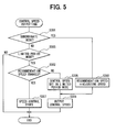
- FIG. 5 is a flow diagram of outputting the control speed
- FIGS. 6A and 6B illustrate a meter instrument that includes a liquid crystal display member of the recommendation speed display system
- FIG. 7 illustrates a display of the recommendation speed display system projected on a windshield glass.
- a vehicle control system that includes the recommendation speed display system will be described with reference to FIG. 1 .
- the vehicle control system is mounted in a vehicle and constructed of a recommendation speed processing unit 10 , an operating panel 21 , a display unit 22 , a laser radar 23 , a millimeter wave radar 23 ′, a road-to-vehicle communication unit 24 , a vehicle-to-vehicle communication unit 24 ′, a navigation system 25 , a camera 26 , a vehicle monitoring system 27 , a vehicle speed sensor 31 , a vehicle speed control value calculation section (hereinafter referred to as speed calculation section) 32 , a vehicle motion control section 33 , a power train 34 , a brake system 35 , etc.
- speed calculation section vehicle speed control value calculation section
- the operating panel 21 is provided with plural push buttons for inputting command signals that include the signal of a set speed.
- the operating panel may be provided with a voice recognition device instead of the push buttons.
- the display unit 22 is mounted in a speedometer, as shown in FIGS. 2A-2G
- the display unit 22 is constructed of a character display section disposed at a central portion of the speedometer and a speed indicating section disposed along the periphery of the speedometer.
- the character display section is constructed of a liquid crystal display member that displays a message provided by the recommendation speed processing unit 10 by red or blue characters.
- the speed indicating section is constructed of plural LED's disposed along the periphery of the speedometer so that red (R), blue (B) or green (G) spot light can be turned on at portions that correspond to the scales of the speedometer to indicate a maximum speed, a recommendation speed or a control speed according to a signal provided by the recommendation speed processing unit 10 .
- the display unit 22 may be mounted on a portion of a meter panel, as shown in FIGS. 6A and 6B .
- the display unit may be mounted in a head up display to display information on a portion of the windshield grass in front of the driver seat, as shown in FIG. 7 .
- the laser radar 23 is located at the front of the vehicle.
- the laser radar 23 includes a transmitting section that scans laser light having the directivity right and left and a receiving section that receives reflected light of the laser light.
- the laser radar 23 detects an object coming up ahead of the vehicle based on the scanned laser light and the reflected laser right, measures the distance between the vehicle and the object and sends its output signal to the recommendation speed processing unit 10 .
- the radar 23 ′ is also located at the front of the vehicle.
- the radar 23 ′ includes a transmitting section that emits radio wave and a receiving section that receives reflected wave of the radio wave.
- the radar 23 ′ detects an object coming up ahead of the vehicle based on the radio wave and the reflected wave of the radio wave, measures the distance and a relative speed between the vehicle and the object, and sends its output signal to the recommendation speed processing unit 10 .
- the road-to-vehicle communication unit 24 receives various kinds of information, such as information on the highway regulation from an on-road communication facility by means of short-distance wireless communication and sends the data to the recommendation speed processing unit 10 .
- the vehicle-to-vehicle communication unit 24 ′ receives data on the vehicle speed, vehicle location, vehicle conditions, braking, etc. from an on-vehicle communication device of a neighboring vehicle by means of short-distance wireless communication and sends the data to the recommendation speed processing unit 10 .
- the navigation system 25 outputs various kinds of information such as the speed limit, traffic jam, blockage of road due to construction or a traffic accident, school zone, residential area, own vehicle location, etc. to the recommendation speed processing unit 10 .
- the camera 26 periodically monitors the vehicle driver's face or countenance and outputs a monitored image to the recommendation speed processing unit 10 .
- the monitoring system 27 detects a trouble or an abnormality of the following systems or devices: ESC (electronic stability control) system, ABS (antilock brake control) system, a suspension control system, an electronic four-wheel-driving control system, an electronic differential gear control system, a catalyzer, tire's air pressure, etc.
- the monitoring system 27 also reports such a trouble or an abnormality to the recommendation speed processing unit 10 .
- the recommendation speed processing unit 10 provides a control speed based on a signal received from the operating panel 21 , sends a control speed signal to the speed calculation section 32 so as to control the vehicle speed within the control speed, as a set speed, and provide a recommendation speed that is optimum under circumstances on the display unit.
- the vehicle speed sensor 31 detects the vehicle speed (or running speed of the vehicle).
- the speed calculation section 32 calculates a control value to control the actual vehicle speed and sends the control value to the vehicle motion control section 33 .
- the vehicle motion control section 33 controls the power train 34 and the brake 35 based on the control value and the operation of the accelerator pedal and the brake pedal, thereby controlling the vehicle speed within the control speed.
- the recommendation speed processing unit 10 is mainly constructed of a microcomputer that includes CPU, ROM, RAM, I/O and bus lines. As shown in FIG. 1 , the recommendation speed processing unit 10 includes a neighboring circumstance recognition section 11 , a driver condition recognition section 12 , a vehicle condition recognition section 13 , a first recommendation speed calculation section 14 , a second recommendation speed calculation section 15 , a control speed calculation section 16 and a display data formation section 17 , which may be separated or joined to each other.
- the neighboring circumstance recognition section 11 recognizes neighboring circumstances based on the data received from the laser radar 23 , the road-to-vehicle communication unit 24 and the navigation system 25 and sends a circumstance recognition signal to the first recommendation speed calculation section 14 .
- the driver condition recognition section 12 recognizes the driver's face or countenance based on the monitored image received from the camera 26 and sends a driver condition recognition signal to the first recommendation speed calculation section 14 .
- the vehicle condition recognition section 13 recognizes a trouble or abnormality of the vehicle based on the data received from the vehicle monitoring system 27 and sends an abnormality recognition signal to the second recommendation speed calculation section 15 .
- the first recommendation speed calculation section 14 calculates plural candidates of recommendation speeds based on the data received from the neighboring circumstance recognition section 11 and driver condition recognition section 12 and outputs the lowest one of the candidates as the recommendation speed to the display data formation section 17 .
- the control speed calculation section 16 calculates a control speed based on the signal received from the operating panel 21 and sends a control speed signal to the display data formation section 17 and the speed calculation section 32 .
- the display data formation section 17 forms a display image based on a first recommendation speed signal received from the first recommendation speed calculation section 14 , a second recommendation speed signal received from the second recommendation speed calculation section 15 and a control speed signal received from the control speed calculation section 16 and sends a display image signal to the display unit 22 .
- the first recommendation speed calculation section 14 periodically (e.g. each 100 ms) calculates the first candidates of the recommendation speed based on the data received from the neighboring circumstance recognition section 11 and driver condition recognition section 12 , at step S 101 .
- whether there is any preceding vehicle running ahead of the own vehicle is examined based on the output signal of the laser radar 23 , and a candidate of the recommendation speed is set based on a preceding vehicle's speed if there is such a preceding vehicle. Otherwise, the recommendation speed is not set.
- the speed limit is set as a candidate of the recommendation speed. Otherwise, the recommendation speed is not set.
- the detected speed limit is set as a candidate of the recommendation speed. Otherwise, the recommendation speed is not set.
- a preset speed for the traffic jam is set as a candidate of the recommendation speed. Otherwise, the recommendation speed is not set.
- the sleepiness of the driver is examined based on the data signal received from the camera 26 . If it is determined that the driver is sleepy, a preset speed for the sleepy driver is set as a candidate of the recommendation speed. Incidentally, the sleepiness can be judged by the motion of the eyelids. The sleepiness can be also judged by driver's pulsation. In this case, the camera is replaced with a pulse sensor. Instead of sleepiness, driver condition may be examined.
- the lowest candidates of the recommendation speed is finally set as the first recommendation speed.
- the second recommendation speed is set based on the information about a trouble or an abnormality at S 102 .
- whether a trouble or an abnormality of the own vehicle takes place or not is examined based on the information received from the vehicle monitoring system 27 . If there is a trouble or an abnormality, a preset speed for the trouble or abnormality is set as the second recommendation speed. Otherwise, it is not set.
- a display recommendation speed is determined out of the first recommendation speed and the second recommendation speed at S 103 . If the first and second recommendation speeds are set, the lower one of the recommendation speeds is displayed as the display recommendation speed. If only one of the first and second recommendation is provided, the only one recommendation speed is displayed as the display recommendation speed. If none of the first and second recommendation speed is provided, a preset speed such as the legal speed limit is displayed as the display recommendation speed.
- a blue-colored message “TRAFFIC JAM AHEAD” is formed to be displayed by the display unit 22 with a blue colored display of the display recommendation speed (the first recommendation speed), as shown in FIG. 2D .
- a red-colored message “ESC FAILS” is formed to be displayed with a red-colored display of the display recommendation speed (the second recommendation speed), as shown in FIG. 2A .
- the red colored message and red colored display recommendation speed represents higher importance than the blue colored message and display recommendation speed.
- the display recommendation speed that is determined at S 103 , the information about reasons of the display recommendation speed and the control speed that is set at S 302 or S 305 are outputted to the display unit 22 , in which the display recommendation speed is displayed by a red or blue spot light and the control speed is displayed by a blue spot light. Then the display information outputting process is ended.
- a control speed setting process for automatically controlling the vehicle speed will be described with reference to FIG. 4 .
- the subordinate mode is a mode to control the vehicle speed based on a control speed that changes according to the display recommendation speed displayed by the display unit.
- the subordinate mode is started at S 203 , and the control speed setting process is ended thereafter. If the result of the examination at S 202 is NO, a limited period mode is started at S 204 and, thereafter, the control speed setting process is ended.
- the limited period mode is a mode to control the vehicle speed based on a set speed in a limited period until the display recommendation speed changes.
- a control speed outputting process for automatically controlling the vehicle speed will be described with reference to FIG. 5 .
- the recommendation speed display system determines a recommendation speed that is optimum for a specific circumstance and displays the display recommendation speed regardless of whether an actual vehicle speed is higher than the display recommendation speed or not. Therefore, a driver can always grasp the display recommendation speed while he is driving the vehicle, so that the driver will not feel irritated by a difference between the intention of the driver and the vehicle operation.
Abstract
Description
Claims (16)
Applications Claiming Priority (2)
| Application Number | Priority Date | Filing Date | Title |
|---|---|---|---|
| JP2006-131601 | 2006-05-10 | ||
| JP2006131601A JP4882499B2 (en) | 2006-05-10 | 2006-05-10 | Speed information providing apparatus and program |
Publications (2)
| Publication Number | Publication Date |
|---|---|
| US20070262883A1 US20070262883A1 (en) | 2007-11-15 |
| US7911361B2 true US7911361B2 (en) | 2011-03-22 |
Family
ID=38580227
Family Applications (1)
| Application Number | Title | Priority Date | Filing Date |
|---|---|---|---|
| US11/730,945 Expired - Fee Related US7911361B2 (en) | 2006-05-10 | 2007-04-05 | Vehicle recommendation speed display system |
Country Status (3)
| Country | Link |
|---|---|
| US (1) | US7911361B2 (en) |
| JP (1) | JP4882499B2 (en) |
| DE (1) | DE102007016882B4 (en) |
Cited By (6)
| Publication number | Priority date | Publication date | Assignee | Title |
|---|---|---|---|---|
| US20100217477A1 (en) * | 2007-10-30 | 2010-08-26 | Brody Engineering Ltd. | Speed deviation indicator |
| US20120253628A1 (en) * | 2011-03-29 | 2012-10-04 | Fuji Jukogyo Kabushiki Kaisha | Driving support apparatus for vehicle |
| US20130138319A1 (en) * | 2011-05-25 | 2013-05-30 | Audi Ag | Method for operating a longitudinally guiding driver assist system and motor vehicle |
| US20150243168A1 (en) * | 2012-10-31 | 2015-08-27 | Bayerische Motoren Werke Aktiengesellschaft | Vehicle Assistance Device |
| US9499114B2 (en) | 2013-02-27 | 2016-11-22 | Gentex Corporation | System and method for monitoring vehicle speed and driver notification |
| US20170096129A1 (en) * | 2015-10-06 | 2017-04-06 | Mando Corporation | Control apparatus for electronic parking brake system and control method thereof |
Families Citing this family (14)
| Publication number | Priority date | Publication date | Assignee | Title |
|---|---|---|---|---|
| JP2008265706A (en) * | 2007-04-25 | 2008-11-06 | Nissan Motor Co Ltd | Vehicle traveling control device and vehicle traveling control method |
| JP5478042B2 (en) * | 2008-09-03 | 2014-04-23 | トヨタ自動車株式会社 | Travel control device |
| US20100315218A1 (en) * | 2009-06-12 | 2010-12-16 | David Cades | Inclement Condition Speedometer |
| FR2966396B1 (en) * | 2010-10-21 | 2012-10-26 | Peugeot Citroen Automobiles Sa | DEVICE FOR INDICATING THE REGULATORY MAXIMUM SPEED ON A TACHOMETER OF A VEHICLE BASED ON PLUVIOMETRY |
| TW201226245A (en) * | 2010-12-31 | 2012-07-01 | Altek Corp | Vehicle apparatus control system and method thereof |
| WO2012166010A1 (en) * | 2011-06-01 | 2012-12-06 | Kolyunov Andrey Ivanovich | Recommended travel speed indicator device |
| FR2976866B1 (en) | 2011-06-27 | 2013-07-05 | Peugeot Citroen Automobiles Sa | METHOD FOR AIDING THE DRIVING OF A VEHICLE |
| US20150258995A1 (en) * | 2012-10-22 | 2015-09-17 | Takata AG | Method and Assistance System for Assisting a Driver of a Motor Vehicle as well as Measuring Method and Measuring System for Determining a Mental State of a Driver of a Motor Vehicle |
| US9566896B2 (en) * | 2014-08-15 | 2017-02-14 | Continental Automotive Systems, Inc. | Vehicle cluster with high speed warning indicator using position data |
| JP6274177B2 (en) * | 2015-10-19 | 2018-02-07 | トヨタ自動車株式会社 | Vehicle control system |
| KR102585219B1 (en) * | 2016-11-29 | 2023-10-05 | 삼성전자주식회사 | Device and method to control speed of vehicle |
| JP6481698B2 (en) * | 2017-02-17 | 2019-03-13 | マツダ株式会社 | Display device |
| US10358129B2 (en) * | 2017-06-06 | 2019-07-23 | Toyota Motor Engineering & Manufacturing North America, Inc. | Systems and methods for dynamic vehicle control according to traffic |
| JP6968005B2 (en) * | 2018-03-09 | 2021-11-17 | 川崎重工業株式会社 | Information transmission method for vehicles and information transmission system for motorcycles |
Citations (48)
| Publication number | Priority date | Publication date | Assignee | Title |
|---|---|---|---|---|
| US567531A (en) * | 1896-09-08 | Holder for electric lamps | ||
| US3596242A (en) * | 1969-01-14 | 1971-07-27 | Ross And White Co | Speed warning system |
| US3960410A (en) * | 1973-10-31 | 1976-06-01 | Ernst Leitz G.M.B.H. | System for achieving a maximum braking effect |
| US4101870A (en) * | 1976-01-21 | 1978-07-18 | Adolphe Ekman | Device for indicating speed levels for motor vehicles |
| DE3619824A1 (en) | 1986-06-12 | 1987-12-17 | Ernst D Prof Dr Ing Dickmanns | System for indicating the currently valid maximum speed, or the maximum speed which is safe for the environmental conditions, for road vehicles |
| US4874242A (en) * | 1985-07-04 | 1989-10-17 | Jaeger | Device for detection of extraneous substances through a wall and a system for aiding the driving of automobiles or airplanes |
| US4931767A (en) * | 1987-10-17 | 1990-06-05 | Daimler-Benz Ag | Device for visibility measurement for a motor vehicle |
| DE4325721A1 (en) | 1993-07-30 | 1995-02-02 | Bayerische Motoren Werke Ag | Display device |
| JPH09257507A (en) | 1996-03-18 | 1997-10-03 | Aqueous Res:Kk | Display device for vehicle |
| DE19620467A1 (en) | 1996-05-21 | 1997-11-27 | Bayerische Motoren Werke Ag | Optical indicator for vehicles with speed regulator |
| US5815072A (en) * | 1996-07-10 | 1998-09-29 | Toyoda Gosei Co., Ltd. | Vehicle display device |
| US5942979A (en) * | 1997-04-07 | 1999-08-24 | Luppino; Richard | On guard vehicle safety warning system |
| DE19901808A1 (en) | 1999-01-19 | 2000-07-20 | Volkswagen Ag | Display device for vehicle speed converts received data signal into suitable format for processor that displays maximum permitted speed on tachometer via display controller |
| US6188312B1 (en) * | 1999-03-01 | 2001-02-13 | Thomas Gotauco | Apparatus and method to stimulate a sleepy driver |
| US6278928B1 (en) * | 1996-04-12 | 2001-08-21 | Kabushikikaisha Equos Research | Transmission control device responsive to road information |
| JP2002025000A (en) | 2000-07-11 | 2002-01-25 | Mazda Motor Corp | Control device for vehicle |
| US6356833B2 (en) * | 1999-12-14 | 2002-03-12 | Hyundai Motor Company | Vehicle speed control system using wireless communications and method for controlling the same |
| JP2002163785A (en) | 2000-11-22 | 2002-06-07 | Mazda Motor Corp | Controller for vehicle |
| JP2002166749A (en) | 2000-12-01 | 2002-06-11 | Yazaki Corp | Optimum speed display device for vehicle |
| JP2002329300A (en) | 2001-04-27 | 2002-11-15 | Honda Motor Co Ltd | Travel safety device for vehicle |
| US20020170762A1 (en) * | 2001-05-21 | 2002-11-21 | Daneshmand Mohammad R. | Automobile speed limiter system |
| US6498976B1 (en) * | 2000-10-30 | 2002-12-24 | Freightliner Llc | Vehicle operator advisor system and method |
| US6728623B2 (en) * | 2000-02-23 | 2004-04-27 | Hitachi, Ltd. | Running control device for a vehicle |
| US6731925B2 (en) * | 2001-10-24 | 2004-05-04 | Mouhamad Ahmad Naboulsi | Safety control system for vehicles |
| US6737963B2 (en) * | 2001-03-30 | 2004-05-18 | Koninklijke Philips Electronics N.V. | Driver tailgating and following aid |
| JP2004142686A (en) | 2002-10-28 | 2004-05-20 | Hitachi Ltd | Running controller for automobile and running control system of automobile |
| JP2004210053A (en) | 2002-12-27 | 2004-07-29 | Nissan Motor Co Ltd | Traveling control device for vehicle |
| JP2004287856A (en) | 2003-03-20 | 2004-10-14 | Nec Saitama Ltd | Reporting device, vehicle drive supporting system, vehicle drive supporting method and vehicle drive supporting program |
| US20040209594A1 (en) * | 2002-11-04 | 2004-10-21 | Naboulsi Mouhamad A. | Safety control system for vehicles |
| JP2004322962A (en) | 2003-04-28 | 2004-11-18 | Honda Motor Co Ltd | Travel control unit for vehicle |
| US6825778B2 (en) * | 2002-10-21 | 2004-11-30 | International Road Dynamics Inc. | Variable speed limit system |
| JP2005121382A (en) * | 2003-10-14 | 2005-05-12 | Nissan Motor Co Ltd | Running state notify system |
| JP2005140084A (en) | 2003-11-10 | 2005-06-02 | Denso Corp | Vehicle control device |
| US20050131614A1 (en) * | 2003-12-12 | 2005-06-16 | Denso Corporation | Vehicle driving system and method |
| US20050150701A1 (en) * | 2002-03-09 | 2005-07-14 | Harald Michi | Cruise control system having a stop & go function |
| US6920234B1 (en) | 1999-05-08 | 2005-07-19 | Robert Bosch Gmbh | Method and device for monitoring the interior and surrounding area of a vehicle |
| US6927694B1 (en) | 2001-08-20 | 2005-08-09 | Research Foundation Of The University Of Central Florida | Algorithm for monitoring head/eye motion for driver alertness with one camera |
| JP2005227008A (en) | 2004-02-10 | 2005-08-25 | Nissan Motor Co Ltd | Cruise condition advice system |
| JP2005228137A (en) * | 2004-02-13 | 2005-08-25 | Nissan Motor Co Ltd | Travel state advice system |
| JP2005234758A (en) * | 2004-02-18 | 2005-09-02 | Nissan Motor Co Ltd | Travel situation advice system |
| JP2005234775A (en) | 2004-02-18 | 2005-09-02 | Nissan Motor Co Ltd | Travel situation advice system |
| US20060028330A1 (en) * | 2004-08-06 | 2006-02-09 | David Gallant | Heads-up speed display for vehicles |
| US20060095193A1 (en) * | 2004-10-29 | 2006-05-04 | Nissan Motor Co., Ltd. | Vehicle operation support apparatus |
| US20060235597A1 (en) * | 2005-03-03 | 2006-10-19 | Aisin Aw Co., Ltd. | Driving support method and device |
| US7202792B2 (en) * | 2002-11-11 | 2007-04-10 | Delphi Technologies, Inc. | Drowsiness detection system and method |
| US7222009B2 (en) * | 2003-09-18 | 2007-05-22 | Nissan Motor Co., Ltd. | Driving assist system for vehicle |
| US7333007B2 (en) * | 2004-03-11 | 2008-02-19 | Bayerische Motoren Werke Aktiengesellschaft | Process for the output of information in a vehicle |
| US7519471B2 (en) * | 2004-10-15 | 2009-04-14 | Aisin Aw Co., Ltd. | Driving support methods, apparatus, and programs |
Family Cites Families (5)
| Publication number | Priority date | Publication date | Assignee | Title |
|---|---|---|---|---|
| JPH10320700A (en) * | 1997-05-15 | 1998-12-04 | Toyota Motor Corp | Vehicle controller |
| JP3666338B2 (en) * | 2000-01-20 | 2005-06-29 | 日産自動車株式会社 | Vehicle travel control device |
| JP4742451B2 (en) * | 2000-07-11 | 2011-08-10 | トヨタ自動車株式会社 | Travel control device |
| JP5023407B2 (en) * | 2000-11-22 | 2012-09-12 | マツダ株式会社 | Vehicle control device |
| JP2002362183A (en) * | 2001-06-11 | 2002-12-18 | Honda Motor Co Ltd | Traveling safety device for vehicle |
-
2006
- 2006-05-10 JP JP2006131601A patent/JP4882499B2/en not_active Expired - Fee Related
-
2007
- 2007-04-05 US US11/730,945 patent/US7911361B2/en not_active Expired - Fee Related
- 2007-04-10 DE DE102007016882A patent/DE102007016882B4/en not_active Expired - Fee Related
Patent Citations (50)
| Publication number | Priority date | Publication date | Assignee | Title |
|---|---|---|---|---|
| US567531A (en) * | 1896-09-08 | Holder for electric lamps | ||
| US3596242A (en) * | 1969-01-14 | 1971-07-27 | Ross And White Co | Speed warning system |
| US3960410A (en) * | 1973-10-31 | 1976-06-01 | Ernst Leitz G.M.B.H. | System for achieving a maximum braking effect |
| US4101870A (en) * | 1976-01-21 | 1978-07-18 | Adolphe Ekman | Device for indicating speed levels for motor vehicles |
| US4874242A (en) * | 1985-07-04 | 1989-10-17 | Jaeger | Device for detection of extraneous substances through a wall and a system for aiding the driving of automobiles or airplanes |
| DE3619824A1 (en) | 1986-06-12 | 1987-12-17 | Ernst D Prof Dr Ing Dickmanns | System for indicating the currently valid maximum speed, or the maximum speed which is safe for the environmental conditions, for road vehicles |
| US4931767A (en) * | 1987-10-17 | 1990-06-05 | Daimler-Benz Ag | Device for visibility measurement for a motor vehicle |
| DE4325721A1 (en) | 1993-07-30 | 1995-02-02 | Bayerische Motoren Werke Ag | Display device |
| JPH09257507A (en) | 1996-03-18 | 1997-10-03 | Aqueous Res:Kk | Display device for vehicle |
| US6278928B1 (en) * | 1996-04-12 | 2001-08-21 | Kabushikikaisha Equos Research | Transmission control device responsive to road information |
| DE19620467A1 (en) | 1996-05-21 | 1997-11-27 | Bayerische Motoren Werke Ag | Optical indicator for vehicles with speed regulator |
| US5815072A (en) * | 1996-07-10 | 1998-09-29 | Toyoda Gosei Co., Ltd. | Vehicle display device |
| US5942979A (en) * | 1997-04-07 | 1999-08-24 | Luppino; Richard | On guard vehicle safety warning system |
| DE19901808A1 (en) | 1999-01-19 | 2000-07-20 | Volkswagen Ag | Display device for vehicle speed converts received data signal into suitable format for processor that displays maximum permitted speed on tachometer via display controller |
| US6188312B1 (en) * | 1999-03-01 | 2001-02-13 | Thomas Gotauco | Apparatus and method to stimulate a sleepy driver |
| US6920234B1 (en) | 1999-05-08 | 2005-07-19 | Robert Bosch Gmbh | Method and device for monitoring the interior and surrounding area of a vehicle |
| US6356833B2 (en) * | 1999-12-14 | 2002-03-12 | Hyundai Motor Company | Vehicle speed control system using wireless communications and method for controlling the same |
| US6728623B2 (en) * | 2000-02-23 | 2004-04-27 | Hitachi, Ltd. | Running control device for a vehicle |
| JP2002025000A (en) | 2000-07-11 | 2002-01-25 | Mazda Motor Corp | Control device for vehicle |
| US6498976B1 (en) * | 2000-10-30 | 2002-12-24 | Freightliner Llc | Vehicle operator advisor system and method |
| JP2002163785A (en) | 2000-11-22 | 2002-06-07 | Mazda Motor Corp | Controller for vehicle |
| JP2002166749A (en) | 2000-12-01 | 2002-06-11 | Yazaki Corp | Optimum speed display device for vehicle |
| US6737963B2 (en) * | 2001-03-30 | 2004-05-18 | Koninklijke Philips Electronics N.V. | Driver tailgating and following aid |
| JP2002329300A (en) | 2001-04-27 | 2002-11-15 | Honda Motor Co Ltd | Travel safety device for vehicle |
| US20020170762A1 (en) * | 2001-05-21 | 2002-11-21 | Daneshmand Mohammad R. | Automobile speed limiter system |
| US6927694B1 (en) | 2001-08-20 | 2005-08-09 | Research Foundation Of The University Of Central Florida | Algorithm for monitoring head/eye motion for driver alertness with one camera |
| US6731925B2 (en) * | 2001-10-24 | 2004-05-04 | Mouhamad Ahmad Naboulsi | Safety control system for vehicles |
| US20050150701A1 (en) * | 2002-03-09 | 2005-07-14 | Harald Michi | Cruise control system having a stop & go function |
| US6825778B2 (en) * | 2002-10-21 | 2004-11-30 | International Road Dynamics Inc. | Variable speed limit system |
| JP2004142686A (en) | 2002-10-28 | 2004-05-20 | Hitachi Ltd | Running controller for automobile and running control system of automobile |
| US20040209594A1 (en) * | 2002-11-04 | 2004-10-21 | Naboulsi Mouhamad A. | Safety control system for vehicles |
| US7202792B2 (en) * | 2002-11-11 | 2007-04-10 | Delphi Technologies, Inc. | Drowsiness detection system and method |
| JP2004210053A (en) | 2002-12-27 | 2004-07-29 | Nissan Motor Co Ltd | Traveling control device for vehicle |
| JP2004287856A (en) | 2003-03-20 | 2004-10-14 | Nec Saitama Ltd | Reporting device, vehicle drive supporting system, vehicle drive supporting method and vehicle drive supporting program |
| JP2004322962A (en) | 2003-04-28 | 2004-11-18 | Honda Motor Co Ltd | Travel control unit for vehicle |
| US7222009B2 (en) * | 2003-09-18 | 2007-05-22 | Nissan Motor Co., Ltd. | Driving assist system for vehicle |
| JP2005121382A (en) * | 2003-10-14 | 2005-05-12 | Nissan Motor Co Ltd | Running state notify system |
| JP2005140084A (en) | 2003-11-10 | 2005-06-02 | Denso Corp | Vehicle control device |
| US20050131614A1 (en) * | 2003-12-12 | 2005-06-16 | Denso Corporation | Vehicle driving system and method |
| JP2005227008A (en) | 2004-02-10 | 2005-08-25 | Nissan Motor Co Ltd | Cruise condition advice system |
| JP2005228137A (en) * | 2004-02-13 | 2005-08-25 | Nissan Motor Co Ltd | Travel state advice system |
| JP2005234758A (en) * | 2004-02-18 | 2005-09-02 | Nissan Motor Co Ltd | Travel situation advice system |
| JP2005234775A (en) | 2004-02-18 | 2005-09-02 | Nissan Motor Co Ltd | Travel situation advice system |
| US7333007B2 (en) * | 2004-03-11 | 2008-02-19 | Bayerische Motoren Werke Aktiengesellschaft | Process for the output of information in a vehicle |
| US20060028330A1 (en) * | 2004-08-06 | 2006-02-09 | David Gallant | Heads-up speed display for vehicles |
| US7327239B2 (en) * | 2004-08-06 | 2008-02-05 | Invision Systems, Llc | Heads-up speed display for vehicles |
| US20080157952A1 (en) * | 2004-08-06 | 2008-07-03 | David Gallant | Heads-up speed display for vehicles |
| US7519471B2 (en) * | 2004-10-15 | 2009-04-14 | Aisin Aw Co., Ltd. | Driving support methods, apparatus, and programs |
| US20060095193A1 (en) * | 2004-10-29 | 2006-05-04 | Nissan Motor Co., Ltd. | Vehicle operation support apparatus |
| US20060235597A1 (en) * | 2005-03-03 | 2006-10-19 | Aisin Aw Co., Ltd. | Driving support method and device |
Non-Patent Citations (2)
| Title |
|---|
| Office Action dated Feb. 2, 2009 in corresponding German patent application No. 10 2007 016 882.0-31 (and English translation). |
| Office Action dated Oct. 26, 2010 in corresponding Japanese patent application No. 2006-131601 (and English translation). |
Cited By (10)
| Publication number | Priority date | Publication date | Assignee | Title |
|---|---|---|---|---|
| US20100217477A1 (en) * | 2007-10-30 | 2010-08-26 | Brody Engineering Ltd. | Speed deviation indicator |
| US20120253628A1 (en) * | 2011-03-29 | 2012-10-04 | Fuji Jukogyo Kabushiki Kaisha | Driving support apparatus for vehicle |
| US8983750B2 (en) * | 2011-03-29 | 2015-03-17 | Fuji Jukogyo Kabushiki Kaisha | Driving support apparatus for vehicle |
| US20130138319A1 (en) * | 2011-05-25 | 2013-05-30 | Audi Ag | Method for operating a longitudinally guiding driver assist system and motor vehicle |
| US9043115B2 (en) * | 2011-05-25 | 2015-05-26 | Audi Ag | Method for operating a longitudinally guiding driver assist system and motor vehicle |
| US20150243168A1 (en) * | 2012-10-31 | 2015-08-27 | Bayerische Motoren Werke Aktiengesellschaft | Vehicle Assistance Device |
| US10424201B2 (en) | 2012-10-31 | 2019-09-24 | Bayerische Motoren Werke Aktiengesellschaft | Vehicle assistance device |
| US9499114B2 (en) | 2013-02-27 | 2016-11-22 | Gentex Corporation | System and method for monitoring vehicle speed and driver notification |
| US20170096129A1 (en) * | 2015-10-06 | 2017-04-06 | Mando Corporation | Control apparatus for electronic parking brake system and control method thereof |
| US10682995B2 (en) * | 2015-10-06 | 2020-06-16 | Mando Corporation | Control apparatus for electronic parking brake system and control method thereof |
Also Published As
| Publication number | Publication date |
|---|---|
| US20070262883A1 (en) | 2007-11-15 |
| DE102007016882A1 (en) | 2007-11-15 |
| JP4882499B2 (en) | 2012-02-22 |
| DE102007016882B4 (en) | 2011-02-24 |
| JP2007304791A (en) | 2007-11-22 |
Similar Documents
| Publication | Publication Date | Title |
|---|---|---|
| US7911361B2 (en) | Vehicle recommendation speed display system | |
| US11312378B2 (en) | System and method for vehicle control using vehicular communication | |
| US10625742B2 (en) | System and method for vehicle control in tailgating situations | |
| US10737667B2 (en) | System and method for vehicle control in tailgating situations | |
| US10613531B2 (en) | Vehicle drive assistance system | |
| EP2355994B1 (en) | Integrated visual display system | |
| US8878693B2 (en) | Driver assistance device and method of controlling the same | |
| US7378986B2 (en) | Device and method for radio-based danger warning | |
| EP2748805B1 (en) | Drive support device and drive support method | |
| US8179281B2 (en) | Method and apparatus for identifying concealed objects in road traffic | |
| US8103449B2 (en) | Configurable vehicular time to stop warning system | |
| US7382274B1 (en) | Vehicle interaction communication system | |
| JP6317315B2 (en) | Sign information display device and method | |
| US8405523B2 (en) | Drive assist device and method | |
| US9892641B2 (en) | Regulatory information notifying device and method | |
| JP5459278B2 (en) | Driving assistance device | |
| CN102066181A (en) | Vehicle driver messaging system and method | |
| US20170178591A1 (en) | Sign display apparatus and method for vehicle | |
| US20220319317A1 (en) | Driving assist apparatus | |
| EP2196961A1 (en) | A driver information system for a vehicle, for providing input to a driver regarding the traffic environment external of said vehicle | |
| US20200294432A1 (en) | Advertisement display device, vehicle, and advertisement display method | |
| JP2009087249A (en) | On-vehicle traffic congestion warning device | |
| US20040267453A1 (en) | Speed-monitoring radar-activated brake light | |
| CN113034934A (en) | Communication control system and method for vehicle | |
| TWI798082B (en) | Driving behavior warning system and method |
Legal Events
| Date | Code | Title | Description |
|---|---|---|---|
| AS | Assignment |
Owner name: DENSO CORPORATION, JAPAN Free format text: ASSIGNMENT OF ASSIGNORS INTEREST;ASSIGNOR:KUMABE, HAJIME;REEL/FRAME:019200/0302 Effective date: 20070326 |
|
| STCF | Information on status: patent grant |
Free format text: PATENTED CASE |
|
| FEPP | Fee payment procedure |
Free format text: PAYOR NUMBER ASSIGNED (ORIGINAL EVENT CODE: ASPN); ENTITY STATUS OF PATENT OWNER: LARGE ENTITY |
|
| FEPP | Fee payment procedure |
Free format text: PAYOR NUMBER ASSIGNED (ORIGINAL EVENT CODE: ASPN); ENTITY STATUS OF PATENT OWNER: LARGE ENTITY Free format text: PAYER NUMBER DE-ASSIGNED (ORIGINAL EVENT CODE: RMPN); ENTITY STATUS OF PATENT OWNER: LARGE ENTITY |
|
| FPAY | Fee payment |
Year of fee payment: 4 |
|
| MAFP | Maintenance fee payment |
Free format text: PAYMENT OF MAINTENANCE FEE, 8TH YEAR, LARGE ENTITY (ORIGINAL EVENT CODE: M1552); ENTITY STATUS OF PATENT OWNER: LARGE ENTITY Year of fee payment: 8 |
|
| FEPP | Fee payment procedure |
Free format text: MAINTENANCE FEE REMINDER MAILED (ORIGINAL EVENT CODE: REM.); ENTITY STATUS OF PATENT OWNER: LARGE ENTITY |
|
| LAPS | Lapse for failure to pay maintenance fees |
Free format text: PATENT EXPIRED FOR FAILURE TO PAY MAINTENANCE FEES (ORIGINAL EVENT CODE: EXP.); ENTITY STATUS OF PATENT OWNER: LARGE ENTITY |
|
| STCH | Information on status: patent discontinuation |
Free format text: PATENT EXPIRED DUE TO NONPAYMENT OF MAINTENANCE FEES UNDER 37 CFR 1.362 |
|
| FP | Lapsed due to failure to pay maintenance fee |
Effective date: 20230322 |