US7856421B2 - Maintaining memory checkpoints across a cluster of computing nodes - Google Patents
Maintaining memory checkpoints across a cluster of computing nodes Download PDFInfo
- Publication number
- US7856421B2 US7856421B2 US11/750,664 US75066407A US7856421B2 US 7856421 B2 US7856421 B2 US 7856421B2 US 75066407 A US75066407 A US 75066407A US 7856421 B2 US7856421 B2 US 7856421B2
- Authority
- US
- United States
- Prior art keywords
- memory
- node
- replica
- response
- primary portion
- Prior art date
- Legal status (The legal status is an assumption and is not a legal conclusion. Google has not performed a legal analysis and makes no representation as to the accuracy of the status listed.)
- Active, expires
Links
Images


Classifications
-
- G—PHYSICS
- G06—COMPUTING; CALCULATING OR COUNTING
- G06F—ELECTRIC DIGITAL DATA PROCESSING
- G06F11/00—Error detection; Error correction; Monitoring
- G06F11/07—Responding to the occurrence of a fault, e.g. fault tolerance
- G06F11/16—Error detection or correction of the data by redundancy in hardware
- G06F11/1666—Error detection or correction of the data by redundancy in hardware where the redundant component is memory or memory area
-
- G—PHYSICS
- G06—COMPUTING; CALCULATING OR COUNTING
- G06F—ELECTRIC DIGITAL DATA PROCESSING
- G06F11/00—Error detection; Error correction; Monitoring
- G06F11/07—Responding to the occurrence of a fault, e.g. fault tolerance
- G06F11/14—Error detection or correction of the data by redundancy in operation
- G06F11/1402—Saving, restoring, recovering or retrying
- G06F11/1405—Saving, restoring, recovering or retrying at machine instruction level
- G06F11/141—Saving, restoring, recovering or retrying at machine instruction level for bus or memory accesses
-
- G—PHYSICS
- G06—COMPUTING; CALCULATING OR COUNTING
- G06F—ELECTRIC DIGITAL DATA PROCESSING
- G06F11/00—Error detection; Error correction; Monitoring
- G06F11/07—Responding to the occurrence of a fault, e.g. fault tolerance
- G06F11/14—Error detection or correction of the data by redundancy in operation
- G06F11/1479—Generic software techniques for error detection or fault masking
- G06F11/1482—Generic software techniques for error detection or fault masking by means of middleware or OS functionality
-
- G—PHYSICS
- G06—COMPUTING; CALCULATING OR COUNTING
- G06F—ELECTRIC DIGITAL DATA PROCESSING
- G06F11/00—Error detection; Error correction; Monitoring
- G06F11/07—Responding to the occurrence of a fault, e.g. fault tolerance
- G06F11/16—Error detection or correction of the data by redundancy in hardware
- G06F11/1658—Data re-synchronization of a redundant component, or initial sync of replacement, additional or spare unit
-
- G—PHYSICS
- G06—COMPUTING; CALCULATING OR COUNTING
- G06F—ELECTRIC DIGITAL DATA PROCESSING
- G06F11/00—Error detection; Error correction; Monitoring
- G06F11/07—Responding to the occurrence of a fault, e.g. fault tolerance
- G06F11/16—Error detection or correction of the data by redundancy in hardware
- G06F11/20—Error detection or correction of the data by redundancy in hardware using active fault-masking, e.g. by switching out faulty elements or by switching in spare elements
- G06F11/2097—Error detection or correction of the data by redundancy in hardware using active fault-masking, e.g. by switching out faulty elements or by switching in spare elements maintaining the standby controller/processing unit updated
-
- G—PHYSICS
- G06—COMPUTING; CALCULATING OR COUNTING
- G06F—ELECTRIC DIGITAL DATA PROCESSING
- G06F11/00—Error detection; Error correction; Monitoring
- G06F11/07—Responding to the occurrence of a fault, e.g. fault tolerance
- G06F11/16—Error detection or correction of the data by redundancy in hardware
- G06F11/20—Error detection or correction of the data by redundancy in hardware using active fault-masking, e.g. by switching out faulty elements or by switching in spare elements
- G06F11/202—Error detection or correction of the data by redundancy in hardware using active fault-masking, e.g. by switching out faulty elements or by switching in spare elements where processing functionality is redundant
- G06F11/2043—Error detection or correction of the data by redundancy in hardware using active fault-masking, e.g. by switching out faulty elements or by switching in spare elements where processing functionality is redundant where the redundant components share a common memory address space
-
- G—PHYSICS
- G06—COMPUTING; CALCULATING OR COUNTING
- G06F—ELECTRIC DIGITAL DATA PROCESSING
- G06F12/00—Accessing, addressing or allocating within memory systems or architectures
- G06F12/02—Addressing or allocation; Relocation
- G06F12/08—Addressing or allocation; Relocation in hierarchically structured memory systems, e.g. virtual memory systems
- G06F12/0802—Addressing of a memory level in which the access to the desired data or data block requires associative addressing means, e.g. caches
- G06F12/0804—Addressing of a memory level in which the access to the desired data or data block requires associative addressing means, e.g. caches with main memory updating
Definitions
- This invention relates to computing network systems, and more particularly, to increasing the reliability and availability of a network system.
- High performance computing is often obtained by using high-end servers.
- clusters of multi-processor nodes may be coupled via a network to provide high performance computing.
- a cluster of nodes may have a lower financial cost of a high-end server.
- clusters of multi-processor nodes may lack the availability of high-end server based systems. Consequently, one method to increase the availability of a cluster of multi-processor nodes is memory replication.
- Memory replication generally includes maintaining one or more copies of a memory state in the cluster of nodes.
- One embodiment of the memory state may be the data content of memory and the processor architectural state content during the execution of an application.
- the memory state may need to be periodically updated in each copy in order to synchronize the copies with one another and with the original copy. If an executing application experiences a fault, the application can be restarted on another processor in another node and the memory state is recovered from the copy of memory state in this particular node.
- One method of maintaining memory replication for higher availability is by use of software techniques. However, software techniques involve significant overhead and thus, incorporate a performance penalty and scalability limits. Accordingly, efficient methods and mechanisms for managing clusters of computing nodes are desired.
- the nodes in a computing system are coupled to via a network.
- the nodes may include one or more processors, memory, and a “wiretap” unit (WT Unit), which may be an application specific integrated circuit (Unit).
- the WT Unit and the memory included in the node are coupled to the processor(s).
- the WT Unit is configured to monitor memory accesses of the processors.
- the nodes are configured to create copies of the memory state of an application, periodically synchronize the copies at checkpoints, and maintain a list of changes to the memory state between checkpoints.
- clusters are configured to restore the memory state of the copies to the state of the last successful checkpoint. Still further, contemplated are embodiments wherein the clusters are configured to restart the application on another processor included in one of the nodes with a restored copy of the memory state.
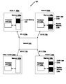
- FIG. 1 is a block diagram of a system containing a network and a cluster of nodes.
- FIG. 2 is a block diagram illustrating one embodiment of a node comprising a processor unit and memory in a network.
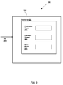
- FIG. 3 is a block diagram illustrating one embodiment of a device configured to maintain location information used for memory replication.
- FIG. 4A-4B is a block diagram illustrating one embodiment of a directory structure holding pointers to define regions of memory for memory replication.
- FIG. 5A-5B is a block diagram of a directory structure for mapping a Hardware Thread ID to a Replication Space ID.
- FIG. 6A-6B is a block diagram of a directory structure for storing information of dirty cache lines in a node.
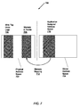
- FIG. 7 is a block diagram illustrating one embodiment of memory mapping between address space and physical memory.
- FIG. 8 is a flow diagram of one embodiment of a method for setup of memory replication.
- FIG. 9 is a flow diagram of one embodiment of a method for updating copies of memory used for an application and for updating a log of memory changes.
- FIG. 10 is a flow diagram of one embodiment of a method for synchronizing the memory used for an application and its copies.
- FIG. 11 is a flow diagram of one embodiment of a method for recovery of an application executed on a multi-processor network that experiences a fault.
- a system 100 that includes a cluster of multi-processor nodes 102 a - 102 d coupled to a network 104 through I/O interfaces 110 a - 110 d .
- network 104 may include remote direct memory access (RDMA) hardware and/or software.
- nodes 102 a - 102 d include a processor unit 106 and memory 108 .
- Processor unit 106 may comprise one or more processors.
- Physical memory of system 100 includes memory 108 a - 108 d of all the nodes.
- the system 100 includes operations, which are described in greater detail below, in order to maintain reliability and availability.
- the node that includes a processor where an application execution begins is referred to as the local node and its contents include the local processor unit and local memory.
- the one or more nodes that include a copy of the region of local memory used for the application execution are referred to as the replica nodes.
- the replica node includes the replica processor unit and replica memory.
- Node 200 includes a processor unit 202 that comprises one or more processors 204 a - 204 d , memory 210 , and a network I/O interface 208 .
- Processors 204 a - 204 d are coupled to a wiretap unit (WT Unit) 206 .
- WT Unit 206 comprises application specific integrated circuitry. The wiretap portion of the name is described below.
- Processors 204 a - 204 d and WT Unit 206 are coupled to the network I/O interface 208 , which may incorporate RDMA hardware and/or software.
- processors 204 a - 204 d are coupled to memory 210 within the node through Memory Buses 216 a - 216 d .
- Each processor 204 a - 204 d may be coupled to its own DRAM, which may be contained in memory 210 in the node.
- Memory 210 may comprise primary memory for processors 204 a - 204 d and secondary memory of any hard disk drives.
- Memory 210 may be configured to include a region of memory for the execution of an application, such as Local Memory 212 .
- memory 210 may include multiple regions of memory, such as Other Local Memory 214 a - 214 b , for the simultaneous execution of multiple applications.
- each processor 204 a - 204 d in order for each processor 204 a - 204 d to access memory, such as its respective primary memory (e.g., DRAM), each processor 204 a - 204 d must go through WT Unit 206 . Therefore, for example, write-back of a dirty cache line in a processor 204 a - 204 d to memory 210 in the node is monitored by WT Unit 206 . Because WT Unit 206 “taps” the interface between a processor 204 a - 204 d and memory 210 in the node, it is referred to as a wiretap unit (WT Unit).
- WT Unit 206 “taps” the interface between a processor 204 a - 204 d and memory 210 in the node, it is referred to as a wiretap unit (WT Unit).
- WT Unit 206 may make a duplicate, or replica, of the cache line and, through the network I/O interface 208 , send the replica to other nodes. Further discussion of this topic is given below. WT Unit 206 is further configured to access the DRAM of any processor 204 a - 204 d . WT Unit 206 may be configured to interface with other nodes, and thus, access the WT ASIC of other nodes.
- FIG. 3 illustrates one embodiment of a wiretap unit (WT Unit) 300 .
- WT Unit 302 may include an interface, I/O 312 , which allows WT Unit 302 to interface with one or more processors, memory, a network, and otherwise.
- the interface 312 may be configured to include hyper-transport links in the case that AMD OpteronTM processors are used in the nodes.
- each WT Unit 302 may include directories 304 of locations of information related to the operations of system 100 .
- Replication Space Directory 306 may include an array of entries. Each entry in directory 306 may correspond to information that needs to be maintained during the execution of an application. Such information may include pointers to the start and end of a region of physical memory dedicated to holding all the data.
- the setup of this region of memory will be described in greater detail below.
- the data within this region may include the locations of the original and copies of memory used during the execution of the application, the nodes of the original and copies, a pointer to the head of the Write Flush Directory 310 , and pointers to the start, end, and current entry of logs used to track operations performed on the memory state in order to possibly later restore the memory state to a predetermined state.
- Hardware Thread Directory 308 may be configured to include a map between hardware thread ID's that are transmitted in hyper-transport transactions and a replication space ID to correspond to which allocated space the application will execute.
- Write Flush Directory 310 may include a list of cache lines that have been written to for each transaction in progress. When a transaction completes, its corresponding list of cache writes is traversed and each cache line is flushed, or written-back to memory. The entries of this directory may contain a cache ID, the tag of the cache line, and state information.
- FIG. 4A illustrates one embodiment of a Replication Space Directory 400 .
- directory 400 may be comprised of an array of entries such as Directory Entry 402 .
- the array may be indexed by Replication Space ID 404 , which may be provided by a counter in WT Unit shown in FIG. 3 .
- Replication Space ID 404 may be provided by a counter in WT Unit shown in FIG. 3 .
- the output of the counter in WT Unit provides an index, Replication Space ID 404 , to determine which replication space may be used for the execution of the application.
- the space is allocated by the operating system prior to any applications running with memory replication.
- Directory Entry 402 may contain information to be maintained during the execution of an application. Further details of Directory Entry 402 are provided here.
- Directory Entry 402 there is shown one embodiment of Directory Entry 402 .
- pointers Phys Mem Region Start 406 and Phys Mem Region End 408 , to the start and end of the region of physical memory which holds the original and copies of data used during the execution of the application and the original and copies of logs of operations performed on original and copies of the memory state.
- Head of Write Flush List 410 used to locate the list of dirty cache lines that need to be written-back to memory during a checkpoint operation, a recovery operation, or a completion of the execution of the application.
- the field, No. of Copies 412 holds the value of the number of copies to be used during execution.
- This value relates to the number of copies to maintain of the data used during the execution of the application and the logs of the operations performed on the data during application execution.
- the third field, Undo Log Curr. Entry 418 a is a pointer to the current entry of the list of operations.
- the data on which the list of operations is performed lies in the region of memory set by the pointers, Node Mem Start 420 a and Node Mem End 422 a.
- FIG. 5A one embodiment of a Hardware Thread Directory 500 is illustrated.
- directory 500 may be configured to include a map between hardware thread ID's that are transmitted in hyper-transport transactions and a replication space ID to correspond to which allocated space the application will execute.
- a Hardware Thread ID 504 is used to index directory 500 to obtain an entry 502 .
- FIG. 5 B illustrates one embodiment of a directory entry 502 that may include a replication space ID 506 that specifies the allocated space for the local and copy regions of memory to be used during application execution.
- FIG. 6A illustrates one embodiment of a Write Flush Directory 600 .
- directory 600 is located by a Head Pointer 604 .
- This pointer is located in the Replication Space Directory in FIG. 3 .
- the list of entries, such as Directory Entry 602 is traversed, and dirty cache lines are written-back to memory.
- the first field, Cache ID 606 may be the location of the cache containing the dirty line.
- Valid 608 which is the state information of the dirty cache line and it may be valid or invalid.
- the tag of the address of the dirty line follows with field Tag 610 .
- Next 612 is a pointer to the next write flush entry for this application.
- FIG. 7 illustrates one embodiment of memory mapping 700 .
- Mapping 700 may occur between global address space 704 , or the virtual address space for system 100 , and physical address space 702 of system 100 .
- the operating system moves data between physical locations to improve performance or ensure reliability.
- the operating system creates a single virtual memory space.
- an application may only access addresses in space 704 that are set by WT Unit such as Application Assigned Address Space 710 .
- WT Unit such as Application Assigned Address Space 710 .
- These virtual addresses are mapped to the physical addresses Memory in Nodes 708 through Memory Mapping 712 .
- Addresses 708 are the addresses of the DRAM of the processors in the node running the application.
- Memory Mapping 712 may be implemented with a combination of a translation lookaside table (TLB) and a page table.
- TLB translation lookaside table
- Wire Tap Undo Logs 706 are stored in Physical Address Space 702 .
- Wire Tap Undo Logs 706 may be used to store operations performed on memory 708 during the execution of an application between checkpoints. Later, if necessary, the memory state of the last successful checkpoint may be restored by traversing the operations in Wire Tap Undo Logs 706 .
- the locations of both Wire Tap Undo Logs 706 and Memory in Nodes 708 are known to the WT Unit of the node in the Replication Space Directory in FIG. 4A-4B .
- WT Unit is configured to interface with the WT Unit of other nodes, and thus, access the memory and processors of other nodes.
- an application running on processor 0 of Node 0 may need to modify a line with an address in global address space that corresponds to a line in physical memory of Node 2 such as the DRAM of processor 3 of Node 2 .
- the WT Unit in all nodes contain access to this mapping.
- WT Unit 0 may interface with WT Unit 2 in order to allow the application running on processor 0 of Node 0 to temporarily run on processor 3 of Node 2 .
- a setup operation for system 100 may be performed.
- space in physical memory may be allocated as shown in FIG. 7 .
- Physical memory includes the memory in all nodes in FIG. 1 , which may be comprised of memory for the processors in the processor units 106 a - 106 d and any disk drives.
- the allocated space for the execution of the application in physical memory may be configured to store local memory, for example 112 in FIG. 1 , and copies of local memory, or replica memory, for example, 116 b - 116 c in FIG. 1 .
- the allocated space may also be configured to store undo logs such as 114 b - 114 c in FIG. 1 . A description of undo logs is given below. Software is required to handle the case when sufficient memory is not available.
- FIG. 8 there is shown a flow diagram illustrating one embodiment of a method for setup of memory replication on system 100 .
- the steps in this embodiment are shown in sequential order. However, some steps may occur in a different order than shown, some steps may be performed concurrently, some steps may be combined with other steps, and some steps may be absent in another embodiment.
- the operating system (O.S.) monitors the nodes in system 100 in block 802 .
- a processor i.e. processor 204 a - 204 d of FIG. 2
- the node of this processor will be denoted as the local node.
- the one or more nodes chosen to hold the copy, or replica, of the local memory will be denoted as the replica node(s). If a request is not made, the O.S. continues to monitor the nodes in system 100 . If a processor does have an application to execute and the processor requests memory replication, then steps are taken to find allocated space in system 100 for execution of the application.
- a local processor may program the local WT Unit to perform setup.
- a Hardware Thread ID may be used to index the Hardware Thread Directory in FIG. 3 . This indexing may lead to obtaining a Replication Space ID as shown in FIG. 5A-5B .
- Another alternative to obtaining a Replication Space ID is to use a counter for the Hardware Thread ID. Such a counter may be located in the WT Unit. Indexing of a directory as shown in FIG. 5A-5B would continue.
- a valid Replication Space ID is not found, meaning the value may be out of a predetermined range or a status bit may be stored with the ID value, then there is no sufficient memory in physical memory for the application execution. This is shown in decision block 806 . In this case, the O.S. must handle the situation and allow memory to become available as shown in block 516 . Perhaps the O.S. simply waits for other applications to finish and when it detects a valid Replication Space ID is available, its highest priority at that time is to allow the current application to obtain it.
- block 808 shows the O.S. has regions of memory allocated for the execution of the application.
- the node that includes a processor where an application execution begins is referred to as the local node and its contents include the local processor unit and local memory.
- the one or more nodes that include a copy of the region of local memory used for the application execution are referred to as the replica nodes.
- a replica node includes a replica processor unit and a replica memory. The purpose of the replica nodes is to maintain copies of the local memory during application execution as shown in FIG. 1 .
- the replica nodes may include regions of memory to store undo logs. The undo logs may include a list of operations performed on the local memory. Should a fault, hardware or software, occur, the replica nodes may use the undo logs to restore the replica memory to a predetermined state. Then one of the replica nodes is chosen to restart the application and become the new local node.
- FIG. 4A-4B illustrates the Replication Space ID indexes the Replication Space Directory located in the WT Unit shown in FIG. 3 .
- each entry 402 includes pointers that define the regions of memory for local memory, replica memories, and undo logs. These regions are shown in FIG. 1 in 112 , 114 b - 114 c , and 116 b - 116 c.
- the O.S. ensures the application accesses a virtual memory range 710 determined by the WT Unit.
- the physical addresses 708 are already determined by WT Unit 206 and the Replication Space Directory entry 402 .
- a combination of a translation lookaside buffer and a page table may be used to perform the memory mapping 712 . All WT Unit's of all nodes include this mapping or have access to this mapping.
- the local processor of the local node informs the local WT Unit 206 and the replica WT Unit's that setup has begun. In FIG. 1 , this may be performed by using the interfaces 110 a - 110 d and network 104 .
- the local WT Unit may need to wait for an acknowledgment signal from all replica nodes after informing the replica nodes of the start of setup. If all acknowledgment signals do not arrive in a predetermined time, the O.S. may be signaled to handle the current wait state and/or have setup begun again. Another alternative may be to not include acknowledgment signals from the replica nodes, and instead, the next step is taken.
- Local memory is copied to the replica nodes in block 814 . Again, interfaces 110 a - 110 d and network 104 may be used for the transmission of local memory contents. For example, in FIG. 1 , Local Memory 112 is copied to Replica Memory 116 b and 116 c . Upon completion of the copying, the method returns to block 802 and the O.S. monitors all nodes for memory replication requests.
- FIG. 9 is a flow diagram of one embodiment of a method for memory line wiretap on system 100 .
- an application may be executing on local processor 204 a of FIG. 2 .
- Recall WT Unit 206 is aware of any castout, or dirty cache line that is being written-back to memory 210 .
- WT Unit 206 makes a replica, or duplicate of the castout, as in block 906 . Otherwise, WT Unit 206 continues to wait for a memory access from one of the processors 204 a - 204 d in block 902 .
- the local WT Unit sends the replica memory line to network 104 in FIG. 1 .
- network 104 uses interfaces 110 a - 110 c , sends the replica memory line to replica WT Units such as in processor units 106 b - 106 c .
- the replica WT Units perform a write operation to replica memory, such as Replica Memory 116 b - 116 c .
- the WT Units add a change record to the Undo Logs 114 b - 114 c .
- local memory 112 has been updated with the original castout
- replica memories 116 b - 116 c have been updated with the replica memory line
- undo logs 114 b - 114 c have been updated with a recorded change.
- the local WT Unit may need to wait for an acknowledgment signal from all replica nodes. If all acknowledgment signals do not arrive in a predetermined time, the O.S. may be signaled to handle the current wait state and/or have the wiretap process begun again at the point of sending the replica memory line to the replica nodes through network 104 . Another alternative may be to not include acknowledgment signals from the replica nodes, and instead, the next step is taken. Following block 912 , the method returns to block 902 where the local WT Unit waits for a memory access from the local processor.
- Replica memories 116 b - 116 c need to periodically be in a consistent state with one another and the state of the local memory 112 . While an application executes on local node 102 a and local memory 112 is updated, replica memories 116 b - 116 c are no longer synchronized with local memory 112 . Undo logs 114 b - 114 c maintain a list of changes in order to make it possible to update replica memories 116 b - 116 c to the state of local memory 112 . In one embodiment, undo logs 114 are limited in size. There are at least a couple of reasons to maintain a limit to the size of undo logs 114 b - 114 c .
- One reason may be to limit the size of the regions needed to store the undo logs in memory, such as memories 108 b - 108 c . Another is to reduce the penalty of recovery in the case a hardware or software fault occurs. If replica memories 116 b - 116 c were not periodically updated, then after a fault, the entire list of changes that occurred since the application began would need to be performed on the replica memories before progress in execution could proceed. Compared to a smaller list of changes that occurred since the last periodic update, or checkpoint, having no limit may significantly reduce availability of system 100 .
- a flow diagram is shown of one embodiment of a method for synchronization on system 100 .
- the setup process has completed and the wiretap process may be performed when needed as an application is being executed on a local processor on local node, for example, node 102 a in FIG. 1 .
- the application is using local memory 112 .
- the application software invokes a hardware checkpoint. If in decision block 1004 , the application software has not invoked a hardware checkpoint, the process returns to block 1002 and waits for a checkpoint. When a checkpoint is issued in decision block 1004 , all dirty cache lines in the local processor need to be written-back to local memory 112 in block 1006 .
- Local WT Unit uses the pointer, Head Write Flush 410 in the Replication Space Directory 306 , to locate the beginning of the Write Flush Directory 310 .
- An entry in this directory includes a cache ID 606 to locate the local processor with the dirty cache line, a valid bit 608 to denote if this line should be written-back to memory, a tag 610 of the memory line to be written with the new data, and a pointer, Next 612 , to the location of the next entry in the list or possibly a null value to denote the end of the list.
- the local WT Unit will notify the local processor to write-back the castout, or the current valid dirty line, to local memory 112 .
- local WT Unit will replicate the castout and send the replicate to network 104 through interface 110 a .
- Network 104 will send the replicate to replica WT Units using interfaces 110 a - 110 c.
- the replica WT Units accept the replica memory line and send it to the appropriate replica processor in its respective processor unit.
- the replica processors perform a write operation to replica memories 116 b - 116 c .
- blocks 1006 and 1008 the process of traversing the Write Flush Directory 310 , writing the original dirty cache line to local memory 112 , and writing the replica line to replica memories 116 b - 116 c —may be implemented in several ways.
- One alternative is to have the next entry of Write Flush Directory 310 read once the original cache line is written and the replicas are sent to network 104 .
- Another alternative is to wait to read the next entry until an acknowledgment signal is received from all replica nodes that denotes the replica line was written to replica memories 116 b - 116 c .
- buffering of the original castout and replicas may be used to pipeline the write-back procedure or send the castout lines in groups.
- Another alternative is to have only one acknowledgment signal sent by the replica nodes in response to a signal from the local node identifying a replica is from the final entry, rather than a write-complete acknowledgment signal for each replica.
- decision block 1010 the steps in blocks 1006 and 1008 are performed until the final entry of Write Flush Directory 310 is reached and all replica nodes send an acknowledgment to the local node of the completed write-back of this final replica. If the final entry has been copied and written-back to all replica memories and the local processor is made aware of this fact, then in block 1012 , the local WT Unit both sends a final acknowledgment signal to the local processor and, through network 104 , sends a final acknowledgment signal all replica nodes through network 104 . Otherwise, the process may return to block 1006 or block 1008 depending on the implementation of the Write Flush Directory 310 traversal and write-back of replicas to the replica memories 116 b - 116 c such as the examples listed earlier.
- the replica WT Units upon receipt of the final acknowledgment signal from the local WT Unit, the replica WT Units inform the replica processors to clear the undo logs.
- Replica memories 116 b - 116 c are the same as, or synchronized with, local memory 112 , so there should be no list of needed changes to perform to restore replica memories with local memory.
- another acknowledgment signal may be required for the replica WT Units to inform the local WT Unit that the undo logs are successfully purged. The process then returns to block 1002 and the application continues execution on the local node.
- replica memories 116 b - 116 c are no longer synchronized with local memory 112 .
- Undo logs 114 b - 114 c maintain a list of changes in order to make it possible to update replica memories 116 b - 116 c to the state of local memory 112 .
- one of the replica nodes need to be chosen to be a new local node where the application will continue execution.
- the replica memories need to be restored to the state of local memory at the last successful checkpoint where synchronization, described above, occurred. This process of recovery from a fault is described below.
- FIG. 11 is a flow diagram of one embodiment of a method of recovery on system 100 when a hardware or software failure occurs during the execution of an application on, for example, local node 102 a of FIG. 1 .
- the setup process has completed on a local node, an application is executing on the local node, the wiretap process may be performed when needed as the application is being executed on the local node, and synchronization may or may not have occurred already.
- the replica nodes receive notification of a fault detection through network 104 .
- the replica WT Units upon receipt of a signal of fault occurrence, inform the replica processors to restore the replica memories, such as memories 116 b - 116 c in FIG. 1 , to the state of both local memory 112 and replica memories at the last successful checkpoint.
- the replica WT Units access their respective Replication Space Directory 306 to inform the replica processors of the location of their respective undo logs.
- the undo log is traversed by the replica processors as directed by the corresponding replica WT Units, or alternatively, as directed by software running on the replica processors.
- the replica memories are modified according to the operations in the undo logs.
- each replica node reports acknowledgment of the recovery completion (block 1112 ).
- the above-described embodiments may comprise software.
- the program instructions that implement the methods and/or mechanisms may be conveyed or stored on a computer accessible medium.
- a computer accessible medium Numerous types of media which are configured to store program instructions are available and include hard disks, floppy disks, CD-ROM, DVD, flash memory, Programmable ROMs (PROM), random access memory (RAM), and various other forms of volatile or non-volatile storage.
- Still other forms of media configured to convey program instructions for access by a computing device include terrestrial and non-terrestrial communication links such as network, wireless, and satellite links on which electrical, electromagnetic, optical, or digital signals may be conveyed.
- various embodiments may further include receiving, sending or storing instructions and/or data implemented in accordance with the foregoing description upon a computer accessible medium.
Abstract
Description
Claims (13)
Priority Applications (1)
| Application Number | Priority Date | Filing Date | Title |
|---|---|---|---|
| US11/750,664 US7856421B2 (en) | 2007-05-18 | 2007-05-18 | Maintaining memory checkpoints across a cluster of computing nodes |
Applications Claiming Priority (1)
| Application Number | Priority Date | Filing Date | Title |
|---|---|---|---|
| US11/750,664 US7856421B2 (en) | 2007-05-18 | 2007-05-18 | Maintaining memory checkpoints across a cluster of computing nodes |
Publications (2)
| Publication Number | Publication Date |
|---|---|
| US20080288556A1 US20080288556A1 (en) | 2008-11-20 |
| US7856421B2 true US7856421B2 (en) | 2010-12-21 |
Family
ID=40028617
Family Applications (1)
| Application Number | Title | Priority Date | Filing Date |
|---|---|---|---|
| US11/750,664 Active 2028-04-09 US7856421B2 (en) | 2007-05-18 | 2007-05-18 | Maintaining memory checkpoints across a cluster of computing nodes |
Country Status (1)
| Country | Link |
|---|---|
| US (1) | US7856421B2 (en) |
Families Citing this family (8)
| Publication number | Priority date | Publication date | Assignee | Title |
|---|---|---|---|---|
| US20080306818A1 (en) * | 2007-06-08 | 2008-12-11 | Qurio Holdings, Inc. | Multi-client streamer with late binding of ad content |
| US7996482B1 (en) * | 2007-07-31 | 2011-08-09 | Qurio Holdings, Inc. | RDMA based real-time video client playback architecture |
| US8762476B1 (en) | 2007-12-20 | 2014-06-24 | Qurio Holdings, Inc. | RDMA to streaming protocol driver |
| US8060904B1 (en) | 2008-02-25 | 2011-11-15 | Qurio Holdings, Inc. | Dynamic load based ad insertion |
| US9304998B2 (en) * | 2012-12-19 | 2016-04-05 | Microsoft Technology Licensing, Llc | Main-memory database checkpointing |
| US20150006478A1 (en) * | 2013-06-28 | 2015-01-01 | Silicon Graphics International Corp. | Replicated database using one sided rdma |
| US9146819B2 (en) | 2013-07-02 | 2015-09-29 | International Business Machines Corporation | Using RDMA for fast system recovery in virtualized environments |
| US9727421B2 (en) * | 2015-06-24 | 2017-08-08 | Intel Corporation | Technologies for data center environment checkpointing |
Citations (11)
| Publication number | Priority date | Publication date | Assignee | Title |
|---|---|---|---|---|
| US5428766A (en) | 1992-12-01 | 1995-06-27 | Digital Equipment Corporation | Error detection scheme in a multiprocessor environment |
| US6026504A (en) | 1996-08-28 | 2000-02-15 | Nec Corporation | Multiprocessor system and method for error tracking |
| US20020087807A1 (en) | 2000-06-10 | 2002-07-04 | Kourosh Gharachorloo | System for minimizing directory information in scalable multiprocessor systems with logically independent input/output nodes |
| US6536000B1 (en) | 1999-10-15 | 2003-03-18 | Sun Microsystems, Inc. | Communication error reporting mechanism in a multiprocessing computer system |
| US20040015723A1 (en) * | 2002-07-22 | 2004-01-22 | Duc Pham | Secure network file access controller implementing access control and auditing |
| US20050278565A1 (en) * | 2004-03-10 | 2005-12-15 | Enterasys Networks, Inc. | Method for network traffic mirroring with data privacy |
| US20060075057A1 (en) | 2004-08-30 | 2006-04-06 | International Business Machines Corporation | Remote direct memory access system and method |
| US20060101097A1 (en) * | 2004-11-05 | 2006-05-11 | Dima Barboi | Replicated data validation |
| US20060212754A1 (en) | 2005-03-15 | 2006-09-21 | Fujitsu Limited | Multiprocessor system |
| US20060259542A1 (en) * | 2002-01-25 | 2006-11-16 | Architecture Technology Corporation | Integrated testing approach for publish/subscribe network systems |
| US20070214333A1 (en) | 2006-03-10 | 2007-09-13 | Dell Products L.P. | Modifying node descriptors to reflect memory migration in an information handling system with non-uniform memory access |
-
2007
- 2007-05-18 US US11/750,664 patent/US7856421B2/en active Active
Patent Citations (11)
| Publication number | Priority date | Publication date | Assignee | Title |
|---|---|---|---|---|
| US5428766A (en) | 1992-12-01 | 1995-06-27 | Digital Equipment Corporation | Error detection scheme in a multiprocessor environment |
| US6026504A (en) | 1996-08-28 | 2000-02-15 | Nec Corporation | Multiprocessor system and method for error tracking |
| US6536000B1 (en) | 1999-10-15 | 2003-03-18 | Sun Microsystems, Inc. | Communication error reporting mechanism in a multiprocessing computer system |
| US20020087807A1 (en) | 2000-06-10 | 2002-07-04 | Kourosh Gharachorloo | System for minimizing directory information in scalable multiprocessor systems with logically independent input/output nodes |
| US20060259542A1 (en) * | 2002-01-25 | 2006-11-16 | Architecture Technology Corporation | Integrated testing approach for publish/subscribe network systems |
| US20040015723A1 (en) * | 2002-07-22 | 2004-01-22 | Duc Pham | Secure network file access controller implementing access control and auditing |
| US20050278565A1 (en) * | 2004-03-10 | 2005-12-15 | Enterasys Networks, Inc. | Method for network traffic mirroring with data privacy |
| US20060075057A1 (en) | 2004-08-30 | 2006-04-06 | International Business Machines Corporation | Remote direct memory access system and method |
| US20060101097A1 (en) * | 2004-11-05 | 2006-05-11 | Dima Barboi | Replicated data validation |
| US20060212754A1 (en) | 2005-03-15 | 2006-09-21 | Fujitsu Limited | Multiprocessor system |
| US20070214333A1 (en) | 2006-03-10 | 2007-09-13 | Dell Products L.P. | Modifying node descriptors to reflect memory migration in an information handling system with non-uniform memory access |
Non-Patent Citations (1)
| Title |
|---|
| Anonymous (Wikipedia Definition), "Telephone Tapping", Feb. 28, 2009, Wikipedia, p. 1. * |
Also Published As
| Publication number | Publication date |
|---|---|
| US20080288556A1 (en) | 2008-11-20 |
Similar Documents
| Publication | Publication Date | Title |
|---|---|---|
| US8396937B1 (en) | Efficient hardware scheme to support cross-cluster transactional memory | |
| US7856421B2 (en) | Maintaining memory checkpoints across a cluster of computing nodes | |
| US9916201B2 (en) | Write performance in fault-tolerant clustered storage systems | |
| US8904117B1 (en) | Non-shared write-back caches in a cluster environment | |
| US8250031B2 (en) | Low traffic failback remote copy | |
| US8028192B1 (en) | Method and system for rapid failback of a computer system in a disaster recovery environment | |
| US8700842B2 (en) | Minimizing write operations to a flash memory-based object store | |
| US8046548B1 (en) | Maintaining data consistency in mirrored cluster storage systems using bitmap write-intent logging | |
| US6385625B1 (en) | Highly available cluster coherent filesystem | |
| US10083093B1 (en) | Consistent replication in a geographically disperse active environment | |
| EP2972891B1 (en) | Multiversioned nonvolatile memory hierarchy for persistent memory | |
| US8281079B2 (en) | Multi-processor system receiving input from a pre-fetch buffer | |
| US8127174B1 (en) | Method and apparatus for performing transparent in-memory checkpointing | |
| US7680795B2 (en) | Shared disk clones | |
| US20030158999A1 (en) | Method and apparatus for maintaining cache coherency in a storage system | |
| US20150012699A1 (en) | System and method of versioning cache for a clustering topology | |
| US20130326152A1 (en) | Rapid Recovery From Loss Of Storage Device Cache | |
| JP2003162447A (en) | Error recovery | |
| GB2516087A (en) | Virtual Machine Backup | |
| US10235256B2 (en) | Systems and methods for highly-available file storage with fast online recovery | |
| CN110134551B (en) | Continuous data protection method and device | |
| US9323671B1 (en) | Managing enhanced write caching | |
| US20150019822A1 (en) | System for Maintaining Dirty Cache Coherency Across Reboot of a Node | |
| US20220374310A1 (en) | Write request completion notification in response to partial hardening of write data | |
| US11693565B2 (en) | Storage volume synchronizations responsive to communication link recoveries |
Legal Events
| Date | Code | Title | Description |
|---|---|---|---|
| AS | Assignment |
Owner name: SUN MICROSYSTEMS, INC., CALIFORNIA Free format text: ASSIGNMENT OF ASSIGNORS INTEREST;ASSIGNORS:O'KRAFKA, BRIAN W.;DINKER, DARPAN;KOSTER, MICHAEL J.;REEL/FRAME:019393/0405;SIGNING DATES FROM 20070426 TO 20070516 Owner name: SUN MICROSYSTEMS, INC., CALIFORNIA Free format text: ASSIGNMENT OF ASSIGNORS INTEREST;ASSIGNORS:O'KRAFKA, BRIAN W.;DINKER, DARPAN;KOSTER, MICHAEL J.;SIGNING DATES FROM 20070426 TO 20070516;REEL/FRAME:019393/0405 |
|
| STCF | Information on status: patent grant |
Free format text: PATENTED CASE |
|
| FPAY | Fee payment |
Year of fee payment: 4 |
|
| AS | Assignment |
Owner name: ORACLE AMERICA, INC., CALIFORNIA Free format text: MERGER AND CHANGE OF NAME;ASSIGNORS:ORACLE USA, INC.;SUN MICROSYSTEMS, INC.;ORACLE AMERICA, INC.;REEL/FRAME:037306/0556 Effective date: 20100212 |
|
| MAFP | Maintenance fee payment |
Free format text: PAYMENT OF MAINTENANCE FEE, 8TH YEAR, LARGE ENTITY (ORIGINAL EVENT CODE: M1552) Year of fee payment: 8 |
|
| MAFP | Maintenance fee payment |
Free format text: PAYMENT OF MAINTENANCE FEE, 12TH YEAR, LARGE ENTITY (ORIGINAL EVENT CODE: M1553); ENTITY STATUS OF PATENT OWNER: LARGE ENTITY Year of fee payment: 12 |