US7854683B2 - Torque converter clutch control - Google Patents
Torque converter clutch control Download PDFInfo
- Publication number
- US7854683B2 US7854683B2 US11/422,991 US42299106A US7854683B2 US 7854683 B2 US7854683 B2 US 7854683B2 US 42299106 A US42299106 A US 42299106A US 7854683 B2 US7854683 B2 US 7854683B2
- Authority
- US
- United States
- Prior art keywords
- torque converter
- speed ratio
- slip
- limit
- controller
- Prior art date
- Legal status (The legal status is an assumption and is not a legal conclusion. Google has not performed a legal analysis and makes no representation as to the accuracy of the status listed.)
- Expired - Fee Related, expires
Links
Images


Classifications
-
- F—MECHANICAL ENGINEERING; LIGHTING; HEATING; WEAPONS; BLASTING
- F16—ENGINEERING ELEMENTS AND UNITS; GENERAL MEASURES FOR PRODUCING AND MAINTAINING EFFECTIVE FUNCTIONING OF MACHINES OR INSTALLATIONS; THERMAL INSULATION IN GENERAL
- F16H—GEARING
- F16H61/00—Control functions within control units of change-speed- or reversing-gearings for conveying rotary motion ; Control of exclusively fluid gearing, friction gearing, gearings with endless flexible members or other particular types of gearing
- F16H61/14—Control of torque converter lock-up clutches
- F16H61/143—Control of torque converter lock-up clutches using electric control means
- F16H2061/145—Control of torque converter lock-up clutches using electric control means for controlling slip, e.g. approaching target slip value
Definitions
- Automatic transmissions are typically equipped with clutches to “lockup” their torque converters to varying degrees under certain operating conditions.
- the lockup clutch typically provides for direct drive when a vehicle is cruising at higher speeds. Since there is always some slippage in the fluid coupling of a torque converter, some power is lost and fuel economy may suffer to some degree.
- the lockup clutch By providing a direct mechanical coupling through the transmission at relatively high engine speeds, the lockup clutch, among other things, may improve fuel economy.
- a system for controlling a torque converter clutch in a vehicle powertrain includes a controller having an input for receiving powertrain operating parameter information.
- the controller is configured to determine a torque converter speed ratio based on the powertrain operating parameter information and to compare the speed ratio to a specified speed ratio limit.
- the controller is further configured to determine a target torque converter slip when the speed ratio exceeds a specified speed ratio limit, to compare the target slip with a desired slip value based on a vehicle noise, vibration or harshness (NVH) limit, and to control torque transmission of the torque converter clutch based on comparison of the target slip and the desired slip value.
- a method for controlling a torque converter clutch is also provided.
- FIG. 1 is a schematic illustration of an exemplary vehicle powertrain system including a torque converter with a lockup clutch and a control system according to an embodiment of the present invention
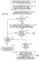
- FIGS. 2A and 2B are a flow chart of a method for controlling a torque converter clutch according to an embodiment of the present invention.
- FIG. 1 a schematic illustration of an exemplary powertrain system is shown that includes an engine 10 having an output shaft 12 and an automatic transmission 14 having an input shaft 16 and an output shaft 18 . Positioned between engine output shaft 12 and transmission input shaft 16 is a torque converter 20 .
- Torque converter 20 includes an impeller 22 operatively connected to engine output shaft 12 , a turbine 24 operatively connected to transmission input shaft 16 , and a stator 26 situated between impeller 22 and turbine 24 .
- Torque converter 20 also includes a lockup clutch 28 that is selectively engaged to mechanically connect impeller 22 for rotation with turbine 24 .
- Lockup clutch 28 may be completely engaged, whereby impeller 22 rotates together with turbine 24 without substantial slip, or may be partially engaged, whereby impeller 22 rotates together with turbine 24 with some degree of slip. Lockup clutch 28 may be operated hydraulically, for example, by a hydraulic solenoid (not shown). It will be appreciated that torque converter 20 is not limited to the design shown in FIG. 1 and that other torque converter designs are within the scope of this invention.
- the illustrated powertrain system also includes a controller 30 , such as a microprocessor-based controller having, for example, an input/output device, a central processing unit, a random access memory and/or a read-only memory (none shown).
- Controller 30 may be a transmission controller, for example, or may include or be integrated in another vehicle controller, such as a main vehicle controller or engine controller.
- Controller 30 receives powertrain operating parameter information from various sensors 32 a - e and outputs signals for controlling, among other things, operation of lockup clutch 28 .
- Sensors 32 a - e may include, without limitation, an engine speed sensor 32 a , a turbine speed sensor 32 b , an output shaft speed sensor 32 c , a throttle position sensor 32 d and a fluid flow sensor 32 e .
- Engine speed sensor 32 a detects, for example, revolution of engine output shaft 12 and generates a signal indicative of the detected engine revolution.
- the turbine speed sensor 32 b detects, for example, revolution of transmission input shaft 16 and generates a signal indicative of the detected transmission input shaft speed.
- Output shaft speed sensor 32 c detects, for example, revolution of transmission output shaft 18 and generates a signal indicative of the detected transmission output shaft revolution.
- the throttle position sensor 32 d detects, for example, position or degree of opening of the engine throttle or throttle pedal position and generates a signal indicative of the detected throttle opening or throttle pedal position. Certain operating parameter information may also be calculated based on other detected operating parameter information. For example, flywheel torque may be calculated based on a given engine speed and engine horsepower rating.
- fluid is meant to encompass a variety of fluids that can be utilized in similar environments, including air and/or fuel.
- fluid flow refers to and encompasses the flow of such fluids.
- fluid flow may be synonymous with air flow.
- the associated fluid flow may correspond to fuel flow.
- controller 30 may first establish minimum powertrain operating conditions, such as, for example, turbine speed and transmission oil temperature (step 100 ), prior to controlling lockup clutch 28 . If minimum powertrain operating conditions are established, controller 30 may then obtain (e.g., calculate or measure) powertrain operating parameter information, such as, engine speed, turbine speed, flywheel torque and engine fluid flow (step 102 ). Based on the obtained powertrain operating parameter information, controller 30 may then determine (e.g., calculate) a torque converter speed ratio based on the ratio between turbine 24 speed and impeller 22 speed (step 104 ).
- minimum powertrain operating conditions such as, for example, turbine speed and transmission oil temperature (step 100 )
- controller 30 may then obtain (e.g., calculate or measure) powertrain operating parameter information, such as, engine speed, turbine speed, flywheel torque and engine fluid flow (step 102 ). Based on the obtained powertrain operating parameter information, controller 30 may then determine (e.g., calculate) a torque converter speed ratio based on the ratio between turbine 24 speed and impeller 22 speed (step 104
- the speed ratio is then compared to a specified or predetermined limit (step 106 ).
- a specified or predetermined limit As used herein, the term “specified” is used to mean specified or predetermined. If the speed ratio is not greater than a specified limit, it can be determined if the clutch is currently in control (step 114 ). If not, the lockup clutch 28 is not engaged or is disengaged through an appropriate control scheme, such as, for example, forcing a duty cycle timer to equal zero (0) and turning the torque converter clutch solenoid off (step 108 ).
- an NVH target slip limit can be applied (step 116 ) and certain updates can occur (see e.g., step 118 ), for example, prior to a comparison of filtered engine fluid flow with actual engine fluid flow (e.g., step 126 ).
- controller 30 may then determine a target torque converter slip based on, for example, turbine speed, percent engine power and/or engine throttle position (step 110 ). If desired, controller 30 may have stored in a memory a retrievable data matrix or table that contains desired values of torque slip mapped against various operating states associated with the vehicle or various components of the vehicle. These values may be specified or predetermined to meet, among other things, torque multiplication demand and torque-variation suppression demand required for varying vehicle-operating states and noise, vibration and harshness (NVH) conditions.
- NSH vibration and harshness
- the NVH conditions may vary according to a particular gear selected in the transmission or the speed of turbine 24 , for example, and the desired values of torque slip can be selected to limit vehicle NVH during a corresponding operating state.
- controller 30 may receive vehicle operating information, such as engine speed, throttle position and vehicle speed, which describe a current operating state of the vehicle, and perform a table look-up operation of the desired slip table (based on input variables) to determine a desired slip based on a NVH limit.
- the target slip can then be compared to the desired slip based on a NVH limit (step 112 ). If the target slip is not less than (or, as may be desired, generally equal to) the NVH Limit or desired slip, then, the system may proceed as previously described in connection with illustrated step 114 . Alternatively, if the target slip does exceed the desired slip based on a NVH limit, controller 30 controls torque transmission by the lockup clutch 28 to decrease the deviation between the target slip and desired slip.
- controller 30 determines a lockup clutch engagement force command, which the controller then translates into a duty cycle signal.
- controller 30 determines a lockup clutch engagement force command, which the controller then translates into a duty cycle signal.
- the solenoid is controlled by the duty cycle signal.
- increasing the duty of the solenoid causes the lockup clutch 28 engagement force to increase, while decreasing the duty causes the lockup clutch engagement force to decrease.
- lockup clutch 28 it may be determined whether or not lockup clutch 28 is currently in control (step 120 ) after it is determined that the target slip exceeds the desired slip (step 112 ). If lockup clutch 28 is not in control, an initial feed forward control term may be determined, based on, for example, desired slip and flywheel torque or engine power, and the non-linear duty cycle control for lockup clutch 28 may be initialized (step 122 ). Alternatively, if lockup clutch 28 is in control, the feed forward control term may be updated and various error correction terms to the duty cycle control may be updated, such as proportional, integral and derivative error correction terms (step 124 ).
- the duty cycle may be further adjusted according to a change in engine fluid flow.
- controller 30 may compare filtered engine fluid flow with actual engine fluid flow (step 126 ).
- the change in engine fluid flow, or “delta,” is then compared to a given or predetermined threshold, such as a positive or negative trigger threshold (step 128 ). If the associated delta is outside the given or predetermined threshold, then the duty cycle is updated to include a given or predetermined transient offset effect on the torque converter slip (step 130 ).
- the duty cycle is delivered to the lockup clutch solenoid unadjusted (step 132 ).
- first value is compared to a second value
- comparison need not be limited to the comparative assessment as expressed, and may instead be made using other analytical assessments without departing from the scope and spirit of the invention.
- a first value such as a speed ratio
- a second value such as a limit
- the resultant response or action could instead, for example, be dependent upon an assessment as to whether the first value is equal to the second value or whether the first value is equal to or greater than the second value, i.e., whether the first value “meets or exceeds” a given second value.
- a first value is compared to a second value (for instance at element 112 ) to determine if the first value “is less than” or “does not meet or exceed” a second value.
- the positive (or “yes”) result may instead be set so as to have the desired resulting (affirmative) effect when the first value equals the second value.
- the affirmative (“yes”) result being based upon a Target Slip being less than an NVH Limit
Abstract
Description
Claims (17)
Priority Applications (1)
| Application Number | Priority Date | Filing Date | Title |
|---|---|---|---|
| US11/422,991 US7854683B2 (en) | 2006-06-08 | 2006-06-08 | Torque converter clutch control |
Applications Claiming Priority (1)
| Application Number | Priority Date | Filing Date | Title |
|---|---|---|---|
| US11/422,991 US7854683B2 (en) | 2006-06-08 | 2006-06-08 | Torque converter clutch control |
Publications (2)
| Publication Number | Publication Date |
|---|---|
| US20070287594A1 US20070287594A1 (en) | 2007-12-13 |
| US7854683B2 true US7854683B2 (en) | 2010-12-21 |
Family
ID=38822649
Family Applications (1)
| Application Number | Title | Priority Date | Filing Date |
|---|---|---|---|
| US11/422,991 Expired - Fee Related US7854683B2 (en) | 2006-06-08 | 2006-06-08 | Torque converter clutch control |
Country Status (1)
| Country | Link |
|---|---|
| US (1) | US7854683B2 (en) |
Cited By (8)
| Publication number | Priority date | Publication date | Assignee | Title |
|---|---|---|---|---|
| US20090005218A1 (en) * | 2007-06-26 | 2009-01-01 | Gary Lowe | Systems and methods for non-linear proportional and derivative control during vehicle garage shifts |
| US20090098978A1 (en) * | 2007-10-11 | 2009-04-16 | Gm Global Technology Operations, Inc. | Torque Converter Control Method And Apparatus |
| US20100204011A1 (en) * | 2009-01-13 | 2010-08-12 | Toyota Jidosha Kabushiki Kaisha | Vehicle controller and control method |
| US20120035819A1 (en) * | 2010-08-04 | 2012-02-09 | Gm Global Technology Operations, Inc. | Real time estimation algorithm for torque converter clutch feed forward pressure for eccc control |
| US9303701B2 (en) | 2014-07-16 | 2016-04-05 | Ford Global Technologies, Llc | Method of controlling a transmission having an impeller clutch |
| US9393947B2 (en) | 2013-03-07 | 2016-07-19 | Ford Global Technologies, Llc | Torsional damping using a torque convertor bypass clutch |
| US20200256459A1 (en) * | 2019-02-11 | 2020-08-13 | GM Global Technology Operations LLC | Model predictive control of torque converter clutch slip |
| US20220163108A1 (en) * | 2020-11-20 | 2022-05-26 | Honda Motor Co., Ltd. | Control device |
Families Citing this family (19)
| Publication number | Priority date | Publication date | Assignee | Title |
|---|---|---|---|---|
| JP4238845B2 (en) * | 2005-06-22 | 2009-03-18 | トヨタ自動車株式会社 | Control device for vehicle drive device |
| US7988597B2 (en) * | 2006-09-27 | 2011-08-02 | GM Global Technology Operations LLC | Method and apparatus for controlling a torque converter clutch |
| US8010265B2 (en) * | 2007-12-07 | 2011-08-30 | GM Global Technology Operations LLC | Effective driveline vibration detection algorithm in transmission TCC slip control |
| US8630778B2 (en) * | 2008-08-08 | 2014-01-14 | Honda Motor Co., Ltd. | Controlling a throttle for fuel cut acquisition |
| US8600631B2 (en) | 2011-05-20 | 2013-12-03 | GM Global Technology Operations LLC | Engine speed assist torque converter clutch control |
| US9283946B2 (en) * | 2011-10-06 | 2016-03-15 | Toyota Jidosha Kabushiki Kaisha | Vehicle drive apparatus |
| US8882636B2 (en) * | 2012-11-27 | 2014-11-11 | Ford Global Technologies, Llc | Adjusting clutch slip based on sensed parameter of transmission shaft to control NVH level in vehicle powertrain |
| US9879769B2 (en) * | 2016-04-07 | 2018-01-30 | GM Global Technology Operations LLC | Torque converter clutch slip control |
| US10944352B2 (en) | 2018-03-19 | 2021-03-09 | Tula eTechnology, Inc. | Boosted converter for pulsed electric machine control |
| US11623529B2 (en) | 2018-03-19 | 2023-04-11 | Tula eTechnology, Inc. | Pulse modulated control with field weakening for improved motor efficiency |
| JP7082679B2 (en) | 2018-03-19 | 2022-06-08 | トゥラ イーテクノロジー,インコーポレイテッド | Pulsed electromechanical control |
| US11628730B2 (en) | 2021-01-26 | 2023-04-18 | Tula eTechnology, Inc. | Pulsed electric machine control |
| JP2024510092A (en) | 2021-03-15 | 2024-03-06 | トゥラ イーテクノロジー,インコーポレイテッド | Waveform optimization method for electric motors |
| US11695361B2 (en) | 2021-06-14 | 2023-07-04 | Tula eTechnology, Inc. | Electric machines with efficient torque transitions |
| US11557996B1 (en) | 2021-07-08 | 2023-01-17 | Tula eTechnology, Inc. | Methods of reducing vibrations for electric motors |
| US11345241B1 (en) | 2021-08-12 | 2022-05-31 | Tula eTechnology, Inc. | Method of optimizing system efficiency for battery powered electric motors |
| US11916498B2 (en) | 2021-09-08 | 2024-02-27 | Tule eTechnology Inc. | Electric machine torque adjustment based on waveform integer multiples |
| WO2023069131A1 (en) | 2021-10-18 | 2023-04-27 | Tula eTechnology, Inc. | Mechanical and electromechanical arrangements for field-weakening of an electric machine that utilizes permanent magnets |
| US11888424B1 (en) | 2022-07-18 | 2024-01-30 | Tula eTechnology, Inc. | Methods for improving rate of rise of torque in electric machines with stator current biasing |
Citations (26)
| Publication number | Priority date | Publication date | Assignee | Title |
|---|---|---|---|---|
| US3693478A (en) * | 1971-01-06 | 1972-09-26 | Gen Motors Corp | Transmission having a converter clutch and a control |
| US4071125A (en) * | 1976-07-21 | 1978-01-31 | Gardner-Denver Company | Power transmission with torque converter lockup clutch |
| US4318312A (en) * | 1978-07-31 | 1982-03-09 | Nissan Motor Co., Ltd. | Gearshift control system for automatic transmissions using air flow sensor |
| US4428467A (en) * | 1981-03-31 | 1984-01-31 | Mitsubishi Jidosha Kogyo Kabushiki Kaisha | Friction clutch control device |
| US4577737A (en) * | 1982-08-02 | 1986-03-25 | Nissan Motor Co., Ltd. | Lock-up torque converter and method for controlling clutch slip in lock-up torque converter |
| US4593581A (en) * | 1984-02-24 | 1986-06-10 | Aisin Seiki Kabushiki Kaisha | Microprocessor controlled system and method for increasing the fuel flow to the prime mover of a power delivery system having a continuously variable ratio transmission upon a commanded increase in power delivery |
| US4706790A (en) * | 1986-07-17 | 1987-11-17 | General Motors Corporation | Gain scheduling technique for a closed loop slip control system |
| US4774858A (en) * | 1975-09-25 | 1988-10-04 | Ganoung David P | Engine control apparatus for improved fuel economy |
| US4875391A (en) * | 1988-04-29 | 1989-10-24 | Chrysler Motors Corporation | Electronically-controlled, adaptive automatic transmission system |
| US4940122A (en) | 1988-02-15 | 1990-07-10 | Mazda Motor Corporation | Slip control system for torque converter of automatic transmission |
| US5129286A (en) | 1991-06-27 | 1992-07-14 | Saturn Corporation | Engine torque management for engine speed flare suppression for clutch-to-clutch-upshifting |
| US5226513A (en) * | 1990-11-27 | 1993-07-13 | Nissan Motor Co., Ltd. | Torque converter lockup clutch control apparatus |
| US5413539A (en) | 1992-08-10 | 1995-05-09 | Ford Motor Company | Control system for controlling engagement of an automatic transmission torque converter clutch |
| US5468196A (en) * | 1992-03-02 | 1995-11-21 | Hitachi, Ltd. | Method and an apparatus for controlling a car equipped with an automatic transmission having a lockup clutch |
| US5498217A (en) * | 1993-09-17 | 1996-03-12 | Mitsubishi Jidosha Kogyo Kabushiki Kaisha | Control method of vehicle engine arranged in association with fluid coupling having clutch |
| US5527238A (en) * | 1995-04-10 | 1996-06-18 | Ford Motor Company | Automatic transmission bypass clutch slip control using nonlinear nverse dynamics |
| US5577980A (en) | 1995-06-30 | 1996-11-26 | General Motors Corporation | Shift flare control |
| US5625558A (en) * | 1990-11-29 | 1997-04-29 | Mitsubishi Jidosha Kogyo Kabushiki Kaisha | Drive-by-wire vehicle engine output control system |
| US5890468A (en) * | 1994-01-25 | 1999-04-06 | Komatsu Ltd. | Differential driving supercharger and method for controlling the same |
| US6039675A (en) * | 1997-09-19 | 2000-03-21 | Nissan Motor Co., Ltd. | Slip control system for torque converter |
| US6063004A (en) * | 1996-11-29 | 2000-05-16 | Hitachi, Ltd. | Control apparatus and control method for an engine powertrain of a vehicle |
| US6085136A (en) | 1996-07-26 | 2000-07-04 | Nissan Motor Co., Ltd. | Torque converter lockup strategy |
| US6132336A (en) * | 1997-09-05 | 2000-10-17 | Nissan Motor Co., Ltd. | Slip control apparatus for torque converter |
| US6537178B1 (en) * | 1999-09-30 | 2003-03-25 | Nissan Motor Co., Ltd. | Lockup control device for transmission |
| US20040157705A1 (en) * | 2000-02-28 | 2004-08-12 | Mazda Motor Corporation | Transmission control device |
| US20060094564A1 (en) * | 2004-10-01 | 2006-05-04 | Jatco Ltd | Control of lock-up clutch |
-
2006
- 2006-06-08 US US11/422,991 patent/US7854683B2/en not_active Expired - Fee Related
Patent Citations (27)
| Publication number | Priority date | Publication date | Assignee | Title |
|---|---|---|---|---|
| US3693478A (en) * | 1971-01-06 | 1972-09-26 | Gen Motors Corp | Transmission having a converter clutch and a control |
| US4774858A (en) * | 1975-09-25 | 1988-10-04 | Ganoung David P | Engine control apparatus for improved fuel economy |
| US4071125A (en) * | 1976-07-21 | 1978-01-31 | Gardner-Denver Company | Power transmission with torque converter lockup clutch |
| US4318312A (en) * | 1978-07-31 | 1982-03-09 | Nissan Motor Co., Ltd. | Gearshift control system for automatic transmissions using air flow sensor |
| US4428467A (en) * | 1981-03-31 | 1984-01-31 | Mitsubishi Jidosha Kogyo Kabushiki Kaisha | Friction clutch control device |
| US4577737A (en) * | 1982-08-02 | 1986-03-25 | Nissan Motor Co., Ltd. | Lock-up torque converter and method for controlling clutch slip in lock-up torque converter |
| US4593581A (en) * | 1984-02-24 | 1986-06-10 | Aisin Seiki Kabushiki Kaisha | Microprocessor controlled system and method for increasing the fuel flow to the prime mover of a power delivery system having a continuously variable ratio transmission upon a commanded increase in power delivery |
| US4706790A (en) * | 1986-07-17 | 1987-11-17 | General Motors Corporation | Gain scheduling technique for a closed loop slip control system |
| US4940122A (en) | 1988-02-15 | 1990-07-10 | Mazda Motor Corporation | Slip control system for torque converter of automatic transmission |
| US4875391A (en) * | 1988-04-29 | 1989-10-24 | Chrysler Motors Corporation | Electronically-controlled, adaptive automatic transmission system |
| US5226513A (en) * | 1990-11-27 | 1993-07-13 | Nissan Motor Co., Ltd. | Torque converter lockup clutch control apparatus |
| US5625558A (en) * | 1990-11-29 | 1997-04-29 | Mitsubishi Jidosha Kogyo Kabushiki Kaisha | Drive-by-wire vehicle engine output control system |
| US5129286A (en) | 1991-06-27 | 1992-07-14 | Saturn Corporation | Engine torque management for engine speed flare suppression for clutch-to-clutch-upshifting |
| US5468196A (en) * | 1992-03-02 | 1995-11-21 | Hitachi, Ltd. | Method and an apparatus for controlling a car equipped with an automatic transmission having a lockup clutch |
| US5580334A (en) * | 1992-03-02 | 1996-12-03 | Hitachi, Ltd. | Method and an apparatus for controlling a car equipped with an automatic transmission having a lockup clutch |
| US5413539A (en) | 1992-08-10 | 1995-05-09 | Ford Motor Company | Control system for controlling engagement of an automatic transmission torque converter clutch |
| US5498217A (en) * | 1993-09-17 | 1996-03-12 | Mitsubishi Jidosha Kogyo Kabushiki Kaisha | Control method of vehicle engine arranged in association with fluid coupling having clutch |
| US5890468A (en) * | 1994-01-25 | 1999-04-06 | Komatsu Ltd. | Differential driving supercharger and method for controlling the same |
| US5527238A (en) * | 1995-04-10 | 1996-06-18 | Ford Motor Company | Automatic transmission bypass clutch slip control using nonlinear nverse dynamics |
| US5577980A (en) | 1995-06-30 | 1996-11-26 | General Motors Corporation | Shift flare control |
| US6085136A (en) | 1996-07-26 | 2000-07-04 | Nissan Motor Co., Ltd. | Torque converter lockup strategy |
| US6063004A (en) * | 1996-11-29 | 2000-05-16 | Hitachi, Ltd. | Control apparatus and control method for an engine powertrain of a vehicle |
| US6132336A (en) * | 1997-09-05 | 2000-10-17 | Nissan Motor Co., Ltd. | Slip control apparatus for torque converter |
| US6039675A (en) * | 1997-09-19 | 2000-03-21 | Nissan Motor Co., Ltd. | Slip control system for torque converter |
| US6537178B1 (en) * | 1999-09-30 | 2003-03-25 | Nissan Motor Co., Ltd. | Lockup control device for transmission |
| US20040157705A1 (en) * | 2000-02-28 | 2004-08-12 | Mazda Motor Corporation | Transmission control device |
| US20060094564A1 (en) * | 2004-10-01 | 2006-05-04 | Jatco Ltd | Control of lock-up clutch |
Cited By (14)
| Publication number | Priority date | Publication date | Assignee | Title |
|---|---|---|---|---|
| US20090005218A1 (en) * | 2007-06-26 | 2009-01-01 | Gary Lowe | Systems and methods for non-linear proportional and derivative control during vehicle garage shifts |
| US8046144B2 (en) * | 2007-06-26 | 2011-10-25 | Chrysler Group Llc | Systems and methods for non-linear proportional and derivative control during vehicle garage shifts |
| US8100802B2 (en) * | 2007-10-11 | 2012-01-24 | GM Global Technology Operations LLC | Torque converter control method and apparatus |
| US20090098978A1 (en) * | 2007-10-11 | 2009-04-16 | Gm Global Technology Operations, Inc. | Torque Converter Control Method And Apparatus |
| US8210988B2 (en) * | 2009-01-13 | 2012-07-03 | Toyota Jidosha Kabushiki Kaisha | Vehicle controller and control method |
| US20100204011A1 (en) * | 2009-01-13 | 2010-08-12 | Toyota Jidosha Kabushiki Kaisha | Vehicle controller and control method |
| US20120035819A1 (en) * | 2010-08-04 | 2012-02-09 | Gm Global Technology Operations, Inc. | Real time estimation algorithm for torque converter clutch feed forward pressure for eccc control |
| US8463515B2 (en) * | 2010-08-04 | 2013-06-11 | GM Global Technology Operations LLC | Real time estimation algorithm for torque converter clutch feed forward pressure for ECCC control |
| US9393947B2 (en) | 2013-03-07 | 2016-07-19 | Ford Global Technologies, Llc | Torsional damping using a torque convertor bypass clutch |
| US9303701B2 (en) | 2014-07-16 | 2016-04-05 | Ford Global Technologies, Llc | Method of controlling a transmission having an impeller clutch |
| US20200256459A1 (en) * | 2019-02-11 | 2020-08-13 | GM Global Technology Operations LLC | Model predictive control of torque converter clutch slip |
| US10859159B2 (en) * | 2019-02-11 | 2020-12-08 | GM Global Technology Operations LLC | Model predictive control of torque converter clutch slip |
| US20220163108A1 (en) * | 2020-11-20 | 2022-05-26 | Honda Motor Co., Ltd. | Control device |
| US11480247B2 (en) * | 2020-11-20 | 2022-10-25 | Honda Motor Co., Ltd. | Control device |
Also Published As
| Publication number | Publication date |
|---|---|
| US20070287594A1 (en) | 2007-12-13 |
Similar Documents
| Publication | Publication Date | Title |
|---|---|---|
| US7854683B2 (en) | Torque converter clutch control | |
| US7967727B2 (en) | Clutch control device | |
| US7641031B2 (en) | Control apparatus for vehicle | |
| JP4389748B2 (en) | Engine control device | |
| JP2719786B2 (en) | Slip control device for torque converter | |
| JP4092504B2 (en) | Slip control device for torque converter | |
| US20080271966A1 (en) | Using inferred torque converter impeller speed to control an impeller clutch | |
| US7324886B2 (en) | Powertrain control apparatus and method | |
| JPH0886356A (en) | Slip controller of lock-up clutch for vehicle | |
| EP2169252B1 (en) | Clutch controlling apparatus for vehicle | |
| US9341263B2 (en) | Vehicle control device | |
| JP4743289B2 (en) | Control device for vehicle drive device | |
| JP3890478B2 (en) | Slip control device for torque converter | |
| US6471620B2 (en) | Control method for automatic transmission | |
| JP4013725B2 (en) | Torque converter control device | |
| JP3518648B2 (en) | Lockup control device for automatic transmission | |
| US6009988A (en) | Lock-up control device | |
| US7678019B2 (en) | Control device and control method for friction engagement element | |
| JP3998007B2 (en) | Torque converter lockup control device | |
| JP2004324847A (en) | Slip control device of torque converter | |
| JP4082700B2 (en) | Slip control device for torque converter | |
| JP2008025376A (en) | Control device and control method for power train, program executing the control method, and recording medium recording the program | |
| JP2008303958A (en) | Lock-up control device for automatic transmission | |
| KR100357591B1 (en) | A method for controlling damper clutch at a slip connection state | |
| WO2020026717A1 (en) | Slip control device for torque converter |
Legal Events
| Date | Code | Title | Description |
|---|---|---|---|
| AS | Assignment |
Owner name: DAIMLERCHRYSLER CORPORATION, MICHIGAN Free format text: ASSIGNMENT OF ASSIGNORS INTEREST;ASSIGNORS:DEGEORGE, JOHN W.;DADA, JAVED A.;SIVASUBRAMANIAN, HARISH;AND OTHERS;REEL/FRAME:018076/0036;SIGNING DATES FROM 20060428 TO 20060606 Owner name: DAIMLERCHRYSLER CORPORATION, MICHIGAN Free format text: ASSIGNMENT OF ASSIGNORS INTEREST;ASSIGNORS:DEGEORGE, JOHN W.;DADA, JAVED A.;SIVASUBRAMANIAN, HARISH;AND OTHERS;SIGNING DATES FROM 20060428 TO 20060606;REEL/FRAME:018076/0036 |
|
| AS | Assignment |
Owner name: WILMINGTON TRUST COMPANY, DELAWARE Free format text: GRANT OF SECURITY INTEREST IN PATENT RIGHTS - FIRST PRIORITY;ASSIGNOR:CHRYSLER LLC;REEL/FRAME:019773/0001 Effective date: 20070803 Owner name: WILMINGTON TRUST COMPANY,DELAWARE Free format text: GRANT OF SECURITY INTEREST IN PATENT RIGHTS - FIRST PRIORITY;ASSIGNOR:CHRYSLER LLC;REEL/FRAME:019773/0001 Effective date: 20070803 |
|
| AS | Assignment |
Owner name: WILMINGTON TRUST COMPANY, DELAWARE Free format text: GRANT OF SECURITY INTEREST IN PATENT RIGHTS - SECOND PRIORITY;ASSIGNOR:CHRYSLER LLC;REEL/FRAME:019767/0810 Effective date: 20070803 Owner name: WILMINGTON TRUST COMPANY,DELAWARE Free format text: GRANT OF SECURITY INTEREST IN PATENT RIGHTS - SECOND PRIORITY;ASSIGNOR:CHRYSLER LLC;REEL/FRAME:019767/0810 Effective date: 20070803 |
|
| AS | Assignment |
Owner name: DAIMLERCHRYSLER COMPANY LLC, MICHIGAN Free format text: CHANGE OF NAME;ASSIGNOR:DAIMLERCHRYSLER CORPORATION;REEL/FRAME:021915/0760 Effective date: 20070329 Owner name: CHRYSLER LLC, MICHIGAN Free format text: CHANGE OF NAME;ASSIGNOR:DAIMLERCHRYSLER COMPANY LLC;REEL/FRAME:021915/0772 Effective date: 20070727 Owner name: DAIMLERCHRYSLER COMPANY LLC,MICHIGAN Free format text: CHANGE OF NAME;ASSIGNOR:DAIMLERCHRYSLER CORPORATION;REEL/FRAME:021915/0760 Effective date: 20070329 Owner name: CHRYSLER LLC,MICHIGAN Free format text: CHANGE OF NAME;ASSIGNOR:DAIMLERCHRYSLER COMPANY LLC;REEL/FRAME:021915/0772 Effective date: 20070727 |
|
| AS | Assignment |
Owner name: US DEPARTMENT OF THE TREASURY, DISTRICT OF COLUMBI Free format text: GRANT OF SECURITY INTEREST IN PATENT RIGHTS - THIR;ASSIGNOR:CHRYSLER LLC;REEL/FRAME:022259/0188 Effective date: 20090102 Owner name: US DEPARTMENT OF THE TREASURY,DISTRICT OF COLUMBIA Free format text: GRANT OF SECURITY INTEREST IN PATENT RIGHTS - THIR;ASSIGNOR:CHRYSLER LLC;REEL/FRAME:022259/0188 Effective date: 20090102 |
|
| AS | Assignment |
Owner name: CHRYSLER LLC, MICHIGAN Free format text: RELEASE BY SECURED PARTY;ASSIGNOR:US DEPARTMENT OF THE TREASURY;REEL/FRAME:022902/0164 Effective date: 20090608 Owner name: CHRYSLER LLC,MICHIGAN Free format text: RELEASE BY SECURED PARTY;ASSIGNOR:US DEPARTMENT OF THE TREASURY;REEL/FRAME:022902/0164 Effective date: 20090608 |
|
| AS | Assignment |
Owner name: CHRYSLER LLC, MICHIGAN Free format text: RELEASE OF SECURITY INTEREST IN PATENT RIGHTS - FIRST PRIORITY;ASSIGNOR:WILMINGTON TRUST COMPANY;REEL/FRAME:022910/0498 Effective date: 20090604 Owner name: CHRYSLER LLC, MICHIGAN Free format text: RELEASE OF SECURITY INTEREST IN PATENT RIGHTS - SECOND PRIORITY;ASSIGNOR:WILMINGTON TRUST COMPANY;REEL/FRAME:022910/0740 Effective date: 20090604 Owner name: NEW CARCO ACQUISITION LLC, MICHIGAN Free format text: ASSIGNMENT OF ASSIGNORS INTEREST;ASSIGNOR:CHRYSLER LLC;REEL/FRAME:022915/0001 Effective date: 20090610 Owner name: THE UNITED STATES DEPARTMENT OF THE TREASURY, DIST Free format text: SECURITY AGREEMENT;ASSIGNOR:NEW CARCO ACQUISITION LLC;REEL/FRAME:022915/0489 Effective date: 20090610 Owner name: CHRYSLER LLC,MICHIGAN Free format text: RELEASE OF SECURITY INTEREST IN PATENT RIGHTS - FIRST PRIORITY;ASSIGNOR:WILMINGTON TRUST COMPANY;REEL/FRAME:022910/0498 Effective date: 20090604 Owner name: CHRYSLER LLC,MICHIGAN Free format text: RELEASE OF SECURITY INTEREST IN PATENT RIGHTS - SECOND PRIORITY;ASSIGNOR:WILMINGTON TRUST COMPANY;REEL/FRAME:022910/0740 Effective date: 20090604 Owner name: NEW CARCO ACQUISITION LLC,MICHIGAN Free format text: ASSIGNMENT OF ASSIGNORS INTEREST;ASSIGNOR:CHRYSLER LLC;REEL/FRAME:022915/0001 Effective date: 20090610 Owner name: THE UNITED STATES DEPARTMENT OF THE TREASURY,DISTR Free format text: SECURITY AGREEMENT;ASSIGNOR:NEW CARCO ACQUISITION LLC;REEL/FRAME:022915/0489 Effective date: 20090610 |
|
| AS | Assignment |
Owner name: CHRYSLER GROUP LLC, MICHIGAN Free format text: CHANGE OF NAME;ASSIGNOR:NEW CARCO ACQUISITION LLC;REEL/FRAME:022919/0126 Effective date: 20090610 Owner name: CHRYSLER GROUP LLC,MICHIGAN Free format text: CHANGE OF NAME;ASSIGNOR:NEW CARCO ACQUISITION LLC;REEL/FRAME:022919/0126 Effective date: 20090610 |
|
| STCF | Information on status: patent grant |
Free format text: PATENTED CASE |
|
| AS | Assignment |
Owner name: CHRYSLER GROUP GLOBAL ELECTRIC MOTORCARS LLC, NORT Free format text: RELEASE BY SECURED PARTY;ASSIGNOR:THE UNITED STATES DEPARTMENT OF THE TREASURY;REEL/FRAME:026335/0001 Effective date: 20110524 Owner name: CHRYSLER GROUP LLC, MICHIGAN Free format text: RELEASE BY SECURED PARTY;ASSIGNOR:THE UNITED STATES DEPARTMENT OF THE TREASURY;REEL/FRAME:026335/0001 Effective date: 20110524 |
|
| AS | Assignment |
Owner name: CITIBANK, N.A., NEW YORK Free format text: SECURITY AGREEMENT;ASSIGNOR:CHRYSLER GROUP LLC;REEL/FRAME:026404/0123 Effective date: 20110524 |
|
| AS | Assignment |
Owner name: CITIBANK, N.A., NEW YORK Free format text: SECURITY AGREEMENT;ASSIGNOR:CHRYSLER GROUP LLC;REEL/FRAME:026435/0652 Effective date: 20110524 |
|
| AS | Assignment |
Owner name: JPMORGAN CHASE BANK, N.A., ILLINOIS Free format text: SECURITY AGREEMENT;ASSIGNOR:CHRYSLER GROUP LLC;REEL/FRAME:032384/0640 Effective date: 20140207 |
|
| FPAY | Fee payment |
Year of fee payment: 4 |
|
| AS | Assignment |
Owner name: FCA US LLC, MICHIGAN Free format text: CHANGE OF NAME;ASSIGNOR:CHRYSLER GROUP LLC;REEL/FRAME:035553/0356 Effective date: 20141203 |
|
| AS | Assignment |
Owner name: FCA US LLC, FORMERLY KNOWN AS CHRYSLER GROUP LLC, Free format text: RELEASE OF SECURITY INTEREST RELEASING SECOND-LIEN SECURITY INTEREST PREVIOUSLY RECORDED AT REEL 026426 AND FRAME 0644, REEL 026435 AND FRAME 0652, AND REEL 032384 AND FRAME 0591;ASSIGNOR:CITIBANK, N.A.;REEL/FRAME:037784/0001 Effective date: 20151221 |
|
| AS | Assignment |
Owner name: FCA US LLC (FORMERLY KNOWN AS CHRYSLER GROUP LLC), Free format text: RELEASE BY SECURED PARTY;ASSIGNOR:CITIBANK, N.A.;REEL/FRAME:042885/0255 Effective date: 20170224 |
|
| MAFP | Maintenance fee payment |
Free format text: PAYMENT OF MAINTENANCE FEE, 8TH YEAR, LARGE ENTITY (ORIGINAL EVENT CODE: M1552) Year of fee payment: 8 |
|
| AS | Assignment |
Owner name: FCA US LLC (FORMERLY KNOWN AS CHRYSLER GROUP LLC), Free format text: RELEASE BY SECURED PARTY;ASSIGNOR:JPMORGAN CHASE BANK, N.A.;REEL/FRAME:048177/0356 Effective date: 20181113 |
|
| FEPP | Fee payment procedure |
Free format text: MAINTENANCE FEE REMINDER MAILED (ORIGINAL EVENT CODE: REM.); ENTITY STATUS OF PATENT OWNER: LARGE ENTITY |
|
| LAPS | Lapse for failure to pay maintenance fees |
Free format text: PATENT EXPIRED FOR FAILURE TO PAY MAINTENANCE FEES (ORIGINAL EVENT CODE: EXP.); ENTITY STATUS OF PATENT OWNER: LARGE ENTITY |
|
| STCH | Information on status: patent discontinuation |
Free format text: PATENT EXPIRED DUE TO NONPAYMENT OF MAINTENANCE FEES UNDER 37 CFR 1.362 |
|
| FP | Lapsed due to failure to pay maintenance fee |
Effective date: 20221221 |