US7843473B2 - Matrix display with gamma correction based on gamma characteristics pairs and different input transmittance level - Google Patents
Matrix display with gamma correction based on gamma characteristics pairs and different input transmittance level Download PDFInfo
- Publication number
- US7843473B2 US7843473B2 US10/567,015 US56701504A US7843473B2 US 7843473 B2 US7843473 B2 US 7843473B2 US 56701504 A US56701504 A US 56701504A US 7843473 B2 US7843473 B2 US 7843473B2
- Authority
- US
- United States
- Prior art keywords
- gamma
- characteristic
- pixel
- distribution area
- video signal
- Prior art date
- Legal status (The legal status is an assumption and is not a legal conclusion. Google has not performed a legal analysis and makes no representation as to the accuracy of the status listed.)
- Expired - Fee Related, expires
Links
Images


Classifications
-
- G—PHYSICS
- G09—EDUCATION; CRYPTOGRAPHY; DISPLAY; ADVERTISING; SEALS
- G09G—ARRANGEMENTS OR CIRCUITS FOR CONTROL OF INDICATING DEVICES USING STATIC MEANS TO PRESENT VARIABLE INFORMATION
- G09G3/00—Control arrangements or circuits, of interest only in connection with visual indicators other than cathode-ray tubes
- G09G3/20—Control arrangements or circuits, of interest only in connection with visual indicators other than cathode-ray tubes for presentation of an assembly of a number of characters, e.g. a page, by composing the assembly by combination of individual elements arranged in a matrix no fixed position being assigned to or needed to be assigned to the individual characters or partial characters
- G09G3/34—Control arrangements or circuits, of interest only in connection with visual indicators other than cathode-ray tubes for presentation of an assembly of a number of characters, e.g. a page, by composing the assembly by combination of individual elements arranged in a matrix no fixed position being assigned to or needed to be assigned to the individual characters or partial characters by control of light from an independent source
- G09G3/36—Control arrangements or circuits, of interest only in connection with visual indicators other than cathode-ray tubes for presentation of an assembly of a number of characters, e.g. a page, by composing the assembly by combination of individual elements arranged in a matrix no fixed position being assigned to or needed to be assigned to the individual characters or partial characters by control of light from an independent source using liquid crystals
-
- G—PHYSICS
- G02—OPTICS
- G02F—OPTICAL DEVICES OR ARRANGEMENTS FOR THE CONTROL OF LIGHT BY MODIFICATION OF THE OPTICAL PROPERTIES OF THE MEDIA OF THE ELEMENTS INVOLVED THEREIN; NON-LINEAR OPTICS; FREQUENCY-CHANGING OF LIGHT; OPTICAL LOGIC ELEMENTS; OPTICAL ANALOGUE/DIGITAL CONVERTERS
- G02F1/00—Devices or arrangements for the control of the intensity, colour, phase, polarisation or direction of light arriving from an independent light source, e.g. switching, gating or modulating; Non-linear optics
- G02F1/01—Devices or arrangements for the control of the intensity, colour, phase, polarisation or direction of light arriving from an independent light source, e.g. switching, gating or modulating; Non-linear optics for the control of the intensity, phase, polarisation or colour
- G02F1/13—Devices or arrangements for the control of the intensity, colour, phase, polarisation or direction of light arriving from an independent light source, e.g. switching, gating or modulating; Non-linear optics for the control of the intensity, phase, polarisation or colour based on liquid crystals, e.g. single liquid crystal display cells
- G02F1/133—Constructional arrangements; Operation of liquid crystal cells; Circuit arrangements
-
- G—PHYSICS
- G09—EDUCATION; CRYPTOGRAPHY; DISPLAY; ADVERTISING; SEALS
- G09G—ARRANGEMENTS OR CIRCUITS FOR CONTROL OF INDICATING DEVICES USING STATIC MEANS TO PRESENT VARIABLE INFORMATION
- G09G3/00—Control arrangements or circuits, of interest only in connection with visual indicators other than cathode-ray tubes
- G09G3/20—Control arrangements or circuits, of interest only in connection with visual indicators other than cathode-ray tubes for presentation of an assembly of a number of characters, e.g. a page, by composing the assembly by combination of individual elements arranged in a matrix no fixed position being assigned to or needed to be assigned to the individual characters or partial characters
-
- G—PHYSICS
- G09—EDUCATION; CRYPTOGRAPHY; DISPLAY; ADVERTISING; SEALS
- G09G—ARRANGEMENTS OR CIRCUITS FOR CONTROL OF INDICATING DEVICES USING STATIC MEANS TO PRESENT VARIABLE INFORMATION
- G09G2320/00—Control of display operating conditions
- G09G2320/02—Improving the quality of display appearance
- G09G2320/0271—Adjustment of the gradation levels within the range of the gradation scale, e.g. by redistribution or clipping
- G09G2320/0276—Adjustment of the gradation levels within the range of the gradation scale, e.g. by redistribution or clipping for the purpose of adaptation to the characteristics of a display device, i.e. gamma correction
-
- G—PHYSICS
- G09—EDUCATION; CRYPTOGRAPHY; DISPLAY; ADVERTISING; SEALS
- G09G—ARRANGEMENTS OR CIRCUITS FOR CONTROL OF INDICATING DEVICES USING STATIC MEANS TO PRESENT VARIABLE INFORMATION
- G09G2320/00—Control of display operating conditions
- G09G2320/02—Improving the quality of display appearance
- G09G2320/028—Improving the quality of display appearance by changing the viewing angle properties, e.g. widening the viewing angle, adapting the viewing angle to the view direction
Definitions
- the present invention relates to a matrix-type display apparatus which drives a plurality of pixels disposed in matrix form and displays an image, and its driving method.
- a liquid crystal In a liquid-crystal display apparatus where a TN (or twisted nematic) system is used, a liquid crystal has a refractive-index anisotropy, a twist orientation, or the like.
- a beam of light which passes through a liquid-crystal layer is subjected to various birefringence effects, depending upon its direction or angle. This allows a complicated visual-angle dependence to appear. For example, the whole screen image becomes whitish at an upper visual angle while the entire screen image becomes dark at a lower visual angle. Besides, light and shade are reversed within an image's low-luminance range.
- various techniques have been developed for widening a viewing angle about a luminance, a hue, a contrast characteristic, a gradation characteristic, or the like.
- Japanese Patent Laid-Open No. 5-68221 specification discloses a liquid-crystal display apparatus. If the number of times at which a signal is written in one pixel for a one-field period is n, then n+1 levels are driven using only two black and white values. The other levels are driven using a combination of a gray level and white or black level. Thereby, a ⁇ -characteristic (i.e., a transmittance characteristic according to an input level) is changed.
- a ⁇ -characteristic i.e., a transmittance characteristic according to an input level
- a synthetic ⁇ -characteristic is used which is obtained through a synthesis after two types of ⁇ -characteristics are changed so that the distribution area ratios are the same. Therefore, if a viewing angle is deflected, then in accordance with a transmittance, a ⁇ -characteristic after synthesized deviates largely from an intrinsic ⁇ -characteristic. Even in this case, a good viewing angle characteristic cannot be realized at a wide-ranging transmittance.
- a matrix-type display apparatus which drives a display panel including a plurality of pixels disposed in matrix form and displays an image, characterized by including: a converting means for ⁇ -converting an input video signal, using n (which is an integer of two or above) pairs of ⁇ -characteristics which are made up of first and second ⁇ -characteristics different from each other; and a selecting means for selecting one pair of ⁇ -characteristics from among the n pairs of ⁇ -characteristics according to a transmittance to be used for display, and selecting an output supplied to the display panel from among the 2n outputs which are ⁇ -corrected by the converting means, so that a first distribution area ratio of pixels driven by the video signal ⁇ -corrected by use of the first ⁇ -characteristic of the selected pairs of ⁇ -characteristics and a second distribution area ratio of pixels driven by the video signal ⁇ -corrected by use of the second ⁇ -characteristic of the selected pairs of ⁇ -characteristics are equal to
- a video signal is ⁇ -converted, using n (which is an integer of two or above) pairs of ⁇ -characteristics which are made up of first and second ⁇ -characteristics different from each other. Then, one pair of ⁇ -characteristics are selected from among the n pairs of ⁇ -characteristics according to a transmittance to be used for display, and an output supplied to the display panel is selected from among the 2n outputs so that a first distribution area ratio of pixels driven by the video signal ⁇ -corrected by use of the first ⁇ -characteristic of the selected pairs of ⁇ -characteristics and a second distribution area ratio of pixels driven by the video signal ⁇ -corrected by use of the second ⁇ -characteristic of the selected pairs of ⁇ -characteristics are equal to a distribution area ratio specified in advance for the selected pairs of ⁇ -characteristics.
- the video signals ⁇ -corrected by use of the first and the second ⁇ -characteristics suitable for a transmittance to be used for display are selected to be a distribution area ratio suitable for the transmittance to be used for display. This helps realize a good viewing angle characteristic at a wide-ranging transmittance.
- the selecting means select an output supplied to the display panel from among the 2n outputs which are ⁇ -corrected by the converting means, so that the first distribution area ratio and the second distribution area ratio are equal to the distribution area ratio in a block unit of (n+1) pixels per block.
- the first distribution area ratio and the second distribution area ratio for each pair of ⁇ -characteristics should be selected out of k/(n+1) and (1 ⁇ k)/(n+1), if k is an integer of one to n.
- the first distribution area ratio and the second distribution area ratio can be equated with the distribution area ratio suitable for a transmittance to be used for display. Therefore, using a general display panel in which each pixel has one and the same formation, a good viewing angle characteristic can be realized at a wide-ranging transmittance.
- the first distribution area ratio and the second distribution area ratio can be equated with the distribution area ratio suitable for a transmittance to be used for display. Therefore, using a display panel which includes two types of sub-pixels, a good viewing angle characteristic can be realized at a wide-ranging transmittance.
- the first distribution area ratio and the second ⁇ -distribution area ratio for each pair of ⁇ -characteristics should be selected from among 1/(2+2m), m/(2+2m), 2/(2+2m), (1+m)/(2+2m), 2m/(2+2m), (2+m)/(2+2m), and (2m+1)/(2+2m).
- the first distribution area ratio and the second distribution area ratio can be equated with the distribution area ratio suitable for a transmittance to be used for display. Therefore, the number of distribution area ratios to be set can be raised, thus increasing the number of pairs of ⁇ -characteristics. Accordingly, using a display panel which includes two types of sub-pixels, a good viewing angle characteristic can be realized at a wide-ranging transmittance.
- the second pixel area Sb satisfy the relation of 1.2Sa ⁇ Sb ⁇ 2Sa. In this case, without lowering a display definition, using a display panel which includes two types of sub-pixels, a good viewing angle characteristic can be realized at a wide-ranging transmittance.
- the selecting means should select an output supplied to the display panel from among the 2n outputs which are ⁇ -corrected by the converting means, in a unit of one pixel made up of an R-pixel, a G-pixel and a B-pixel.
- the ⁇ -characteristic is changed in a unit of one pixel made up of an R-pixel, a G-pixel and a B-pixel. This makes it possible to simplify the configuration of the apparatus.
- the selecting means select an output supplied to the display panel from among the 2n outputs which are ⁇ -corrected by the converting means, for each of an R-pixel, a G-pixel and a B-pixel which are each set as one pixel.
- the ⁇ -characteristic can be changed in each pixel unit of an R-pixel, a G-pixel and a B-pixel. This makes it possible to simplify the configuration of the apparatus. Therefore, the ⁇ -characteristic can be used according to each characteristic of the R-pixel, the G-pixel and the B-pixel. This helps realize a good viewing angle characteristic at a wide-ranging transmittance.
- the display panel should be a liquid-crystal display panel.
- a good viewing angle characteristic can be realized at a wide-ranging transmittance.
- a driving method for a matrix-type display apparatus which drives a display panel including a plurality of pixels disposed in matrix form and displays an image, characterized by including: a converting step of ⁇ -converting an input video signal, using n (which is an integer of two or above) pairs of ⁇ -characteristics which are made up of first and second ⁇ -characteristics different from each other; and a selecting step of selecting one pair of ⁇ -characteristics from among the n pairs of ⁇ -characteristics according to a transmittance to be used for display, and selecting an output supplied to the display panel from among the 2n outputs which are ⁇ -corrected in the converting step, so that a first distribution area ratio of pixels driven by the video signal ⁇ -corrected by use of the first ⁇ -characteristic of the selected pairs of ⁇ -characteristics and a second distribution area ratio of pixels driven by the video signal ⁇ -corrected by use of the second ⁇ -characteristic of the selected pairs of ⁇ -character
- a video signal is ⁇ -converted, using n (which is an integer of two or above) pairs of ⁇ -characteristics which are made up of first and second ⁇ -characteristics different from each other.
- one pair of -characteristics are selected from among the n pairs of ⁇ -characteristics according to a transmittance to be used for display, and an output supplied to the display panel is selected from among the 2n outputs so that a first distribution area ratio of pixels driven by the video signal as ⁇ corrected by use of the first ⁇ -characteristic of the selected pairs of ⁇ -characteristics and a second distribution area ratio of pixels driven by the video signal as ⁇ corrected by use of the second ⁇ -characteristic of the selected pairs of ⁇ -characteristics are equal to a distribution area ratio specified in advance for the selected pairs of ⁇ -characteristics.
- the video signals as ⁇ corrected by use of the first and the second ⁇ -characteristics suitable for a transmittance to be used for display are selected to be a distribution area ratio suitable for the transmittance to be used for display. This helps realize a good viewing angle characteristic at a wide-ranging transmittance.
- FIG. 1 is a block diagram, showing the configuration of a liquid-crystal display apparatus according to a first embodiment of the present invention.
- FIG. 2 is a graphical representation, showing an example of a first type of first ⁇ -characteristic ⁇ 1 A and second ⁇ -characteristic ⁇ 2 A which are used in the liquid-crystal display apparatus shown in FIG. 1 .
- FIG. 3 is a graphical representation, showing an example of a second type of first ⁇ -characteristic ⁇ 1 B and second ⁇ -characteristic ⁇ 2 B which are used in the liquid-crystal display apparatus shown in FIG. 1 .
- FIG. 4 is a graphical representation, showing an example of a third type of first ⁇ -characteristic ⁇ 1 C and second ⁇ -characteristic ⁇ 2 C which are used in the liquid-crystal display apparatus shown in FIG. 1 .
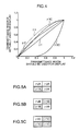
- FIGS. 5A to 5C are illustrations, showing an example of change patterns for first to third types of pairs of ⁇ -characteristics which are used in the liquid-crystal display apparatus shown in FIG. 1 .
- FIG. 6 is a graphical representation, showing an example of the control of a ⁇ -characteristic in accordance with a transmittance in the liquid-crystal display apparatus shown in FIG. 1 .
- FIG. 7 is a block diagram, showing the configuration of a liquid-crystal display apparatus according to a second embodiment of the present invention.
- FIG. 8 is an illustration, showing the configuration of a pixel in a liquid-crystal panel shown in FIG. 7 .
- FIG. 9 is a graphical representation, showing an example of a first type of first ⁇ -characteristic ⁇ 1 A, a first type of second ⁇ -characteristic ⁇ 2 A, a second type of first ⁇ -characteristic ⁇ 1 B and a second type of second ⁇ -characteristic ⁇ 2 B which are used in the liquid-crystal display apparatus shown in FIG. 7 .
- FIG. 10 is a graphical representation, showing an example of the control of a ⁇ -characteristic in accordance with a transmittance in the liquid-crystal display apparatus shown in FIG. 7 .
- FIG. 11 is a block diagram, showing the configuration of a liquid-crystal display apparatus according to a third embodiment of the present invention.
- FIG. 12 is an illustration, showing the configuration of a pixel in a liquid-crystal panel shown in FIG. 11 .
- FIG. 13 is a graphical representation, showing an example of first to seventh types of first ⁇ -characteristics ⁇ 1 A to ⁇ 1 G and second ⁇ -characteristics ⁇ 2 A to ⁇ 2 G which are used in the liquid-crystal display apparatus shown in FIG. 11 .
- FIG. 14 is a graphical representation, showing an example of the control of a ⁇ -characteristic in accordance with a transmittance in the liquid-crystal display apparatus shown in FIG. 11 .
- FIG. 15 is a graphical representation, showing a first partially-enlarged part of the graphical representation shown in FIG. 14 .
- FIG. 16 is a graphical representation, showing a second partially-enlarged part of the graphical representation shown in FIG. 14 .
- FIG. 17 is a graphical representation, showing a third partially-enlarged part of the graphical representation shown in FIG. 14 .
- FIG. 18 is a graphical representation, showing a fourth partially-enlarged part of the graphical representation shown in FIG. 14 .
- a matrix-type display apparatus according to the present invention will be described with reference to the attached drawings.
- a liquid-crystal display apparatus is described as an example of the matrix-type display apparatus.
- the matrix-type display apparatus to which the present invention is applied is not limited especially to this example. It can be similarly applied to another matrix-type display apparatus such as an organic EL (or electro-luminescence) display apparatus, as long as it has a viewing angle characteristic.
- FIG. 1 is a block diagram, showing the configuration of a liquid-crystal display apparatus according to a first embodiment of the present invention.
- the liquid-crystal display apparatus shown in FIG. 1 includes: a ⁇ 1 A converter circuit 1 a ; a ⁇ 1 B converter circuit 1 b ; a ⁇ 1 C converter circuit 1 c ; a ⁇ 2 A converter circuit 2 a ; a ⁇ 2 B converter circuit 2 b ; a ⁇ 2 C converter circuit 2 c ; selectors 3 to 5 ; a panel equalizer circuit 6 ; a ⁇ -decision circuit 7 ; a distribution decision circuit 8 ; a driving circuit 9 ; and a liquid-crystal panel 10 .
- a video signal IS is inputted which is separate according to each color component of R, G, B.
- a synchronizing signal HV of the video signal IS is inputted, such as a vertical synchronizing signal and a horizontal synchronizing signal.
- the video signal IS and the synchronizing signal HV are signals which are inputted from a predetermined video output circuit (not shown) or the like.
- the ⁇ 1 A converter circuit 1 a ⁇ -converts the video signal IS, using a first type of first ⁇ -characteristic ⁇ 1 A. Then, it outputs the ⁇ -corrected video signal to the selector 3 .
- the ⁇ 2 A converter circuit 2 a ⁇ -converts the video signal IS, using a first type of second ⁇ -characteristic ⁇ 2 A. Then, it outputs the ⁇ -corrected video signal to the selector 4 .
- the first type of first ⁇ -characteristic ⁇ 1 A and second ⁇ -characteristic ⁇ 2 A are ⁇ -characteristics which are complementary to each other. They are the first type of pair of ⁇ -characteristics used for the video signal IS which has a low transmittance.
- FIG. 2 is a graphical representation, showing an example of the first type of first ⁇ -characteristic ⁇ 1 A and second ⁇ -characteristic ⁇ 2 A which are used in the liquid-crystal display apparatus shown in FIG. 1 .
- the first type of ⁇ -characteristics i.e., the transmittance characteristics which correspond to an input level
- a transmittance which is equivalent to an input
- a transmittance which is equivalent to an output
- These graphs indicate ⁇ -characteristics in such a case, and each transmittance is a normalized value.
- a reference ⁇ -characteristic ⁇ f at the front vision (zero degrees) is linear.
- a ⁇ -characteristic ⁇ s at a non-front vision (e.g., horizontal 45 degrees) is shifted from ⁇ f, so that it is deteriorated.
- these reference ⁇ -characteristic ⁇ f and ⁇ -characteristic ⁇ s at a non-front vision are also the same in the following embodiments. Hence, their description is omitted below.
- the ⁇ 1 A converter circuit 1 a has the first type of first ⁇ -characteristic ⁇ 1 A
- the ⁇ 2 A converter circuit 2 a has the first type of second ⁇ -characteristic ⁇ 2 A.
- the output of the ⁇ 1 A converter circuit 1 a and the output of the ⁇ 2 A converter circuit 2 a are switched using a change pattern (described later) for a first type of pair of ⁇ -characteristics.
- the first type of first ⁇ -characteristic ⁇ 1 A and the first type of second ⁇ -characteristic ⁇ 2 A are synthesized, so that the ⁇ -characteristic after synthesized becomes a first type of synthetic ⁇ -characteristic ⁇ A.
- this first type of synthetic ⁇ -characteristic ⁇ A is compared with the reference ⁇ -characteristic ⁇ f at the front vision (zero degrees) as well as the ⁇ -characteristic ⁇ s at a non-front vision, the discrepancy between it and ⁇ f is smaller than that between it and ⁇ s. Hence, it can be seen that its characteristic is improved. Besides, the discrepancy between it and the reference ⁇ -characteristic ⁇ f can be seen to be smaller within the range where the transmittance which should be used for display is lower.
- the first type of first ⁇ -characteristic ⁇ 1 A and second ⁇ -characteristic ⁇ 2 A are determined, for example, as a reference, using the skin color of the video signal IS. This is because the skin color is a color to which humans are most visually-sensitive and visual sense characteristics on the skin color is most visible. In this respect, the other ⁇ -characteristics are also the same.
- the ⁇ 1 B converter circuit 1 b ⁇ -converts the video signal IS, using a second type of first ⁇ -characteristic ⁇ 1 B. Then, it outputs the ⁇ -corrected video signal to the selector 3 .
- the ⁇ 2 B converter circuit 2 b ⁇ -converts the video signal IS, using a second type of second ⁇ -characteristic ⁇ 2 B. Then, it outputs the ⁇ -corrected video signal to the selector 4 .
- the second type of first ⁇ -characteristic ⁇ 1 B and second ⁇ -characteristic ⁇ 2 B are ⁇ -characteristics which are complementary to each other. They are the second type of pair of ⁇ -characteristics used for the video signal IS which has an intermediate transmittance.
- FIG. 3 is a graphical representation, showing an example of the second type of first ⁇ -characteristic ⁇ 1 B and second ⁇ -characteristic ⁇ 2 B which are used in the liquid-crystal display apparatus shown in FIG. 1 .
- the ⁇ 1 B converter circuit 1 b has the second type of first ⁇ -characteristic ⁇ 1 B
- the ⁇ 2 B converter circuit 2 b has the second type of second ⁇ -characteristic ⁇ 2 B.
- the output of the ⁇ 1 B converter circuit 1 b and the output of the ⁇ 2 B converter circuit 2 b are switched using a change pattern (described later) for a second type of pair of ⁇ -characteristics.
- the second type of first ⁇ -characteristic ⁇ 1 B and the second type of second ⁇ -characteristic ⁇ 2 B are synthesized, so that the ⁇ -characteristic after synthesized becomes a second type of synthetic ⁇ -characteristic ⁇ B.
- this second type of synthetic ⁇ -characteristic ⁇ B is compared with the reference ⁇ -characteristic ⁇ f at the front vision as well as the ⁇ -characteristic ⁇ s at a non-front vision, the discrepancy between it and ⁇ f is smaller than that between it and ⁇ s.
- the discrepancy between it and the reference ⁇ -characteristic ⁇ f can be seen to be smaller within the range where the transmittance which should be used for display is intermediate.
- the ⁇ 1 C converter circuit 1 c ⁇ -converts the video signal IS, using a third type of first ⁇ -characteristic ⁇ 1 C. Then, it outputs the ⁇ -corrected video signal to the selector 3 .
- the ⁇ 2 C converter circuit 2 c ⁇ -converts the video signal IS, using a third type of second ⁇ -characteristic ⁇ 2 C. Then, it outputs the ⁇ -corrected video signal to the selector 4 .
- the third type of first ⁇ -characteristic ⁇ 1 C and second ⁇ -characteristic ⁇ 2 C are ⁇ -characteristics which are complementary to each other. They are the third type of pair of ⁇ -characteristics used for the video signal IS which has a high transmittance.
- FIG. 4 is a graphical representation, showing an example of the third type of first ⁇ -characteristic ⁇ 1 C and second ⁇ -characteristic ⁇ 2 C which are used in the liquid-crystal display apparatus shown in FIG. 1 .
- the ⁇ 1 C converter circuit 1 c has the third type of first ⁇ -characteristic ⁇ 1 C
- the ⁇ 2 C converter circuit 2 c has the third type of second ⁇ -characteristic ⁇ 2 C.
- the output of the ⁇ 1 C converter circuit 1 c and the ⁇ 2 C converter circuit 2 c are switched using a change pattern (described later) for a third type of pair of ⁇ -characteristics.
- the third type of first ⁇ -characteristic ⁇ 1 C and the third type of second ⁇ -characteristic ⁇ 2 C are synthesized, so that the y-characteristic after synthesized becomes a third type of synthetic ⁇ -characteristic ⁇ C.
- this third type of synthetic ⁇ -characteristic ⁇ C is compared with the reference ⁇ -characteristic ⁇ f at the front vision as well as the ⁇ -characteristic ⁇ s at a non-front vision, the discrepancy between it and ⁇ f is smaller than that between it and ⁇ s.
- the discrepancy between it and the reference ⁇ -characteristic ⁇ f can be seen to be smaller within the range where the transmittance which should be used for display is higher.
- a ⁇ -converter circuit is not limited especially to the above described example, and thus, various changes can be made.
- a variety of configurations can be used, such as an analog system, an arithmetic system and an ROM-table system.
- ⁇ -characteristics are not coincident over every gradation among RGB signals. Hence, it has a color-shift characteristic. Therefore, in order to restrain a change in hue or the like and correct a viewing angle, a ⁇ -converter circuit may be provided for each RGB signal.
- the panel equalizer circuit 6 is a circuit which has a conversion characteristic equivalent to an input-and-output characteristic P(x) of the liquid-crystal panel 10 . It outputs a video signal into which the video signal IS has been converted using the input-and-output characteristic P(x) of the liquid-crystal panel 10 , to the ⁇ -decision circuit 7 and the distribution decision circuit 8 .
- the distribution decision circuit 8 specifies the pixel position of the video signal IS on the display screen of the liquid-crystal panel 10 , as a reference, using the vertical synchronizing signal and horizontal synchronizing signal of the synchronizing signal HV. It also specifies a transmittance to be used for display from the video signal corrected by use of the input-and-output characteristic P(x) of the liquid-crystal panel 10 . Then, it outputs, to the selector 5 , a selection signal S 2 for changing the ⁇ -characteristic using the change pattern which corresponds beforehand to the pair of ⁇ -characteristics of the transmittance it has specified.
- a transmittance may also be calculated from the video signal IS in a ⁇ -decision circuit and a distribution decision circuit.
- the selector 3 selects one output from among the three outputs of the ⁇ 1 A converter circuit 1 a , the ⁇ 1 B converter circuit 1 b and the ⁇ 1 C converter circuit 1 c according to the selection signal S 1 . Then, it outputs it to the selector 5 . It selects the output of the ⁇ 1 A converter circuit 1 a if the transmittance is low, selects the output of the ⁇ 1 B converter circuit 1 b if the transmittance is intermediate, and selects the output of the ⁇ 1 C converter circuit 1 c if the transmittance is high.
- the selector 4 selects one output from among the three outputs of the ⁇ 2 A converter circuit 2 a , the ⁇ 2 B converter circuit 2 b and the ⁇ 2 C converter circuit 2 c according to the selection signal S 1 . Then, it outputs it to the selector 5 . It selects the output of the ⁇ 2 A converter circuit 2 a if the transmittance is low, selects the output of the ⁇ 2 B converter circuit 2 b if the transmittance is intermediate, and selects the output of the ⁇ 2 C converter circuit 2 c if the transmittance is high.
- the selector 5 selects one output out of the two outputs of the selectors 3 , 4 according to the selection signal S 2 and outputs it to the driving circuit 9 . If the transmittance is low, it switches the outputs of the ⁇ 1 A converter circuit la and the ⁇ 2 A converter circuit 2 a to a change pattern for a first type of pair of ⁇ -characteristics. If the transmittance is intermediate, it switches the outputs of the ⁇ 1 B converter circuit 1 b and the ⁇ 2 B converter circuit 2 b to a change pattern for a second type of pair of ⁇ -characteristics. If the transmittance is high, it switches the outputs of the ⁇ 1 C converter circuit 1 c and the ⁇ 2 C converter circuit 2 c to a change pattern for a third type of pair of ⁇ -characteristics.
- FIGS. 5A to 5C are illustrations, showing an example of the change patterns for the first to third types of pairs of ⁇ -characteristics which are used in the liquid-crystal display apparatus shown in FIG. 1 .
- FIG. 5A shows the change pattern for the first type of pair of ⁇ -characteristics.
- FIG. 5B shows the change pattern for the second type of pair of ⁇ -characteristics.
- FIG. 5C shows the change pattern for the third type of pair of ⁇ -characteristics.
- FIGS. 5A to 5C only patterns for four adjacent pixels are indicated. These patterns are repeated on the liquid-crystal panel 10 , so that the ⁇ -characteristics are changed over the whole display screen.
- the polarity of a driving voltage for each pixel is inverted in each frame, but in FIGS. 5A to 5C , such a polarity is not shown in the figure.
- the first type of first ⁇ -characteristic ⁇ 1 A is used only for one pixel (i.e., the lower-left pixel) of the four pixels.
- the first type of second ⁇ -characteristic ⁇ 2 A is used for the other pixels. Therefore, the percentage of the distribution area ratio of pixels driven using the output of the first type of first ⁇ -characteristic ⁇ 1 A and the distribution area ratio of pixels driven using the output of the first type of second ⁇ -characteristic ⁇ 2 A is 1/4:3/4.
- the second type of first ⁇ -characteristic ⁇ 1 B is used for two pixels (i.e., the lower-left and upper-right pixels) of the four pixels.
- the second type of second ⁇ -characteristic ⁇ 2 B is used for the other two pixels. Therefore, the percentage of the distribution area ratio of pixels driven using the output of the second type of first ⁇ -characteristic ⁇ 1 B and the distribution area ratio of pixels driven using the output of the second type of second ⁇ -characteristic ⁇ 2 B is 2/4:2/4.
- the third type of second ⁇ -characteristic ⁇ 2 C is used only for one pixel (i.e., the upper-left pixel) of the four pixels.
- the third type of first ⁇ -characteristic ⁇ 1 C is used for the other pixels. Therefore, the percentage of the distribution area ratio of pixels driven using the output of the third type of first ⁇ -characteristic ⁇ 1 C and the distribution area ratio of pixels driven using the output of the third type of second ⁇ -characteristic ⁇ 2 C is 3/4:1/4.
- the driving circuit 9 is formed by a polarity inverting circuit, a gate driving circuit, a source driving circuit, or the like. Using a video signal outputted from the selector 5 , it drives the liquid-crystal panel 10 through the source driving circuit. Then, it displays an image indicated by the video signal IS in the liquid-crystal panel 10 .
- the liquid-crystal panel 10 is a liquid-crystal panel which includes a plurality of pixels disposed in matrix form. For example, a TN (or twisted nematic) liquid-crystal panel, or a PVA (or patterned vertical alignment) liquid-crystal panel, can be used.
- the number of pairs of ⁇ -characteristics is not limited especially to the above described example. Two, four, or more, may also be used.
- the change pattern is not limited especially to the above described example, and thus, another change pattern may also be used.
- the pixel unit in which the ⁇ -characteristic is changed is not limited especially to the above described example. It may also be changed for an R-pixel, a G-pixel and a B-pixel, respectively, as one pixel.
- the configuration of a selector is not limited especially to the above described example. Various changes can be made, including forming the selectors 3 to 5 by a single selector. In these respects, the other embodiments are also the same.
- the liquid-crystal panel 10 corresponds to an example of the display panel; the ⁇ 1 A converter circuit 1 a , the ⁇ 1 B converter circuit 1 b , the ⁇ 1 C converter circuit 1 c , the ⁇ 2 A converter circuit 2 a , the ⁇ 2 B converter circuit 2 b and the ⁇ 2 C converter circuit 2 c , to an example of the converting means; and the selectors 3 to 5 , the ⁇ -decision circuit 7 and the distribution decision circuit 8 , to an example of the selecting means.
- n which is an integer of two or above
- one output is selected from among the 2n ⁇ -corrected outputs, so that the distribution area ratio of first pixels driven by a video signal ⁇ -corrected by use of the first ⁇ -characteristic of each pair of ⁇ -characteristics and the distribution area ratio of second pixels driven by a video signal ⁇ -corrected by use of the second ⁇ -characteristic are equal to a distribution area ratio specified in advance for each pair of ⁇ -characteristics.
- the first and second distribution area ratios for each pair of ⁇ -characteristics are selected out of k/(n+1) and (1 ⁇ k)/(n+1), if k is an integer of one to n.
- FIG. 6 is a graphical representation, showing the example of the control of a ⁇ -characteristic in accordance with a transmittance in the liquid-crystal display apparatus shown in FIG. 1 .
- the ⁇ -decision circuit 7 outputs, to the selectors 3 , 4 , a selection signal S 1 for selecting the ⁇ 1 A converter circuit 1 a and the ⁇ 2 A converter circuit 2 a . Then, the selectors 3 , 4 select the outputs of the ⁇ 1 A converter circuit 1 a and the ⁇ 2 A converter circuit 2 a and output them to the selector 5 .
- the distribution decision circuit 8 outputs, to the selector 5 , a selection signal S 2 for changing the outputs of the ⁇ 1 A converter circuit 1 a and the ⁇ 2 A converter circuit 2 a using a change pattern for the first type of pair of ⁇ -characteristics.
- the selector 5 switches the outputs of the ⁇ 1 A converter circuit 1 a and the ⁇ 2 A converter circuit 2 a . Then, it outputs, to the driving circuit 9 , a video signal ⁇ -corrected by use of the first type of synthetic ⁇ -characteristic ⁇ A.
- the liquid-crystal panel 10 can be driven using the video signal ⁇ -corrected by use of the first type of synthetic ⁇ -characteristic ⁇ A which is least shifted from the reference ⁇ -characteristic ⁇ f.
- the ⁇ -decision circuit 7 outputs, to the selectors 3 , 4 , a selection signal S 1 for selecting the ⁇ 1 B converter circuit 1 b and the ⁇ 2 B converter circuit 2 b . Then, the selectors 3 , 4 select the outputs of the ⁇ 1 B converter circuit 1 b and the ⁇ 2 B converter circuit 2 b and output them to the selector 5 .
- the distribution decision circuit 8 outputs, to the selector 5 , a selection signal S 2 for changing the outputs of the ⁇ 1 B converter circuit 1 b and the ⁇ 2 B converter circuit 2 b using a change pattern for the second type of pair of ⁇ -characteristics.
- the selector 5 switches the outputs of the ⁇ 1 B converter circuit 1 b and the ⁇ 2 B converter circuit 2 b . Then, it outputs, to the driving circuit 9 , a video signal ⁇ -corrected by use of the second type of synthetic ⁇ -characteristic ⁇ B.
- the liquid-crystal panel 10 can be driven using the video signal ⁇ -corrected by use of the second type of synthetic ⁇ -characteristic ⁇ B which is least shifted from the reference ⁇ -characteristic ⁇ f.
- the ⁇ -decision circuit 7 outputs, to the selectors 3 , 4 , a selection signal S 1 for selecting the ⁇ 1 C converter circuit 1 c and the. ⁇ 2 C converter circuit 2 c . Then, the selectors 3 , 4 select the outputs of the ⁇ 1 C converter circuit 1 c and the ⁇ 2 C converter circuit 2 c and output them to the selector 5 .
- the distribution decision circuit 8 outputs, to the selector 5 , a selection signal S 2 for changing the outputs of the ⁇ 1 C converter circuit 1 c and the ⁇ 2 C converter circuit 2 c using a change pattern for the third type of pair of ⁇ -characteristics.
- the selector 5 switches the outputs of the ⁇ 1 C converter circuit 1 c and the ⁇ 2 C converter circuit 2 c . Then, it outputs, to the driving circuit 9 , a video signal ⁇ -corrected by use of the third type of synthetic ⁇ -characteristic ⁇ C.
- the liquid-crystal panel 10 can be driven using the video signal ⁇ -corrected by use of the third type of synthetic ⁇ -characteristic ⁇ C which is least shifted from the reference ⁇ -characteristic ⁇ f.
- the video signal IS is ⁇ -converted, using three pairs of ⁇ -characteristics which are made up of first and second ⁇ -characteristics different from each other. Then, one pair of ⁇ -characteristics are selected from among the three pairs of ⁇ -characteristics according to a transmittance to be used for display, and one output is selected from among the six outputs so that the distribution area ratio of pixels driven by the video signal ⁇ -corrected by use of the first ⁇ -characteristic of the selected pairs of ⁇ -characteristics and the distribution area ratio of pixels-driven by the video signal as ⁇ -corrected by use of the second ⁇ -characteristic of the selected pairs of ⁇ -characteristics are equal to a distribution area ratio specified in advance for each pair of ⁇ -characteristics.
- the video signals ⁇ -corrected by use of the first and the second ⁇ -characteristics most suitable for a transmittance to be used for display are selected at the most suitable distribution area ratio for the transmittance to be used for display. This helps realize a good viewing angle characteristic at every transmittance.
- FIG. 7 is a block diagram, showing the configuration of the liquid-crystal display apparatus according to the second embodiment of the present invention.
- the liquid-crystal display apparatus shown in FIG. 7 includes: a ⁇ 1 A converter circuit 1 a ; a ⁇ 1 B converter circuit 1 b ; a ⁇ 2 A converter circuit 2 a ; a ⁇ 2 B converter circuit 2 b ; selectors 3 to 5 ; a panel equalizer circuit 6 ; a ⁇ -decision circuit 7 ; a distribution decision circuit 8 ; a driving circuit 9 ; and a liquid-crystal panel 10 a.
- FIG. 8 is an illustration, showing the configuration of a pixel in a liquid-crystal panel shown in FIG. 7 .
- a pixel P 1 as one pixel is made up of a first sub-pixel S 1 which has a pixel area of Sa and a second sub-pixel S 2 which has a pixel area of 2 S a .
- It is a liquid-crystal panel in which a plurality of such pixels are disposed in matrix form.
- the first sub-pixel S 1 and the second sub-pixel S 2 are separately driven by two TFTs (or thin-film transistors, not shown).
- the ratio of the pixel area of the first sub-pixel S 1 to the pixel area of the second sub-pixel S 2 is 1:2.
- the first ⁇ -characteristic is used for either of the first sub-pixel S 1 and the second sub-pixel S 2 while the second ⁇ -characteristic is used for the other.
- the distribution area ratio of a sub-pixel for which the first ⁇ -characteristic is used and the distribution area ratio of a sub-pixel for which the second ⁇ -characteristic is used can be set at 2/3:1/3 or 1/3:2/3.
- the liquid-crystal panel 10 a various ones can be used, as long as it has sub-pixels.
- a liquid-crystal panel can be used as disclosed in Japanese Patent Laid-Open No. 7-191634 specification, Japanese Patent Laid-Open No. 8-15723 specification, Japanese Patent Laid-Open No. 8-201777 specification, or Japanese Patent Laid-Open No. 10-142577 specification.
- the number of sub-pixels included in one pixel is not limited especially to the above described example. Thus, three or more sub-pixels may also be used.
- the size of each sub-pixel or each pixel is not necessarily unified, and thus, different sizes may also be used at the same time. In these respects, a third embodiment described below is also the same.
- a video signal IS is inputted which is separate according to each color component of R, G, B.
- a synchronizing signal HV of the video signal IS is inputted, such as a vertical synchronizing signal and a horizontal synchronizing signal.
- the ⁇ 1 A converter circuit 1 a ⁇ -converts the video signal IS, using a first type of first ⁇ -characteristic ⁇ 1 A. Then, it outputs the ⁇ -corrected video signal to the selector 3 .
- the ⁇ 2 A converter circuit 2 a ⁇ -converts the video signal IS, using a first type of second ⁇ -characteristic ⁇ 2 A. Then, it outputs the ⁇ -corrected video signal to the selector 4 .
- the first type of first ⁇ -characteristic ⁇ 1 A and second ⁇ -characteristic ⁇ 2 A are ⁇ -characteristics which are complementary to each other. They are the first type of pair of ⁇ -characteristics used for the video signal IS which has a low transmittance.
- the ⁇ 1 B converter circuit 1 b ⁇ -converts the video signal IS, using a second type of first ⁇ -characteristic ⁇ 1 B. Then, it outputs the ⁇ -corrected video signal to the selector 3 .
- the ⁇ 2 B converter circuit 2 b ⁇ -converts the video signal IS, using a second type of second ⁇ -characteristic ⁇ 2 B. Then, it outputs the ⁇ -corrected video signal to the selector 4 .
- the second type of first ⁇ -characteristic ⁇ 1 B and second ⁇ -characteristic ⁇ 2 B are ⁇ -characteristics which are complementary to each other. They are the second type of pair of ⁇ -characteristics used for the video signal IS which has a high transmittance.
- FIG. 9 is a graphical representation, showing an example of the first type of first ⁇ -characteristic ⁇ 1 A, the first type of second ⁇ -characteristic ⁇ 2 A, the second type of first ⁇ -characteristic ⁇ 1 B and the second type of second ⁇ -characteristic ⁇ 2 B which are used in the liquid-crystal display apparatus shown in FIG. 7 .
- the ⁇ 1 A converter circuit 1 a has the first type of first ⁇ -characteristic ⁇ 1 A
- the ⁇ 2 A converter circuit 2 a has the first type of second ⁇ -characteristic ⁇ 2 A.
- the ⁇ 1 B converter circuit 1 b has the second type of first ⁇ -characteristic ⁇ 1 B
- the ⁇ 2 B converter circuit 2 b has the second type of second y-characteristic ⁇ 2 B.
- the panel equalizer circuit 6 is a circuit which has a conversion characteristic equivalent to an input-and-output characteristic P(x) of the liquid-crystal panel 10 a . It outputs a video signal into which the video signal IS has been converted using the input-and-output characteristic P(x) of the liquid-crystal panel 10 a , to the ⁇ -decision circuit 7 and the distribution decision circuit 8 .
- the ⁇ -decision circuit 7 specifies a transmittance to be used for display from the video signal corrected by use of the input-and-output characteristic P(x) of the liquid-crystal panel 10 a . Then, it outputs, to the selectors 3 and 4 , a selection signal S 1 for selecting a ⁇ -converter circuit which executes a ⁇ -conversion using the first and second ⁇ -characteristics of the pair of ⁇ -characteristics which corresponds to the transmittance it has specified.
- the distribution decision circuit 8 specifies the pixel position of the video signal IS on the display screen of the liquid-crystal panel 1 a , as a reference, using the vertical synchronizing signal and horizontal synchronizing signal of the synchronizing signal HV. It also specifies a transmittance to be used for display from the video signal corrected by use of the input-and-output characteristic P(x) of the liquid-crystal panel 10 a . Then, it outputs, to the selector 5 , a selection signal S 2 for driving a sub-pixel using the distribution area ratio which corresponds beforehand to the pair of ⁇ -characteristics of the transmittance it has specified.
- the selector 3 selects one output out of the two outputs of the ⁇ 1 A converter circuit 1 a and the ⁇ 1 B converter circuit 1 b according to the selection signal S 1 . Then, it outputs it to the selector 5 . It selects the output of the ⁇ 1 A converter circuit 1 a if the transmittance is low, and selects the output of the ⁇ 1 B converter circuit 1 b if the transmittance is high.
- the selector 4 selects one output out of the two outputs of the ⁇ 2 A converter circuit 2 a and the ⁇ 2 B converter circuit 2 b according to the selection signal S 1 . Then, it outputs it to the selector 5 . It selects the output of the ⁇ 2 A converter circuit 2 a if the transmittance is low, and selects the output of the ⁇ 2 B converter circuit 2 b if the transmittance is high.
- the selector 5 selects an output to be supplied to the liquid-crystal panel 10 a out of the two outputs of the selectors 3 , 4 according to the selection signal S 2 . Then, it outputs it to the driving circuit 9 . If the transmittance is low, in other words, if the first type of pair of ⁇ -characteristics is selected, then the outputs of the ⁇ 1 A converter circuit 1 a and the ⁇ 2 A converter circuit 2 a are outputted to the driving circuit 9 , so that the percentage of the distribution area ratio of a sub-pixel which is driven using the output of the first type of first ⁇ -characteristic ⁇ 1 A and the distribution area ratio of a sub-pixel which is driven using the output of the first type of second ⁇ -characteristic ⁇ 2 A becomes 1/3:2/3.
- the transmittance is high, in other words, if the second type of pair of ⁇ -characteristics is selected, then the outputs of the ⁇ 1 B converter circuit 1 b and the ⁇ 2 B converter circuit 2 b are outputted to the driving circuit 9 , so that the percentage of the distribution area ratio of a sub-pixel which is driven using the output of the second type of first ⁇ -characteristic ⁇ 1 B and the distribution area ratio of a sub-pixel which is driven using the output of the second type of second ⁇ -characteristic ⁇ 2 B becomes 2/3:1/3.
- the driving circuit 9 is formed by a polarity inverting circuit, a gate driving circuit, a source driving circuit, or the like. Using a video signal outputted from the selector 5 , it drives the liquid-crystal panel 10 a through the source driving circuit. Then, it displays an image indicated by the video signal IS in the liquid-crystal panel 10 a.
- the liquid-crystal panel 10 a corresponds to an example of the display panel; the ⁇ 1 A converter circuit 1 a , the ⁇ 1 B converter circuit 1 b , the ⁇ 2 A converter circuit 2 a and the ⁇ 2 B converter circuit 2 b , to an example of the converting means; and the selectors 3 to 5 , the ⁇ -decision circuit 7 and the distribution decision circuit 8 , to an example of the selecting means.
- n which is an integer of two or above
- Sb second pixel area
- an output to be supplied to the liquid-crystal panel is selected from among the 2n ⁇ -corrected outputs, so that the percentage of the first distribution area ratio of sub-pixels driven by a video signal ⁇ -corrected by use of the first ⁇ -characteristic of each pair of ⁇ -characteristics and the second distribution area ratio of sub-pixels driven by a video signal ⁇ -corrected by use of the second ⁇ -characteristic are equal to a distribution area ratio specified in advance for each pair of ⁇ -characteristics.
- the first distribution area ratio and the second ⁇ distribution area ratios for each pair of ⁇ -characteristics are selected out of 1/(m+1) and m/(m+1).
- the above described second pixel area Sb satisfy the relation of 1.5Sa ⁇ Sb ⁇ 3Sa. In this case, without lowering a display definition, using a display panel which includes two types of sub-pixels, a good viewing angle characteristic can be realized at a wide-ranging transmittance.
- FIG. 10 is a graphical representation, showing the example of the control of a ⁇ -characteristic in accordance with a transmittance in the liquid-crystal display apparatus shown in FIG. 7 .
- the ⁇ -decision circuit 7 outputs, to the selectors 3 , 4 , a selection signal S 1 for selecting the ⁇ 1 A converter circuit 1 a and the ⁇ 2 A converter circuit 2 a . Then, the selectors 3 , 4 select the outputs of the ⁇ 1 A converter circuit 1 a and the ⁇ 2 A converter circuit 2 a and output them to the selector 5 .
- the distribution decision circuit 8 outputs, to the selector 5 , a selection signal S 2 for driving the first sub-pixel S 1 using the output of the first type of first ⁇ -characteristic ⁇ 1 A and driving the second sub-pixel S 2 using the output of the first type of second ⁇ -characteristic ⁇ 2 A.
- the selector 5 selects the outputs of the ⁇ 1 A converter circuit 1 a and the ⁇ 2 A converter circuit 2 a , so that the driving circuit 9 can drive the first sub-pixel S 1 using the output of the first type of first ⁇ -characteristic ⁇ 1 A and drive the second sub-pixel S 2 using the output of the first type of second ⁇ -characteristic ⁇ 2 A. Then, it outputs them to the driving circuit 9 .
- the liquid-crystal panel 10 a can be driven using the video signal ⁇ -corrected by use of the first type of synthetic ⁇ -characteristic ⁇ A which is least shifted from the reference ⁇ -characteristic ⁇ f.
- the ⁇ -decision circuit 7 outputs, to the selectors 3 , 4 , a selection signal S 1 for selecting the ⁇ 1 B converter circuit 1 b and the ⁇ 2 B converter circuit 2 b . Then, the selectors 3 , 4 select the outputs of the ⁇ 1 B converter circuit 1 b and the ⁇ 2 B converter circuit 2 b and output them to the selector 5 .
- the distribution decision circuit 8 outputs, to the selector 5 , a selection signal S 2 for driving the second sub-pixel S 2 using the output of the second type of first ⁇ -characteristic ⁇ 1 B and driving the first sub-pixel S 1 using the output of the second type of second ⁇ -characteristic ⁇ 2 B.
- the selector 5 selects the outputs of the ⁇ 1 B converter circuit 1 b and the ⁇ 2 B converter circuit 2 b , so that the driving circuit 9 can drive the second sub-pixel S 2 using the output of the second type of first ⁇ -characteristic ⁇ 1 B and drive the first sub-pixel S 1 using the output of the second type of second ⁇ -characteristic ⁇ 2 B. Then, it outputs them to the driving circuit 9 .
- the liquid-crystal panel 10 a can be driven using the video signal ⁇ -corrected by use of the second type of synthetic ⁇ -characteristic ⁇ B which is least shifted from the reference ⁇ -characteristic ⁇ f.
- the video signal IS is ⁇ -converted, using two pairs of ⁇ -characteristics which are made up of first and second ⁇ -characteristics different from each other. Then, one pair of ⁇ -characteristics are selected out of the two pairs of ⁇ -characteristics according to a transmittance to be used for display, and an output to be supplied to the liquid-crystal panel 10 a is selected from among the four outputs so that the distribution area ratio of sub-pixels driven by the video signal ⁇ -corrected by use of the first ⁇ -characteristic of the selected pairs of ⁇ -characteristics and the distribution area ratio of sub-pixels driven by the video signal ⁇ -corrected by use of the second ⁇ -characteristic of the selected pairs of ⁇ -characteristics are equal to a distribution area ratio specified in advance for each pair of ⁇ -characteristics.
- the video signals ⁇ -corrected by use of the first and the second ⁇ -characteristics most suitable for a transmittance to be used for display are selected at the most suitable distribution area ratio for the transmittance to be used for display. This helps realize a good viewing angle characteristic at every transmittance.
- FIG. 11 is a block diagram, showing the configuration of the liquid-crystal display apparatus according to the third embodiment of the present invention.
- the liquid-crystal display apparatus shown in FIG. 11 includes: a ⁇ 1 A converter circuit 1 a to a ⁇ 1 G converter circuit 1 g , seven in total; a ⁇ 2 A converter circuit 2 a to a ⁇ 2 G converter circuit 2 g , seven in total; selectors 3 to 5 ; a panel equalizer circuit 6 ; a ⁇ -decision circuit 7 ; a distribution decision circuit 8 ; a driving circuit 9 ; and a liquid-crystal panel 10 b.
- FIG. 12 is an illustration, showing the configuration of a pixel in a liquid-crystal panel shown in FIG. 11 .
- pixels P 1 , P 2 as one pixel is made up of a first sub-pixel S 1 which has a pixel area of Sa and a second sub-pixel S 2 which has a pixel area of 1.5 Sa.
- It is a liquid-crystal panel in which a plurality of such pixels are disposed in matrix form.
- the first sub-pixel S 1 and the second sub-pixel S 2 are separately driven by two TFTs (not shown).
- the four sub-pixel S 1 , S 2 are individually driven by four TFTs.
- the ratio of the pixel area of the first sub-pixel S 1 to the pixel area of the second sub-pixel S 2 is 2:3.
- the combination of the first sub-pixel S 1 and the second sub-pixel S 2 is variously changed.
- the distribution area ratio of a sub-pixel for which the first ⁇ -characteristic is used and the distribution area ratio of a sub-pixel for which the second ⁇ -characteristic is used can be set at 2/10:8/10, 3/10:7/10, 4/10:6/10, 5/10:5/10, 6/10:4/10, 7/10:3/10, or 8/10:2/10.
- a video signal IS is inputted which is separate according to each color component of R, G, B.
- a synchronizing signal HV of the video signal IS is inputted, such as a vertical synchronizing signal and a horizontal synchronizing signal.
- the ⁇ 1 A converter circuit 1 a ⁇ -converts the video signal IS, using a first type of first ⁇ -characteristic ⁇ 1 A. Then, it outputs the ⁇ -corrected video signal to the selector 3 .
- the ⁇ 2 A converter circuit 2 a ⁇ -converts the video signal IS, using a first type of second ⁇ -characteristic ⁇ 2 A. Then, it outputs the ⁇ -corrected video signal to the selector 4 .
- the first type of first ⁇ -characteristic ⁇ 1 A and the first type of second ⁇ -characteristic ⁇ 2 A are ⁇ -characteristics which are complementary to each other. They are the first type of pair of ⁇ -characteristics used for the video signal IS within the lowest transmittance range.
- the ⁇ 1 B converter circuit 1 b to the ⁇ 1 G converter circuit 1 g ⁇ -converts the video signal IS, using second to seventh types of first ⁇ -characteristics ⁇ 1 B to ⁇ 1 G. Then, it outputs the ⁇ -corrected video signal to the selector 3 .
- the ⁇ 2 C converter circuit 2 c to the ⁇ 2 G converter circuit 2 g ⁇ -converts the video signal IS, using second to seventh types of second ⁇ -characteristics ⁇ 2 B to ⁇ 2 G. Then, it outputs the ⁇ -corrected video signal to the selector 4 .
- the second to seventh types of first ⁇ -characteristics ⁇ 1 B to ⁇ 1 G and the second to seventh types of second ⁇ -characteristics ⁇ 2 B to ⁇ 2 G are ⁇ -characteristics which are complementary to each other, respectively. They are the second to seventh types of pairs of ⁇ -characteristics used for the video signal IS within the second to seventh lowest transmittance range.
- FIG. 13 is a graphical representation, showing an example of the first to seventh types of first ⁇ -characteristics ⁇ 1 A to ⁇ 1 G and the second ⁇ -characteristics ⁇ 2 A to ⁇ 2 G which are used in the liquid-crystal display apparatus shown in FIG. 11 .
- the ⁇ 1 A converter circuit 1 a has the first type of first ⁇ -characteristic ⁇ 1 A
- the ⁇ 2 A converter circuit 2 a has the first type of second ⁇ -characteristic ⁇ 2 A.
- the ⁇ 1 B converter circuit 1 b to the ⁇ 1 G converter circuit 1 g have the second to seventh types of first ⁇ -characteristics ⁇ 1 B to ⁇ 1 G
- the ⁇ 2 B converter circuit 2 b to the ⁇ 2 G converter circuit 2 g has the second to seventh types of second ⁇ -characteristics ⁇ 2 B to ⁇ 2 G.
- the panel equalizer circuit 6 is a circuit which has a conversion characteristic equivalent to an input-and-output characteristic P(x) of the liquid-crystal panel 10 b . It outputs a video signal into which the video signal IS has been converted using the input-and-output characteristic P(x) of the liquid-crystal panel 10 b , to the ⁇ -decision circuit 7 and the distribution decision circuit 8 .
- the ⁇ -decision circuit 7 specifies a transmittance to be used for display from the video signal corrected by use of the input-and-output characteristic P(x) of the liquid-crystal panel 10 b . Then, it outputs, to the selectors 3 and 4 , a selection signal S 1 for selecting a ⁇ -converter circuit which executes a ⁇ -conversion using the first and second ⁇ -characteristics of the pair of ⁇ -characteristics which corresponds to the transmittance it has specified.
- the distribution decision circuit 8 specifies the pixel position of the video signal IS on the display screen of the liquid-crystal panel 10 b , as a reference, using the vertical synchronizing signal and horizontal synchronizing signal of the synchronizing signal HV. It also specifies a transmittance to be used for display from the video signal corrected by use of the input-and-output characteristic P(x) of the liquid-crystal panel 10 b . Then, it outputs, to the selector 5 , a selection signal S 2 for changing the ⁇ -characteristic to the distribution area ratio which corresponds beforehand to the pair of ⁇ -characteristics of the transmittance it has specified.
- the selector 3 selects one output from among the seven outputs of the ⁇ 1 A converter circuit 1 a to the ⁇ 1 G converter circuit 1 g according to the selection signal S 1 . Then, it outputs it to the selector 5 . It selects the output of the ⁇ 1 A converter circuit 1 a if the transmittance is within the lowest range, and selects the outputs of the ⁇ 1 B converter circuit 1 b to the ⁇ 1 G converter circuit 1 g according to an increase in the transmittance.
- the selector 4 selects one output from among the seven outputs of the ⁇ 2 A converter circuit 2 a to the ⁇ 2 G converter circuit 2 g according to the selection signal S 1 . Then, it outputs it to the selector 5 . It selects the output of the ⁇ 2 A converter circuit 2 a if the transmittance is within the lowest range, and selects the outputs of the ⁇ 2 B converter circuit 2 b to the ⁇ 2 G converter circuit 2 g according to an increase in the transmittance.
- the selector 5 selects an output to be supplied to the liquid-crystal panel 10 b from among the seven outputs of the selectors 3 , 4 according to the selection signal S 2 . Then, it outputs it to the driving circuit 9 . Specifically, if the transmittance is within the lowest range, in other words, if the first type of pair of ⁇ -characteristics is selected, then the selector 5 outputs the outputs of the ⁇ 1 A converter circuit 1 a and the ⁇ 2 A converter circuit 2 a to the driving circuit 9 , so that the percentage of the distribution area ratio of a sub-pixel which is driven using the output of the first type of first ⁇ -characteristic ⁇ 1 A and the distribution area ratio of a sub-pixel which is driven using the output of the first type of second ⁇ -characteristic ⁇ 2 A becomes 2/10:8/10.
- the second to seventh types of pairs of ⁇ -characteristics are selected according to an increase in the transmittance, then it outputs, to the driving circuit 9 , the outputs of the ⁇ 1 B converter circuit 1 b to the ⁇ 1 G converter circuit 1 g and the ⁇ 2 B converter circuit 2 b to the ⁇ 2 G converter circuit 2 g are outputted to the driving circuit 9 , so that the percentage of the distribution area ratio of a sub-pixel which is driven using the output of the second to seventh types of first ⁇ -characteristics ⁇ 1 B to ⁇ 1 G and the distribution area ratio of a sub-pixel which is driven using the output of the second to seventh types of second ⁇ -characteristics ⁇ 2 B to ⁇ 2 G becomes 3/10:7/10, 4/10:6/10, 5/10:5/10, 6/10:4/10, 7/10:3/10, 8/10:2/10, respectively.
- the driving circuit 9 is formed by a polarity inverting circuit, a gate driving circuit, a source driving circuit, or the like. Using a video signal outputted from the selector 5 , it drives the liquid-crystal panel 10 b through the source driving circuit. Then, it displays an image indicated by the video signal IS in the liquid-crystal panel 10 b.
- n which is an integer of two or above
- Sb second pixel area
- an output to be supplied to the liquid-crystal panel is selected from among the 2n ⁇ -corrected outputs, so that the percentage of the first distribution area ratio of sub-pixels driven by a video signal ⁇ -corrected by use of the first ⁇ -characteristic of each pair of ⁇ -characteristics and the second distribution area ratio of sub-pixels driven by a video signal ⁇ -corrected by use of the second ⁇ -characteristic are equal to a distribution area ratio specified in advance for each pair of ⁇ -characteristics.
- the first distribution area ratio and the second ⁇ distribution area ratios for each pair of ⁇ -characteristics are selected from among 1/(2+2m), m/(2+2m), 2/(2+2m), (1+m)/(2+2m), 2m/(2+2m), (2+m)/(2+2m) and (2m+1)/(2+2m).
- the above described second pixel area Sb satisfy the relation of 1.2Sa ⁇ Sb ⁇ 2Sa. In this case, without lowering a display definition, using a display panel which includes two types of sub-pixels, a good viewing angle characteristic can be realized at a wide-ranging transmittance.
- the liquid-crystal panel 10 b corresponds to an example of the display panel; the ⁇ 1 A converter circuit 1 a to the ⁇ 1 G converter circuit 1 g and the ⁇ 2 A converter circuit 2 a to the ⁇ 2 G converter circuit 2 g , to an example of the converting means; and the selectors 3 to 5 , the ⁇ -decision circuit 7 and the distribution decision circuit 8 , to an example of the selecting means.
- FIG. 14 is a graphical representation, showing the example of the control of a ⁇ -characteristic in accordance with a transmittance in the liquid-crystal display apparatus shown in FIG. 11 .
- FIG. 15 to FIG. 18 are a graphical representation, showing first to fourth partially-enlarged parts of the graphical representation shown in FIG. 14 , respectively.
- the transmittance which should be used for display is within a range of 0 to TA, they-decision circuit 7 outputs, to the selectors 3 , 4 , a selection signal S 1 for selecting the ⁇ 1 A converter circuit 1 a and the ⁇ 2 A converter circuit 2 a . Then, the selectors 3 , 4 select the outputs of the ⁇ 1 A converter circuit 1 a and the ⁇ 2 A converter circuit 2 a and output them to the selector 5 .
- the distribution decision circuit 8 outputs, to the selector 5 , a selection signal S 2 for setting the distribution area ratio of sub-pixels driven using the output of the first type of first ⁇ -characteristic ⁇ 1 A and the distribution area ratio of sub-pixels driven using the output of the first type of second ⁇ -characteristic ⁇ 2 A at 2/10:8/10.
- the selector 5 selects the outputs of the ⁇ 1 A converter circuit 1 a and the ⁇ 2 A converter circuit 2 a , so that the percentage of the distribution area ratio of sub-pixels driven using the output of the first type of first ⁇ -characteristic ⁇ 1 A and the distribution area ratio of sub-pixels driven using the output of the first type of second ⁇ -characteristic ⁇ 2 A becomes 2/10:8/10.
- the liquid-crystal panel 10 b can be driven using the video signal as ⁇ corrected by use of the first type of synthetic ⁇ -characteristic ⁇ A which is least shifted from the reference ⁇ -characteristic ⁇ f.
- the ⁇ -decision circuit 7 outputs, to the selectors 3 , 4 , a selection signal S 1 for selecting the ⁇ 1 B converter circuit 1 b and the ⁇ 2 B converter circuit 2 b to the ⁇ 1 G converter circuit 1 g and the ⁇ 2 G converter circuit 2 g .
- the selectors 3 , 4 select the outputs of the ⁇ 1 B converter circuit 1 b and the ⁇ 2 B converter circuit 2 b to the ⁇ 1 G converter circuit 1 g and the ⁇ 2 G converter circuit 2 g . Sequentially, they output them to the selector 5 .
- the distribution decision circuit 8 outputs, to the selector 5 , a selection signal S 2 for setting the distribution area ratio of sub-pixels driven using the output of the second to seventh types of first ⁇ -characteristics ⁇ 1 B to ⁇ 1 G and the distribution area ratio of sub-pixels driven using the output of the second to seventh types of second ⁇ -characteristics ⁇ 2 B to ⁇ 2 G at 3/10:7/10, 4/10:6/10, 5/10:5/10, 6/10:4/10, 7/10:3/10, 8/10:2/10, respectively.
- the selector 5 selects the outputs of the ⁇ 1 B converter circuit 1 b and the ⁇ 2 B converter circuit 2 b to the ⁇ 1 G converter circuit 1 g and the ⁇ 2 G converter circuit 2 g , so that the percentage of the distribution area ratio of sub-pixels driven using the output of the second to seventh types of first ⁇ -characteristics ⁇ 1 B to ⁇ 1 G and the distribution area ratio of sub-pixels driven using the output of the second to seventh types of second ⁇ -characteristics ⁇ 2 B to ⁇ 2 G becomes 3/10:7/10, 4/10:6/10, 5/10:5/10, 6/10:4/10, 7/10:3/10, 8/10:2/10, respectively.
- the liquid-crystal panel lob can be driven using the video signal ⁇ -corrected by use of the second to seventh types of synthetic ⁇ -characteristics ⁇ B to ⁇ G which is least shifted from the reference ⁇ -characteristic ⁇ f.
- the video signal IS is ⁇ -converted, using seven pairs of ⁇ -characteristics which are made up of first and second ⁇ -characteristics different from each other. Then, one pair of ⁇ -characteristics are selected from among the seven pairs of ⁇ -characteristics according to a transmittance to be used for display, and an output to be supplied to the liquid-crystal panel 10 a is selected from among the fourteen outputs so that the distribution area ratio of sub-pixels driven by the video signal as ⁇ corrected by use of the first ⁇ -characteristic of the selected pairs of ⁇ -characteristics and the distribution area ratio of sub-pixels driven by the video signal as ⁇ corrected by use of the second ⁇ -characteristic of the selected pairs of ⁇ -characteristics are equal to a distribution area ratio specified in advance for each pair of ⁇ -characteristics.
- the video signals ⁇ -corrected by use of the first and the second ⁇ -characteristics most suitable for a transmittance to be used for display are selected at the most suitable distribution area ratio for the transmittance to be used for display. This helps realize a good viewing angle characteristic at every transmittance.
- the present invention is useful for a matrix-type display apparatus or the like which is capable of displaying an image by driving a plurality of pixels disposed in matrix form and realizing a good viewing angle characteristic at a wide-ranging transmittance.
Abstract
Description
Claims (13)
Applications Claiming Priority (3)
| Application Number | Priority Date | Filing Date | Title |
|---|---|---|---|
| JP2003356126 | 2003-10-16 | ||
| JP2003-356126 | 2003-10-16 | ||
| PCT/JP2004/015192 WO2005038766A1 (en) | 2003-10-16 | 2004-10-07 | Matrix type display apparatus and method for driving the same |
Publications (2)
| Publication Number | Publication Date |
|---|---|
| US20060290626A1 US20060290626A1 (en) | 2006-12-28 |
| US7843473B2 true US7843473B2 (en) | 2010-11-30 |
Family
ID=34463191
Family Applications (1)
| Application Number | Title | Priority Date | Filing Date |
|---|---|---|---|
| US10/567,015 Expired - Fee Related US7843473B2 (en) | 2003-10-16 | 2004-10-07 | Matrix display with gamma correction based on gamma characteristics pairs and different input transmittance level |
Country Status (9)
| Country | Link |
|---|---|
| US (1) | US7843473B2 (en) |
| EP (1) | EP1640964B1 (en) |
| JP (1) | JP4019096B2 (en) |
| KR (1) | KR100781464B1 (en) |
| CN (1) | CN100429692C (en) |
| CA (1) | CA2534193C (en) |
| DE (1) | DE602004031620D1 (en) |
| TW (1) | TW200515358A (en) |
| WO (1) | WO2005038766A1 (en) |
Cited By (2)
| Publication number | Priority date | Publication date | Assignee | Title |
|---|---|---|---|---|
| US20080297451A1 (en) * | 2007-05-30 | 2008-12-04 | Gabriel Marcu | Methods and apparatuses for increasing the apparent brightness of a display |
| US9466261B2 (en) | 2012-05-31 | 2016-10-11 | Samsung Display Co., Ltd. | Display device and driving method thereof |
Families Citing this family (21)
| Publication number | Priority date | Publication date | Assignee | Title |
|---|---|---|---|---|
| WO2006009106A1 (en) * | 2004-07-16 | 2006-01-26 | Sony Corporation | Image display device and image display method |
| JP4567052B2 (en) * | 2005-03-15 | 2010-10-20 | シャープ株式会社 | Display device, liquid crystal monitor, liquid crystal television receiver and display method |
| KR101160835B1 (en) | 2005-07-20 | 2012-06-28 | 삼성전자주식회사 | Driving apparatus for display device |
| KR101350398B1 (en) * | 2006-12-04 | 2014-01-14 | 삼성디스플레이 주식회사 | Display device and method for driving the same |
| JP5293597B2 (en) * | 2007-03-29 | 2013-09-18 | ソニー株式会社 | Liquid crystal display device and drive control circuit |
| JP2008275854A (en) * | 2007-04-27 | 2008-11-13 | Optrex Corp | Display control method of liquid crystal display and liquid crystal display |
| JP2008275853A (en) * | 2007-04-27 | 2008-11-13 | Optrex Corp | Display control method of liquid crystal display and liquid crystal display |
| JP2008275855A (en) * | 2007-04-27 | 2008-11-13 | Optrex Corp | Display control method of liquid crystal display |
| JP5289757B2 (en) * | 2007-12-13 | 2013-09-11 | ルネサスエレクトロニクス株式会社 | Liquid crystal display device, data driving IC, and liquid crystal display panel driving method |
| JP4840412B2 (en) * | 2008-06-26 | 2011-12-21 | ソニー株式会社 | Liquid crystal display |
| TWI408656B (en) * | 2008-12-30 | 2013-09-11 | Innolux Corp | Pixel driving method for reducing color shift |
| US8754837B2 (en) | 2009-07-10 | 2014-06-17 | Sharp Kabushiki Kaisha | Liquid crystal driving circuit and liquid crystal display device |
| US8866837B2 (en) * | 2010-02-02 | 2014-10-21 | Microsoft Corporation | Enhancement of images for display on liquid crystal displays |
| US20130194170A1 (en) * | 2010-10-19 | 2013-08-01 | Sharp Kabushiki Kaisha | Display device |
| US9177520B2 (en) * | 2011-08-11 | 2015-11-03 | Sharp Kabushiki Kaisha | Display device |
| CN104166258B (en) * | 2014-08-18 | 2017-02-15 | 深圳市华星光电技术有限公司 | Method for setting gray-scale value for LCD panel and LCD |
| CN104167194B (en) * | 2014-08-18 | 2017-04-26 | 深圳市华星光电技术有限公司 | Liquid crystal display panel gray-scale value setting method and liquid crystal display |
| CN104361870B (en) * | 2014-11-05 | 2017-07-28 | 深圳市华星光电技术有限公司 | Liquid crystal panel and its pixel cell establishing method |
| CN105182649A (en) * | 2015-10-29 | 2015-12-23 | 深圳市华星光电技术有限公司 | Wide-viewing-angle panel and display device |
| US11011095B2 (en) * | 2018-08-31 | 2021-05-18 | Chongqing Hkc Optoelectronics Technology Co., Ltd. | Display panel, and image control device and method thereof |
| CN111833787B (en) * | 2019-04-16 | 2022-10-11 | 咸阳彩虹光电科技有限公司 | Display panel, device and driving method thereof |
Citations (19)
| Publication number | Priority date | Publication date | Assignee | Title |
|---|---|---|---|---|
| JPH0568221A (en) | 1991-09-05 | 1993-03-19 | Toshiba Corp | Driving method for liquid crystal display device |
| JPH05236400A (en) | 1992-02-21 | 1993-09-10 | Hitachi Ltd | Liquid crystal display device |
| JPH07121144A (en) | 1993-10-20 | 1995-05-12 | Nec Corp | Liquid crystal display device |
| JPH07191634A (en) | 1993-12-27 | 1995-07-28 | Nec Corp | Active matrix type liquid crystal display device |
| JPH0815723A (en) | 1994-06-28 | 1996-01-19 | Matsushita Electric Ind Co Ltd | Active matrix liquid crystal display |
| US5489917A (en) * | 1991-05-15 | 1996-02-06 | International Business Machines Corporation | LCD apparatus with improved gray scale at large viewing angles and method and apparatus for driving same |
| JPH08201777A (en) | 1995-01-30 | 1996-08-09 | Matsushita Electric Ind Co Ltd | Liquid crystal display device |
| JPH0990910A (en) | 1995-09-26 | 1997-04-04 | Matsushita Electric Ind Co Ltd | Liquid crystal display device and drive method therefor |
| JPH10142577A (en) | 1996-11-13 | 1998-05-29 | Sharp Corp | Liquid crystal display device and driving method therefor |
| JP2001147673A (en) | 1999-11-22 | 2001-05-29 | Matsushita Electric Ind Co Ltd | Liquid crystal display device |
| US20010026258A1 (en) * | 2000-02-25 | 2001-10-04 | International Business Machines Corporation | Image display device and method for displaying multi-gray scale display |
| WO2002059685A2 (en) | 2001-01-26 | 2002-08-01 | International Business Machines Corporation | Adjusting subpixel intensity values based upon luminance characteristics of the subpixels in liquid crystal displays |
| US20030146893A1 (en) * | 2002-01-30 | 2003-08-07 | Daiichi Sawabe | Liquid crystal display device |
| JP2003255908A (en) | 2002-03-05 | 2003-09-10 | Matsushita Electric Ind Co Ltd | Driving method of liquid crystal display device |
| JP2003255307A (en) | 2002-03-05 | 2003-09-10 | Matsushita Electric Ind Co Ltd | Method for driving liquid crystal display |
| US20030227429A1 (en) | 2002-06-06 | 2003-12-11 | Fumikazu Shimoshikiryo | Liquid crystal display |
| US20040046725A1 (en) * | 2002-09-11 | 2004-03-11 | Lee Baek-Woon | Four color liquid crystal display and driving device and method thereof |
| JP2004302270A (en) | 2003-03-31 | 2004-10-28 | Fujitsu Display Technologies Corp | Picture processing method and liquid crystal display device using the same |
| US20050128413A1 (en) * | 2003-12-10 | 2005-06-16 | Lg.Philips Lcd Co., Ltd. | Array substrate for in-plane switching liquid crystal display device and method of fabricating the same |
-
2004
- 2004-10-07 EP EP04792420A patent/EP1640964B1/en not_active Expired - Fee Related
- 2004-10-07 CN CNB2004800228173A patent/CN100429692C/en not_active Expired - Fee Related
- 2004-10-07 DE DE602004031620T patent/DE602004031620D1/en active Active
- 2004-10-07 KR KR1020067001938A patent/KR100781464B1/en not_active IP Right Cessation
- 2004-10-07 CA CA2534193A patent/CA2534193C/en not_active Expired - Fee Related
- 2004-10-07 JP JP2005514779A patent/JP4019096B2/en not_active Expired - Fee Related
- 2004-10-07 US US10/567,015 patent/US7843473B2/en not_active Expired - Fee Related
- 2004-10-07 WO PCT/JP2004/015192 patent/WO2005038766A1/en active Application Filing
- 2004-10-08 TW TW093130496A patent/TW200515358A/en unknown
Patent Citations (22)
| Publication number | Priority date | Publication date | Assignee | Title |
|---|---|---|---|---|
| US5489917A (en) * | 1991-05-15 | 1996-02-06 | International Business Machines Corporation | LCD apparatus with improved gray scale at large viewing angles and method and apparatus for driving same |
| JPH0568221A (en) | 1991-09-05 | 1993-03-19 | Toshiba Corp | Driving method for liquid crystal display device |
| JPH05236400A (en) | 1992-02-21 | 1993-09-10 | Hitachi Ltd | Liquid crystal display device |
| JPH07121144A (en) | 1993-10-20 | 1995-05-12 | Nec Corp | Liquid crystal display device |
| US5847688A (en) | 1993-10-20 | 1998-12-08 | Nec Corporation | Liquid crystal display apparatus having an increased viewing angle |
| JPH07191634A (en) | 1993-12-27 | 1995-07-28 | Nec Corp | Active matrix type liquid crystal display device |
| JPH0815723A (en) | 1994-06-28 | 1996-01-19 | Matsushita Electric Ind Co Ltd | Active matrix liquid crystal display |
| JPH08201777A (en) | 1995-01-30 | 1996-08-09 | Matsushita Electric Ind Co Ltd | Liquid crystal display device |
| JPH0990910A (en) | 1995-09-26 | 1997-04-04 | Matsushita Electric Ind Co Ltd | Liquid crystal display device and drive method therefor |
| JPH10142577A (en) | 1996-11-13 | 1998-05-29 | Sharp Corp | Liquid crystal display device and driving method therefor |
| JP2001147673A (en) | 1999-11-22 | 2001-05-29 | Matsushita Electric Ind Co Ltd | Liquid crystal display device |
| US20010026258A1 (en) * | 2000-02-25 | 2001-10-04 | International Business Machines Corporation | Image display device and method for displaying multi-gray scale display |
| WO2002059685A2 (en) | 2001-01-26 | 2002-08-01 | International Business Machines Corporation | Adjusting subpixel intensity values based upon luminance characteristics of the subpixels in liquid crystal displays |
| US20020149598A1 (en) | 2001-01-26 | 2002-10-17 | Greier Paul F. | Method and apparatus for adjusting subpixel intensity values based upon luminance characteristics of the subpixels for improved viewing angle characteristics of liquid crystal displays |
| US20030146893A1 (en) * | 2002-01-30 | 2003-08-07 | Daiichi Sawabe | Liquid crystal display device |
| JP2003255908A (en) | 2002-03-05 | 2003-09-10 | Matsushita Electric Ind Co Ltd | Driving method of liquid crystal display device |
| JP2003255307A (en) | 2002-03-05 | 2003-09-10 | Matsushita Electric Ind Co Ltd | Method for driving liquid crystal display |
| US20030227429A1 (en) | 2002-06-06 | 2003-12-11 | Fumikazu Shimoshikiryo | Liquid crystal display |
| US20050213015A1 (en) | 2002-06-06 | 2005-09-29 | Fumikazu Shimoshikiryo | Liquid crystal display |
| US20040046725A1 (en) * | 2002-09-11 | 2004-03-11 | Lee Baek-Woon | Four color liquid crystal display and driving device and method thereof |
| JP2004302270A (en) | 2003-03-31 | 2004-10-28 | Fujitsu Display Technologies Corp | Picture processing method and liquid crystal display device using the same |
| US20050128413A1 (en) * | 2003-12-10 | 2005-06-16 | Lg.Philips Lcd Co., Ltd. | Array substrate for in-plane switching liquid crystal display device and method of fabricating the same |
Non-Patent Citations (1)
| Title |
|---|
| Supplementary European Search Report issued May 7, 2008 in the Application No. EP 04 79 2420. |
Cited By (4)
| Publication number | Priority date | Publication date | Assignee | Title |
|---|---|---|---|---|
| US20080297451A1 (en) * | 2007-05-30 | 2008-12-04 | Gabriel Marcu | Methods and apparatuses for increasing the apparent brightness of a display |
| US8803922B2 (en) * | 2007-05-30 | 2014-08-12 | Apple Inc. | Methods and apparatuses for increasing the apparent brightness of a display |
| US9437163B2 (en) | 2007-05-30 | 2016-09-06 | Apple Inc. | Methods and apparatuses for increasing the apparent brightness of a display to synchronize at least two monitors |
| US9466261B2 (en) | 2012-05-31 | 2016-10-11 | Samsung Display Co., Ltd. | Display device and driving method thereof |
Also Published As
| Publication number | Publication date |
|---|---|
| EP1640964B1 (en) | 2011-03-02 |
| CA2534193A1 (en) | 2005-04-28 |
| WO2005038766A1 (en) | 2005-04-28 |
| EP1640964A1 (en) | 2006-03-29 |
| KR100781464B1 (en) | 2007-12-03 |
| DE602004031620D1 (en) | 2011-04-14 |
| TW200515358A (en) | 2005-05-01 |
| EP1640964A4 (en) | 2008-06-04 |
| CN1833270A (en) | 2006-09-13 |
| US20060290626A1 (en) | 2006-12-28 |
| JP4019096B2 (en) | 2007-12-05 |
| CA2534193C (en) | 2011-09-06 |
| KR20060034719A (en) | 2006-04-24 |
| CN100429692C (en) | 2008-10-29 |
| JPWO2005038766A1 (en) | 2007-01-25 |
Similar Documents
| Publication | Publication Date | Title |
|---|---|---|
| US7843473B2 (en) | Matrix display with gamma correction based on gamma characteristics pairs and different input transmittance level | |
| KR101115046B1 (en) | Image display device and image display method | |
| US7893904B2 (en) | Displaying method and image display device | |
| JP5863925B2 (en) | Control apparatus and control method | |
| US8508449B2 (en) | Adaptive image processing method and apparatus for reduced colour shift in LCDs | |
| TWI508039B (en) | Display device | |
| KR100518286B1 (en) | Liquid crystal display device | |
| US9928786B2 (en) | Display device and signal converting device | |
| US20050134600A1 (en) | Sub-pixel rendering system and method for improved display viewing angles | |
| US8289266B2 (en) | Method, device and system for multi-color sequential LCD panel | |
| JP4756176B2 (en) | Liquid crystal display driving apparatus and method | |
| EP1704555A2 (en) | Multi-primary liquid crystal display | |
| US10991294B2 (en) | Driving method of display panel and display apparatus for controlling image frames and sub-pixels | |
| US20080231547A1 (en) | Dual image display device | |
| US7466298B2 (en) | Liquid crystal display device for improving a display response speed and driving method for the same | |
| US10902802B2 (en) | Driving method of display panel and display apparatus | |
| WO2012067038A1 (en) | Multi-primary color display device | |
| WO2012067037A1 (en) | Multi-primary color display device | |
| JP2009186800A (en) | Display method and flicker determination method of display device | |
| US20080273006A1 (en) | Color-zone layout of light-emitting module and controlling method of color sequence | |
| KR20160116266A (en) | Display apparatus and method of driving the same | |
| JP4586845B2 (en) | Two-screen display device | |
| JPH04345194A (en) | Multi-gradational display device | |
| JPH01195423A (en) | Picture element arraying structure in color liquid crystal display module |
Legal Events
| Date | Code | Title | Description |
|---|---|---|---|
| AS | Assignment |
Owner name: MATSUSHITA ELECTRIC INDUSTRIAL CO., LTD., JAPAN Free format text: ASSIGNMENT OF ASSIGNORS INTEREST;ASSIGNORS:ARIMOTO, KATSUYUKI;KOBAYASHI, TAKAHIRO;OHTA, YOSHIHITO;AND OTHERS;SIGNING DATES FROM 20060110 TO 20060112;REEL/FRAME:018473/0617 |
|
| AS | Assignment |
Owner name: MATSUSHITA ELECTRIC INDUSTRIAL CO., LTD., JAPAN Free format text: CORRECTIVE ASSIGNMENT TO CORRECT THE WRONG SERIAL NUMBER 11/567,015 PREVIOUSLY RECORDED ON REEL 018473 FRAME 0617;ASSIGNORS:ARIMOTO, KATSUYUKI;KOBAYASHI, TAKAHIRO;OHTA, YOSHIHITO;AND OTHERS;REEL/FRAME:018488/0597;SIGNING DATES FROM 20060110 TO 20060112 Owner name: MATSUSHITA ELECTRIC INDUSTRIAL CO., LTD., JAPAN Free format text: CORRECTIVE ASSIGNMENT TO CORRECT THE WRONG SERIAL NUMBER 11/567,015 PREVIOUSLY RECORDED ON REEL 018473 FRAME 0617. ASSIGNOR(S) HEREBY CONFIRMS THE CORRECT SERIAL NUMBER IS 10/567,015.;ASSIGNORS:ARIMOTO, KATSUYUKI;KOBAYASHI, TAKAHIRO;OHTA, YOSHIHITO;AND OTHERS;SIGNING DATES FROM 20060110 TO 20060112;REEL/FRAME:018488/0597 |
|
| AS | Assignment |
Owner name: PANASONIC CORPORATION, JAPAN Free format text: CHANGE OF NAME;ASSIGNOR:MATSUSHITA ELECTRIC INDUSTRIAL CO., LTD.;REEL/FRAME:021835/0421 Effective date: 20081001 Owner name: PANASONIC CORPORATION,JAPAN Free format text: CHANGE OF NAME;ASSIGNOR:MATSUSHITA ELECTRIC INDUSTRIAL CO., LTD.;REEL/FRAME:021835/0421 Effective date: 20081001 |
|
| FEPP | Fee payment procedure |
Free format text: PAYOR NUMBER ASSIGNED (ORIGINAL EVENT CODE: ASPN); ENTITY STATUS OF PATENT OWNER: LARGE ENTITY |
|
| FPAY | Fee payment |
Year of fee payment: 4 |
|
| FEPP | Fee payment procedure |
Free format text: MAINTENANCE FEE REMINDER MAILED (ORIGINAL EVENT CODE: REM.) |
|
| LAPS | Lapse for failure to pay maintenance fees |
Free format text: PATENT EXPIRED FOR FAILURE TO PAY MAINTENANCE FEES (ORIGINAL EVENT CODE: EXP.); ENTITY STATUS OF PATENT OWNER: LARGE ENTITY |
|
| STCH | Information on status: patent discontinuation |
Free format text: PATENT EXPIRED DUE TO NONPAYMENT OF MAINTENANCE FEES UNDER 37 CFR 1.362 |
|
| FP | Lapsed due to failure to pay maintenance fee |
Effective date: 20181130 |