US7837699B2 - Ultrasonic treatment apparatus - Google Patents
Ultrasonic treatment apparatus Download PDFInfo
- Publication number
- US7837699B2 US7837699B2 US11/485,561 US48556106A US7837699B2 US 7837699 B2 US7837699 B2 US 7837699B2 US 48556106 A US48556106 A US 48556106A US 7837699 B2 US7837699 B2 US 7837699B2
- Authority
- US
- United States
- Prior art keywords
- ultrasonic
- gripper
- distal end
- treatment apparatus
- rigid member
- Prior art date
- Legal status (The legal status is an assumption and is not a legal conclusion. Google has not performed a legal analysis and makes no representation as to the accuracy of the status listed.)
- Expired - Fee Related, expires
Links
Images


Classifications
-
- A—HUMAN NECESSITIES
- A61—MEDICAL OR VETERINARY SCIENCE; HYGIENE
- A61B—DIAGNOSIS; SURGERY; IDENTIFICATION
- A61B17/00—Surgical instruments, devices or methods, e.g. tourniquets
- A61B17/32—Surgical cutting instruments
- A61B17/320068—Surgical cutting instruments using mechanical vibrations, e.g. ultrasonic
- A61B17/320092—Surgical cutting instruments using mechanical vibrations, e.g. ultrasonic with additional movable means for clamping or cutting tissue, e.g. with a pivoting jaw
-
- A—HUMAN NECESSITIES
- A61—MEDICAL OR VETERINARY SCIENCE; HYGIENE
- A61B—DIAGNOSIS; SURGERY; IDENTIFICATION
- A61B17/00—Surgical instruments, devices or methods, e.g. tourniquets
- A61B17/00234—Surgical instruments, devices or methods, e.g. tourniquets for minimally invasive surgery
- A61B2017/00292—Surgical instruments, devices or methods, e.g. tourniquets for minimally invasive surgery mounted on or guided by flexible, e.g. catheter-like, means
- A61B2017/0034—Surgical instruments, devices or methods, e.g. tourniquets for minimally invasive surgery mounted on or guided by flexible, e.g. catheter-like, means adapted to be inserted through a working channel of an endoscope
-
- A—HUMAN NECESSITIES
- A61—MEDICAL OR VETERINARY SCIENCE; HYGIENE
- A61B—DIAGNOSIS; SURGERY; IDENTIFICATION
- A61B17/00—Surgical instruments, devices or methods, e.g. tourniquets
- A61B17/32—Surgical cutting instruments
- A61B17/320068—Surgical cutting instruments using mechanical vibrations, e.g. ultrasonic
- A61B17/320092—Surgical cutting instruments using mechanical vibrations, e.g. ultrasonic with additional movable means for clamping or cutting tissue, e.g. with a pivoting jaw
- A61B2017/320093—Surgical cutting instruments using mechanical vibrations, e.g. ultrasonic with additional movable means for clamping or cutting tissue, e.g. with a pivoting jaw additional movable means performing cutting operation
-
- A—HUMAN NECESSITIES
- A61—MEDICAL OR VETERINARY SCIENCE; HYGIENE
- A61B—DIAGNOSIS; SURGERY; IDENTIFICATION
- A61B17/00—Surgical instruments, devices or methods, e.g. tourniquets
- A61B17/32—Surgical cutting instruments
- A61B17/320068—Surgical cutting instruments using mechanical vibrations, e.g. ultrasonic
- A61B17/320092—Surgical cutting instruments using mechanical vibrations, e.g. ultrasonic with additional movable means for clamping or cutting tissue, e.g. with a pivoting jaw
- A61B2017/320095—Surgical cutting instruments using mechanical vibrations, e.g. ultrasonic with additional movable means for clamping or cutting tissue, e.g. with a pivoting jaw with sealing or cauterizing means
Definitions
- the present invention relates to an ultrasonic treatment apparatus used for, for example, observing a part to be treated inside body cavity as well as cutting and coagulating the part to be treated.
- a conventional ultrasonic treatment apparatus used for an endoscope is, for example, configured to insert a flexible wire having a loop at a distal end part thereof into a channel, as disclosed in U.S. Pat. No. 6,231,578. Then, an operator manipulates the ultrasonic treatment apparatus to perform treatments such as cutting body tissue on a part to be treated inside a patient body, while transmitting ultrasonic vibration produced by an ultrasonic transducer housed in a manipulator unit to the flexible wire.
- Another conventional ultrasonic treatment apparatus is, for example, configured to combine a small ultrasonic transducer and a forceps capable of being inserted into a channel of an endoscope, as disclosed in U.S. Pat. No. 5,649,935.
- This ultrasonic transducer includes a piezoelectric element that transduces electric signals into mechanical vibration, a horn that is a squeeze part to amplify the vibration, and a distal end part thereof that transmits ultrasonic vibration to a part to be treated or to a member used for treatment.
- An ultrasonic treatment apparatus includes a sheath that has an opening at a distal end thereof; an ultrasonic transducer that is provided at a distal portion of the sheath, and generates ultrasonic vibration; an ultrasonic transmission member that is connected to the ultrasonic transducer at a proximal end thereof, transmits the ultrasonic vibration, and is provided with a treatment part at a distal end thereof, the treatment part treating a part of a patient to be treated; a gripper that moves to the treatment part, and grasps the part to be treated between the gripper and the treatment part; a link member that is connected to the gripper, and provided on a side of the ultrasonic transmission member; a manipulator part that is connected to a proximal end part of the link member to open and close the gripper; and a rigid member which the ultrasonic transducer is inserted into and secured to.
- An ultrasonic treatment apparatus includes a sheath that has an opening at distal end thereof; an ultrasonic transducer that is provided at a distal portion of the sheath, and generates ultrasonic vibration; an ultrasonic transmission member that is connected to the ultrasonic transducer at a proximal end thereof, transmits the ultrasonic vibration, and is provided with a treatment part at a distal end thereof, the treatment part treating a part of a patient to be treated; a gripper that moves to the treatment part, and grasps the part to be treated between the gripper and the treatment part; a link member that is connected to the gripper, and provided on a front side of the ultrasonic transmission member; a manipulator part that is connected to a proximal end part of the link member to open and close the gripper; and a rigid member which the ultrasonic transducer is inserted into and secured to.
- FIG. 1 is a schematic diagram showing one example of a configuration of an ultrasonic treatment apparatus used for an endoscope device, according to the present invention
- FIG. 2 is a perspective view showing the example of a configuration at a distal end part of an insert part shown in FIG. 1 ;
- FIG. 3 is a perspective view showing a configuration of a first embodiment of a distal end section of the ultrasonic treatment apparatus according to the present invention
- FIG. 4 is a perspective view showing a configuration of one of the examples of a manipulator unit of the ultrasonic treatment apparatus shown in FIG. 1 ;
- FIG. 5 is a side view showing a side face of the ultrasonic treatment apparatus when the distal end section of the ultrasonic treatment apparatus is closed;
- FIG. 6 is an A-A cross-sectional view of FIG. 5 ;
- FIG. 7 is a B-B cross-sectional view of FIG. 5 ;
- FIG. 8 is a side view showing the side face of the ultrasonic treatment apparatus when the distal end section of the ultrasonic treatment apparatus is opened;
- FIG. 9 is a perspective view showing a configuration of a modification of the first embodiment of the distal end section of the ultrasonic treatment apparatus shown in FIG. 3 ;
- FIG. 10 is a perspective view showing a configuration of a distal end section of an ultrasonic treatment apparatus according to a second embodiment of the present invention.
- FIG. 11 is a cross-sectional side view of the distal end section of the ultrasonic treatment apparatus in which only a transducer cover and an outer tube are cut, when the distal end section of the ultrasonic treatment apparatus shown in FIG. 10 is closed;
- FIG. 12 is a C-C cross-sectional view of FIG. 11 ;
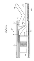
- FIG. 13 is a cross-sectional side view of the distal end section of the ultrasonic treatment apparatus in which only the transducer cover and the outer tube are cut, when the distal end section of the ultrasonic treatment apparatus shown in FIG. 10 is opened;
- FIG. 14 is a perspective view showing a configuration of a first modification of the second embodiment of the distal end section of the ultrasonic treatment apparatus shown in FIG. 10 ;
- FIG. 15 is a second modification of the second embodiment of the distal end section of the ultrasonic treatment apparatus shown in FIG. 10 , and is a cross-sectional side view of a distal end section of an ultrasonic treatment apparatus in which only a transducer cover and an outer tube are cut, when the distal end section of the ultrasonic treatment apparatus is opened;
- FIG. 16 is a side view showing a configuration of a distal end section of an ultrasonic treatment apparatus according to a third embodiment of the present invention, when a portion of an outer tube is truncated;
- FIG. 17 is an E 1 -E 2 cross-sectional view taken along line E 1 -E 2 shown in FIG. 16 ;
- FIG. 18 is an F cross-sectional diagram of FIG. 16 , seep from F arrow direction;
- FIG. 19 is an A 1 -A 2 cross-sectional view of FIG. 16 ;
- FIG. 20 is a B 1 -B 2 cross-sectional view of FIG. 16 ;
- FIG. 21 is a C 1 -C 2 cross-sectional view of FIG. 16 ;
- FIG. 22 is a D 1 -D 2 cross-sectional view of FIG. 16 ;
- FIG. 23 is a G axial cross-sectional view of FIG. 16 , seen from G arrow direction;
- FIG. 24 is a perspective view of a transducer cover shown in FIG. 15 , seen from the distal end direction;
- FIG. 25 is a perspective view of the transducer cover shown in FIG. 15 , seen from the proximal end direction;
- FIG. 26 is a cross-sectional view showing a first modification of the E 1 -E 2 cross section shown in FIG. 17 ;
- FIG. 27 is a D 1 -D 2 cross-sectional view in the modification shown in FIG. 26 ;
- FIG. 28 is a cross-sectional view showing a second modification of the E 1 -E 2 cross section shown in FIG. 17 ;
- FIG. 29 is a D 1 -D 2 cross-sectional view in the modification shown in FIG. 28 .
- FIG. 1 is a schematic diagram showing one of the examples of a configuration of an ultrasonic treatment apparatus used for an endoscope device 1 , according to the present invention.
- the endoscope device 1 includes a video scope 2 connected to a light source and a display unit not shown, an ultrasonic treatment apparatus 3 , and a driving unit 4 that supplies current to the ultrasonic treatment apparatus 3 .
- the ultrasonic treatment apparatus 3 and the driving unit 4 are connected by a signal cable 41 .
- the video scope 2 is provided with an elongated cylinder-shaped insert part 22 that is to be inserted into a patient body and a scope manipulator part 21 that is provided at a proximal end side of the insert part 22 .
- a flexible universal code 21 a connecting the scope manipulator part 21 to the light source and the display unit is connected to a side face of the scope manipulator part 21 .
- a protruding bending manipulator knob 21 b used to manipulate bending of a distal end of the insert part 22 is provided on a side face of the scope manipulator part 21 in which a location of the side face corresponding to the scope manipulator part 21 differs from a location of the side face corresponding to the universal code 21 a .
- a grasp part 21 c is provided in the scope manipulator part 21 to hold and stabilize the video scope 2 by when grasped by an operator.
- a protruding forceps insert opening 21 d used for inserting a forceps which is the ultrasonic treatment apparatus 3 according to the present invention, is provided at an attaching side to which the insert part 22 is attached.
- FIG. 1 shows a condition that the ultrasonic treatment apparatus 3 is inserted into the forceps insert opening 21 d and a manipulator unit 31 that manipulates the ultrasonic treatment apparatus 3 through a flexible sheath 36 is protruded from the forceps insert opening 21 d.
- the insert part 22 to be inserted into the patient body is provided with components such as a rigid distal end part 22 a provided at a distal end of the insert part 22 , a bending part not shown that bends due to manipulation of the scope manipulator part 21 not shown, and a flexible duct that has flexibility, and the components are configured to be aligned.
- FIG. 2 is a perspective view showing one of the examples of a configuration at the distal end part of the insert part shown in FIG. 1 .
- a channel 22 b is formed at the distal end part 22 a of the insert part 22 , and the ultrasonic treatment apparatus 3 is protrudably installed inside the channel 22 b .
- the distal end part 22 a of the insert part 22 is provided with one observation window 22 d that is configured by a observation system lens, and with two illumination windows 22 c that are secured to the distal end and configured by illuminating system lenses.
- a Charge-Coupled Device not shown, which is a solid-state image sensor, is attached to the inmost of the observation window 22 d , and a variety of circuit substrates are secured to a lead provided on back of the CCD. Furthermore, one end of a signal cable that transmits image signals from the circuit substrate is connected to a proximal end of the circuit substrate, and other end of the signal cable is connected to the display unit through the universal code 21 a . Further, one end of an optical guide fiber provided in the insert part 22 is provided at the illumination windows 22 c , and other end thereof is connected to the light source through the universal code 21 a .
- Illumination light emitted from the light source is emitted through the optical guide fiber, and the illumination light is emitted from the illumination windows 22 c of the distal end part 22 a to outside, such as to a part to be treated inside body cavity.
- the observation system lens is configured by, for example, a combination of two lenses (not shown), and reflecting light from the part to be treated inside the body cavity is acquired by the CCD. Then, the image data from the CCD is transmitted as video signals to the signal cable after being subjected to image processing at the circuit substrate. The transmitted video signals are sent through the signal cable to the display unit arranged at the other end of the signal cable, and the image of the part to be treated is displayed. Hence, an operator can observe the part to be treated.
- FIG. 3 is a perspective view showing a configuration of a first embodiment of a distal end section of the ultrasonic treatment apparatus according to the present invention.
- FIG. 4 is a perspective view showing a configuration of one of the examples of the manipulator unit of the ultrasonic treatment apparatus shown in FIG. 1 .
- FIG. 5 is a side view showing a side face of the ultrasonic treatment apparatus when the distal end section of the ultrasonic treatment apparatus is closed.
- FIG. 6 is an A-A cross-sectional view of FIG. 5
- FIG. 7 is a B-B cross-sectional view of FIG. 5 .
- FIG. 8 is a side view showing the side face of the ultrasonic treatment apparatus when the distal end section of the ultrasonic treatment apparatus is opened.
- FIGS. 1 is a perspective view showing a configuration of a first embodiment of a distal end section of the ultrasonic treatment apparatus according to the present invention.
- FIG. 4 is a perspective view showing a configuration of one of the examples of the manipulator
- the ultrasonic treatment apparatus 3 is configured by the manipulator unit 31 , an ultrasonic transducer 32 provided at the distal end section of the ultrasonic treatment apparatus 3 to cause ultrasonic vibration, a cylinder-shaped rigid member 33 that secures the ultrasonic transducer 32 , a gripper 34 that grasps the part to be treated, a manipulator wire 35 that configures the manipulator unit 31 in conjunction with the manipulator unit, and the flexible sheath 36 in which one end thereof is connected to the manipulator unit 31 and other end is connected to the rigid member 33 when the manipulator wire 35 is inserted through the flexible sheath 36 .
- the manipulator unit 31 is provided with a substantially cylinder-shaped manipulator unit main body 31 a , a ring part 31 b provided at one end of the manipulator unit main body 31 a to advance and retreat the manipulator wire 35 , two ways joint 31 c provided at the other end of the manipulator unit main body 31 a to which each of the manipulator wire 35 and the signal cable 41 extending from the driving unit 4 is connected, and a switch 31 d that is provided at a side face of the manipulator unit main body 31 a to control running and stopping of electric signals from the driving unit 4 .
- the signal cable 41 is bent inside the joint 31 c , and the signal cable 41 is inserted into the flexible sheath 36 with the manipulator wire 35 and connected to the ultrasonic transducer 32 provided at the distal end of the insert part 22 . Consequently, the electric signals can be supplied to the ultrasonic transducer 32 .
- the ring part 31 b is configured by a hollow ring 31 b 1 and an insert member 31 b 2 in which one end thereof is connected to the ring 31 b 1 and other end thereof is loosely inserted into the manipulator part main body 31 a and connected to the manipulator wire 35 .
- One end of the manipulator wire 35 inside the flexible sheath 36 is connected to the insert member 31 b 2 and other end thereof is connected to a proximal end part of the gripper 34 .
- the insert member 31 b 2 is inserted into the manipulator unit main body 31 a when an operator inserts his/her finger into the ring 31 b 1 of the ring part 31 b and pushes the ring part 31 b toward the manipulator unit main body 31 a .
- the insert member 31 b 2 protrudes from inside the manipulator unit main body 31 a when the ring part 31 b is shifted away from the manipulator unit main body 31 a . Consequently, the manipulator wire 35 advances and retreats inside the flexible sheath 36 , and the gripper 34 can be opened and closed. Further, the flexible sheath 36 is inserted into the video scope 2 when the manipulator unit main body 31 a is pushed toward the forceps insert opening 21 d , and the flexible sheath 36 protrudes from inside the video scope 2 to outside thereof when the manipulator unit main body 31 a is shifted away from the forceps insert opening 21 d . Consequently, the distal end section of the ultrasonic treatment apparatus 3 protrudes from the distal end of the insert part 22 or the distal end section shifts toward the channel to be housed inside the channel.
- the ultrasonic transducer 32 is provided with an axially elongated cylinder-shaped distal end treatment part 32 a , a horn 32 b that transmits ultrasonic vibration to the distal end treatment part 32 a , a flange 32 c that secures the ultrasonic transducer 32 to the rigid member 33 , a piezoelectric element 32 d that generates ultrasonic vibration, two electrodes 32 e that supply electric signals from the signal cable 41 in which each of the electrodes 32 e is connected to the piezoelectric element 32 d , and a base 32 f.
- the ultrasonic transducer 32 has substantial semi-cylinder shape having an axially provided side plane 32 g , and a cross section of the ultrasonic transducer 32 is D-shaped in radial direction as shown in A-A cross-sectional view of FIG. 6 .
- the flange 32 c has hollow D shape to coincide with the shape of the ultrasonic transducer 32 (see FIG. 3 ).
- the flange 32 c is provided on periphery of the ultrasonic transducer 32 as well as at an equilibrium point of the vibration.
- the flange 32 c is secured to an end part of the transducer insert hole 33 b of the rigid member 33 having a shape identical to the shape of the flange 32 c .
- Oblique lines of the cross section of the ultrasonic transducer 32 is omitted in FIG. 6 to make recognition of the shape easy, and the ultrasonic transducer 32 is shown by two points chained line in FIG. 7 .
- the electric signals from the driving unit 4 described above is supplied to the piezoelectric element 32 d through the signal cable 41 , and the piezoelectric element 32 d generates ultrasonic vibration by receiving the electric signals. Amplitude of the caused ultrasonic vibration is amplified due to the vibration transmitting through the squeeze-shaped horn 32 b , and the ultrasonic vibration is transmitted to the distal end treatment part 32 a.
- the rigid member 33 is, for example, formed by a hollow cylinder-shaped metal member as shown in FIGS. 3 and 7 .
- One end of the rigid member 33 is connected to the flexible sheath 36 , and a manipulator wire insert hole 33 a and the transducer insert hole 33 b is provided at the other end thereof.
- the manipulator wire 35 penetrates the manipulator wire insert hole 33 a , and one end of the manipulator wire 35 is engaged to the gripper 34 by a manipulator pin 34 e .
- the transducer insert hole 33 b is formed to have an axially longer hole compared to the manipulator wire insert hole 33 a , and D shape similar to the shape of the ultrasonic transducer 32 .
- the ultrasonic transducer 32 is inserted into and secured to the transducer insert hole 33 b .
- the signal cable 41 connected to the electrodes 32 e penetrates a diaphragm 33 h , and the signal cable 41 is connected to the outer driving unit 4 with the manipulator wire 35 through the flexible sheath 36 .
- outer diameter of a cylinder section of the rigid member 33 is set to be smaller than inner diameter of the channel 22 b in order to allow the rigid member 33 to be housed inside the channel 22 b and to be protruded from the channel 22 b.
- the gripper 34 includes a link body part 34 c and a box-like grasp member 34 b having an axially elongated groove part 34 a at base therein.
- the groove part 34 a of the grasp member 34 b is formed to contact the distal end treatment part 32 a of the ultrasonic transducer 32 and engages thereto when the grasp member 34 b is closed, as shown in FIG. 5 .
- the link body part 34 c has a D-shaped section so that a complete circle is formed with the rigid member 33 as being a circle missing a piece.
- the link body part 34 c is provided with a supporting pin 34 d that rotatably holds the link body part 34 c so that the link body part 34 c extends along a sidewall 33 c of the rigid member 33 provided on the side of the ultrasonic transducer 32 .
- the link body part 34 c is also provided with a manipulator pin 34 e in a way so that one end of the manipulator wire 35 engages to the link body part 34 c at a sidewall 33 c of the rigid member 33 provided at the side of the ultrasonic transducer 32 .
- a horizontal diameter combining a diameter of the rigid member 33 and a diameter of the link body part 34 c shown in FIG. 6 is substantially equal to the outer diameter of the flexible sheath 36 when the grasp member 34 b is closed. Consequently, the ultrasonic treatment apparatus can be housed inside the channel 22 b and the ultrasonic treatment apparatus can protrude from the channel 22 b . Further, the gripper 34 rotates with respect to the supporting pin 34 d when the grasp member 34 b is opened as shown in FIG. 8 ; therefore, the stroke of the gripper 34 becomes larger than the inner diameter R of the rigid member 33 .
- the insert part 22 of the video scope 2 is inserted into the patient body.
- the body tissue which is the part to be treated, is recognized by observing inside the patient body through the observation window 22 d while illuminating the region by emitted illumination light from the illumination windows 22 c .
- the ultrasonic treatment apparatus 3 is inserted into the channel 22 b from the forceps insert opening 21 d after specifying the part to be treated while having the gripper 34 closed.
- the insert part 22 of the video scope 2 can be inserted into the patient body when the distal end of the ultrasonic treatment apparatus 3 is housed in the channel 22 b as shown in FIG. 2 .
- the flexible sheath 36 is shifted inside the insert part 22 toward the distal end direction by the operator pushing the manipulator unit main body 31 a of the manipulator unit 31 toward the video scope 2 . Consequently, the distal end of the ultrasonic treatment apparatus 3 protrudes into the patient body.
- the flexible sheath 36 shifts toward the distal end direction thereof since the manipulator wire 35 is linked up with the ring part 31 b .
- the gripper 34 opens when the grasp member 34 b of the gripper 34 is rotated toward H direction of an arrow shown in FIG. 8 with respect to the supporting pin 34 d that is a fulcrum.
- the insert part 22 is manipulated to locate the body tissue in between the grasp member 34 b of the gripper 34 and the distal end treatment part 32 a of the ultrasonic transducer 32 .
- the grasp member 34 b is rotated toward the L direction of an arrow with respect to the supporting pin 34 d that is the fulcrum, when the operator shifts the ring part 31 b away from the manipulator unit main body 31 a . Consequently, spacing between the distal end treatment part 32 a and the grasp member 34 b narrows, and the body tissue is grasped.
- ultrasonic vibration due to the ultrasonic transducer 32 is caused when a switch 31 d of the manipulator unit 31 is turned on to supply the electric signals from the driving unit to the ultrasonic transducer 32 .
- the amplitude of the ultrasonic vibration is amplified by the horn 32 b , and the ultrasonic vibration is transmitted to the distal end treatment part 32 a .
- the vibration of the distal end treatment part 32 a is initiated, the body tissue contacting the distal end treatment unit 32 a is cut by the ultrasonic vibration as well as the part to be treated is coagulated by frictional heat.
- the horn of the ultrasonic transducer, the piezoelectric element, and the base have substantially semi-cylindrical shape having axially provided side plane, and the rigid member has cylindrical shape with D-shaped partially circular cross section, in order to obtain a space for providing the link body part of the gripper on the side of the ultrasonic transducer. Consequently, the link body used to open and close the gripper is effectively housed inside the sheath.
- the grasping of the part to be treated inside the patient body is allowed by placing the part to be treated in between the gripper and the treatment part. Therefore, overall size of the ultrasonic treatment apparatus can be downsized as well as large stroke for opening and closing the gripper can be obtained, and the surgical operation of the body tissue inside the patient body can be easily performed by ultrasonic vibration.
- FIG. 9 is a perspective view showing a configuration of a modification of the first embodiment of the distal end section of the ultrasonic treatment apparatus shown in FIG. 3 .
- the configuration in FIG. 9 differs from the configuration in FIG. 3 only by the configurations in which the distal end treatment part 32 a of the ultrasonic transducer 32 is provided in eccentric position with respect to a central axis of the flexible sheath 32 and the distal end treatment part 32 a is arranged at lower part of the ultrasonic transducer 32 .
- the grasp member 34 b of the gripper 34 is in eccentric position with respect to the central axis of the flexible sheath 36 .
- the distal end treatment part 32 a and the grasp member 34 b are arranged so that the groove part 34 a of the grasp member 34 b contacts the distal end treatment part 32 a of the ultrasonic transducer 32 and engages thereto, when the distal end treatment part 32 a is closed. While shifting the manipulator wire for the same amount in the modification and the first embodiment, larger stroke of the opening and closing of the gripper 34 can be obtained in the modification compared to the stroke in the first embodiment because the grasp member 34 b is provided downwards with respect to the center of the flexible sheath. Consequently, the ultrasonic treatment apparatus according to the present invention can be used for treating large body tissue such as polyps inside the patient.
- the horn, the piezoelectric element, and the base of the ultrasonic transducer have the substantial semi-cylindrical shape on the axially provided side plane in the present modification.
- the rigid member has a cylindrical shape with a D-shaped partially circular section, and the distal end treatment part of the ultrasonic transducer is provided off-centered below the central axis of the inner periphery of the flexible sheath. Consequently, the link body that opens and closes the gripper can be effectively housed inside the sheath, and larger stroke for opening and closing the gripper is obtained. Therefore, treatment of the body tissue inside the patient can be more easily performed by ultrasonic vibration.
- FIG. 10 is a perspective view showing a configuration of the distal end section of the ultrasonic treatment apparatus according to a second embodiment of the present invention.
- FIG. 11 is a cross-sectional side view of the distal end section of the ultrasonic treatment apparatus in which only a transducer cover and an outer tube are cut, when the distal end section of the ultrasonic treatment apparatus shown in FIG. 10 is closed.
- FIG. 12 is a C-C cross-sectional view of FIG. 11 .
- FIG. 13 is a cross-sectional side view of the distal end section of the ultrasonic treatment apparatus in which only the transducer cover and the outer tube are cut, when the distal end section of the ultrasonic treatment apparatus shown in FIG. 10 is opened. In the perspective view of FIG.
- the ultrasonic transducer 32 is provided with the distal end treatment part 32 a , the horn 32 b , the flange 32 c , the piezoelectric element 32 d , the electrode 32 e , and the base 32 f , as similar to the first embodiment.
- the distal end treatment part 32 a is off-centered downwards with respect to the central axis of the flexible sheath 36 , and arranged at lower part of the ultrasonic transducer 32 .
- the horn 32 b has downwards squeezing shape toward the lower part of the ultrasonic transducer 32 .
- the piezoelectric element 32 d , the base 32 f , and a portion of the horn 32 b have cylindrical shape.
- the flange 32 c has hollow circular ring shape in order to coincide with the shape of the ultrasonic transducer 32 .
- the flange 32 c is provided around the periphery of the ultrasonic transducer 32 as well as provided at the equilibrium point of the vibration, and the flange 32 c is secured to an end part of the transducer insert hole 33 f of a transducer cover 33 d having identical shape to the flange 32 c as shown in FIG. 11 .
- the rigid member 33 has hollow cylindrical shape.
- the rigid member 33 is configured by the transducer cover 33 d in which the ultrasonic transducer 32 is inserted and secured and an outer tube 33 e that covers the transducer cover 33 d , and one end of the outer tube 33 e is connected to the flexible sheath 36 .
- FIG. 12 although most of an inner diameter of the outer tube 33 e contacts with an outer diameter of the transducer cover 33 d , there is a space in which upper portion of the outer tube 33 e does not touch the transducer cover 33 d .
- a manipulator wire insert hole 33 g which is an insert hole of the manipulator wire 35 , is formed at the space.
- a portion of the cylinder at other end of the outer tube 33 e is axially cut so that a coating member 33 e 1 having C-shaped cross section in radial direction is formed as shown in FIG. 12 .
- An outer diameter of the outer tube 33 e is formed to be smaller than the inner diameter of the channel 22 b so that the outer tube 33 e can be housed inside the channel 22 and the outer tube 33 e can be protruded from the channel 22 b.
- the gripper 34 is configured by the rectangular solid grasp part 34 b that has the groove part 34 a at the bottom face therein, and the link body part 34 c having two ear-shaped manipulator wire securing members 34 c 1 and 34 c 2 that are to be connected at a grasp member 34 b side.
- the groove part 34 a of the grasp member 34 b is formed to contact with the distal end treatment part 32 a of the ultrasonic transducer 32 and engages thereto when the grasp member 34 b is closed, in the present embodiment.
- the link body part 34 c is provided in front of the ultrasonic transducer 32 and at a space located above the distal end treatment part 32 a .
- the space is caused due to downward off-centering of the distal end treatment part 32 a and the horn 32 b of the ultrasonic transducer 32 .
- the link body part 34 c is provided with the supporting pin 34 d that rotatably holds the link body part 34 c , and manipulator pins 34 e 1 and 34 e 2 that are used to engage each end of the two-forked manipulator wire 35 to the manipulator wire securing member 34 c 1 and 34 c 2 , in the inner periphery face of the coating member 33 e 1 .
- the link body part 34 c is configured by lengths and widths fittable in the diameter of the outer tube 33 e when the grasp member 34 b is closed. Consequently, the ultrasonic treatment apparatus can be housed inside the channel 22 b and the ultrasonic treatment apparatus can be protruded from the channel 22 b . Further, as shown in FIG. 13 , the gripper 34 can have larger stroke than the inner diameter r of the outer tube 33 e when the gripper 34 rotates with respect to the supporting pin 34 d that is a fulcrum.
- the ultrasonic treatment apparatus of the second embodiment behaves in a way similar to the ultrasonic treatment apparatus of the first embodiment. That is to say, when the ring part 31 b is pushed into the manipulator part main body 31 a , the manipulator wire 35 is linked to the motion and the manipulator wire 35 is shifted toward the distal end direction of the flexible sheath 36 . Then, the gripper 34 is opened since the grasp member 34 b of the gripper 34 is rotated toward the H direction of the arrow with respect to the supporting pin 34 d that is the fulcrum, as shown in FIG. 13 .
- the grasp member 34 b is rotated toward the L direction of the arrow by shifting the ring part 31 b away from the manipulator part main body 31 a with respect to the supporting pin 34 d that is the fulcrum.
- the body tissue is grasped and treatment of the body tissue can be performed since the spacing in between the distal end treatment part 32 a and the grasp member 34 b becomes narrower.
- the distal end treatment part and the horn of the ultrasonic transducer are provided off-centered downwards with respect to the central axis of the inner periphery of the flexible sheath as well as providing the link body part at the space caused by the off-centering described above located in front of the ultrasonic transducer and above the distal end treatment part. Consequently, treatment of the body tissue inside the patient body can be performed more easily by ultrasonic vibration since the link body used to open and close the gripper is effectively housed inside the sheath and large stroke of the opening and closing of the gripper is obtained.
- FIG. 14 is a perspective view showing a configuration of a first modification of the second embodiment of the distal end section of the ultrasonic treatment apparatus shown in FIG. 10 .
- the distal end treatment part 32 a of the ultrasonic transducer 32 is provided at the center of the flexible sheath 36
- the grasp member 34 b of the gripper 34 is provided at the center of the flexible sheath 36 , as similar to the first embodiment.
- overall size of the ultrasonic treatment apparatus can be miniaturized and large stroke for opening and closing the gripper can be obtained since the link body part is provided at the space in front of the ultrasonic transducer to effectively house the link body used to open and close the grasp part inside the sheath. As a result, treatment on the body tissue inside the patient body is easily performed by ultrasonic vibration.
- FIG. 15 shows a second modification of the second embodiment of the distal end section of the ultrasonic treatment apparatus shown in FIG. 10 .
- FIG. 15 shows a side view of the distal end section of the ultrasonic treatment apparatus in which the transducer cover and the outer tube are cut, when the distal end section of the ultrasonic treatment apparatus is opened.
- the distal end treatment part 32 a might bend down by load thereof when the grasp member 34 b of the gripper 34 is closed to grasp the body tissue in between the grasp member 34 b and the distal end treatment part 32 a of the ultrasonic transducer 32 .
- the bending lowers transmission efficiency of ultrasonic vibration transmitted to the distal end treatment part 32 a.
- the bending of the distal end treatment part 32 a is prevented by providing a treatment part receiver 32 d 1 at the distal end section of the transducer cover 33 d to support the distal end treatment part 32 a from below, as shown in FIG. 15 .
- the second modification thereof can prevent the bending down of the distal end treatment part due to the load since the treatment part receiver that supports the distal end treatment part from below is provided.
- the link body part 34 c is supported by the supporting pin 34 d at one position of the rigid member 33 in the embodiment described above. Consequently, smooth opening and closing of the gripper 34 and accurate grasping of the body tissue in between the distal end treatment part 32 a and the grasp member 34 b may not be performed since the entire gripper 34 wobbles while opening and closing the grasp member 34 b . Therefore, an ultrasonic treatment apparatus is provided in a third embodiment to alleviate above inconvenience.
- FIG. 16 is a side view showing a configuration of the distal end section of the ultrasonic treatment apparatus according to the third embodiment of the present invention, when a portion of an outer tube is truncated.
- FIG. 17 is an E 1 -E 2 cross-sectional view taken along line E 1 -E 2 shown in FIG. 16 .
- FIG. 18 is an F cross-sectional diagram of FIG. 16 , seen from F arrow direction.
- FIG. 19 is an A 1 -A 2 cross-sectional view of FIG. 16
- FIG. 20 is a B 1 -B 2 cross-sectional view of FIG. 16
- FIG. 21 is a C 1 -C 2 cross-sectional view of FIG. 16
- FIG. 22 is a D 1 -D 2 cross-sectional view of FIG. 16 .
- FIG. 23 is a G cross-sectional view of FIG. 16 , seen from G arrow direction.
- the ultrasonic transducer of the present embodiment has cylindrical shape and provided with the distal end treatment part 32 a , the horn 32 b , the piezoelectric element 32 d , the electrode 32 e , and the base 32 f , as similar to the ultrasonic transducer of the second embodiment.
- the ultrasonic transducer of the present embodiment differs from those in the second embodiment by configurations that the distal end treatment part 32 a is provided at the center of the flexible sheath and the flange is not provided in the present embodiment.
- a boss (flange) 32 i is provided at the periphery of the ultrasonic transducer 32 and at the equilibrium position of the vibration.
- the boss 32 i is configured to have a shape identical to the inner periphery face of the transducer cover 33 d , and the boss 32 i touches and is secured to the inner periphery of the transducer cover 33 d .
- the ultrasonic transducer 32 is configured by four piezoelectric elements 32 d , and each of the piezoelectric elements 32 d is connected to other piezoelectric element 32 d that is not adjoined thereto through a connecting member 32 h . Further, the piezoelectric elements 32 d are connected to the signal cable 41 through positive or negative electrode 32 e.
- the rigid member 33 is configured by the transducer cover 33 d to which the ultrasonic transducer 32 is inserted and secured, and the outer tube 33 e that is formed to cover the transducer cover 33 d . Further, one end (proximal end) of the transducer cover 33 d is connected to the flexible sheath 36 .
- FIG. 24 is a perspective view of the transducer cover 33 d shown in FIG. 15 , seen from distal end direction
- FIG. 25 is a perspective view, seen from the proximal end direction.
- the transducer cover 33 d has substantially cylindrical shape, and also has a distal end part 33 d 1 , a center part 33 d 2 , and a proximal end part 33 d 3 in which each of inner shape of the parts differ from one another.
- the distal end part 33 d 1 has hollow shape enabling the ultrasonic transducer 32 to be housed therein, and both side faces are chamfered to form two attaching faces 33 d 4 .
- Two engaging holes 33 d 5 opposing to each other are formed on the attaching faces 33 d 4 to engage with a pair of supporting pins.
- the center part 33 d 2 is hollowed out in vertical direction to form a space 33 d 6 , and a U-shaped cross section of a groove 33 d 7 is formed in longitudinal direction.
- the distal end section (the distal end part 33 d 1 side) of the groove 33 d 7 is formed in R shape. If the distal end of the groove 33 d 7 would be formed with an edge of 90 degrees in angle, there would be a possibility that the manipulator wire 35 might be caught at the entrance. Hence, the edge is formed to have R shape to prevent the problem described above.
- the edge of the distal end section to R shape can be formed to have, for example, more than or equal to 100 degrees in inclination in order to prevent the manipulator wire 35 to be caught.
- a distal end side in longitudinal direction of the center part 33 d 2 is communicatively connected to the hollow section of the distal end part 33 d 1 so that the ultrasonic transducer 32 can be housed therein, and a diaphragm 33 d 8 is formed at a proximal end side of the center part 33 d 2 .
- a side hole 33 d 9 that penetrates horizontally is formed at the proximal end part 33 d 3 , and an end part in longitudinal direction of the side hole 33 d 9 is formed to be R-shaped as well as the side hole 33 d 9 is communicatively connected to the groove 33 d 7 of the center part 33 d 2 .
- a connecting hole 33 d 10 that communicatively connected to the connected flexible sheath 36 is formed at a proximal end part of the side hole 33 d 9 . Consequently, the manipulator wire 35 that protrudes from the flexible sheath 36 runs through the connecting hole 33 d 10 and spread in radial direction of the transducer cover 33 d at the side hole 33 d 9 .
- the manipulator wires 35 run through the grooves 33 d 7 of the center part 33 d 2 to reach the attaching faces 33 d 4 of the distal end part 33 d 1 .
- a communicative connecting hole 33 d 11 that communicatively connected to the space 33 d 6 of the center part 33 d 2 is formed below the connecting hole 33 d 10 , and the signal cable 41 from the driving unit 4 is inserted into the communicatively connecting hole 33 d 11 so that the signal cable 41 can reach the space 33 d 6 of the center part 33 d 2 .
- Substantially half of the transducer cover 33 d is inserted into the outer tube 33 e , and secured therein by, for example, a screw.
- the gripper 34 has axially slender groove part 34 a at the bottom face, and the gripper 34 is configured by the grasp member 34 b that has triangular shape on the side thereof and the link body part 34 c that is provided on a backside of the grasp member 34 b . Further, the gripper 34 is formed so that the groove 34 a contacts the distal end treatment part 32 a of the ultrasonic transducer 32 and engages thereto when the grasp member 34 b is closed.
- two of the cross-sectional shapes of the link body parts 34 c are formed in D shapes that cover the outer periphery of the attaching face 33 d 4 of the transducer cover 33 d .
- the link body part 34 c has the supporting pins 34 d that engage to engaging holes 33 d 5 provided on the attaching face 33 d 4 .
- the link body part 34 c has the manipulator pins 34 e by which each end of the manipulator wire 35 is engaged to the link body part 34 c .
- the link body part 34 c is provided with respect to the supporting pins 34 d at two points so that the link body part 34 c rotates along the attaching face 33 d 4 .
- the supporting pins 34 d which are the fulcrums for opening and closing of the grasp member 34 b , is preferably provided above the manipulator pins 34 e , which are points of action. Further, the supporting pins 34 e are preferably arranged above the central axis of the transducer cover 33 d in longitudinal direction, and the manipulator pins 34 e are preferably arranged below the central axis thereof. Consequently, grasp force necessary to accurately grasp the body tissue is obtained when the manipulator wire 35 is pulled toward the flexible sheath 36 to close the gripper 34 . Further, the gripper 34 rotates with respect to the fulcrum, which is the supporting pin 34 d , when the manipulator wire 35 is pushed away from the flexible sheath 36 . Consequently, the gripper 34 opens easily, and the body tissue can be released easily.
- the boss 32 i that has a function of the flange of the ultrasonic transducer 32 is provided at the positions of two engaging holes 33 d 5 of the distal end part 33 d 1 , and the bosses 32 i are secured to the distal end part 33 d 1 of the transducer cover 33 d by fitting with the two supporting pins 34 d .
- the supporting pins 34 d has a function of supporting means to rotatably supports the gripper 34 , and a function of securing means to secure the ultrasonic transducer 32 to the transducer cover 33 d . Consequently, the ultrasonic transducer can be secured without using a flange or a securing screw.
- a configuration of the supporting pin 34 d according to the present invention is not limited to the above embodiments, and the supporting pin 34 d can penetrate through the flange 32 i as shown in FIGS. 26 and 27 . Further, a small boss 32 k can be provided on the flange 32 i to replace the supporting pin 34 d , as shown in FIGS. 28 and 29 .
- the outer diameter of the outer tube 33 e is set to be smaller than the inner diameter of the cannel 22 b of the ultrasonic treatment apparatus.
- Combined diameter of the outer diameter of the transducer cover 33 d in horizontal direction and the thickness of the link body parts 34 c is equal to the outer diameter of the outer tube 33 e , and substantially equal to the outer diameter of the transducer cover 33 d in longitudinal direction as shown in FIG. 22 . Consequently, the outer tube 33 e and the transducer cover 33 d can be housed inside the channel 22 b of the ultrasonic treatment apparatus, and the outer tube 33 e and the transducer cover 33 d can be protruded from the channel 22 b .
- the ultrasonic treatment apparatus of the third embodiment can accurately grasp the body tissue to perform treatment.
- the ultrasonic treatment apparatus of the present embodiment can obtain the similar effect to the ultrasonic treatment apparatus of the first and the second embodiments.
- the transducer cover rotatably supports the gripper of the ultrasonic treatment apparatus of the present embodiment by the pair of fulcrums, which is made by the two supporting pins; therefore, the entire gripper does not wobble when the grasp member is opened and closed.
- smooth opening and closing of the grasp member and accurate grasping of the body tissue in between the distal end treatment part and the grasp member can be performed.
- the rigid member of the distal end of the ultrasonic treatment apparatus has dual structure configured by the outer tube and the transducer cover, and the groove is provided to house the manipulator wire in between the outer tube and the transducer cover. Consequently, there is less exposure of the manipulator wire, and motion of the manipulator wire is confined; therefore, the opening and closing of the gripper can be accurately performed since the manipulator wire does not bend even if the rigid portion of the ultrasonic transducer becomes longer.
- the hole provided on the transducer cover to be used for the manipulator wire and the hole to be used for the signal cable are provided so that the passages of the manipulator wire differs from the passage of the signal cable to prevent the interference therebetween, in the present embodiment. Further, water tightness of the ultrasonic transducer can be obtained.
Abstract
Description
Claims (10)
Applications Claiming Priority (6)
| Application Number | Priority Date | Filing Date | Title |
|---|---|---|---|
| JP2005-005542 | 2004-01-13 | ||
| JP2004-005542 | 2004-01-13 | ||
| JP2004005542 | 2004-01-13 | ||
| JP2004121424A JP4262631B2 (en) | 2004-01-13 | 2004-04-16 | Ultrasonic treatment device |
| JP2004-121424 | 2004-04-16 | ||
| PCT/JP2004/019027 WO2005067805A1 (en) | 2004-01-13 | 2004-12-20 | Ultrasonic treating device |
Related Parent Applications (1)
| Application Number | Title | Priority Date | Filing Date |
|---|---|---|---|
| PCT/JP2004/019027 Continuation WO2005067805A1 (en) | 2004-01-13 | 2004-12-20 | Ultrasonic treating device |
Publications (2)
| Publication Number | Publication Date |
|---|---|
| US20060264750A1 US20060264750A1 (en) | 2006-11-23 |
| US7837699B2 true US7837699B2 (en) | 2010-11-23 |
Family
ID=34797726
Family Applications (1)
| Application Number | Title | Priority Date | Filing Date |
|---|---|---|---|
| US11/485,561 Expired - Fee Related US7837699B2 (en) | 2004-01-13 | 2006-07-12 | Ultrasonic treatment apparatus |
Country Status (4)
| Country | Link |
|---|---|
| US (1) | US7837699B2 (en) |
| EP (1) | EP1704824B1 (en) |
| JP (1) | JP4262631B2 (en) |
| WO (1) | WO2005067805A1 (en) |
Cited By (148)
| Publication number | Priority date | Publication date | Assignee | Title |
|---|---|---|---|---|
| US8419759B2 (en) | 2010-02-11 | 2013-04-16 | Ethicon Endo-Surgery, Inc. | Ultrasonic surgical instrument with comb-like tissue trimming device |
| US8461744B2 (en) | 2009-07-15 | 2013-06-11 | Ethicon Endo-Surgery, Inc. | Rotating transducer mount for ultrasonic surgical instruments |
| US8469981B2 (en) | 2010-02-11 | 2013-06-25 | Ethicon Endo-Surgery, Inc. | Rotatable cutting implement arrangements for ultrasonic surgical instruments |
| US8486096B2 (en) | 2010-02-11 | 2013-07-16 | Ethicon Endo-Surgery, Inc. | Dual purpose surgical instrument for cutting and coagulating tissue |
| US8512365B2 (en) | 2007-07-31 | 2013-08-20 | Ethicon Endo-Surgery, Inc. | Surgical instruments |
| US8523889B2 (en) | 2007-07-27 | 2013-09-03 | Ethicon Endo-Surgery, Inc. | Ultrasonic end effectors with increased active length |
| US8531064B2 (en) | 2010-02-11 | 2013-09-10 | Ethicon Endo-Surgery, Inc. | Ultrasonically powered surgical instruments with rotating cutting implement |
| US8546999B2 (en) * | 2009-06-24 | 2013-10-01 | Ethicon Endo-Surgery, Inc. | Housing arrangements for ultrasonic surgical instruments |
| US8546996B2 (en) | 2008-08-06 | 2013-10-01 | Ethicon Endo-Surgery, Inc. | Devices and techniques for cutting and coagulating tissue |
| US8579928B2 (en) | 2010-02-11 | 2013-11-12 | Ethicon Endo-Surgery, Inc. | Outer sheath and blade arrangements for ultrasonic surgical instruments |
| US8591536B2 (en) | 2007-11-30 | 2013-11-26 | Ethicon Endo-Surgery, Inc. | Ultrasonic surgical instrument blades |
| US8623027B2 (en) | 2007-10-05 | 2014-01-07 | Ethicon Endo-Surgery, Inc. | Ergonomic surgical instruments |
| US8663220B2 (en) | 2009-07-15 | 2014-03-04 | Ethicon Endo-Surgery, Inc. | Ultrasonic surgical instruments |
| US8704425B2 (en) | 2008-08-06 | 2014-04-22 | Ethicon Endo-Surgery, Inc. | Ultrasonic device for cutting and coagulating with stepped output |
| US8709031B2 (en) | 2007-07-31 | 2014-04-29 | Ethicon Endo-Surgery, Inc. | Methods for driving an ultrasonic surgical instrument with modulator |
| US8808319B2 (en) | 2007-07-27 | 2014-08-19 | Ethicon Endo-Surgery, Inc. | Surgical instruments |
| US8900259B2 (en) | 2007-03-22 | 2014-12-02 | Ethicon Endo-Surgery, Inc. | Surgical instruments |
| US8951248B2 (en) | 2009-10-09 | 2015-02-10 | Ethicon Endo-Surgery, Inc. | Surgical generator for ultrasonic and electrosurgical devices |
| US8951272B2 (en) | 2010-02-11 | 2015-02-10 | Ethicon Endo-Surgery, Inc. | Seal arrangements for ultrasonically powered surgical instruments |
| US8961547B2 (en) | 2010-02-11 | 2015-02-24 | Ethicon Endo-Surgery, Inc. | Ultrasonic surgical instruments with moving cutting implement |
| US9017326B2 (en) | 2009-07-15 | 2015-04-28 | Ethicon Endo-Surgery, Inc. | Impedance monitoring apparatus, system, and method for ultrasonic surgical instruments |
| US9044261B2 (en) | 2007-07-31 | 2015-06-02 | Ethicon Endo-Surgery, Inc. | Temperature controlled ultrasonic surgical instruments |
| US9050124B2 (en) | 2007-03-22 | 2015-06-09 | Ethicon Endo-Surgery, Inc. | Ultrasonic surgical instrument and cartilage and bone shaping blades therefor |
| US9095367B2 (en) | 2012-10-22 | 2015-08-04 | Ethicon Endo-Surgery, Inc. | Flexible harmonic waveguides/blades for surgical instruments |
| US9168054B2 (en) | 2009-10-09 | 2015-10-27 | Ethicon Endo-Surgery, Inc. | Surgical generator for ultrasonic and electrosurgical devices |
| US9198714B2 (en) | 2012-06-29 | 2015-12-01 | Ethicon Endo-Surgery, Inc. | Haptic feedback devices for surgical robot |
| US9226767B2 (en) | 2012-06-29 | 2016-01-05 | Ethicon Endo-Surgery, Inc. | Closed feedback control for electrosurgical device |
| US9226766B2 (en) | 2012-04-09 | 2016-01-05 | Ethicon Endo-Surgery, Inc. | Serial communication protocol for medical device |
| US9232979B2 (en) | 2012-02-10 | 2016-01-12 | Ethicon Endo-Surgery, Inc. | Robotically controlled surgical instrument |
| US9237921B2 (en) | 2012-04-09 | 2016-01-19 | Ethicon Endo-Surgery, Inc. | Devices and techniques for cutting and coagulating tissue |
| US9241731B2 (en) | 2012-04-09 | 2016-01-26 | Ethicon Endo-Surgery, Inc. | Rotatable electrical connection for ultrasonic surgical instruments |
| US9241728B2 (en) | 2013-03-15 | 2016-01-26 | Ethicon Endo-Surgery, Inc. | Surgical instrument with multiple clamping mechanisms |
| US9259234B2 (en) | 2010-02-11 | 2016-02-16 | Ethicon Endo-Surgery, Llc | Ultrasonic surgical instruments with rotatable blade and hollow sheath arrangements |
| US9283045B2 (en) | 2012-06-29 | 2016-03-15 | Ethicon Endo-Surgery, Llc | Surgical instruments with fluid management system |
| US9326788B2 (en) | 2012-06-29 | 2016-05-03 | Ethicon Endo-Surgery, Llc | Lockout mechanism for use with robotic electrosurgical device |
| US9351754B2 (en) | 2012-06-29 | 2016-05-31 | Ethicon Endo-Surgery, Llc | Ultrasonic surgical instruments with distally positioned jaw assemblies |
| US9393037B2 (en) | 2012-06-29 | 2016-07-19 | Ethicon Endo-Surgery, Llc | Surgical instruments with articulating shafts |
| US9408622B2 (en) | 2012-06-29 | 2016-08-09 | Ethicon Endo-Surgery, Llc | Surgical instruments with articulating shafts |
| US9439668B2 (en) | 2012-04-09 | 2016-09-13 | Ethicon Endo-Surgery, Llc | Switch arrangements for ultrasonic surgical instruments |
| US9439669B2 (en) | 2007-07-31 | 2016-09-13 | Ethicon Endo-Surgery, Llc | Ultrasonic surgical instruments |
| US9504483B2 (en) | 2007-03-22 | 2016-11-29 | Ethicon Endo-Surgery, Llc | Surgical instruments |
| US9636135B2 (en) | 2007-07-27 | 2017-05-02 | Ethicon Endo-Surgery, Llc | Ultrasonic surgical instruments |
| US9700339B2 (en) | 2009-05-20 | 2017-07-11 | Ethicon Endo-Surgery, Inc. | Coupling arrangements and methods for attaching tools to ultrasonic surgical instruments |
| US9707027B2 (en) | 2010-05-21 | 2017-07-18 | Ethicon Endo-Surgery, Llc | Medical device |
| US9724118B2 (en) | 2012-04-09 | 2017-08-08 | Ethicon Endo-Surgery, Llc | Techniques for cutting and coagulating tissue for ultrasonic surgical instruments |
| US9820768B2 (en) | 2012-06-29 | 2017-11-21 | Ethicon Llc | Ultrasonic surgical instruments with control mechanisms |
| US9883884B2 (en) | 2007-03-22 | 2018-02-06 | Ethicon Llc | Ultrasonic surgical instruments |
| US10010339B2 (en) | 2007-11-30 | 2018-07-03 | Ethicon Llc | Ultrasonic surgical blades |
| US10034684B2 (en) | 2015-06-15 | 2018-07-31 | Ethicon Llc | Apparatus and method for dissecting and coagulating tissue |
| US10034704B2 (en) | 2015-06-30 | 2018-07-31 | Ethicon Llc | Surgical instrument with user adaptable algorithms |
| US10154852B2 (en) | 2015-07-01 | 2018-12-18 | Ethicon Llc | Ultrasonic surgical blade with improved cutting and coagulation features |
| US10179022B2 (en) | 2015-12-30 | 2019-01-15 | Ethicon Llc | Jaw position impedance limiter for electrosurgical instrument |
| US10194973B2 (en) | 2015-09-30 | 2019-02-05 | Ethicon Llc | Generator for digitally generating electrical signal waveforms for electrosurgical and ultrasonic surgical instruments |
| US10201365B2 (en) | 2012-10-22 | 2019-02-12 | Ethicon Llc | Surgeon feedback sensing and display methods |
| US10226273B2 (en) | 2013-03-14 | 2019-03-12 | Ethicon Llc | Mechanical fasteners for use with surgical energy devices |
| US10245064B2 (en) | 2016-07-12 | 2019-04-02 | Ethicon Llc | Ultrasonic surgical instrument with piezoelectric central lumen transducer |
| US10251664B2 (en) | 2016-01-15 | 2019-04-09 | Ethicon Llc | Modular battery powered handheld surgical instrument with multi-function motor via shifting gear assembly |
| USD847990S1 (en) | 2016-08-16 | 2019-05-07 | Ethicon Llc | Surgical instrument |
| US10278721B2 (en) | 2010-07-22 | 2019-05-07 | Ethicon Llc | Electrosurgical instrument with separate closure and cutting members |
| US10285723B2 (en) | 2016-08-09 | 2019-05-14 | Ethicon Llc | Ultrasonic surgical blade with improved heel portion |
| US10285724B2 (en) | 2014-07-31 | 2019-05-14 | Ethicon Llc | Actuation mechanisms and load adjustment assemblies for surgical instruments |
| US10321950B2 (en) | 2015-03-17 | 2019-06-18 | Ethicon Llc | Managing tissue treatment |
| US10342602B2 (en) | 2015-03-17 | 2019-07-09 | Ethicon Llc | Managing tissue treatment |
| US10349999B2 (en) | 2014-03-31 | 2019-07-16 | Ethicon Llc | Controlling impedance rise in electrosurgical medical devices |
| US10357303B2 (en) | 2015-06-30 | 2019-07-23 | Ethicon Llc | Translatable outer tube for sealing using shielded lap chole dissector |
| US10376305B2 (en) | 2016-08-05 | 2019-08-13 | Ethicon Llc | Methods and systems for advanced harmonic energy |
| US10420580B2 (en) | 2016-08-25 | 2019-09-24 | Ethicon Llc | Ultrasonic transducer for surgical instrument |
| US10433900B2 (en) | 2011-07-22 | 2019-10-08 | Ethicon Llc | Surgical instruments for tensioning tissue |
| US10441345B2 (en) | 2009-10-09 | 2019-10-15 | Ethicon Llc | Surgical generator for ultrasonic and electrosurgical devices |
| US10456193B2 (en) | 2016-05-03 | 2019-10-29 | Ethicon Llc | Medical device with a bilateral jaw configuration for nerve stimulation |
| US10463421B2 (en) | 2014-03-27 | 2019-11-05 | Ethicon Llc | Two stage trigger, clamp and cut bipolar vessel sealer |
| US10485607B2 (en) | 2016-04-29 | 2019-11-26 | Ethicon Llc | Jaw structure with distal closure for electrosurgical instruments |
| US10524854B2 (en) | 2010-07-23 | 2020-01-07 | Ethicon Llc | Surgical instrument |
| US10537352B2 (en) | 2004-10-08 | 2020-01-21 | Ethicon Llc | Tissue pads for use with surgical instruments |
| US10555769B2 (en) | 2016-02-22 | 2020-02-11 | Ethicon Llc | Flexible circuits for electrosurgical instrument |
| US10575892B2 (en) | 2015-12-31 | 2020-03-03 | Ethicon Llc | Adapter for electrical surgical instruments |
| US10595930B2 (en) | 2015-10-16 | 2020-03-24 | Ethicon Llc | Electrode wiping surgical device |
| US10595929B2 (en) | 2015-03-24 | 2020-03-24 | Ethicon Llc | Surgical instruments with firing system overload protection mechanisms |
| US10603064B2 (en) | 2016-11-28 | 2020-03-31 | Ethicon Llc | Ultrasonic transducer |
| US10603117B2 (en) | 2017-06-28 | 2020-03-31 | Ethicon Llc | Articulation state detection mechanisms |
| US10639092B2 (en) | 2014-12-08 | 2020-05-05 | Ethicon Llc | Electrode configurations for surgical instruments |
| US10646269B2 (en) | 2016-04-29 | 2020-05-12 | Ethicon Llc | Non-linear jaw gap for electrosurgical instruments |
| USRE47996E1 (en) | 2009-10-09 | 2020-05-19 | Ethicon Llc | Surgical generator for ultrasonic and electrosurgical devices |
| US20200155190A1 (en) * | 2017-06-30 | 2020-05-21 | Enlightenvue Llc | Endoscopy systems and methods of use thereof |
| US10702329B2 (en) | 2016-04-29 | 2020-07-07 | Ethicon Llc | Jaw structure with distal post for electrosurgical instruments |
| US10716615B2 (en) | 2016-01-15 | 2020-07-21 | Ethicon Llc | Modular battery powered handheld surgical instrument with curved end effectors having asymmetric engagement between jaw and blade |
| US10751109B2 (en) | 2014-12-22 | 2020-08-25 | Ethicon Llc | High power battery powered RF amplifier topology |
| US10751117B2 (en) | 2016-09-23 | 2020-08-25 | Ethicon Llc | Electrosurgical instrument with fluid diverter |
| US10765470B2 (en) | 2015-06-30 | 2020-09-08 | Ethicon Llc | Surgical system with user adaptable techniques employing simultaneous energy modalities based on tissue parameters |
| US10779845B2 (en) | 2012-06-29 | 2020-09-22 | Ethicon Llc | Ultrasonic surgical instruments with distally positioned transducers |
| US10779879B2 (en) | 2014-03-18 | 2020-09-22 | Ethicon Llc | Detecting short circuits in electrosurgical medical devices |
| US10779848B2 (en) | 2006-01-20 | 2020-09-22 | Ethicon Llc | Ultrasound medical instrument having a medical ultrasonic blade |
| US10779876B2 (en) | 2011-10-24 | 2020-09-22 | Ethicon Llc | Battery powered surgical instrument |
| US10799284B2 (en) | 2017-03-15 | 2020-10-13 | Ethicon Llc | Electrosurgical instrument with textured jaws |
| US10820920B2 (en) | 2017-07-05 | 2020-11-03 | Ethicon Llc | Reusable ultrasonic medical devices and methods of their use |
| US10835307B2 (en) | 2001-06-12 | 2020-11-17 | Ethicon Llc | Modular battery powered handheld surgical instrument containing elongated multi-layered shaft |
| US10842522B2 (en) | 2016-07-15 | 2020-11-24 | Ethicon Llc | Ultrasonic surgical instruments having offset blades |
| US10856929B2 (en) | 2014-01-07 | 2020-12-08 | Ethicon Llc | Harvesting energy from a surgical generator |
| US10856934B2 (en) | 2016-04-29 | 2020-12-08 | Ethicon Llc | Electrosurgical instrument with electrically conductive gap setting and tissue engaging members |
| US10856896B2 (en) | 2005-10-14 | 2020-12-08 | Ethicon Llc | Ultrasonic device for cutting and coagulating |
| US10874418B2 (en) | 2004-02-27 | 2020-12-29 | Ethicon Llc | Ultrasonic surgical shears and method for sealing a blood vessel using same |
| US10881449B2 (en) | 2012-09-28 | 2021-01-05 | Ethicon Llc | Multi-function bi-polar forceps |
| US10893883B2 (en) | 2016-07-13 | 2021-01-19 | Ethicon Llc | Ultrasonic assembly for use with ultrasonic surgical instruments |
| US10898256B2 (en) | 2015-06-30 | 2021-01-26 | Ethicon Llc | Surgical system with user adaptable techniques based on tissue impedance |
| US10912580B2 (en) | 2013-12-16 | 2021-02-09 | Ethicon Llc | Medical device |
| US10912603B2 (en) | 2013-11-08 | 2021-02-09 | Ethicon Llc | Electrosurgical devices |
| US10925659B2 (en) | 2013-09-13 | 2021-02-23 | Ethicon Llc | Electrosurgical (RF) medical instruments for cutting and coagulating tissue |
| US10952759B2 (en) | 2016-08-25 | 2021-03-23 | Ethicon Llc | Tissue loading of a surgical instrument |
| US10959806B2 (en) | 2015-12-30 | 2021-03-30 | Ethicon Llc | Energized medical device with reusable handle |
| US10959771B2 (en) | 2015-10-16 | 2021-03-30 | Ethicon Llc | Suction and irrigation sealing grasper |
| US10987156B2 (en) | 2016-04-29 | 2021-04-27 | Ethicon Llc | Electrosurgical instrument with electrically conductive gap setting member and electrically insulative tissue engaging members |
| US10987123B2 (en) | 2012-06-28 | 2021-04-27 | Ethicon Llc | Surgical instruments with articulating shafts |
| US11020140B2 (en) | 2015-06-17 | 2021-06-01 | Cilag Gmbh International | Ultrasonic surgical blade for use with ultrasonic surgical instruments |
| US11033325B2 (en) | 2017-02-16 | 2021-06-15 | Cilag Gmbh International | Electrosurgical instrument with telescoping suction port and debris cleaner |
| US11033292B2 (en) | 2013-12-16 | 2021-06-15 | Cilag Gmbh International | Medical device |
| US11033323B2 (en) | 2017-09-29 | 2021-06-15 | Cilag Gmbh International | Systems and methods for managing fluid and suction in electrosurgical systems |
| US11051873B2 (en) | 2015-06-30 | 2021-07-06 | Cilag Gmbh International | Surgical system with user adaptable techniques employing multiple energy modalities based on tissue parameters |
| US11090104B2 (en) | 2009-10-09 | 2021-08-17 | Cilag Gmbh International | Surgical generator for ultrasonic and electrosurgical devices |
| US11129669B2 (en) | 2015-06-30 | 2021-09-28 | Cilag Gmbh International | Surgical system with user adaptable techniques based on tissue type |
| US11129670B2 (en) | 2016-01-15 | 2021-09-28 | Cilag Gmbh International | Modular battery powered handheld surgical instrument with selective application of energy based on button displacement, intensity, or local tissue characterization |
| US11229471B2 (en) | 2016-01-15 | 2022-01-25 | Cilag Gmbh International | Modular battery powered handheld surgical instrument with selective application of energy based on tissue characterization |
| US11266430B2 (en) | 2016-11-29 | 2022-03-08 | Cilag Gmbh International | End effector control and calibration |
| US11311326B2 (en) | 2015-02-06 | 2022-04-26 | Cilag Gmbh International | Electrosurgical instrument with rotation and articulation mechanisms |
| US11324527B2 (en) | 2012-11-15 | 2022-05-10 | Cilag Gmbh International | Ultrasonic and electrosurgical devices |
| US11337747B2 (en) | 2014-04-15 | 2022-05-24 | Cilag Gmbh International | Software algorithms for electrosurgical instruments |
| US11399855B2 (en) | 2014-03-27 | 2022-08-02 | Cilag Gmbh International | Electrosurgical devices |
| US20220249110A1 (en) * | 2015-11-17 | 2022-08-11 | Covidien Lp | Articulating ultrasonic surgical instruments and systems |
| US11452525B2 (en) | 2019-12-30 | 2022-09-27 | Cilag Gmbh International | Surgical instrument comprising an adjustment system |
| US11484358B2 (en) | 2017-09-29 | 2022-11-01 | Cilag Gmbh International | Flexible electrosurgical instrument |
| US11490951B2 (en) | 2017-09-29 | 2022-11-08 | Cilag Gmbh International | Saline contact with electrodes |
| US11497546B2 (en) | 2017-03-31 | 2022-11-15 | Cilag Gmbh International | Area ratios of patterned coatings on RF electrodes to reduce sticking |
| US11589916B2 (en) | 2019-12-30 | 2023-02-28 | Cilag Gmbh International | Electrosurgical instruments with electrodes having variable energy densities |
| US11660089B2 (en) | 2019-12-30 | 2023-05-30 | Cilag Gmbh International | Surgical instrument comprising a sensing system |
| US11684412B2 (en) | 2019-12-30 | 2023-06-27 | Cilag Gmbh International | Surgical instrument with rotatable and articulatable surgical end effector |
| US11696776B2 (en) | 2019-12-30 | 2023-07-11 | Cilag Gmbh International | Articulatable surgical instrument |
| US11723716B2 (en) | 2019-12-30 | 2023-08-15 | Cilag Gmbh International | Electrosurgical instrument with variable control mechanisms |
| US11759251B2 (en) | 2019-12-30 | 2023-09-19 | Cilag Gmbh International | Control program adaptation based on device status and user input |
| US11766275B2 (en) | 2020-05-18 | 2023-09-26 | Covidien Lp | Articulating ultrasonic surgical instruments and systems |
| US11779329B2 (en) | 2019-12-30 | 2023-10-10 | Cilag Gmbh International | Surgical instrument comprising a flex circuit including a sensor system |
| US11779387B2 (en) | 2019-12-30 | 2023-10-10 | Cilag Gmbh International | Clamp arm jaw to minimize tissue sticking and improve tissue control |
| US11786291B2 (en) | 2019-12-30 | 2023-10-17 | Cilag Gmbh International | Deflectable support of RF energy electrode with respect to opposing ultrasonic blade |
| US11812957B2 (en) | 2019-12-30 | 2023-11-14 | Cilag Gmbh International | Surgical instrument comprising a signal interference resolution system |
| US11832798B2 (en) | 2018-09-12 | 2023-12-05 | Enlightenvue, Inc. | Direct endoluminal-and/or endovascular-illumination systems and methods of use thereof |
| US11911063B2 (en) | 2019-12-30 | 2024-02-27 | Cilag Gmbh International | Techniques for detecting ultrasonic blade to electrode contact and reducing power to ultrasonic blade |
| US11937866B2 (en) | 2019-12-30 | 2024-03-26 | Cilag Gmbh International | Method for an electrosurgical procedure |
| US11937863B2 (en) | 2019-12-30 | 2024-03-26 | Cilag Gmbh International | Deflectable electrode with variable compression bias along the length of the deflectable electrode |
| US11944366B2 (en) | 2019-12-30 | 2024-04-02 | Cilag Gmbh International | Asymmetric segmented ultrasonic support pad for cooperative engagement with a movable RF electrode |
| US11950797B2 (en) | 2020-05-29 | 2024-04-09 | Cilag Gmbh International | Deflectable electrode with higher distal bias relative to proximal bias |
Families Citing this family (23)
| Publication number | Priority date | Publication date | Assignee | Title |
|---|---|---|---|---|
| US8974477B2 (en) * | 2008-08-29 | 2015-03-10 | Olympus Medical Systems Corp. | Ultrasonic operating apparatus |
| US10172669B2 (en) | 2009-10-09 | 2019-01-08 | Ethicon Llc | Surgical instrument comprising an energy trigger lockout |
| US8834518B2 (en) | 2010-04-12 | 2014-09-16 | Ethicon Endo-Surgery, Inc. | Electrosurgical cutting and sealing instruments with cam-actuated jaws |
| US8979890B2 (en) | 2010-10-01 | 2015-03-17 | Ethicon Endo-Surgery, Inc. | Surgical instrument with jaw member |
| US9044243B2 (en) | 2011-08-30 | 2015-06-02 | Ethcon Endo-Surgery, Inc. | Surgical cutting and fastening device with descendible second trigger arrangement |
| US20140081299A1 (en) * | 2012-09-19 | 2014-03-20 | Timothy G. Dietz | Micromachined Ultrasonic Scalpel with Embedded Piezoelectric Actuator |
| JP6184253B2 (en) * | 2013-08-28 | 2017-08-23 | オリンパス株式会社 | Surgical treatment device and surgical treatment system |
| US10524852B1 (en) | 2014-03-28 | 2020-01-07 | Ethicon Llc | Distal sealing end effector with spacers |
| US9757186B2 (en) | 2014-04-17 | 2017-09-12 | Ethicon Llc | Device status feedback for bipolar tissue spacer |
| US9700333B2 (en) | 2014-06-30 | 2017-07-11 | Ethicon Llc | Surgical instrument with variable tissue compression |
| US9877776B2 (en) | 2014-08-25 | 2018-01-30 | Ethicon Llc | Simultaneous I-beam and spring driven cam jaw closure mechanism |
| US10194976B2 (en) | 2014-08-25 | 2019-02-05 | Ethicon Llc | Lockout disabling mechanism |
| US10194972B2 (en) | 2014-08-26 | 2019-02-05 | Ethicon Llc | Managing tissue treatment |
| US10092348B2 (en) | 2014-12-22 | 2018-10-09 | Ethicon Llc | RF tissue sealer, shear grip, trigger lock mechanism and energy activation |
| US10111699B2 (en) | 2014-12-22 | 2018-10-30 | Ethicon Llc | RF tissue sealer, shear grip, trigger lock mechanism and energy activation |
| US9848937B2 (en) | 2014-12-22 | 2017-12-26 | Ethicon Llc | End effector with detectable configurations |
| WO2016103794A1 (en) * | 2014-12-25 | 2016-06-30 | オリンパス株式会社 | Endoscope |
| US10314638B2 (en) | 2015-04-07 | 2019-06-11 | Ethicon Llc | Articulating radio frequency (RF) tissue seal with articulating state sensing |
| US10117702B2 (en) | 2015-04-10 | 2018-11-06 | Ethicon Llc | Surgical generator systems and related methods |
| CN107427313B (en) | 2015-04-10 | 2021-05-18 | 奥林巴斯株式会社 | Medical device |
| US10130410B2 (en) | 2015-04-17 | 2018-11-20 | Ethicon Llc | Electrosurgical instrument including a cutting member decouplable from a cutting member trigger |
| US9872725B2 (en) | 2015-04-29 | 2018-01-23 | Ethicon Llc | RF tissue sealer with mode selection |
| DE102015106749A1 (en) * | 2015-04-30 | 2016-11-03 | Technische Universität Darmstadt | Multifunctional ultrasonic cutting device for attachment to a device for a minimally invasive procedure |
Citations (16)
| Publication number | Priority date | Publication date | Assignee | Title |
|---|---|---|---|---|
| US5162044A (en) * | 1990-12-10 | 1992-11-10 | Storz Instrument Company | Phacoemulsification transducer with rotatable handle |
| JPH0542156A (en) | 1991-08-16 | 1993-02-23 | Olympus Optical Co Ltd | Endoscope device |
| US5322055A (en) * | 1993-01-27 | 1994-06-21 | Ultracision, Inc. | Clamp coagulator/cutting system for ultrasonic surgical instruments |
| US5649935A (en) | 1994-02-03 | 1997-07-22 | Aerospatiale Societe Nationale Industrielle | Ultrasonic percussion device |
| WO1998016156A1 (en) | 1996-10-17 | 1998-04-23 | Surgical Design Corp. | Ultrasonic surgical instrument |
| JPH1156850A (en) | 1997-08-21 | 1999-03-02 | Olympus Optical Co Ltd | Ultrasonic probe |
| US6004335A (en) * | 1994-08-02 | 1999-12-21 | Ethicon Endo-Surgery, Inc. | Ultrasonic hemostatic and cutting instrument |
| US6056735A (en) * | 1996-04-04 | 2000-05-02 | Olympus Optical Co., Ltd. | Ultrasound treatment system |
| JP2000185052A (en) | 1998-12-24 | 2000-07-04 | Olympus Optical Co Ltd | Ultrasonic treatment device |
| US6165191A (en) * | 1998-05-28 | 2000-12-26 | Olympus Optical Co., Ltd. | Ultrasonic treating tool |
| US6193709B1 (en) * | 1998-05-13 | 2001-02-27 | Olympus Optical Co., Ltd. | Ultrasonic treatment apparatus |
| US6231578B1 (en) | 1998-08-05 | 2001-05-15 | United States Surgical Corporation | Ultrasonic snare for excising tissue |
| US6280407B1 (en) * | 1997-08-14 | 2001-08-28 | United States Surgical Corporation | Ultrasonic dissection and coagulation system |
| US20020002378A1 (en) * | 1999-10-05 | 2002-01-03 | Messerly Jeffrey D. | Blades with functional balance asymmetries for use with ultrasonic surgical instruments |
| US6358264B2 (en) * | 1996-07-24 | 2002-03-19 | Surgical Design Corporation | Surgical instruments with movable member |
| US20030135136A1 (en) | 2002-01-11 | 2003-07-17 | Olympus Optical Co., Ltd. | Ultrasonic surgical instrument |
Family Cites Families (10)
| Publication number | Priority date | Publication date | Assignee | Title |
|---|---|---|---|---|
| US4957479A (en) * | 1988-10-17 | 1990-09-18 | Vance Products Incorporated | Indwelling ureteral stent placement apparatus |
| NL9301642A (en) * | 1993-09-22 | 1995-04-18 | Cordis Europ | Microcatheter. |
| US6669690B1 (en) * | 1995-04-06 | 2003-12-30 | Olympus Optical Co., Ltd. | Ultrasound treatment system |
| US5921952A (en) * | 1997-08-14 | 1999-07-13 | Boston Scientific Corporation | Drainage catheter delivery system |
| US20020007145A1 (en) * | 1998-10-23 | 2002-01-17 | Timothy Stivland | Catheter having improved bonding region |
| US20040191911A1 (en) | 2000-07-15 | 2004-09-30 | Nelson Richard S | Method for altering degradation of engineered protein in plant cells |
| US20030032898A1 (en) * | 2001-05-29 | 2003-02-13 | Inder Raj. S. Makin | Method for aiming ultrasound for medical treatment |
| AU2002351481B2 (en) * | 2001-10-11 | 2008-05-08 | Covidien Lp | Long ultrasonic cutting blade formed of laminated smaller blades |
| AU2003259784A1 (en) * | 2002-08-13 | 2004-02-25 | Cook Ireland Ltd. | Ercp catheter with a removable handle for lithotriptor compatible basket |
| WO2005117758A1 (en) * | 2004-05-28 | 2005-12-15 | Cook Incorporated | Exchangeable delivery system for expandable prosthetic devices |
-
2004
- 2004-04-16 JP JP2004121424A patent/JP4262631B2/en not_active Expired - Fee Related
- 2004-12-20 EP EP04807384.5A patent/EP1704824B1/en not_active Expired - Fee Related
- 2004-12-20 WO PCT/JP2004/019027 patent/WO2005067805A1/en not_active Application Discontinuation
-
2006
- 2006-07-12 US US11/485,561 patent/US7837699B2/en not_active Expired - Fee Related
Patent Citations (18)
| Publication number | Priority date | Publication date | Assignee | Title |
|---|---|---|---|---|
| US5162044A (en) * | 1990-12-10 | 1992-11-10 | Storz Instrument Company | Phacoemulsification transducer with rotatable handle |
| JPH0542156A (en) | 1991-08-16 | 1993-02-23 | Olympus Optical Co Ltd | Endoscope device |
| US5322055A (en) * | 1993-01-27 | 1994-06-21 | Ultracision, Inc. | Clamp coagulator/cutting system for ultrasonic surgical instruments |
| US5322055B1 (en) * | 1993-01-27 | 1997-10-14 | Ultracision Inc | Clamp coagulator/cutting system for ultrasonic surgical instruments |
| US5649935A (en) | 1994-02-03 | 1997-07-22 | Aerospatiale Societe Nationale Industrielle | Ultrasonic percussion device |
| US6004335A (en) * | 1994-08-02 | 1999-12-21 | Ethicon Endo-Surgery, Inc. | Ultrasonic hemostatic and cutting instrument |
| US6056735A (en) * | 1996-04-04 | 2000-05-02 | Olympus Optical Co., Ltd. | Ultrasound treatment system |
| US6358264B2 (en) * | 1996-07-24 | 2002-03-19 | Surgical Design Corporation | Surgical instruments with movable member |
| WO1998016156A1 (en) | 1996-10-17 | 1998-04-23 | Surgical Design Corp. | Ultrasonic surgical instrument |
| US6280407B1 (en) * | 1997-08-14 | 2001-08-28 | United States Surgical Corporation | Ultrasonic dissection and coagulation system |
| JPH1156850A (en) | 1997-08-21 | 1999-03-02 | Olympus Optical Co Ltd | Ultrasonic probe |
| US6193709B1 (en) * | 1998-05-13 | 2001-02-27 | Olympus Optical Co., Ltd. | Ultrasonic treatment apparatus |
| US6165191A (en) * | 1998-05-28 | 2000-12-26 | Olympus Optical Co., Ltd. | Ultrasonic treating tool |
| US6231578B1 (en) | 1998-08-05 | 2001-05-15 | United States Surgical Corporation | Ultrasonic snare for excising tissue |
| JP2000185052A (en) | 1998-12-24 | 2000-07-04 | Olympus Optical Co Ltd | Ultrasonic treatment device |
| US20020002378A1 (en) * | 1999-10-05 | 2002-01-03 | Messerly Jeffrey D. | Blades with functional balance asymmetries for use with ultrasonic surgical instruments |
| US20030135136A1 (en) | 2002-01-11 | 2003-07-17 | Olympus Optical Co., Ltd. | Ultrasonic surgical instrument |
| JP2003265496A (en) | 2002-01-11 | 2003-09-24 | Olympus Optical Co Ltd | Ultrasonic treatment device |
Cited By (299)
| Publication number | Priority date | Publication date | Assignee | Title |
|---|---|---|---|---|
| US10835307B2 (en) | 2001-06-12 | 2020-11-17 | Ethicon Llc | Modular battery powered handheld surgical instrument containing elongated multi-layered shaft |
| US11229472B2 (en) | 2001-06-12 | 2022-01-25 | Cilag Gmbh International | Modular battery powered handheld surgical instrument with multiple magnetic position sensors |
| US11730507B2 (en) | 2004-02-27 | 2023-08-22 | Cilag Gmbh International | Ultrasonic surgical shears and method for sealing a blood vessel using same |
| US10874418B2 (en) | 2004-02-27 | 2020-12-29 | Ethicon Llc | Ultrasonic surgical shears and method for sealing a blood vessel using same |
| US11006971B2 (en) | 2004-10-08 | 2021-05-18 | Ethicon Llc | Actuation mechanism for use with an ultrasonic surgical instrument |
| US10537352B2 (en) | 2004-10-08 | 2020-01-21 | Ethicon Llc | Tissue pads for use with surgical instruments |
| US10856896B2 (en) | 2005-10-14 | 2020-12-08 | Ethicon Llc | Ultrasonic device for cutting and coagulating |
| US10779848B2 (en) | 2006-01-20 | 2020-09-22 | Ethicon Llc | Ultrasound medical instrument having a medical ultrasonic blade |
| US9801648B2 (en) | 2007-03-22 | 2017-10-31 | Ethicon Llc | Surgical instruments |
| US9883884B2 (en) | 2007-03-22 | 2018-02-06 | Ethicon Llc | Ultrasonic surgical instruments |
| US9504483B2 (en) | 2007-03-22 | 2016-11-29 | Ethicon Endo-Surgery, Llc | Surgical instruments |
| US10828057B2 (en) | 2007-03-22 | 2020-11-10 | Ethicon Llc | Ultrasonic surgical instruments |
| US9987033B2 (en) | 2007-03-22 | 2018-06-05 | Ethicon Llc | Ultrasonic surgical instruments |
| US10722261B2 (en) | 2007-03-22 | 2020-07-28 | Ethicon Llc | Surgical instruments |
| US9050124B2 (en) | 2007-03-22 | 2015-06-09 | Ethicon Endo-Surgery, Inc. | Ultrasonic surgical instrument and cartilage and bone shaping blades therefor |
| US8900259B2 (en) | 2007-03-22 | 2014-12-02 | Ethicon Endo-Surgery, Inc. | Surgical instruments |
| US9414853B2 (en) | 2007-07-27 | 2016-08-16 | Ethicon Endo-Surgery, Llc | Ultrasonic end effectors with increased active length |
| US11690641B2 (en) | 2007-07-27 | 2023-07-04 | Cilag Gmbh International | Ultrasonic end effectors with increased active length |
| US10398466B2 (en) | 2007-07-27 | 2019-09-03 | Ethicon Llc | Ultrasonic end effectors with increased active length |
| US9913656B2 (en) | 2007-07-27 | 2018-03-13 | Ethicon Llc | Ultrasonic surgical instruments |
| US8808319B2 (en) | 2007-07-27 | 2014-08-19 | Ethicon Endo-Surgery, Inc. | Surgical instruments |
| US9220527B2 (en) | 2007-07-27 | 2015-12-29 | Ethicon Endo-Surgery, Llc | Surgical instruments |
| US11607268B2 (en) | 2007-07-27 | 2023-03-21 | Cilag Gmbh International | Surgical instruments |
| US9636135B2 (en) | 2007-07-27 | 2017-05-02 | Ethicon Endo-Surgery, Llc | Ultrasonic surgical instruments |
| US8523889B2 (en) | 2007-07-27 | 2013-09-03 | Ethicon Endo-Surgery, Inc. | Ultrasonic end effectors with increased active length |
| US10531910B2 (en) | 2007-07-27 | 2020-01-14 | Ethicon Llc | Surgical instruments |
| US9707004B2 (en) | 2007-07-27 | 2017-07-18 | Ethicon Llc | Surgical instruments |
| US9642644B2 (en) | 2007-07-27 | 2017-05-09 | Ethicon Endo-Surgery, Llc | Surgical instruments |
| US8709031B2 (en) | 2007-07-31 | 2014-04-29 | Ethicon Endo-Surgery, Inc. | Methods for driving an ultrasonic surgical instrument with modulator |
| US11666784B2 (en) | 2007-07-31 | 2023-06-06 | Cilag Gmbh International | Surgical instruments |
| US9439669B2 (en) | 2007-07-31 | 2016-09-13 | Ethicon Endo-Surgery, Llc | Ultrasonic surgical instruments |
| US9445832B2 (en) | 2007-07-31 | 2016-09-20 | Ethicon Endo-Surgery, Llc | Surgical instruments |
| US10420579B2 (en) | 2007-07-31 | 2019-09-24 | Ethicon Llc | Surgical instruments |
| US8512365B2 (en) | 2007-07-31 | 2013-08-20 | Ethicon Endo-Surgery, Inc. | Surgical instruments |
| US11058447B2 (en) | 2007-07-31 | 2021-07-13 | Cilag Gmbh International | Temperature controlled ultrasonic surgical instruments |
| US10426507B2 (en) | 2007-07-31 | 2019-10-01 | Ethicon Llc | Ultrasonic surgical instruments |
| US9044261B2 (en) | 2007-07-31 | 2015-06-02 | Ethicon Endo-Surgery, Inc. | Temperature controlled ultrasonic surgical instruments |
| US11877734B2 (en) | 2007-07-31 | 2024-01-23 | Cilag Gmbh International | Ultrasonic surgical instruments |
| US10828059B2 (en) | 2007-10-05 | 2020-11-10 | Ethicon Llc | Ergonomic surgical instruments |
| US8623027B2 (en) | 2007-10-05 | 2014-01-07 | Ethicon Endo-Surgery, Inc. | Ergonomic surgical instruments |
| US9848902B2 (en) | 2007-10-05 | 2017-12-26 | Ethicon Llc | Ergonomic surgical instruments |
| US9486236B2 (en) | 2007-10-05 | 2016-11-08 | Ethicon Endo-Surgery, Llc | Ergonomic surgical instruments |
| US10010339B2 (en) | 2007-11-30 | 2018-07-03 | Ethicon Llc | Ultrasonic surgical blades |
| US9339289B2 (en) | 2007-11-30 | 2016-05-17 | Ehticon Endo-Surgery, LLC | Ultrasonic surgical instrument blades |
| US11690643B2 (en) | 2007-11-30 | 2023-07-04 | Cilag Gmbh International | Ultrasonic surgical blades |
| US10888347B2 (en) | 2007-11-30 | 2021-01-12 | Ethicon Llc | Ultrasonic surgical blades |
| US10265094B2 (en) | 2007-11-30 | 2019-04-23 | Ethicon Llc | Ultrasonic surgical blades |
| US9066747B2 (en) | 2007-11-30 | 2015-06-30 | Ethicon Endo-Surgery, Inc. | Ultrasonic surgical instrument blades |
| US8591536B2 (en) | 2007-11-30 | 2013-11-26 | Ethicon Endo-Surgery, Inc. | Ultrasonic surgical instrument blades |
| US10433865B2 (en) | 2007-11-30 | 2019-10-08 | Ethicon Llc | Ultrasonic surgical blades |
| US11253288B2 (en) | 2007-11-30 | 2022-02-22 | Cilag Gmbh International | Ultrasonic surgical instrument blades |
| US11766276B2 (en) | 2007-11-30 | 2023-09-26 | Cilag Gmbh International | Ultrasonic surgical blades |
| US11266433B2 (en) | 2007-11-30 | 2022-03-08 | Cilag Gmbh International | Ultrasonic surgical instrument blades |
| US10433866B2 (en) | 2007-11-30 | 2019-10-08 | Ethicon Llc | Ultrasonic surgical blades |
| US10441308B2 (en) | 2007-11-30 | 2019-10-15 | Ethicon Llc | Ultrasonic surgical instrument blades |
| US10045794B2 (en) | 2007-11-30 | 2018-08-14 | Ethicon Llc | Ultrasonic surgical blades |
| US10463887B2 (en) | 2007-11-30 | 2019-11-05 | Ethicon Llc | Ultrasonic surgical blades |
| US10245065B2 (en) | 2007-11-30 | 2019-04-02 | Ethicon Llc | Ultrasonic surgical blades |
| US11439426B2 (en) | 2007-11-30 | 2022-09-13 | Cilag Gmbh International | Ultrasonic surgical blades |
| US9072539B2 (en) | 2008-08-06 | 2015-07-07 | Ethicon Endo-Surgery, Inc. | Devices and techniques for cutting and coagulating tissue |
| US9089360B2 (en) | 2008-08-06 | 2015-07-28 | Ethicon Endo-Surgery, Inc. | Devices and techniques for cutting and coagulating tissue |
| US10022567B2 (en) | 2008-08-06 | 2018-07-17 | Ethicon Llc | Devices and techniques for cutting and coagulating tissue |
| US10022568B2 (en) | 2008-08-06 | 2018-07-17 | Ethicon Llc | Devices and techniques for cutting and coagulating tissue |
| US9504855B2 (en) | 2008-08-06 | 2016-11-29 | Ethicon Surgery, LLC | Devices and techniques for cutting and coagulating tissue |
| US11890491B2 (en) | 2008-08-06 | 2024-02-06 | Cilag Gmbh International | Devices and techniques for cutting and coagulating tissue |
| US8546996B2 (en) | 2008-08-06 | 2013-10-01 | Ethicon Endo-Surgery, Inc. | Devices and techniques for cutting and coagulating tissue |
| US8779648B2 (en) | 2008-08-06 | 2014-07-15 | Ethicon Endo-Surgery, Inc. | Ultrasonic device for cutting and coagulating with stepped output |
| US9795808B2 (en) | 2008-08-06 | 2017-10-24 | Ethicon Llc | Devices and techniques for cutting and coagulating tissue |
| US8704425B2 (en) | 2008-08-06 | 2014-04-22 | Ethicon Endo-Surgery, Inc. | Ultrasonic device for cutting and coagulating with stepped output |
| US10335614B2 (en) | 2008-08-06 | 2019-07-02 | Ethicon Llc | Devices and techniques for cutting and coagulating tissue |
| US8749116B2 (en) | 2008-08-06 | 2014-06-10 | Ethicon Endo-Surgery, Inc. | Devices and techniques for cutting and coagulating tissue |
| US9700339B2 (en) | 2009-05-20 | 2017-07-11 | Ethicon Endo-Surgery, Inc. | Coupling arrangements and methods for attaching tools to ultrasonic surgical instruments |
| US10709906B2 (en) | 2009-05-20 | 2020-07-14 | Ethicon Llc | Coupling arrangements and methods for attaching tools to ultrasonic surgical instruments |
| US8650728B2 (en) | 2009-06-24 | 2014-02-18 | Ethicon Endo-Surgery, Inc. | Method of assembling a transducer for a surgical instrument |
| US8754570B2 (en) | 2009-06-24 | 2014-06-17 | Ethicon Endo-Surgery, Inc. | Ultrasonic surgical instruments comprising transducer arrangements |
| US8546999B2 (en) * | 2009-06-24 | 2013-10-01 | Ethicon Endo-Surgery, Inc. | Housing arrangements for ultrasonic surgical instruments |
| US9498245B2 (en) | 2009-06-24 | 2016-11-22 | Ethicon Endo-Surgery, Llc | Ultrasonic surgical instruments |
| US8773001B2 (en) | 2009-07-15 | 2014-07-08 | Ethicon Endo-Surgery, Inc. | Rotating transducer mount for ultrasonic surgical instruments |
| US10688321B2 (en) | 2009-07-15 | 2020-06-23 | Ethicon Llc | Ultrasonic surgical instruments |
| US9764164B2 (en) | 2009-07-15 | 2017-09-19 | Ethicon Llc | Ultrasonic surgical instruments |
| US11717706B2 (en) | 2009-07-15 | 2023-08-08 | Cilag Gmbh International | Ultrasonic surgical instruments |
| US8663220B2 (en) | 2009-07-15 | 2014-03-04 | Ethicon Endo-Surgery, Inc. | Ultrasonic surgical instruments |
| US9017326B2 (en) | 2009-07-15 | 2015-04-28 | Ethicon Endo-Surgery, Inc. | Impedance monitoring apparatus, system, and method for ultrasonic surgical instruments |
| US8461744B2 (en) | 2009-07-15 | 2013-06-11 | Ethicon Endo-Surgery, Inc. | Rotating transducer mount for ultrasonic surgical instruments |
| US8951248B2 (en) | 2009-10-09 | 2015-02-10 | Ethicon Endo-Surgery, Inc. | Surgical generator for ultrasonic and electrosurgical devices |
| US10201382B2 (en) | 2009-10-09 | 2019-02-12 | Ethicon Llc | Surgical generator for ultrasonic and electrosurgical devices |
| US10441345B2 (en) | 2009-10-09 | 2019-10-15 | Ethicon Llc | Surgical generator for ultrasonic and electrosurgical devices |
| US9623237B2 (en) | 2009-10-09 | 2017-04-18 | Ethicon Endo-Surgery, Llc | Surgical generator for ultrasonic and electrosurgical devices |
| USRE47996E1 (en) | 2009-10-09 | 2020-05-19 | Ethicon Llc | Surgical generator for ultrasonic and electrosurgical devices |
| US9168054B2 (en) | 2009-10-09 | 2015-10-27 | Ethicon Endo-Surgery, Inc. | Surgical generator for ultrasonic and electrosurgical devices |
| US11871982B2 (en) | 2009-10-09 | 2024-01-16 | Cilag Gmbh International | Surgical generator for ultrasonic and electrosurgical devices |
| US11090104B2 (en) | 2009-10-09 | 2021-08-17 | Cilag Gmbh International | Surgical generator for ultrasonic and electrosurgical devices |
| US8956349B2 (en) | 2009-10-09 | 2015-02-17 | Ethicon Endo-Surgery, Inc. | Surgical generator for ultrasonic and electrosurgical devices |
| US10265117B2 (en) | 2009-10-09 | 2019-04-23 | Ethicon Llc | Surgical generator method for controlling and ultrasonic transducer waveform for ultrasonic and electrosurgical devices |
| US9060775B2 (en) | 2009-10-09 | 2015-06-23 | Ethicon Endo-Surgery, Inc. | Surgical generator for ultrasonic and electrosurgical devices |
| US10263171B2 (en) | 2009-10-09 | 2019-04-16 | Ethicon Llc | Surgical generator for ultrasonic and electrosurgical devices |
| US9060776B2 (en) | 2009-10-09 | 2015-06-23 | Ethicon Endo-Surgery, Inc. | Surgical generator for ultrasonic and electrosurgical devices |
| US9050093B2 (en) | 2009-10-09 | 2015-06-09 | Ethicon Endo-Surgery, Inc. | Surgical generator for ultrasonic and electrosurgical devices |
| US8986302B2 (en) | 2009-10-09 | 2015-03-24 | Ethicon Endo-Surgery, Inc. | Surgical generator for ultrasonic and electrosurgical devices |
| US9039695B2 (en) | 2009-10-09 | 2015-05-26 | Ethicon Endo-Surgery, Inc. | Surgical generator for ultrasonic and electrosurgical devices |
| US10299810B2 (en) | 2010-02-11 | 2019-05-28 | Ethicon Llc | Rotatable cutting implements with friction reducing material for ultrasonic surgical instruments |
| US9848901B2 (en) | 2010-02-11 | 2017-12-26 | Ethicon Llc | Dual purpose surgical instrument for cutting and coagulating tissue |
| US11382642B2 (en) | 2010-02-11 | 2022-07-12 | Cilag Gmbh International | Rotatable cutting implements with friction reducing material for ultrasonic surgical instruments |
| US9649126B2 (en) | 2010-02-11 | 2017-05-16 | Ethicon Endo-Surgery, Llc | Seal arrangements for ultrasonically powered surgical instruments |
| US8579928B2 (en) | 2010-02-11 | 2013-11-12 | Ethicon Endo-Surgery, Inc. | Outer sheath and blade arrangements for ultrasonic surgical instruments |
| US10117667B2 (en) | 2010-02-11 | 2018-11-06 | Ethicon Llc | Control systems for ultrasonically powered surgical instruments |
| US10835768B2 (en) | 2010-02-11 | 2020-11-17 | Ethicon Llc | Dual purpose surgical instrument for cutting and coagulating tissue |
| US8961547B2 (en) | 2010-02-11 | 2015-02-24 | Ethicon Endo-Surgery, Inc. | Ultrasonic surgical instruments with moving cutting implement |
| US9427249B2 (en) | 2010-02-11 | 2016-08-30 | Ethicon Endo-Surgery, Llc | Rotatable cutting implements with friction reducing material for ultrasonic surgical instruments |
| US11369402B2 (en) | 2010-02-11 | 2022-06-28 | Cilag Gmbh International | Control systems for ultrasonically powered surgical instruments |
| US9962182B2 (en) | 2010-02-11 | 2018-05-08 | Ethicon Llc | Ultrasonic surgical instruments with moving cutting implement |
| US8951272B2 (en) | 2010-02-11 | 2015-02-10 | Ethicon Endo-Surgery, Inc. | Seal arrangements for ultrasonically powered surgical instruments |
| US9107689B2 (en) | 2010-02-11 | 2015-08-18 | Ethicon Endo-Surgery, Inc. | Dual purpose surgical instrument for cutting and coagulating tissue |
| US9259234B2 (en) | 2010-02-11 | 2016-02-16 | Ethicon Endo-Surgery, Llc | Ultrasonic surgical instruments with rotatable blade and hollow sheath arrangements |
| US8469981B2 (en) | 2010-02-11 | 2013-06-25 | Ethicon Endo-Surgery, Inc. | Rotatable cutting implement arrangements for ultrasonic surgical instruments |
| US8486096B2 (en) | 2010-02-11 | 2013-07-16 | Ethicon Endo-Surgery, Inc. | Dual purpose surgical instrument for cutting and coagulating tissue |
| US8531064B2 (en) | 2010-02-11 | 2013-09-10 | Ethicon Endo-Surgery, Inc. | Ultrasonically powered surgical instruments with rotating cutting implement |
| US9510850B2 (en) | 2010-02-11 | 2016-12-06 | Ethicon Endo-Surgery, Llc | Ultrasonic surgical instruments |
| US8419759B2 (en) | 2010-02-11 | 2013-04-16 | Ethicon Endo-Surgery, Inc. | Ultrasonic surgical instrument with comb-like tissue trimming device |
| US9707027B2 (en) | 2010-05-21 | 2017-07-18 | Ethicon Endo-Surgery, Llc | Medical device |
| US11090103B2 (en) | 2010-05-21 | 2021-08-17 | Cilag Gmbh International | Medical device |
| US10278721B2 (en) | 2010-07-22 | 2019-05-07 | Ethicon Llc | Electrosurgical instrument with separate closure and cutting members |
| US10524854B2 (en) | 2010-07-23 | 2020-01-07 | Ethicon Llc | Surgical instrument |
| US10433900B2 (en) | 2011-07-22 | 2019-10-08 | Ethicon Llc | Surgical instruments for tensioning tissue |
| US10779876B2 (en) | 2011-10-24 | 2020-09-22 | Ethicon Llc | Battery powered surgical instrument |
| US10729494B2 (en) | 2012-02-10 | 2020-08-04 | Ethicon Llc | Robotically controlled surgical instrument |
| US9925003B2 (en) | 2012-02-10 | 2018-03-27 | Ethicon Endo-Surgery, Llc | Robotically controlled surgical instrument |
| US9232979B2 (en) | 2012-02-10 | 2016-01-12 | Ethicon Endo-Surgery, Inc. | Robotically controlled surgical instrument |
| US9700343B2 (en) | 2012-04-09 | 2017-07-11 | Ethicon Endo-Surgery, Llc | Devices and techniques for cutting and coagulating tissue |
| US9241731B2 (en) | 2012-04-09 | 2016-01-26 | Ethicon Endo-Surgery, Inc. | Rotatable electrical connection for ultrasonic surgical instruments |
| US9724118B2 (en) | 2012-04-09 | 2017-08-08 | Ethicon Endo-Surgery, Llc | Techniques for cutting and coagulating tissue for ultrasonic surgical instruments |
| US9439668B2 (en) | 2012-04-09 | 2016-09-13 | Ethicon Endo-Surgery, Llc | Switch arrangements for ultrasonic surgical instruments |
| US9237921B2 (en) | 2012-04-09 | 2016-01-19 | Ethicon Endo-Surgery, Inc. | Devices and techniques for cutting and coagulating tissue |
| US9226766B2 (en) | 2012-04-09 | 2016-01-05 | Ethicon Endo-Surgery, Inc. | Serial communication protocol for medical device |
| US10517627B2 (en) | 2012-04-09 | 2019-12-31 | Ethicon Llc | Switch arrangements for ultrasonic surgical instruments |
| US11419626B2 (en) | 2012-04-09 | 2022-08-23 | Cilag Gmbh International | Switch arrangements for ultrasonic surgical instruments |
| US10987123B2 (en) | 2012-06-28 | 2021-04-27 | Ethicon Llc | Surgical instruments with articulating shafts |
| US11871955B2 (en) | 2012-06-29 | 2024-01-16 | Cilag Gmbh International | Surgical instruments with articulating shafts |
| US10993763B2 (en) | 2012-06-29 | 2021-05-04 | Ethicon Llc | Lockout mechanism for use with robotic electrosurgical device |
| US11717311B2 (en) | 2012-06-29 | 2023-08-08 | Cilag Gmbh International | Surgical instruments with articulating shafts |
| US11426191B2 (en) | 2012-06-29 | 2022-08-30 | Cilag Gmbh International | Ultrasonic surgical instruments with distally positioned jaw assemblies |
| US10441310B2 (en) | 2012-06-29 | 2019-10-15 | Ethicon Llc | Surgical instruments with curved section |
| US10398497B2 (en) | 2012-06-29 | 2019-09-03 | Ethicon Llc | Lockout mechanism for use with robotic electrosurgical device |
| US10543008B2 (en) | 2012-06-29 | 2020-01-28 | Ethicon Llc | Ultrasonic surgical instruments with distally positioned jaw assemblies |
| US11096752B2 (en) | 2012-06-29 | 2021-08-24 | Cilag Gmbh International | Closed feedback control for electrosurgical device |
| US9198714B2 (en) | 2012-06-29 | 2015-12-01 | Ethicon Endo-Surgery, Inc. | Haptic feedback devices for surgical robot |
| US9226767B2 (en) | 2012-06-29 | 2016-01-05 | Ethicon Endo-Surgery, Inc. | Closed feedback control for electrosurgical device |
| US10842580B2 (en) | 2012-06-29 | 2020-11-24 | Ethicon Llc | Ultrasonic surgical instruments with control mechanisms |
| US9283045B2 (en) | 2012-06-29 | 2016-03-15 | Ethicon Endo-Surgery, Llc | Surgical instruments with fluid management system |
| US9326788B2 (en) | 2012-06-29 | 2016-05-03 | Ethicon Endo-Surgery, Llc | Lockout mechanism for use with robotic electrosurgical device |
| US9351754B2 (en) | 2012-06-29 | 2016-05-31 | Ethicon Endo-Surgery, Llc | Ultrasonic surgical instruments with distally positioned jaw assemblies |
| US9393037B2 (en) | 2012-06-29 | 2016-07-19 | Ethicon Endo-Surgery, Llc | Surgical instruments with articulating shafts |
| US10779845B2 (en) | 2012-06-29 | 2020-09-22 | Ethicon Llc | Ultrasonic surgical instruments with distally positioned transducers |
| US9408622B2 (en) | 2012-06-29 | 2016-08-09 | Ethicon Endo-Surgery, Llc | Surgical instruments with articulating shafts |
| US10524872B2 (en) | 2012-06-29 | 2020-01-07 | Ethicon Llc | Closed feedback control for electrosurgical device |
| US10335183B2 (en) | 2012-06-29 | 2019-07-02 | Ethicon Llc | Feedback devices for surgical control systems |
| US10966747B2 (en) | 2012-06-29 | 2021-04-06 | Ethicon Llc | Haptic feedback devices for surgical robot |
| US10335182B2 (en) | 2012-06-29 | 2019-07-02 | Ethicon Llc | Surgical instruments with articulating shafts |
| US11602371B2 (en) | 2012-06-29 | 2023-03-14 | Cilag Gmbh International | Ultrasonic surgical instruments with control mechanisms |
| US9713507B2 (en) | 2012-06-29 | 2017-07-25 | Ethicon Endo-Surgery, Llc | Closed feedback control for electrosurgical device |
| US11583306B2 (en) | 2012-06-29 | 2023-02-21 | Cilag Gmbh International | Surgical instruments with articulating shafts |
| US9737326B2 (en) | 2012-06-29 | 2017-08-22 | Ethicon Endo-Surgery, Llc | Haptic feedback devices for surgical robot |
| US9820768B2 (en) | 2012-06-29 | 2017-11-21 | Ethicon Llc | Ultrasonic surgical instruments with control mechanisms |
| US10881449B2 (en) | 2012-09-28 | 2021-01-05 | Ethicon Llc | Multi-function bi-polar forceps |
| US9795405B2 (en) | 2012-10-22 | 2017-10-24 | Ethicon Llc | Surgical instrument |
| US11179173B2 (en) | 2012-10-22 | 2021-11-23 | Cilag Gmbh International | Surgical instrument |
| US9095367B2 (en) | 2012-10-22 | 2015-08-04 | Ethicon Endo-Surgery, Inc. | Flexible harmonic waveguides/blades for surgical instruments |
| US10201365B2 (en) | 2012-10-22 | 2019-02-12 | Ethicon Llc | Surgeon feedback sensing and display methods |
| US11324527B2 (en) | 2012-11-15 | 2022-05-10 | Cilag Gmbh International | Ultrasonic and electrosurgical devices |
| US11272952B2 (en) | 2013-03-14 | 2022-03-15 | Cilag Gmbh International | Mechanical fasteners for use with surgical energy devices |
| US10226273B2 (en) | 2013-03-14 | 2019-03-12 | Ethicon Llc | Mechanical fasteners for use with surgical energy devices |
| US9743947B2 (en) | 2013-03-15 | 2017-08-29 | Ethicon Endo-Surgery, Llc | End effector with a clamp arm assembly and blade |
| US9241728B2 (en) | 2013-03-15 | 2016-01-26 | Ethicon Endo-Surgery, Inc. | Surgical instrument with multiple clamping mechanisms |
| US10925659B2 (en) | 2013-09-13 | 2021-02-23 | Ethicon Llc | Electrosurgical (RF) medical instruments for cutting and coagulating tissue |
| US10912603B2 (en) | 2013-11-08 | 2021-02-09 | Ethicon Llc | Electrosurgical devices |
| US11033292B2 (en) | 2013-12-16 | 2021-06-15 | Cilag Gmbh International | Medical device |
| US10912580B2 (en) | 2013-12-16 | 2021-02-09 | Ethicon Llc | Medical device |
| US10856929B2 (en) | 2014-01-07 | 2020-12-08 | Ethicon Llc | Harvesting energy from a surgical generator |
| US10932847B2 (en) | 2014-03-18 | 2021-03-02 | Ethicon Llc | Detecting short circuits in electrosurgical medical devices |
| US10779879B2 (en) | 2014-03-18 | 2020-09-22 | Ethicon Llc | Detecting short circuits in electrosurgical medical devices |
| US10463421B2 (en) | 2014-03-27 | 2019-11-05 | Ethicon Llc | Two stage trigger, clamp and cut bipolar vessel sealer |
| US11399855B2 (en) | 2014-03-27 | 2022-08-02 | Cilag Gmbh International | Electrosurgical devices |
| US11471209B2 (en) | 2014-03-31 | 2022-10-18 | Cilag Gmbh International | Controlling impedance rise in electrosurgical medical devices |
| US10349999B2 (en) | 2014-03-31 | 2019-07-16 | Ethicon Llc | Controlling impedance rise in electrosurgical medical devices |
| US11337747B2 (en) | 2014-04-15 | 2022-05-24 | Cilag Gmbh International | Software algorithms for electrosurgical instruments |
| US10285724B2 (en) | 2014-07-31 | 2019-05-14 | Ethicon Llc | Actuation mechanisms and load adjustment assemblies for surgical instruments |
| US11413060B2 (en) | 2014-07-31 | 2022-08-16 | Cilag Gmbh International | Actuation mechanisms and load adjustment assemblies for surgical instruments |
| US10639092B2 (en) | 2014-12-08 | 2020-05-05 | Ethicon Llc | Electrode configurations for surgical instruments |
| US10751109B2 (en) | 2014-12-22 | 2020-08-25 | Ethicon Llc | High power battery powered RF amplifier topology |
| US11311326B2 (en) | 2015-02-06 | 2022-04-26 | Cilag Gmbh International | Electrosurgical instrument with rotation and articulation mechanisms |
| US10342602B2 (en) | 2015-03-17 | 2019-07-09 | Ethicon Llc | Managing tissue treatment |
| US10321950B2 (en) | 2015-03-17 | 2019-06-18 | Ethicon Llc | Managing tissue treatment |
| US10595929B2 (en) | 2015-03-24 | 2020-03-24 | Ethicon Llc | Surgical instruments with firing system overload protection mechanisms |
| US10034684B2 (en) | 2015-06-15 | 2018-07-31 | Ethicon Llc | Apparatus and method for dissecting and coagulating tissue |
| US11020140B2 (en) | 2015-06-17 | 2021-06-01 | Cilag Gmbh International | Ultrasonic surgical blade for use with ultrasonic surgical instruments |
| US10952788B2 (en) | 2015-06-30 | 2021-03-23 | Ethicon Llc | Surgical instrument with user adaptable algorithms |
| US10357303B2 (en) | 2015-06-30 | 2019-07-23 | Ethicon Llc | Translatable outer tube for sealing using shielded lap chole dissector |
| US10898256B2 (en) | 2015-06-30 | 2021-01-26 | Ethicon Llc | Surgical system with user adaptable techniques based on tissue impedance |
| US11129669B2 (en) | 2015-06-30 | 2021-09-28 | Cilag Gmbh International | Surgical system with user adaptable techniques based on tissue type |
| US10034704B2 (en) | 2015-06-30 | 2018-07-31 | Ethicon Llc | Surgical instrument with user adaptable algorithms |
| US11553954B2 (en) | 2015-06-30 | 2023-01-17 | Cilag Gmbh International | Translatable outer tube for sealing using shielded lap chole dissector |
| US11051873B2 (en) | 2015-06-30 | 2021-07-06 | Cilag Gmbh International | Surgical system with user adaptable techniques employing multiple energy modalities based on tissue parameters |
| US10765470B2 (en) | 2015-06-30 | 2020-09-08 | Ethicon Llc | Surgical system with user adaptable techniques employing simultaneous energy modalities based on tissue parameters |
| US11141213B2 (en) | 2015-06-30 | 2021-10-12 | Cilag Gmbh International | Surgical instrument with user adaptable techniques |
| US11903634B2 (en) | 2015-06-30 | 2024-02-20 | Cilag Gmbh International | Surgical instrument with user adaptable techniques |
| US10154852B2 (en) | 2015-07-01 | 2018-12-18 | Ethicon Llc | Ultrasonic surgical blade with improved cutting and coagulation features |
| US10687884B2 (en) | 2015-09-30 | 2020-06-23 | Ethicon Llc | Circuits for supplying isolated direct current (DC) voltage to surgical instruments |
| US10610286B2 (en) | 2015-09-30 | 2020-04-07 | Ethicon Llc | Techniques for circuit topologies for combined generator |
| US10194973B2 (en) | 2015-09-30 | 2019-02-05 | Ethicon Llc | Generator for digitally generating electrical signal waveforms for electrosurgical and ultrasonic surgical instruments |
| US11559347B2 (en) | 2015-09-30 | 2023-01-24 | Cilag Gmbh International | Techniques for circuit topologies for combined generator |
| US11766287B2 (en) | 2015-09-30 | 2023-09-26 | Cilag Gmbh International | Methods for operating generator for digitally generating electrical signal waveforms and surgical instruments |
| US11033322B2 (en) | 2015-09-30 | 2021-06-15 | Ethicon Llc | Circuit topologies for combined generator |
| US11058475B2 (en) | 2015-09-30 | 2021-07-13 | Cilag Gmbh International | Method and apparatus for selecting operations of a surgical instrument based on user intention |
| US10624691B2 (en) | 2015-09-30 | 2020-04-21 | Ethicon Llc | Techniques for operating generator for digitally generating electrical signal waveforms and surgical instruments |
| US10736685B2 (en) | 2015-09-30 | 2020-08-11 | Ethicon Llc | Generator for digitally generating combined electrical signal waveforms for ultrasonic surgical instruments |
| US10751108B2 (en) | 2015-09-30 | 2020-08-25 | Ethicon Llc | Protection techniques for generator for digitally generating electrosurgical and ultrasonic electrical signal waveforms |
| US11666375B2 (en) | 2015-10-16 | 2023-06-06 | Cilag Gmbh International | Electrode wiping surgical device |
| US10595930B2 (en) | 2015-10-16 | 2020-03-24 | Ethicon Llc | Electrode wiping surgical device |
| US10959771B2 (en) | 2015-10-16 | 2021-03-30 | Ethicon Llc | Suction and irrigation sealing grasper |
| US20220249110A1 (en) * | 2015-11-17 | 2022-08-11 | Covidien Lp | Articulating ultrasonic surgical instruments and systems |
| US10959806B2 (en) | 2015-12-30 | 2021-03-30 | Ethicon Llc | Energized medical device with reusable handle |
| US10179022B2 (en) | 2015-12-30 | 2019-01-15 | Ethicon Llc | Jaw position impedance limiter for electrosurgical instrument |
| US10575892B2 (en) | 2015-12-31 | 2020-03-03 | Ethicon Llc | Adapter for electrical surgical instruments |
| US11129670B2 (en) | 2016-01-15 | 2021-09-28 | Cilag Gmbh International | Modular battery powered handheld surgical instrument with selective application of energy based on button displacement, intensity, or local tissue characterization |
| US11684402B2 (en) | 2016-01-15 | 2023-06-27 | Cilag Gmbh International | Modular battery powered handheld surgical instrument with selective application of energy based on tissue characterization |
| US11058448B2 (en) | 2016-01-15 | 2021-07-13 | Cilag Gmbh International | Modular battery powered handheld surgical instrument with multistage generator circuits |
| US10716615B2 (en) | 2016-01-15 | 2020-07-21 | Ethicon Llc | Modular battery powered handheld surgical instrument with curved end effectors having asymmetric engagement between jaw and blade |
| US11229471B2 (en) | 2016-01-15 | 2022-01-25 | Cilag Gmbh International | Modular battery powered handheld surgical instrument with selective application of energy based on tissue characterization |
| US11896280B2 (en) | 2016-01-15 | 2024-02-13 | Cilag Gmbh International | Clamp arm comprising a circuit |
| US11229450B2 (en) | 2016-01-15 | 2022-01-25 | Cilag Gmbh International | Modular battery powered handheld surgical instrument with motor drive |
| US11051840B2 (en) | 2016-01-15 | 2021-07-06 | Ethicon Llc | Modular battery powered handheld surgical instrument with reusable asymmetric handle housing |
| US10779849B2 (en) | 2016-01-15 | 2020-09-22 | Ethicon Llc | Modular battery powered handheld surgical instrument with voltage sag resistant battery pack |
| US10537351B2 (en) | 2016-01-15 | 2020-01-21 | Ethicon Llc | Modular battery powered handheld surgical instrument with variable motor control limits |
| US10709469B2 (en) | 2016-01-15 | 2020-07-14 | Ethicon Llc | Modular battery powered handheld surgical instrument with energy conservation techniques |
| US10828058B2 (en) | 2016-01-15 | 2020-11-10 | Ethicon Llc | Modular battery powered handheld surgical instrument with motor control limits based on tissue characterization |
| US11751929B2 (en) | 2016-01-15 | 2023-09-12 | Cilag Gmbh International | Modular battery powered handheld surgical instrument with selective application of energy based on tissue characterization |
| US10251664B2 (en) | 2016-01-15 | 2019-04-09 | Ethicon Llc | Modular battery powered handheld surgical instrument with multi-function motor via shifting gear assembly |
| US10299821B2 (en) | 2016-01-15 | 2019-05-28 | Ethicon Llc | Modular battery powered handheld surgical instrument with motor control limit profile |
| US11134978B2 (en) | 2016-01-15 | 2021-10-05 | Cilag Gmbh International | Modular battery powered handheld surgical instrument with self-diagnosing control switches for reusable handle assembly |
| US10842523B2 (en) | 2016-01-15 | 2020-11-24 | Ethicon Llc | Modular battery powered handheld surgical instrument and methods therefor |
| US10555769B2 (en) | 2016-02-22 | 2020-02-11 | Ethicon Llc | Flexible circuits for electrosurgical instrument |
| US11202670B2 (en) | 2016-02-22 | 2021-12-21 | Cilag Gmbh International | Method of manufacturing a flexible circuit electrode for electrosurgical instrument |
| US10856934B2 (en) | 2016-04-29 | 2020-12-08 | Ethicon Llc | Electrosurgical instrument with electrically conductive gap setting and tissue engaging members |
| US10646269B2 (en) | 2016-04-29 | 2020-05-12 | Ethicon Llc | Non-linear jaw gap for electrosurgical instruments |
| US10987156B2 (en) | 2016-04-29 | 2021-04-27 | Ethicon Llc | Electrosurgical instrument with electrically conductive gap setting member and electrically insulative tissue engaging members |
| US10702329B2 (en) | 2016-04-29 | 2020-07-07 | Ethicon Llc | Jaw structure with distal post for electrosurgical instruments |
| US10485607B2 (en) | 2016-04-29 | 2019-11-26 | Ethicon Llc | Jaw structure with distal closure for electrosurgical instruments |
| US11864820B2 (en) | 2016-05-03 | 2024-01-09 | Cilag Gmbh International | Medical device with a bilateral jaw configuration for nerve stimulation |
| US10456193B2 (en) | 2016-05-03 | 2019-10-29 | Ethicon Llc | Medical device with a bilateral jaw configuration for nerve stimulation |
| US10966744B2 (en) | 2016-07-12 | 2021-04-06 | Ethicon Llc | Ultrasonic surgical instrument with piezoelectric central lumen transducer |
| US11883055B2 (en) | 2016-07-12 | 2024-01-30 | Cilag Gmbh International | Ultrasonic surgical instrument with piezoelectric central lumen transducer |
| US10245064B2 (en) | 2016-07-12 | 2019-04-02 | Ethicon Llc | Ultrasonic surgical instrument with piezoelectric central lumen transducer |
| US10893883B2 (en) | 2016-07-13 | 2021-01-19 | Ethicon Llc | Ultrasonic assembly for use with ultrasonic surgical instruments |
| US10842522B2 (en) | 2016-07-15 | 2020-11-24 | Ethicon Llc | Ultrasonic surgical instruments having offset blades |
| US10376305B2 (en) | 2016-08-05 | 2019-08-13 | Ethicon Llc | Methods and systems for advanced harmonic energy |
| US11344362B2 (en) | 2016-08-05 | 2022-05-31 | Cilag Gmbh International | Methods and systems for advanced harmonic energy |
| US10285723B2 (en) | 2016-08-09 | 2019-05-14 | Ethicon Llc | Ultrasonic surgical blade with improved heel portion |
| USD924400S1 (en) | 2016-08-16 | 2021-07-06 | Cilag Gmbh International | Surgical instrument |
| USD847990S1 (en) | 2016-08-16 | 2019-05-07 | Ethicon Llc | Surgical instrument |
| US11350959B2 (en) | 2016-08-25 | 2022-06-07 | Cilag Gmbh International | Ultrasonic transducer techniques for ultrasonic surgical instrument |
| US10779847B2 (en) | 2016-08-25 | 2020-09-22 | Ethicon Llc | Ultrasonic transducer to waveguide joining |
| US10952759B2 (en) | 2016-08-25 | 2021-03-23 | Ethicon Llc | Tissue loading of a surgical instrument |
| US11925378B2 (en) | 2016-08-25 | 2024-03-12 | Cilag Gmbh International | Ultrasonic transducer for surgical instrument |
| US10420580B2 (en) | 2016-08-25 | 2019-09-24 | Ethicon Llc | Ultrasonic transducer for surgical instrument |
| US11839422B2 (en) | 2016-09-23 | 2023-12-12 | Cilag Gmbh International | Electrosurgical instrument with fluid diverter |
| US10751117B2 (en) | 2016-09-23 | 2020-08-25 | Ethicon Llc | Electrosurgical instrument with fluid diverter |
| US10603064B2 (en) | 2016-11-28 | 2020-03-31 | Ethicon Llc | Ultrasonic transducer |
| US11266430B2 (en) | 2016-11-29 | 2022-03-08 | Cilag Gmbh International | End effector control and calibration |
| US11033325B2 (en) | 2017-02-16 | 2021-06-15 | Cilag Gmbh International | Electrosurgical instrument with telescoping suction port and debris cleaner |
| US10799284B2 (en) | 2017-03-15 | 2020-10-13 | Ethicon Llc | Electrosurgical instrument with textured jaws |
| US11497546B2 (en) | 2017-03-31 | 2022-11-15 | Cilag Gmbh International | Area ratios of patterned coatings on RF electrodes to reduce sticking |
| US10603117B2 (en) | 2017-06-28 | 2020-03-31 | Ethicon Llc | Articulation state detection mechanisms |
| US11812985B2 (en) * | 2017-06-30 | 2023-11-14 | Enlightenvue, Inc. | Endoscopy systems and methods of use thereof |
| US20200155190A1 (en) * | 2017-06-30 | 2020-05-21 | Enlightenvue Llc | Endoscopy systems and methods of use thereof |
| US10820920B2 (en) | 2017-07-05 | 2020-11-03 | Ethicon Llc | Reusable ultrasonic medical devices and methods of their use |
| US11033323B2 (en) | 2017-09-29 | 2021-06-15 | Cilag Gmbh International | Systems and methods for managing fluid and suction in electrosurgical systems |
| US11484358B2 (en) | 2017-09-29 | 2022-11-01 | Cilag Gmbh International | Flexible electrosurgical instrument |
| US11490951B2 (en) | 2017-09-29 | 2022-11-08 | Cilag Gmbh International | Saline contact with electrodes |
| US11832798B2 (en) | 2018-09-12 | 2023-12-05 | Enlightenvue, Inc. | Direct endoluminal-and/or endovascular-illumination systems and methods of use thereof |
| US11779387B2 (en) | 2019-12-30 | 2023-10-10 | Cilag Gmbh International | Clamp arm jaw to minimize tissue sticking and improve tissue control |
| US11589916B2 (en) | 2019-12-30 | 2023-02-28 | Cilag Gmbh International | Electrosurgical instruments with electrodes having variable energy densities |
| US11812957B2 (en) | 2019-12-30 | 2023-11-14 | Cilag Gmbh International | Surgical instrument comprising a signal interference resolution system |
| US11786294B2 (en) | 2019-12-30 | 2023-10-17 | Cilag Gmbh International | Control program for modular combination energy device |
| US11744636B2 (en) | 2019-12-30 | 2023-09-05 | Cilag Gmbh International | Electrosurgical systems with integrated and external power sources |
| US11696776B2 (en) | 2019-12-30 | 2023-07-11 | Cilag Gmbh International | Articulatable surgical instrument |
| US11684412B2 (en) | 2019-12-30 | 2023-06-27 | Cilag Gmbh International | Surgical instrument with rotatable and articulatable surgical end effector |
| US11660089B2 (en) | 2019-12-30 | 2023-05-30 | Cilag Gmbh International | Surgical instrument comprising a sensing system |
| US11779329B2 (en) | 2019-12-30 | 2023-10-10 | Cilag Gmbh International | Surgical instrument comprising a flex circuit including a sensor system |
| US11786291B2 (en) | 2019-12-30 | 2023-10-17 | Cilag Gmbh International | Deflectable support of RF energy electrode with respect to opposing ultrasonic blade |
| US11707318B2 (en) | 2019-12-30 | 2023-07-25 | Cilag Gmbh International | Surgical instrument with jaw alignment features |
| US11723716B2 (en) | 2019-12-30 | 2023-08-15 | Cilag Gmbh International | Electrosurgical instrument with variable control mechanisms |
| US11452525B2 (en) | 2019-12-30 | 2022-09-27 | Cilag Gmbh International | Surgical instrument comprising an adjustment system |
| US11944366B2 (en) | 2019-12-30 | 2024-04-02 | Cilag Gmbh International | Asymmetric segmented ultrasonic support pad for cooperative engagement with a movable RF electrode |
| US11911063B2 (en) | 2019-12-30 | 2024-02-27 | Cilag Gmbh International | Techniques for detecting ultrasonic blade to electrode contact and reducing power to ultrasonic blade |
| US11759251B2 (en) | 2019-12-30 | 2023-09-19 | Cilag Gmbh International | Control program adaptation based on device status and user input |
| US11937866B2 (en) | 2019-12-30 | 2024-03-26 | Cilag Gmbh International | Method for an electrosurgical procedure |
| US11937863B2 (en) | 2019-12-30 | 2024-03-26 | Cilag Gmbh International | Deflectable electrode with variable compression bias along the length of the deflectable electrode |
| US11766275B2 (en) | 2020-05-18 | 2023-09-26 | Covidien Lp | Articulating ultrasonic surgical instruments and systems |
| US11950797B2 (en) | 2020-05-29 | 2024-04-09 | Cilag Gmbh International | Deflectable electrode with higher distal bias relative to proximal bias |
Also Published As
| Publication number | Publication date |
|---|---|
| WO2005067805A1 (en) | 2005-07-28 |
| EP1704824A4 (en) | 2010-12-22 |
| JP4262631B2 (en) | 2009-05-13 |
| JP2005224585A (en) | 2005-08-25 |
| EP1704824B1 (en) | 2014-10-15 |
| EP1704824A1 (en) | 2006-09-27 |
| US20060264750A1 (en) | 2006-11-23 |
Similar Documents
| Publication | Publication Date | Title |
|---|---|---|
| US7837699B2 (en) | Ultrasonic treatment apparatus | |
| US9380996B2 (en) | Ultrasound endoscope | |
| US6824509B2 (en) | Endoscope | |
| US6461304B1 (en) | Ultrasound inspection apparatus detachably connected to endoscope | |
| JP3600194B2 (en) | Endoscope | |
| EP2883491B1 (en) | Endoscope | |
| EP1600102A1 (en) | Endoscope angle portion | |
| US20150031947A1 (en) | Endoscope | |
| US11317786B2 (en) | Endoscope | |
| EP3123963B1 (en) | Endoscope surgical device, surgical tool and guide member | |
| JP2002177201A (en) | Endoscope | |
| JP2002177199A (en) | Endoscope | |
| CN109688894B (en) | Endoscope and endoscope system | |
| WO2020259177A1 (en) | Endoscope forceps elevator, endoscope head end and duodenoscope system | |
| US20210068628A1 (en) | Distal end cover device and endoscope | |
| US20150313447A1 (en) | Insertion instrument and endoscope | |
| JP3776767B2 (en) | Endoscope | |
| US20160198936A1 (en) | Holding mechanism for endoscopic guide member, and endoscope | |
| JP2010068891A (en) | Endoscope | |
| WO2018070342A1 (en) | Endoscope | |
| JP2013150700A (en) | Endoscope | |
| JP7098744B2 (en) | Endoscopic treatment tools, endoscopic auxiliary tools and endoscopes | |
| JPH11276424A (en) | Tip structure of insert part of strabismus endoscope | |
| JP6305670B1 (en) | Endoscope | |
| EP3932289B1 (en) | Mount member and endoscope device |
Legal Events
| Date | Code | Title | Description |
|---|---|---|---|
| AS | Assignment |
Owner name: OLYMPUS CORPORATION, JAPAN Free format text: ASSIGNMENT OF ASSIGNORS INTEREST;ASSIGNORS:YAMADA, NORIHIRO;TAKAHASHI, HIROYUKI;UENO, HARUHIKO;AND OTHERS;REEL/FRAME:018054/0947;SIGNING DATES FROM 20060614 TO 20060626 |
|
| STCF | Information on status: patent grant |
Free format text: PATENTED CASE |
|
| FEPP | Fee payment procedure |
Free format text: PAYOR NUMBER ASSIGNED (ORIGINAL EVENT CODE: ASPN); ENTITY STATUS OF PATENT OWNER: LARGE ENTITY |
|
| FPAY | Fee payment |
Year of fee payment: 4 |
|
| AS | Assignment |
Owner name: OLYMPUS CORPORATION, JAPAN Free format text: CHANGE OF ADDRESS;ASSIGNOR:OLYMPUS CORPORATION;REEL/FRAME:039344/0502 Effective date: 20160401 |
|
| MAFP | Maintenance fee payment |
Free format text: PAYMENT OF MAINTENANCE FEE, 8TH YEAR, LARGE ENTITY (ORIGINAL EVENT CODE: M1552) Year of fee payment: 8 |
|
| FEPP | Fee payment procedure |
Free format text: MAINTENANCE FEE REMINDER MAILED (ORIGINAL EVENT CODE: REM.); ENTITY STATUS OF PATENT OWNER: LARGE ENTITY |
|
| LAPS | Lapse for failure to pay maintenance fees |
Free format text: PATENT EXPIRED FOR FAILURE TO PAY MAINTENANCE FEES (ORIGINAL EVENT CODE: EXP.); ENTITY STATUS OF PATENT OWNER: LARGE ENTITY |
|
| STCH | Information on status: patent discontinuation |
Free format text: PATENT EXPIRED DUE TO NONPAYMENT OF MAINTENANCE FEES UNDER 37 CFR 1.362 |
|
| FP | Lapsed due to failure to pay maintenance fee |
Effective date: 20221123 |