US7828389B2 - Armrest device in a chair - Google Patents
Armrest device in a chair Download PDFInfo
- Publication number
- US7828389B2 US7828389B2 US11/939,869 US93986907A US7828389B2 US 7828389 B2 US7828389 B2 US 7828389B2 US 93986907 A US93986907 A US 93986907A US 7828389 B2 US7828389 B2 US 7828389B2
- Authority
- US
- United States
- Prior art keywords
- armrest
- armrest support
- support rod
- engagement
- tube
- Prior art date
- Legal status (The legal status is an assumption and is not a legal conclusion. Google has not performed a legal analysis and makes no representation as to the accuracy of the status listed.)
- Expired - Fee Related, expires
Links
Images


Classifications
-
- A—HUMAN NECESSITIES
- A47—FURNITURE; DOMESTIC ARTICLES OR APPLIANCES; COFFEE MILLS; SPICE MILLS; SUCTION CLEANERS IN GENERAL
- A47C—CHAIRS; SOFAS; BEDS
- A47C1/00—Chairs adapted for special purposes
- A47C1/02—Reclining or easy chairs
- A47C1/022—Reclining or easy chairs having independently-adjustable supporting parts
- A47C1/03—Reclining or easy chairs having independently-adjustable supporting parts the parts being arm-rests
- A47C1/0303—Reclining or easy chairs having independently-adjustable supporting parts the parts being arm-rests adjustable rectilinearly in vertical direction
- A47C1/0305—Reclining or easy chairs having independently-adjustable supporting parts the parts being arm-rests adjustable rectilinearly in vertical direction by peg-and-notch or pawl-and-ratchet mechanism
-
- A—HUMAN NECESSITIES
- A47—FURNITURE; DOMESTIC ARTICLES OR APPLIANCES; COFFEE MILLS; SPICE MILLS; SUCTION CLEANERS IN GENERAL
- A47C—CHAIRS; SOFAS; BEDS
- A47C1/00—Chairs adapted for special purposes
- A47C1/02—Reclining or easy chairs
- A47C1/022—Reclining or easy chairs having independently-adjustable supporting parts
- A47C1/03—Reclining or easy chairs having independently-adjustable supporting parts the parts being arm-rests
- A47C1/0308—Reclining or easy chairs having independently-adjustable supporting parts the parts being arm-rests adjustable by rotation
Definitions
- the present invention relates to an armrest device in a chair.
- JP2005-211245A and JP2002-51871A disclose an armrest device in which an elongate hole is formed in an armrest base plate, a plurality of grooves being formed on each edge of the elongate hole, an elastic member being provided to press the side edge of the elongate hole on a support provided on the upper end of an armrest support rod for supporting an armrest to allow the armrest base plate to move with respect to the armrest support rod, the elastic member elastically engaging in the groove to provide stepwise resistant force of the armrest base plate.
- the grooves on the side edge of the elongate hole make movement of the armrest base plate unsmooth.
- JP2005-211245A a pair of engagement pins is provided on each side of the elastic member and pressed onto the side edge of the elongate hole, so that the number of parts increases and assembling becomes more complicated.
- the elastic member comprises a pair of bow-like members which are held by an armrest bracket. To keep rigidity and durability of the bow-like members, it is necessary to pay special attention to determine the material and shape thereof.
- JP2005-192766A discloses an armrest device by which an armrest can be moved and turned. But the structure therefor makes the armrest device larger, and there are problems that the number of parts increases and its assembling becomes more complicated.
- JP9-173178A, JP2000-279268A and JP2005-185619A disclose an armrest device in a chair, comprising a lower support rod extending upright from the side of a seat and an upper support rod having an armrest on the upper end to allow the upper support rod to slide with respect to the lower support rod up and down, an operating lever having an operating portion which projects from the side of the upper support rod, the operating lever being operated to move an engagement shaft or pin in the upper support rod being moved back and forth to allow the engagement shaft to engage in any one of multi-stage engagement portions extending from a vertical elongate portion in the lower support rod thereby holding the upper support rod at a desired height.
- the operating portion and an extension for moving the engagement shaft back and forth are integrally formed like a reversed U-shape.
- the operating lever is pivotally mounted to the upper support rod with a pin at a curved portion of the U-shape.
- the distance between a pivot and an acting point is long. During operation, excessive force acts onto the operating portion, so that the pivot and/or extension is likely to be easily deformed or damaged. It is necessary to make the member from high-rigidity material.
- an operating knob presses the upper end of an operating rod as pivoting lever rearwards.
- a pin at the lower end of the operating rod is pivoted back and forth about the middle to allow the pin to engage in and disengage from the engagement hole.
- the rear end of the knob merely contacts the front face of the upper end of the operating rod, but the knob is surely connected to the operating rod. If the pin should be caught on one of the engagement holes to make the operating rod impossible to return, the knob will not be operative. Means for limiting back-and-forth movement of the knob becomes more complicated.
- JP2005-185629A discloses an armrest device that enables the height of an armrest to be adjusted in a chair.
- an arm pad support rod for supporting an arm pad slidably fits up and down in a tubular armrest support rod which stands from the side of a seat.
- a knob at the upper part of the arm pad support rod is pressed to move the upper part of an operating rod pivotally mounted in the middle in the arm pad support rod to move a pin at the lower part of the operating rod forwards to allow the pin to disengage from any one of multi-stage engagement grooves at the side of a guide sleeve in the armrest support rod.
- the guide sleeve comprises two semicylindrical pieces in which outward flanges contact the upper end of the armrest support rod.
- the guide sleeve merely comprises two semicylindrical pieces which pressingly fit in the armrest support rod. When the armrest is elevated, the guide sleeve is likely to be released upwards from the armrest support rod.
- the guide sleeve is fixed to the armrest support rod with screws, but heads of the screws are exposed to make its appearance poorer and working for mounting the screws is more complicated to make its assembly more difficult.
- an object of the invention to provide an armrest device in a chair in which an armrest base plate can be moved stably and smoothly, the parts being reduced in number and assembled easily.
- FIG. 1 is a perspective view of a chair comprising an embodiment of an armrest device according to the present invention
- FIG. 2 is a side elevational view thereof
- FIG. 3 is an exploded perspective view of the armrest device
- FIG. 4 is an enlarged exploded perspective view of a height adjuster in the armrest device
- FIG. 5 is an exploded perspective view of the parts which are connected to the height adjuster in FIG. 4 ;
- FIG. 6 is a perspective view of the height adjuster completely assembled
- FIG. 7 is a perspective view thereof seen from a position below;
- FIG. 8 is a vertical sectional side view thereof
- FIG. 9 is an exploded perspective view of an armrest seen from a position above;
- FIG. 10 is an exploded perspective view of the armrest seen from a position below;
- FIG. 11 is an enlarged vertical sectional view of an upper part of the armrest
- FIG. 12 is a horizontal sectional view taken along the line XII-XII in FIG. 11 ;
- FIG. 13 is a horizontal sectional view taken along the line XIII-XIII in FIG. 11 ;
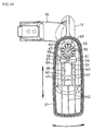
- FIG. 14 is a top plan view of the armrest from which a core, cushion material and an armrest pad are removed;
- FIG. 15 is a vertical sectional side view of a lower part of the second embodiment of an armrest height adjuster
- FIG. 16 is a vertical sectional front view thereof
- FIG. 17 is an exploded perspective view thereof seen from a position below.
- FIG. 18 is a perspective view of a cover.
- FIG. 1 is a perspective view of an embodiment of a chair comprising an armrest device according to the present invention
- FIG. 2 is a left side view thereof.
- the chair comprises a leg 3 that extends upright from five radially-extending feet 2 each of which comprises a caster 1 at the end; a support base 4 at the upper end of the leg 3 ; a seat 6 supported by a support link 5 over the support base 4 ; and a backrest 8 pivotally mounted to the support base 4 with a horizontal shaft 7 so that the backrest 8 may be inclined rearward; and an armrest device 9 extending upright from each side of the seat 6 .
- the armrest device 9 may extend upright from one side of the seat 6 .
- FIGS. 3-8 show the details of the armrest device 9 .
- the armrest device 9 comprises an armrest-support tube 11 in which a bracket 10 extending from the inside at the lower end is fixed to the lower surface of the seat 6 so that the tube 11 is inclined slightly forward from the side of the seat 6 ; an intermediate tube 12 which contacts the inner surface of the armrest support tube 11 ; an armrest support rod 14 which is placed in the intermediate tube 12 to slide up and down; and a height adjuster 15 which adjusts a height of the armrest support rod 14 with respect to the armrest support tube 11 .
- the armrest support tube 11 , the intermediate tube 12 and the armrest support rod 14 have elliptical cross-sections in which the major axis extending forward in the ellipse is slightly longer than the minor axis extending transversely. Other cross-sections may be accepted.
- the intermediate tube 12 comprises two semicylindrical pieces 12 A, 12 B bound to each other. At four corners of the semicylindrical pieces 12 A, 12 B, a groove 16 and a projection 17 engage with each other when they face each other at a normal position.
- an elastic engagement side claw 18 having an outward projection 18 a .
- the elastic claws 18 , 18 engage with engagement holes 19 of a bottom wall 11 a closing the lower end of the armrest support tube 11 in FIGS. 7 and 8 thereby preventing the intermediate tube 12 from detaching from the armrest support tube 11 while the semicylindrical pieces 12 A, 12 B are attached to each other.
- the height adjuster 15 comprises an operating lever 21 which comprises an operating portion 21 a projecting forward through a groove 20 in the upper surface of the armrest support rod 14 , a reversed U-shaped engagement groove 21 b at the rear end, and an intermediate portion pivotally mounted on the upper end of the armrest support rod 14 with a shaft 21 c ; a rhombus-shaped turning lever 22 which fits in the armrest support rod 14 to turn around its middle and comprises at the upper end an axial portion 22 a which engages in the engagement groove 21 b of the operating lever 21 ; a pin-fitting hole 22 b through which a pin 24 passes via an elongate hole 23 in the side wall of the armrest support rod 14 at the lower end; and an elongate portion 25 a formed in each of the semicylindrical pieces 12 A, 12 B of the intermediate tube 12 .
- the ends of the pin 24 project from the sides of the armrest support rod 14 through the elongate portion 25 a .
- the shaft 21 c fits in a pair of grooves 26 in the upper end of the armrest support rod 14 , and the lower surface of a closing member 27 for closing the upper opening of the armrest support rod 14 contacts the upper surface of the intermediate portion of the operating lever 21 , thereby preventing the shaft 21 c from coming off the groove 26 to allow the shaft 21 c to be mounted on the armrest support rod 14 easily.
- the closing member 27 is formed as a disc and fixed on the upper end of the armrest support rod 14 with a plurality of screws 28 to become part of the armrest support rod 14 .
- An upward shaft 29 having a noncircular axial portion 29 b like a rectangle at the upper end of a circular axial portion 29 a projects at the center on the upper surface of the closing member 27 .
- lobes 22 c contact the inner circumferential surface of the armrest support rod 14 and comprise arcs around the same center of curvature at the vertexes of the rhombus to allow the turning lever 22 to turn about the center of curvature of the lobes 22 c without a pivotal shaft.
- each of the semicylindrical pieces 12 A, 12 B comprises an elongate portion 25 a axially of the intermediate tube 12 ; and a plurality of engagement portions 25 b extending forward.
- the ends of the engagement pin 24 projecting sideward from the armrest support rod 14 engage in the elongate portion 25 a to enable the pin 24 and the armrest support rod 14 to move up and down along the intermediate tube 12 and the armrest support tube 11 .
- the pin 24 and the armrest support rod 14 cannot move.
- An elastic tongue 30 extending rearward is integrally formed at the lower end of the turning lever 22 .
- the end of the elastic tongue 30 pressingly contacts the rear inner circumferential surface of the armrest support rod 14 thereby enabling the turning lever 22 to be forced toward an engagement position where the pin 24 engages in any one of the elongate portions 25 b of the engagement opening 25 .
- the elastic tongue 30 plays a role of forcing the turning lever to where the pin 24 engages in any one of the engagement portions 25 b.
- the pin 24 engages in any one of the engagement portions 25 b by the elastic tongue 30 , so that the armrest 13 is held at height corresponding to the engagement portion 25 b and the operating lever 21 is positioned in an inoperative position where the operating portion 21 a projects forward of the groove 20 .
- the operating portion 21 a of the operating lever 21 is turned upward against the force of the elastic tongue 30 from the inoperative position as shown by an imaginary line in FIG. 8 .
- the rear engagement groove 21 b of the operating lever 21 is turned forward and the turning lever 22 of which the axial portion 22 a engages in the groove 21 b is turned anticlockwise as shown by an imaginary line in FIG. 8 , so that the pin 24 disengages from the engagement portion 25 b of the opening 25 and moves into the elongate portion 25 a in a disengagement position.
- the armrest 13 and the armrest support rod 14 are elevated or lowered to a desired height.
- the pin 24 in the elongate portion 25 a can move up and down along the elongate portion 25 a.
- the armrest 13 After the armrest 13 is kept in the desired height, a hand is released from the operating portion 21 a of the operating lever 21 or an operating force is loosened.
- the turning lever 22 is urged by the elastic tongue 30 to return to the original engagement position to allow the pin 24 to engage with the nearest engagement portion 25 b . If the pin 24 does not engage in the engagement portion 25 b suitably, the armrest 13 may be moved up and down slightly.
- the pin 24 engages in any one of the engagement portions 25 b and the turning lever 22 is returned to the engagement position.
- the operating lever 21 is returned to the inoperative position.
- the operating lever 21 is mounted to the armrest support rod 14 , the operating lever 21 is positioned and the turning lever 22 is inserted upward from the lower end of the armrest support rod 14 to allow the rear end of the operating lever 21 to engage with the upper end of the turning lever 22 via the engagement groove 21 b and to allow the elongate hole 23 of the armrest support rod 14 to coincide with the hole 22 b to facilitate assembling.
- the center of gravity of the operating lever 21 is positioned closer to the operating portion 21 a rather than the shaft 21 c to make the operating portion 21 a heavier thereby allowing the operating lever 21 to be positioned at the inoperative position.
- the turning lever 22 pressingly contacts the rear inner circumferential surface of the armrest support rod 14 to allow the turning lever 22 to be positioned at the engagement position thereby omitting special positioning means for the operating lever 21 and turning lever 22 .
- the elastic claws 18 , 18 engage in the hole 19 in the bottom wall 11 a of the armrest support tube 11 thereby assembling the armrest support tube 11 , the intermediate tube 12 , the armrest support rod 14 , the operating lever 21 , the turning lever 22 etc. simply and surely.
- the structure of the armrest 13 will be described with respect to FIG. 3 and FIGS. 8-14 .
- the armrest 13 comprises a horizontal armrest base plate 31 made of synthetic resin; a core 32 made of soft synthetic resin and covering the upper surface of the base plate 31 ; cushion material 33 made of foam polyurethane; and a arm pad 34 made of elastomer.
- a slot 35 is formed in the middle of the armrest base plate 31 and a peripheral projection 36 and a peripheral edge 37 are provided on the upper surface to hold the core 32 and the armrest pad 34 .
- the outer surface of the peripheral projection 36 has a plurality of slits 39 in which inward claws 38 of the core 32 engage.
- a pair of protrusions 40 , 40 is provided in parallel with the slot 35 .
- the protrusions 40 , 40 have a plurality of recesses 41 like a wave.
- a plurality of ribs 42 are provided on the upper surface longitudinally and transversely of the armrest base plate 31 .
- a rectangular recess 43 surrounds the slot 35 .
- a shielding plate 44 engages to be capable of sliding back and forth to prevent the slot 35 from being exposed when the armrest base plate 31 goes forward.
- the shielding plate 44 has a slot 45 in which an engagement portion of a support block 46 engages.
- the armrest 13 comprises the support block 46 and a fixed disc 47 to turn about a vertical axis and to move back and forth.
- the support block 46 comprises an engagement portion 48 having the same width as that of the slot 35 ; and a wider portion 49 on the engagement portion 48 .
- a circular axial portion 29 a of a shaft 29 of the closing member 27 engages in an axial hole 50 in the middle of the support block 46 to allow the support block 46 to turn on the armrest support rod 14 .
- the fixed disc 47 fits in a circular recess 51 in the upper surface of the wider portion 49 of the support block 46 .
- the non-circular axial portion 29 b of the shaft 29 fits in the rectangular hole 52 in the middle of the lower surface of the fixed disc 47 .
- the fixed disc 47 is fixed to the upper end of the shaft 29 with a screw 53 to prevent the support block 46 from disengaging from the shaft 29 .
- the armrest base plate 31 is disposed on the upper end of the armrest support rod 14 .
- the engagement portion 48 of the support block 46 engages in the slot 35 of the armrest base plate 31 and in the slot 45 of the shielding plate 44 .
- the armrest base plate 31 is put between the wider portion 49 of the support block 46 and the upper surface of the armrest support rod 14 .
- the armrest base plate 31 is mounted to the armrest support rod 14 to slide back and forth and to turn with the support block 46 about the shaft 29 .
- a rectangular hole 54 and a narrower communicating hole 55 which allows the rear middle of the rectangular hole 54 to communicate with the recess 51 .
- Force of an elastic member 56 such as rubber fitting in the rectangular hole 54 allows a vertical pin 57 in the communicating hole 55 to be pressed onto the outer circumferential surface of the fixed disc 47 thereby allowing the pin 57 to engage elastically on a plurality of recesses 58 on the outer circumferential surface of the fixed disc 47 , so that suitable stepwise resistant force is given to rotation of the support block 46 .
- a fan-shaped recess 59 having the same center as that of the axial hole 50 is formed to engage with a projection 60 on the outer circumferential surface of the fixed disc 47 thereby limiting a turning range of the support block.
- elastic downward tongues 61 , 61 are fixed on the upper part of the sides of the wider portion 49 of the support block 46 .
- a projection 61 a of each of the elastic tongues 61 is pressed onto the recess 41 of the projection 40 of the armrest base plate 31 thereby applying stepwise resistant force when the projection 61 a engages in the recess 41 elastically.
- the armrest base plate 31 comprising the slot 35 of the armrest base plate 31 and the engagement portion 48 of the support block 46 ; and relaxation-giving means comprising the recesses 41 in the projections 40 and the elastic tongues 61 at the side of the wider portion 49 of the support block 46 .
- Both the means are separated from each other to allow the armrest base plate 31 to move back and forth stably and smoothly.
- the projections 40 and the elastic tongues 61 are integrally formed with the armrest base plate 31 and the support block 46 respectively thereby saving the number of parts and facilitating assembly.
- the projections 40 and the elastic tongues 61 are symmetrically provided as a pair to surround the slot 35 of the armrest base plate 31 to enable the armrest base plate 31 to move back and forth stably and smoothly.
- the support block 46 can be turned about an axis extending perpendicular to the upper surface of the armrest support rod 14 to allow the armrest base plate 31 to slide back and forth with respect to the armrest support rod 14 and to turn transversely, so that the armrest base plate 31 can be moved back and forth smoothly and turned stably and smoothly in a transverse direction.
- the shielding plate 44 prevents the slot 35 of the armrest base plate 31 from exposing downward when the armrest base plate 31 is moved forward, thereby preventing a finger from being held by the slot 35 and providing good appearance.
- a plurality of recesses are arranged in the inner side surface of a projection to allow the end of a elastic tongue to press onto the inner side surface.
- FIGS. 15-18 show a variation of a height-adjuster of an armrest.
- a projection 71 fits in a hole 19 in a bottom wall 11 a of an armrest support tube 11 to prevent an elastic engagement side claw 18 from coming off the hole 19 and to prevent an intermediate tube 12 from coming off the armrest support tube 11 .
- the projections 71 are provided on the upper surface of a cover 72 covering the lower surface of the bottom wall 11 a of the armrest support tube 11 to allow the projection 71 to engage in the hole 19 easily.
- the bottom wall 11 a especially the hole 19 of the armrest support tube 11 , is covered with the cover 72 providing good appearance.
- a circular hole 73 is formed in the middle of the bottom wall 11 a of the armrest support tube 11 .
- a pair of arcuate elastic engagement claws 74 , 74 is provided at the lower end of the semicylindrical pieces 12 A, 12 B of the intermediate tube 12 to engage on the edge of the circular hole 73 .
- the cover 72 has in the middle a middle projection 75 which engages between elastic engagement middle claws 74 and 74 in the circular hole 73 to prevent the middle claws 74 from elastically flexing inwards, and elastic projections 76 , 76 which engage with the edge of the hole 73 .
- the intermediate tube 12 is prevented from coming off the armrest support tube 11 .
Abstract
Description
Claims (8)
Applications Claiming Priority (12)
| Application Number | Priority Date | Filing Date | Title |
|---|---|---|---|
| JP2007-30239 | 2007-02-09 | ||
| JP2007030239A JP2008194125A (en) | 2007-02-09 | 2007-02-09 | Armrest device in chair |
| JP2007-030240 | 2007-02-09 | ||
| JP2007030240A JP2008194126A (en) | 2007-02-09 | 2007-02-09 | Armrest device in chair |
| JP2007-030239 | 2007-02-09 | ||
| JP2007-30240 | 2007-02-09 | ||
| JP2007032412A JP5154091B2 (en) | 2007-02-13 | 2007-02-13 | Chair armrest equipment |
| JP2007-32412 | 2007-02-13 | ||
| JP2007-032413 | 2007-02-13 | ||
| JP2007-032412 | 2007-02-13 | ||
| JP2007032413A JP2008194229A (en) | 2007-02-13 | 2007-02-13 | Height adjuster of armrest in chair |
| JP2007-32413 | 2007-02-13 |
Publications (2)
| Publication Number | Publication Date |
|---|---|
| US20080191537A1 US20080191537A1 (en) | 2008-08-14 |
| US7828389B2 true US7828389B2 (en) | 2010-11-09 |
Family
ID=39678563
Family Applications (1)
| Application Number | Title | Priority Date | Filing Date |
|---|---|---|---|
| US11/939,869 Expired - Fee Related US7828389B2 (en) | 2007-02-09 | 2007-11-14 | Armrest device in a chair |
Country Status (2)
| Country | Link |
|---|---|
| US (1) | US7828389B2 (en) |
| CA (1) | CA2610533C (en) |
Cited By (43)
| Publication number | Priority date | Publication date | Assignee | Title |
|---|---|---|---|---|
| US20110248542A1 (en) * | 2010-04-13 | 2011-10-13 | Po-Chuan Tsai | Chair Armrest Assembly Having Adjustable Height |
| US20120175933A1 (en) * | 2011-01-12 | 2012-07-12 | Hsuan-Chin Tsai | Adjustment Structure for Chair Armrest |
| CN102949025A (en) * | 2011-08-24 | 2013-03-06 | 艺术达科技材料股份有限公司 | Multi-facet armchair armrest structure |
| US8403417B2 (en) * | 2011-08-03 | 2013-03-26 | Tsung-Wen Huang | Armrest structure |
| USD683150S1 (en) | 2012-09-20 | 2013-05-28 | Steelcase Inc. | Chair |
| USD683151S1 (en) | 2012-09-20 | 2013-05-28 | Steelcase Inc. | Chair |
| USD688497S1 (en) | 2012-09-20 | 2013-08-27 | Steelcase Inc. | Chair |
| USD688499S1 (en) | 2012-09-20 | 2013-08-27 | Steelcase Inc. | Chair |
| USD688502S1 (en) | 2012-09-20 | 2013-08-27 | Steelcase Inc. | Arm assembly |
| USD688907S1 (en) | 2012-09-20 | 2013-09-03 | Steelcase Inc. | Arm assembly |
| USD689313S1 (en) | 2012-09-20 | 2013-09-10 | Steelcase Inc. | Chair |
| USD689312S1 (en) | 2012-09-20 | 2013-09-10 | Steelcase Inc. | Chair |
| USD689314S1 (en) | 2012-09-20 | 2013-09-10 | Steelcase Inc. | Chair |
| USD690146S1 (en) | 2012-09-20 | 2013-09-24 | Steelcase Inc. | Chair |
| USD694537S1 (en) | 2012-09-20 | 2013-12-03 | Steelcase Inc. | Chair |
| USD694538S1 (en) | 2012-09-20 | 2013-12-03 | Steelcase Inc. | Chair |
| USD694540S1 (en) | 2012-09-20 | 2013-12-03 | Steelcase Inc. | Chair |
| US20130320739A1 (en) * | 2012-06-01 | 2013-12-05 | Atec International Team Co., Ltd. | Height adjustment mechanism for armrest |
| USD697726S1 (en) | 2012-09-20 | 2014-01-21 | Steelcase Inc. | Chair |
| USD697730S1 (en) | 2012-09-20 | 2014-01-21 | Steelcase Inc. | Chair |
| USD697729S1 (en) | 2012-09-20 | 2014-01-21 | Steelcase Inc. | Chair |
| USD697727S1 (en) | 2012-09-20 | 2014-01-21 | Steeelcase Inc. | Chair |
| USD698165S1 (en) | 2012-09-20 | 2014-01-28 | Steelcase Inc. | Chair |
| USD699957S1 (en) | 2012-09-20 | 2014-02-25 | Steelcase Inc. | Chair |
| US8960104B2 (en) | 2012-04-27 | 2015-02-24 | Steelcase Inc. | Table |
| US8998339B2 (en) | 2012-09-20 | 2015-04-07 | Steelcase Inc. | Chair assembly with upholstery covering |
| WO2015157000A1 (en) | 2014-04-11 | 2015-10-15 | Knoll, Inc. | Armrest mechanism for a chair |
| USD758774S1 (en) | 2015-04-24 | 2016-06-14 | Steelcase Inc. | Headrest assembly |
| USD759415S1 (en) | 2015-04-24 | 2016-06-21 | Steelcase Inc. | Headrest |
| USD760526S1 (en) | 2015-04-24 | 2016-07-05 | Steelcase Inc. | Headrest assembly |
| USD781605S1 (en) | 2015-04-24 | 2017-03-21 | Steelcase Inc. | Chair |
| USD781604S1 (en) | 2015-04-24 | 2017-03-21 | Steelcase Inc. | Chair |
| US9609948B2 (en) * | 2015-04-28 | 2017-04-04 | Qianglong Furniture Co., Ltd. | Rotating armrest apparatus |
| US10201465B2 (en) * | 2014-08-29 | 2019-02-12 | Panasonic Intellectual Property Management Co., Ltd. | Armrest locking mechanism and integrated bed having same |
| WO2019143516A1 (en) | 2018-01-22 | 2019-07-25 | Knoll, Inc. | Fastenerless arm pad attachment mechanism |
| US10660445B2 (en) * | 2018-10-24 | 2020-05-26 | Tien Ching Fang | Height adjustable chair armrest |
| USD888479S1 (en) | 2018-06-04 | 2020-06-30 | Steelcase Inc. | Chair arm |
| USD891842S1 (en) | 2018-06-04 | 2020-08-04 | Steelcase Inc. | Chair arm |
| US10786082B1 (en) * | 2019-04-17 | 2020-09-29 | Yu-Shan Lai | Rotational adjuster of armrest |
| US11083301B2 (en) | 2018-06-01 | 2021-08-10 | Steelcase Inc. | Seating arrangement |
| US11229294B2 (en) | 2012-09-20 | 2022-01-25 | Steelcase Inc. | Chair assembly with upholstery covering |
| USD942767S1 (en) | 2012-09-20 | 2022-02-08 | Steelcase Inc. | Chair assembly |
| US11304528B2 (en) | 2012-09-20 | 2022-04-19 | Steelcase Inc. | Chair assembly with upholstery covering |
Families Citing this family (18)
| Publication number | Priority date | Publication date | Assignee | Title |
|---|---|---|---|---|
| US7744159B2 (en) * | 2008-02-11 | 2010-06-29 | Isotech Products Incorporated | Height adjustment mechanism for armrest |
| TWM361288U (en) * | 2009-03-27 | 2009-07-21 | zhi-tang Bai | Armrest structure of seat |
| US20110062763A1 (en) * | 2009-09-14 | 2011-03-17 | Po-Chuan Tsai | Adjustable Armrest Support Assembly for Chair |
| GB2477111B (en) * | 2010-01-22 | 2011-12-21 | Sian-Mao Wang | Armrest assembly with armrest capable of moving forward and backward and rotating sideways |
| TWM419484U (en) * | 2011-03-21 | 2012-01-01 | Isotech Products Inc | Multi-functional chair armrest adjustment device |
| US9307839B2 (en) * | 2012-12-31 | 2016-04-12 | Sava Cvek | Adjustable armrest |
| DE102013103382A1 (en) * | 2013-04-04 | 2014-10-09 | Recaro Aircraft Seating Gmbh & Co. Kg | armrests device |
| TWM477836U (en) * | 2013-12-26 | 2014-05-11 | Atec Internat Team Co Ltd | Structure of adjusting mechanism for armrest |
| US9004603B1 (en) * | 2014-03-30 | 2015-04-14 | Chih-Wei Wang | Armrest assembly for a chair |
| WO2016168185A1 (en) * | 2015-04-13 | 2016-10-20 | Steelcase Inc. | Seating arrangement |
| US10194750B2 (en) | 2015-04-13 | 2019-02-05 | Steelcase Inc. | Seating arrangement |
| USD759993S1 (en) * | 2015-05-28 | 2016-06-28 | Constance Stinson | Cover for chair arm |
| US9700139B2 (en) * | 2015-08-02 | 2017-07-11 | Dongguan Kentec Office Seating Co., Ltd. | Armrest structure for a chair |
| CN112773122B (en) * | 2019-11-07 | 2024-01-30 | 堡胜企业股份有限公司 | Rotary positioning mechanism, armrest frame with rotatable armrest seat and chair |
| CN110693638B (en) * | 2019-11-15 | 2021-09-03 | 武文亮 | Correction device for spinal surgery |
| JP2023539015A (en) * | 2020-07-22 | 2023-09-13 | フォームウェイ ファーニチャー リミティド | arm assembly for chair |
| CN114179612B (en) * | 2021-12-22 | 2023-09-26 | 奇瑞汽车股份有限公司 | Automobile auxiliary instrument board structure |
| CN114569263B (en) * | 2022-03-30 | 2023-09-08 | 宁波科艺医疗器械有限公司 | Automatic seat of electronic automatically controlled operation doctor |
Citations (15)
| Publication number | Priority date | Publication date | Assignee | Title |
|---|---|---|---|---|
| US5265938A (en) * | 1991-12-05 | 1993-11-30 | Westinghouse Electric Corp. | Adjustable arm for a chair |
| US5382079A (en) * | 1993-10-25 | 1995-01-17 | Chromcraft Revington, Inc. | Adjustable arm attachable to a chair body |
| US5439267A (en) * | 1993-05-28 | 1995-08-08 | Steelcase Inc. | Chair with adjustable arm assemblies |
| JPH09173178A (en) | 1995-12-25 | 1997-07-08 | Okamura Corp | Height adjustment device for chair armrest or the like |
| US5664842A (en) * | 1996-05-24 | 1997-09-09 | Shin Yeh Enterprise Co., Ltd. | Height-adjustable armrest unit for a chair |
| US5931537A (en) * | 1997-09-30 | 1999-08-03 | Gollin & Co., Inc. | Adjustable chair arm assembly |
| JP2000279268A (en) | 1999-03-31 | 2000-10-10 | Okamura Corp | Height adjustment device for chair armrest or the like |
| US6139107A (en) * | 2000-03-17 | 2000-10-31 | Lee; Ching-Yang | Armrest adjusting mechanism |
| JP2002051871A (en) | 2000-08-11 | 2002-02-19 | Okamura Corp | Elbow rest device for chair |
| US6540300B2 (en) * | 2000-06-06 | 2003-04-01 | Pro-Cord S.P.A. | Armrest for chair, armchair or similar, a chair using said armrest |
| US6824218B1 (en) * | 2004-01-30 | 2004-11-30 | Knoll, Inc. | Height adjustment mechanism for a chair |
| JP2005185619A (en) | 2003-12-26 | 2005-07-14 | Okamura Corp | Device for adjusting height of armrest or the like of chair |
| JP2005192766A (en) | 2004-01-07 | 2005-07-21 | Okamura Corp | Armrest device of seat |
| JP2005211245A (en) | 2004-01-28 | 2005-08-11 | Okamura Corp | Armrest device for chair |
| US20080296955A1 (en) * | 2007-06-01 | 2008-12-04 | Geister Jennifer K | Height adjustable armrest |
-
2007
- 2007-11-14 CA CA2610533A patent/CA2610533C/en not_active Expired - Fee Related
- 2007-11-14 US US11/939,869 patent/US7828389B2/en not_active Expired - Fee Related
Patent Citations (15)
| Publication number | Priority date | Publication date | Assignee | Title |
|---|---|---|---|---|
| US5265938A (en) * | 1991-12-05 | 1993-11-30 | Westinghouse Electric Corp. | Adjustable arm for a chair |
| US5439267A (en) * | 1993-05-28 | 1995-08-08 | Steelcase Inc. | Chair with adjustable arm assemblies |
| US5382079A (en) * | 1993-10-25 | 1995-01-17 | Chromcraft Revington, Inc. | Adjustable arm attachable to a chair body |
| JPH09173178A (en) | 1995-12-25 | 1997-07-08 | Okamura Corp | Height adjustment device for chair armrest or the like |
| US5664842A (en) * | 1996-05-24 | 1997-09-09 | Shin Yeh Enterprise Co., Ltd. | Height-adjustable armrest unit for a chair |
| US5931537A (en) * | 1997-09-30 | 1999-08-03 | Gollin & Co., Inc. | Adjustable chair arm assembly |
| JP2000279268A (en) | 1999-03-31 | 2000-10-10 | Okamura Corp | Height adjustment device for chair armrest or the like |
| US6139107A (en) * | 2000-03-17 | 2000-10-31 | Lee; Ching-Yang | Armrest adjusting mechanism |
| US6540300B2 (en) * | 2000-06-06 | 2003-04-01 | Pro-Cord S.P.A. | Armrest for chair, armchair or similar, a chair using said armrest |
| JP2002051871A (en) | 2000-08-11 | 2002-02-19 | Okamura Corp | Elbow rest device for chair |
| JP2005185619A (en) | 2003-12-26 | 2005-07-14 | Okamura Corp | Device for adjusting height of armrest or the like of chair |
| JP2005192766A (en) | 2004-01-07 | 2005-07-21 | Okamura Corp | Armrest device of seat |
| JP2005211245A (en) | 2004-01-28 | 2005-08-11 | Okamura Corp | Armrest device for chair |
| US6824218B1 (en) * | 2004-01-30 | 2004-11-30 | Knoll, Inc. | Height adjustment mechanism for a chair |
| US20080296955A1 (en) * | 2007-06-01 | 2008-12-04 | Geister Jennifer K | Height adjustable armrest |
Cited By (77)
| Publication number | Priority date | Publication date | Assignee | Title |
|---|---|---|---|---|
| US8128172B2 (en) * | 2010-04-13 | 2012-03-06 | Po-Chuan Tsai | Chair armrest assembly having adjustable height |
| US20110248542A1 (en) * | 2010-04-13 | 2011-10-13 | Po-Chuan Tsai | Chair Armrest Assembly Having Adjustable Height |
| US20120175933A1 (en) * | 2011-01-12 | 2012-07-12 | Hsuan-Chin Tsai | Adjustment Structure for Chair Armrest |
| US8328285B2 (en) * | 2011-01-12 | 2012-12-11 | Fuh Shyan Co., Ltd. | Adjustment structure for chair armrest |
| US8403417B2 (en) * | 2011-08-03 | 2013-03-26 | Tsung-Wen Huang | Armrest structure |
| CN102949025A (en) * | 2011-08-24 | 2013-03-06 | 艺术达科技材料股份有限公司 | Multi-facet armchair armrest structure |
| US8960104B2 (en) | 2012-04-27 | 2015-02-24 | Steelcase Inc. | Table |
| US20130320739A1 (en) * | 2012-06-01 | 2013-12-05 | Atec International Team Co., Ltd. | Height adjustment mechanism for armrest |
| US8777318B2 (en) * | 2012-06-01 | 2014-07-15 | Atec International Team Co., Ltd. | Height adjustment mechanism for armrest |
| USD699958S1 (en) | 2012-09-20 | 2014-02-25 | Steelcase Inc. | Chair |
| US8998339B2 (en) | 2012-09-20 | 2015-04-07 | Steelcase Inc. | Chair assembly with upholstery covering |
| USD688907S1 (en) | 2012-09-20 | 2013-09-03 | Steelcase Inc. | Arm assembly |
| USD689313S1 (en) | 2012-09-20 | 2013-09-10 | Steelcase Inc. | Chair |
| USD689312S1 (en) | 2012-09-20 | 2013-09-10 | Steelcase Inc. | Chair |
| USD689318S1 (en) | 2012-09-20 | 2013-09-10 | Steelcase Inc. | Chair |
| USD689317S1 (en) | 2012-09-20 | 2013-09-10 | Steelcase Inc. | Chair |
| USD689315S1 (en) | 2012-09-20 | 2013-09-10 | Steelcase Inc. | Arm assembly |
| USD689319S1 (en) | 2012-09-20 | 2013-09-10 | Steelcase Inc. | Chair |
| USD689314S1 (en) | 2012-09-20 | 2013-09-10 | Steelcase Inc. | Chair |
| USD690146S1 (en) | 2012-09-20 | 2013-09-24 | Steelcase Inc. | Chair |
| USD690547S1 (en) | 2012-09-20 | 2013-10-01 | Steelcase Inc. | Chair |
| USD694537S1 (en) | 2012-09-20 | 2013-12-03 | Steelcase Inc. | Chair |
| USD694536S1 (en) | 2012-09-20 | 2013-12-03 | Steelcase Inc. | Chair |
| USD694538S1 (en) | 2012-09-20 | 2013-12-03 | Steelcase Inc. | Chair |
| USD694540S1 (en) | 2012-09-20 | 2013-12-03 | Steelcase Inc. | Chair |
| USD694539S1 (en) | 2012-09-20 | 2013-12-03 | Steelcase Inc. | Chair |
| USD688499S1 (en) | 2012-09-20 | 2013-08-27 | Steelcase Inc. | Chair |
| USD697726S1 (en) | 2012-09-20 | 2014-01-21 | Steelcase Inc. | Chair |
| USD697730S1 (en) | 2012-09-20 | 2014-01-21 | Steelcase Inc. | Chair |
| USD697729S1 (en) | 2012-09-20 | 2014-01-21 | Steelcase Inc. | Chair |
| USD697727S1 (en) | 2012-09-20 | 2014-01-21 | Steeelcase Inc. | Chair |
| USD697747S1 (en) | 2012-09-20 | 2014-01-21 | Steelcase Inc. | Chair |
| USD698166S1 (en) | 2012-09-20 | 2014-01-28 | Steelcase Inc. | Chair |
| USD698165S1 (en) | 2012-09-20 | 2014-01-28 | Steelcase Inc. | Chair |
| USD699061S1 (en) | 2012-09-20 | 2014-02-11 | Steelcase Inc. | Arm assembly |
| USD699959S1 (en) | 2012-09-20 | 2014-02-25 | Steelcase Inc. | Chair |
| USD699957S1 (en) | 2012-09-20 | 2014-02-25 | Steelcase Inc. | Chair |
| USD688497S1 (en) | 2012-09-20 | 2013-08-27 | Steelcase Inc. | Chair |
| USD701053S1 (en) | 2012-09-20 | 2014-03-18 | Steelcase Inc. | Chair |
| USD683151S1 (en) | 2012-09-20 | 2013-05-28 | Steelcase Inc. | Chair |
| USD683150S1 (en) | 2012-09-20 | 2013-05-28 | Steelcase Inc. | Chair |
| US8967724B2 (en) | 2012-09-20 | 2015-03-03 | Steelcase Inc. | Chair arm assembly |
| USD688502S1 (en) | 2012-09-20 | 2013-08-27 | Steelcase Inc. | Arm assembly |
| US9028001B2 (en) | 2012-09-20 | 2015-05-12 | Steelcase Inc. | Chair arm assembly |
| US11464341B2 (en) | 2012-09-20 | 2022-10-11 | Steelcase Inc. | Chair assembly with upholstery covering |
| USD742677S1 (en) | 2012-09-20 | 2015-11-10 | Steelcase Inc. | Chair |
| USD742676S1 (en) | 2012-09-20 | 2015-11-10 | Steelcase Inc. | Chair |
| US11304528B2 (en) | 2012-09-20 | 2022-04-19 | Steelcase Inc. | Chair assembly with upholstery covering |
| USD942767S1 (en) | 2012-09-20 | 2022-02-08 | Steelcase Inc. | Chair assembly |
| US11229294B2 (en) | 2012-09-20 | 2022-01-25 | Steelcase Inc. | Chair assembly with upholstery covering |
| US10842281B2 (en) | 2012-09-20 | 2020-11-24 | Steelcase Inc. | Control assembly for chair |
| US9408467B2 (en) | 2012-09-20 | 2016-08-09 | Steelcase Inc. | Chair assembly with upholstery covering |
| US9427085B2 (en) | 2012-09-20 | 2016-08-30 | Steelcase Inc. | Chair arm assembly |
| US10835041B2 (en) | 2012-09-20 | 2020-11-17 | Steelcase Inc. | Chair arm assembly |
| US10264889B2 (en) | 2012-09-20 | 2019-04-23 | Steelcase Inc. | Chair assembly with upholstery covering |
| US10213019B2 (en) | 2012-09-20 | 2019-02-26 | Steelcase Inc. | Chair arm assembly |
| US9826839B2 (en) | 2012-09-20 | 2017-11-28 | Steelcase Inc. | Chair assembly with upholstery covering |
| US9872565B2 (en) | 2012-09-20 | 2018-01-23 | Steelcase Inc. | Chair arm assembly |
| WO2015157000A1 (en) | 2014-04-11 | 2015-10-15 | Knoll, Inc. | Armrest mechanism for a chair |
| US9351575B2 (en) | 2014-04-11 | 2016-05-31 | Knoll, Inc. | Armrest mechanism for a chair |
| US9861205B2 (en) | 2014-04-11 | 2018-01-09 | Knoll, Inc. | Armrest mechanism for a chair |
| US10201465B2 (en) * | 2014-08-29 | 2019-02-12 | Panasonic Intellectual Property Management Co., Ltd. | Armrest locking mechanism and integrated bed having same |
| USD781605S1 (en) | 2015-04-24 | 2017-03-21 | Steelcase Inc. | Chair |
| USD781604S1 (en) | 2015-04-24 | 2017-03-21 | Steelcase Inc. | Chair |
| USD758774S1 (en) | 2015-04-24 | 2016-06-14 | Steelcase Inc. | Headrest assembly |
| USD759415S1 (en) | 2015-04-24 | 2016-06-21 | Steelcase Inc. | Headrest |
| USD760526S1 (en) | 2015-04-24 | 2016-07-05 | Steelcase Inc. | Headrest assembly |
| US9609948B2 (en) * | 2015-04-28 | 2017-04-04 | Qianglong Furniture Co., Ltd. | Rotating armrest apparatus |
| US11006759B2 (en) | 2018-01-22 | 2021-05-18 | Knoll, Inc. | Fastenerless arm pad attachment mechanism |
| US10463155B2 (en) | 2018-01-22 | 2019-11-05 | Knoll, Inc. | Fastenerless arm pad attachment mechanism |
| WO2019143516A1 (en) | 2018-01-22 | 2019-07-25 | Knoll, Inc. | Fastenerless arm pad attachment mechanism |
| US11083301B2 (en) | 2018-06-01 | 2021-08-10 | Steelcase Inc. | Seating arrangement |
| US11800935B2 (en) | 2018-06-01 | 2023-10-31 | Steelcase Inc. | Seating arrangement |
| USD891842S1 (en) | 2018-06-04 | 2020-08-04 | Steelcase Inc. | Chair arm |
| USD888479S1 (en) | 2018-06-04 | 2020-06-30 | Steelcase Inc. | Chair arm |
| US10660445B2 (en) * | 2018-10-24 | 2020-05-26 | Tien Ching Fang | Height adjustable chair armrest |
| US10786082B1 (en) * | 2019-04-17 | 2020-09-29 | Yu-Shan Lai | Rotational adjuster of armrest |
Also Published As
| Publication number | Publication date |
|---|---|
| CA2610533A1 (en) | 2008-08-09 |
| CA2610533C (en) | 2011-11-01 |
| US20080191537A1 (en) | 2008-08-14 |
Similar Documents
| Publication | Publication Date | Title |
|---|---|---|
| US7828389B2 (en) | Armrest device in a chair | |
| US20060071525A1 (en) | Seat slide adjustment mechanism | |
| US20060244295A1 (en) | Chair | |
| US6347833B1 (en) | High chair having a seat-tilting mechanism | |
| US20030178876A1 (en) | Multi-task mid-pivot chair control mechanism | |
| JP5653601B2 (en) | Armrest device and chair equipped with the same | |
| JP2001029162A (en) | Chair with synchronously inclining seat and backrest | |
| US6422652B1 (en) | Height adjusting mechanism | |
| US6957864B2 (en) | Chair with a stopping device | |
| JP2008194127A (en) | Armrest device in chair | |
| JP4456453B2 (en) | Seat front / rear sliding device in a chair | |
| JP3989765B2 (en) | Gas spring for chair | |
| JP4842003B2 (en) | Chair | |
| JP2006102148A5 (en) | ||
| JP2008194125A (en) | Armrest device in chair | |
| JP3675144B2 (en) | Chair armrest device | |
| JP2006102148A (en) | Seat forward/backward sliding device for chair | |
| JP2006102147A (en) | Seat forward/backward sliding device for chair | |
| JP4491317B2 (en) | Chair seat structure | |
| JP4384003B2 (en) | Gas spring operating device for chair | |
| JP5884428B2 (en) | Chair back pivoting device | |
| JP3637755B2 (en) | Chair armrest device | |
| JPH0515793Y2 (en) | ||
| JP4384002B2 (en) | Gas spring operating device for chair | |
| JP3675142B2 (en) | Chair armrest device |
Legal Events
| Date | Code | Title | Description |
|---|---|---|---|
| AS | Assignment |
Owner name: OKAMURA CORPORATION, JAPAN Free format text: ASSIGNMENT OF ASSIGNORS INTEREST;ASSIGNOR:ODA, YOUICHIROU;REEL/FRAME:020111/0132 Effective date: 20071108 |
|
| STCF | Information on status: patent grant |
Free format text: PATENTED CASE |
|
| FEPP | Fee payment procedure |
Free format text: PAYOR NUMBER ASSIGNED (ORIGINAL EVENT CODE: ASPN); ENTITY STATUS OF PATENT OWNER: LARGE ENTITY |
|
| FPAY | Fee payment |
Year of fee payment: 4 |
|
| MAFP | Maintenance fee payment |
Free format text: PAYMENT OF MAINTENANCE FEE, 8TH YEAR, LARGE ENTITY (ORIGINAL EVENT CODE: M1552) Year of fee payment: 8 |
|
| FEPP | Fee payment procedure |
Free format text: MAINTENANCE FEE REMINDER MAILED (ORIGINAL EVENT CODE: REM.); ENTITY STATUS OF PATENT OWNER: LARGE ENTITY |
|
| LAPS | Lapse for failure to pay maintenance fees |
Free format text: PATENT EXPIRED FOR FAILURE TO PAY MAINTENANCE FEES (ORIGINAL EVENT CODE: EXP.); ENTITY STATUS OF PATENT OWNER: LARGE ENTITY |
|
| STCH | Information on status: patent discontinuation |
Free format text: PATENT EXPIRED DUE TO NONPAYMENT OF MAINTENANCE FEES UNDER 37 CFR 1.362 |
|
| FP | Lapsed due to failure to pay maintenance fee |
Effective date: 20221109 |