US7814436B2 - 3D scene orientation indicator system with scene orientation change capability - Google Patents
3D scene orientation indicator system with scene orientation change capability Download PDFInfo
- Publication number
- US7814436B2 US7814436B2 US10/627,974 US62797403A US7814436B2 US 7814436 B2 US7814436 B2 US 7814436B2 US 62797403 A US62797403 A US 62797403A US 7814436 B2 US7814436 B2 US 7814436B2
- Authority
- US
- United States
- Prior art keywords
- view
- scene
- display
- controls
- compass
- Prior art date
- Legal status (The legal status is an assumption and is not a legal conclusion. Google has not performed a legal analysis and makes no representation as to the accuracy of the status listed.)
- Active, expires
Links
Images


Classifications
-
- G—PHYSICS
- G06—COMPUTING; CALCULATING OR COUNTING
- G06F—ELECTRIC DIGITAL DATA PROCESSING
- G06F3/00—Input arrangements for transferring data to be processed into a form capable of being handled by the computer; Output arrangements for transferring data from processing unit to output unit, e.g. interface arrangements
- G06F3/01—Input arrangements or combined input and output arrangements for interaction between user and computer
- G06F3/048—Interaction techniques based on graphical user interfaces [GUI]
- G06F3/0481—Interaction techniques based on graphical user interfaces [GUI] based on specific properties of the displayed interaction object or a metaphor-based environment, e.g. interaction with desktop elements like windows or icons, or assisted by a cursor's changing behaviour or appearance
- G06F3/04815—Interaction with a metaphor-based environment or interaction object displayed as three-dimensional, e.g. changing the user viewpoint with respect to the environment or object
Definitions
- the present invention is directed to a widget or graphical user interface (GUI) element that depicts three-dimensional (3D) scene orientation and includes direction indicating controls that allow a user to orient a view of the 3D scene to align with the direction indicated by the selected control and, more particularly, to a GUI element that is resident within the 3D scene, stays aligned with the scene as the scene is tumbled by the user, remains in the same position and at the same size in the display as the view changes, and has controls that automatically rotate the scene to a predetermined view when selected where a scene object is centered in the display and sized to fit the display.
- GUI graphical user interface
- Conventional interfaces 10 in the 3D art can include an orientation gnomon 12 located in a display associated with a 3D scene 14 . As the view changes, the gnomon in the display is adjusted to reflect changes in the view into the scene. The gnomon can also be located in the center of the scene or at the origin of the axes of the 3D scene. This gnomon cannot be used to change a view of the 3D scene.
- What is needed is a gnomon that can be used to change a view of a 3D scene.
- FIG. 1 depicts a pending selection of a back view.
- the menu selection view change process requires that the user move through a number of different menu levels (3 in this example) to make such a selection, which takes time that may be considered wasted.
- the menu selection needed to get the desired view based on the current view is often not readily apparent especially to an unsophisticated user.
- What is needed is a system that provides the user with orientation information and selectable controls for view manipulation that do not require a complex selection process and that visually guide the user to a desired view with directional aids associated with the selection controls.
- orientation indicator with direction indicators associated with the controls that indicate the direction of the various views that can be selected.
- the above aspects can be attained by a system that provides an orientation indicator graphical user interface element in a three-dimensional scene where the orientation indicator can be used to automatically change a view of the scene to a predetermined viewpoint.
- the indicator includes controls that when activated or selected cause the view of the scene to change to a view direction indicated by the control.
- the view direction associated with a particular control can be indicated by a shape of the control or by the location of a control.
- the view of the scene is also automatically adjusted at the selected view position to center an object of interest in the scene in the display view and to fit the object to the display view.
- the indicator is moved about within the scene and changed in size to position the indicator at a predetermined fixed position in the users display view and at a predetermined fixed size.
- FIG. 1 illustrates a conventional 3D display with a menu for selecting a view of a scene to be displayed.
- FIG. 2 depicts a view compass or GUI element according to the present invention.
- FIG. 3 shows a view compass in a 3D scene.
- FIGS. 4-7 illustrate changes in view of a scene and corresponding changes in the view compass.
- FIG. 8 illustrates a handle/control of the compass being highlighted as a cursor passes over the handle.
- FIG. 9 illustrates the orientation after the handle highlighted in FIG. 8 has been selected.
- FIG. 10 is a flowchart of the process performed when a control of the compass is selected.
- FIGS. 11-17 illustrate additional embodiments of the present invention.
- FIG. 18 illustrates hardware of the present invention
- the present invention is a graphical user interface (GUI) orientation indicator element indicating the orientation of a three-dimensional (3D) scene that has directional buttons or controls that allow the orientation to be changed to align a display view of the scene with the direction indicated by a selected button.
- GUI graphical user interface
- the invention can be called a view compass GUI element, tool or widget or just a view compass.
- the view compass 30 is a collection of seven virtual buttons or handles 32 - 44 , represented as a 3D figure (widget) on a computer display.
- the buttons are conventional virtual buttons in that the operating system user interface recognizes that an action is to be taken when a cursor is on one of the buttons and a mouse button is activated or “clicked”.
- the compass 30 becomes or is an element of a 3D scene, such as those used for modeling, CAD, or videogames.
- These seven buttons or controls 32 - 44 provide shortcuts for moving the virtual camera in (or viewpoint of) the scene to pre-defined positions.
- the view compass 30 is unique in that its position is coupled to the virtual camera or the point of view into the 3D scene as established by an associated system, such as the Alias ImageStudioTM system, making it always available in the same place.
- the orientation of the compass 30 is locked to the orientation of the virtual 3D world, so that the action of each view-changing handle is visually obvious. This is a change from current ways of switching views in 3D software, as discussed above, that require the user to mentally calculate (or guess) which absolute position they need to switch to in order to get the view they want.
- the view compass 30 is drawn as a 3D figure, comprising a core handle (or control) 44 with six handles (or controls) 32 - 42 arranged peripherally around it (one handle on either side in each of the X, Y, and Z directions).
- the compass 30 preferably has a form, as depicted in FIG. 2 , that allows most or all of the handles to be visible (and therefore pick able) at any given time.
- a cubic core 44 with cone-shaped handles 32 - 42 but many other forms are possible as will be discussed later herein.
- the entire visible portion of a cone is a control.
- the preferred compass 30 includes cone shaped handles 32 - 42 where the point 46 of the cone preferably points in the direction of the virtual camera view point, which provides a visual and somewhat intuitive information about what view will be provided when the handle is selected.
- the compass 30 preferably also has some additional visual cues.
- One of the handles, in this case handle 44 is a different color to mark it as the “front” direction of the scene, and the system can label the positive X, Y, and Z axes associated with the handles (see FIG. 14 ). These refinements are not required to make the view compass work well, but are preferable additions.
- the first is how the compass 30 it behaves in the scene since it is part of the scene.
- the compass 30 changes with the scene. For example, as the scene is tumbled, because the compass is in the scene, the compass 30 also tumbles with the scene automatically maintaining an orientation that matches the orientation of the scene. However, as the scene is tumbled, the compass would normally move within the display view or virtual camera view of the scene provided to the user. As another example, because the compass is part of the scene, if the user zooms into the scene, the size as well as the position of the view compass 30 would be expected to change in the display image or display view presented to the user.
- the present invention preferably maintains the compass in the same position (preferably a display corner) and at the same size, as will be discussed in more detail below.
- a second aspect is how the displayed scene changes when a handle of the compass is selected. When a handle is activated the scene is switched to the viewpoint of the handle, the 3D scene object is centered and the display view is resized (zoom-in or zoom-out) so that the object fits within the display as will discussed in more detail later herein.
- the view compass 62 is preferably drawn in the view 64 that it controls. Its position and size are fixed relative to the virtual camera (and in terms of the number of pixels on the computer display, preferably about 110 by 110 pixels), but the compass 62 orientation is fixed relative to the 3D world coordinate system, as can be seen in FIG. 3 . This way, as the camera moves, the view compass 62 stays constantly at one size, in one out-of-the-way corner of the screen (upper right in FIG. 3 ). In this position, it also tumbles to match the orientation of the virtual world (note that the front position points along the axis of the ring in FIG. 3 ).
- the view compass 62 is preferably drawn last so that it is drawn on top of everything else in the scene. This ensures that the compass 62 is always visible, even if scene objects come between the compass 62 and the virtual camera. (Depending on the details of the particular graphics system being used, it may be necessary to turn off the z-buffer, or ensure that the compass is just past the near clipping plane.)
- the process set forth above starts by calculating how big the view compass would have to be in 3D space to maintain the same apparent size in pixels on the current display. This can change based on the focal length of the virtual camera, or on the size of the window in which the program is running.
- the process calculates where in 3D space the view compass would need to be located in order to maintain the same apparent position relative to the camera. Once that is done, the compass widget itself can be drawn in a conventional way.
- FIGS. 4-7 show a user tumbling the view from a perspective view ( FIG. 4 ) to an offset top view ( FIG. 5 ), then to an upside down view ( FIG. 6 ) and finally to a left side view ( FIG. 7 ).
- FIG. 4 the front cone of the compass 62 is pointing perspectively in alignment with the axis of the ring scene object 66 in the scene 64 .
- FIG. 5 shows the compass 62 also in the same corner and the same size as in FIG.
- FIG. 6 again shows the compass 62 in the upper right hand corner at the same size and tumbled to be in alignment with the scene 64 .
- FIG. 7 depicts the view compass 62 in a left side view aligned with the ring 66 , so that the front cone points in the axial direction of the ring 66 .
- each handle of the view compass 72 acts as a button or control.
- the handle is conventionally highlighted in the scene 74 to show that the handle will be picked if the user clicks-on or selects the handle.
- the camera moves to align its view direction with the axis of the cone as depicted in FIG. 9 . (That is, the camera turns around the scene to point the same way that the cone points.) After the click in FIG.
- the camera is now looking along the same axis as the clicked handle, down the center of the ring 76 in the scene 74 , and the screen is filled with the object of interest (the ring 76 in this example) as shown in FIG. 9 .
- the view compass 72 has the same relative position and size in the scene 74 , but has rotated to a new orientation, matching the worldview. Once in selected orientation, the virtual camera or display view is repositioned so that objects of interest in the scene are centered and made to fit into the view, as shown in FIG. 9 .
- the objects of interest depend on the application. For example, the view compass could focus on selected objects, or on all objects.
- the camera as shown in FIG. 9 , also switches from a perspective to an orthographic mode.
- the camera rolls to a predefined view such as the a predefined perspective view, such as the home view depicted in FIG. 8 . Again, the camera adjusts its position to ensure that all objects of interest are made to fit into the view.
- a predefined view such as the a predefined perspective view, such as the home view depicted in FIG. 8 .
- the camera adjusts its position to ensure that all objects of interest are made to fit into the view.
- FIG. 10 depicts a process 90 that is sequential. However, when implemented in an object-oriented language, such as the preferred C++ language, the tasks may be distributed into objects that may not be sequentially organized.
- a conventional operation highlights any handle over which the cursor passes and the process waits 92 for a selection. Where a selection is preferably first processed by the compass behavior software described herein. If the cursor is used to make a selection, such as by clicking a button on a mouse or engaging a key on a keyboard, the process leaves the wait state 92 , and a determination 94 is made as to whether the selection, cursor click-hit, is a selection of a control of the view compass.
- the selection event is passed 96 to other software of the system. If so, a determination 98 is made as to which handle or control has been hit. If the top handle is selected (hit), the view or virtual camera is conventionally rolled or tumbled 100 to display the top view to the user. If the bottom handle is selected (hit), the view is conventionally rolled 102 to display the bottom view. Likewise for the left ( 104 ), right ( 106 ), front ( 108 ) and back ( 110 ) views. When the home or core control is selected, the view provided to the user is rolled 112 to the perspective view. The system then conventionally centers 114 the object of interest and fits the display size to the object as previously discussed. Next, the view compass size and position are adjusted 116 in the 3D scene to place the compass in the desired predetermined position at the predetermined size. The system then returns to await another input event.
- the view compass of the present invention can have a number of different shapes or other features that allow the direction of the view to be visualized, that depict the orientation and that are easy to select.
- the cone shaped controls of FIG. 2 can be pyramid shaped. Arrows can be substituted for the cones.
- FIG. 11 depicts a compass 130 with axial indicators 132 , 134 and 136 for the xyz axes.
- FIG. 12 illustrates a compass 150 where balls 152 are the controls and the links 154 between the balls 152 indicate view direction. That is, the stick of the ball and stick combination points at the core indicating view direction.
- FIG. 13 shows a compass 160 where the views are indicated by planes or windows 162 .
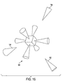
- FIG. 15 shows a compass 180 with view bookmarks 182 , 184 and 186 that indicate additional system or user created views to which the system can align the scene when selected.
- These additional views can be used for special purposes, such as in modeling where people often want to “bookmark” certain views, that is, save them because they contain an attractive angle for rendering, or because they are focused on a particular detail that they want to work with, and need to get back to periodically. Or, the user may be saving views of particular interest to point them out to a colleague. Additional components or scene views markers associated with the view compass can be provided as depicted in FIG. 16 .
- the view compass 200 has additional view markers, such as 202 , 204 and 206 , arbitrarily located at segment boundaries of a grid plane and that cause the display view to align with the particular plane of the view marker when selected.
- the view markers of the present invention can also be exploded as depicted in FIG. 17 where the display view 220 is of the entire 3D scene 222 and the markers or controls, such as controls 224 , 226 and 228 are located at the periphery of the scene.
- FIG. 18 illustrates hardware of the present invention where the 3D scene, including the view compass, is depicted on a display 250 , such as a CRT, PDP or LCD.
- a computer 252 such as desk top computer, runs the processes of the present invention, along with the 3D graphics software, that allow the user to manipulate the scene and select controls on the display, via input devices, such as a mouse 256 and keyboard 258 .
- Other input devices can also be used, such as tablets, gloves, etc., that allow a user to point at and select objects.
- the system of the present invention also includes permanent or removable storage, such as magnetic and optical discs, RAM, ROM, etc. on which the process and data structures of the present invention can be stored and distributed.
- the processes can also be distributed via, for example, downloading over a network such as the Internet.
- the present invention has been described with the visible part of each cone being a control. It is possible to have a region around each cone that also acts as a control.
- the axis labels (x, y, z) can also be part of the controls.
- the present invention has been described as making a front cone a different color to indicate a front direction of the compass and scene. It is possible to make a front face of the core 44 a different color either in addition to or as a substitute for the coloring of the front cone. Iconic representations of the contents of the scene from the various points of view can also be placed on the core faces.
- the compass as a tumbling tool such that dragging a cone will turn the scene. It is also possible to drag an image, such as a texture, and drop it on a cone and have the system paste the image on a part of the scene such as a wall.
Abstract
Description
| // Information required for this procedure: |
| // |
| point cameraPosition; // 3d position of the virtual camera |
| vector cameraDirection; // normalized vector in the direction of view |
| vector cameraUp; // normalized vector pointing “up” in camera-space |
| vector cameraRight; // normalized vector pointing “right” in camera-space |
| angle viewAngle; // horizontal angle of the view frustum of this camera |
| angle viewAngleV; // vertical angle of the view frustum of this camera |
| int viewportWidth; // width of the screen display in pixels |
| int viewportHeight; // height of the screen display in pixels |
| const int compassSize; // size of the view compass in pixels |
| const int compassOffset; | // offset of the view compass center |
| // from the corner in pixels |
| procedure drawViewCompass( camera, viewport ){ |
| // calculate the width/height of the viewing frustum at | |
| // one unit in front of the camera | |
| // | |
| float frustumWidth = 2.0 * sin(viewAngle*0.5)/cos(viewAngle*0.5); | |
| float frustumHeight = 2.0 * sin(viewAngleV*0.5)/ | |
| cos(viewAngleV*0.5); | |
| // calculate the width of a pixel at a distance one unit in front | |
| // of the camera | |
| // | |
| float pixelSize = (frustumWidth/viewportWidth); | |
| // calculate the size of the compass in real-world units | |
| // | |
| setCompassSize( compassSize * pixelSize ); | |
| // calculate the position of the compass center | |
| // | |
| setCompassPosition( cameraPosition + cameraDirection + |
| ((frustumWidth*0.5)−(pixelSize * compassOffset)) * | |
| cameraRight + | |
| ((frustumHeight*0.5)−(pixelSize * compassOffset)) * | |
| cameraUp); |
| // No need to set the orientation; it's always aligned with the | |
| // world. We can now draw the compass at the appropriate position, | |
| // size, and orientation. |
| . . . | ||
Claims (1)
Priority Applications (2)
| Application Number | Priority Date | Filing Date | Title |
|---|---|---|---|
| US10/627,974 US7814436B2 (en) | 2003-07-28 | 2003-07-28 | 3D scene orientation indicator system with scene orientation change capability |
| US12/805,970 US8132123B2 (en) | 2003-07-28 | 2010-08-26 | 3D scene orientation indicator system with scene orientation change capability |
Applications Claiming Priority (1)
| Application Number | Priority Date | Filing Date | Title |
|---|---|---|---|
| US10/627,974 US7814436B2 (en) | 2003-07-28 | 2003-07-28 | 3D scene orientation indicator system with scene orientation change capability |
Related Child Applications (1)
| Application Number | Title | Priority Date | Filing Date |
|---|---|---|---|
| US12/805,970 Continuation US8132123B2 (en) | 2003-07-28 | 2010-08-26 | 3D scene orientation indicator system with scene orientation change capability |
Publications (2)
| Publication Number | Publication Date |
|---|---|
| US20050028111A1 US20050028111A1 (en) | 2005-02-03 |
| US7814436B2 true US7814436B2 (en) | 2010-10-12 |
Family
ID=34103301
Family Applications (2)
| Application Number | Title | Priority Date | Filing Date |
|---|---|---|---|
| US10/627,974 Active 2025-12-11 US7814436B2 (en) | 2003-07-28 | 2003-07-28 | 3D scene orientation indicator system with scene orientation change capability |
| US12/805,970 Expired - Lifetime US8132123B2 (en) | 2003-07-28 | 2010-08-26 | 3D scene orientation indicator system with scene orientation change capability |
Family Applications After (1)
| Application Number | Title | Priority Date | Filing Date |
|---|---|---|---|
| US12/805,970 Expired - Lifetime US8132123B2 (en) | 2003-07-28 | 2010-08-26 | 3D scene orientation indicator system with scene orientation change capability |
Country Status (1)
| Country | Link |
|---|---|
| US (2) | US7814436B2 (en) |
Cited By (68)
| Publication number | Priority date | Publication date | Assignee | Title |
|---|---|---|---|---|
| US20080150892A1 (en) * | 2006-12-21 | 2008-06-26 | Canon Kabushiki Kaisha | Collection browser for image items with multi-valued attributes |
| US20080155474A1 (en) * | 2006-12-21 | 2008-06-26 | Canon Kabushiki Kaisha | Scrolling interface |
| US20090083626A1 (en) * | 2007-09-26 | 2009-03-26 | Autodesk, Inc. | Navigation system for a 3d virtual scene |
| US20090083627A1 (en) * | 2007-04-06 | 2009-03-26 | Ntt Docomo, Inc. | Method and System for Providing Information in Virtual Space |
| US20090141024A1 (en) * | 2007-12-04 | 2009-06-04 | Samsung Electronics Co., Ltd. | Image apparatus for providing three-dimensional (3d) pip image and image display method thereof |
| US20090226080A1 (en) * | 2008-03-10 | 2009-09-10 | Apple Inc. | Dynamic Viewing of a Three Dimensional Space |
| US20090256837A1 (en) * | 2008-04-11 | 2009-10-15 | Sidhartha Deb | Directing camera behavior in 3-d imaging system |
| US20100085351A1 (en) * | 2008-10-03 | 2010-04-08 | Sidhartha Deb | Depth of Field for a Camera in a Media-Editing Application |
| US20110134116A1 (en) * | 2005-03-02 | 2011-06-09 | Nintendo Co., Ltd. | Information processing program and information processing appartus |
| US20120229463A1 (en) * | 2011-03-11 | 2012-09-13 | J Touch Corporation | 3d image visual effect processing method |
| US20120256960A1 (en) * | 2004-06-22 | 2012-10-11 | Imran Chaudhri | Defining motion in a computer system with a graphical user interface |
| US20120268464A1 (en) * | 2010-01-07 | 2012-10-25 | Suzhou Superengine Graphics Software Co., Ltd. | Method and device for processing spatial data |
| US20120268463A1 (en) * | 2009-11-24 | 2012-10-25 | Ice Edge Business Solutions | Securely sharing design renderings over a network |
| US8390616B1 (en) * | 2003-08-07 | 2013-03-05 | Adobe Systems Incorporated | Markers for identifying projected graphics objects in object streams |
| US8397180B2 (en) | 2006-12-21 | 2013-03-12 | Canon Kabushiki Kaisha | Scrolling browser with previewing area |
| US8439733B2 (en) | 2007-06-14 | 2013-05-14 | Harmonix Music Systems, Inc. | Systems and methods for reinstating a player within a rhythm-action game |
| US8444464B2 (en) | 2010-06-11 | 2013-05-21 | Harmonix Music Systems, Inc. | Prompting a player of a dance game |
| US8465366B2 (en) | 2009-05-29 | 2013-06-18 | Harmonix Music Systems, Inc. | Biasing a musical performance input to a part |
| US8550908B2 (en) | 2010-03-16 | 2013-10-08 | Harmonix Music Systems, Inc. | Simulating musical instruments |
| US20130332889A1 (en) * | 2007-03-28 | 2013-12-12 | Autodesk, Inc. | Configurable viewcube controller |
| US20140032181A1 (en) * | 2012-07-24 | 2014-01-30 | Dassault Systemes | Design Operation In An Immersive Virtual Environment |
| US8663013B2 (en) | 2008-07-08 | 2014-03-04 | Harmonix Music Systems, Inc. | Systems and methods for simulating a rock band experience |
| US8678896B2 (en) | 2007-06-14 | 2014-03-25 | Harmonix Music Systems, Inc. | Systems and methods for asynchronous band interaction in a rhythm action game |
| US8686269B2 (en) | 2006-03-29 | 2014-04-01 | Harmonix Music Systems, Inc. | Providing realistic interaction to a player of a music-based video game |
| US8702485B2 (en) | 2010-06-11 | 2014-04-22 | Harmonix Music Systems, Inc. | Dance game and tutorial |
| US8751950B2 (en) | 2004-08-17 | 2014-06-10 | Ice Edge Business Solutions Ltd. | Capturing a user's intent in design software |
| US8762877B2 (en) | 2003-09-30 | 2014-06-24 | Ice Edge Business Solutions Ltd. | Creation and modification of valid functional design layouts |
| US8762941B2 (en) | 2006-02-16 | 2014-06-24 | Dirtt Environmental Solutions, Ltd. | Rendering and modifying CAD design entities in object-oriented applications |
| US8856684B2 (en) | 2006-12-21 | 2014-10-07 | Canon Kabushiki Kaisha | Scrolling interface |
| US9024166B2 (en) | 2010-09-09 | 2015-05-05 | Harmonix Music Systems, Inc. | Preventing subtractive track separation |
| US9035944B2 (en) | 2010-08-06 | 2015-05-19 | Intergraph Corporation | 3-D model view manipulation apparatus |
| US20150304724A1 (en) * | 2013-11-05 | 2015-10-22 | LiveStageº, Inc. | Multi vantage point player |
| US9189571B2 (en) | 2011-06-11 | 2015-11-17 | Ice Edge Business Solutions, Ltd. | Automated re-use of structural components |
| US9208608B2 (en) | 2012-05-23 | 2015-12-08 | Glasses.Com, Inc. | Systems and methods for feature tracking |
| US9236024B2 (en) | 2011-12-06 | 2016-01-12 | Glasses.Com Inc. | Systems and methods for obtaining a pupillary distance measurement using a mobile computing device |
| US9286715B2 (en) | 2012-05-23 | 2016-03-15 | Glasses.Com Inc. | Systems and methods for adjusting a virtual try-on |
| US9358456B1 (en) | 2010-06-11 | 2016-06-07 | Harmonix Music Systems, Inc. | Dance competition game |
| US9437033B2 (en) | 2008-11-05 | 2016-09-06 | Hover Inc. | Generating 3D building models with ground level and orthogonal images |
| US9437044B2 (en) | 2008-11-05 | 2016-09-06 | Hover Inc. | Method and system for displaying and navigating building facades in a three-dimensional mapping system |
| US9483853B2 (en) | 2012-05-23 | 2016-11-01 | Glasses.Com Inc. | Systems and methods to display rendered images |
| US9519407B2 (en) | 2008-03-11 | 2016-12-13 | Ice Edge Business Solutions, Ltd. | Automatically creating and modifying furniture layouts in design software |
| US20170024112A1 (en) * | 2015-07-22 | 2017-01-26 | Box, Inc. | Composing web-based interactive 3d scenes using high order visual editor commands |
| US9830681B2 (en) | 2014-01-31 | 2017-11-28 | Hover Inc. | Multi-dimensional model dimensioning and scale error correction |
| US9836881B2 (en) | 2008-11-05 | 2017-12-05 | Hover Inc. | Heat maps for 3D maps |
| US9934608B2 (en) | 2015-05-29 | 2018-04-03 | Hover Inc. | Graphical overlay guide for interface |
| US9953459B2 (en) | 2008-11-05 | 2018-04-24 | Hover Inc. | Computer vision database platform for a three-dimensional mapping system |
| US9981193B2 (en) | 2009-10-27 | 2018-05-29 | Harmonix Music Systems, Inc. | Movement based recognition and evaluation |
| US10038838B2 (en) | 2015-05-29 | 2018-07-31 | Hover Inc. | Directed image capture |
| US10127721B2 (en) | 2013-07-25 | 2018-11-13 | Hover Inc. | Method and system for displaying and navigating an optimal multi-dimensional building model |
| US10133830B2 (en) | 2015-01-30 | 2018-11-20 | Hover Inc. | Scaling in a multi-dimensional building model |
| US10178303B2 (en) | 2015-05-29 | 2019-01-08 | Hover Inc. | Directed image capture |
| US10220303B1 (en) | 2013-03-15 | 2019-03-05 | Harmonix Music Systems, Inc. | Gesture-based music game |
| US10296281B2 (en) | 2013-11-05 | 2019-05-21 | LiveStage, Inc. | Handheld multi vantage point player |
| US10357714B2 (en) | 2009-10-27 | 2019-07-23 | Harmonix Music Systems, Inc. | Gesture-based user interface for navigating a menu |
| US10410412B2 (en) | 2015-05-29 | 2019-09-10 | Hover Inc. | Real-time processing of captured building imagery |
| US10410413B2 (en) | 2015-05-29 | 2019-09-10 | Hover Inc. | Image capture for a multi-dimensional building model |
| US10416836B2 (en) * | 2016-07-11 | 2019-09-17 | The Boeing Company | Viewpoint navigation control for three-dimensional visualization using two-dimensional layouts |
| US10498741B2 (en) | 2016-09-19 | 2019-12-03 | Box, Inc. | Sharing dynamically changing units of cloud-based content |
| US10529145B2 (en) * | 2016-03-29 | 2020-01-07 | Mental Canvas LLC | Touch gestures for navigation and interacting with content in a three-dimensional space |
| US10592589B1 (en) | 2018-08-21 | 2020-03-17 | Axure Software Solutions, Inc. | Multi-view masters for graphical designs |
| US10769366B2 (en) | 2013-05-07 | 2020-09-08 | Axure Software Solutions, Inc. | Variable dimension version editing for graphical designs |
| US10861224B2 (en) | 2013-07-23 | 2020-12-08 | Hover Inc. | 3D building analyzer |
| US10884592B2 (en) | 2015-03-02 | 2021-01-05 | Apple Inc. | Control of system zoom magnification using a rotatable input mechanism |
| US11402968B2 (en) | 2014-09-02 | 2022-08-02 | Apple Inc. | Reduced size user in interface |
| US11574439B2 (en) | 2013-07-23 | 2023-02-07 | Hover Inc. | Systems and methods for generating three dimensional geometry |
| US11721066B2 (en) | 2013-07-23 | 2023-08-08 | Hover Inc. | 3D building model materials auto-populator |
| US11790610B2 (en) | 2019-11-11 | 2023-10-17 | Hover Inc. | Systems and methods for selective image compositing |
| US11954795B2 (en) | 2020-11-13 | 2024-04-09 | Hover Inc. | Computer vision database platform for a three-dimensional mapping system |
Families Citing this family (52)
| Publication number | Priority date | Publication date | Assignee | Title |
|---|---|---|---|---|
| US7777761B2 (en) * | 2005-02-11 | 2010-08-17 | Deltasphere, Inc. | Method and apparatus for specifying and displaying measurements within a 3D rangefinder data set |
| US7974461B2 (en) | 2005-02-11 | 2011-07-05 | Deltasphere, Inc. | Method and apparatus for displaying a calculated geometric entity within one or more 3D rangefinder data sets |
| US7403268B2 (en) * | 2005-02-11 | 2008-07-22 | Deltasphere, Inc. | Method and apparatus for determining the geometric correspondence between multiple 3D rangefinder data sets |
| US7477359B2 (en) * | 2005-02-11 | 2009-01-13 | Deltasphere, Inc. | Method and apparatus for making and displaying measurements based upon multiple 3D rangefinder data sets |
| US7477360B2 (en) * | 2005-02-11 | 2009-01-13 | Deltasphere, Inc. | Method and apparatus for displaying a 2D image data set combined with a 3D rangefinder data set |
| DE102005007571A1 (en) * | 2005-02-18 | 2006-11-09 | Siemens Ag | Method for visualizing three-dimensional vector variables present and / or received by a data processing device with color-coded direction information and associated device |
| US8698844B1 (en) | 2005-04-16 | 2014-04-15 | Apple Inc. | Processing cursor movements in a graphical user interface of a multimedia application |
| WO2007035720A2 (en) * | 2005-09-20 | 2007-03-29 | Deltasphere, Inc. | Methods, systems, and computer program products for acquiring three-dimensional range information |
| US20070196789A1 (en) * | 2006-02-22 | 2007-08-23 | D4D Technologies, Lp | Compass tool display object for navigating a tooth model |
| US20070198208A1 (en) * | 2006-02-23 | 2007-08-23 | D4D Technologies, Lp | Compass tool display object for navigating a tooth model |
| US7782319B2 (en) * | 2007-03-28 | 2010-08-24 | Autodesk, Inc. | Three-dimensional orientation indicator and controller |
| US20090172600A1 (en) * | 2007-12-27 | 2009-07-02 | Zhang Yajun | System and Method of Orienting Building Representations |
| US8359549B1 (en) * | 2008-09-10 | 2013-01-22 | Adobe Systems Incorporated | Multiple-function user interactive tool for manipulating three-dimensional objects in a graphical user interface environment |
| US20100066731A1 (en) * | 2008-09-16 | 2010-03-18 | James Calvin Vecore | Configurator Process and System |
| JP4856728B2 (en) * | 2009-02-05 | 2012-01-18 | インターナショナル・ビジネス・マシーンズ・コーポレーション | Apparatus and method for supporting creation of assembly data |
| US8392853B2 (en) * | 2009-07-17 | 2013-03-05 | Wxanalyst, Ltd. | Transparent interface used to independently manipulate and interrogate N-dimensional focus objects in virtual and real visualization systems |
| US20110035700A1 (en) * | 2009-08-05 | 2011-02-10 | Brian Meaney | Multi-Operation User Interface Tool |
| US9665257B2 (en) * | 2009-12-28 | 2017-05-30 | Ancestry.Com Operations Inc. | Interactive modification of spacing constraints of genealogical charts with live feedback |
| US10140000B2 (en) * | 2010-07-30 | 2018-11-27 | Autodesk, Inc. | Multiscale three-dimensional orientation |
| KR101340797B1 (en) * | 2010-09-01 | 2013-12-11 | 주식회사 팬택 | Portable Apparatus and Method for Displaying 3D Object |
| CN102012782B (en) * | 2010-09-17 | 2013-06-05 | 深圳市融创天下科技股份有限公司 | Method and system for judging dragged moving direction |
| EP2523132A1 (en) * | 2011-05-11 | 2012-11-14 | Dassault Systèmes | Designing a three-dimensional modeled assembly of objects in a three-dimensional scene |
| US8957967B2 (en) * | 2011-06-03 | 2015-02-17 | Honeywell International Inc. | System and method to control surveillance cameras via three dimensional metaphor and cursor |
| US8964008B2 (en) * | 2011-06-17 | 2015-02-24 | Microsoft Technology Licensing, Llc | Volumetric video presentation |
| WO2013041103A2 (en) | 2011-09-21 | 2013-03-28 | Dalux Aps | Bim and display of 3d models on client devices |
| US20140218360A1 (en) * | 2011-09-21 | 2014-08-07 | Dalux Aps | Bim and display of 3d models on client devices |
| US9569066B2 (en) * | 2011-10-03 | 2017-02-14 | Google Inc. | Interface for navigating imagery |
| US20130265299A1 (en) | 2012-03-07 | 2013-10-10 | Willow Garage Inc. | Point cloud data hierarchy |
| US20130268862A1 (en) * | 2012-03-07 | 2013-10-10 | Willow Garage Inc. | Point cloud data hierarchy |
| US20140089834A1 (en) * | 2012-03-07 | 2014-03-27 | Willow Garage Inc. | Point cloud data hierarchy |
| US20130249899A1 (en) | 2012-03-07 | 2013-09-26 | Willow Garage Inc. | Point cloud data hierarchy |
| EP2669781B1 (en) * | 2012-05-30 | 2016-08-17 | Dassault Systèmes | A user interface for navigating in a three-dimensional environment |
| US9098516B2 (en) * | 2012-07-18 | 2015-08-04 | DS Zodiac, Inc. | Multi-dimensional file system |
| US20140040832A1 (en) * | 2012-08-02 | 2014-02-06 | Stephen Regelous | Systems and methods for a modeless 3-d graphics manipulator |
| US9678651B2 (en) | 2013-06-08 | 2017-06-13 | Apple Inc. | Mapping application with interactive compass |
| US20150007096A1 (en) * | 2013-06-28 | 2015-01-01 | Silicon Graphics International Corp. | Rotation of graphical scenes |
| KR101773116B1 (en) * | 2013-07-26 | 2017-08-31 | 삼성전자주식회사 | Image photographing apparatus and method thereof |
| JP6347934B2 (en) * | 2013-10-11 | 2018-06-27 | 株式会社デンソーテン | Image display device, image display system, image display method, and program |
| US20150135116A1 (en) * | 2013-11-14 | 2015-05-14 | Microsoft Corporation | Control user interface element for continuous variable |
| US20150172418A1 (en) * | 2013-12-13 | 2015-06-18 | Assemble Systems Llc | Real-Time Model-Based Collaboration and Presence |
| US9563340B2 (en) * | 2014-03-08 | 2017-02-07 | IntegrityWare, Inc. | Object manipulator and method of object manipulation |
| JP1525003S (en) * | 2014-03-10 | 2015-06-01 | ||
| US9672747B2 (en) | 2015-06-15 | 2017-06-06 | WxOps, Inc. | Common operating environment for aircraft operations |
| USD768155S1 (en) * | 2015-09-09 | 2016-10-04 | Tuf-Tite, Inc. | Display screen with graphical user interface |
| KR20170035755A (en) * | 2015-09-23 | 2017-03-31 | 엘지전자 주식회사 | Mobile terminal and method for controlling the same |
| CN106354418B (en) * | 2016-11-16 | 2019-07-09 | 腾讯科技(深圳)有限公司 | A kind of control method and device based on touch screen |
| US10984606B1 (en) * | 2018-06-21 | 2021-04-20 | Dassault Systemes Solidworks Corporation | Graphical user interface tool for orienting computer-aided design model |
| USD947892S1 (en) * | 2018-07-24 | 2022-04-05 | Magic Leap, Inc. | Display panel or portion thereof with a graphical user interface |
| US10686992B2 (en) * | 2018-07-31 | 2020-06-16 | Qualcomm Incorporated | Image orientation notification and adjustment |
| USD910055S1 (en) * | 2019-06-03 | 2021-02-09 | Apple Inc. | Electronic device with graphical user interface |
| US11842444B2 (en) * | 2021-06-02 | 2023-12-12 | Streem, Llc | Visualization of camera location in a real-time synchronized 3D mesh |
| CN114895995B (en) * | 2022-03-15 | 2024-03-15 | 网易(杭州)网络有限公司 | Control view generation method and device, electronic equipment and readable medium |
Citations (26)
| Publication number | Priority date | Publication date | Assignee | Title |
|---|---|---|---|---|
| US4539585A (en) * | 1981-07-10 | 1985-09-03 | Spackova Daniela S | Previewer |
| US4791478A (en) * | 1984-10-12 | 1988-12-13 | Gec Avionics Limited | Position indicating apparatus |
| US5303337A (en) * | 1990-02-28 | 1994-04-12 | Hitachi, Ltd. | Method and device for determining a viewing perspective for image production |
| US5511157A (en) * | 1993-12-13 | 1996-04-23 | International Business Machines Corporation | Connection of sliders to 3D objects to allow easy user manipulation and viewing of objects |
| US5588098A (en) * | 1991-11-22 | 1996-12-24 | Apple Computer, Inc. | Method and apparatus for direct manipulation of 3-D objects on computer displays |
| US5608850A (en) * | 1994-04-14 | 1997-03-04 | Xerox Corporation | Transporting a display object coupled to a viewpoint within or between navigable workspaces |
| US5734805A (en) * | 1994-06-17 | 1998-03-31 | International Business Machines Corporation | Apparatus and method for controlling navigation in 3-D space |
| US5825365A (en) * | 1995-02-03 | 1998-10-20 | Fujitsu Limited | Three-dimensional graphic apparatus simplifying neighboring arrangement |
| US5835692A (en) * | 1994-11-21 | 1998-11-10 | International Business Machines Corporation | System and method for providing mapping notation in interactive video displays |
| US5861889A (en) * | 1996-04-19 | 1999-01-19 | 3D-Eye, Inc. | Three dimensional computer graphics tool facilitating movement of displayed object |
| US5943037A (en) * | 1995-10-10 | 1999-08-24 | Snap-On Technologies, Inc. | Viewer orientation indicator for an illustration |
| US6040839A (en) * | 1997-01-31 | 2000-03-21 | Van Eldik; Benjamin J. | Referencing system and method for three-dimensional objects displayed on a computer generated display |
| US6046749A (en) * | 1996-08-09 | 2000-04-04 | Autodesk, Inc. | Method for the modification of three-dimensional objects |
| US6198487B1 (en) * | 1995-01-23 | 2001-03-06 | Intergraph Corporation | Ole for design and modeling |
| US6346938B1 (en) * | 1999-04-27 | 2002-02-12 | Harris Corporation | Computer-resident mechanism for manipulating, navigating through and mensurating displayed image of three-dimensional geometric model |
| US6597380B1 (en) * | 1998-03-16 | 2003-07-22 | Nec Corporation | In-space viewpoint control device for use in information visualization system |
| US20030156126A1 (en) * | 2002-02-18 | 2003-08-21 | Sumitomo Wiring Systems, Ltd. | Image display apparatus and method |
| US6664986B1 (en) * | 1997-05-20 | 2003-12-16 | Cadent Ltd. | Computer user interface for orthodontic use |
| US6941516B2 (en) * | 2001-08-06 | 2005-09-06 | Apple Computer, Inc. | Object movie exporter |
| US6987512B2 (en) * | 2001-03-29 | 2006-01-17 | Microsoft Corporation | 3D navigation techniques |
| US20060025679A1 (en) * | 2004-06-04 | 2006-02-02 | Viswanathan Raju R | User interface for remote control of medical devices |
| US7016824B2 (en) * | 2001-02-06 | 2006-03-21 | Geometrix, Inc. | Interactive try-on platform for eyeglasses |
| US7119819B1 (en) * | 1999-04-06 | 2006-10-10 | Microsoft Corporation | Method and apparatus for supporting two-dimensional windows in a three-dimensional environment |
| US7190365B2 (en) * | 2001-09-06 | 2007-03-13 | Schlumberger Technology Corporation | Method for navigating in a multi-scale three-dimensional scene |
| US7347690B2 (en) * | 1997-09-22 | 2008-03-25 | Russell A Jordan | Methods for use in dental articulation |
| US7353192B1 (en) * | 1999-02-16 | 2008-04-01 | Autobytel Inc. | Product configuration display system and method with user requested physical product alterations |
-
2003
- 2003-07-28 US US10/627,974 patent/US7814436B2/en active Active
-
2010
- 2010-08-26 US US12/805,970 patent/US8132123B2/en not_active Expired - Lifetime
Patent Citations (28)
| Publication number | Priority date | Publication date | Assignee | Title |
|---|---|---|---|---|
| US4539585A (en) * | 1981-07-10 | 1985-09-03 | Spackova Daniela S | Previewer |
| US4791478A (en) * | 1984-10-12 | 1988-12-13 | Gec Avionics Limited | Position indicating apparatus |
| US5303337A (en) * | 1990-02-28 | 1994-04-12 | Hitachi, Ltd. | Method and device for determining a viewing perspective for image production |
| US5588098A (en) * | 1991-11-22 | 1996-12-24 | Apple Computer, Inc. | Method and apparatus for direct manipulation of 3-D objects on computer displays |
| US5511157A (en) * | 1993-12-13 | 1996-04-23 | International Business Machines Corporation | Connection of sliders to 3D objects to allow easy user manipulation and viewing of objects |
| US5608850A (en) * | 1994-04-14 | 1997-03-04 | Xerox Corporation | Transporting a display object coupled to a viewpoint within or between navigable workspaces |
| US5734805A (en) * | 1994-06-17 | 1998-03-31 | International Business Machines Corporation | Apparatus and method for controlling navigation in 3-D space |
| US5835692A (en) * | 1994-11-21 | 1998-11-10 | International Business Machines Corporation | System and method for providing mapping notation in interactive video displays |
| US6198487B1 (en) * | 1995-01-23 | 2001-03-06 | Intergraph Corporation | Ole for design and modeling |
| US5825365A (en) * | 1995-02-03 | 1998-10-20 | Fujitsu Limited | Three-dimensional graphic apparatus simplifying neighboring arrangement |
| US5943037A (en) * | 1995-10-10 | 1999-08-24 | Snap-On Technologies, Inc. | Viewer orientation indicator for an illustration |
| US5861889A (en) * | 1996-04-19 | 1999-01-19 | 3D-Eye, Inc. | Three dimensional computer graphics tool facilitating movement of displayed object |
| US6281906B1 (en) * | 1996-08-09 | 2001-08-28 | Autodesk, Inc. | Method for the modification of three-dimensional objects |
| US6046749A (en) * | 1996-08-09 | 2000-04-04 | Autodesk, Inc. | Method for the modification of three-dimensional objects |
| US6801217B2 (en) * | 1996-08-09 | 2004-10-05 | Autodesk, Inc. | Determining and displaying geometric relationship between objects in a computer-implemented graphics system |
| US6040839A (en) * | 1997-01-31 | 2000-03-21 | Van Eldik; Benjamin J. | Referencing system and method for three-dimensional objects displayed on a computer generated display |
| US6664986B1 (en) * | 1997-05-20 | 2003-12-16 | Cadent Ltd. | Computer user interface for orthodontic use |
| US7347690B2 (en) * | 1997-09-22 | 2008-03-25 | Russell A Jordan | Methods for use in dental articulation |
| US6597380B1 (en) * | 1998-03-16 | 2003-07-22 | Nec Corporation | In-space viewpoint control device for use in information visualization system |
| US7353192B1 (en) * | 1999-02-16 | 2008-04-01 | Autobytel Inc. | Product configuration display system and method with user requested physical product alterations |
| US7119819B1 (en) * | 1999-04-06 | 2006-10-10 | Microsoft Corporation | Method and apparatus for supporting two-dimensional windows in a three-dimensional environment |
| US6346938B1 (en) * | 1999-04-27 | 2002-02-12 | Harris Corporation | Computer-resident mechanism for manipulating, navigating through and mensurating displayed image of three-dimensional geometric model |
| US7016824B2 (en) * | 2001-02-06 | 2006-03-21 | Geometrix, Inc. | Interactive try-on platform for eyeglasses |
| US6987512B2 (en) * | 2001-03-29 | 2006-01-17 | Microsoft Corporation | 3D navigation techniques |
| US6941516B2 (en) * | 2001-08-06 | 2005-09-06 | Apple Computer, Inc. | Object movie exporter |
| US7190365B2 (en) * | 2001-09-06 | 2007-03-13 | Schlumberger Technology Corporation | Method for navigating in a multi-scale three-dimensional scene |
| US20030156126A1 (en) * | 2002-02-18 | 2003-08-21 | Sumitomo Wiring Systems, Ltd. | Image display apparatus and method |
| US20060025679A1 (en) * | 2004-06-04 | 2006-02-02 | Viswanathan Raju R | User interface for remote control of medical devices |
Non-Patent Citations (49)
| Title |
|---|
| "Use the View Panel", Alias Studio Tools Version 9.0, pp. 124-125, Nov. 1998. |
| "VRML Engineering Applications", Beazley, William et al., Information Assets, Inc., pp. 1-4, 1996. |
| A. Hanson et al., (1997) "Constrained 3D navigation with 2D controllers," IEEE Visulization, pp. 175-182. |
| A. Khan et al., (2005) "HoverCam: interactive 3D navigation for proximal object inspection," In Proceedings of ACM Symposium on Interactive 3D graphics and games, pp. 73-80. |
| A. Steed (1997) "Efficient navigation around complex virtual environments," ACM VRST, pp. 173-180. |
| C. B. Phillips et al., (1992) "Automatic Viewing Control for 3D Direct Manipulation," In ACM Proceedings of ACM Symposium on Interactive 3D Graphics, pp. 71-74. |
| C. Ware et al., (1990) "Exploration and virtual camera control in virtual three dimensional environments," ACM Symposium on Interactive 3D Graphics, pp. 175-183. |
| C. Ware et al., (1997) "Context sensitive flying interface," ACM Symposium on Interactive 3D Graphics, pp. 127-130. |
| D. A. Henderson et al. (1986) "Rooms: the use of multiple virtual workspaces to reduce space contention in a window-based graphical user interface," ACM Transactions on Graphics (TOG), 5(3), pp. 211-243. |
| D. B. Christianson et al., (1996) "Declarative camera control for automatic cinematography," Proceedings of AAAI '96 (Portland, OR), pp. 148-155. |
| D. Bowman et al., (1997) "Travel in immersive virtual environments," IEEE VRAIS'97 Virtual Reality Annual International Symposium, pp. 45-52. |
| D. Bowman et al., (1999) "Testbed environment of virtual environment interaction," In Proceedings of ACM VRST, pp. 26-33. |
| D. Tan et al., (2001) "Exploring 3D navigation: combining speed-coupled flying with orbiting," ACM CHI, pp. 418-425. |
| E. A. Bier, (1990) "Snap-dragging in three dimensions," In ACM Proceedings of the 1990 Symposium on interactive 3D Graphics, pp. 193-204. |
| G. Robertson et al., (1989) "The cognitive coprocessor architecture for interactive user interfaces," In Proceedings of ACM UIST 1989, pp. 10-18. |
| G. Smith et al., (2001) "3D Scene Manipulation with 2D Devices and Constraints," Proceedings of Graphics Interface, pp. 135-142. |
| Galyean, T. (1995) "Guided navigation of virtual environments," ACM Symposium on Interactive 3D Graphics, pp. 103-104. |
| Haptics 2003, "11th Symposium on Haptic Interfaces for Virtual Environment and Teleoperator Systems", Mar. 22-23, 2003. * |
| House et al, Special Edition Using AutoCAD 2000, Mar. 2000. * |
| IEEE Xplore 2.0, "Haptic Interfaces for Virtual Environment a . . . eleoperator Systems, 2003. Haptics 2003. Proceedings. 11th Symposium on", http://ieeexplore.ieee.org/xpl/tocresult.jsp?isnumber=26696&isYear=2003&count=60&page=0&ResultStart=0. * |
| J. Mackinlay et al., (1990) "Rapid controlled movement through a virtual 3D workspace," ACM SIGGRAPH 90, pp. 171-176. |
| J. S. Pierce et al., (1999) "Toolspaces and glances: storing, accessing, and retrieving objects in 3D desktop applications," In ACM Proceedings of the 1999 Symposium on interactive 3D Graphics, SI3D, pp. 163-168. |
| K. Singh et al., (2004) Visualizing 3D Scenes using Non-Linear Projections and Data Mining of Previous Camera Moves. In Proceedings of ACM Computer Graphics, Virtual Reality, Visualization and Interaction in Africa, pp. 41-48. |
| Komerska et al., "Haptic Task Constraints for 3D Interaction", http://ieeexplore.ieee.org/iel5/8472/26696/01191295.pdf?tp=&isnumber=&arnumber=1191295, 2003. * |
| L. Chittaro et al. (2004) 3D location-pointing as a navigation aid in Virtual Environments. In ACM Proceedings of the Working Conference on Advanced Visual interfaces (Gallipoli, Italy, May 25-28, 2004). AVI '04, pp. 267-274. |
| L. He et al., (1996) "The virtual cinematographer: a paradigm for automatic real-time camera control and directing," ACM SIGGRAPH 96, pp. 217-224. |
| M. Gliecher et al. (1992) "Through-the-lens camera control," ACM SIGGRAPH 92, pp. 331-340. |
| M. Tory (2003) Mental Registration of 2D and 3D Visualizations (An Empirical Study). In Proceedings of the 14th IEEE Visualization 2003 (Vis'03) pp. 371-379. |
| M. Tory et al. (2003) Comparing ExoVis, Orientation Icon, and In-Place 3D Visualization Techniques. In Proceedings of Graphics Interface, pp. 57-64. |
| M. Tory et al. (2004) "Combining 2D and 3D views for orientation and relative position tasks," In ACM Proceedings of the SIGCHI Conference on Human Factors in Computing Systems, CHI '04, pp. 73-80. |
| M. Wan et al. (2001) "Distance-Field Based Skeletons for Virtual Navigation," IEEE Visualization 2001, pp. 239-245. |
| N. Burtnyk et al. (2006) ShowMotion: camera motion based 3D design review. In Proceedings of the 2006, Symposium on interactive 3D Graphics and Games, SI3D '06, pp. 167-174. |
| N. Burtnyk et al.,(2002) "StyleCam: Interactive Stylized 3D Navigation using integrated Spatial and Temporal Controls," In Proceedings of ACM UIST 2002, pp. 101-110. |
| O. Chapuis et al. (2005) Metisse is not a 3D desktop!. In Proceedings of the 18th Annual ACM Symposium on User interface Software and Technology, UIST '05, pp. 13-22. |
| P. Baudisch et al., (2005) "Snap-andgo: helping users align objects without the modality of traditional snapping," In ACM Proceedings of the SIGCHI Conference on Human Factors in Computing Systems, CHI '05, pp. 301-310. |
| R. Balakrishnan et al. (1999) "Exploring bimanual camera control and object manipulation in 3D graphics interfaces," In Proceedings of ACM CHI, pp. 56-63. |
| R. Komerska et al, (2003) "Haptic-GeoZui3D: Exploring the Use of Haptics in AUV Path Planning", Proceedings 13th International Symposium on Unmanned Untethered Submersible Technology (UUST'03), Durham, NH. |
| R. Stoakley et al., (1995) "Virtual reality on a WIM: Interactive worlds in miniature," ACM CHI, pp. 265-272. |
| R. Zeleznik et al., (1997) "Two pointer input for 3D interaction," ACM Symposium on Interactive 3D Graphics, pp. 115-120. |
| R. Zeleznik et al., (1999) "UniCam-2D Gestural Camera Controls for 3D Environments," ACM Symposium on Interactive 3D Graphics, pp. 169-173. |
| S. Drucker et al., (1995) "CamDroid: A System for Implementing Intelligent Camera Control," In Proceedings of ACM Symposium on Interactive 3D Graphics, pp. 139-144. |
| S. Jul et al., (1998) "Critical zones in desert fog: aids to multiscale navigation," ACM Symposium on User Interface Software and Technology, pp. 97-106. |
| S. L. Stoev et al. (2002) "A Case Study on Automatic Camera Placement and Motion for Visualizing Historical Data," Proceedings of IEEE Visualization, pp. 545-558. |
| S. Rezzonico et al., (1996) "Browsing 3D Bookmarks in Bed," WebNet 1996. |
| T. Grossman et al., (2001) "Interaction techniques for 3D modeling on large displays." In Proceedings of the 2001 Symposium on interactive 3D Graphics SI3D '01, pp. 17-23. |
| T. Igarashi et al., (1998) "Path drawing for 3D walkthrough," ACM UIST, pp. 173-174. |
| U.S. Appl. No. 11/729,211, filed May 18, 2007, Azam Khan et al. |
| W. Bares et al., (1999) "Intelligent Multi-Shot Visualization Interfaces for Dynamic 3D Worlds," Proceedings of ACM IUI '99, pp. 119-126. |
| W. Bares et al., (2001) "Generating Virtual Camera Compositions," In Proceedings of ACM IUI'01, pp. 9-12. |
Cited By (135)
| Publication number | Priority date | Publication date | Assignee | Title |
|---|---|---|---|---|
| US8390616B1 (en) * | 2003-08-07 | 2013-03-05 | Adobe Systems Incorporated | Markers for identifying projected graphics objects in object streams |
| US8762877B2 (en) | 2003-09-30 | 2014-06-24 | Ice Edge Business Solutions Ltd. | Creation and modification of valid functional design layouts |
| US20120256960A1 (en) * | 2004-06-22 | 2012-10-11 | Imran Chaudhri | Defining motion in a computer system with a graphical user interface |
| US8751950B2 (en) | 2004-08-17 | 2014-06-10 | Ice Edge Business Solutions Ltd. | Capturing a user's intent in design software |
| US9536340B2 (en) | 2004-08-17 | 2017-01-03 | Dirtt Environmental Solutions, Ltd. | Software incorporating efficient 3-D rendering |
| US20110134116A1 (en) * | 2005-03-02 | 2011-06-09 | Nintendo Co., Ltd. | Information processing program and information processing appartus |
| US8111258B2 (en) * | 2005-03-02 | 2012-02-07 | Nintendo Co., Ltd. | Information processing program and information processing apparatus |
| US8762941B2 (en) | 2006-02-16 | 2014-06-24 | Dirtt Environmental Solutions, Ltd. | Rendering and modifying CAD design entities in object-oriented applications |
| US8686269B2 (en) | 2006-03-29 | 2014-04-01 | Harmonix Music Systems, Inc. | Providing realistic interaction to a player of a music-based video game |
| US20080155474A1 (en) * | 2006-12-21 | 2008-06-26 | Canon Kabushiki Kaisha | Scrolling interface |
| US8856684B2 (en) | 2006-12-21 | 2014-10-07 | Canon Kabushiki Kaisha | Scrolling interface |
| US20080150892A1 (en) * | 2006-12-21 | 2008-06-26 | Canon Kabushiki Kaisha | Collection browser for image items with multi-valued attributes |
| US8307305B2 (en) * | 2006-12-21 | 2012-11-06 | Canon Kabushiki Kaisha | Scrolling interface |
| US8397180B2 (en) | 2006-12-21 | 2013-03-12 | Canon Kabushiki Kaisha | Scrolling browser with previewing area |
| US20130332889A1 (en) * | 2007-03-28 | 2013-12-12 | Autodesk, Inc. | Configurable viewcube controller |
| US9043707B2 (en) * | 2007-03-28 | 2015-05-26 | Autodesk, Inc. | Configurable viewcube controller |
| US20090083627A1 (en) * | 2007-04-06 | 2009-03-26 | Ntt Docomo, Inc. | Method and System for Providing Information in Virtual Space |
| US8904297B2 (en) * | 2007-04-06 | 2014-12-02 | Ntt Docomo, Inc. | Method and system for providing information in virtual space |
| US8439733B2 (en) | 2007-06-14 | 2013-05-14 | Harmonix Music Systems, Inc. | Systems and methods for reinstating a player within a rhythm-action game |
| US8690670B2 (en) | 2007-06-14 | 2014-04-08 | Harmonix Music Systems, Inc. | Systems and methods for simulating a rock band experience |
| US8678895B2 (en) | 2007-06-14 | 2014-03-25 | Harmonix Music Systems, Inc. | Systems and methods for online band matching in a rhythm action game |
| US8678896B2 (en) | 2007-06-14 | 2014-03-25 | Harmonix Music Systems, Inc. | Systems and methods for asynchronous band interaction in a rhythm action game |
| US8444486B2 (en) | 2007-06-14 | 2013-05-21 | Harmonix Music Systems, Inc. | Systems and methods for indicating input actions in a rhythm-action game |
| US20090083626A1 (en) * | 2007-09-26 | 2009-03-26 | Autodesk, Inc. | Navigation system for a 3d virtual scene |
| US8314789B2 (en) | 2007-09-26 | 2012-11-20 | Autodesk, Inc. | Navigation system for a 3D virtual scene |
| US8749544B2 (en) | 2007-09-26 | 2014-06-10 | Autodesk, Inc. | Navigation system for a 3D virtual scene |
| US9122367B2 (en) * | 2007-09-26 | 2015-09-01 | Autodesk, Inc. | Navigation system for a 3D virtual scene |
| US8803881B2 (en) | 2007-09-26 | 2014-08-12 | Autodesk, Inc. | Navigation system for a 3D virtual scene |
| US8665272B2 (en) | 2007-09-26 | 2014-03-04 | Autodesk, Inc. | Navigation system for a 3D virtual scene |
| US8686991B2 (en) | 2007-09-26 | 2014-04-01 | Autodesk, Inc. | Navigation system for a 3D virtual scene |
| US8120605B2 (en) * | 2007-12-04 | 2012-02-21 | Samsung Electronics Co., Ltd. | Image apparatus for providing three-dimensional (3D) PIP image and image display method thereof |
| US20090141024A1 (en) * | 2007-12-04 | 2009-06-04 | Samsung Electronics Co., Ltd. | Image apparatus for providing three-dimensional (3d) pip image and image display method thereof |
| US20090226080A1 (en) * | 2008-03-10 | 2009-09-10 | Apple Inc. | Dynamic Viewing of a Three Dimensional Space |
| US9098647B2 (en) | 2008-03-10 | 2015-08-04 | Apple Inc. | Dynamic viewing of a three dimensional space |
| US9519407B2 (en) | 2008-03-11 | 2016-12-13 | Ice Edge Business Solutions, Ltd. | Automatically creating and modifying furniture layouts in design software |
| US8502817B2 (en) | 2008-04-11 | 2013-08-06 | Apple Inc. | Directing camera behavior in 3-D imaging system |
| US20090256837A1 (en) * | 2008-04-11 | 2009-10-15 | Sidhartha Deb | Directing camera behavior in 3-d imaging system |
| US8089479B2 (en) * | 2008-04-11 | 2012-01-03 | Apple Inc. | Directing camera behavior in 3-D imaging system |
| US8663013B2 (en) | 2008-07-08 | 2014-03-04 | Harmonix Music Systems, Inc. | Systems and methods for simulating a rock band experience |
| US20100085351A1 (en) * | 2008-10-03 | 2010-04-08 | Sidhartha Deb | Depth of Field for a Camera in a Media-Editing Application |
| US9619917B2 (en) | 2008-10-03 | 2017-04-11 | Apple Inc. | Depth of field for a camera in a media-editing application |
| US11481949B2 (en) | 2008-10-03 | 2022-10-25 | Apple Inc. | Depth of field for a camera in a media-editing application |
| US10332300B2 (en) | 2008-10-03 | 2019-06-25 | Apple Inc. | Depth of field for a camera in a media-editing application |
| US10769847B2 (en) | 2008-11-05 | 2020-09-08 | Hover Inc. | Systems and methods for generating planar geometry |
| US10643380B2 (en) | 2008-11-05 | 2020-05-05 | Hover, Inc. | Generating multi-dimensional building models with ground level images |
| US9836881B2 (en) | 2008-11-05 | 2017-12-05 | Hover Inc. | Heat maps for 3D maps |
| US11113877B2 (en) | 2008-11-05 | 2021-09-07 | Hover Inc. | Systems and methods for generating three dimensional geometry |
| US11741667B2 (en) | 2008-11-05 | 2023-08-29 | Hover Inc. | Systems and methods for generating three dimensional geometry |
| US9953459B2 (en) | 2008-11-05 | 2018-04-24 | Hover Inc. | Computer vision database platform for a three-dimensional mapping system |
| US10776999B2 (en) | 2008-11-05 | 2020-09-15 | Hover Inc. | Generating multi-dimensional building models with ground level images |
| US9437044B2 (en) | 2008-11-05 | 2016-09-06 | Hover Inc. | Method and system for displaying and navigating building facades in a three-dimensional mapping system |
| US11574441B2 (en) | 2008-11-05 | 2023-02-07 | Hover Inc. | Systems and methods for generating three dimensional geometry |
| US9437033B2 (en) | 2008-11-05 | 2016-09-06 | Hover Inc. | Generating 3D building models with ground level and orthogonal images |
| US11574442B2 (en) | 2008-11-05 | 2023-02-07 | Hover Inc. | Systems and methods for generating three dimensional geometry |
| US8465366B2 (en) | 2009-05-29 | 2013-06-18 | Harmonix Music Systems, Inc. | Biasing a musical performance input to a part |
| US9981193B2 (en) | 2009-10-27 | 2018-05-29 | Harmonix Music Systems, Inc. | Movement based recognition and evaluation |
| US10357714B2 (en) | 2009-10-27 | 2019-07-23 | Harmonix Music Systems, Inc. | Gesture-based user interface for navigating a menu |
| US10421013B2 (en) | 2009-10-27 | 2019-09-24 | Harmonix Music Systems, Inc. | Gesture-based user interface |
| US20120268463A1 (en) * | 2009-11-24 | 2012-10-25 | Ice Edge Business Solutions | Securely sharing design renderings over a network |
| US9245064B2 (en) * | 2009-11-24 | 2016-01-26 | Ice Edge Business Solutions | Securely sharing design renderings over a network |
| US20120268464A1 (en) * | 2010-01-07 | 2012-10-25 | Suzhou Superengine Graphics Software Co., Ltd. | Method and device for processing spatial data |
| US10789761B2 (en) * | 2010-01-07 | 2020-09-29 | Suzhou Superengine Graphics Software Co., Ltd. | Method and device for processing spatial data |
| US9278286B2 (en) | 2010-03-16 | 2016-03-08 | Harmonix Music Systems, Inc. | Simulating musical instruments |
| US8636572B2 (en) | 2010-03-16 | 2014-01-28 | Harmonix Music Systems, Inc. | Simulating musical instruments |
| US8550908B2 (en) | 2010-03-16 | 2013-10-08 | Harmonix Music Systems, Inc. | Simulating musical instruments |
| US8568234B2 (en) | 2010-03-16 | 2013-10-29 | Harmonix Music Systems, Inc. | Simulating musical instruments |
| US8874243B2 (en) | 2010-03-16 | 2014-10-28 | Harmonix Music Systems, Inc. | Simulating musical instruments |
| US8444464B2 (en) | 2010-06-11 | 2013-05-21 | Harmonix Music Systems, Inc. | Prompting a player of a dance game |
| US9358456B1 (en) | 2010-06-11 | 2016-06-07 | Harmonix Music Systems, Inc. | Dance competition game |
| US8702485B2 (en) | 2010-06-11 | 2014-04-22 | Harmonix Music Systems, Inc. | Dance game and tutorial |
| US9035944B2 (en) | 2010-08-06 | 2015-05-19 | Intergraph Corporation | 3-D model view manipulation apparatus |
| US9024166B2 (en) | 2010-09-09 | 2015-05-05 | Harmonix Music Systems, Inc. | Preventing subtractive track separation |
| US20120229463A1 (en) * | 2011-03-11 | 2012-09-13 | J Touch Corporation | 3d image visual effect processing method |
| US9189571B2 (en) | 2011-06-11 | 2015-11-17 | Ice Edge Business Solutions, Ltd. | Automated re-use of structural components |
| US9236024B2 (en) | 2011-12-06 | 2016-01-12 | Glasses.Com Inc. | Systems and methods for obtaining a pupillary distance measurement using a mobile computing device |
| US9311746B2 (en) | 2012-05-23 | 2016-04-12 | Glasses.Com Inc. | Systems and methods for generating a 3-D model of a virtual try-on product |
| US9208608B2 (en) | 2012-05-23 | 2015-12-08 | Glasses.Com, Inc. | Systems and methods for feature tracking |
| US10147233B2 (en) | 2012-05-23 | 2018-12-04 | Glasses.Com Inc. | Systems and methods for generating a 3-D model of a user for a virtual try-on product |
| US9235929B2 (en) | 2012-05-23 | 2016-01-12 | Glasses.Com Inc. | Systems and methods for efficiently processing virtual 3-D data |
| US9286715B2 (en) | 2012-05-23 | 2016-03-15 | Glasses.Com Inc. | Systems and methods for adjusting a virtual try-on |
| US9378584B2 (en) | 2012-05-23 | 2016-06-28 | Glasses.Com Inc. | Systems and methods for rendering virtual try-on products |
| US9483853B2 (en) | 2012-05-23 | 2016-11-01 | Glasses.Com Inc. | Systems and methods to display rendered images |
| US9721045B2 (en) * | 2012-07-24 | 2017-08-01 | Dassault Systemes | Operation in an immersive virtual environment |
| US20140032181A1 (en) * | 2012-07-24 | 2014-01-30 | Dassault Systemes | Design Operation In An Immersive Virtual Environment |
| US10220303B1 (en) | 2013-03-15 | 2019-03-05 | Harmonix Music Systems, Inc. | Gesture-based music game |
| US11409957B2 (en) | 2013-05-07 | 2022-08-09 | Axure Software Solutions, Inc. | Variable dimension version editing for graphical designs |
| US10769366B2 (en) | 2013-05-07 | 2020-09-08 | Axure Software Solutions, Inc. | Variable dimension version editing for graphical designs |
| US10867437B2 (en) | 2013-06-12 | 2020-12-15 | Hover Inc. | Computer vision database platform for a three-dimensional mapping system |
| US10861224B2 (en) | 2013-07-23 | 2020-12-08 | Hover Inc. | 3D building analyzer |
| US11721066B2 (en) | 2013-07-23 | 2023-08-08 | Hover Inc. | 3D building model materials auto-populator |
| US10902672B2 (en) | 2013-07-23 | 2021-01-26 | Hover Inc. | 3D building analyzer |
| US11276229B2 (en) | 2013-07-23 | 2022-03-15 | Hover Inc. | 3D building analyzer |
| US11935188B2 (en) | 2013-07-23 | 2024-03-19 | Hover Inc. | 3D building analyzer |
| US11574439B2 (en) | 2013-07-23 | 2023-02-07 | Hover Inc. | Systems and methods for generating three dimensional geometry |
| US11670046B2 (en) | 2013-07-23 | 2023-06-06 | Hover Inc. | 3D building analyzer |
| US11783543B2 (en) | 2013-07-25 | 2023-10-10 | Hover Inc. | Method and system for displaying and navigating an optimal multi-dimensional building model |
| US10657714B2 (en) | 2013-07-25 | 2020-05-19 | Hover, Inc. | Method and system for displaying and navigating an optimal multi-dimensional building model |
| US10977862B2 (en) | 2013-07-25 | 2021-04-13 | Hover Inc. | Method and system for displaying and navigating an optimal multi-dimensional building model |
| US10127721B2 (en) | 2013-07-25 | 2018-11-13 | Hover Inc. | Method and system for displaying and navigating an optimal multi-dimensional building model |
| US20150304724A1 (en) * | 2013-11-05 | 2015-10-22 | LiveStageº, Inc. | Multi vantage point player |
| US10296281B2 (en) | 2013-11-05 | 2019-05-21 | LiveStage, Inc. | Handheld multi vantage point player |
| US9830681B2 (en) | 2014-01-31 | 2017-11-28 | Hover Inc. | Multi-dimensional model dimensioning and scale error correction |
| US10515434B2 (en) | 2014-01-31 | 2019-12-24 | Hover, Inc. | Adjustment of architectural elements relative to facades |
| US10297007B2 (en) | 2014-01-31 | 2019-05-21 | Hover Inc. | Multi-dimensional model dimensioning and scale error correction |
| US10475156B2 (en) | 2014-01-31 | 2019-11-12 | Hover, Inc. | Multi-dimensional model dimensioning and scale error correction |
| US10453177B2 (en) | 2014-01-31 | 2019-10-22 | Hover Inc. | Multi-dimensional model dimensioning and scale error correction |
| US11676243B2 (en) | 2014-01-31 | 2023-06-13 | Hover Inc. | Multi-dimensional model reconstruction |
| US11017612B2 (en) | 2014-01-31 | 2021-05-25 | Hover Inc. | Multi-dimensional model dimensioning and scale error correction |
| US11030823B2 (en) | 2014-01-31 | 2021-06-08 | Hover Inc. | Adjustment of architectural elements relative to facades |
| US11402968B2 (en) | 2014-09-02 | 2022-08-02 | Apple Inc. | Reduced size user in interface |
| US10133830B2 (en) | 2015-01-30 | 2018-11-20 | Hover Inc. | Scaling in a multi-dimensional building model |
| US10884592B2 (en) | 2015-03-02 | 2021-01-05 | Apple Inc. | Control of system zoom magnification using a rotatable input mechanism |
| US10410413B2 (en) | 2015-05-29 | 2019-09-10 | Hover Inc. | Image capture for a multi-dimensional building model |
| US9934608B2 (en) | 2015-05-29 | 2018-04-03 | Hover Inc. | Graphical overlay guide for interface |
| US11729495B2 (en) | 2015-05-29 | 2023-08-15 | Hover Inc. | Directed image capture |
| US10681264B2 (en) | 2015-05-29 | 2020-06-09 | Hover, Inc. | Directed image capture |
| US10713842B2 (en) | 2015-05-29 | 2020-07-14 | Hover, Inc. | Real-time processing of captured building imagery |
| US10038838B2 (en) | 2015-05-29 | 2018-07-31 | Hover Inc. | Directed image capture |
| US10803658B2 (en) | 2015-05-29 | 2020-10-13 | Hover Inc. | Image capture for a multi-dimensional building model |
| US10178303B2 (en) | 2015-05-29 | 2019-01-08 | Hover Inc. | Directed image capture |
| US11538219B2 (en) | 2015-05-29 | 2022-12-27 | Hover Inc. | Image capture for a multi-dimensional building model |
| US10410412B2 (en) | 2015-05-29 | 2019-09-10 | Hover Inc. | Real-time processing of captured building imagery |
| US11574440B2 (en) | 2015-05-29 | 2023-02-07 | Hover Inc. | Real-time processing of captured building imagery |
| US11070720B2 (en) | 2015-05-29 | 2021-07-20 | Hover Inc. | Directed image capture |
| US20170024112A1 (en) * | 2015-07-22 | 2017-01-26 | Box, Inc. | Composing web-based interactive 3d scenes using high order visual editor commands |
| US10013157B2 (en) * | 2015-07-22 | 2018-07-03 | Box, Inc. | Composing web-based interactive 3D scenes using high order visual editor commands |
| US10529145B2 (en) * | 2016-03-29 | 2020-01-07 | Mental Canvas LLC | Touch gestures for navigation and interacting with content in a three-dimensional space |
| US10416836B2 (en) * | 2016-07-11 | 2019-09-17 | The Boeing Company | Viewpoint navigation control for three-dimensional visualization using two-dimensional layouts |
| US11153328B2 (en) | 2016-09-19 | 2021-10-19 | Box, Inc. | Sharing dynamically changing units of cloud-based content |
| US10498741B2 (en) | 2016-09-19 | 2019-12-03 | Box, Inc. | Sharing dynamically changing units of cloud-based content |
| US11550988B2 (en) | 2018-08-21 | 2023-01-10 | Axure Software Solutions, Inc. | Multi-view masters for graphical designs |
| US11068642B2 (en) | 2018-08-21 | 2021-07-20 | Axure Software Solutions, Inc. | Multi-view masters for graphical designs |
| US10592589B1 (en) | 2018-08-21 | 2020-03-17 | Axure Software Solutions, Inc. | Multi-view masters for graphical designs |
| US11790610B2 (en) | 2019-11-11 | 2023-10-17 | Hover Inc. | Systems and methods for selective image compositing |
| US11954795B2 (en) | 2020-11-13 | 2024-04-09 | Hover Inc. | Computer vision database platform for a three-dimensional mapping system |
Also Published As
| Publication number | Publication date |
|---|---|
| US20050028111A1 (en) | 2005-02-03 |
| US8132123B2 (en) | 2012-03-06 |
| US20110066963A1 (en) | 2011-03-17 |
Similar Documents
| Publication | Publication Date | Title |
|---|---|---|
| US7814436B2 (en) | 3D scene orientation indicator system with scene orientation change capability | |
| US10852913B2 (en) | Remote hover touch system and method | |
| US8686991B2 (en) | Navigation system for a 3D virtual scene | |
| WO2019057190A1 (en) | Method and apparatus for displaying knowledge graph, terminal device, and readable storage medium | |
| JP3961545B2 (en) | Object selection device, object selection method, and program | |
| US9128612B2 (en) | Continuous determination of a perspective | |
| KR20090007623A (en) | Geographic information system (gis) for displaying 3d geospatial images with reference markers and related methods | |
| US20090100366A1 (en) | Navigation system for a 3d virtual scene | |
| EP2669781B1 (en) | A user interface for navigating in a three-dimensional environment | |
| CN112527112B (en) | Visual man-machine interaction method for multichannel immersion type flow field | |
| US6760030B2 (en) | Method of displaying objects in a virtual 3-dimensional space | |
| CN115328304A (en) | 2D-3D fused virtual reality interaction method and device | |
| CN111708504A (en) | Display method of extended screen | |
| CN115168925A (en) | View navigation method and device | |
| JP3672352B2 (en) | Three-dimensional configuration editing method and three-dimensional configuration editing apparatus | |
| JPH08249500A (en) | Method for displaying three-dimensional graphic | |
| JP3732174B2 (en) | Three-dimensional configuration editing method and three-dimensional configuration editing apparatus | |
| JPH08297750A (en) | Display state change method for three-dimensional graphic and three-dimensional graphic display device | |
| Sudarsanam et al. | CubeCam: A Screen-space Camera Manipulation Tool. | |
| Sudarsanam et al. | Intuitive tools for camera manipulation | |
| Bönsch et al. | Enhancing Proxy Localization in World in Miniatures Focusing on Virtual Agents | |
| Huelves | 3D Magic Lens Implementation using a Handheld Device in a 3D Virtual Environment | |
| Von Braun | User interface | |
| Huelves Torres | 3D Magic lens implementation using a handheld device in a 3D virtual environment |
Legal Events
| Date | Code | Title | Description |
|---|---|---|---|
| AS | Assignment |
Owner name: ALIAS SYSTEMS CORP., CALIFORNIA Free format text: ASSIGNMENT OF ASSIGNORS INTEREST;ASSIGNORS:SILICON GRAPHICS, INC.;SILICON GRAPHICS LIMITED;SILICON GRAPHICS WORLD TRADE BV;REEL/FRAME:014934/0523 Effective date: 20040614 |
|
| AS | Assignment |
Owner name: ALIAS SYSTEMS CORP., A CANADIAN CORPORATION, CANAD Free format text: CERTIFICATE OF CONTINUANCE AND CHANGE OF NAME;ASSIGNOR:ALIAS SYSTEMS INC., A NOVA SCOTIA LIMITED LIABILITY COMPANY;REEL/FRAME:015370/0588 Effective date: 20040728 Owner name: ALIAS SYSTEMS INC., A NOVA SCOTIA LIMITED LIABILIT Free format text: CERTIFICATE OF AMENDMENT;ASSIGNOR:ALIAS SYSTEMS CORP., A NOVA SCOTIA UNLIMITED LIABILITY COMPANY;REEL/FRAME:015370/0578 Effective date: 20040728 |
|
| AS | Assignment |
Owner name: AUTODESK, INC.,CALIFORNIA Free format text: ASSIGNMENT OF ASSIGNORS INTEREST;ASSIGNOR:ALIAS SYSTEMS CORPORATION;REEL/FRAME:018375/0466 Effective date: 20060125 Owner name: AUTODESK, INC., CALIFORNIA Free format text: ASSIGNMENT OF ASSIGNORS INTEREST;ASSIGNOR:ALIAS SYSTEMS CORPORATION;REEL/FRAME:018375/0466 Effective date: 20060125 |
|
| STCF | Information on status: patent grant |
Free format text: PATENTED CASE |
|
| CC | Certificate of correction | ||
| REMI | Maintenance fee reminder mailed | ||
| FPAY | Fee payment |
Year of fee payment: 4 |
|
| SULP | Surcharge for late payment | ||
| MAFP | Maintenance fee payment |
Free format text: PAYMENT OF MAINTENANCE FEE, 8TH YEAR, LARGE ENTITY (ORIGINAL EVENT CODE: M1552) Year of fee payment: 8 |
|
| MAFP | Maintenance fee payment |
Free format text: PAYMENT OF MAINTENANCE FEE, 12TH YEAR, LARGE ENTITY (ORIGINAL EVENT CODE: M1553); ENTITY STATUS OF PATENT OWNER: LARGE ENTITY Year of fee payment: 12 |