US7813538B2 - Shadowing pipe mosaicing algorithms with application to esophageal endoscopy - Google Patents
Shadowing pipe mosaicing algorithms with application to esophageal endoscopy Download PDFInfo
- Publication number
- US7813538B2 US7813538B2 US11/749,959 US74995907A US7813538B2 US 7813538 B2 US7813538 B2 US 7813538B2 US 74995907 A US74995907 A US 74995907A US 7813538 B2 US7813538 B2 US 7813538B2
- Authority
- US
- United States
- Prior art keywords
- image
- body lumen
- warping function
- imaging device
- successive images
- Prior art date
- Legal status (The legal status is an assumption and is not a legal conclusion. Google has not performed a legal analysis and makes no representation as to the accuracy of the status listed.)
- Active, expires
Links
Images


Classifications
-
- A—HUMAN NECESSITIES
- A61—MEDICAL OR VETERINARY SCIENCE; HYGIENE
- A61B—DIAGNOSIS; SURGERY; IDENTIFICATION
- A61B1/00—Instruments for performing medical examinations of the interior of cavities or tubes of the body by visual or photographical inspection, e.g. endoscopes; Illuminating arrangements therefor
- A61B1/06—Instruments for performing medical examinations of the interior of cavities or tubes of the body by visual or photographical inspection, e.g. endoscopes; Illuminating arrangements therefor with illuminating arrangements
- A61B1/07—Instruments for performing medical examinations of the interior of cavities or tubes of the body by visual or photographical inspection, e.g. endoscopes; Illuminating arrangements therefor with illuminating arrangements using light-conductive means, e.g. optical fibres
-
- A—HUMAN NECESSITIES
- A61—MEDICAL OR VETERINARY SCIENCE; HYGIENE
- A61B—DIAGNOSIS; SURGERY; IDENTIFICATION
- A61B1/00—Instruments for performing medical examinations of the interior of cavities or tubes of the body by visual or photographical inspection, e.g. endoscopes; Illuminating arrangements therefor
- A61B1/00002—Operational features of endoscopes
- A61B1/00004—Operational features of endoscopes characterised by electronic signal processing
- A61B1/00009—Operational features of endoscopes characterised by electronic signal processing of image signals during a use of endoscope
- A61B1/000094—Operational features of endoscopes characterised by electronic signal processing of image signals during a use of endoscope extracting biological structures
-
- A—HUMAN NECESSITIES
- A61—MEDICAL OR VETERINARY SCIENCE; HYGIENE
- A61B—DIAGNOSIS; SURGERY; IDENTIFICATION
- A61B1/00—Instruments for performing medical examinations of the interior of cavities or tubes of the body by visual or photographical inspection, e.g. endoscopes; Illuminating arrangements therefor
- A61B1/00002—Operational features of endoscopes
- A61B1/00004—Operational features of endoscopes characterised by electronic signal processing
- A61B1/00009—Operational features of endoscopes characterised by electronic signal processing of image signals during a use of endoscope
- A61B1/000095—Operational features of endoscopes characterised by electronic signal processing of image signals during a use of endoscope for image enhancement
-
- A—HUMAN NECESSITIES
- A61—MEDICAL OR VETERINARY SCIENCE; HYGIENE
- A61B—DIAGNOSIS; SURGERY; IDENTIFICATION
- A61B1/00—Instruments for performing medical examinations of the interior of cavities or tubes of the body by visual or photographical inspection, e.g. endoscopes; Illuminating arrangements therefor
- A61B1/00064—Constructional details of the endoscope body
- A61B1/00071—Insertion part of the endoscope body
- A61B1/0008—Insertion part of the endoscope body characterised by distal tip features
- A61B1/00096—Optical elements
-
- A—HUMAN NECESSITIES
- A61—MEDICAL OR VETERINARY SCIENCE; HYGIENE
- A61B—DIAGNOSIS; SURGERY; IDENTIFICATION
- A61B1/00—Instruments for performing medical examinations of the interior of cavities or tubes of the body by visual or photographical inspection, e.g. endoscopes; Illuminating arrangements therefor
- A61B1/00163—Optical arrangements
- A61B1/00172—Optical arrangements with means for scanning
-
- A—HUMAN NECESSITIES
- A61—MEDICAL OR VETERINARY SCIENCE; HYGIENE
- A61B—DIAGNOSIS; SURGERY; IDENTIFICATION
- A61B1/00—Instruments for performing medical examinations of the interior of cavities or tubes of the body by visual or photographical inspection, e.g. endoscopes; Illuminating arrangements therefor
- A61B1/04—Instruments for performing medical examinations of the interior of cavities or tubes of the body by visual or photographical inspection, e.g. endoscopes; Illuminating arrangements therefor combined with photographic or television appliances
- A61B1/041—Capsule endoscopes for imaging
-
- A—HUMAN NECESSITIES
- A61—MEDICAL OR VETERINARY SCIENCE; HYGIENE
- A61B—DIAGNOSIS; SURGERY; IDENTIFICATION
- A61B5/00—Measuring for diagnostic purposes; Identification of persons
- A61B5/0059—Measuring for diagnostic purposes; Identification of persons using light, e.g. diagnosis by transillumination, diascopy, fluorescence
- A61B5/0062—Arrangements for scanning
Definitions
- Esophageal adenocarcinoma is believed to arise from a condition known as Barrett's esophagus (BE) in which the esophageal epithelium is marked by abnormal intestinal-type cell growth, also believed to result from chronic gastroesophageal reflux disease (GERD).
- BE Barrett's esophagus
- GERD chronic gastroesophageal reflux disease
- BE mucosa tissue 10 appears salmon pink in color, in contrast to the normal pearly white squamous mucosa 12 of an esophagus 14 (these tissue types are shown by gray scale, which only indicates color).
- screening for esophageal cancer is not deemed appropriate for the general population, periodic examination of patients with BE is recommended in order to identify dysplasia or cancer at an earlier and more treatable stage. While standard endoscopy and tissue biopsy are sufficient for the monitoring of patients diagnosed with BE, 95% of esophageal adenocarcinoma develops in patients with previously undiagnosed BE, proving that current endoscopic screening efforts are inadequate.
- BE is a fairly common condition among patients having the symptom of heartburn, with an estimated prevalence ranging from 6%-12%.
- screening is performed using a standard gastrointestinal (GI) endoscope on a sedated patient to examine and biopsy any abnormal appearing mucosa.
- GI gastrointestinal
- topically-applied dyes for chromoendoscopy, expanded magnification, and separate analysis from narrow-band excitation may improve the sensitivity and specificity for BE, though their clinical utility is currently unproven.
- BE is treated by reducing the symptoms of GERD using pharmaceuticals and/or surgery with new highly successful therapies being developed specifically for BE. While there are no randomized studies demonstrating that screening and surveillance improve BE patient outcomes, retrospective cohort studies suggest that BE patients undergoing surveillance have significantly improved survival compared to controls.
- a new screening test for BE should be as sensitive and specific as standard endoscopy, but should not require sedation and should have low risk and low cost.
- the current cost for standard endoscopy that has been indicated by the Center for Medicaid and Medicare Services (CMMS) is several hundred dollars, excluding biopsies.
- CMMS cost for esophageal capsule endoscopy is even higher. Nevertheless, screening and monitoring with standard endoscopy followed by esophagectomy for surgical candidates with high-grade dysplasia or cancer, or endoscopic therapy for cancer patients who were not operative candidates has been reported to be cost-effective.
- Wireless capsule endoscopy or “pill” endoscopy is a recent alternative to standard endoscopy, which uses a modified capsule containing two cameras, a battery source, and a wireless transmitter for sending images to an external digital recorder.
- untethered capsule endoscopy is limited because it yields random views of the esophagus, produces images at sub-video frame rates ( ⁇ 2 per sec), and increases the overall cost of diagnosis.
- a new low-cost device specifically for BE screening and for imaging inside the esophagus and other types of body lumens that is based on a completely new type of endoscope imaging technology.
- a CCD array for image capture
- the fiber scanner and lenses used for imaging should be housed within a capsule that is coupled to a tether comprising a single optical fiber employed for illumination, as well as scanner drive lines, and a plurality of return plastic optical fibers.
- a base station can be provided that contains light sources as well as optical detectors and software needed to provide a machine vision software tool for clinicians.
- light sources as well as optical detectors and software needed to provide a machine vision software tool for clinicians.
- clinicians In order to judge short ( ⁇ 3 cm) versus long segment BE, it should be possible for clinicians to measure the extent of suspected BE above the top of the gastric folds.
- one of the motivating factors in developing the novel technology described below was to create a screening procedure for Barrett's esophagus that can potentially identify at-risk patients so they can be monitored and treated before cancer develops.
- this technology also has application to imaging body lumens other than the esophagus and for other purposes than identifying Barrett's esophagus condition in a patient.
- mosaic images can be produced with other types of imaging devices or cameras besides the novel imaging device that uses an optical fiber scanner that is described below. The imaging of body lumens to produce mosaic images of their inner surface is thus not intended to be limited to the use of this novel imaging device, but can also be done with almost any type of imaging device.
- the screening procedure starts with a patient swallowing a camera, which in the initial exemplary embodiment is in the form of a tethered pill-sized capsule.
- the technician then either manually or mechanically extracts the camera from the esophagus of the patient. While the camera is being withdrawn, a video of the patient's esophagus (or other body lumen) is captured.
- the camera is oriented to look down the central axis of the esophagus, so the view that is captured while the camera is being withdrawn is analogous to that observed while driving a vehicle backward out of a tunnel.
- This captured video signal produced by the camera By processing this captured video signal produced by the camera, software running on a computing device, such as a personal computer, creates a mosaic image of the esophagus that is “unzipped.”
- This mosaic image comprises small strips taken from individual video frames that are stitched together in a way corresponding to the extent of motion in the scene that was captured. The result is a single image that shows the patients' entire inner esophageal surface.
- a surface model of the esophagus In order to create a representation of the esophageal surface using an endoscopy video sequence, two basic elements are required, i.e., a surface model of the esophagus, and a camera pose estimation for each video frame. With this knowledge, each frame can be projected back onto the model to texture-map its surface.
- the texture-mapped model must then be transformed into a flat image that comprises a mosaic image of the inner surface of the esophagus or other type of body lumen.
- the surface is modeled as a cylinder, because the esophagus is generally cylindrical in shape and because a cylinder can be easily displayed as a two-dimensional image when “unrolled” to provide the mosaic image.
- the terms “lumen,” “body lumen,” “cylinder,” “pipe,” and “tube” should all be viewed as generally referring to the generally cylindrical surface that is being imaged with a camera to form the mosaic image.
- a warping function is defined based on camera pose (position and orientation) and is minimized across all consecutive frame pairs. The result is a pose estimate for each frame that can be used to project the frame onto the surface of the model.
- the exemplary procedure first performs a neighborhood-normalization of each frame before the alignment is done. From each projected frame is taken a ring having a width corresponding to the extent of forward motion. The rings are concatenated together to produce the texture-mapped cylinder, which can then be unwrapped to provide the mosaic image. As a final step to compensate for any seaming artifacts, gradient domain blending can be applied to the mosaic image.
- An exemplary embodiment of the present approach includes an alignment technique to solve for the entire six degrees-of-freedom camera pose for each image frame. From a single image frame with a known pose, the image can be warped to create virtual views from other locations, and this step produces a “pipe warp.” This transformation is used to construct an energy function based on the camera pose parameters. Minimizing this energy function provides the camera pose estimations for each frame. Using this general exemplary framework, it is possible to extend the surface model for more accurate results.
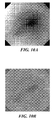
- FIG. 1 is an exemplary image of an esophagus taken with a camera comprising an exemplary scanning fiber endoscope capsule, as described below;
- FIG. 2A is a photograph of the exemplary tethered capsule endoscope (TCE) using a scanning fiber camera, which in one exemplary application, is configured to be swallowed by a patient to image the inner surface of the patient's esophagus;
- TCE tethered capsule endoscope
- FIG. 2B is a photograph illustrating the components of the tether used for the TCE of FIG. 2A , which include a single optical fiber that is used for illumination, scanner drive lines, and six plastic optical fibers that convey light received from the tissue in a body lumen;
- FIG. 2C is a photograph illustrating the relative length (and size) of the exemplary TCE, in connection with a metric ruler on which the device is positioned;
- FIG. 3 is a cut-away schematic view of the exemplary TCE showing a scanning optical fiber and other components included therein;
- FIG. 4 is a functional block diagram of an exemplary system that is used for creating mosaic images of a patient's inner esophageal surface
- FIG. 5 is a schematic diagram graphically illustrating the exemplary approach used to project a strip from the image plane onto a mosaiced pipe or cylinder, using the present technology
- FIGS. 6A , 6 B, and 6 C respectively illustrate an exemplary image of an esophagus, the image of the esophagus with a dark line to show the location of the strip that is projected to produce the mosaiced image, and the resulting strip (the notch is caused by the strip being limited by the edge of the original image);
- FIG. 7A is a photo showing an exemplary TCE system
- FIGS. 7B and 7C are respectively images of an Edmund Optics USAF 1951 test target, and a Gretag Macbeth Mini Color Chart made using the TCE;
- FIG. 7D is a mosaic image made by imaging inside a 1-inch tube of rolled paper on which a map is printed, through which the TCE was pulled slowly ( ⁇ 2 mm/sec) and kept roughly centered on its central axis, illustrating that the mosaic images are generated by the TCE system with noticeable but acceptable levels of distortion for the purpose of identifying and mapping regions of color variation;
- FIG. 8A is an exemplary mosaic image of the upper esophagus of a pig produced using the novel approach disclosed herein;
- FIG. 8B illustrates three images that show bile coated particles of food in the esophagus of the pig, as referenced in FIG. 8A ;
- FIGS. 9A , 9 B, and 9 C respectively illustrate exemplary images of a human esophagus, which were produced by the TCE system and show gastric folds (FIG. A), the important squamo-columnar junction where the stomach mucosa (red in color, but darker portion in the gray scale image) transitions to the esophageal mucosa (light pink in color or very light portion in gray scale), and another portion of the esophagus above this transition point;
- FIGS. 10A and 10B respectively illustrate images made with the TCE that show an original ( FIG. 10A ), and a neighborhood-normalized frame ( FIG. 10B ) produced from endoscopy video output from the TCE, where neighborhood normalization compensates for illumination differences between frames;
- FIGS. 11A and 11B respectively illustrate an exemplary esophagus mosaic image without gradient domain blending, and the corresponding esophagus mosaic image with gradient domain blending;
- FIG. 12A illustrates a world map as it appears on a flat sheet of paper, before being formed into a cylindrical tube that was then used to produce a video of the inner surface of the tube so that the video images could be processed by the present technique to form a mosaic image of the surface;
- FIGS. 12B and 12C respectively illustrate two exemplary input video frames of the inner surface of the world map of FIG. 12A after it was formed into a cylindrical tube;
- FIG. 12D illustrates the mosaic image produced using the present technique from the video of the world map ( FIG. 12A ) that was formed into a tube, with input video frame images like those shown in FIGS. 12B and 12C , where mixed lighting exposures evident in the mosaic image are caused by uneven lighting conditions within the tube;
- FIGS. 13A and 13B together comprise a flowchart that illustrates exemplary logical steps for producing a mosaic image from a video of a generally cylindrical surface, in accord with the present approach;
- FIG. 13C is a schematic illustration illustrating how a banded Hessian matrix used in global optimization is constructed.
- FIG. 14 is a schematic block diagram of a generally conventional personal computer (PC), which is suitable for carrying out the processing steps used to produce the mosaic image of the inner surface of a body lumen as described herein.
- PC personal computer
- FIG. 2A illustrates an exemplary TCE 16 using a scanning optical fiber as a camera
- FIG. 2B illustrates the components of a tether 18 used for the TCE of FIG.
- FIG. 2A which includes a single optical fiber that is used for illumination, scanner drive lines, and six return plastic optical fibers (not separately identified in this Figure).
- FIG. 2C illustrates the relative length or size of exemplary TCE 16 , in connection with a metric ruler 20 on which it is positioned.
- TCE and the mosaicing algorithm described below are not limited only to the esophagus, but instead, can be used for imaging any generally cylindrical body lumen, e.g., the colon.
- the optical fiber scanner is driven to scan using a 420 micron diameter piezoelectric tube to which a 4.3 mm cantilevered length of singlemode optical fiber (Nufern 460-HPTM) is affixed (see FIG. 3 ).
- the piezoelectric tube is plated with quadrant electrodes and energized with drive signals supplied through five 50 gauge wires that extend proximally through the tether.
- the piezoelectric tube, singlemode optical fiber, and an appropriate lens system are contained in a stainless steel tube having a 1.1 mm outer diameter and 13 mm length.
- a package for TCE 16 was created by encapsulating the optical fiber scanner in a smooth medical grade plastic capsule housing 22 to aid in swallowing the device.
- the capsule housing dimensions (6.35 mm ⁇ 18 mm) are those of a standard No. 2 capsule (available from Torpac Inc., Fairfield, N.J.) and were chosen over larger and smaller sizes for ease of swallowing and ability to handle, although this size should not be considered limiting, since larger or smaller capsules can instead be used, as desired.
- Six 250 micron diameter multimode optical fibers 24 are directed to a face 26 of the capsule to collect the backscattered light signal from tissue, for example, tissue comprising an internal wall of an esophagus.
- one or more optical detectors could be included in the TCE instead of the plurality of multimode optical fibers, and the signals produced by the one or more optical detectors in response to the backscattered light can be conveyed proximally through conductive leads and used for producing an image of the site.
- Wires 30 and optical fibers 24 and an optical fiber 32 that conveys the illumination light to a scanning optical fiber 34 are routed back from the capsule to the base station through thin flexible tether 18 (shown in FIG. 2B ) that is about 1.4 mm in diameter in this exemplary embodiment.
- Wires 30 are used to apply drive signals to electrical quadrants 38 formed on a patterned piezo tube 40 , which when excited by the electrical drive signal, drives scanning optical fiber 34 to move in a desired pattern (i.e., to vibrate at about its resonant frequency) relative to two generally orthogonal axes.
- Light emitted from the distal end of the moving scanning optical fiber passes through a lens assembly 42 and is focused on the tissue.
- the exemplary TCE used for testing was designed to meet the specifications shown below in Table 1.
- FIG. 4 illustrates the components of a base station 50 , which includes a red (R) laser 52 that produces light having a wavelength of about 635 nm (e.g., a FiberMaxTM, available from Blue Sky Research), a green (G) laser 54 that produces light at a wavelength of about 532 nm (e.g., a ChromalaseTM, available from Blue Sky Research), and a blue (B) laser 56 that produces light having a wavelength of about 444 nm (available from Nichia Laser Diode and OZ Optics).
- R red
- G green
- B blue
- Optical fiber combiner 58 combines the RGB light from these lasers and supplies the combined laser light to a connector 60 , which is coupled to tether 18 .
- a camera position monitor 19 monitors the position of TCE 16 by tracking the movement of tether 18 as it is drawn over and thereby rotates a wheel 21 while the TCE is being pulled through a body lumen (not shown in this Figure) by the tether.
- a scan generator signal source in this exemplary embodiment, a field programmable gate array (FPGA) board 62 generates drive signals that are applied to a piezo drive amplifier 64 .
- the amplified drive signals are supplied to connector 60 and are used to energize piezo electric tube driver 40 in the TCE.
- the base station also includes an optical fiber 66 that is coupled to a color separation system 68 (e.g., using dichroic beamsplitters).
- the color separation system separates the return light from the tissue in a patient's body lumen into separate RGB light bands and supplies these different color light signals to corresponding R, G, & B photomultiplier tube (PMT) optical detectors 70 .
- PMT photomultiplier tube
- the PMT optical detectors thus detect the three primary colors of return light conveyed through the multimode optical fibers, and the output signals from the PMT optical detectors are amplified by amplifiers 72 , producing amplified signals that are input to an image generation board (i.e., in this embodiment, another FPGA board) 74 .
- an image generation board i.e., in this embodiment, another FPGA board
- the scan generator board and the image generator board are coupled to a PCI bus 76 of a host computer (not fully indicated in this Figure), which in this exemplary embodiment, includes a WindowsTM software compatible central processor unit (CPU) 78 that is coupled to a control display 80 .
- a signal produced by cameral position monitor 19 is supplied to CPU 78 , to enable the CPU to scale the mosaiced imaged relative to the body lumen through the TCE is moved.
- the scaling of the mosaiced image relative to the position of the TCE in the body lumen enables a medical practitioner to diagnose a medical condition of tissue inside the body lumen based upon the mosaiced image, at specific points along the longitudinal axis of the body lumen.
- Image generator board 74 is also coupled to a real-time image display 82 , which displays the real-time video and can also display the mosaic image created from the video imaging of the body lumen of a patient using the technique described herein.
- Capsule shape 6.35 mm diameter, 18 mm long standard No. 2 capsule
- Capsule weight 0.6 grams housing made of polyphenylene oxide Fiber scanner 4.3 mm cantilever of 125 micron single mode optical fiber diameter
- Resonant 5 KHz amplitude modulated drive scanning Spiral scan 250 ring spiral per frame amplitude modulated sine wave and cosine waves
- Frame rate 15 Hz 30 Hz in development Objective 2.0 mm diameter window for imaging in air and lenses liquid Forward view 100 to 120 degrees maximum able to image in air and water field of view
- Depth of focus at least 45 mm axially able to image side walls of esophagus Tether diameter less than 1.5 mm smooth, soft, and supple for swallowing
- the RGB light from optical fiber combiner 58 is coupled into the core of the singlemode optical fiber that is used to supply illumination light to the TCE.
- Piezoelectric tube 40 (see FIG. 3 ) is driven with an amplitude-modulated sine wave supplied to energize selected conductive quadrants formed on the piezoelectric tube.
- the frequency of the amplitude-modulated sine wave is tuned to approximately equal the scanning fiber's first mode of mechanical resonance (currently, about 5 KHz, for this exemplary embodiment).
- Light emitted from the end of the singlemode scanning optical fiber passes through lens system 42 and is focused onto the tissue. Light reflected from the tissue is collected by multimode optical fibers 24 , routed through color separation system 68 ( FIG. 4 ), and detected by the PMT optical detectors.
- Scan generator board 62 and image generator board 74 are custom hardware boards, and each include specific FPGAs and five memory banks. The logic in these FPGAs generates and processes signals to construct the final TCE images or video.
- Florescence for imaging fluorescent light emitted by specific types of tissue and other sources
- polarization contrast for imaging light that is polarized by tissue in a specific manner
- sequential color for imaging light that is polarized by tissue in a specific manner
- the TCE system is operated by coupling the desired TCE probe into the base station comprising a personal computer (PC) (not shown in FIG. 4 —see FIG. 14 , which is described below).
- PC personal computer
- Plugged into a system bus of the PC are two custom peripheral component interconnect (PCI) electronic cards.
- the scan generator board and the image generator board are thus PCI bus cards that each contain eight analog-to-digital (A/D) converters, eight digital-to-analog (D/A) converters, five banks of parallel accessible static random access memory (SRAM) chips, and a 2-million gate FPGA (e.g., a Spartan 3TM, which available from Xilinx).
- the cards are identical except for the programming provided within the FPGA.
- One card drives the resonant scanner and is used during system calibration.
- the second card controls the laser power, constructs images from the PMT detector data signals, and drives real-time image display 82 .
- Control of the TCE system in this exemplary embodiment is implemented using a LabVIEWTM software interface (version 8.01 from National Instruments, Inc.) running on the PC.
- the user after opening the control program, the user enters the serial number of the TCE probe being used.
- the serial number identifies files stored in computer memory that contain data relating to the operation of that specific probe, such as the probe type, its resonant frequency, and drive parameters that can be applied to achieve a desired scan pattern and field-of-view for the application.
- the TCE probe parameters Once the TCE probe parameters are loaded, the TCE probe enters an imaging mode and can be used for imaging inside a lumen disposed within a patient's body.
- the TCE user interface enables a user to capture and store single image frames or a sequence of frames comprising a video or movie.
- the captured video can be used by novel mosaicing software (as described below) to create a panoramic image of the esophagus or other internal body lumen.
- Additional controls enable selective image zooming (performed by driving the resonant fiber to image with a smaller field-of-view) and laser power control. If the user desires to change performance parameters, the device can be recalibrated or again white balanced by coupling the probe to specific calibration or white balance ports, respectively, and selecting the desired function from the user interface.
- Imaging of test targets placed under the beaker commenced while current from the electrode to ground was measured using a precision multi-meter (e.g., a Tenma, Model 72-2050TM). No leakage current was detected at the detector's 200 nanoamp noise limit. Detection of any measurable leakage current above the noise floor of 0.2 microamps would cause any in vivo testing to be canceled.
- a precision multi-meter e.g., a Tenma, Model 72-2050TM.
- a capsule introducer was devised and included a flexible tube with a side slit and a custom plastic saddle at the distal tip for holding the TCE capsule. After insertion into the pig's stomach (verified by imaging), a wire was used to push forward and release the TCE capsule from the saddle. The insertion tube was withdrawn about 10 cm leaving the TCE probe within the upper stomach. Together, the TCE tether and insertion tube were slowly pulled out of the pig's esophagus, while TCE video images were recorded at the base station.
- a second TCE probe was fabricated and tested for leakage current, cleaned and sterilized with alcohol, and swallowed by a human volunteer in a sitting position. After the volunteer swallowed a few sips of water, the TCE entered the stomach and was slowly pulled back into the upper esophagus while recording video images. In total, the testing took about ten minutes for several iterations of swallowing and removal of the TCE, in this manner.
- a surface model of the esophagus To create a representation of the esophageal surface using an endoscopy video sequence, two basic elements are required: (1) a surface model of the esophagus; and, (2) a camera pose estimation for each video frame.
- the term “camera” is used to represent the function performed by the scanning fiber in the exemplary embodiment of the TCE discussed above, i.e., to form images of a generally cylindrical surface, but it should be understood that the present approach described herein for creating a representation of a generally cylindrical body lumen surface is not limited to any specific type of imaging device.
- Pose estimation is done by defining a warping function between neighboring video frames. This warping function is based on an inverse projection of one image onto the mosaicing surface followed by a projection onto another image plane.
- the warp is a function of the pose parameters of both images and the surface parameters and is used to define an intensity minimization between frames, using the framework of Lucas-Kanade alignment.
- Each image is compared to at least its two neighbors in the sequence, but this technique results in two (likely inconsistent) pose estimations for each frame.
- the series of duplicate pose estimations are not readily combined into a single camera path, so the registration is done as a global minimization across all frames.
- FIG. 11A shows an exemplary esophageal mosaic image without gradient blending applied
- FIG. 11B shows the mosaic image with gradient blending, to illustrate the benefit of performing this blending step.
- This mosaicing technique is most closely related to a prior art technique developed by Rousso et al., who introduced the idea of a pipe projection that allows the mosaicing of video containing forward motion.
- the pipe projection transforms radial optical flow into parallel optical flow lines, enabling projected images to be stitched via a simple shift.
- the viewing pipe in this earlier approach does not necessarily correspond to the physical lumen in a patient's body.
- the viewing pipe in Rousso et al. is defined by placing the camera's optical center and the focus of expansion on the pipe's central axis, which would certainly not be the case for an entire video sequence of a physical lumen.
- the pipe mosaicing algorithm might produce a mosaic where the input images are stitched together seamlessly, but it would likely significantly distort the interior surface of the lumen in the resulting mosaic image. If a camera is moved straight down a lumen, but is off center, for example, the side closer to the camera will be magnified relative to the other side.
- Pipe projection enables sequences exhibiting forward motion to be mosaiced by transforming radial optical flow into parallel optical flow in the projected image.
- the mosaicing approach that is used should enable mosaicing on the surface of the physical lumen, and not use a pipe as a manifold to transform optical flow.
- the input to the algorithm used for the present exemplary approach is a set of perspective views from a camera moving within a known type of surface, such as a cylinder. From this sequence, the 6 degrees-of-freedom (DOF) camera pose for each frame is estimated, and optionally, parameters describing the surface shape are estimated, if they are not fully known. For a known pose, each frame is projected onto the surface, which can be displayed as a flat image constituting the mosaic image. Pose estimation is done by defining a warping function between successive video frames. This warp is based on the step of projecting one frame onto the mosaicing surface and taking a virtual view from the location of the template frame; it is a function of the pose parameters of both frames and the surface parameters.
- DOF degrees-of-freedom
- This warp is used to define an intensity minimization between frames, which is a well studied problem.
- the Lucas-Kanade algorithm is used to solve for the warp between two frames, giving the pose of each.
- To compute a consistent set of warps across all frames the process solves for all of the warps between successive frames globally; the computation of a consistent pose estimate for each frame tends to be much more stable than pair wise estimates.
- Once the camera poses are known, generating the mosaic is just a problem of selecting the appropriate patches from each frame so as to get the best resolution and produce a seamless composite mosaic image.
- the image warp to be solved for is modeled as a combination of a perspective projection from one camera location onto a mosaic surface, followed by an inverse projection to another camera location.
- the quantity R xyz u is the direction from the optical center to the 3-D pixel location, adjusted to the coordinate system of the surface.
- the warp is defined such that the intersection with the smallest positive c is used if there are multiple ray-surface intersections.
- An image can now be projected onto the surface from one pose and a virtual view can be made from another pose.
- a Lucas-Kanade style forwards additive approach is employed to achieve this result, as is known in the art.
- the forwards additive algorithm is computationally more expensive than the alternatives, but since the set of warps does not generally form a semi-group or group, the other compositional algorithms aren't applicable. Furthermore, the requirements for inverse additive approach are not satisfied. Given a current estimate of X 1 and X 2 , the goal is to find iterative updates ⁇ X 1 and ⁇ X 2 that reduce the error function
- the warping function is the combination of two projections, so the Jacobian of the warp can be expressed in terms of the Jacobians of the projections
- ⁇ W ⁇ ( X 1 , X 2 ) [ ⁇ P - 1 ⁇ a ⁇ ⁇ P ⁇ X 1 ⁇ P - 1 ⁇ X 2 ] .
- the surface function it is necessary that the surface function be differentiable. Depending on the surface type, deriving the Jacobian can become quite a long process, although not necessarily complex.
- the pose parameters are initialized based on the generally cylindrical surface of a body lumen, and the camera is expected to be oriented axially, facing directly down the lumen. All frames are given the same initial pose.
- the iterative update can be run on a coarse-to-fine basis to handle motion greater than one pixel and for computational improvement. When transitioning from a coarser to a finer iteration, the positional pose parameters need to be scaled along with the surface, but the orientation parameters should not be.
- the algorithm outlined above will estimate the pose of two images, but when dealing with an entire video sequence, the pose of every frame is of interest.
- a common approach is to align pairs of frames sequentially, but this does not work in this case because the warping parameters are not independent.
- a sequential registration would likely produce two different pose estimates for each frame, one from the warp to the previous frame, and one from the warp to the next.
- the pair wise optimizations are reformulated into one global optimization that minimizes the error between successive frames simultaneously.
- the error function that is to be minimized is a sum of the pair wise error
- the Jacobian is mostly empty, only containing nonzero entries for only the pose parameters affecting that warp.
- the Hessian for the global optimization is a 6n ⁇ 6n square matrix. However, since only consecutive frames are compared, the Hessian is sparse and banded, enabling this problem to be solved efficiently.
- the global Hessian and residual can be constructed from their pair wise counterparts, as is illustrated in FIG. 13C . As indicated in this Figure, the banded Hessian matrix is constructed from Hessians of the pair wise registration, and overlapping regions are summed.
- Information obtained from sources besides optical flow can be incorporated into the registration algorithm to improve performance. Pixels can be weighted or ignored based on a quality measure, such as the camera's signal-to-noise ratio. This step can be done independently in each color channel, providing better registration if a particular color channel is noisy. Additionally, the algorithm can ignore entire video frames if they are deemed to be of poor quality. These alterations can be done as a preprocessing step, or can be carried out in real time as the program runs.
- this information can also be used to constrain the registration.
- the general formulation of the registration algorithm enables the pose parameters of neighboring frames to be arbitrarily different. Since the video or sequence of images is known to be taken from a tethered camera, the motion can be assumed to be much less chaotic.
- the iterative updates can be weighted to give preference to a family of know trajectories, yielding a stability and performance improvement.
- the position of the camera within a body lumen can be determined by monitoring the tether as the camera is pulled through the body lumen, as the video sequence is being captured.
- the mosaiced image that is produced can be thus be scaled to the body lumen, enabling medical personnel to determine specific positions in the body lumen, e.g., where diseased conditions of the tissue are evident in the mosaiced image.
- An automatic monitor such as camera position monitor 19 ( FIG. 4 ) can be provided to track the movement of the tether and thus the position of the camera within the body lumen, as the camera is moved through the body lumen to capture the video sequence.
- Strips 106 used to make the mosaic are determined by a “scanning broom.”
- An exemplary internal surface image 110 is shown in FIG. 6A .
- Any line 112 selected in the video frame will “sweep” over the scene (thus, the term “scanning broom”) as the video is played (see FIG. 6B ).
- the shape of this scanning broom depends on the motion in the scene, ideally being perpendicular to the optical flow. In the case of forward motion, the shape is an ellipse centered around the focus of expansion.
- Strips 114 (an example of one strip is shown in FIG. 6C ) are defined implicitly based on knowledge of a camera position (depth in the pipe) for each frame or image.
- An elliptical scan line in the frame is defined implicitly by selecting a distance down the pipe from a given frame's center of projection. After determining the change in depth for a particular frame, this value is added to the chosen distance to define another line in the frame. The area between these two lines is the strip to be added to the mosaic. Occasionally, the elliptical strip will stray outside of the frame boundaries, which is addressed by simply leaving the corresponding areas of the mosaic to be filled in by subsequent frames. These areas are guaranteed to come into view, because the camera is moving backward. As a result, the sampling strip appears to hug the edge of the frame when the strip would otherwise extend out of frame.
- the alignment method that is used relies on a few assumptions, notably, constant lighting, small motions, and smooth gradients.
- the small-motion issue is addressed with course-to-fine alignment and the smoothness problem can easily be fixed by blurring the images.
- Constant illumination is an issue because the light source is on the camera itself in this exemplary embodiment, so lighting changes as the camera moves.
- neighborhood normalization the mean intensity and standard deviation are computed for a small window around each pixel. By subtracting the mean from the pixel value and dividing by the standard deviation, some measure of a point's actual color independent of the lighting conditions is obtained. The resulting image can then be used for the pair wise alignment, satisfying the color-constancy assumption.
- FIG. 10A illustrates an exemplary original image of an esophagus
- FIG. 10B illustrates a neighborhood-normalized frame, where both images were derived from endoscopy video. Neighborhood normalization allows compensation for illumination differences between frames.
- Imperfect alignment and changing illumination result in noticeable seams along the strip boundaries. It is preferable to minimize these seams without removing any details from the image.
- a simple blending approach like feathering, usually requires a large overlap with good registration to avoid ghosting, but in the present case, the registration is only likely to be good in a small region along the seam. Instead, gradient domain blending is used.
- the completed TCE system (base station and probe) meet all design criteria listed in Table 1 and this system is shown in FIGS. 2A , 2 B (TCE probe and tether), and 7 A (which illustrates the full system).
- the measured total laser power at maximum power setting is about 1.5 mW (B-442 nm), 2.3 mW (G-532 nm), and 3.6 mW (R-635 nm) for the color components, as measured using an optical power meter and probe (Newport 1830-CTM and 818-STTM).
- the maximum TCE optical power is 3 ⁇ less than mid-range illumination, and 40 ⁇ less than full-power illumination when measurements are made at a 532 nm responsivity of the silicon sensor.
- flat test targets e.g., the Gretag Macbeth Mini Color Chart shown in FIG. 7C and Edmund Optics USAF 1951 test target shown in FIG. 7B
- Target number 3-3 has a 49.0 micron bar width which can be resolved in the peripheral field of FIG. 7B .
- the TCE probe for animal testing measured just over 100 degrees FOV, while the TCE probe for human testing measured just below 100°.
- FIG. 12D Another exemplary mosaic shown in FIG. 12D was created for a world map image.
- the paper on which the world map was imprinted was rolled to form a 10 inch diameter, 5 ft. long tube lined with the rolled world map, which is shown in FIG. 12A before being formed into the cylindrical tube.
- the camera was inserted into the tube on a plastic tray (not separately shown).
- the video was taken with a consumer camcorder (not separately shown—as an example that employs a different type of camera than the exemplary TCE described herein).
- the scene was unevenly lit, as is apparent in the exemplary input video image frames shown in FIGS. 12B and 12C . Along with a limited depth of field, these issues made the registration challenging.
- FIG. 12D is constructed from strips taken from 400 such video frame images.
- the bottom of the map is cut off in this mosaic image, since the bottom of the world map was not visible on the inner surface of the map after being rolled to form the cylindrical tube.
- the mixed exposure evident in the mosaic image of FIG. 12D was caused by uneven lighting conditions within the cylindrical tube.
- the mosaic image produced using the 6 DOF algorithm closely matches the reference image of FIG. 12A , demonstrating the algorithm's capability for metric accuracy.
- TCE testing within the live pig revealed images of the lower esophagus to mouth with a mosaic image of the upper esophagus, shown in FIG. 8A , which was produced from images of the upper esophagus shown in FIG. 8B .
- Bright yellow-green bile was present in the pig stomach and particles 120 of bile-coated food appeared on the esophagus walls during imaging of the pig in the supine position.
- Suction applied to a secondary tube alongside the TCE removed much of the obscuring bile.
- the human volunteer In a sitting position, the human volunteer easily swallowed the TCE probe using only sips of water and taking several swallows.
- the TCE probe revealed a clear image of the gastric folds as shown in FIG.
- FIG. 9A An image of the mid-esophagus region is shown in FIG. 9C .
- the red TCE illumination was reduced from the maximum in order to match the expected hues per the recommendations of two observing gastroenterologists.
- TCE images shown in FIGS. 9A , 9 B, and 9 C were increased in brightness and contrast by 10-20% using photo enhancement software. Occasionally bubbles obscured the esophagus walls. The bubbles were removed from the FOV by draining the residual water, by swallowing, or by adding additional water.
- a flowchart 300 in FIG. 13A illustrates the steps of exemplary logic that are used to produce a mosaic image of an internal surface of a body lumen in accord with the present technique. Details of each of these steps are otherwise discussed herein.
- a step 302 provides for solving for six degrees-of-freedom camera pose parameters p for a video sequence produced by the camera use in the TCE probe. These parameters are determined by iterative minimization so as to minimize an error function, which is itself, a function of the 2-D images produced by the camera, a projection on the scene geometry, and an inverse projection. Details of the iterative steps follow.
- a step 304 computes local Hessian, A 1 -A n ⁇ 1 and the residual for consecutive video frames (or images), e.g., as shown in FIG.
- each 12 ⁇ 12 matrix A i is added to the submatrix A[6i ⁇ 5, . . . , 6i+6; 6i ⁇ 5, . . . , 6i+6].
- each 12 ⁇ 1 matrix B i is added to the submatrix A[6i ⁇ 5, . . . , 6i+6; 1].
- a decision step 314 determines if p changed and if so, the logic repeats, starting with step 304 . Otherwise, the logic continues with a step 316 ( FIG.
- each image I i is warped with a defined function W ⁇ 1 (W(x;p i+1 );p i ), to compute I i (W ⁇ 1 (X;p i ⁇ 1 );p i )).
- error images are computed in a step 318 , and a step 320 computes the Jacobian of the warping function.
- a step 322 computes the image gradient, and a step 324 evaluates the Jacobian of the image warp.
- the Hessian is evaluated, and a step 328 evaluates the residual, b i .
- TCE swallowability and imaging performance met all expectations in this first-generation prototype.
- the capsule was easily swallowed with no side effects.
- a capsule weighing approximately 150% more may aid in more rapid peristaltic movement into the stomach.
- simethicone can be used to reduce bubbles. Because most of the capsule is empty space, adding weight is a minor modification.
- the mosaic algorithm successfully captures the esophageal surface. Most of the seaming artifacts occur when the camera changes direction or pauses for an extended period of time, but are undetectable after gradient domain blending. Lighting inconsistencies in the input image cause artifacts in the mosaic, which are especially noticeable when the sampling strip covers a specular reflection. Color consistency within the mosaic should improve as the automatic gain control is made more sophisticated, for example, by using gamma correction.
- the TCE prototype has one major difference from conventional all camera-based capsule endoscopes, specifically, the versatility of adding advanced imaging features and laser diagnostics while not affecting the size or cost of the TCE probe.
- magnification endoscopy can be added as a feature.
- narrow band imaging within the visible spectrum can be displayed concurrently with combined RGB imaging.
- a post-processing algorithm can be used to enhance color differences within the mosaic image beyond the visible spectrum, using light sources across the ultraviolet to infrared spectrum.
- fluorescence imaging i.e., to produce images responsive to fluorescent light from tissue
- fluorescence imaging i.e., to produce images responsive to fluorescent light from tissue
- the clinical value and specific role of the TCE image mosaicing feature has yet to be determined. Possible uses are to provide: (1) a color printout of the endoscopy for patient-doctor counseling; (2) a scaled mapping of the regions of BE to more rapidly assist in determining between long segments, short segments, and tongues of BE; (3) a single fused image that combines the results from multiple TCE mosaics from multiple swallowings to reduce ambiguity from a single imaging pass; (4) the ability to map regions of non-visible multimodal image data overlaid in pseudo-color and possibly select biopsy sites; (5) the ability to add quantitative optical biopsy measures based on laser-induced fluorescence and spectroscopy; and, (6) a visual record of the patient's medical history, which also combines multiple sensor data such as pH and sphincter pressure.
- the mosaic image is generated with less than 5 minutes of post processing of the TCE images, while real-time mosaicing is expected by using graphic processor chips in the future.
- a tether position sensor is needed, as previously developed for the BE colorimetry probe.
- FIG. 14 illustrates an exemplary computing system 1100 that is suitable for use as a computing device employed for implementing the novel approach described above.
- Computing system 1100 includes a processor 1112 that is coupled in communication with a generally conventional data bus 1114 . Also coupled to the data bus are a memory 1116 that includes both random access memory (RAM) and read only memory (ROM).
- RAM random access memory
- ROM read only memory
- Machine instructions are loaded into memory 1116 from storage on a hard drive 1118 or from other suitable non-volatile memory, such as an optical disk or other optical or magnetic storage media.
- the storage can also include files that define the images taken by an endoscope camera.
- the machine instructions in storage when transferred to memory 1116 and executed by processor 1112 , can cause the processor to carry out a plurality of different functions employed to implement the novel approach, as described herein, as well as other functions.
- An input/output (I/O) interface 1120 that includes a plurality of different types of ports, such as serial, parallel, universal serial bus, PS/2, and Firewire ports, is coupled to data bus 1114 and is in turn connected to one or more input devices 1124 , such as a keyboard, mouse, or other pointing device, enabling a user to interact with the computing system and to provide input and control the operation of the computing system.
- a display interface 1122 couples a display device 1126 to the data bus, enabling graphic and text information to be displayed for viewing by a user.
- a camera or imaging system 1132 is coupled to I/O interface 1120 to convey the signal produced by the camera into the computing system.
- the computing system is also optionally coupled to a network 1130 and/or to the Internet via a network interface 1128 , which couples to data bus 1114 .
Abstract
Description
| TABLE 1 | ||
| Attribute | Value | Comment |
| Capsule shape | 6.35 mm diameter, 18 mm long | standard No. 2 capsule |
| Capsule weight | 0.6 grams | housing made of polyphenylene |
| oxide | ||
| Fiber scanner | 4.3 mm cantilever of 125 micron | single mode optical fiber |
| diameter | ||
| Resonant | 5 KHz | amplitude modulated drive |
| scanning | ||
| Spiral scan | 250 ring spiral per frame | amplitude modulated sine wave and |
| cosine waves | ||
| Frame rate | 15 Hz | 30 Hz in development |
| Objective | 2.0 mm diameter | window for imaging in air and |
| lenses | liquid | |
| Forward view | 100 to 120 degrees maximum | able to image in air and water |
| field of view | ||
| Image | 500 pixels across image | spatial resolution of <100 microns |
| resolution | ||
| Depth of focus | at least 45 mm axially | able to image side walls of |
| esophagus | ||
| Tether diameter | less than 1.5 mm | smooth, soft, and supple for |
| swallowing | ||
S=x+R xyz uc
where x=(x, y, z) is the position of the camera, Rxyz=Rx(α)Ry(β)Rz(γ) is the rotation matrix representing the camera's orientation, and c is the scale factor required to intersect the projective surface. The quantity Rxyzu is the direction from the optical center to the 3-D pixel location, adjusted to the coordinate system of the surface.
where X=(x,y,z,α,β,γ) contains the six-degree-of-freedom camera pose. The warp is defined such that the intersection with the smallest positive c is used if there are multiple ray-surface intersections.
u=R xyz −1(S−x)/c
it is possible to easily find c and thus, achieve the inverse projection
W(u,X 1 ,X 2)=P −1(P(u,X 1),X 2).
and the relation between surface coordinate and image coordinate becomes
r 2=(r cos(α))2+(r sin(α))2=(c(Ru)x +x)2+(c(Ru)y +y)2.
α=arctan((y+P y c)/(x+P x)) and k=z+(Ru)z c.
Pair Wise Pose Estimation
where H is the Hessian
and b is the residual
In order to compute the Jacobian, it is necessary that the surface function be differentiable. Depending on the surface type, deriving the Jacobian can become quite a long process, although not necessarily complex.
The process continues with deriving the Jacobian for the warp between frame i and i+1,
the Hessian
and the residual,
The iterative update becomes
W(u,X 1 ,X 2 ,s)=P −1(P(u,X 1 ,s),X 2 ,s).
The surface parameters are treated just like the pose parameters, resulting in the Jacobian for the warp between frame i and i+1.
The iterative update scheme becomes
where the Hessian and residual are defined just as before. Examples of this extension include an elliptical cylinder with unknown relative semi-major and semi-minor axes, or any other surface that varies by being stretched in one dimension.
Additional Information
Mv=w,
where M is a sparse matrix containing two rows for each pixel (minus the boundary cases). A least-squares fit can be found by multiplying both sides by MT. The matrix MTM gives the Laplacian of an image when represented in vector form, so in essence, the image is derived from its associated Laplacian.
Results
Claims (27)
Priority Applications (1)
| Application Number | Priority Date | Filing Date | Title |
|---|---|---|---|
| US11/749,959 US7813538B2 (en) | 2007-04-17 | 2007-05-17 | Shadowing pipe mosaicing algorithms with application to esophageal endoscopy |
Applications Claiming Priority (2)
| Application Number | Priority Date | Filing Date | Title |
|---|---|---|---|
| US91223707P | 2007-04-17 | 2007-04-17 | |
| US11/749,959 US7813538B2 (en) | 2007-04-17 | 2007-05-17 | Shadowing pipe mosaicing algorithms with application to esophageal endoscopy |
Publications (2)
| Publication Number | Publication Date |
|---|---|
| US20080262312A1 US20080262312A1 (en) | 2008-10-23 |
| US7813538B2 true US7813538B2 (en) | 2010-10-12 |
Family
ID=39872931
Family Applications (1)
| Application Number | Title | Priority Date | Filing Date |
|---|---|---|---|
| US11/749,959 Active 2029-08-11 US7813538B2 (en) | 2007-04-17 | 2007-05-17 | Shadowing pipe mosaicing algorithms with application to esophageal endoscopy |
Country Status (1)
| Country | Link |
|---|---|
| US (1) | US7813538B2 (en) |
Cited By (24)
| Publication number | Priority date | Publication date | Assignee | Title |
|---|---|---|---|---|
| US20080166072A1 (en) * | 2007-01-09 | 2008-07-10 | Kang-Huai Wang | Methods to compensate manufacturing variations and design imperfections in a capsule camera |
| US20080165248A1 (en) * | 2007-01-09 | 2008-07-10 | Capso Vision, Inc. | Methods to compensate manufacturing variations and design imperfections in a capsule camera |
| US20090161097A1 (en) * | 2007-12-19 | 2009-06-25 | Vistec Semiconductor Systems Gmbh | Method for optical inspection, detection and visualization of defects on disk-shaped Objects |
| US20090208071A1 (en) * | 2005-02-15 | 2009-08-20 | Olympus Corporation | Medical Image Processing Apparatus, Luminal Image Processing Apparatus, Luminal Image Processing Method, and Programs for the Same |
| WO2012173976A3 (en) * | 2011-06-17 | 2014-05-08 | Carroll Robert G | Methods and apparatus for assessing activity of an organ and uses thereof |
| US20150016700A1 (en) * | 2012-01-31 | 2015-01-15 | Given Imaging Ltd. | System and method for displaying motility events in an in vivo image stream |
| US20150097961A1 (en) * | 2013-08-09 | 2015-04-09 | Russell URE | System, Method and Apparatus for Remote Monitoring |
| US20150208904A1 (en) * | 2014-01-30 | 2015-07-30 | Woon Jong Yoon | Image-based feedback endoscopy system |
| US9107578B2 (en) | 2013-03-31 | 2015-08-18 | Gyrus Acmi, Inc. | Panoramic organ imaging |
| CN105263387A (en) * | 2013-06-03 | 2016-01-20 | 奥林巴斯株式会社 | Scanning endoscope |
| US9509917B2 (en) | 2012-07-26 | 2016-11-29 | DePuy Synthes Products, Inc. | Wide dynamic range using monochromatic sensor |
| US9516239B2 (en) | 2012-07-26 | 2016-12-06 | DePuy Synthes Products, Inc. | YCBCR pulsed illumination scheme in a light deficient environment |
| US9641815B2 (en) | 2013-03-15 | 2017-05-02 | DePuy Synthes Products, Inc. | Super resolution and color motion artifact correction in a pulsed color imaging system |
| US9655501B2 (en) | 2013-06-25 | 2017-05-23 | Digital Direct Ir, Inc. | Side-scan infrared imaging devices |
| US9777913B2 (en) | 2013-03-15 | 2017-10-03 | DePuy Synthes Products, Inc. | Controlling the integral light energy of a laser pulse |
| US10084944B2 (en) | 2014-03-21 | 2018-09-25 | DePuy Synthes Products, Inc. | Card edge connector for an imaging sensor |
| US10251530B2 (en) | 2013-03-15 | 2019-04-09 | DePuy Synthes Products, Inc. | Scope sensing in a light controlled environment |
| US10341588B2 (en) | 2013-03-15 | 2019-07-02 | DePuy Synthes Products, Inc. | Noise aware edge enhancement |
| US10341593B2 (en) | 2013-03-15 | 2019-07-02 | DePuy Synthes Products, Inc. | Comprehensive fixed pattern noise cancellation |
| US10499029B2 (en) | 2007-01-09 | 2019-12-03 | Capso Vision Inc | Methods to compensate manufacturing variations and design imperfections in a display device |
| US10568496B2 (en) | 2012-07-26 | 2020-02-25 | DePuy Synthes Products, Inc. | Continuous video in a light deficient environment |
| WO2021061335A1 (en) * | 2019-09-23 | 2021-04-01 | Boston Scientific Scimed, Inc. | System and method for endoscopic video enhancement, quantitation and surgical guidance |
| US11047671B1 (en) | 2020-01-30 | 2021-06-29 | Veravanti Inc. | Forward looking RGB/optical coherence tomography duplex imager |
| US20210307689A1 (en) * | 2016-06-16 | 2021-10-07 | Circa Scientific, Inc. | Esophageal monitoring |
Families Citing this family (122)
| Publication number | Priority date | Publication date | Assignee | Title |
|---|---|---|---|---|
| US9125552B2 (en) * | 2007-07-31 | 2015-09-08 | Ethicon Endo-Surgery, Inc. | Optical scanning module and means for attaching the module to medical instruments for introducing the module into the anatomy |
| US20090074265A1 (en) * | 2007-09-17 | 2009-03-19 | Capsovision Inc. | Imaging review and navigation workstation system |
| US8269825B1 (en) * | 2007-10-04 | 2012-09-18 | Dupaco, Inc. | Video observation of a patient's face during a medical procedure while the patient is in a prone position |
| US8542748B2 (en) | 2008-03-28 | 2013-09-24 | Sharp Laboratories Of America, Inc. | Methods and systems for parallel video encoding and decoding |
| US8062316B2 (en) | 2008-04-23 | 2011-11-22 | Avinger, Inc. | Catheter system and method for boring through blocked vascular passages |
| US9125562B2 (en) | 2009-07-01 | 2015-09-08 | Avinger, Inc. | Catheter-based off-axis optical coherence tomography imaging system |
| US8548571B2 (en) | 2009-12-08 | 2013-10-01 | Avinger, Inc. | Devices and methods for predicting and preventing restenosis |
| CN101897189B (en) * | 2008-10-10 | 2016-07-06 | 松下电器产业株式会社 | Picture decoding apparatus and picture decoding method |
| US8337397B2 (en) | 2009-03-26 | 2012-12-25 | Intuitive Surgical Operations, Inc. | Method and system for providing visual guidance to an operator for steering a tip of an endoscopic device toward one or more landmarks in a patient |
| US10004387B2 (en) * | 2009-03-26 | 2018-06-26 | Intuitive Surgical Operations, Inc. | Method and system for assisting an operator in endoscopic navigation |
| CN105596005B (en) * | 2009-03-26 | 2019-01-22 | 直观外科手术操作公司 | System for endoscope navigation |
| WO2010129075A1 (en) | 2009-04-28 | 2010-11-11 | Avinger, Inc. | Guidewire support catheter |
| JP2010253156A (en) * | 2009-04-28 | 2010-11-11 | Fujifilm Corp | Endoscope system, endoscope, and endoscope driving method |
| EP2424422B1 (en) * | 2009-04-29 | 2019-08-14 | Koninklijke Philips N.V. | Real-time depth estimation from monocular endoscope images |
| CA2763324C (en) | 2009-05-28 | 2018-10-23 | Avinger, Inc. | Optical coherence tomography for biological imaging |
| JP2010284369A (en) * | 2009-06-12 | 2010-12-24 | Fujifilm Corp | Endoscope system, endoscope, and endoscope driving method |
| US11278190B2 (en) | 2009-06-18 | 2022-03-22 | Endochoice, Inc. | Multi-viewing element endoscope |
| US9713417B2 (en) | 2009-06-18 | 2017-07-25 | Endochoice, Inc. | Image capture assembly for use in a multi-viewing elements endoscope |
| US10524645B2 (en) | 2009-06-18 | 2020-01-07 | Endochoice, Inc. | Method and system for eliminating image motion blur in a multiple viewing elements endoscope |
| US9101268B2 (en) | 2009-06-18 | 2015-08-11 | Endochoice Innovation Center Ltd. | Multi-camera endoscope |
| US9474440B2 (en) | 2009-06-18 | 2016-10-25 | Endochoice, Inc. | Endoscope tip position visual indicator and heat management system |
| US11864734B2 (en) | 2009-06-18 | 2024-01-09 | Endochoice, Inc. | Multi-camera endoscope |
| US9872609B2 (en) | 2009-06-18 | 2018-01-23 | Endochoice Innovation Center Ltd. | Multi-camera endoscope |
| US11547275B2 (en) | 2009-06-18 | 2023-01-10 | Endochoice, Inc. | Compact multi-viewing element endoscope system |
| US9402533B2 (en) | 2011-03-07 | 2016-08-02 | Endochoice Innovation Center Ltd. | Endoscope circuit board assembly |
| US9492063B2 (en) | 2009-06-18 | 2016-11-15 | Endochoice Innovation Center Ltd. | Multi-viewing element endoscope |
| US8926502B2 (en) | 2011-03-07 | 2015-01-06 | Endochoice, Inc. | Multi camera endoscope having a side service channel |
| WO2012038958A2 (en) | 2010-09-20 | 2012-03-29 | Peermedical Ltd. | Multi-camera endoscope having fluid channels |
| US9554692B2 (en) * | 2009-06-18 | 2017-01-31 | EndoChoice Innovation Ctr. Ltd. | Multi-camera endoscope |
| US9706903B2 (en) | 2009-06-18 | 2017-07-18 | Endochoice, Inc. | Multiple viewing elements endoscope system with modular imaging units |
| US10130246B2 (en) | 2009-06-18 | 2018-11-20 | Endochoice, Inc. | Systems and methods for regulating temperature and illumination intensity at the distal tip of an endoscope |
| US9101287B2 (en) | 2011-03-07 | 2015-08-11 | Endochoice Innovation Center Ltd. | Multi camera endoscope assembly having multiple working channels |
| US9901244B2 (en) | 2009-06-18 | 2018-02-27 | Endochoice, Inc. | Circuit board assembly of a multiple viewing elements endoscope |
| WO2012120507A1 (en) | 2011-02-07 | 2012-09-13 | Peermedical Ltd. | Multi-element cover for a multi-camera endoscope |
| US9642513B2 (en) | 2009-06-18 | 2017-05-09 | Endochoice Inc. | Compact multi-viewing element endoscope system |
| US10165929B2 (en) | 2009-06-18 | 2019-01-01 | Endochoice, Inc. | Compact multi-viewing element endoscope system |
| EP2448502B1 (en) | 2009-07-01 | 2022-04-06 | Avinger, Inc. | Atherectomy catheter with laterally-displaceable tip |
| JP2013531542A (en) | 2010-07-01 | 2013-08-08 | アビンガー・インコーポレイテッド | An atherectomy catheter having a longitudinally movable drive shaft |
| WO2014039099A1 (en) | 2012-09-06 | 2014-03-13 | Avinger, Inc. | Balloon atherectomy catheters with imaging |
| US11382653B2 (en) | 2010-07-01 | 2022-07-12 | Avinger, Inc. | Atherectomy catheter |
| WO2014039096A1 (en) | 2012-09-06 | 2014-03-13 | Avinger, Inc. | Re-entry stylet for catheter |
| US20120008686A1 (en) * | 2010-07-06 | 2012-01-12 | Apple Inc. | Motion compensation using vector quantized interpolation filters |
| US20120014431A1 (en) * | 2010-07-14 | 2012-01-19 | Jie Zhao | Methods and Systems for Parallel Video Encoding and Parallel Video Decoding |
| US9560953B2 (en) | 2010-09-20 | 2017-02-07 | Endochoice, Inc. | Operational interface in a multi-viewing element endoscope |
| US9628821B2 (en) | 2010-10-01 | 2017-04-18 | Apple Inc. | Motion compensation using decoder-defined vector quantized interpolation filters |
| US9313514B2 (en) | 2010-10-01 | 2016-04-12 | Sharp Kabushiki Kaisha | Methods and systems for entropy coder initialization |
| US10663714B2 (en) | 2010-10-28 | 2020-05-26 | Endochoice, Inc. | Optical system for an endoscope |
| US9706908B2 (en) | 2010-10-28 | 2017-07-18 | Endochoice, Inc. | Image capture and video processing systems and methods for multiple viewing element endoscopes |
| CN103403605A (en) | 2010-10-28 | 2013-11-20 | 恩多巧爱思创新中心有限公司 | Optical systems for multi-sensor endoscopes |
| US11889986B2 (en) | 2010-12-09 | 2024-02-06 | Endochoice, Inc. | Flexible electronic circuit board for a multi-camera endoscope |
| US9814374B2 (en) | 2010-12-09 | 2017-11-14 | Endochoice Innovation Center Ltd. | Flexible electronic circuit board for a multi-camera endoscope |
| EP2648602B1 (en) | 2010-12-09 | 2018-07-18 | EndoChoice Innovation Center Ltd. | Flexible electronic circuit board multi-camera endoscope |
| US10517464B2 (en) | 2011-02-07 | 2019-12-31 | Endochoice, Inc. | Multi-element cover for a multi-camera endoscope |
| WO2012145133A2 (en) | 2011-03-28 | 2012-10-26 | Avinger, Inc. | Occlusion-crossing devices, imaging, and atherectomy devices |
| US9949754B2 (en) | 2011-03-28 | 2018-04-24 | Avinger, Inc. | Occlusion-crossing devices |
| DE102011076928A1 (en) * | 2011-06-03 | 2012-12-06 | Siemens Ag | Method and device for carrying out an examination of a body cavity of a patient |
| JP6112624B2 (en) | 2011-08-02 | 2017-04-12 | ビューズアイキュー インコーポレイテッドViewsIQ Inc. | Apparatus and method for digital microscope imaging |
| WO2013059363A1 (en) | 2011-10-17 | 2013-04-25 | Avinger, Inc. | Atherectomy catheters and non-contact actuation mechanism for catheters |
| US9345406B2 (en) | 2011-11-11 | 2016-05-24 | Avinger, Inc. | Occlusion-crossing devices, atherectomy devices, and imaging |
| EP2604172B1 (en) | 2011-12-13 | 2015-08-12 | EndoChoice Innovation Center Ltd. | Rotatable connector for an endoscope |
| EP2604175B1 (en) | 2011-12-13 | 2019-11-20 | EndoChoice Innovation Center Ltd. | Removable tip endoscope |
| EP2849661B1 (en) | 2012-05-14 | 2020-12-09 | Avinger, Inc. | Atherectomy catheters with imaging |
| EP2849660B1 (en) | 2012-05-14 | 2021-08-25 | Avinger, Inc. | Atherectomy catheter drive assemblies |
| EP2849636B1 (en) | 2012-05-14 | 2020-04-22 | Avinger, Inc. | Optical coherence tomography with graded index fiber for biological imaging |
| WO2013177154A1 (en) * | 2012-05-21 | 2013-11-28 | The General Hospital Corporation | Apparatus, device and method for capsule microscopy |
| CN103544688B (en) * | 2012-07-11 | 2018-06-29 | 东芝医疗系统株式会社 | Medical imaging fusing device and method |
| US9560954B2 (en) | 2012-07-24 | 2017-02-07 | Endochoice, Inc. | Connector for use with endoscope |
| US9498247B2 (en) | 2014-02-06 | 2016-11-22 | Avinger, Inc. | Atherectomy catheters and occlusion crossing devices |
| US11284916B2 (en) | 2012-09-06 | 2022-03-29 | Avinger, Inc. | Atherectomy catheters and occlusion crossing devices |
| US11179028B2 (en) * | 2013-02-01 | 2021-11-23 | The General Hospital Corporation | Objective lens arrangement for confocal endomicroscopy |
| US20140240477A1 (en) * | 2013-02-26 | 2014-08-28 | Qualcomm Incorporated | Multi-spectral imaging system for shadow detection and attenuation |
| US11096717B2 (en) | 2013-03-15 | 2021-08-24 | Avinger, Inc. | Tissue collection device for catheter |
| WO2014143064A1 (en) | 2013-03-15 | 2014-09-18 | Avinger, Inc. | Chronic total occlusion crossing devices with imaging |
| US10932670B2 (en) | 2013-03-15 | 2021-03-02 | Avinger, Inc. | Optical pressure sensor assembly |
| US9993142B2 (en) | 2013-03-28 | 2018-06-12 | Endochoice, Inc. | Fluid distribution device for a multiple viewing elements endoscope |
| US10595714B2 (en) | 2013-03-28 | 2020-03-24 | Endochoice, Inc. | Multi-jet controller for an endoscope |
| US9986899B2 (en) | 2013-03-28 | 2018-06-05 | Endochoice, Inc. | Manifold for a multiple viewing elements endoscope |
| US9636003B2 (en) | 2013-06-28 | 2017-05-02 | Endochoice, Inc. | Multi-jet distributor for an endoscope |
| EP2994034B1 (en) | 2013-05-07 | 2020-09-16 | EndoChoice, Inc. | White balance enclosure for use with a multi-viewing elements endoscope |
| US10499794B2 (en) | 2013-05-09 | 2019-12-10 | Endochoice, Inc. | Operational interface in a multi-viewing element endoscope |
| US9949623B2 (en) | 2013-05-17 | 2018-04-24 | Endochoice, Inc. | Endoscope control unit with braking system |
| JP6173035B2 (en) * | 2013-05-21 | 2017-08-02 | オリンパス株式会社 | Optical scanning device, optical scanning observation apparatus, and optical scanning image display apparatus |
| EP3019096B1 (en) | 2013-07-08 | 2023-07-05 | Avinger, Inc. | System for identification of elastic lamina to guide interventional therapy |
| US10064541B2 (en) | 2013-08-12 | 2018-09-04 | Endochoice, Inc. | Endoscope connector cover detection and warning system |
| US9943218B2 (en) | 2013-10-01 | 2018-04-17 | Endochoice, Inc. | Endoscope having a supply cable attached thereto |
| US9968242B2 (en) | 2013-12-18 | 2018-05-15 | Endochoice, Inc. | Suction control unit for an endoscope having two working channels |
| WO2015112747A2 (en) | 2014-01-22 | 2015-07-30 | Endochoice, Inc. | Image capture and video processing systems and methods for multiple viewing element endoscopes |
| WO2015116701A1 (en) * | 2014-01-28 | 2015-08-06 | The General Hospital Corporation | Apparatus, systems and methods which controls and facilitates information gathering using a tethered capsule catheter |
| CN106102608B (en) | 2014-02-06 | 2020-03-24 | 阿维格公司 | Atherectomy catheters and occlusion crossing devices |
| US11234581B2 (en) | 2014-05-02 | 2022-02-01 | Endochoice, Inc. | Elevator for directing medical tool |
| EP3166512B1 (en) | 2014-07-08 | 2020-08-19 | Avinger, Inc. | High speed chronic total occlusion crossing devices |
| US10258222B2 (en) | 2014-07-21 | 2019-04-16 | Endochoice, Inc. | Multi-focal, multi-camera endoscope systems |
| JP6665164B2 (en) | 2014-08-29 | 2020-03-13 | エンドチョイス インコーポレイテッドEndochoice, Inc. | Endoscope assembly |
| WO2016041051A1 (en) * | 2014-09-15 | 2016-03-24 | Synaptive Medical (Barbados) Inc. | End effector for a positioning device |
| WO2016075738A1 (en) * | 2014-11-10 | 2016-05-19 | オリンパス株式会社 | Optical fiber scanner, illumination sysytem, and observation device |
| JP6416277B2 (en) * | 2014-11-17 | 2018-10-31 | オリンパス株式会社 | Optical scanning endoscope device |
| EP3235241B1 (en) | 2014-12-18 | 2023-09-06 | EndoChoice, Inc. | System for processing video images generated by a multiple viewing elements endoscope |
| US10271713B2 (en) | 2015-01-05 | 2019-04-30 | Endochoice, Inc. | Tubed manifold of a multiple viewing elements endoscope |
| US10376181B2 (en) | 2015-02-17 | 2019-08-13 | Endochoice, Inc. | System for detecting the location of an endoscopic device during a medical procedure |
| US10078207B2 (en) | 2015-03-18 | 2018-09-18 | Endochoice, Inc. | Systems and methods for image magnification using relative movement between an image sensor and a lens assembly |
| US10401611B2 (en) | 2015-04-27 | 2019-09-03 | Endochoice, Inc. | Endoscope with integrated measurement of distance to objects of interest |
| ES2818174T3 (en) | 2015-05-17 | 2021-04-09 | Endochoice Inc | Endoscopic image enhancement using contrast-limited adaptive histogram equalization (CLAHE) implemented in a processor |
| US10568520B2 (en) | 2015-07-13 | 2020-02-25 | Avinger, Inc. | Micro-molded anamorphic reflector lens for image guided therapeutic/diagnostic catheters |
| EP3355758B1 (en) * | 2015-09-30 | 2023-07-26 | The General Hospital Corporation | Tethered optical imaging probe with a capsule enclosing a motor and a reflective surface rotatably coupled to the motor |
| US11147503B2 (en) | 2015-09-30 | 2021-10-19 | The General Hospital Corporation | Systems and methods for an actively controlled optical imaging device |
| EP3367950A4 (en) | 2015-10-28 | 2019-10-02 | Endochoice, Inc. | Device and method for tracking the position of an endoscope within a patient's body |
| CN113425225A (en) | 2015-11-24 | 2021-09-24 | 安多卓思公司 | Disposable air/water and suction valve for endoscope |
| EP3407777B1 (en) | 2016-01-25 | 2020-12-30 | Avinger, Inc. | Oct imaging catheter with lag correction |
| EP3419497B1 (en) | 2016-02-24 | 2022-06-01 | Endochoice, Inc. | Circuit board assembly for a multiple viewing element endoscope using cmos sensors |
| US10292570B2 (en) | 2016-03-14 | 2019-05-21 | Endochoice, Inc. | System and method for guiding and tracking a region of interest using an endoscope |
| CN108882948A (en) | 2016-04-01 | 2018-11-23 | 阿维格公司 | Rotary-cut art conduit with zigzag cutter |
| WO2017210466A1 (en) | 2016-06-03 | 2017-12-07 | Avinger, Inc. | Catheter device with detachable distal end |
| US10993605B2 (en) | 2016-06-21 | 2021-05-04 | Endochoice, Inc. | Endoscope system with multiple connection interfaces to interface with different video data signal sources |
| CN109414273B (en) | 2016-06-30 | 2023-02-17 | 阿维格公司 | Atherectomy catheter with shapeable distal tip |
| JP6756040B2 (en) * | 2016-10-03 | 2020-09-16 | バーブ サージカル インコーポレイテッドVerb Surgical Inc. | Immersive 3D display for robotic surgery |
| US11471241B2 (en) * | 2017-08-11 | 2022-10-18 | Brainlab Ag | Video based microscope adjustment |
| US11534252B2 (en) * | 2017-11-16 | 2022-12-27 | Intuitive Surgical Operations, Inc. | Master/slave registration and control for teleoperation |
| CN109226967B (en) * | 2018-07-25 | 2021-03-09 | 同高先进制造科技(太仓)有限公司 | Active laser vision steady weld joint tracking system for laser-arc hybrid welding |
| WO2020072328A1 (en) * | 2018-10-02 | 2020-04-09 | Convergascent Llc | Endoscope with inertial measurement units and/or haptic input controls |
| US11607119B2 (en) * | 2018-12-17 | 2023-03-21 | Qatar University | Fluorescence lifetime spectroscopy based capsule endoscopy |
| CN109766872B (en) * | 2019-01-31 | 2021-07-09 | 广州视源电子科技股份有限公司 | Image recognition method and device |
| EP4044942A4 (en) | 2019-10-18 | 2023-11-15 | Avinger, Inc. | Occlusion-crossing devices |
Citations (10)
| Publication number | Priority date | Publication date | Assignee | Title |
|---|---|---|---|---|
| US3470373A (en) * | 1966-10-18 | 1969-09-30 | Litton Systems Inc | Method for analysis and identification of biologic entities by phosphorescence |
| US3497690A (en) * | 1967-09-21 | 1970-02-24 | Bausch & Lomb | Method and apparatus for classifying biological cells by measuring the size and fluorescent response thereof |
| US3598471A (en) * | 1968-11-22 | 1971-08-10 | Corning Glass Works | Optical contrast enhancement system |
| US3657537A (en) * | 1970-04-03 | 1972-04-18 | Bausch & Lomb | Computerized slit-scan cyto-fluorometer for automated cell recognition |
| US4695163A (en) * | 1985-06-17 | 1987-09-22 | Schachar Ronald A | Method and apparatus for determining surface shapes using reflected laser light |
| EP0520388A2 (en) | 1991-06-28 | 1992-12-30 | Eastman Kodak Company | Magnetic position sensor |
| EP0712032A2 (en) | 1992-03-02 | 1996-05-15 | Fuji Photo Film Co., Ltd. | Method and apparatus for recording stereoscopic images and lenticular recording meterial used therefor |
| EP0713672A2 (en) | 1994-11-02 | 1996-05-29 | Terumo Kabushiki Kaisha | Endoscope |
| WO2001097902A2 (en) | 2000-06-19 | 2001-12-27 | University Of Washington | Medical imaging, diagnosis, and therapy using a scanning single optical fiber system |
| US7738945B2 (en) * | 2002-04-19 | 2010-06-15 | University Of Washington | Method and apparatus for pseudo-projection formation for optical tomography |
-
2007
- 2007-05-17 US US11/749,959 patent/US7813538B2/en active Active
Patent Citations (10)
| Publication number | Priority date | Publication date | Assignee | Title |
|---|---|---|---|---|
| US3470373A (en) * | 1966-10-18 | 1969-09-30 | Litton Systems Inc | Method for analysis and identification of biologic entities by phosphorescence |
| US3497690A (en) * | 1967-09-21 | 1970-02-24 | Bausch & Lomb | Method and apparatus for classifying biological cells by measuring the size and fluorescent response thereof |
| US3598471A (en) * | 1968-11-22 | 1971-08-10 | Corning Glass Works | Optical contrast enhancement system |
| US3657537A (en) * | 1970-04-03 | 1972-04-18 | Bausch & Lomb | Computerized slit-scan cyto-fluorometer for automated cell recognition |
| US4695163A (en) * | 1985-06-17 | 1987-09-22 | Schachar Ronald A | Method and apparatus for determining surface shapes using reflected laser light |
| EP0520388A2 (en) | 1991-06-28 | 1992-12-30 | Eastman Kodak Company | Magnetic position sensor |
| EP0712032A2 (en) | 1992-03-02 | 1996-05-15 | Fuji Photo Film Co., Ltd. | Method and apparatus for recording stereoscopic images and lenticular recording meterial used therefor |
| EP0713672A2 (en) | 1994-11-02 | 1996-05-29 | Terumo Kabushiki Kaisha | Endoscope |
| WO2001097902A2 (en) | 2000-06-19 | 2001-12-27 | University Of Washington | Medical imaging, diagnosis, and therapy using a scanning single optical fiber system |
| US7738945B2 (en) * | 2002-04-19 | 2010-06-15 | University Of Washington | Method and apparatus for pseudo-projection formation for optical tomography |
Cited By (65)
| Publication number | Priority date | Publication date | Assignee | Title |
|---|---|---|---|---|
| US20090208071A1 (en) * | 2005-02-15 | 2009-08-20 | Olympus Corporation | Medical Image Processing Apparatus, Luminal Image Processing Apparatus, Luminal Image Processing Method, and Programs for the Same |
| US8055033B2 (en) * | 2005-02-15 | 2011-11-08 | Olympus Corporation | Medical image processing apparatus, luminal image processing apparatus, luminal image processing method, and programs for the same |
| US8405711B2 (en) * | 2007-01-09 | 2013-03-26 | Capso Vision, Inc. | Methods to compensate manufacturing variations and design imperfections in a capsule camera |
| US20080165248A1 (en) * | 2007-01-09 | 2008-07-10 | Capso Vision, Inc. | Methods to compensate manufacturing variations and design imperfections in a capsule camera |
| US9307233B2 (en) | 2007-01-09 | 2016-04-05 | Capso Vision, Inc. | Methods to compensate manufacturing variations and design imperfections in a capsule camera |
| US20080166072A1 (en) * | 2007-01-09 | 2008-07-10 | Kang-Huai Wang | Methods to compensate manufacturing variations and design imperfections in a capsule camera |
| US9007478B2 (en) | 2007-01-09 | 2015-04-14 | Capso Vision, Inc. | Methods to compensate manufacturing variations and design imperfections in a capsule camera |
| US10499029B2 (en) | 2007-01-09 | 2019-12-03 | Capso Vision Inc | Methods to compensate manufacturing variations and design imperfections in a display device |
| US20090161097A1 (en) * | 2007-12-19 | 2009-06-25 | Vistec Semiconductor Systems Gmbh | Method for optical inspection, detection and visualization of defects on disk-shaped Objects |
| US8090185B2 (en) * | 2007-12-19 | 2012-01-03 | Vistec Semiconductor Systems Gmbh | Method for optical inspection, detection and visualization of defects on disk-shaped objects |
| WO2012173976A3 (en) * | 2011-06-17 | 2014-05-08 | Carroll Robert G | Methods and apparatus for assessing activity of an organ and uses thereof |
| US8938102B2 (en) | 2011-06-17 | 2015-01-20 | Quantitative Imaging, Inc. | Methods and apparatus for assessing activity of an organ and uses thereof |
| US9025845B2 (en) | 2011-06-17 | 2015-05-05 | Quantitative Imaging, Inc. | Methods and apparatus for assessing activity of an organ and uses thereof |
| US20150016700A1 (en) * | 2012-01-31 | 2015-01-15 | Given Imaging Ltd. | System and method for displaying motility events in an in vivo image stream |
| US9514556B2 (en) * | 2012-01-31 | 2016-12-06 | Given Imaging Ltd. | System and method for displaying motility events in an in vivo image stream |
| US11083367B2 (en) | 2012-07-26 | 2021-08-10 | DePuy Synthes Products, Inc. | Continuous video in a light deficient environment |
| US11082627B2 (en) | 2012-07-26 | 2021-08-03 | DePuy Synthes Products, Inc. | Wide dynamic range using monochromatic sensor |
| US9509917B2 (en) | 2012-07-26 | 2016-11-29 | DePuy Synthes Products, Inc. | Wide dynamic range using monochromatic sensor |
| US10277875B2 (en) | 2012-07-26 | 2019-04-30 | DePuy Synthes Products, Inc. | YCBCR pulsed illumination scheme in a light deficient environment |
| US9516239B2 (en) | 2012-07-26 | 2016-12-06 | DePuy Synthes Products, Inc. | YCBCR pulsed illumination scheme in a light deficient environment |
| US9621817B2 (en) | 2012-07-26 | 2017-04-11 | DePuy Synthes Products, Inc. | Wide dynamic range using monochromatic sensor |
| US11070779B2 (en) | 2012-07-26 | 2021-07-20 | DePuy Synthes Products, Inc. | YCBCR pulsed illumination scheme in a light deficient environment |
| US10785461B2 (en) | 2012-07-26 | 2020-09-22 | DePuy Synthes Products, Inc. | YCbCr pulsed illumination scheme in a light deficient environment |
| US9762879B2 (en) | 2012-07-26 | 2017-09-12 | DePuy Synthes Products, Inc. | YCbCr pulsed illumination scheme in a light deficient environment |
| US10742895B2 (en) | 2012-07-26 | 2020-08-11 | DePuy Synthes Products, Inc. | Wide dynamic range using monochromatic sensor |
| US10568496B2 (en) | 2012-07-26 | 2020-02-25 | DePuy Synthes Products, Inc. | Continuous video in a light deficient environment |
| US11751757B2 (en) | 2012-07-26 | 2023-09-12 | DePuy Synthes Products, Inc. | Wide dynamic range using monochromatic sensor |
| US10165195B2 (en) | 2012-07-26 | 2018-12-25 | DePuy Synthes Products, Inc. | Wide dynamic range using monochromatic sensor |
| US11863878B2 (en) | 2012-07-26 | 2024-01-02 | DePuy Synthes Products, Inc. | YCBCR pulsed illumination scheme in a light deficient environment |
| US10341588B2 (en) | 2013-03-15 | 2019-07-02 | DePuy Synthes Products, Inc. | Noise aware edge enhancement |
| US10670248B2 (en) | 2013-03-15 | 2020-06-02 | DePuy Synthes Products, Inc. | Controlling the integral light energy of a laser pulse |
| US10205877B2 (en) | 2013-03-15 | 2019-02-12 | DePuy Synthes Products, Inc. | Super resolution and color motion artifact correction in a pulsed color imaging system |
| US10341593B2 (en) | 2013-03-15 | 2019-07-02 | DePuy Synthes Products, Inc. | Comprehensive fixed pattern noise cancellation |
| US11805333B2 (en) | 2013-03-15 | 2023-10-31 | DePuy Synthes Products, Inc. | Noise aware edge enhancement |
| US11674677B2 (en) | 2013-03-15 | 2023-06-13 | DePuy Synthes Products, Inc. | Controlling the integral light energy of a laser pulse |
| US11425322B2 (en) | 2013-03-15 | 2022-08-23 | DePuy Synthes Products, Inc. | Comprehensive fixed pattern noise cancellation |
| US9641815B2 (en) | 2013-03-15 | 2017-05-02 | DePuy Synthes Products, Inc. | Super resolution and color motion artifact correction in a pulsed color imaging system |
| US9777913B2 (en) | 2013-03-15 | 2017-10-03 | DePuy Synthes Products, Inc. | Controlling the integral light energy of a laser pulse |
| US10251530B2 (en) | 2013-03-15 | 2019-04-09 | DePuy Synthes Products, Inc. | Scope sensing in a light controlled environment |
| US11185213B2 (en) | 2013-03-15 | 2021-11-30 | DePuy Synthes Products, Inc. | Scope sensing in a light controlled environment |
| US10917562B2 (en) | 2013-03-15 | 2021-02-09 | DePuy Synthes Products, Inc. | Super resolution and color motion artifact correction in a pulsed color imaging system |
| US11115610B2 (en) | 2013-03-15 | 2021-09-07 | DePuy Synthes Products, Inc. | Noise aware edge enhancement |
| US10972690B2 (en) | 2013-03-15 | 2021-04-06 | DePuy Synthes Products, Inc. | Comprehensive fixed pattern noise cancellation |
| US9107578B2 (en) | 2013-03-31 | 2015-08-18 | Gyrus Acmi, Inc. | Panoramic organ imaging |
| CN105263387A (en) * | 2013-06-03 | 2016-01-20 | 奥林巴斯株式会社 | Scanning endoscope |
| US9655501B2 (en) | 2013-06-25 | 2017-05-23 | Digital Direct Ir, Inc. | Side-scan infrared imaging devices |
| US20150097961A1 (en) * | 2013-08-09 | 2015-04-09 | Russell URE | System, Method and Apparatus for Remote Monitoring |
| US10645347B2 (en) * | 2013-08-09 | 2020-05-05 | Icn Acquisition, Llc | System, method and apparatus for remote monitoring |
| US11722806B2 (en) | 2013-08-09 | 2023-08-08 | Icn Acquisition, Llc | System, method and apparatus for remote monitoring |
| US11438553B1 (en) | 2013-08-09 | 2022-09-06 | Icn Acquisition, Llc | System, method and apparatus for remote monitoring |
| US10130243B2 (en) * | 2014-01-30 | 2018-11-20 | Qatar University Al Tarfa | Image-based feedback endoscopy system |
| US20150208904A1 (en) * | 2014-01-30 | 2015-07-30 | Woon Jong Yoon | Image-based feedback endoscopy system |
| US10084944B2 (en) | 2014-03-21 | 2018-09-25 | DePuy Synthes Products, Inc. | Card edge connector for an imaging sensor |
| US10911649B2 (en) | 2014-03-21 | 2021-02-02 | DePuy Synthes Products, Inc. | Card edge connector for an imaging sensor |
| US11438490B2 (en) | 2014-03-21 | 2022-09-06 | DePuy Synthes Products, Inc. | Card edge connector for an imaging sensor |
| US11660051B2 (en) * | 2016-06-16 | 2023-05-30 | Circa Scientific, Inc. | Esophageal monitoring |
| US20210307689A1 (en) * | 2016-06-16 | 2021-10-07 | Circa Scientific, Inc. | Esophageal monitoring |
| JP7206438B2 (en) | 2019-09-23 | 2023-01-17 | ボストン サイエンティフィック サイムド,インコーポレイテッド | Systems and methods for endoscopic video enhancement, quantification and surgical guidance |
| JP2022546610A (en) * | 2019-09-23 | 2022-11-04 | ボストン サイエンティフィック サイムド,インコーポレイテッド | Systems and methods for endoscopic video enhancement, quantification and surgical guidance |
| US11430097B2 (en) | 2019-09-23 | 2022-08-30 | Boston Scientific Scimed, Inc. | System and method for endoscopic video enhancement, quantitation and surgical guidance |
| KR20220051234A (en) * | 2019-09-23 | 2022-04-26 | 보스톤 싸이엔티픽 싸이메드 인코포레이티드 | Systems and Methods for Endoscopic Video Enhancement, Quantification, and Surgical Guidance |
| WO2021061335A1 (en) * | 2019-09-23 | 2021-04-01 | Boston Scientific Scimed, Inc. | System and method for endoscopic video enhancement, quantitation and surgical guidance |
| US11954834B2 (en) | 2019-09-23 | 2024-04-09 | Boston Scientific Scimed, Inc. | System and method for endoscopic video enhancement, quantitation and surgical guidance |
| US11530910B2 (en) | 2020-01-30 | 2022-12-20 | Veravanti Inc. | Forward looking RGB/optical coherence tomography duplex imager |
| US11047671B1 (en) | 2020-01-30 | 2021-06-29 | Veravanti Inc. | Forward looking RGB/optical coherence tomography duplex imager |
Also Published As
| Publication number | Publication date |
|---|---|
| US20080262312A1 (en) | 2008-10-23 |
Similar Documents
| Publication | Publication Date | Title |
|---|---|---|
| US7813538B2 (en) | Shadowing pipe mosaicing algorithms with application to esophageal endoscopy | |
| Seibel et al. | Tethered capsule endoscopy, a low-cost and high-performance alternative technology for the screening of esophageal cancer and Barrett's esophagus | |
| JP5580637B2 (en) | Image processing apparatus, operation method of endoscope apparatus, and program | |
| Soper et al. | Surface mosaics of the bladder reconstructed from endoscopic video for automated surveillance | |
| US10068334B2 (en) | Reconstruction of images from an in vivo multi-camera capsule | |
| JP4753104B2 (en) | 3D image construction apparatus and method, and program | |
| US8353816B2 (en) | Endoscopy system and method therefor | |
| KR20200104375A (en) | Hyperspectral Imaging with Tool Tracking in Light-Deficient Environments | |
| US20170046833A1 (en) | 3D Reconstruction and Registration of Endoscopic Data | |
| JP5771757B2 (en) | Endoscope system and method for operating endoscope system | |
| US10736559B2 (en) | Method and apparatus for estimating area or volume of object of interest from gastrointestinal images | |
| JP5750669B2 (en) | Endoscope system | |
| US10835113B2 (en) | Method and apparatus for travelled distance measuring by a capsule camera in the gastrointestinal tract | |
| JP5993515B2 (en) | Endoscope system | |
| US10580157B2 (en) | Method and apparatus for estimating area or volume of object of interest from gastrointestinal images | |
| JP2017534322A (en) | Diagnostic mapping method and system for bladder | |
| WO2012153568A1 (en) | Medical image processing device and medical image processing method | |
| EP3641622B1 (en) | System for endoscopic imaging and method for processing images | |
| Vercauteren et al. | Real time autonomous video image registration for endomicroscopy: fighting the compromises | |
| JP2017522072A (en) | Image reconstruction from in vivo multi-camera capsules with confidence matching | |
| WO2021171465A1 (en) | Endoscope system and method for scanning lumen using endoscope system | |
| JP2021101900A (en) | Learning data creation device, method and program and medical image recognition device | |
| Fang | A 360 degree side view endoscope for lower GI tract mapping | |
| Seibel et al. | Multimodal flexible cystoscopy for creating co-registered panoramas of the bladder urothelium | |
| CN104665756B (en) | A kind of internal microsensor image acquisition and processing device and processing method thereof |
Legal Events
| Date | Code | Title | Description |
|---|---|---|---|
| AS | Assignment |
Owner name: UNIVERSITY OF WASHINGTON, WASHINGTON Free format text: ASSIGNMENT OF ASSIGNORS INTEREST;ASSIGNORS:CARROLL, ROBERT E.;SEIBEL, ERIC J.;SEITZ, STEVEN M.;REEL/FRAME:019424/0655;SIGNING DATES FROM 20070529 TO 20070607 Owner name: UNIVERSITY OF WASHINGTON, WASHINGTON Free format text: ASSIGNMENT OF ASSIGNORS INTEREST;ASSIGNORS:CARROLL, ROBERT E.;SEIBEL, ERIC J.;SEITZ, STEVEN M.;SIGNING DATES FROM 20070529 TO 20070607;REEL/FRAME:019424/0655 |
|
| AS | Assignment |
Owner name: UNIVERSITY, WASHINGTON, WASHINGTON Free format text: EXECUTIVE ORDER 9424, CONFIRMATORY LICENSE;ASSIGNOR:NATIONAL SCIENCE FOUNDATION;REEL/FRAME:021071/0568 Effective date: 20080416 |
|
| STCF | Information on status: patent grant |
Free format text: PATENTED CASE |
|
| FPAY | Fee payment |
Year of fee payment: 4 |
|
| MAFP | Maintenance fee payment |
Free format text: PAYMENT OF MAINTENANCE FEE, 8TH YR, SMALL ENTITY (ORIGINAL EVENT CODE: M2552) Year of fee payment: 8 |
|
| MAFP | Maintenance fee payment |
Free format text: PAYMENT OF MAINTENANCE FEE, 12TH YR, SMALL ENTITY (ORIGINAL EVENT CODE: M2553); ENTITY STATUS OF PATENT OWNER: SMALL ENTITY Year of fee payment: 12 |