US7807063B2 - Solid polymer electrolyte composite membrane comprising plasma etched porous support - Google Patents
Solid polymer electrolyte composite membrane comprising plasma etched porous support Download PDFInfo
- Publication number
- US7807063B2 US7807063B2 US10/970,685 US97068504A US7807063B2 US 7807063 B2 US7807063 B2 US 7807063B2 US 97068504 A US97068504 A US 97068504A US 7807063 B2 US7807063 B2 US 7807063B2
- Authority
- US
- United States
- Prior art keywords
- pores
- electrically
- conductive support
- polymer electrolyte
- solid polymer
- Prior art date
- Legal status (The legal status is an assumption and is not a legal conclusion. Google has not performed a legal analysis and makes no representation as to the accuracy of the status listed.)
- Active, expires
Links
Images


Classifications
-
- H—ELECTRICITY
- H01—ELECTRIC ELEMENTS
- H01M—PROCESSES OR MEANS, e.g. BATTERIES, FOR THE DIRECT CONVERSION OF CHEMICAL ENERGY INTO ELECTRICAL ENERGY
- H01M8/00—Fuel cells; Manufacture thereof
- H01M8/10—Fuel cells with solid electrolytes
- H01M8/1016—Fuel cells with solid electrolytes characterised by the electrolyte material
- H01M8/1018—Polymeric electrolyte materials
-
- C—CHEMISTRY; METALLURGY
- C25—ELECTROLYTIC OR ELECTROPHORETIC PROCESSES; APPARATUS THEREFOR
- C25B—ELECTROLYTIC OR ELECTROPHORETIC PROCESSES FOR THE PRODUCTION OF COMPOUNDS OR NON-METALS; APPARATUS THEREFOR
- C25B13/00—Diaphragms; Spacing elements
- C25B13/02—Diaphragms; Spacing elements characterised by shape or form
-
- H—ELECTRICITY
- H01—ELECTRIC ELEMENTS
- H01G—CAPACITORS; CAPACITORS, RECTIFIERS, DETECTORS, SWITCHING DEVICES OR LIGHT-SENSITIVE DEVICES, OF THE ELECTROLYTIC TYPE
- H01G11/00—Hybrid capacitors, i.e. capacitors having different positive and negative electrodes; Electric double-layer [EDL] capacitors; Processes for the manufacture thereof or of parts thereof
- H01G11/54—Electrolytes
- H01G11/56—Solid electrolytes, e.g. gels; Additives therein
-
- H—ELECTRICITY
- H01—ELECTRIC ELEMENTS
- H01G—CAPACITORS; CAPACITORS, RECTIFIERS, DETECTORS, SWITCHING DEVICES OR LIGHT-SENSITIVE DEVICES, OF THE ELECTROLYTIC TYPE
- H01G11/00—Hybrid capacitors, i.e. capacitors having different positive and negative electrodes; Electric double-layer [EDL] capacitors; Processes for the manufacture thereof or of parts thereof
- H01G11/84—Processes for the manufacture of hybrid or EDL capacitors, or components thereof
-
- H—ELECTRICITY
- H01—ELECTRIC ELEMENTS
- H01G—CAPACITORS; CAPACITORS, RECTIFIERS, DETECTORS, SWITCHING DEVICES OR LIGHT-SENSITIVE DEVICES, OF THE ELECTROLYTIC TYPE
- H01G9/00—Electrolytic capacitors, rectifiers, detectors, switching devices, light-sensitive or temperature-sensitive devices; Processes of their manufacture
- H01G9/0029—Processes of manufacture
- H01G9/0036—Formation of the solid electrolyte layer
-
- H—ELECTRICITY
- H01—ELECTRIC ELEMENTS
- H01G—CAPACITORS; CAPACITORS, RECTIFIERS, DETECTORS, SWITCHING DEVICES OR LIGHT-SENSITIVE DEVICES, OF THE ELECTROLYTIC TYPE
- H01G9/00—Electrolytic capacitors, rectifiers, detectors, switching devices, light-sensitive or temperature-sensitive devices; Processes of their manufacture
- H01G9/004—Details
- H01G9/022—Electrolytes; Absorbents
- H01G9/025—Solid electrolytes
-
- H—ELECTRICITY
- H01—ELECTRIC ELEMENTS
- H01M—PROCESSES OR MEANS, e.g. BATTERIES, FOR THE DIRECT CONVERSION OF CHEMICAL ENERGY INTO ELECTRICAL ENERGY
- H01M8/00—Fuel cells; Manufacture thereof
- H01M8/10—Fuel cells with solid electrolytes
- H01M8/1016—Fuel cells with solid electrolytes characterised by the electrolyte material
- H01M8/1018—Polymeric electrolyte materials
- H01M8/102—Polymeric electrolyte materials characterised by the chemical structure of the main chain of the ion-conducting polymer
- H01M8/1023—Polymeric electrolyte materials characterised by the chemical structure of the main chain of the ion-conducting polymer having only carbon, e.g. polyarylenes, polystyrenes or polybutadiene-styrenes
-
- H—ELECTRICITY
- H01—ELECTRIC ELEMENTS
- H01M—PROCESSES OR MEANS, e.g. BATTERIES, FOR THE DIRECT CONVERSION OF CHEMICAL ENERGY INTO ELECTRICAL ENERGY
- H01M8/00—Fuel cells; Manufacture thereof
- H01M8/10—Fuel cells with solid electrolytes
- H01M8/1016—Fuel cells with solid electrolytes characterised by the electrolyte material
- H01M8/1018—Polymeric electrolyte materials
- H01M8/1039—Polymeric electrolyte materials halogenated, e.g. sulfonated polyvinylidene fluorides
-
- H—ELECTRICITY
- H01—ELECTRIC ELEMENTS
- H01M—PROCESSES OR MEANS, e.g. BATTERIES, FOR THE DIRECT CONVERSION OF CHEMICAL ENERGY INTO ELECTRICAL ENERGY
- H01M8/00—Fuel cells; Manufacture thereof
- H01M8/10—Fuel cells with solid electrolytes
- H01M8/1016—Fuel cells with solid electrolytes characterised by the electrolyte material
- H01M8/1018—Polymeric electrolyte materials
- H01M8/1041—Polymer electrolyte composites, mixtures or blends
- H01M8/1053—Polymer electrolyte composites, mixtures or blends consisting of layers of polymers with at least one layer being ionically conductive
-
- H—ELECTRICITY
- H01—ELECTRIC ELEMENTS
- H01M—PROCESSES OR MEANS, e.g. BATTERIES, FOR THE DIRECT CONVERSION OF CHEMICAL ENERGY INTO ELECTRICAL ENERGY
- H01M8/00—Fuel cells; Manufacture thereof
- H01M8/10—Fuel cells with solid electrolytes
- H01M8/1016—Fuel cells with solid electrolytes characterised by the electrolyte material
- H01M8/1018—Polymeric electrolyte materials
- H01M8/1058—Polymeric electrolyte materials characterised by a porous support having no ion-conducting properties
- H01M8/106—Polymeric electrolyte materials characterised by a porous support having no ion-conducting properties characterised by the chemical composition of the porous support
-
- H—ELECTRICITY
- H01—ELECTRIC ELEMENTS
- H01M—PROCESSES OR MEANS, e.g. BATTERIES, FOR THE DIRECT CONVERSION OF CHEMICAL ENERGY INTO ELECTRICAL ENERGY
- H01M8/00—Fuel cells; Manufacture thereof
- H01M8/10—Fuel cells with solid electrolytes
- H01M8/1016—Fuel cells with solid electrolytes characterised by the electrolyte material
- H01M8/1018—Polymeric electrolyte materials
- H01M8/1058—Polymeric electrolyte materials characterised by a porous support having no ion-conducting properties
- H01M8/1062—Polymeric electrolyte materials characterised by a porous support having no ion-conducting properties characterised by the physical properties of the porous support, e.g. its porosity or thickness
-
- H—ELECTRICITY
- H01—ELECTRIC ELEMENTS
- H01M—PROCESSES OR MEANS, e.g. BATTERIES, FOR THE DIRECT CONVERSION OF CHEMICAL ENERGY INTO ELECTRICAL ENERGY
- H01M2300/00—Electrolytes
- H01M2300/0088—Composites
- H01M2300/0091—Composites in the form of mixtures
-
- Y—GENERAL TAGGING OF NEW TECHNOLOGICAL DEVELOPMENTS; GENERAL TAGGING OF CROSS-SECTIONAL TECHNOLOGIES SPANNING OVER SEVERAL SECTIONS OF THE IPC; TECHNICAL SUBJECTS COVERED BY FORMER USPC CROSS-REFERENCE ART COLLECTIONS [XRACs] AND DIGESTS
- Y02—TECHNOLOGIES OR APPLICATIONS FOR MITIGATION OR ADAPTATION AGAINST CLIMATE CHANGE
- Y02E—REDUCTION OF GREENHOUSE GAS [GHG] EMISSIONS, RELATED TO ENERGY GENERATION, TRANSMISSION OR DISTRIBUTION
- Y02E60/00—Enabling technologies; Technologies with a potential or indirect contribution to GHG emissions mitigation
- Y02E60/13—Energy storage using capacitors
-
- Y—GENERAL TAGGING OF NEW TECHNOLOGICAL DEVELOPMENTS; GENERAL TAGGING OF CROSS-SECTIONAL TECHNOLOGIES SPANNING OVER SEVERAL SECTIONS OF THE IPC; TECHNICAL SUBJECTS COVERED BY FORMER USPC CROSS-REFERENCE ART COLLECTIONS [XRACs] AND DIGESTS
- Y02—TECHNOLOGIES OR APPLICATIONS FOR MITIGATION OR ADAPTATION AGAINST CLIMATE CHANGE
- Y02E—REDUCTION OF GREENHOUSE GAS [GHG] EMISSIONS, RELATED TO ENERGY GENERATION, TRANSMISSION OR DISTRIBUTION
- Y02E60/00—Enabling technologies; Technologies with a potential or indirect contribution to GHG emissions mitigation
- Y02E60/30—Hydrogen technology
- Y02E60/50—Fuel cells
-
- Y—GENERAL TAGGING OF NEW TECHNOLOGICAL DEVELOPMENTS; GENERAL TAGGING OF CROSS-SECTIONAL TECHNOLOGIES SPANNING OVER SEVERAL SECTIONS OF THE IPC; TECHNICAL SUBJECTS COVERED BY FORMER USPC CROSS-REFERENCE ART COLLECTIONS [XRACs] AND DIGESTS
- Y02—TECHNOLOGIES OR APPLICATIONS FOR MITIGATION OR ADAPTATION AGAINST CLIMATE CHANGE
- Y02P—CLIMATE CHANGE MITIGATION TECHNOLOGIES IN THE PRODUCTION OR PROCESSING OF GOODS
- Y02P70/00—Climate change mitigation technologies in the production process for final industrial or consumer products
- Y02P70/50—Manufacturing or production processes characterised by the final manufactured product
Definitions
- the present invention relates generally to solid polymer electrolyte membranes of the type suitable for use in electrochemical devices and relates more particularly to a novel such membrane.
- Electrochemical devices of the type comprising a solid polymer electrolyte membrane (PEM) sandwiched between a pair of electrodes are well-known, such electrochemical devices finding applications as, for example, fuel cells, electrolyzers, sensors, gas concentrators, gas compressors, supercapacitors, ultracapacitors and industrial electrochemical process units.
- PEM solid polymer electrolyte membrane
- a common type of solid polymer electrolyte membrane consists of a homogeneous perfluorosulfonic acid (PFSA) polymer, said PFSA polymer being formed by the copolymerization of tetrafluoroethylene and perfluorovinylether sulfonic acid.
- PFSA perfluorosulfonic acid
- PFSA PEMs function in a generally satisfactory manner in electrochemical devices, there nonetheless remains room for improvement in certain properties of PFSA PEMs.
- one common difficulty associated with PFSA PEMs is a lack of mechanical strength, resulting in a tendency for the PFSA PEMs to tear, especially when being handled (such as during assembly of an electrochemical cell) or in stressed areas where compression is applied thereto (such as in peripheral areas of PEMs sealed under pressure to other electrochemical cell components).
- Such a lack of mechanical strength also often leads to electrical shorting, which results in premature failures during cell operation as the typical porous electrodes in contact with the PEM have a tendency to penetrate the softened PEM. This problem of shorting is even greater when the membrane is made thin (e.g., less than 25 microns) in order to decrease membrane resistance.
- Still another such shortcoming is that the humidification process typically results in the PEM swelling in a non-uniform manner, thereby creating stress in some areas of the PEM, as well as in other components of the cell that are in contact with the PEM, and introducing irregularities in the contact pressure applied over the entire active surface area of the PEM. (When the contact pressure is not uniform over the entire active surface area of the PEM, the performance of the electrochemical cell is adversely affected.) As can readily be appreciated, such irregularities are amplified where humidification is applied to a plurality of PEM-containing fuel cells arranged in a stack.
- the membrane will undergo additional dimensional changes as it swells when wet and shrinks when dry. Such dimensional changes cause further stress to the PEM and to the other cell components, all of which are tightly packed together. If sufficiently great, such stress results in damage to the PEM and/or to the cell components in contact therewith. Pinholes/microcracks have a tendency to form along the edges where one side of the membrane is heavily compressed by the fixture while the other side can still partially swell.
- variable conditions of humidity e.g., alternating wet and dry intervals during periods of use and non-use, respectively
- the pores of the sheet are then at least partially filled with polymer electrolyte selected from (i) polymer compositions that contain metal salts; (ii) polymeric gels that contain electrolyte; and (iii) ion exchange resins, such as PFSA.
- polymer electrolyte selected from (i) polymer compositions that contain metal salts; (ii) polymeric gels that contain electrolyte; and (iii) ion exchange resins, such as PFSA.
- electrochemical devices such as, but not limited to, fuel cells, electrolyzers, sensors, gas concentrators, gas compressors, supercapacitors, ultracapacitors and industrial electrochemical process units.
- a solid polymer electrolyte composite membrane said solid polymer electrolyte composite membrane being prepared by a method comprising the steps of (a) providing a non-electrically-conductive support, said non-electrically-conductive support having opposing top and bottom surfaces; (b) plasma etching a plurality of pores in said non-electrically-conductive support, said pores extending directly from said top surface to said bottom surface; and (c) at least partially filling at least some of said pores with a first solid polymer electrolyte.
- the non-electrically-conductive support is a polyimide membrane having a thickness of about 5 ⁇ m to 50 ⁇ m.
- the pores have a diameter of about 0.1 ⁇ m to 200 ⁇ m, preferably 0.5 ⁇ m to 10 ⁇ m, and are arranged in a defined pattern, such as in a uniform hexangular pattern or in a pattern in which fewer pores are located in areas of higher membrane stress and more pores are located in areas of lower membrane stress.
- a solid polymer electrolyte such as PFSA polymer, fills the pores. Additional solid polymer electrolyte, which may be the same as or different than that filling the pores, may be applied to one or both of the top and bottom surfaces of the solid polymer electrolyte filling the pores.
- the present invention is also directed to a method of preparing a solid polymer electrolyte composite membrane.
- a method of preparing a solid polymer electrolyte composite membrane comprises the steps of (a) providing a non-electrically-conductive support, said non-electrically-conductive support having opposing top and bottom surfaces; (b) plasma etching a plurality of pores in said non-electrically-conductive support, said pores extending directly from said top surface to said bottom surface; and (c) at least partially filing at least some of said pores with a first solid polymer electrolyte.
- the plasma etching step comprises sputtering a first thin layer of aluminum onto a silicon wafer; spin coating a layer of what will become the support, preferably polyimide, onto the first thin layer of aluminum; sputtering a second thin layer of aluminum onto the support precursor; spin coating a layer of photoresist material onto the second thin layer of aluminum; imaging and developing the photoresist layer, thereby creating pores in the photoresist layer that expose the underlying second aluminum layer; etching the exposed areas of the second thin layer of aluminum, thereby creating pores in the second thin layer of aluminum to expose the underlying support layer; removing the photoresist layer; plasma etching the exposed areas of the support layer; and removing the aluminum layers from the etched support.
- the present invention is also directed to membrane electrode assemblies incorporating the above-described composite membranes and to electrochemical devices incorporating the above-described composite membranes, such electrochemical devices including, but not being limited to, fuel cells, electrolyzers, gas concentrators, gas compressors, sensors, supercapacitors, ultracapacitors, and industrial electrochemical process units.
- FIG. 1 is a schematic section view of a first embodiment of a solid polymer electrolyte composite membrane constructed according to the teachings of the present invention
- FIGS. 2( a ) and 2 ( b ) are fragmentary top and fragmentary perspective views, respectively, of the non-electrically-conductive support shown in FIG. 1 ;
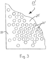
- FIG. 3 is a fragmentary top view of a non-electrically-conductive support that may be used as an alternative to the non-electrically-conductive support of FIGS. 2( a ) and 2 ( b );
- FIGS. 4( a ) and 4 ( b ) are schematic depictions of processes for preparing the non-electrically-conductive support of FIG. 1 by plasma dry etching;
- FIG. 5 is a schematic section view of a second embodiment of a solid polymer electrolyte composite membrane constructed according to the teachings of the present invention.
- FIG. 1 there is shown a schematic section view of a first embodiment of a solid polymer electrolyte composite membrane constructed according to the teachings of the present invention, said solid polymer electrolyte composite membrane being represented generally by reference numeral 11 .
- Composite membrane 11 comprises a non-electrically-conductive support 13 and a solid polymer electrolyte 15 , support 13 being impregnated with solid polymer electrolyte 15 .
- support 13 can be seen to be a generally sheet-like, unitary structure, preferably of high mechanical strength, having a top surface 17 and a bottom surface 19 .
- the thickness of support 13 may vary, depending upon the type of use to which membrane 11 is put and the types of pressures typically encountered by support 13 in such a use.
- support 13 preferably has a thickness suitable for withstanding pressures of 2000-5000 psi.
- support 13 has a thickness of about 5 ⁇ m to 50 ⁇ m, preferably about 7.5 ⁇ m to 15 ⁇ m.
- support 13 is preferably a rigid member; in addition, support 13 is preferably chemically resistant to acid and water hydrolysis at elevated temperatures.
- materials that may be used to make support 13 include, but are not limited to, perfluorinated polymers, polyvinylidene fluoride, poly(tetrafluoroethylene), polybenzimidazole, polyphenylenesulfide, polysulfone, polyethersulfone, polyesters, polyparaphenylene, polyquinoxaline, polyarylketone, polybenzazole, polyaramid, poly(etherether-ketone), liquid crystal polymers, polyimide and polyetherimide.
- perfluorinated polymers polyvinylidene fluoride, poly(tetrafluoroethylene), polybenzimidazole, polyphenylenesulfide, polysulfone, polyethersulfone, polyesters, polyparaphenylene, polyquinoxaline, polyarylketone, polybenzazole, polyaramid, poly(etherether-ketone
- PBI, PPS, PS, PEEK and PI are substantially stronger than PFSA and PTFE and, therefore, are preferred as materials for use in making support 13 .
- Kapton® polyimide (DuPont, Wilmington, Del.), which has a high strength, good hydrolysis stability and excellent thermal properties, is a particularly desirable material for use in making support 13 .
- Ultra-thin membranes of Kapton® polyimide (8.5 ⁇ m and 17 ⁇ m) are commercially available and may be used to make support 13 .
- VECTRA® liquid crystal polymers (Goodfellow, Cambridgeshire, UK) also have superb mechanical, chemical and thermal stability and may be used to make support 13 .
- ionomers may alternatively be used.
- suitable cationic ionomers include carboxylated, sulfonated or phosphorylated derivatives of the polymers discussed above.
- suitable anionic ionomers include amino, imimo, ammonium, sulfonium and phosphonium derivatives of the polymers discussed above.
- a plurality of pores 21 extend in a direct, i.e. straight-line, fashion from top surface 17 to bottom surface 19 of support 13 . It should be stressed that the base shape of the pore can be chosen from any two-dimensional geometric shape distributed in either regular or irregular fashion. As will be discussed further below, pores 21 are made by plasma etching and preferably each have a diameter of about 0.1 ⁇ m to 200 ⁇ m, preferably about 0.5 ⁇ m to 10 ⁇ m, with pores 21 constituting about 5% to 95%, more preferably about 40% to 70%, of support 13 .
- the conductance of a membrane including such a porous support can be easily estimated as:
- G Ts ⁇ * A * X + ( T - Ts ) ⁇ * A
- G the ionic conductance of the composite membrane
- ⁇ the ionic conductivity of the solid polymer electrolyte
- A the geometric area of the composite membrane
- X the percentage of pores in the support
- T the thickness of the composite membrane
- T s the thickness of the support.
- the conductance of the composite membrane is inversely proportional to the percentage of pores in the support.
- a support with 50% pores results in a composite membrane with conductance equivalent to a homogenous membrane twice as thick.
- a support with 50% pores may be fabricated.
- pores 21 are arranged in a uniform hexangular pattern over the entirety of support 13 , such pores 21 having, for example, a diameter of about 5 ⁇ m and a center-to-center spacing of about 7 ⁇ m. It is to be understood, however, that the present invention is not limited to the above-described pattern of pores and may encompass a variety of different patterns of pores. For example, as can be seen in FIG.
- FIG. 3 there is shown a fragmentary top view of a support 13 ′ having a plurality of pores 21 ′ that are arranged so that a lesser concentration of pores 21 ′ may be found in areas of higher membrane stress (e.g., at the membrane edge 23 or in local “hot spots” 25 ) and a greater concentration of pores 21 ′ may be found elsewhere.
- Pores 21 (and 21 ′) are made by plasma etching.
- FIG. 4( a ) there is schematically shown a first plasma etching process for forming pores 21 in support 13 (said process also being usable to form pores 21 ′ in support 13 ′), said process being represented generally by reference numeral 31 .
- process 31 begins in step 32 with the provision of a silicon wafer. (Other flat substrates including flat metal sheets may be used instead of a silicon wafer.)
- a first thin layer of aluminum is sputtered onto the silicon wafer.
- a layer of what will become support layer 13 preferably polyimide, is spin coated onto the aluminum layer.
- a second thin layer of aluminum is sputtered onto the support layer precursor.
- a layer of photoresist material is spin coated onto the second aluminum layer.
- the photoresist layer is imaged and then developed, thereby creating pores in the photoresist layer that expose the underlying second aluminum layer.
- the exposed areas of the second aluminum layer are etched with acid, thereby creating pores in the second aluminum layer that expose the underlying support layer.
- the photoresist layer is removed.
- the exposed areas of the support layer are plasma etched.
- the aluminum layers are removed from the etched support.
- step 33 may be omitted entirely, with the support layer being deposited directly onto the silicon wafer (or other flat substrate used).
- spin coating is described above as being used to form the support and photoresist layers, direct coating processes may also be used to increase speed and lower cost. Examples of suitable coating techniques include gravure coating, immersion (dip) coating, metering rod (Meyer bar) coating, slot die coating, rotary screen and air knife coating.
- pores in the support are formed by plasma etching, with an aspect ratio in the neighborhood of 8 to 10.
- pores formed by plasma etching have tendency to diverge as they pass through a substrate (as opposed to being collimated). Consequently, such pores should not be spaced so closely to one another that they intersect.
- process 31 is described herein as a batch process, the actual manufacturing process can readily be adapted to a continuous, fully-automated production line.
- FIG. 4( b ) there is schematically shown an example of a continuous manufacturing process, said process being represented generally by reference numeral 43 .
- Process 43 begins with the support precursor being provided in roll form, as represented by step 44 .
- a thin layer of aluminum is sputtered onto the support roll.
- a layer of photoresist is coated onto the aluminum layer.
- steps 47 - 1 and 47 - 2 the photoresist is image and developed, respectively, to expose portions of the underlying aluminum layer.
- the aluminum layer is acid etched to expose portions of the underlying support layer.
- the support layer is plasma etched.
- the aluminum layer is removed from the etched support.
- solid polymer electrolyte 15 can be seen to fill pores 21 and to cover thinly top surface 17 and bottom surface 19 of support 13 .
- suitable materials for use as solid polymer electrolyte 15 include (i) polymer compositions that contain metal salts; (ii) polymeric gels that contain electrolytes; and (iii) ion exchange resins.
- a carboxylated, sulfonated or phosphorylated polymer is preferably used as solid polymer electrolyte 15 .
- a polymer containing amino, imimo, ammonium, sulfonium, and phosphonium groups is preferably used as solid polymer electrolyte 15 .
- inorganic ionically-conductive materials such as metal oxide (e.g., TiO 2 ), silicon oxide, metal phosphates (e.g., zirconium phosphate) or heteropolyacids, may be impregnated into the solid polymer electrolyte 15 .
- a preferred material for use as solid polymer electrolyte 15 is a perfluorosulfonic acid (PFSA) membrane, such as is commercially available from DuPont (Wilmington, Del.) as NAFION® PFSA polymer.
- PFSA perfluorosulfonic acid
- NAFION® PFSA polymer particularly preferred are those having an equivalent weight of 200 to 2000, even more preferably those having an equivalent weight of 500 to 1200, the optimal equivalent weight depending on the use to which membrane 11 is applied.
- Solid polymer electrolyte 15 may be coupled to support 13 .
- One such technique involves providing the solid polymer electrolyte in the form of a solution/dispersion (e.g., Nafion® 1100 in water or isopropanol) and then coating support 13 with said solution/dispersion.
- suitable coating techniques include gravure coating, immersion (dip) coating, metering rod (Meyer bar) coating, slot die coating, rotary screen and air knife coating.
- the optimal coating technique for any particular case will depend on factors, such as instrument complexity, thickness accuracy, operation efficiency, initial investment, and the like.
- one or more additional coatings may thereafter be applied. Said one or more additional coatings either may be of the same solution/dispersion previously applied in order to build up the thickness of the solid polymer electrolyte or may be different from the initial solution/dispersion in order to obtain a composite membrane with a multilayer electrolyte structure having desired properties. (An example of a composite membrane possessing such a multilayer structure is shown in FIG.
- said composite membrane 51 comprising a support 13 , a first solid polymer electrolyte 53 and a second polymer electrolyte 55 .
- the layer or layers are preferably cured by heating at a temperature greater than the glass transition temperature of the ionomer (e.g., 100° C. to 400° C., preferably 160° C. for 15 minutes). Such curing, which serves to sinter or anneal the ionomer, further enhances the mechanical properties of the membrane.
- mask coating technology may be used to create a composite membrane wherein the solid polymer electrolyte is confined to certain patches or regions.
- the solid polymer electrolyte may be applied by spraying the polymer electrolyte solution/dispersion onto support 13 .
- Conventional spraying techniques may be used for this purpose. Such spraying is preferably performed at 80° C. and does not require a subsequent solvent evaporation step.
- Micro-spraying may be used to create solid polymer electrolyte patches on the support, such patches, if desired, being far smaller than those capable of being produced by masked coating techniques.
- Still another technique for incorporating the solid polymer electrolyte 15 into support 13 involves a membrane extrusion technique.
- a membrane extrusion technique comprises providing the solid polymer electrolyte in the form of a thin membrane, stacking the thin ionomer membrane on the top and/or bottom surfaces of support 13 , and then pressing the stack together at an elevated pressure, preferably above the melting point or glass transition temperature of the ionomer.
- the total thickness of membrane 11 is preferably about 5 to 300 ⁇ m, more preferably 10 to 75 ⁇ m, with the thickness of the membrane being governed by application requirements.
- a water electrolyzer requires a thicker membrane due to its high differential pressure while an ultra-thin membrane is suitable for super capacitors since no dynamic pressure is involved for their operation.
- Membrane and electrode assemblies comprising the composite membrane of the present invention can be fabricated by pressing a precast Pt-supported on carbon/ionomer ink onto each side of the composite membrane.
- the foregoing method is typically referred to as the decal transfer method.
- catalyst ink can be directly coated or sprayed onto the top and bottom surfaces of the membrane. This direct coating of the catalyst ink is not practical for conventional ionomer membranes since such membranes change dimension when contacted with the ink. Since the composite membrane of the present invention has excellent dimensional stability when contacted with swelling agents, such as water or alcohols, the catalyst ink can be directly applied to the membrane.
- the diffusion medium of this technique is a porous electrically-conductive material, which is typically in the form of a thin sheet.
- a microporous layer prepared from carbon black and a polymer binder may be applied to the diffusion medium.
- the catalyst is then sprayed onto the diffusion medium to form a diffusion electrode.
- a catalyst-loaded diffusion electrode is then pressed onto each side of the composite membrane to form a full MEA.
- Such an MEA may be used, for example, by being sandwiched between two pieces of teflonated porous carbon paper and assembled into a functional PEM fuel cell as described in U.S. Pat. No. 4,215,183, inventor MacLoed, which issued Jul. 29, 1980, the disclosure of which is incorporated herein by reference, or by being sandwiched between porous titanium metal meshes or sinters and assembled into an electrolysis cell as described in U.S. Pat. No. 6,500,319, inventors LaConti et al., which issued Dec. 31, 2002, the disclosure of which is incorporated herein by reference.
Abstract
Description
| TABLE I | |
| Material, condition | Young's Modulus (Mpa) |
| Nafion ® 112 PFSA membrane, dry 20° C. | 300 |
| Nafion ® 112 PFSA membrane, wet 80° C. | 70 |
| Poly(tetrafluoroethylene) (PTFE) | 400 |
| Polybenzimidazole (PBI) | 5900 |
| Polyphenylenesulfide (PPS) | 3300 |
| Polysulfone (PS) | 2600 |
| Poly(etherether-ketone) (PEEK) | 2700 |
| Polyimide (PI) | 2900 |
where G is the ionic conductance of the composite membrane, σ is the ionic conductivity of the solid polymer electrolyte, A is the geometric area of the composite membrane, X is the percentage of pores in the support, T is the thickness of the composite membrane and Ts is the thickness of the support.
Claims (38)
Priority Applications (3)
| Application Number | Priority Date | Filing Date | Title |
|---|---|---|---|
| US10/970,685 US7807063B2 (en) | 2004-09-28 | 2004-10-21 | Solid polymer electrolyte composite membrane comprising plasma etched porous support |
| PCT/US2005/034571 WO2006036957A2 (en) | 2004-09-28 | 2005-09-28 | Solid polymer electrolyte composite membrane comprising plasma etched porous support |
| US12/924,751 US8962132B2 (en) | 2004-09-28 | 2010-10-04 | Solid polymer electrolyte composite membrane comprising a porous support and a solid polymer electrolyte including a dispersed reduced noble metal or noble metal oxide |
Applications Claiming Priority (2)
| Application Number | Priority Date | Filing Date | Title |
|---|---|---|---|
| US61376904P | 2004-09-28 | 2004-09-28 | |
| US10/970,685 US7807063B2 (en) | 2004-09-28 | 2004-10-21 | Solid polymer electrolyte composite membrane comprising plasma etched porous support |
Related Child Applications (1)
| Application Number | Title | Priority Date | Filing Date |
|---|---|---|---|
| US12/924,751 Continuation-In-Part US8962132B2 (en) | 2004-09-28 | 2010-10-04 | Solid polymer electrolyte composite membrane comprising a porous support and a solid polymer electrolyte including a dispersed reduced noble metal or noble metal oxide |
Publications (2)
| Publication Number | Publication Date |
|---|---|
| US20060065522A1 US20060065522A1 (en) | 2006-03-30 |
| US7807063B2 true US7807063B2 (en) | 2010-10-05 |
Family
ID=36097768
Family Applications (1)
| Application Number | Title | Priority Date | Filing Date |
|---|---|---|---|
| US10/970,685 Active 2028-12-31 US7807063B2 (en) | 2004-09-28 | 2004-10-21 | Solid polymer electrolyte composite membrane comprising plasma etched porous support |
Country Status (2)
| Country | Link |
|---|---|
| US (1) | US7807063B2 (en) |
| WO (1) | WO2006036957A2 (en) |
Cited By (12)
| Publication number | Priority date | Publication date | Assignee | Title |
|---|---|---|---|---|
| US9728802B2 (en) | 2013-05-14 | 2017-08-08 | Giner, Inc. | Micromold methods for fabricating perforated substrates and for preparing solid polymer electrolyte composite membranes |
| US10333157B2 (en) | 2014-11-25 | 2019-06-25 | Johnson Matthey Fuel Cells Limited | Membrane-seal assembly |
| GB201914335D0 (en) | 2019-10-04 | 2019-11-20 | Johnson Matthey Fuel Cells Ltd | Membrane electrode assembly |
| GB202001890D0 (en) | 2020-02-12 | 2020-03-25 | Johnson Matthey Fuel Cells Ltd | Catalyst |
| GB202003650D0 (en) | 2020-03-13 | 2020-04-29 | Johnson Matthey Fuel Cells Ltd | Catalyst support |
| WO2020148545A1 (en) | 2019-01-17 | 2020-07-23 | Johnson Matthey Fuel Cells Limited | Membrane |
| WO2021032994A1 (en) | 2019-08-22 | 2021-02-25 | Johnson Matthey Fuel Cells Limited | Catalysed membrane |
| US11024876B2 (en) | 2016-11-01 | 2021-06-01 | Giner, Inc. | Composite membrane comprising solid electrolyte, method of making said composite membrane, and electrochemical cell comprising said composite membrane |
| WO2021116691A1 (en) | 2019-12-12 | 2021-06-17 | Johnson Matthey Fuel Cells Limited | Electrocatalyst ink |
| GB202108369D0 (en) | 2021-06-11 | 2021-07-28 | Johnson Matthey Fuel Cells Ltd | Electrocatalyst ink |
| WO2021214466A1 (en) | 2020-04-23 | 2021-10-28 | Johnson Matthey Fuel Cells Limited | Electrocatalyst layer decal |
| WO2022008894A1 (en) | 2020-07-07 | 2022-01-13 | Johnson Matthey Fuel Cells Limited | Catalyst preparation |
Families Citing this family (11)
| Publication number | Priority date | Publication date | Assignee | Title |
|---|---|---|---|---|
| US7867669B2 (en) * | 2004-09-28 | 2011-01-11 | Giner Electrochemical Systems, Llc | Solid polymer electrolyte composite membrane comprising laser micromachined porous support |
| US8962132B2 (en) | 2004-09-28 | 2015-02-24 | Giner, Inc. | Solid polymer electrolyte composite membrane comprising a porous support and a solid polymer electrolyte including a dispersed reduced noble metal or noble metal oxide |
| US7947405B2 (en) * | 2004-09-29 | 2011-05-24 | Giner Electrochemical Systems, Llc | Solid polymer electrolyte composite membrane comprising porous ceramic support |
| GB201003230D0 (en) * | 2010-02-26 | 2010-04-14 | Johnson Matthey Plc | Membrane |
| GB201118288D0 (en) | 2011-10-24 | 2011-12-07 | Johnson Matthey Plc | Ion-conducting membrane |
| KR101890747B1 (en) | 2011-11-03 | 2018-10-01 | 삼성전자주식회사 | Ion conductor filling composition, method of preparing ion exchange membrane, ion exchange membrane and redox flow battery |
| US8648315B1 (en) * | 2012-08-14 | 2014-02-11 | Transmute, Inc. | Accelerator having a multi-channel micro-collimator |
| KR20160120078A (en) * | 2015-04-07 | 2016-10-17 | 삼성에스디아이 주식회사 | Polymer electrolyte membrane for fuel cell and membrane-electrode assembly for fuel cell including the same |
| CN108976938B (en) * | 2018-07-10 | 2020-11-17 | 福建师范大学 | Method for preparing coating film containing monovalent ion phosphate coating layer |
| EP4326925A2 (en) * | 2022-02-04 | 2024-02-28 | Johnson Matthey Hydrogen Technologies Limited | Catalyst coated membranes for water electrolysers |
| EP4296406A1 (en) * | 2022-06-22 | 2023-12-27 | Vito NV | Hybrid ceramic polymer membrane for water electrolysis application |
Citations (19)
| Publication number | Priority date | Publication date | Assignee | Title |
|---|---|---|---|---|
| US3282875A (en) | 1964-07-22 | 1966-11-01 | Du Pont | Fluorocarbon vinyl ether polymers |
| US3972727A (en) * | 1975-08-13 | 1976-08-03 | The United States Of America As Represented By The Administrator Of The National Aeronautics And Space Administration | Rechargeable battery which combats shape change of the zinc anode |
| US4470889A (en) | 1980-06-11 | 1984-09-11 | The Dow Chemical Company | Electrolytic cell having an improved ion exchange membrane and process for operating |
| US4478695A (en) | 1980-06-11 | 1984-10-23 | The Dow Chemical Company | Sulfonic acid electrolytic cell membranes and use thereof in the electrolysis of sodium chloride |
| US5569855A (en) | 1992-11-16 | 1996-10-29 | Forschungszentrum Karlsruhe Gmbh | Method of manufacturing a frame-mounted membrane |
| US6350389B1 (en) | 1998-06-12 | 2002-02-26 | The University Of Tokyo | Method for producing porous diamond |
| US20020182482A1 (en) | 2001-06-01 | 2002-12-05 | Hockaday Robert G. | Catalytic hydrogen vent filter for batteries |
| US6492431B1 (en) | 1998-02-20 | 2002-12-10 | Lynntech, Inc. | Process of making a composite membrane |
| US20030138656A1 (en) * | 2002-01-07 | 2003-07-24 | Sparks Douglas Ray | Method of forming a reactive material and article formed thereby |
| US6635384B2 (en) | 1998-03-06 | 2003-10-21 | Gore Enterprise Holdings, Inc. | Solid electrolyte composite for electrochemical reaction apparatus |
| WO2004045750A1 (en) | 2002-11-19 | 2004-06-03 | Universite Catholique De Louvain | Method for producing pores in a thin polyimide sheet |
| US20040126638A1 (en) | 2002-12-31 | 2004-07-01 | Jong-Pyng Chen | Layered proton exchange membrane and method for preparing the same |
| US6793711B1 (en) * | 1999-12-07 | 2004-09-21 | Eltron Research, Inc. | Mixed conducting membrane for carbon dioxide separation and partial oxidation reactions |
| US20050026030A1 (en) | 2003-07-28 | 2005-02-03 | Peter Mardilovich | Fuel cell support structure and method of manufacture |
| US20050074651A1 (en) * | 2001-01-26 | 2005-04-07 | Masayuki Kidai | Polymer electrolyte film and method for preparation of the same, and solid polymer type fuel cell using the same |
| US20050095486A1 (en) | 2002-02-15 | 2005-05-05 | Shiro Hamamoto | Cluster ion exchange membrane and electrolyte membrane electrode connection body |
| US20050263452A1 (en) * | 1999-12-08 | 2005-12-01 | Jacobson James D | Microporous filter membrane, method of making microporous filter membrane and separator employing microporous filter membranes |
| US20060065521A1 (en) | 2004-09-28 | 2006-03-30 | Han Liu | Solid polymer electrolyte composite membrane comprising laser micromachined porous support |
| US20060183011A1 (en) | 2004-09-29 | 2006-08-17 | Mittelsteadt Cortney K | Solid polymer electrolyte composite membrane comprising porous ceramic support |
-
2004
- 2004-10-21 US US10/970,685 patent/US7807063B2/en active Active
-
2005
- 2005-09-28 WO PCT/US2005/034571 patent/WO2006036957A2/en active Application Filing
Patent Citations (19)
| Publication number | Priority date | Publication date | Assignee | Title |
|---|---|---|---|---|
| US3282875A (en) | 1964-07-22 | 1966-11-01 | Du Pont | Fluorocarbon vinyl ether polymers |
| US3972727A (en) * | 1975-08-13 | 1976-08-03 | The United States Of America As Represented By The Administrator Of The National Aeronautics And Space Administration | Rechargeable battery which combats shape change of the zinc anode |
| US4470889A (en) | 1980-06-11 | 1984-09-11 | The Dow Chemical Company | Electrolytic cell having an improved ion exchange membrane and process for operating |
| US4478695A (en) | 1980-06-11 | 1984-10-23 | The Dow Chemical Company | Sulfonic acid electrolytic cell membranes and use thereof in the electrolysis of sodium chloride |
| US5569855A (en) | 1992-11-16 | 1996-10-29 | Forschungszentrum Karlsruhe Gmbh | Method of manufacturing a frame-mounted membrane |
| US6492431B1 (en) | 1998-02-20 | 2002-12-10 | Lynntech, Inc. | Process of making a composite membrane |
| US6635384B2 (en) | 1998-03-06 | 2003-10-21 | Gore Enterprise Holdings, Inc. | Solid electrolyte composite for electrochemical reaction apparatus |
| US6350389B1 (en) | 1998-06-12 | 2002-02-26 | The University Of Tokyo | Method for producing porous diamond |
| US6793711B1 (en) * | 1999-12-07 | 2004-09-21 | Eltron Research, Inc. | Mixed conducting membrane for carbon dioxide separation and partial oxidation reactions |
| US20050263452A1 (en) * | 1999-12-08 | 2005-12-01 | Jacobson James D | Microporous filter membrane, method of making microporous filter membrane and separator employing microporous filter membranes |
| US20050074651A1 (en) * | 2001-01-26 | 2005-04-07 | Masayuki Kidai | Polymer electrolyte film and method for preparation of the same, and solid polymer type fuel cell using the same |
| US20020182482A1 (en) | 2001-06-01 | 2002-12-05 | Hockaday Robert G. | Catalytic hydrogen vent filter for batteries |
| US20030138656A1 (en) * | 2002-01-07 | 2003-07-24 | Sparks Douglas Ray | Method of forming a reactive material and article formed thereby |
| US20050095486A1 (en) | 2002-02-15 | 2005-05-05 | Shiro Hamamoto | Cluster ion exchange membrane and electrolyte membrane electrode connection body |
| WO2004045750A1 (en) | 2002-11-19 | 2004-06-03 | Universite Catholique De Louvain | Method for producing pores in a thin polyimide sheet |
| US20040126638A1 (en) | 2002-12-31 | 2004-07-01 | Jong-Pyng Chen | Layered proton exchange membrane and method for preparing the same |
| US20050026030A1 (en) | 2003-07-28 | 2005-02-03 | Peter Mardilovich | Fuel cell support structure and method of manufacture |
| US20060065521A1 (en) | 2004-09-28 | 2006-03-30 | Han Liu | Solid polymer electrolyte composite membrane comprising laser micromachined porous support |
| US20060183011A1 (en) | 2004-09-29 | 2006-08-17 | Mittelsteadt Cortney K | Solid polymer electrolyte composite membrane comprising porous ceramic support |
Cited By (18)
| Publication number | Priority date | Publication date | Assignee | Title |
|---|---|---|---|---|
| US9728802B2 (en) | 2013-05-14 | 2017-08-08 | Giner, Inc. | Micromold methods for fabricating perforated substrates and for preparing solid polymer electrolyte composite membranes |
| US10333157B2 (en) | 2014-11-25 | 2019-06-25 | Johnson Matthey Fuel Cells Limited | Membrane-seal assembly |
| US11024876B2 (en) | 2016-11-01 | 2021-06-01 | Giner, Inc. | Composite membrane comprising solid electrolyte, method of making said composite membrane, and electrochemical cell comprising said composite membrane |
| WO2020148545A1 (en) | 2019-01-17 | 2020-07-23 | Johnson Matthey Fuel Cells Limited | Membrane |
| WO2021032994A1 (en) | 2019-08-22 | 2021-02-25 | Johnson Matthey Fuel Cells Limited | Catalysed membrane |
| US11705568B2 (en) | 2019-08-22 | 2023-07-18 | Johnson Matthey Hydrogen Technologies Limited | Catalysed membrane |
| GB201914335D0 (en) | 2019-10-04 | 2019-11-20 | Johnson Matthey Fuel Cells Ltd | Membrane electrode assembly |
| WO2021064410A1 (en) | 2019-10-04 | 2021-04-08 | Johnson Matthey Fuel Cells Limited | Membrane electrode assembly |
| WO2021116691A1 (en) | 2019-12-12 | 2021-06-17 | Johnson Matthey Fuel Cells Limited | Electrocatalyst ink |
| WO2021161022A1 (en) | 2020-02-12 | 2021-08-19 | Johnson Matthey Fuel Cells Limited | Catalyst |
| GB202001890D0 (en) | 2020-02-12 | 2020-03-25 | Johnson Matthey Fuel Cells Ltd | Catalyst |
| GB202003650D0 (en) | 2020-03-13 | 2020-04-29 | Johnson Matthey Fuel Cells Ltd | Catalyst support |
| WO2021181113A1 (en) | 2020-03-13 | 2021-09-16 | Johnson Matthey Fuel Cells Limited | Catalyst support |
| WO2021214466A1 (en) | 2020-04-23 | 2021-10-28 | Johnson Matthey Fuel Cells Limited | Electrocatalyst layer decal |
| WO2022008894A1 (en) | 2020-07-07 | 2022-01-13 | Johnson Matthey Fuel Cells Limited | Catalyst preparation |
| WO2022258965A1 (en) | 2021-06-11 | 2022-12-15 | Johnson Matthey Hydrogen Technologies Limited | Electrocatalyst ink |
| GB2607883A (en) | 2021-06-11 | 2022-12-21 | Johnson Matthey Hydrogen Tech Limited | Electrocatalyst ink |
| GB202108369D0 (en) | 2021-06-11 | 2021-07-28 | Johnson Matthey Fuel Cells Ltd | Electrocatalyst ink |
Also Published As
| Publication number | Publication date |
|---|---|
| US20060065522A1 (en) | 2006-03-30 |
| WO2006036957A2 (en) | 2006-04-06 |
| WO2006036957A3 (en) | 2007-12-13 |
Similar Documents
| Publication | Publication Date | Title |
|---|---|---|
| US7807063B2 (en) | Solid polymer electrolyte composite membrane comprising plasma etched porous support | |
| US7867669B2 (en) | Solid polymer electrolyte composite membrane comprising laser micromachined porous support | |
| US7947405B2 (en) | Solid polymer electrolyte composite membrane comprising porous ceramic support | |
| US8962132B2 (en) | Solid polymer electrolyte composite membrane comprising a porous support and a solid polymer electrolyte including a dispersed reduced noble metal or noble metal oxide | |
| EP1658652B1 (en) | Process for the preparation of a unitized membrane electrode assembly | |
| US7901829B2 (en) | Enhanced catalyst interface for membrane electrode assembly | |
| KR101754122B1 (en) | Reinforced water electrolysis membrane and membrane electrode assembly using the same | |
| US20170288234A1 (en) | Catalyst layer assembly | |
| CA2488908C (en) | Method of making membrane electrode assemblies | |
| EP1615282A1 (en) | Solid polymer electrolyte membrane, membrane electrode assembly for solid polymer fuel cell, and method for producing solid polymer electrolyte membrane | |
| CA2436009A1 (en) | Polymer electrolyte membrane, a method of rproducing thereof and a polymer electrolyte type fuel cell using the same | |
| US7090738B2 (en) | Method of manufacturing membrane electrode assembly | |
| Slade et al. | The Ionic Conductivity of a Nafion® 1100 Series of Proton‐exchange Membranes Re‐cast from Butan‐1‐ol and Propan‐2‐ol | |
| US20030219645A1 (en) | Treated gas diffusion backings and their use in fuel cells | |
| JP4824946B2 (en) | Electrolyte membrane with protective film and production method thereof. | |
| US8518597B2 (en) | Catalytic layer-electrolytic membrane assembly, transfer sheet, and production process thereof | |
| JP6675320B2 (en) | Membrane seal assembly | |
| KR101312971B1 (en) | Hydrocarbon based polyelectrolyte separation membrane surface-treated with fluorinated ionomer, membrane electrode assembly, and fuel cell | |
| WO2005011041A1 (en) | Process for making planar framed membrane electrode assembly arrays, and fuel cells containing the same | |
| CN106256039B (en) | The method for manufacturing the film seal assembly of enhancing | |
| US9761897B2 (en) | Fuel cell durability by orthogonally oriented anisotropic external reinforce layers | |
| US8940461B2 (en) | Method for membrane electrode assembly fabrication and membrane electrode assembly | |
| US20230057062A1 (en) | Membrane-electrode assembly and method for manufacturing same | |
| WO2023105229A2 (en) | Method | |
| JP2003323898A (en) | Processed gas diffusion backing and its use for fuel battery |
Legal Events
| Date | Code | Title | Description |
|---|---|---|---|
| AS | Assignment |
Owner name: GINER ELECTROCHEMICAL SYSTEMS, LLC, MASSACHUSETTS Free format text: ASSIGNMENT OF ASSIGNORS INTEREST;ASSIGNORS:LIU, HAN;LACONTI, ANTHONY B.;REEL/FRAME:016233/0525 Effective date: 20050114 |
|
| STCF | Information on status: patent grant |
Free format text: PATENTED CASE |
|
| AS | Assignment |
Owner name: GINER, INC., MASSACHUSETTS Free format text: MERGER;ASSIGNOR:GINER ELECTROCHEMICAL SYSTEMS, L.L.C.;REEL/FRAME:027305/0332 Effective date: 20111104 |
|
| FPAY | Fee payment |
Year of fee payment: 4 |
|
| MAFP | Maintenance fee payment |
Free format text: PAYMENT OF MAINTENANCE FEE, 8TH YR, SMALL ENTITY (ORIGINAL EVENT CODE: M2552) Year of fee payment: 8 |
|
| AS | Assignment |
Owner name: GINER ELX, INC., MASSACHUSETTS Free format text: ASSIGNMENT OF ASSIGNORS INTEREST;ASSIGNOR:GINER, INC.;REEL/FRAME:053459/0963 Effective date: 20200622 |
|
| AS | Assignment |
Owner name: GENERATE PPL SPV I, LLC, CALIFORNIA Free format text: SECURITY INTEREST;ASSIGNOR:GINER ELX SUB, LLC;REEL/FRAME:053719/0284 Effective date: 20200904 |
|
| AS | Assignment |
Owner name: PLUG POWER INC., NEW YORK Free format text: ASSIGNMENT OF ASSIGNORS INTEREST;ASSIGNOR:GINER ELX, SUB, LLC;REEL/FRAME:054024/0297 Effective date: 20201009 |
|
| AS | Assignment |
Owner name: GINER ELX SUB, LLC, NEW YORK Free format text: MERGER;ASSIGNOR:GINER ELX, INC.;REEL/FRAME:054034/0309 Effective date: 20200622 |
|
| AS | Assignment |
Owner name: GINER ELX SUB, INC., NEW YORK Free format text: MERGER;ASSIGNOR:GINER ELX, INC.;REEL/FRAME:054111/0464 Effective date: 20200622 |
|
| FEPP | Fee payment procedure |
Free format text: ENTITY STATUS SET TO UNDISCOUNTED (ORIGINAL EVENT CODE: BIG.); ENTITY STATUS OF PATENT OWNER: LARGE ENTITY |
|
| MAFP | Maintenance fee payment |
Free format text: PAYMENT OF MAINTENANCE FEE, 12TH YEAR, LARGE ENTITY (ORIGINAL EVENT CODE: M1553); ENTITY STATUS OF PATENT OWNER: LARGE ENTITY Year of fee payment: 12 |