US7806903B2 - Clipping instrument for an endoscopic surgical device - Google Patents
Clipping instrument for an endoscopic surgical device Download PDFInfo
- Publication number
- US7806903B2 US7806903B2 US12/131,316 US13131608A US7806903B2 US 7806903 B2 US7806903 B2 US 7806903B2 US 13131608 A US13131608 A US 13131608A US 7806903 B2 US7806903 B2 US 7806903B2
- Authority
- US
- United States
- Prior art keywords
- flexible sheath
- sleeve
- clipping
- arms
- clip assembly
- Prior art date
- Legal status (The legal status is an assumption and is not a legal conclusion. Google has not performed a legal analysis and makes no representation as to the accuracy of the status listed.)
- Expired - Fee Related, expires
Links
- 210000000078 claw Anatomy 0.000 description 12
- 230000000712 assembly Effects 0.000 description 9
- 238000000429 assembly Methods 0.000 description 9
- 238000002674 endoscopic surgery Methods 0.000 description 1
- 238000001727 in vivo Methods 0.000 description 1
- 239000002184 metal Substances 0.000 description 1
- 238000000034 method Methods 0.000 description 1
- 229940058401 polytetrafluoroethylene Drugs 0.000 description 1
- 239000004810 polytetrafluoroethylene Substances 0.000 description 1
- 229910001220 stainless steel Inorganic materials 0.000 description 1
- 239000010935 stainless steel Substances 0.000 description 1
Images


Classifications
-
- A—HUMAN NECESSITIES
- A61—MEDICAL OR VETERINARY SCIENCE; HYGIENE
- A61B—DIAGNOSIS; SURGERY; IDENTIFICATION
- A61B17/00—Surgical instruments, devices or methods, e.g. tourniquets
- A61B17/08—Wound clamps or clips, i.e. not or only partly penetrating the tissue ; Devices for bringing together the edges of a wound
- A61B17/083—Clips, e.g. resilient
-
- A—HUMAN NECESSITIES
- A61—MEDICAL OR VETERINARY SCIENCE; HYGIENE
- A61B—DIAGNOSIS; SURGERY; IDENTIFICATION
- A61B17/00—Surgical instruments, devices or methods, e.g. tourniquets
- A61B17/10—Surgical instruments, devices or methods, e.g. tourniquets for applying or removing wound clamps, e.g. containing only one clamp or staple; Wound clamp magazines
-
- A—HUMAN NECESSITIES
- A61—MEDICAL OR VETERINARY SCIENCE; HYGIENE
- A61B—DIAGNOSIS; SURGERY; IDENTIFICATION
- A61B17/00—Surgical instruments, devices or methods, e.g. tourniquets
- A61B17/12—Surgical instruments, devices or methods, e.g. tourniquets for ligaturing or otherwise compressing tubular parts of the body, e.g. blood vessels, umbilical cord
- A61B17/122—Clamps or clips, e.g. for the umbilical cord
- A61B17/1227—Spring clips
-
- A—HUMAN NECESSITIES
- A61—MEDICAL OR VETERINARY SCIENCE; HYGIENE
- A61B—DIAGNOSIS; SURGERY; IDENTIFICATION
- A61B17/00—Surgical instruments, devices or methods, e.g. tourniquets
- A61B17/12—Surgical instruments, devices or methods, e.g. tourniquets for ligaturing or otherwise compressing tubular parts of the body, e.g. blood vessels, umbilical cord
- A61B17/128—Surgical instruments, devices or methods, e.g. tourniquets for ligaturing or otherwise compressing tubular parts of the body, e.g. blood vessels, umbilical cord for applying or removing clamps or clips
- A61B17/1285—Surgical instruments, devices or methods, e.g. tourniquets for ligaturing or otherwise compressing tubular parts of the body, e.g. blood vessels, umbilical cord for applying or removing clamps or clips for minimally invasive surgery
Definitions
- the present invention relates to a surgical device having a clipping instrument to be inserted through a forceps channel of an endoscope.
- a clip having a pair of openable/closable arms and a fastening ring loosely fit around proximal portions of the arms is arranged in a distal end portion of a flexible sheath.
- the clip is configured such that the arms open and close as an operation wire, arranged in parallel with an axial direction of the flexible sheath, is advanced toward the distal end to push the fastening ring and retracted toward a proximal end to pull the fastening ring.
- the clip can be detached from the operation wire with its arms closed according to the operations to the operation wire.
- the clipping instrument is provided a sleeve having a plurality (for example, three or four) of slits, which are parallel to an axial direction, at the distal end of the flexible sheath so that the fastening ring can resiliently outstretch the sleeve and penetrate therethrough, and the arms can be maintained open.
- the proximal portion of the clip remains inside the sleeve, and an outline of the remaining proximal portion is generally smaller than an outer diameter of the fastening ring. Therefore, the proximal portion may not be firmly held by the sleeve as the sleeve resiliently deforms, and the arms projecting out of the sleeve may be unstable and undesirably swayed. Thus, the clip may not be accurately handled to be pressed to a targeted portion of the body tissue.
- the present invention is advantageous in that an endoscopic surgical device with a clipping instrument, in which the clipping arms can be steadily held open and operated in a stable posture, is provided.
- a clipping instrument for an endoscope.
- the clipping instrument includes a flexible sheath to be inserted into an instrument channel of the endoscope, an operation wire, which is configured to be forwarded and retracted in an axial direction of the flexible sheath, at least one detachable clip assembly, including a pair of openable and closable clipping arms and a fastening ring to encircle proximal portions of the clipping arms, arranged in vicinity of a distal end portion of the flexible sheath with the clipping arms closed.
- the clipping arms are configured to be projected forward to open outside the flexible sheath and to be closed to clip onto a treatment object outside the flexible sheath according to forwarding and retracting movements of the fastening ring through the operation wire.
- the clipping instrument further includes a sleeve formed to have a plurality of slits and arranged at the distal end portion of the flexible sheath, and a blade spring piece to be attached to the sleeve.
- the blade spring piece has a plurality of blade springs, each of which is settled in one of the plurality of the slits of the sleeve when the blade spring piece is attached to the sleeve.
- the plurality of blade springs can resiliently hold the detachable clip assembly, being projected out of the flexible sheath, in a posture with respect to the flexible sheath.
- FIG. 1 is an overall cross-sectional side view of a clipping instrument with arms of a clip assembly being closed in a flexible sheath according to an embodiment of the present invention.
- FIG. 2 is a partial and cross-sectional side view of the clip assembly being closed in the flexible sheath according to the embodiment of the present invention.
- FIG. 3 is a perspective view of the clip assembly according to the embodiment of the present invention.
- FIG. 4 is an exploded view of the clip assembly according to the embodiment of the present invention.
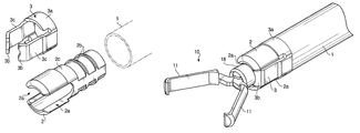
- FIG. 5 is a perspective view of a sleeve and a blade spring piece in a distal end portion of the flexible sheath according to the embodiment of the present invention.
- FIG. 6 is an exploded view of the sleeve and the blade spring piece in the distal end portion of the flexible sheath according to the embodiment of the present invention.
- FIG. 7 is a side view of the clipping instrument with the arms of the clip assembly protruded outward according to the embodiment of the present invention.
- FIG. 8 is an overall cross-sectional side view of the clipping instrument with the clip assembly projecting out of the flexible sheath according to the embodiment of the present invention.
- FIG. 9 is a cross-sectional side view of the clip assembly projecting out of the flexible sheath according to the embodiment of the present invention.
- FIG. 10 is a cross-sectional side view of the clip assembly projecting further out of the flexible sheath according to the embodiment of the present invention.
- FIG. 11 is an overall cross-sectional side view of the clipping instrument with the arms open according to the embodiment of the present invention.
- FIG. 12 is a perspective view of the clipping instrument with the arms of the clip assembly open according to the embodiment of the present invention.
- FIG. 13 is an overall cross-sectional side view of the clipping instrument with the arms closed according to the embodiment of the present invention.
- FIG. 14 is an overall cross-sectional side view of the clipping instrument with the clip assembly detached according to the embodiment of the present invention.
- FIG. 1 is an overall cross-sectional side view of a clipping instrument 100 with arms 11 of a clip assembly 10 being closed in a flexible sheath 1 according to an embodiment of the present invention.
- FIG. 2 is a partial and cross-sectional side view of the clip assembly 10 being closed in the flexible sheath 1 according to the embodiment of the present invention.
- the flexible sheath 1 is made of, for example, poly-tetra-fluoro-ethylene and is inserted into a forceps channel (not shown) of an endoscope (not shown).
- the flexible sheath 1 is provided with a sleeve 2 , which is made of a metal (e.g., stainless steel) at a distal end, and a blade spring piece 3 to prevent the clip assembly 10 from swaying is attached to the sleeve 2 .
- a sleeve 2 which is made of a metal (e.g., stainless steel) at a distal end, and a blade spring piece 3 to prevent the clip assembly 10 from swaying is attached to the sleeve 2 .
- an operating wire 4 to be advanced and retracted in parallel with the axial direction of the flexible sheath 1 is provided inside the flexible sheath 1 .
- the operating wire 4 is connected to an operating unit (not shown) at a proximal end thereof and can be advanced and retracted in accordance with an operation given to the operating unit.
- the operating wire 4 is fixedly connected to a connecting loop 5 through a connecting pipe 6 .
- FIG. 3 is a perspective view of one of the clip assemblies 10 according to the embodiment of the present invention.
- FIG. 4 is an exploded view of one of the clip assemblies 10 according to the embodiment of the present invention.
- the clip assembly 10 is provided with a pair of arms 11 , each of which is individually formed and provided with a claw portion 12 .
- the claw portion 12 is curved inward, when the arms 11 are assembled, so that the two claws 12 are opposed to each other to clutch a treatment object.
- Each of the arms 11 is formed to have a through hole 13 in vicinity to a proximal end thereof.
- a shaft 14 supporting the arms 11 is penetrated through the through holes 13 of the arms 11 so that the arms 11 , rotated about the shaft 14 , can be arbitrarily opened and closed.
- the clip assembly 10 is further provided with a tail portion 15 , which includes an open-ringed connecting loop 15 a at a proximal end thereof, a pair of plate portions 15 b , which are parallel to each other and loosely nip the proximal end portion of the arms 11 therebetween, and through holes 16 through which the shaft 14 is penetrated.
- the tail portion 15 is connected to the operating wire 4 through another clip assembly 10 being aligned at a proximal side and a connecting clip 20 , which will be described later.
- the clip assembly 10 includes a fastening ring 18 , by which the arms 11 are forcibly closed.
- the fastening ring 18 is loosely fit around the proximal portion of the arms 11 , as shown in FIG. 2 .
- FIG. 5 is a perspective view of the sleeve 2 and the blade spring piece 3 in a distal end portion of the flexible sheath 1 according to the embodiment of the present invention.
- FIG. 6 is an exploded view of the sleeve 2 and the blade spring piece 3 in the distal end portion of the flexible sheath 1 according to the embodiment of the present invention.
- the sleeve 2 is formed to have slits 2 a with substantial widths, which are in symmetric positions at 180 degrees from each other, at a distal half portion thereof.
- a proximal half portion of the sleeve 2 is formed to be substantially cylindrical and fixedly inserted into the flexible sheath 1 .
- the proximal half portion includes stops 2 b to be wedged into an inner surface of the flexible sheath 1 so that the sleeve 2 can be prevented from falling off from the flexible sheath 1 .
- the blade spring piece 3 includes two blade springs 3 c and a ring portion 3 a.
- the blade springs 3 c are integrally coupled to the ring portion 3 a , which is attached onto an outer surface of the sleeve 2 at a middle portion 2 c.
- the sleeve 2 is formed to have an outer diameter of the middle portion 2 c being substantially smaller than an outer diameter of the distal half portion so that the ring portion 3 a can be fixedly fit into the middle portion 2 c between the distal half portion of the sleeve 2 and the flexible sheath 1 .
- Each of the blade springs 3 c is settled in one of the slits 2 a when the blade spring piece 3 is attached to the sleeve 2 .
- the blade spring piece 3 further includes claw portions 3 b , each of which is formed to extend from the blade spring 3 c and obtusely angled inward.
- each of the claw portions 3 b is formed to have an arc cutout to allow cam portions 11 a of the clip assembly 10 to fit.
- a clearance between the two claw portions 3 b are smaller than the inner diameter of the fastening ring 18 of the clip assembly 10 ; therefore, as shown in FIG. 7 , the proximal portion of the clip assembly 10 is resiliently and steadily nipped by the claw portions 3 b even after the fastening ring 18 passed through the claw portions 3 b of the blade spring piece 3 .
- FIG. 7 is a side view of the clipping instrument 100 with the arms 11 of the clip assembly 10 protruded outward according to the embodiment of the present invention.
- the clip assemblies 10 aligned in line are mutually connected. More specifically, the tail portion 15 of the clip assembly 10 in a position closer to the distal end of the flexible sheath 1 (front side) and the arms 11 of the clip assembly 10 in a position closer to the proximal end of the flexible sheath 1 (rear side) define a connected portion. The claws 12 of the arms 11 of the clip assembly 10 in the rear side are closed to clutch the connecting loop 15 a of the clip assembly 10 positioned in the front side.
- the clipping instrument 100 includes an undetachable clip assembly 20 , which is undetachably connected to the connecting loop 5 .
- the undetachable clip assembly 20 does not include the fastening ring 18 ; however, the remaining configuration of the detachable clip assembly 20 is identical to the clip assembly 10 .
- the undetachable clip assembly 20 is connected to the tail portion 15 of the clip assembly 10 being located at the rear end of the aligned clip assemblies 10 , i.e., the arms 11 of the undetachable clip assembly 20 are closed to clutch the tail portion 15 of the clip assembly 10 at the rear end.
- the arms 11 of the plurality of mutually connected clip assemblies 10 and the undetachable clip assembly 20 are closed inside the flexible sheath 1 so that the clipping instrument 100 is inserted into the forceps channel of the endoscope.
- FIGS. 8 , 11 , 13 , and 14 are overall cross-sectional side views of the clipping instrument 100 in operation according to the embodiment of the present invention.
- FIGS. 9 , 10 are cross-sectional side views of the clip assembly 10 projecting out of the flexible sheath 1 according to the embodiment of the present invention.
- FIG. 12 is a perspective view of the clipping instrument 100 with the arms 11 of the clip assembly 10 open according to the embodiment of the present invention.
- the clip assembly 10 at the front is entirely included in the flexible sheath 1 .
- the operation wire 4 is advanced from the proximal end so that the front clip assembly 10 is projected out of the flexible sheath 1 and the arms 11 are opened gradually.
- the arms 11 pushed forward, resiliently deforms and outstretches the blade springs 3 c.
- the arms 11 are paused thereafter when the fastening ring 18 becomes in contact with the claw portions 3 b due to resistance from the blade springs 3 c.
- FIGS. 7 and 12 illustrate the fastening ring 18 is entirely projected out of the flexible sheath 1 through the blade springs 3 c.
- the arms 11 of the clip assembly 10 are fully opened by the fastening ring 18 , and the claw portions 3 b provides pressure to hold a portion adjoining the fastening ring 18 (i.e., the cam portions 11 a ) from the symmetric positions at 180 degrees.
- the blade springs 3 c are provided separately from the sleeve 2 , resiliency necessary and sufficient to hold the projected clip assembly 10 with the arms 11 open can be achieved.
- the arms 11 can be easily pressed onto the treatment area with accuracy.
- the arms 11 are forcibly closed by the fastening ring 18 to clutch onto the treatment area, as shown in FIG. 13 .
- the arms 11 of the second clip assembly 10 become open, and the front clip assembly 10 is released from the connection.
- the front clip assembly 10 can remain clipping in the treatment area.
- a single clip assembly 10 may be provided instead of two or more clip assemblies 10 in the clipping instrument 100 .
- a number of the slits 2 a and the blade springs 3 c man not be necessarily two, but may be three or more. In such a configuration with three or more blade springs 3 c , a form of the claw portions 3 b is modified accordingly.
Abstract
Description
Claims (6)
Applications Claiming Priority (2)
| Application Number | Priority Date | Filing Date | Title |
|---|---|---|---|
| JP2007156288A JP2008307168A (en) | 2007-06-13 | 2007-06-13 | Clip device for endoscope |
| JP2007-156288 | 2007-06-13 |
Publications (2)
| Publication Number | Publication Date |
|---|---|
| US20080312665A1 US20080312665A1 (en) | 2008-12-18 |
| US7806903B2 true US7806903B2 (en) | 2010-10-05 |
Family
ID=39986404
Family Applications (1)
| Application Number | Title | Priority Date | Filing Date |
|---|---|---|---|
| US12/131,316 Expired - Fee Related US7806903B2 (en) | 2007-06-13 | 2008-06-02 | Clipping instrument for an endoscopic surgical device |
Country Status (3)
| Country | Link |
|---|---|
| US (1) | US7806903B2 (en) |
| JP (1) | JP2008307168A (en) |
| DE (1) | DE102008028323A1 (en) |
Cited By (65)
| Publication number | Priority date | Publication date | Assignee | Title |
|---|---|---|---|---|
| US20090275958A1 (en) * | 2003-03-17 | 2009-11-05 | Sumitomo Bakelite Company | Clip and clipping instrument for biological tissues |
| US20100152753A1 (en) * | 2008-06-19 | 2010-06-17 | Dmitri Menn | Hemostatic Clipping Devices and Methods |
| US20110054498A1 (en) * | 2008-05-05 | 2011-03-03 | Niti Surgical Solutions Ltd. | Endoscopic compression clip and system and method for use thereof |
| US20120290001A1 (en) * | 2011-05-11 | 2012-11-15 | Accessclosure, Inc. | Apparatus and methods for sealing a vascular puncture |
| US20140222028A1 (en) * | 2011-09-15 | 2014-08-07 | I.B.I. Israel Biomedical Innovations Ltd. | Surgical fastener having a snap lock and devices deploying it |
| US10426489B2 (en) | 2016-11-01 | 2019-10-01 | Covidien Lp | Endoscopic reposable surgical clip applier |
| US10492795B2 (en) | 2016-11-01 | 2019-12-03 | Covidien Lp | Endoscopic surgical clip applier |
| US10548602B2 (en) | 2017-02-23 | 2020-02-04 | Covidien Lp | Endoscopic surgical clip applier |
| US10603038B2 (en) | 2017-02-22 | 2020-03-31 | Covidien Lp | Surgical clip applier including inserts for jaw assembly |
| US10610236B2 (en) | 2016-11-01 | 2020-04-07 | Covidien Lp | Endoscopic reposable surgical clip applier |
| US10639032B2 (en) | 2017-06-30 | 2020-05-05 | Covidien Lp | Endoscopic surgical clip applier including counter assembly |
| US10639044B2 (en) | 2016-10-31 | 2020-05-05 | Covidien Lp | Ligation clip module and clip applier |
| US10653429B2 (en) | 2017-09-13 | 2020-05-19 | Covidien Lp | Endoscopic surgical clip applier |
| US10660651B2 (en) | 2016-10-31 | 2020-05-26 | Covidien Lp | Endoscopic reposable surgical clip applier |
| US10660725B2 (en) | 2017-02-14 | 2020-05-26 | Covidien Lp | Endoscopic surgical clip applier including counter assembly |
| US10660723B2 (en) | 2017-06-30 | 2020-05-26 | Covidien Lp | Endoscopic reposable surgical clip applier |
| US10675043B2 (en) | 2017-05-04 | 2020-06-09 | Covidien Lp | Reposable multi-fire surgical clip applier |
| US10675112B2 (en) | 2017-08-07 | 2020-06-09 | Covidien Lp | Endoscopic surgical clip applier including counter assembly |
| US10702280B2 (en) | 2015-11-10 | 2020-07-07 | Covidien Lp | Endoscopic reposable surgical clip applier |
| US10702279B2 (en) | 2015-11-03 | 2020-07-07 | Covidien Lp | Endoscopic surgical clip applier |
| US10709455B2 (en) | 2017-02-02 | 2020-07-14 | Covidien Lp | Endoscopic surgical clip applier |
| US10722236B2 (en) | 2017-12-12 | 2020-07-28 | Covidien Lp | Endoscopic reposable surgical clip applier |
| US10722235B2 (en) | 2017-05-11 | 2020-07-28 | Covidien Lp | Spring-release surgical clip |
| US10743887B2 (en) | 2017-12-13 | 2020-08-18 | Covidien Lp | Reposable multi-fire surgical clip applier |
| US10758245B2 (en) | 2017-09-13 | 2020-09-01 | Covidien Lp | Clip counting mechanism for surgical clip applier |
| US10758244B2 (en) | 2017-02-06 | 2020-09-01 | Covidien Lp | Endoscopic surgical clip applier |
| US10765431B2 (en) | 2016-01-18 | 2020-09-08 | Covidien Lp | Endoscopic surgical clip applier |
| US10786262B2 (en) | 2017-08-09 | 2020-09-29 | Covidien Lp | Endoscopic reposable surgical clip applier |
| US10786263B2 (en) | 2017-08-15 | 2020-09-29 | Covidien Lp | Endoscopic reposable surgical clip applier |
| US10786273B2 (en) | 2018-07-13 | 2020-09-29 | Covidien Lp | Rotation knob assemblies for handle assemblies |
| US10806463B2 (en) | 2011-11-21 | 2020-10-20 | Covidien Lp | Surgical clip applier |
| US10806464B2 (en) | 2016-08-11 | 2020-10-20 | Covidien Lp | Endoscopic surgical clip applier and clip applying systems |
| US10828036B2 (en) | 2017-11-03 | 2020-11-10 | Covidien Lp | Endoscopic surgical clip applier and handle assemblies for use therewith |
| US10828044B2 (en) | 2015-03-10 | 2020-11-10 | Covidien Lp | Endoscopic reposable surgical clip applier |
| US10835341B2 (en) | 2017-09-12 | 2020-11-17 | Covidien Lp | Endoscopic surgical clip applier and handle assemblies for use therewith |
| US10835260B2 (en) | 2017-09-13 | 2020-11-17 | Covidien Lp | Endoscopic surgical clip applier and handle assemblies for use therewith |
| US10849630B2 (en) | 2017-12-13 | 2020-12-01 | Covidien Lp | Reposable multi-fire surgical clip applier |
| US10905425B2 (en) | 2015-11-10 | 2021-02-02 | Covidien Lp | Endoscopic reposable surgical clip applier |
| US10932790B2 (en) | 2017-08-08 | 2021-03-02 | Covidien Lp | Geared actuation mechanism and surgical clip applier including the same |
| US10932793B2 (en) | 2016-01-11 | 2021-03-02 | Covidien Lp | Endoscopic reposable surgical clip applier |
| US10932791B2 (en) | 2017-11-03 | 2021-03-02 | Covidien Lp | Reposable multi-fire surgical clip applier |
| US10945734B2 (en) | 2017-11-03 | 2021-03-16 | Covidien Lp | Rotation knob assemblies and surgical instruments including the same |
| US10959737B2 (en) | 2017-12-13 | 2021-03-30 | Covidien Lp | Reposable multi-fire surgical clip applier |
| US10993721B2 (en) | 2018-04-25 | 2021-05-04 | Covidien Lp | Surgical clip applier |
| US11026696B2 (en) | 2012-05-31 | 2021-06-08 | Covidien Lp | Endoscopic clip applier |
| US11051827B2 (en) | 2018-01-16 | 2021-07-06 | Covidien Lp | Endoscopic surgical instrument and handle assemblies for use therewith |
| US11051828B2 (en) | 2018-08-13 | 2021-07-06 | Covidien Lp | Rotation knob assemblies and surgical instruments including same |
| US11058432B2 (en) | 2015-01-15 | 2021-07-13 | Covidien Lp | Endoscopic reposable surgical clip applier |
| US11071553B2 (en) | 2016-08-25 | 2021-07-27 | Covidien Lp | Endoscopic surgical clip applier and clip applying systems |
| US11116513B2 (en) | 2017-11-03 | 2021-09-14 | Covidien Lp | Modular surgical clip cartridge |
| US11116514B2 (en) | 2017-02-06 | 2021-09-14 | Covidien Lp | Surgical clip applier with user feedback feature |
| US11147566B2 (en) | 2018-10-01 | 2021-10-19 | Covidien Lp | Endoscopic surgical clip applier |
| US11213299B2 (en) | 2010-02-25 | 2022-01-04 | Covidien Lp | Articulating endoscopic surgical clip applier |
| US11219463B2 (en) | 2018-08-13 | 2022-01-11 | Covidien Lp | Bilateral spring for surgical instruments and surgical instruments including the same |
| US11246601B2 (en) | 2018-08-13 | 2022-02-15 | Covidien Lp | Elongated assemblies for surgical clip appliers and surgical clip appliers incorporating the same |
| US11278267B2 (en) | 2018-08-13 | 2022-03-22 | Covidien Lp | Latch assemblies and surgical instruments including the same |
| US11278287B2 (en) | 2011-12-29 | 2022-03-22 | Covidien Lp | Surgical clip applier with integrated clip counter |
| US20220133325A1 (en) * | 2016-05-18 | 2022-05-05 | Boston Scientific Scimed, Inc. | Wide hemostasis clip |
| US11344316B2 (en) | 2018-08-13 | 2022-05-31 | Covidien Lp | Elongated assemblies for surgical clip appliers and surgical clip appliers incorporating the same |
| US11376015B2 (en) | 2017-11-03 | 2022-07-05 | Covidien Lp | Endoscopic surgical clip applier and handle assemblies for use therewith |
| US11510682B2 (en) | 2008-08-25 | 2022-11-29 | Covidien Lp | Surgical clip applier and method of assembly |
| US11524398B2 (en) | 2019-03-19 | 2022-12-13 | Covidien Lp | Gear drive mechanisms for surgical instruments |
| US11583291B2 (en) | 2017-02-23 | 2023-02-21 | Covidien Lp | Endoscopic surgical clip applier |
| US11723669B2 (en) | 2020-01-08 | 2023-08-15 | Covidien Lp | Clip applier with clip cartridge interface |
| US11779340B2 (en) | 2020-01-02 | 2023-10-10 | Covidien Lp | Ligation clip loading device |
Families Citing this family (44)
| Publication number | Priority date | Publication date | Assignee | Title |
|---|---|---|---|---|
| US8409222B2 (en) | 2004-10-08 | 2013-04-02 | Covidien Lp | Endoscopic surgical clip applier |
| EP2641549B1 (en) | 2004-10-08 | 2015-08-12 | Covidien LP | An endoscopic surgical clip applier |
| US9763668B2 (en) | 2004-10-08 | 2017-09-19 | Covidien Lp | Endoscopic surgical clip applier |
| JP4783372B2 (en) | 2004-10-08 | 2011-09-28 | タイコ ヘルスケア グループ エルピー | Device for applying a surgical clip |
| EP1913881B1 (en) | 2006-10-17 | 2014-06-11 | Covidien LP | Apparatus for applying surgical clips |
| CA2679523C (en) | 2007-03-26 | 2015-06-23 | Tyco Healthcare Group Lp | Endoscopic surgical clip applier |
| CN101677813B (en) | 2007-04-11 | 2012-12-05 | Tyco医疗健康集团 | Surgical clip applier |
| US8056565B2 (en) | 2008-08-25 | 2011-11-15 | Tyco Healthcare Group Lp | Surgical clip applier and method of assembly |
| US20110208212A1 (en) | 2010-02-19 | 2011-08-25 | Zergiebel Earl M | Surgical clip applier |
| US8585717B2 (en) | 2008-08-29 | 2013-11-19 | Covidien Lp | Single stroke endoscopic surgical clip applier |
| US8267944B2 (en) | 2008-08-29 | 2012-09-18 | Tyco Healthcare Group Lp | Endoscopic surgical clip applier with lock out |
| US8409223B2 (en) | 2008-08-29 | 2013-04-02 | Covidien Lp | Endoscopic surgical clip applier with clip retention |
| US9358015B2 (en) | 2008-08-29 | 2016-06-07 | Covidien Lp | Endoscopic surgical clip applier with wedge plate |
| JP5258663B2 (en) * | 2009-04-09 | 2013-08-07 | Hoya株式会社 | Endoscopic clip device |
| US20110040322A1 (en) * | 2009-07-27 | 2011-02-17 | Tracey Stribling | Device & method for the positioning of tissue during laparoscopic or endoscopic surgery |
| US9186136B2 (en) | 2009-12-09 | 2015-11-17 | Covidien Lp | Surgical clip applier |
| US8545486B2 (en) | 2009-12-15 | 2013-10-01 | Covidien Lp | Surgical clip applier |
| US8403946B2 (en) | 2010-07-28 | 2013-03-26 | Covidien Lp | Articulating clip applier cartridge |
| US8968337B2 (en) | 2010-07-28 | 2015-03-03 | Covidien Lp | Articulating clip applier |
| CA2807385C (en) * | 2010-08-10 | 2016-05-10 | Cook Medical Technologies Llc | Clip devices and methods of delivery and deployment |
| US9011464B2 (en) | 2010-11-02 | 2015-04-21 | Covidien Lp | Self-centering clip and jaw |
| US9186153B2 (en) | 2011-01-31 | 2015-11-17 | Covidien Lp | Locking cam driver and jaw assembly for clip applier |
| US9775623B2 (en) | 2011-04-29 | 2017-10-03 | Covidien Lp | Surgical clip applier including clip relief feature |
| US9364239B2 (en) | 2011-12-19 | 2016-06-14 | Covidien Lp | Jaw closure mechanism for a surgical clip applier |
| US9408610B2 (en) | 2012-05-04 | 2016-08-09 | Covidien Lp | Surgical clip applier with dissector |
| CN103815943A (en) * | 2012-11-19 | 2014-05-28 | 上海众仁生物医药科技有限公司 | Minimally invasive hemorrhoidal clamp |
| US9968362B2 (en) | 2013-01-08 | 2018-05-15 | Covidien Lp | Surgical clip applier |
| US9113892B2 (en) | 2013-01-08 | 2015-08-25 | Covidien Lp | Surgical clip applier |
| US9750500B2 (en) | 2013-01-18 | 2017-09-05 | Covidien Lp | Surgical clip applier |
| EP3013252B1 (en) * | 2013-06-25 | 2018-03-07 | Boston Scientific Scimed, Inc. | Hemostasis device with one way trap |
| WO2015000561A1 (en) * | 2013-07-04 | 2015-01-08 | Carl Stahl Gmbh | Device for the endoscopic application of self-closing medical clips |
| EP3019093B1 (en) * | 2013-07-10 | 2018-08-29 | Boston Scientific Scimed, Inc. | Tissue grasping and wound closing clipping device |
| US9775624B2 (en) | 2013-08-27 | 2017-10-03 | Covidien Lp | Surgical clip applier |
| KR101533915B1 (en) * | 2014-02-21 | 2015-07-03 | 강태섭 | Multi clip gun for endoscopic treatment |
| US10702278B2 (en) | 2014-12-02 | 2020-07-07 | Covidien Lp | Laparoscopic surgical ligation clip applier |
| US9931124B2 (en) | 2015-01-07 | 2018-04-03 | Covidien Lp | Reposable clip applier |
| US10292712B2 (en) | 2015-01-28 | 2019-05-21 | Covidien Lp | Surgical clip applier with integrated cutter |
| US10390831B2 (en) | 2015-11-10 | 2019-08-27 | Covidien Lp | Endoscopic reposable surgical clip applier |
| JP6752816B2 (en) * | 2015-12-18 | 2020-09-09 | 株式会社カネカ | Manufacturing method of fittings, medical clip device and medical clip device |
| CA2958160A1 (en) | 2016-02-24 | 2017-08-24 | Covidien Lp | Endoscopic reposable surgical clip applier |
| EP4233734A3 (en) * | 2016-08-05 | 2023-09-13 | Boston Scientific Scimed, Inc. | Systems, devices, and related methods for retracting tissue |
| US10863992B2 (en) | 2017-08-08 | 2020-12-15 | Covidien Lp | Endoscopic surgical clip applier |
| CN109044473B (en) * | 2018-06-14 | 2020-06-02 | 宁波胜杰康生物科技有限公司 | Detachable endoscopic anastomosis clamp |
| KR102640820B1 (en) * | 2019-05-28 | 2024-02-27 | 보스톤 싸이엔티픽 싸이메드 인코포레이티드 | Hemostatic clip with collapsible capsule |
Citations (9)
| Publication number | Priority date | Publication date | Assignee | Title |
|---|---|---|---|---|
| US5520701A (en) * | 1993-06-16 | 1996-05-28 | Lerch; Karl-Dieter | Set for the treatment of vascular deformations |
| US5634932A (en) * | 1995-10-10 | 1997-06-03 | Industrial & Scientific Designs, Ltd. | Cantilever aneurysm clip system |
| US20010051812A1 (en) | 2000-05-24 | 2001-12-13 | Asahi Kogaku Kogyo Kabushiki Kaisha | Treating instrument for endoscope |
| JP2002191609A (en) | 2000-10-16 | 2002-07-09 | Olympus Optical Co Ltd | Clip apparatus for anatomy |
| US20020177861A1 (en) | 2001-05-23 | 2002-11-28 | Asahi Kogaku Kogyo Kabushiki Kaisha | Clip device of endoscope |
| US20030076412A1 (en) | 2001-10-23 | 2003-04-24 | Pentax Corporation | Electronic endoscope system with color-balance alteration process |
| US20030179291A1 (en) | 2002-03-20 | 2003-09-25 | Pentax Corporation | Electronic endoscope system |
| JP2006087537A (en) | 2004-09-22 | 2006-04-06 | Pentax Corp | Clip device for endoscope |
| US20070100205A1 (en) | 2005-10-27 | 2007-05-03 | Pentax Corporation | Image capturing system for electronic endoscope system |
-
2007
- 2007-06-13 JP JP2007156288A patent/JP2008307168A/en active Pending
-
2008
- 2008-06-02 US US12/131,316 patent/US7806903B2/en not_active Expired - Fee Related
- 2008-06-13 DE DE102008028323A patent/DE102008028323A1/en not_active Withdrawn
Patent Citations (10)
| Publication number | Priority date | Publication date | Assignee | Title |
|---|---|---|---|---|
| US5520701A (en) * | 1993-06-16 | 1996-05-28 | Lerch; Karl-Dieter | Set for the treatment of vascular deformations |
| US5634932A (en) * | 1995-10-10 | 1997-06-03 | Industrial & Scientific Designs, Ltd. | Cantilever aneurysm clip system |
| US20010051812A1 (en) | 2000-05-24 | 2001-12-13 | Asahi Kogaku Kogyo Kabushiki Kaisha | Treating instrument for endoscope |
| JP2002191609A (en) | 2000-10-16 | 2002-07-09 | Olympus Optical Co Ltd | Clip apparatus for anatomy |
| US6814742B2 (en) | 2000-10-16 | 2004-11-09 | Olympus Corporation | Physiological tissue clipping apparatus, clipping method and clip unit mounting method |
| US20020177861A1 (en) | 2001-05-23 | 2002-11-28 | Asahi Kogaku Kogyo Kabushiki Kaisha | Clip device of endoscope |
| US20030076412A1 (en) | 2001-10-23 | 2003-04-24 | Pentax Corporation | Electronic endoscope system with color-balance alteration process |
| US20030179291A1 (en) | 2002-03-20 | 2003-09-25 | Pentax Corporation | Electronic endoscope system |
| JP2006087537A (en) | 2004-09-22 | 2006-04-06 | Pentax Corp | Clip device for endoscope |
| US20070100205A1 (en) | 2005-10-27 | 2007-05-03 | Pentax Corporation | Image capturing system for electronic endoscope system |
Non-Patent Citations (3)
| Title |
|---|
| English language Abstract of JP 2002-191609, Jul. 9, 2002, Kimura et al. |
| English language Abstract of JP 2006-87537, Apr. 6, 2006, Shibata. |
| U.S. Appl. No. 12/131,290 to Shibata et al., which was filed on Jun. 2, 2008. |
Cited By (76)
| Publication number | Priority date | Publication date | Assignee | Title |
|---|---|---|---|---|
| US20090275958A1 (en) * | 2003-03-17 | 2009-11-05 | Sumitomo Bakelite Company | Clip and clipping instrument for biological tissues |
| US8419751B2 (en) * | 2003-03-17 | 2013-04-16 | Sumitomo Bakelite Company, Limited | Clip and clipping instrument for biological tissues |
| US20110054498A1 (en) * | 2008-05-05 | 2011-03-03 | Niti Surgical Solutions Ltd. | Endoscopic compression clip and system and method for use thereof |
| US20100152753A1 (en) * | 2008-06-19 | 2010-06-17 | Dmitri Menn | Hemostatic Clipping Devices and Methods |
| US8663247B2 (en) * | 2008-06-19 | 2014-03-04 | Boston Scientific Scimed, Inc | Hemostatic clipping devices and methods |
| US11510682B2 (en) | 2008-08-25 | 2022-11-29 | Covidien Lp | Surgical clip applier and method of assembly |
| US11918231B2 (en) | 2010-02-25 | 2024-03-05 | Covidien Lp | Articulating endoscopic surgical clip applier |
| US11213299B2 (en) | 2010-02-25 | 2022-01-04 | Covidien Lp | Articulating endoscopic surgical clip applier |
| US10314567B2 (en) | 2011-05-11 | 2019-06-11 | Access Closure | Apparatus and methods for sealing a vascular puncture |
| US9386968B2 (en) * | 2011-05-11 | 2016-07-12 | Access Closure, Inc. | Apparatus and methods for sealing a vascular puncture |
| US11534150B2 (en) | 2011-05-11 | 2022-12-27 | Access Closure, Inc. | Apparatus and methods for sealing a vascular puncture |
| US20120290001A1 (en) * | 2011-05-11 | 2012-11-15 | Accessclosure, Inc. | Apparatus and methods for sealing a vascular puncture |
| US9381014B2 (en) * | 2011-09-15 | 2016-07-05 | I.B.I. Israel Biomedical Innovations Ltd. | Surgical fastener having a snap lock and devices deploying it |
| US20140222028A1 (en) * | 2011-09-15 | 2014-08-07 | I.B.I. Israel Biomedical Innovations Ltd. | Surgical fastener having a snap lock and devices deploying it |
| US10806463B2 (en) | 2011-11-21 | 2020-10-20 | Covidien Lp | Surgical clip applier |
| US11278287B2 (en) | 2011-12-29 | 2022-03-22 | Covidien Lp | Surgical clip applier with integrated clip counter |
| US11026696B2 (en) | 2012-05-31 | 2021-06-08 | Covidien Lp | Endoscopic clip applier |
| US11058432B2 (en) | 2015-01-15 | 2021-07-13 | Covidien Lp | Endoscopic reposable surgical clip applier |
| US10828044B2 (en) | 2015-03-10 | 2020-11-10 | Covidien Lp | Endoscopic reposable surgical clip applier |
| US10702279B2 (en) | 2015-11-03 | 2020-07-07 | Covidien Lp | Endoscopic surgical clip applier |
| US10905425B2 (en) | 2015-11-10 | 2021-02-02 | Covidien Lp | Endoscopic reposable surgical clip applier |
| US10702280B2 (en) | 2015-11-10 | 2020-07-07 | Covidien Lp | Endoscopic reposable surgical clip applier |
| US10932793B2 (en) | 2016-01-11 | 2021-03-02 | Covidien Lp | Endoscopic reposable surgical clip applier |
| US10765431B2 (en) | 2016-01-18 | 2020-09-08 | Covidien Lp | Endoscopic surgical clip applier |
| US20220133325A1 (en) * | 2016-05-18 | 2022-05-05 | Boston Scientific Scimed, Inc. | Wide hemostasis clip |
| US11877747B2 (en) * | 2016-05-18 | 2024-01-23 | Boston Scientific Scimed, Inc. | Wide hemostasis clip |
| US10806464B2 (en) | 2016-08-11 | 2020-10-20 | Covidien Lp | Endoscopic surgical clip applier and clip applying systems |
| US11071553B2 (en) | 2016-08-25 | 2021-07-27 | Covidien Lp | Endoscopic surgical clip applier and clip applying systems |
| US10660651B2 (en) | 2016-10-31 | 2020-05-26 | Covidien Lp | Endoscopic reposable surgical clip applier |
| US10639044B2 (en) | 2016-10-31 | 2020-05-05 | Covidien Lp | Ligation clip module and clip applier |
| US11399846B2 (en) | 2016-11-01 | 2022-08-02 | Covidien Lp | Endoscopic surgical clip applier |
| US10426489B2 (en) | 2016-11-01 | 2019-10-01 | Covidien Lp | Endoscopic reposable surgical clip applier |
| US10610236B2 (en) | 2016-11-01 | 2020-04-07 | Covidien Lp | Endoscopic reposable surgical clip applier |
| US10492795B2 (en) | 2016-11-01 | 2019-12-03 | Covidien Lp | Endoscopic surgical clip applier |
| US10709455B2 (en) | 2017-02-02 | 2020-07-14 | Covidien Lp | Endoscopic surgical clip applier |
| US11116514B2 (en) | 2017-02-06 | 2021-09-14 | Covidien Lp | Surgical clip applier with user feedback feature |
| US10758244B2 (en) | 2017-02-06 | 2020-09-01 | Covidien Lp | Endoscopic surgical clip applier |
| US10660725B2 (en) | 2017-02-14 | 2020-05-26 | Covidien Lp | Endoscopic surgical clip applier including counter assembly |
| US10603038B2 (en) | 2017-02-22 | 2020-03-31 | Covidien Lp | Surgical clip applier including inserts for jaw assembly |
| US10548602B2 (en) | 2017-02-23 | 2020-02-04 | Covidien Lp | Endoscopic surgical clip applier |
| US11583291B2 (en) | 2017-02-23 | 2023-02-21 | Covidien Lp | Endoscopic surgical clip applier |
| US11464521B2 (en) | 2017-05-04 | 2022-10-11 | Covidien Lp | Reposable multi-fire surgical clip applier |
| US10675043B2 (en) | 2017-05-04 | 2020-06-09 | Covidien Lp | Reposable multi-fire surgical clip applier |
| US10722235B2 (en) | 2017-05-11 | 2020-07-28 | Covidien Lp | Spring-release surgical clip |
| US10639032B2 (en) | 2017-06-30 | 2020-05-05 | Covidien Lp | Endoscopic surgical clip applier including counter assembly |
| US10660723B2 (en) | 2017-06-30 | 2020-05-26 | Covidien Lp | Endoscopic reposable surgical clip applier |
| US10675112B2 (en) | 2017-08-07 | 2020-06-09 | Covidien Lp | Endoscopic surgical clip applier including counter assembly |
| US10932790B2 (en) | 2017-08-08 | 2021-03-02 | Covidien Lp | Geared actuation mechanism and surgical clip applier including the same |
| US10786262B2 (en) | 2017-08-09 | 2020-09-29 | Covidien Lp | Endoscopic reposable surgical clip applier |
| US10786263B2 (en) | 2017-08-15 | 2020-09-29 | Covidien Lp | Endoscopic reposable surgical clip applier |
| US10835341B2 (en) | 2017-09-12 | 2020-11-17 | Covidien Lp | Endoscopic surgical clip applier and handle assemblies for use therewith |
| US10835260B2 (en) | 2017-09-13 | 2020-11-17 | Covidien Lp | Endoscopic surgical clip applier and handle assemblies for use therewith |
| US10653429B2 (en) | 2017-09-13 | 2020-05-19 | Covidien Lp | Endoscopic surgical clip applier |
| US10758245B2 (en) | 2017-09-13 | 2020-09-01 | Covidien Lp | Clip counting mechanism for surgical clip applier |
| US10945734B2 (en) | 2017-11-03 | 2021-03-16 | Covidien Lp | Rotation knob assemblies and surgical instruments including the same |
| US10932791B2 (en) | 2017-11-03 | 2021-03-02 | Covidien Lp | Reposable multi-fire surgical clip applier |
| US10828036B2 (en) | 2017-11-03 | 2020-11-10 | Covidien Lp | Endoscopic surgical clip applier and handle assemblies for use therewith |
| US11116513B2 (en) | 2017-11-03 | 2021-09-14 | Covidien Lp | Modular surgical clip cartridge |
| US11376015B2 (en) | 2017-11-03 | 2022-07-05 | Covidien Lp | Endoscopic surgical clip applier and handle assemblies for use therewith |
| US10722236B2 (en) | 2017-12-12 | 2020-07-28 | Covidien Lp | Endoscopic reposable surgical clip applier |
| US10743887B2 (en) | 2017-12-13 | 2020-08-18 | Covidien Lp | Reposable multi-fire surgical clip applier |
| US10849630B2 (en) | 2017-12-13 | 2020-12-01 | Covidien Lp | Reposable multi-fire surgical clip applier |
| US10959737B2 (en) | 2017-12-13 | 2021-03-30 | Covidien Lp | Reposable multi-fire surgical clip applier |
| US11051827B2 (en) | 2018-01-16 | 2021-07-06 | Covidien Lp | Endoscopic surgical instrument and handle assemblies for use therewith |
| US10993721B2 (en) | 2018-04-25 | 2021-05-04 | Covidien Lp | Surgical clip applier |
| US10786273B2 (en) | 2018-07-13 | 2020-09-29 | Covidien Lp | Rotation knob assemblies for handle assemblies |
| US11051828B2 (en) | 2018-08-13 | 2021-07-06 | Covidien Lp | Rotation knob assemblies and surgical instruments including same |
| US11278267B2 (en) | 2018-08-13 | 2022-03-22 | Covidien Lp | Latch assemblies and surgical instruments including the same |
| US11219463B2 (en) | 2018-08-13 | 2022-01-11 | Covidien Lp | Bilateral spring for surgical instruments and surgical instruments including the same |
| US11246601B2 (en) | 2018-08-13 | 2022-02-15 | Covidien Lp | Elongated assemblies for surgical clip appliers and surgical clip appliers incorporating the same |
| US11344316B2 (en) | 2018-08-13 | 2022-05-31 | Covidien Lp | Elongated assemblies for surgical clip appliers and surgical clip appliers incorporating the same |
| US11812972B2 (en) | 2018-10-01 | 2023-11-14 | Covidien Lp | Endoscopic surgical clip applier |
| US11147566B2 (en) | 2018-10-01 | 2021-10-19 | Covidien Lp | Endoscopic surgical clip applier |
| US11524398B2 (en) | 2019-03-19 | 2022-12-13 | Covidien Lp | Gear drive mechanisms for surgical instruments |
| US11779340B2 (en) | 2020-01-02 | 2023-10-10 | Covidien Lp | Ligation clip loading device |
| US11723669B2 (en) | 2020-01-08 | 2023-08-15 | Covidien Lp | Clip applier with clip cartridge interface |
Also Published As
| Publication number | Publication date |
|---|---|
| JP2008307168A (en) | 2008-12-25 |
| US20080312665A1 (en) | 2008-12-18 |
| DE102008028323A1 (en) | 2008-12-18 |
Similar Documents
| Publication | Publication Date | Title |
|---|---|---|
| US7806903B2 (en) | Clipping instrument for an endoscopic surgical device | |
| US8070760B2 (en) | Clipping instrument for an endoscopic surgical device | |
| US8062310B2 (en) | Clipping instrument for an endoscopic surgical device | |
| US20080306493A1 (en) | Clipping instrument for an endoscopic surgical device | |
| US20080306492A1 (en) | Clipping instrument for an endoscopic surgical device | |
| EP2131770B1 (en) | Bone screw holding device | |
| EP3366236B1 (en) | Ligation device | |
| US20130317291A1 (en) | Treatment system and endoscope system | |
| EP2055247A1 (en) | Ligation tool for endoscope and endoscopic ligation system | |
| US8603111B2 (en) | Ligating apparatus | |
| US9867624B2 (en) | Endoscopic treatment instrument | |
| JP7268190B2 (en) | Medical devices for tissue hemostasis or tissue closure | |
| JP2007275542A (en) | Clip device | |
| JP5246394B2 (en) | Clip, clip unit and clip device | |
| JP2007283015A (en) | Clip apparatus for endoscope | |
| EP3905970B1 (en) | Hemostasis clip short system | |
| JP5233401B2 (en) | clip | |
| JP3917465B2 (en) | Endoscopic clip device | |
| JP3917466B2 (en) | Endoscopic clip device | |
| CN216455119U (en) | Insulating sleeve and surgical equipment applying same | |
| JP4070964B2 (en) | Endoscopic clip device | |
| JP4575763B2 (en) | Endoscopic clip device | |
| KR101868442B1 (en) | Endoclip device | |
| JP4412943B2 (en) | Endoscopic clip device | |
| JP2004242923A (en) | Clip apparatus for endoscope |
Legal Events
| Date | Code | Title | Description |
|---|---|---|---|
| AS | Assignment |
Owner name: HOYA CORPORATION, JAPAN Free format text: ASSIGNMENT OF ASSIGNORS INTEREST;ASSIGNORS:SHIBATA, HIROAKI;KAWANO, TOMOHIRO;REEL/FRAME:021027/0443;SIGNING DATES FROM 20080520 TO 20080521 Owner name: HOYA CORPORATION, JAPAN Free format text: ASSIGNMENT OF ASSIGNORS INTEREST;ASSIGNORS:SHIBATA, HIROAKI;KAWANO, TOMOHIRO;SIGNING DATES FROM 20080520 TO 20080521;REEL/FRAME:021027/0443 |
|
| STCF | Information on status: patent grant |
Free format text: PATENTED CASE |
|
| FEPP | Fee payment procedure |
Free format text: PAYOR NUMBER ASSIGNED (ORIGINAL EVENT CODE: ASPN); ENTITY STATUS OF PATENT OWNER: LARGE ENTITY |
|
| FPAY | Fee payment |
Year of fee payment: 4 |
|
| MAFP | Maintenance fee payment |
Free format text: PAYMENT OF MAINTENANCE FEE, 8TH YEAR, LARGE ENTITY (ORIGINAL EVENT CODE: M1552) Year of fee payment: 8 |
|
| FEPP | Fee payment procedure |
Free format text: MAINTENANCE FEE REMINDER MAILED (ORIGINAL EVENT CODE: REM.); ENTITY STATUS OF PATENT OWNER: LARGE ENTITY |
|
| LAPS | Lapse for failure to pay maintenance fees |
Free format text: PATENT EXPIRED FOR FAILURE TO PAY MAINTENANCE FEES (ORIGINAL EVENT CODE: EXP.); ENTITY STATUS OF PATENT OWNER: LARGE ENTITY |
|
| STCH | Information on status: patent discontinuation |
Free format text: PATENT EXPIRED DUE TO NONPAYMENT OF MAINTENANCE FEES UNDER 37 CFR 1.362 |
|
| FP | Lapsed due to failure to pay maintenance fee |
Effective date: 20221005 |