US7806894B1 - Hemostasis and transection of tissue - Google Patents
Hemostasis and transection of tissue Download PDFInfo
- Publication number
- US7806894B1 US7806894B1 US11/770,714 US77071407A US7806894B1 US 7806894 B1 US7806894 B1 US 7806894B1 US 77071407 A US77071407 A US 77071407A US 7806894 B1 US7806894 B1 US 7806894B1
- Authority
- US
- United States
- Prior art keywords
- wire
- shaft
- loop
- instrument
- ring
- Prior art date
- Legal status (The legal status is an assumption and is not a legal conclusion. Google has not performed a legal analysis and makes no representation as to the accuracy of the status listed.)
- Expired - Fee Related, expires
Links
Images


Classifications
-
- A—HUMAN NECESSITIES
- A61—MEDICAL OR VETERINARY SCIENCE; HYGIENE
- A61B—DIAGNOSIS; SURGERY; IDENTIFICATION
- A61B18/00—Surgical instruments, devices or methods for transferring non-mechanical forms of energy to or from the body
- A61B18/04—Surgical instruments, devices or methods for transferring non-mechanical forms of energy to or from the body by heating
- A61B18/12—Surgical instruments, devices or methods for transferring non-mechanical forms of energy to or from the body by heating by passing a current through the tissue to be heated, e.g. high-frequency current
- A61B18/14—Probes or electrodes therefor
-
- A—HUMAN NECESSITIES
- A61—MEDICAL OR VETERINARY SCIENCE; HYGIENE
- A61B—DIAGNOSIS; SURGERY; IDENTIFICATION
- A61B17/00—Surgical instruments, devices or methods, e.g. tourniquets
- A61B17/32—Surgical cutting instruments
- A61B17/3205—Excision instruments
- A61B17/32056—Surgical snare instruments
-
- A—HUMAN NECESSITIES
- A61—MEDICAL OR VETERINARY SCIENCE; HYGIENE
- A61B—DIAGNOSIS; SURGERY; IDENTIFICATION
- A61B18/00—Surgical instruments, devices or methods for transferring non-mechanical forms of energy to or from the body
- A61B18/04—Surgical instruments, devices or methods for transferring non-mechanical forms of energy to or from the body by heating
- A61B18/12—Surgical instruments, devices or methods for transferring non-mechanical forms of energy to or from the body by heating by passing a current through the tissue to be heated, e.g. high-frequency current
- A61B18/14—Probes or electrodes therefor
- A61B18/1492—Probes or electrodes therefor having a flexible, catheter-like structure, e.g. for heart ablation
-
- A—HUMAN NECESSITIES
- A61—MEDICAL OR VETERINARY SCIENCE; HYGIENE
- A61B—DIAGNOSIS; SURGERY; IDENTIFICATION
- A61B18/00—Surgical instruments, devices or methods for transferring non-mechanical forms of energy to or from the body
- A61B18/04—Surgical instruments, devices or methods for transferring non-mechanical forms of energy to or from the body by heating
- A61B18/12—Surgical instruments, devices or methods for transferring non-mechanical forms of energy to or from the body by heating by passing a current through the tissue to be heated, e.g. high-frequency current
- A61B18/14—Probes or electrodes therefor
- A61B18/1482—Probes or electrodes therefor having a long rigid shaft for accessing the inner body transcutaneously in minimal invasive surgery, e.g. laparoscopy
-
- A—HUMAN NECESSITIES
- A61—MEDICAL OR VETERINARY SCIENCE; HYGIENE
- A61B—DIAGNOSIS; SURGERY; IDENTIFICATION
- A61B17/00—Surgical instruments, devices or methods, e.g. tourniquets
- A61B17/42—Gynaecological or obstetrical instruments or methods
- A61B2017/4216—Operations on uterus, e.g. endometrium
-
- A—HUMAN NECESSITIES
- A61—MEDICAL OR VETERINARY SCIENCE; HYGIENE
- A61B—DIAGNOSIS; SURGERY; IDENTIFICATION
- A61B18/00—Surgical instruments, devices or methods for transferring non-mechanical forms of energy to or from the body
- A61B2018/00053—Mechanical features of the instrument of device
- A61B2018/00059—Material properties
- A61B2018/00071—Electrical conductivity
- A61B2018/00077—Electrical conductivity high, i.e. electrically conducting
-
- A—HUMAN NECESSITIES
- A61—MEDICAL OR VETERINARY SCIENCE; HYGIENE
- A61B—DIAGNOSIS; SURGERY; IDENTIFICATION
- A61B18/00—Surgical instruments, devices or methods for transferring non-mechanical forms of energy to or from the body
- A61B2018/00053—Mechanical features of the instrument of device
- A61B2018/00059—Material properties
- A61B2018/00071—Electrical conductivity
- A61B2018/00083—Electrical conductivity low, i.e. electrically insulating
-
- A—HUMAN NECESSITIES
- A61—MEDICAL OR VETERINARY SCIENCE; HYGIENE
- A61B—DIAGNOSIS; SURGERY; IDENTIFICATION
- A61B18/00—Surgical instruments, devices or methods for transferring non-mechanical forms of energy to or from the body
- A61B2018/00315—Surgical instruments, devices or methods for transferring non-mechanical forms of energy to or from the body for treatment of particular body parts
- A61B2018/00559—Female reproductive organs
-
- A—HUMAN NECESSITIES
- A61—MEDICAL OR VETERINARY SCIENCE; HYGIENE
- A61B—DIAGNOSIS; SURGERY; IDENTIFICATION
- A61B18/00—Surgical instruments, devices or methods for transferring non-mechanical forms of energy to or from the body
- A61B2018/00571—Surgical instruments, devices or methods for transferring non-mechanical forms of energy to or from the body for achieving a particular surgical effect
- A61B2018/00595—Cauterization
-
- A—HUMAN NECESSITIES
- A61—MEDICAL OR VETERINARY SCIENCE; HYGIENE
- A61B—DIAGNOSIS; SURGERY; IDENTIFICATION
- A61B18/00—Surgical instruments, devices or methods for transferring non-mechanical forms of energy to or from the body
- A61B2018/00571—Surgical instruments, devices or methods for transferring non-mechanical forms of energy to or from the body for achieving a particular surgical effect
- A61B2018/00607—Coagulation and cutting with the same instrument
-
- A—HUMAN NECESSITIES
- A61—MEDICAL OR VETERINARY SCIENCE; HYGIENE
- A61B—DIAGNOSIS; SURGERY; IDENTIFICATION
- A61B18/00—Surgical instruments, devices or methods for transferring non-mechanical forms of energy to or from the body
- A61B2018/00636—Sensing and controlling the application of energy
- A61B2018/00642—Sensing and controlling the application of energy with feedback, i.e. closed loop control
-
- A—HUMAN NECESSITIES
- A61—MEDICAL OR VETERINARY SCIENCE; HYGIENE
- A61B—DIAGNOSIS; SURGERY; IDENTIFICATION
- A61B18/00—Surgical instruments, devices or methods for transferring non-mechanical forms of energy to or from the body
- A61B18/04—Surgical instruments, devices or methods for transferring non-mechanical forms of energy to or from the body by heating
- A61B18/12—Surgical instruments, devices or methods for transferring non-mechanical forms of energy to or from the body by heating by passing a current through the tissue to be heated, e.g. high-frequency current
- A61B18/1206—Generators therefor
- A61B2018/1246—Generators therefor characterised by the output polarity
- A61B2018/1253—Generators therefor characterised by the output polarity monopolar
-
- A—HUMAN NECESSITIES
- A61—MEDICAL OR VETERINARY SCIENCE; HYGIENE
- A61B—DIAGNOSIS; SURGERY; IDENTIFICATION
- A61B18/00—Surgical instruments, devices or methods for transferring non-mechanical forms of energy to or from the body
- A61B18/04—Surgical instruments, devices or methods for transferring non-mechanical forms of energy to or from the body by heating
- A61B18/12—Surgical instruments, devices or methods for transferring non-mechanical forms of energy to or from the body by heating by passing a current through the tissue to be heated, e.g. high-frequency current
- A61B18/1206—Generators therefor
- A61B2018/1246—Generators therefor characterised by the output polarity
- A61B2018/126—Generators therefor characterised by the output polarity bipolar
-
- A—HUMAN NECESSITIES
- A61—MEDICAL OR VETERINARY SCIENCE; HYGIENE
- A61B—DIAGNOSIS; SURGERY; IDENTIFICATION
- A61B18/00—Surgical instruments, devices or methods for transferring non-mechanical forms of energy to or from the body
- A61B18/04—Surgical instruments, devices or methods for transferring non-mechanical forms of energy to or from the body by heating
- A61B18/12—Surgical instruments, devices or methods for transferring non-mechanical forms of energy to or from the body by heating by passing a current through the tissue to be heated, e.g. high-frequency current
- A61B18/14—Probes or electrodes therefor
- A61B2018/1405—Electrodes having a specific shape
- A61B2018/1407—Loop
- A61B2018/141—Snare
-
- A—HUMAN NECESSITIES
- A61—MEDICAL OR VETERINARY SCIENCE; HYGIENE
- A61B—DIAGNOSIS; SURGERY; IDENTIFICATION
- A61B18/00—Surgical instruments, devices or methods for transferring non-mechanical forms of energy to or from the body
- A61B18/04—Surgical instruments, devices or methods for transferring non-mechanical forms of energy to or from the body by heating
- A61B18/12—Surgical instruments, devices or methods for transferring non-mechanical forms of energy to or from the body by heating by passing a current through the tissue to be heated, e.g. high-frequency current
- A61B18/14—Probes or electrodes therefor
- A61B2018/1405—Electrodes having a specific shape
- A61B2018/144—Wire
Definitions
- the disclosed systems and methods relate generally to systems and methods for achieving hemostasis and transection of tissues during surgery. More specifically, the disclosed systems and methods relate to surgical instruments and that deliver electrical current to tissues.
- Surgery may involve control of vascular structures that supply blood to tissues, in order to prepare the tissue for removal from the body.
- hysterectomy whether performed abdominally, vaginally, or laparoscopically, requires control of the blood supply to the uterus, namely the uterine and ovarian arteries, before the organ can be transected and removed.
- LSH laparoscopic supracervical hysterectomy
- the technique often involves ligation of the uterine-ovarian (or infundibulo-pelvic) ligaments, the broad and cardinal ligaments, the last of which contains the uterine arteries.
- the cervix may be amputated by one of several methods, including monopolar or bipolar cautery, the harmonic scalpel, or by cutting the cervix with scissors. These techniques, while effective, usually take significant time and skill, especially in avoiding injury to neighboring structures, including the bowel and ureters.
- Visualization of this area is essential during the amputation of the cervix, and is often hampered by an enlarged uterus, the presence of lower uterine segment or cervical fibroids, or by bowel that is difficult to retract from the cul-de-sac.
- a laparoscopic instrument includes a cylindrical shaft, which is placed into the abdomen or pelvis, through a trocar port. Once placing the instrument inside the body, the surgeon deploys it by pushing a syringe-like mechanism or other actuator outside the body. This introduces a double-ring that opens up within the peritoneal cavity.
- the outer ring referred to as the stabilization ring, may be wide and thin, like a ribbon, and may be electrically insulated.
- Within or attached to the outer ring may be a metallic, plastic, or otherwise stiff material that maintains the circular shape of the ring once it has been deployed inside the body.
- the inner ring referred to as the transection wire, is adherent to the outer ring during deployment, but may be withdrawn into the cylindrical shaft independently of the outer ring, and an electrical current is applied to the wire.
- the device may be introduced through one of the laparoscopic trocar ports into the peritoneal cavity.
- the rings are then deployed by pressing the mechanism on the handle, which opens the ring, and these rings are placed over the uterine fundus like a lasso.
- the axis of the inner and outer rings may be deviated in relationship to the axis of the hollow cylinder, in order to position the rings in the proper position. This change in the axis of the rings may be performed with an articulating mechanism, or the ring may be simply bent by pushing up against tissue in the body.
- the device is brought down approximately to the level of the internal cervical os, and the rings are cinched down around the cervix by pulling back on the syringe-like mechanism. Once the seal is tight around the cervix, the outer ring may be locked into place, so that it does not loosen up. Any uterine manipulator, which may be metallic or plastic, should be removed from the cervix at this point.
- the instrument is attached to an electrical generator and a monopolar current is applied to the inner ring. At the same time, the inner transection wire is withdrawn through the tissue and into the cylindrical shaft.
- the outer stabilization ring holds the cervix in place and also acts to protect surrounding tissues from injury, since it may be insulated.
- a visual, tactile or auditory signal may be used to indicate to the surgeon that the transection is complete, and the electrical current is stopped.
- the electric current may automatically shut off. This action separates the uterine fundus from the cervix.
- the stabilization ring may then be loosened, and withdrawn back into the cylindrical shaft of the instrument. At this point, the instrument may be removed from the body.
- the uterine itself would next be removed from the body, with one of several methods, including morcellation or posterior colpotomy.
- the inner transection wire may be insulated except for the outer half or other proportion of the distal segment of the loop.
- the outer stabilization ring may have a second wire embedded within it, which may be exposed on the inside of the ring.
- This outer ring wire may be exposed circumferentially, or it may only be exposed on either side for several centimeters, which would correspond with the location of the uterine arteries.
- This technique may be used when the surgeon is able to transect lateral tissues, such as the broad ligament, but does not or can not ligate the uterine vessels.
- the rings are deployed as stated above and cinched down around the cervix. Bipolar electrical current is then applied, which causes cauterization of the uterine arteries.
- the surgeon may look for several cues that the cauterization is complete, such as an auditory signal from an ammeter (indicating that the tissue has completed coagulation), or visual confirmation that the uterus has become cyanotic from cauterization of its blood supply.
- an auditory signal from an ammeter indicating that the tissue has completed coagulation
- visual confirmation that the uterus has become cyanotic from cauterization of its blood supply.
- the outer insulated stabilization wire may have a channel running within and holes on the outside, inside or along the edges of the outer ring. This channel may be connected to a channel that runs throughout the length of the cylinder and is attached to a suction canister. Once cauterization begins (either for the uterine arteries or to transect the uterus), suction is activated (either manually or automatically, when electrocoagulation is engaged), which may control the amount of smoke that is generated from the device.
- the channel ring may also be coupled to a fluid source under positive pressure and thereby provide irrigation to the surgical site.
- the inner and outer wires may come out from the end of the instrument without a ring configuration.
- the surgeon would manually grasp the ends of the wires, which may have an attachment device located on the end of the wires, and bring the wires around the cervix. The surgeon would then attach the distal end of the wires to another position along the wire; thus, creating a loop configuration. This may be useful, for example, in cases where the uterus is too large to place the loop over the top of the uterine fundus.
- FIG. 1 depicts and exemplary embodiment of a double-ring device, with a cylindrical shaft, a syringe like hand-activated handle that deploys and retracts the double ring system, and a device that retracts the transection wire.
- FIG. 2 provides another view of the instrument shown in FIG. 1 and shows an exemplary ribbon-like configuration of the outer ring.
- FIG. 3 depicts an embodiment in which the outer and inner rings are angled relative to the shaft.
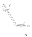
- FIG. 4 illustrates movement of the handle to reduce the sizes of the outer and inner rings, in order to adjust the size of the rings around the tissues to be excised.
- FIG. 5 demonstrates the positioning of the instrument over the uterine fundus and cinched down over the cervix.
- FIG. 6 illustrates the pulling of the inner transection wire through the cervix.
- FIG. 7 illustrates the inner transection wire continuing to be pulled through the tissues and transecting through approximately half of the cervix.
- FIG. 8 demonstrates the inner transection wire almost completely pulled through the cervical tissue.
- FIG. 9 demonstrates the completed transection through the cervix, after the inner transection wire has been withdrawn through the tissues and into the cylinder. The stabilization ring is still in place over the cervix.
- FIG. 10 demonstrates the cervix released from the stabilization ring and the stabilization ring being withdrawn back into the cylinder.
- FIG. 11 demonstrates a second wire on the inner aspect of the outer ring that is exposed in only two separate areas, opposite from one another, in an area that would correspond to the location of the vascular supply to the uterus.
- FIG. 12 illustrates the inner wire being withdrawn through the tissues and into the cylinder.
- FIG. 13 illustrates a cross-section of an exemplary arrangement of the outer and inner rings.
- FIG. 14 shows a cross-section of another embodiment of the instrument, with a second wire that is within the outer ring, and is exposed circumferentially around the inner aspect of the outer ring.
- FIG. 15 shows a cross-section of another embodiment of the instrument, with a second wire that is within the outer ring, but is electrically exposed only on two opposite sides of the ring.
- FIG. 16 illustrates the presence of smoke aspiration holes located around the circumference of the instrument, attached to a channel that travels up the shaft of the cylindrical instrument.
- FIG. 17 illustrates another embodiment of the inner transection wire, which may be partially insulated proximally.
- FIG. 1 illustrates the general design of the instrument. It may include a cylindrical hollow tube ( 1 ), a handle ( 2 ) and two rings that are deployed out from the end of the cylindrical tube: an outer insulated stabilization ring ( 3 ) which is thin but wide (as a ribbon), and an inner transection wire ( 4 ), which connects to a wire that runs up the cylinder, out through the handle and connects to an electrical generator. Pushing in on the handle deploys the two rings together out from the end of the cylinder and pulling back on the handle draws the rings back into the cylinder.
- an outer insulated stabilization ring 3
- an inner transection wire 4
- FIG. 2 depicts the device in the open position with outer ring ( 3 ) and inner wire ( 4 ).
- the deployment of the two rings would typically be performed once the instrument is placed in the body in order to place the rings over the tissue to be excised.
- FIG. 3 illustrates the ability of the outer and inner rings to bend after insertion in the abdomen. This might be required in order to position the rings over the uterine fundus and down to the level of the internal cervical os, which would be a typical placement for performing a supracervical hysterectomy.
- FIG. 4 demonstrates how the handle is pulled back in order to reduce the size of the outer and inner rings.
- the inner wire is attached to the handle so that both rings can be deployed and withdrawn together; however, the inner wire can be detached from the handle so that the inner wire can be drawn back independently of the outer wire for transection of tissues while maintaining the position of the outer stabilization ring on the cervix.
- FIG. 5 demonstrates the placement of the double rings at the level of the internal cervical os after the rings have been placed over the uterus ( 5 ).
- FIG. 6 illustrates the inner wire ( 4 ), having been separated from the handle, being pulled and withdrawn through the cervix while an electrical current is applied to the wire.
- FIG. 7 illustrates the inner wire ( 4 ) continuing to be pulled through the tissues with an electrical current applied. Before this step begins, the surgeon removes any uterine manipulator that has been placed into the cervix.
- FIG. 8 illustrates the inner wire ( 4 ) has now been completely pulled through the tissue and has transected the uterine fundus.
- FIG. 9 demonstrates the uterus ( 5 ) having been completely transected and the endocervical canal is now visible ( 6 ).
- the stabilization ring ( 3 ) is still around the cervix.
- FIG. 10 demonstrates the endocervical canal ( 6 ) that can be visualized on the cervix ( 7 ) and on the uterine specimen.
- the outer stabilization ring ( 3 ) is being withdrawn back into the cylinder.
- FIG. 11 demonstrates another embodiment of the instrument, where an exposed wire or other conductive material ( 8 ) is present on opposite sides of the outer ring, and is used to create a bipolar current with the inner wire ( 4 ) to coagulate vessels, such as the uterine vessels during the supracervical hysterectomy.
- the wire ( 8 ) may be exposed at other or additional positions around the ring or may be exposed around the entire ring.
- FIG. 12 demonstrates the inner wire ( 4 ) being pulled through tissue with monopolar cautery after bipolar cauterization of the vessels with both the inner wire ( 4 ) and the outer ring conductive elements ( 8 ).
- FIG. 13 is a cross-section of one embodiment of the device with the inner ring ( 4 ) located within a groove ( 9 ) of the outer insulated ring ( 3 ).
- FIG. 14 is a cross-section of another embodiment of the device with the inner ring ( 4 ), and the outer ring containing a conductive element ( 8 ) that is located circumferentially within or attached to the outer ring.
- FIG. 15 is a cross-section of another embodiment of the device with the outer ring conductive elements ( 8 ) located at opposite ends of the outer ring.
- FIG. 16 demonstrates another embodiment of the outer ring, with a series of holes located on the outer ring ( 10 ) that are connected to a channel ( 11 ) that comes out from the handle of the instrument and is connected to suction (in order to evacuate smoke from the area during electrocoagulation of tissue, either with monopolar or bipolar energy) or to a fluid source for infusion of gas or liquid into the surgical site.
- FIG. 17 illustrates another embodiment of the inner transection wire, whereby some part of the proximal wire is insulated ( 12 ).
- the device itself can be used and/or is adaptable to be used with a wide variety of other anatomic portions, such as the gallbladder, liver, lung, pancreas, spleen, kidney, muscle, and bone.
- the device may also be used to remove pathological structures, such as polyps and neoplasms.
- Devices customized for particular anatomic regions or uses can be provided with predetermined sizes for the ring ( 3 ), wire ( 4 ), and/or element(s) ( 8 ), and optionally with predetermined number and position of element(s) ( 8 ).
Abstract
Description
Claims (20)
Priority Applications (3)
| Application Number | Priority Date | Filing Date | Title |
|---|---|---|---|
| US11/770,714 US7806894B1 (en) | 2006-06-28 | 2007-06-28 | Hemostasis and transection of tissue |
| US12/897,736 US9095369B1 (en) | 2005-06-27 | 2010-10-04 | Hemostasis and transection of tissue |
| US14/816,436 US20160184009A1 (en) | 2005-06-27 | 2015-08-03 | Hemostasis and transection of tissue |
Applications Claiming Priority (2)
| Application Number | Priority Date | Filing Date | Title |
|---|---|---|---|
| US80603106P | 2006-06-28 | 2006-06-28 | |
| US11/770,714 US7806894B1 (en) | 2006-06-28 | 2007-06-28 | Hemostasis and transection of tissue |
Related Child Applications (1)
| Application Number | Title | Priority Date | Filing Date |
|---|---|---|---|
| US12/897,736 Continuation US9095369B1 (en) | 2005-06-27 | 2010-10-04 | Hemostasis and transection of tissue |
Publications (1)
| Publication Number | Publication Date |
|---|---|
| US7806894B1 true US7806894B1 (en) | 2010-10-05 |
Family
ID=42797709
Family Applications (3)
| Application Number | Title | Priority Date | Filing Date |
|---|---|---|---|
| US11/770,714 Expired - Fee Related US7806894B1 (en) | 2005-06-27 | 2007-06-28 | Hemostasis and transection of tissue |
| US12/897,736 Expired - Fee Related US9095369B1 (en) | 2005-06-27 | 2010-10-04 | Hemostasis and transection of tissue |
| US14/816,436 Abandoned US20160184009A1 (en) | 2005-06-27 | 2015-08-03 | Hemostasis and transection of tissue |
Family Applications After (2)
| Application Number | Title | Priority Date | Filing Date |
|---|---|---|---|
| US12/897,736 Expired - Fee Related US9095369B1 (en) | 2005-06-27 | 2010-10-04 | Hemostasis and transection of tissue |
| US14/816,436 Abandoned US20160184009A1 (en) | 2005-06-27 | 2015-08-03 | Hemostasis and transection of tissue |
Country Status (1)
| Country | Link |
|---|---|
| US (3) | US7806894B1 (en) |
Cited By (13)
| Publication number | Priority date | Publication date | Assignee | Title |
|---|---|---|---|---|
| US20100274291A1 (en) * | 2009-04-23 | 2010-10-28 | Custom Spine, Inc. | Spinal Fixation Mechanism |
| US8323278B2 (en) | 2010-12-06 | 2012-12-04 | Soulor Surgical, Inc. | Apparatus for treating a portion of a reproductive system and related methods of use |
| US20140276809A1 (en) * | 2013-03-14 | 2014-09-18 | Boston Scientific Scimed, Inc. | Resection device with support mechanism and related methods of use |
| US9011433B2 (en) | 2013-03-15 | 2015-04-21 | Gyrus Acmi, Inc. | Bipolar colpotomy device |
| US9144454B2 (en) | 2013-11-12 | 2015-09-29 | Gyrus Acmi, Inc. | Electrosurgical colpotomy device |
| JP2016150044A (en) * | 2015-02-16 | 2016-08-22 | 国立大学法人鳥取大学 | Endoscopic treatment instrument |
| US9707012B2 (en) | 2015-07-31 | 2017-07-18 | Polygon Medical, Inc. | Polypectomy systems, devices, and methods |
| US20180325538A1 (en) * | 2017-05-12 | 2018-11-15 | Ellenial Surgical, LLC | Fecalith removal system |
| USD847992S1 (en) | 2017-06-27 | 2019-05-07 | Polygon Medical, Inc. | Medical device handle |
| US10285731B2 (en) | 2017-06-14 | 2019-05-14 | Polygon Medical, Inc. | Polypectomy systems, devices, and methods |
| WO2019202764A1 (en) * | 2018-04-20 | 2019-10-24 | オリンパス株式会社 | Treatment tool |
| CN110711026A (en) * | 2014-09-05 | 2020-01-21 | 埃派克斯医疗公司 | Electrosurgical snare device |
| US11324510B2 (en) * | 2013-12-30 | 2022-05-10 | Atricure, Inc. | Systems and methods for left atrial appendage closure |
Families Citing this family (1)
| Publication number | Priority date | Publication date | Assignee | Title |
|---|---|---|---|---|
| WO2023014919A1 (en) * | 2021-08-05 | 2023-02-09 | Endovision Foundation | Endoscopic loop systems and methods of use |
Citations (7)
| Publication number | Priority date | Publication date | Assignee | Title |
|---|---|---|---|---|
| US5318564A (en) * | 1992-05-01 | 1994-06-07 | Hemostatic Surgery Corporation | Bipolar surgical snare and methods of use |
| US5611803A (en) * | 1994-12-22 | 1997-03-18 | Urohealth Systems, Inc. | Tissue segmentation device |
| US5746747A (en) | 1994-05-13 | 1998-05-05 | Mckeating; John A. | Polypectomy instrument |
| US6616659B1 (en) | 2001-07-27 | 2003-09-09 | Starion Instruments Corporation | Polypectomy device and method |
| US6852108B2 (en) | 2002-05-14 | 2005-02-08 | Spiration, Inc. | Apparatus and method for resecting and removing selected body tissue from a site inside a patient |
| US7087053B2 (en) * | 2004-05-27 | 2006-08-08 | St. Jude Medical, Atrial Fibrillation Division, Inc. | Catheter with bifurcated, collapsible tip for sensing and ablating |
| US20070027450A1 (en) * | 2005-07-28 | 2007-02-01 | Forcept, Inc. | Devices and methods for mobilization of the uterus |
Family Cites Families (5)
| Publication number | Priority date | Publication date | Assignee | Title |
|---|---|---|---|---|
| US4493320A (en) * | 1982-04-02 | 1985-01-15 | Treat Michael R | Bipolar electrocautery surgical snare |
| JP3256540B2 (en) * | 1990-10-09 | 2002-02-12 | メッドトロニック・インコーポレイテッド | Device or device for manipulating the target object |
| US5158561A (en) * | 1992-03-23 | 1992-10-27 | Everest Medical Corporation | Monopolar polypectomy snare with coagulation electrode |
| US7147635B2 (en) * | 2004-01-29 | 2006-12-12 | Ethicon, Inc. | Bipolar electrosurgical snare |
| US7618437B2 (en) * | 2005-07-15 | 2009-11-17 | Granit Medical Innovation, Llc | Endoscope retrieval instrument assembly |
-
2007
- 2007-06-28 US US11/770,714 patent/US7806894B1/en not_active Expired - Fee Related
-
2010
- 2010-10-04 US US12/897,736 patent/US9095369B1/en not_active Expired - Fee Related
-
2015
- 2015-08-03 US US14/816,436 patent/US20160184009A1/en not_active Abandoned
Patent Citations (7)
| Publication number | Priority date | Publication date | Assignee | Title |
|---|---|---|---|---|
| US5318564A (en) * | 1992-05-01 | 1994-06-07 | Hemostatic Surgery Corporation | Bipolar surgical snare and methods of use |
| US5746747A (en) | 1994-05-13 | 1998-05-05 | Mckeating; John A. | Polypectomy instrument |
| US5611803A (en) * | 1994-12-22 | 1997-03-18 | Urohealth Systems, Inc. | Tissue segmentation device |
| US6616659B1 (en) | 2001-07-27 | 2003-09-09 | Starion Instruments Corporation | Polypectomy device and method |
| US6852108B2 (en) | 2002-05-14 | 2005-02-08 | Spiration, Inc. | Apparatus and method for resecting and removing selected body tissue from a site inside a patient |
| US7087053B2 (en) * | 2004-05-27 | 2006-08-08 | St. Jude Medical, Atrial Fibrillation Division, Inc. | Catheter with bifurcated, collapsible tip for sensing and ablating |
| US20070027450A1 (en) * | 2005-07-28 | 2007-02-01 | Forcept, Inc. | Devices and methods for mobilization of the uterus |
Cited By (22)
| Publication number | Priority date | Publication date | Assignee | Title |
|---|---|---|---|---|
| US8083780B2 (en) * | 2009-04-23 | 2011-12-27 | Custom Spine, Inc. | Spinal fixation mechanism |
| US20100274291A1 (en) * | 2009-04-23 | 2010-10-28 | Custom Spine, Inc. | Spinal Fixation Mechanism |
| US8323278B2 (en) | 2010-12-06 | 2012-12-04 | Soulor Surgical, Inc. | Apparatus for treating a portion of a reproductive system and related methods of use |
| US8608738B2 (en) | 2010-12-06 | 2013-12-17 | Soulor Surgical, Inc. | Apparatus for treating a portion of a reproductive system and related methods of use |
| US11627990B2 (en) | 2010-12-06 | 2023-04-18 | Gyrus Acmi, Inc. | Apparatus for treating a portion of a reproductive system and related methods of use |
| US10034687B2 (en) | 2010-12-06 | 2018-07-31 | Surgigyn, Inc. | Apparatus for treating a portion of a reproductive system and related methods of use |
| US9554821B2 (en) * | 2013-03-14 | 2017-01-31 | Boston Scientific Scimed, Inc. | Resection device with support mechanism and related methods of use |
| US20140276809A1 (en) * | 2013-03-14 | 2014-09-18 | Boston Scientific Scimed, Inc. | Resection device with support mechanism and related methods of use |
| US9011433B2 (en) | 2013-03-15 | 2015-04-21 | Gyrus Acmi, Inc. | Bipolar colpotomy device |
| US9144454B2 (en) | 2013-11-12 | 2015-09-29 | Gyrus Acmi, Inc. | Electrosurgical colpotomy device |
| US11324510B2 (en) * | 2013-12-30 | 2022-05-10 | Atricure, Inc. | Systems and methods for left atrial appendage closure |
| CN110711026A (en) * | 2014-09-05 | 2020-01-21 | 埃派克斯医疗公司 | Electrosurgical snare device |
| US20200188010A1 (en) * | 2014-09-05 | 2020-06-18 | Apyx Medical Corporation | Electrosurgical snare device |
| CN110711026B (en) * | 2014-09-05 | 2023-02-28 | 埃派克斯医疗公司 | Electrosurgical snare device |
| JP2016150044A (en) * | 2015-02-16 | 2016-08-22 | 国立大学法人鳥取大学 | Endoscopic treatment instrument |
| US9707012B2 (en) | 2015-07-31 | 2017-07-18 | Polygon Medical, Inc. | Polypectomy systems, devices, and methods |
| US20180325538A1 (en) * | 2017-05-12 | 2018-11-15 | Ellenial Surgical, LLC | Fecalith removal system |
| US10285731B2 (en) | 2017-06-14 | 2019-05-14 | Polygon Medical, Inc. | Polypectomy systems, devices, and methods |
| US11278320B2 (en) | 2017-06-14 | 2022-03-22 | Polygon Medical, Inc. | Polypectomy systems, devices, and methods |
| USD847992S1 (en) | 2017-06-27 | 2019-05-07 | Polygon Medical, Inc. | Medical device handle |
| USD947378S1 (en) | 2017-06-27 | 2022-03-29 | Polygon Medical, Inc. | Medical device handle |
| WO2019202764A1 (en) * | 2018-04-20 | 2019-10-24 | オリンパス株式会社 | Treatment tool |
Also Published As
| Publication number | Publication date |
|---|---|
| US20160184009A1 (en) | 2016-06-30 |
| US9095369B1 (en) | 2015-08-04 |
Similar Documents
| Publication | Publication Date | Title |
|---|---|---|
| US7806894B1 (en) | Hemostasis and transection of tissue | |
| US20230240717A1 (en) | Apparatus for treating a portion of a reproductive system and related methods of use | |
| US8747413B2 (en) | Uterine sealer | |
| US7135018B2 (en) | Electrosurgical instrument and method for transecting an organ | |
| EP3068323B1 (en) | Electrosurgical colpotomy device | |
| US8025670B2 (en) | Methods and apparatus for natural orifice vaginal hysterectomy | |
| US6428539B1 (en) | Apparatus and method for minimally invasive surgery using rotational cutting tool | |
| US7147635B2 (en) | Bipolar electrosurgical snare | |
| US7641651B2 (en) | Devices and methods for mobilization of the uterus | |
| US10039597B2 (en) | Surgical cutting instrument and related methods | |
| JP2008539980A (en) | Method and apparatus for performing surgery | |
| WO2009073619A2 (en) | Transcervical excision and removal of tissue | |
| JP2009501029A (en) | Transvaginal uterine artery occlusion | |
| US6346106B1 (en) | Instrument and method employing snare electrode windable about rotatable spool for minimally invasive electrosurgical resection | |
| WO2011140172A1 (en) | Method and system for intracavitary and extracavitary procedures | |
| WO2009072131A2 (en) | Prostatic capsulotomy for treatment of conditions | |
| GB2460242A (en) | Morcellating laparoscopic instrument with bipolar electrodes and double skin wall. | |
| EP3052039B1 (en) | Bipolar coagulation probe and snare | |
| AU2016228311B2 (en) | Apparatus for treating a portion of a reproductive system and related methods of use | |
| AU2015200349B2 (en) | Apparatus for treating a portion of a reproductive system and related methods of use | |
| WO2019142911A1 (en) | Endoscope treatment instrument | |
| McKernan et al. | New application of bipolar coagulation in laparoscopic surgery | |
| JP2507871Y2 (en) | Electrosurgical device electrode | |
| KR20120065863A (en) | Laparoscope surgical instrument | |
| US11471213B2 (en) | Marchand advanced single port hysterectomy—a laparoscopic surgical technique |
Legal Events
| Date | Code | Title | Description |
|---|---|---|---|
| AS | Assignment |
Owner name: NEW ENGLAND ASSOCIATION OF GYNECOLOGIC LAPAROSCOPI Free format text: ASSIGNMENT OF ASSIGNORS INTEREST;ASSIGNORS:ROSENBLATT, PETER L.;DISCIULLO, ANTHONY J.;SIGNING DATES FROM 20100818 TO 20100829;REEL/FRAME:024903/0851 |
|
| FEPP | Fee payment procedure |
Free format text: PAYOR NUMBER ASSIGNED (ORIGINAL EVENT CODE: ASPN); ENTITY STATUS OF PATENT OWNER: SMALL ENTITY |
|
| AS | Assignment |
Owner name: ROSENBLATT ASSOCIATES. LLC, MASSACHUSETTS Free format text: ASSIGNMENT OF ASSIGNORS INTEREST;ASSIGNOR:NEW ENGLAND ASSOCIATION OF GYNECOLOGIC LAPAROSCOPISTS, LLP;REEL/FRAME:025879/0459 Effective date: 20110224 |
|
| REMI | Maintenance fee reminder mailed | ||
| FPAY | Fee payment |
Year of fee payment: 4 |
|
| SULP | Surcharge for late payment | ||
| FEPP | Fee payment procedure |
Free format text: MAINTENANCE FEE REMINDER MAILED (ORIGINAL EVENT CODE: REM.) |
|
| LAPS | Lapse for failure to pay maintenance fees |
Free format text: PATENT EXPIRED FOR FAILURE TO PAY MAINTENANCE FEES (ORIGINAL EVENT CODE: EXP.); ENTITY STATUS OF PATENT OWNER: SMALL ENTITY |
|
| STCH | Information on status: patent discontinuation |
Free format text: PATENT EXPIRED DUE TO NONPAYMENT OF MAINTENANCE FEES UNDER 37 CFR 1.362 |
|
| FP | Lapsed due to failure to pay maintenance fee |
Effective date: 20181005 |