US7802410B2 - Modular elements, network, supporting structure, construct - Google Patents
Modular elements, network, supporting structure, construct Download PDFInfo
- Publication number
- US7802410B2 US7802410B2 US12/067,697 US6769706A US7802410B2 US 7802410 B2 US7802410 B2 US 7802410B2 US 6769706 A US6769706 A US 6769706A US 7802410 B2 US7802410 B2 US 7802410B2
- Authority
- US
- United States
- Prior art keywords
- joint
- passages
- elements
- modular
- construction element
- Prior art date
- Legal status (The legal status is an assumption and is not a legal conclusion. Google has not performed a legal analysis and makes no representation as to the accuracy of the status listed.)
- Expired - Fee Related
Links
Images


Classifications
-
- E—FIXED CONSTRUCTIONS
- E04—BUILDING
- E04B—GENERAL BUILDING CONSTRUCTIONS; WALLS, e.g. PARTITIONS; ROOFS; FLOORS; CEILINGS; INSULATION OR OTHER PROTECTION OF BUILDINGS
- E04B2/00—Walls, e.g. partitions, for buildings; Wall construction with regard to insulation; Connections specially adapted to walls
- E04B2/02—Walls, e.g. partitions, for buildings; Wall construction with regard to insulation; Connections specially adapted to walls built-up from layers of building elements
- E04B2/14—Walls having cavities in, but not between, the elements, i.e. each cavity being enclosed by at least four sides forming part of one single element
- E04B2/26—Walls having cavities in, but not between, the elements, i.e. each cavity being enclosed by at least four sides forming part of one single element the walls being characterised by fillings in all cavities in order to form a wall construction
-
- E—FIXED CONSTRUCTIONS
- E04—BUILDING
- E04C—STRUCTURAL ELEMENTS; BUILDING MATERIALS
- E04C1/00—Building elements of block or other shape for the construction of parts of buildings
-
- E—FIXED CONSTRUCTIONS
- E04—BUILDING
- E04C—STRUCTURAL ELEMENTS; BUILDING MATERIALS
- E04C1/00—Building elements of block or other shape for the construction of parts of buildings
- E04C1/40—Building elements of block or other shape for the construction of parts of buildings built-up from parts of different materials, e.g. composed of layers of different materials or stones with filling material or with insulating inserts
- E04C1/41—Building elements of block or other shape for the construction of parts of buildings built-up from parts of different materials, e.g. composed of layers of different materials or stones with filling material or with insulating inserts composed of insulating material and load-bearing concrete, stone or stone-like material
Definitions
- the invention relates to modular elements made of insulating materials for constructions, provided with at least one network element in the interior; to a network obtained by connecting modular elements; to a supporting structure achieved by casting a hardening material in the network achieved by connecting the modular elements and joining them through the supporting structure, as well as to the process for obtaining thereof.
- the concrete panels are used in a wide range of applications in the civil engineering industry, the construction time being thus reduced.
- the pre-cast panels are manufactured by casting the concrete into forms (concrete forming. After hardening, the panels are vertically positioned at the construction site.
- the patent US 2002017070 describes an expanded plastic module intended for the building of a concrete wall structure, insulated by interconnecting the modules and filling them with concrete.
- the module is made of expanded polystyrene.
- Each module has the form of a rigid block, having an interior configuration designed to be filled with concrete. Additionally, for the increase of strength, a network of steel or plastic bars is being introduced inside the modules.
- the disadvantage of this technical solution consists in a high rate of concrete consumption, flow problems upon the placing of concrete, due to the internal passages, positioned perpendicularly along the vertical and horizontal line; also, a too complex construction and additional manual working, brought about by the network of bars.
- the patent WO 2005059264 relates to polyurethanes or polystyrene foams for concrete structures.
- the insulating blocks elements have an interior arrangement in the form of vertical cavities in a trapezoidal, circular, elliptical or parabolic shape.
- the structure obtained after the blocks have been filled with concrete has good strength properties and optimum heat insulation; moreover, the strength of the linear structure is inferior to the structures in which concrete is cast in several directions.
- the U.S. Pat. No. 4,942,707 describes ceiling or roof structures, based on a rigid insulation, provided with several cavities or passages that become molds for the concrete during its casting. Following the joining of structures in the form of a ceiling or a roof, concrete is to be cast in these cavities or passages.
- the disadvantage of this technical solution is the high rate of consumption of concrete; also, it may be applied only to ceilings and roofs.
- the problem solved by this invention is the achievement of a construction with a unitary structure of strength and appropriate heat insulation, without any elements of concrete forming, using a simple and cost effective procedure.
- the purpose of this invention is the achievement of a unitary supporting structure that would be suitable for constructions, through the casting of a hardening material in a unitary network, defined and formed through the connection of modular elements made of insulating materials.
- the modular element removes the previously mentioned disadvantages, as it has an interior network element made up of at least two main half-joint cavities and optionally it may have one or more secondary half-joint cavities, connected through vertical and oblique passages.
- the modular element removes the previously mentioned disadvantages, as it has an interior network element made up of two main half-joints and two secondary half-joint cavities, connected through vertical and oblique passages.
- the modular element removes the previously mentioned is disadvantages as it has an interior network element made up of four main half-joint cavities and two secondary half-joint cavities, connected through vertical and oblique passages.
- the modular element removes the previously mentioned disadvantages as it has an interior network element made up of four main half-joint cavities, connected through vertical and oblique passages.
- the modular element removes the previously mentioned disadvantages, as it has an interior network element made up of two main half-joint cavities, and a parallelepiped, connected through vertical, horizontal and oblique passages.
- the modular element removes the previously mentioned disadvantages as it has in the interior three main open passages, two of which parallel and one perpendicular to the other two.
- the modular elements removes the previously mentioned disadvantages as they have an odd number of joint elements and at least two joint elements, respectively, or four joint elements equally positioned in the upper and lower part.
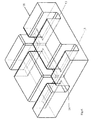
- the network obtained by assembling the modular elements removes the previously mentioned disadvantages as it is made up of main and secondary joints, connected trough vertical, horizontal and oblique passages.
- the unitary supporting structure removes the above mentioned disadvantages, as it is obtained by casting a material that will be harden in the unitary network for the entire construction.
- the construction removes the previously mentioned disadvantages as it is made up of a unitary supporting structure inside of an insulating structure, obtained by connecting the modular elements.
- the process for obtaining the construction according to the invention removes the disadvantages mentioned above as it consists of the following: connection of modular elements and the casting of material that hardens in the network defined through the connection of modular elements and the creation of a unitary supporting structure.
- the modular elements are made of synthetic foams based on polyurethanes, polyamides, polyethylene, polypropylene, polyvinyl chloride, polyvinylidene chloride, amino resins, phenolic resins, silicones, expanded polystyrene and sodium silicate.
- the network elements are joints having a cylindrical, spherical, prismatic or tapered form, connected through vertical, oblique or horizontal passages, as well as open passages which intersect each another perpendicularly.
- the material to be cast in the network according to the invention, in order to harden and form the supporting structure may be one of the following: concrete, reinforced concrete, polyester resins, epoxy resins, polyurethane resins.
- the construction procedure for one-floor building includes the connection of modular elements for the foundation, walls, ceiling, roof in a vault shape, and the cast of material in the network defined by specific modular elements: the material hardens and forms the supporting structure which is Unitary in the building assembly, but specific for each part of the building.
- FIG. 1 Modular element 1 having in interior a network element consisting of a main half-joint cavity 2 , a secondary half-joint cavity 3 connected through vertical passage 4 and oblique passages 5 and two-joint elements 6 .
- FIG. 2 Modular element 7 having in the interior a network element consisting of two main half-joints 2 , two secondary half-joint cavities 3 connected through vertical passages 4 and oblique passages 5 and four joint elements 6 .
- Modular element 8 having in the interior a network element consisting of four main half-joints 2 , two secondary half-joint cavities 3 connected through vertical passages 4 and oblique passages 5 and eight joint elements 6 .
- FIG. 4 Modular element 9 for the foundation having in the interior a network element consisting of four main half-joint cavity 2 connected through vertical passages 4 and oblique passages 5 and two joint elements 6 , an upper one and a lower one.
- FIG. 5 Modular element 10 for the corner, having in the interior two main half joints 2 , a parallelepiped 11 connected through vertical passages 4 and oblique passages 5 and horizontal passages 12 and four joint elements 6 .
- FIG. 6 Modular element 18 for the ceiling having in the interior three main open passages, two of which being parallel passages 13 and one passage 14 being perpendicular to the other two.
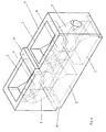
- FIG. 7 Construction consisting of modular elements, making up the foundation 15 , the wall 16 and the ceiling 17 .
- modular elements for wall FIG. 1 ), corner ( FIG. 4 ), foundation ( FIG. 5 ), ceiling ( FIG. 6 ) from fireproofed polyurethane foam, by injecting in mold and expanding at the dimensions of the mold.
- the modular elements have the following dimensions: the modular element for wall has the dimensions 120/60/30 cm with vertical passages of 16 cm in diameter, oblique passages of 12 cm in diameter and joint element of 20 cm; the modular element for corner has the dimensions 120/60/30 cm for one side and 60/60/30 cm for the other side, with vertical passages of 16 cm in diameter, oblique passages of 12 cm in diameter and joint element of 20 cm; the modular element for foundation has the dimensions of 120/60/60 cm with vertical passages of 20 cm in diameter, oblique passages of 14 cm in diameter and joint element of 20 cm; the modular element for ceiling has the dimensions 120/60/20 cm with passages of 15/15 cm.
- the strength of the wall at stress is 100 tons/meter.
Abstract
Description
-
- the achievement of a construction with a unitary structure of strength and appropriate heat insulation, without any elements of concrete forming, using a simple and cost effective procedure
- the construction is achieved in shorter time in comparison with traditional processes;
- the resistance of the construction is higher in comparison with other processes;
Claims (17)
Applications Claiming Priority (4)
| Application Number | Priority Date | Filing Date | Title |
|---|---|---|---|
| ROA200500806A RO123373B1 (en) | 2005-09-22 | 2005-09-22 | Modular elements, lattice, bearing structure, construction and process for making the same |
| ROA200500806 | 2005-09-22 | ||
| RO05-0806 | 2005-09-22 | ||
| PCT/RO2006/000016 WO2007081233A2 (en) | 2005-09-22 | 2006-08-07 | Modular elements, network, supporting structure, construction and process for obtaining thereof |
Publications (2)
| Publication Number | Publication Date |
|---|---|
| US20080250736A1 US20080250736A1 (en) | 2008-10-16 |
| US7802410B2 true US7802410B2 (en) | 2010-09-28 |
Family
ID=38256739
Family Applications (1)
| Application Number | Title | Priority Date | Filing Date |
|---|---|---|---|
| US12/067,697 Expired - Fee Related US7802410B2 (en) | 2005-09-22 | 2006-08-07 | Modular elements, network, supporting structure, construct |
Country Status (16)
| Country | Link |
|---|---|
| US (1) | US7802410B2 (en) |
| EP (1) | EP1926865B1 (en) |
| JP (1) | JP4733747B2 (en) |
| KR (1) | KR101079380B1 (en) |
| CN (1) | CN101268237A (en) |
| AU (1) | AU2006335382B2 (en) |
| CA (1) | CA2621224C (en) |
| EA (1) | EA012548B1 (en) |
| ES (1) | ES2647078T3 (en) |
| IL (1) | IL189909A (en) |
| NO (1) | NO20081598L (en) |
| NZ (1) | NZ567135A (en) |
| PL (1) | PL1926865T3 (en) |
| RO (1) | RO123373B1 (en) |
| UA (1) | UA92034C2 (en) |
| WO (1) | WO2007081233A2 (en) |
Cited By (7)
| Publication number | Priority date | Publication date | Assignee | Title |
|---|---|---|---|---|
| US20100287871A1 (en) * | 2009-05-12 | 2010-11-18 | Vanocur Refractories, L.L.C. | Corbel repairs of coke ovens |
| US20120282841A1 (en) * | 2011-05-04 | 2012-11-08 | Chih Shing Wei | Coupling Structure |
| US20140182221A1 (en) * | 2013-01-03 | 2014-07-03 | Tony Hicks | Thermal Barrier For Building Foundation Slab |
| US20160032554A1 (en) * | 2013-01-03 | 2016-02-04 | Tony Hicks | Insulating Device for Building Foundation Slab |
| US10058792B2 (en) * | 2015-06-25 | 2018-08-28 | Tibbo Technology, Inc. | Three-dimensional grid beam and construction set thereof |
| US11008752B1 (en) * | 2020-10-05 | 2021-05-18 | Juan Diego Castro | Insulating superblocks for constructing modular superblock assemblies |
| US11225804B1 (en) * | 2012-01-11 | 2022-01-18 | J.F.R. Enterprises Inc. | Sleeve support for a condenser |
Families Citing this family (13)
| Publication number | Priority date | Publication date | Assignee | Title |
|---|---|---|---|---|
| US7856773B2 (en) * | 2003-07-24 | 2010-12-28 | Wagdy Agaiby | All-in-one modular construction system |
| RO123557B1 (en) * | 2007-08-22 | 2013-08-30 | Laurenţiu-Dumitru Breaz | Modular element, network, bearing structure and construction made therewith |
| DE102009011616A1 (en) * | 2009-03-04 | 2010-09-09 | Schöck Bauteile GmbH | Shuttering apparatus and method for creating a recess during casting of a component |
| RO129241B1 (en) | 2012-07-30 | 2017-08-30 | Laurenţiu Dumitru Breaz | Storage basin and method for making the same |
| WO2014057175A1 (en) * | 2012-10-12 | 2014-04-17 | Christophe Portugues | Construction panel made from an insulating material |
| CA2854048C (en) * | 2013-06-07 | 2017-04-25 | Oldcastle Architectural, Inc. | Concrete masonry unit blocks with dimensional lumber pockets and assemblies of blocks and lumber |
| FR3016908B1 (en) * | 2014-01-28 | 2017-05-19 | H&H Tech | INSULATING CONSTRUCTION ELEMENT AND METHOD FOR MANUFACTURING THE SAME |
| US9194125B1 (en) * | 2014-09-12 | 2015-11-24 | Sergei V. Romanenko | Construction component having embedded internal support structures to provide enhanced structural reinforcement and improved ease of construction therewith |
| CN105484389B (en) * | 2014-09-21 | 2017-12-22 | 河南龙成重型钢结构有限公司 | A kind of steel structure shear wall structure |
| RO131503B1 (en) * | 2015-05-12 | 2021-04-29 | Laurenţiu Dumitru Breaz | Precast block for constructions, modular element with optimized geometry, modular element manufacturing process, construction, process for carrying out a construction by assembling said modular elements |
| CN105064599B (en) * | 2015-09-15 | 2018-08-07 | 李春福 | Scissors lattice building-block and application |
| KR102190324B1 (en) * | 2018-11-12 | 2020-12-11 | 김태명 | A Set of Assemble-able Bricks |
| WO2023249504A1 (en) * | 2022-06-14 | 2023-12-28 | Breaz Laureniu Dumitru | Modular building elements |
Citations (45)
| Publication number | Priority date | Publication date | Assignee | Title |
|---|---|---|---|---|
| US314022A (en) * | 1885-03-17 | Brick | ||
| US756300A (en) * | 1903-12-03 | 1904-04-05 | Robert L Underwood | Ventilating building-block. |
| US1216840A (en) * | 1915-10-29 | 1917-02-20 | Embossing Company | Toy building-block. |
| US1524146A (en) * | 1923-04-30 | 1925-01-27 | Murray Richard | Wall construction for buildings |
| US1649780A (en) * | 1926-04-10 | 1927-11-15 | Robbins Isaac | Building block |
| US2493435A (en) * | 1946-05-31 | 1950-01-03 | Alcide J Arehambault | Building block |
| US2703487A (en) * | 1949-09-30 | 1955-03-08 | Ossoinack Andrea | Interlocking hollow building block |
| US2720779A (en) * | 1948-02-02 | 1955-10-18 | Henry J Earnest | Building block |
| US2843971A (en) * | 1955-08-09 | 1958-07-22 | Joseph G Gardellin | Construction toy block |
| US3232017A (en) * | 1963-02-07 | 1966-02-01 | Architectural Res Corp | Insulated structural panel with synthetic foam core and ornamental facing of visiblediscrete particulate material |
| US3430404A (en) * | 1967-03-20 | 1969-03-04 | George B Muse | Apertured wall construction |
| US3546833A (en) * | 1968-10-08 | 1970-12-15 | Arnold Perreton | Insulated building block construction |
| US3681870A (en) * | 1971-01-27 | 1972-08-08 | Childcraft Education Corp | Construction toy and a block construction therefor |
| DE2156006A1 (en) | 1971-11-11 | 1973-07-26 | Fred Konzuch | CONCRETE FRAMEWORK (DIAGONAL ARRANGEMENT) WITH HARD FOAM OR. LIGHTWEIGHT FORMING ELEMENTS WHICH ARE FILLING, PLASTERING AND INSULATING PARTS AT THE SAME TIME |
| US3766699A (en) * | 1971-06-04 | 1973-10-23 | A Dinkel | Constructional assembly, e. g. for constructing buildings, containers and vehicle bodies |
| US3890751A (en) * | 1974-03-11 | 1975-06-24 | Plasticrete Corp | Post hole block |
| US4326354A (en) * | 1977-03-24 | 1982-04-27 | Hagberg Carl E | Recreational kit for constructing objects |
| US4532745A (en) * | 1981-12-14 | 1985-08-06 | Core-Form | Channel and foam block wall construction |
| US4964833A (en) * | 1989-06-02 | 1990-10-23 | Mass-Set Kabushiki Kaisha | Toy construction blocks with connectors |
| US4996813A (en) * | 1989-09-21 | 1991-03-05 | Kliethermes Jr John C | Sound block |
| US5003746A (en) * | 1988-11-07 | 1991-04-02 | Structural Block Systems, Inc. | Arcuate and curvilinear assemblies comprising tandemly arranged building blocks having degrees of rotation |
| JPH04155040A (en) * | 1990-10-18 | 1992-05-28 | Iwao Kinoshita | Woody block for forming wall |
| US5350256A (en) * | 1991-11-26 | 1994-09-27 | Westblock Products, Inc. | Interlocking retaining walls blocks and system |
| US5487623A (en) * | 1993-03-31 | 1996-01-30 | Societe Civile Des Brevets Henri C. Vidal | Modular block retaining wall construction and components |
| US5488806A (en) * | 1993-09-09 | 1996-02-06 | Melnick; David W. | Block forms for receiving concrete |
| US5540525A (en) * | 1994-06-06 | 1996-07-30 | The Tensar Corporation | Modular block retaining wall system and method of constructing same |
| US5560171A (en) * | 1994-06-02 | 1996-10-01 | Mccoy; John R. | Stackable construction blocks |
| US5562519A (en) * | 1994-08-10 | 1996-10-08 | Loewenton; Edward | Panel, dowel and block construction kit |
| US5566521A (en) * | 1994-08-10 | 1996-10-22 | Andrews; Richard E. | Building structure and method |
| US5586841A (en) * | 1993-03-31 | 1996-12-24 | Societe Civile Des Brevets Henri Vidal | Dual purpose modular block for construction of retaining walls |
| US5704781A (en) * | 1994-09-17 | 1998-01-06 | Riedhammer Gmbh And Co. Kg | Refractory wall brick for a heating channel of a ring pit furnace |
| US5839243A (en) * | 1996-09-13 | 1998-11-24 | New Energy Wall Systems, Inc. | Interlocking and insulated form pattern assembly for creating a wall structure for receiving poured concrete |
| US5924247A (en) * | 1996-05-29 | 1999-07-20 | Lott's Concrete Products, Inc. | Lightweight structural panel configured to receive poured concrete and used in wall construction |
| US5950397A (en) * | 1994-12-20 | 1999-09-14 | Mary Rowena Ginn And Francis John Wood | Building panels |
| US5966889A (en) * | 1997-07-07 | 1999-10-19 | Zinner; Shaul | After wet adhesion building block system |
| US5992119A (en) * | 1997-10-17 | 1999-11-30 | Rokhlin; Zinoviy | Construction block, and a structure provided with the same |
| WO2000079068A1 (en) | 1999-06-22 | 2000-12-28 | Jaime Enrique Jimenez Sanchez | Construction brick formed of an external expanded polystyrene box and a polystyrene-lightened concrete core |
| US6253519B1 (en) * | 1999-10-12 | 2001-07-03 | Aaron E. Daniel | Construction block |
| US6318041B1 (en) * | 1996-12-11 | 2001-11-20 | Starfoam Manufacturing, Inc. | Panel system with moisture removal |
| US20030029118A1 (en) * | 2001-08-09 | 2003-02-13 | Grau Jaime Alberto | Set of modular blocks for the construction of internal and external walls of buildings |
| US6588168B2 (en) * | 2001-04-17 | 2003-07-08 | Donald L. Walters | Construction blocks and structures therefrom |
| US6691485B1 (en) * | 2003-01-17 | 2004-02-17 | Leo Ostrovsky | Universal modular building block and a method and structures based on the use of the aforementioned block |
| US6705057B2 (en) * | 2001-03-06 | 2004-03-16 | Smyer, Iii Sidney W. | Modular block system and method of construction |
| US7063481B2 (en) * | 2003-08-13 | 2006-06-20 | Trull Scott E | Connector block for modular construction and object fabricated therefrom |
| US20060185308A1 (en) * | 2005-02-22 | 2006-08-24 | Youth Toy Enterprise Co., Ltd. | Building block |
Family Cites Families (3)
| Publication number | Priority date | Publication date | Assignee | Title |
|---|---|---|---|---|
| AT291498B (en) * | 1965-11-12 | 1971-07-12 | Markus Ing Stracke | Component |
| JP3072740B2 (en) * | 1988-03-28 | 2000-08-07 | 株式会社リコー | Bubble jet type liquid jet recording device |
| JP2604380Y2 (en) * | 1991-08-12 | 2000-05-08 | 三菱化学フォームプラスティック株式会社 | Construction member for railway station platform and structure using the same |
-
2005
- 2005-09-22 RO ROA200500806A patent/RO123373B1/en unknown
-
2006
- 2006-07-08 UA UAA200805155A patent/UA92034C2/en unknown
- 2006-08-07 PL PL06849238T patent/PL1926865T3/en unknown
- 2006-08-07 CA CA2621224A patent/CA2621224C/en not_active Expired - Fee Related
- 2006-08-07 AU AU2006335382A patent/AU2006335382B2/en not_active Ceased
- 2006-08-07 CN CNA2006800349285A patent/CN101268237A/en active Pending
- 2006-08-07 NZ NZ567135A patent/NZ567135A/en not_active IP Right Cessation
- 2006-08-07 EP EP06849238.8A patent/EP1926865B1/en active Active
- 2006-08-07 ES ES06849238.8T patent/ES2647078T3/en active Active
- 2006-08-07 JP JP2008532182A patent/JP4733747B2/en not_active Expired - Fee Related
- 2006-08-07 WO PCT/RO2006/000016 patent/WO2007081233A2/en active Application Filing
- 2006-08-07 KR KR1020087009428A patent/KR101079380B1/en active IP Right Grant
- 2006-08-07 EA EA200800877A patent/EA012548B1/en not_active IP Right Cessation
- 2006-08-07 US US12/067,697 patent/US7802410B2/en not_active Expired - Fee Related
-
2008
- 2008-03-04 IL IL189909A patent/IL189909A/en not_active IP Right Cessation
- 2008-03-31 NO NO20081598A patent/NO20081598L/en not_active Application Discontinuation
Patent Citations (45)
| Publication number | Priority date | Publication date | Assignee | Title |
|---|---|---|---|---|
| US314022A (en) * | 1885-03-17 | Brick | ||
| US756300A (en) * | 1903-12-03 | 1904-04-05 | Robert L Underwood | Ventilating building-block. |
| US1216840A (en) * | 1915-10-29 | 1917-02-20 | Embossing Company | Toy building-block. |
| US1524146A (en) * | 1923-04-30 | 1925-01-27 | Murray Richard | Wall construction for buildings |
| US1649780A (en) * | 1926-04-10 | 1927-11-15 | Robbins Isaac | Building block |
| US2493435A (en) * | 1946-05-31 | 1950-01-03 | Alcide J Arehambault | Building block |
| US2720779A (en) * | 1948-02-02 | 1955-10-18 | Henry J Earnest | Building block |
| US2703487A (en) * | 1949-09-30 | 1955-03-08 | Ossoinack Andrea | Interlocking hollow building block |
| US2843971A (en) * | 1955-08-09 | 1958-07-22 | Joseph G Gardellin | Construction toy block |
| US3232017A (en) * | 1963-02-07 | 1966-02-01 | Architectural Res Corp | Insulated structural panel with synthetic foam core and ornamental facing of visiblediscrete particulate material |
| US3430404A (en) * | 1967-03-20 | 1969-03-04 | George B Muse | Apertured wall construction |
| US3546833A (en) * | 1968-10-08 | 1970-12-15 | Arnold Perreton | Insulated building block construction |
| US3681870A (en) * | 1971-01-27 | 1972-08-08 | Childcraft Education Corp | Construction toy and a block construction therefor |
| US3766699A (en) * | 1971-06-04 | 1973-10-23 | A Dinkel | Constructional assembly, e. g. for constructing buildings, containers and vehicle bodies |
| DE2156006A1 (en) | 1971-11-11 | 1973-07-26 | Fred Konzuch | CONCRETE FRAMEWORK (DIAGONAL ARRANGEMENT) WITH HARD FOAM OR. LIGHTWEIGHT FORMING ELEMENTS WHICH ARE FILLING, PLASTERING AND INSULATING PARTS AT THE SAME TIME |
| US3890751A (en) * | 1974-03-11 | 1975-06-24 | Plasticrete Corp | Post hole block |
| US4326354A (en) * | 1977-03-24 | 1982-04-27 | Hagberg Carl E | Recreational kit for constructing objects |
| US4532745A (en) * | 1981-12-14 | 1985-08-06 | Core-Form | Channel and foam block wall construction |
| US5003746A (en) * | 1988-11-07 | 1991-04-02 | Structural Block Systems, Inc. | Arcuate and curvilinear assemblies comprising tandemly arranged building blocks having degrees of rotation |
| US4964833A (en) * | 1989-06-02 | 1990-10-23 | Mass-Set Kabushiki Kaisha | Toy construction blocks with connectors |
| US4996813A (en) * | 1989-09-21 | 1991-03-05 | Kliethermes Jr John C | Sound block |
| JPH04155040A (en) * | 1990-10-18 | 1992-05-28 | Iwao Kinoshita | Woody block for forming wall |
| US5350256A (en) * | 1991-11-26 | 1994-09-27 | Westblock Products, Inc. | Interlocking retaining walls blocks and system |
| US5487623A (en) * | 1993-03-31 | 1996-01-30 | Societe Civile Des Brevets Henri C. Vidal | Modular block retaining wall construction and components |
| US5586841A (en) * | 1993-03-31 | 1996-12-24 | Societe Civile Des Brevets Henri Vidal | Dual purpose modular block for construction of retaining walls |
| US5488806A (en) * | 1993-09-09 | 1996-02-06 | Melnick; David W. | Block forms for receiving concrete |
| US5560171A (en) * | 1994-06-02 | 1996-10-01 | Mccoy; John R. | Stackable construction blocks |
| US5540525A (en) * | 1994-06-06 | 1996-07-30 | The Tensar Corporation | Modular block retaining wall system and method of constructing same |
| US5562519A (en) * | 1994-08-10 | 1996-10-08 | Loewenton; Edward | Panel, dowel and block construction kit |
| US5566521A (en) * | 1994-08-10 | 1996-10-22 | Andrews; Richard E. | Building structure and method |
| US5704781A (en) * | 1994-09-17 | 1998-01-06 | Riedhammer Gmbh And Co. Kg | Refractory wall brick for a heating channel of a ring pit furnace |
| US5950397A (en) * | 1994-12-20 | 1999-09-14 | Mary Rowena Ginn And Francis John Wood | Building panels |
| US5924247A (en) * | 1996-05-29 | 1999-07-20 | Lott's Concrete Products, Inc. | Lightweight structural panel configured to receive poured concrete and used in wall construction |
| US5839243A (en) * | 1996-09-13 | 1998-11-24 | New Energy Wall Systems, Inc. | Interlocking and insulated form pattern assembly for creating a wall structure for receiving poured concrete |
| US6318041B1 (en) * | 1996-12-11 | 2001-11-20 | Starfoam Manufacturing, Inc. | Panel system with moisture removal |
| US5966889A (en) * | 1997-07-07 | 1999-10-19 | Zinner; Shaul | After wet adhesion building block system |
| US5992119A (en) * | 1997-10-17 | 1999-11-30 | Rokhlin; Zinoviy | Construction block, and a structure provided with the same |
| WO2000079068A1 (en) | 1999-06-22 | 2000-12-28 | Jaime Enrique Jimenez Sanchez | Construction brick formed of an external expanded polystyrene box and a polystyrene-lightened concrete core |
| US6253519B1 (en) * | 1999-10-12 | 2001-07-03 | Aaron E. Daniel | Construction block |
| US6705057B2 (en) * | 2001-03-06 | 2004-03-16 | Smyer, Iii Sidney W. | Modular block system and method of construction |
| US6588168B2 (en) * | 2001-04-17 | 2003-07-08 | Donald L. Walters | Construction blocks and structures therefrom |
| US20030029118A1 (en) * | 2001-08-09 | 2003-02-13 | Grau Jaime Alberto | Set of modular blocks for the construction of internal and external walls of buildings |
| US6691485B1 (en) * | 2003-01-17 | 2004-02-17 | Leo Ostrovsky | Universal modular building block and a method and structures based on the use of the aforementioned block |
| US7063481B2 (en) * | 2003-08-13 | 2006-06-20 | Trull Scott E | Connector block for modular construction and object fabricated therefrom |
| US20060185308A1 (en) * | 2005-02-22 | 2006-08-24 | Youth Toy Enterprise Co., Ltd. | Building block |
Cited By (10)
| Publication number | Priority date | Publication date | Assignee | Title |
|---|---|---|---|---|
| US20100287871A1 (en) * | 2009-05-12 | 2010-11-18 | Vanocur Refractories, L.L.C. | Corbel repairs of coke ovens |
| US8266853B2 (en) * | 2009-05-12 | 2012-09-18 | Vanocur Refractories Llc | Corbel repairs of coke ovens |
| US8640635B2 (en) * | 2009-05-12 | 2014-02-04 | Vanocur Refractories, L.L.C. | Corbel repairs of coke ovens |
| US20120282841A1 (en) * | 2011-05-04 | 2012-11-08 | Chih Shing Wei | Coupling Structure |
| US8808051B2 (en) * | 2011-05-04 | 2014-08-19 | Grace-Comp Systems, Ltd. | Coupling structure |
| US11225804B1 (en) * | 2012-01-11 | 2022-01-18 | J.F.R. Enterprises Inc. | Sleeve support for a condenser |
| US20140182221A1 (en) * | 2013-01-03 | 2014-07-03 | Tony Hicks | Thermal Barrier For Building Foundation Slab |
| US20160032554A1 (en) * | 2013-01-03 | 2016-02-04 | Tony Hicks | Insulating Device for Building Foundation Slab |
| US10058792B2 (en) * | 2015-06-25 | 2018-08-28 | Tibbo Technology, Inc. | Three-dimensional grid beam and construction set thereof |
| US11008752B1 (en) * | 2020-10-05 | 2021-05-18 | Juan Diego Castro | Insulating superblocks for constructing modular superblock assemblies |
Also Published As
| Publication number | Publication date |
|---|---|
| CA2621224A1 (en) | 2007-07-19 |
| EP1926865B1 (en) | 2017-10-04 |
| EA200800877A1 (en) | 2008-08-29 |
| ES2647078T3 (en) | 2017-12-19 |
| US20080250736A1 (en) | 2008-10-16 |
| AU2006335382B2 (en) | 2011-02-03 |
| IL189909A0 (en) | 2008-08-07 |
| RO123373B1 (en) | 2011-11-30 |
| WO2007081233A2 (en) | 2007-07-19 |
| JP4733747B2 (en) | 2011-07-27 |
| UA92034C2 (en) | 2010-09-27 |
| AU2006335382A1 (en) | 2007-07-19 |
| PL1926865T3 (en) | 2018-01-31 |
| KR20080057305A (en) | 2008-06-24 |
| CN101268237A (en) | 2008-09-17 |
| JP2009509074A (en) | 2009-03-05 |
| NO20081598L (en) | 2008-06-20 |
| NZ567135A (en) | 2011-03-31 |
| CA2621224C (en) | 2013-01-29 |
| WO2007081233A3 (en) | 2007-11-08 |
| EA012548B1 (en) | 2009-10-30 |
| IL189909A (en) | 2011-12-29 |
| EP1926865A2 (en) | 2008-06-04 |
| KR101079380B1 (en) | 2011-11-02 |
Similar Documents
| Publication | Publication Date | Title |
|---|---|---|
| US7802410B2 (en) | Modular elements, network, supporting structure, construct | |
| US3788020A (en) | Foamed plastic concrete form with fire resistant tension member | |
| US4319440A (en) | Building blocks, wall structures made therefrom and methods of making the same | |
| KR101565084B1 (en) | The insulating precast concrete wall structure | |
| US20020023401A1 (en) | Structural thermal framing and panel system for assembling finished or unfinished walls with multiple panel combinations for poured and nonpoured walls | |
| EP3310975B1 (en) | Precast building block, modular element with optimized geometry, process for obtaining the modular element, construction, method for obtaining a building by assembling the modular elements | |
| US20030079438A1 (en) | Precast modular building panel and vertically oriented method of manufacturing same | |
| CN106661893A (en) | Formwork | |
| WO2009061227A2 (en) | Modular elements, network, supporting structure, construction and process for obtaining thereof | |
| EP2766536B1 (en) | Modular system for precise construction of walls | |
| US8800218B2 (en) | Insulating construction panels, systems and methods | |
| CN210562806U (en) | Building module splicing wall | |
| US20060185283A1 (en) | Interlocking construction panel showing fabrication thereof and the building system | |
| WO2023249504A1 (en) | Modular building elements | |
| EP3074196A2 (en) | Machine for making interlocking and interfitting masonry units and masonry system thereof | |
| CN115990935A (en) | Shell ring and tower | |
| WO2012008864A1 (en) | Foundation for a building | |
| CN115990937A (en) | Tower section and tower |
Legal Events
| Date | Code | Title | Description |
|---|---|---|---|
| STCF | Information on status: patent grant |
Free format text: PATENTED CASE |
|
| FPAY | Fee payment |
Year of fee payment: 4 |
|
| MAFP | Maintenance fee payment |
Free format text: PAYMENT OF MAINTENANCE FEE, 8TH YR, SMALL ENTITY (ORIGINAL EVENT CODE: M2552) Year of fee payment: 8 |
|
| FEPP | Fee payment procedure |
Free format text: MAINTENANCE FEE REMINDER MAILED (ORIGINAL EVENT CODE: REM.); ENTITY STATUS OF PATENT OWNER: SMALL ENTITY |
|
| LAPS | Lapse for failure to pay maintenance fees |
Free format text: PATENT EXPIRED FOR FAILURE TO PAY MAINTENANCE FEES (ORIGINAL EVENT CODE: EXP.); ENTITY STATUS OF PATENT OWNER: SMALL ENTITY |
|
| STCH | Information on status: patent discontinuation |
Free format text: PATENT EXPIRED DUE TO NONPAYMENT OF MAINTENANCE FEES UNDER 37 CFR 1.362 |
|
| FP | Lapsed due to failure to pay maintenance fee |
Effective date: 20220928 |