US7800777B2 - Automatic image quality control of marking processes - Google Patents
Automatic image quality control of marking processes Download PDFInfo
- Publication number
- US7800777B2 US7800777B2 US11/432,924 US43292406A US7800777B2 US 7800777 B2 US7800777 B2 US 7800777B2 US 43292406 A US43292406 A US 43292406A US 7800777 B2 US7800777 B2 US 7800777B2
- Authority
- US
- United States
- Prior art keywords
- engine
- marking
- values
- marking engine
- patch
- Prior art date
- Legal status (The legal status is an assumption and is not a legal conclusion. Google has not performed a legal analysis and makes no representation as to the accuracy of the status listed.)
- Expired - Fee Related, expires
Links
Images


Classifications
-
- H—ELECTRICITY
- H04—ELECTRIC COMMUNICATION TECHNIQUE
- H04N—PICTORIAL COMMUNICATION, e.g. TELEVISION
- H04N1/00—Scanning, transmission or reproduction of documents or the like, e.g. facsimile transmission; Details thereof
- H04N1/00002—Diagnosis, testing or measuring; Detecting, analysing or monitoring not otherwise provided for
- H04N1/00005—Diagnosis, testing or measuring; Detecting, analysing or monitoring not otherwise provided for relating to image data
-
- H—ELECTRICITY
- H04—ELECTRIC COMMUNICATION TECHNIQUE
- H04N—PICTORIAL COMMUNICATION, e.g. TELEVISION
- H04N1/00—Scanning, transmission or reproduction of documents or the like, e.g. facsimile transmission; Details thereof
- H04N1/00002—Diagnosis, testing or measuring; Detecting, analysing or monitoring not otherwise provided for
- H04N1/00007—Diagnosis, testing or measuring; Detecting, analysing or monitoring not otherwise provided for relating to particular apparatus or devices
- H04N1/00015—Reproducing apparatus
-
- H—ELECTRICITY
- H04—ELECTRIC COMMUNICATION TECHNIQUE
- H04N—PICTORIAL COMMUNICATION, e.g. TELEVISION
- H04N1/00—Scanning, transmission or reproduction of documents or the like, e.g. facsimile transmission; Details thereof
- H04N1/00002—Diagnosis, testing or measuring; Detecting, analysing or monitoring not otherwise provided for
- H04N1/00026—Methods therefor
- H04N1/00034—Measuring, i.e. determining a quantity by comparison with a standard
-
- H—ELECTRICITY
- H04—ELECTRIC COMMUNICATION TECHNIQUE
- H04N—PICTORIAL COMMUNICATION, e.g. TELEVISION
- H04N1/00—Scanning, transmission or reproduction of documents or the like, e.g. facsimile transmission; Details thereof
- H04N1/00002—Diagnosis, testing or measuring; Detecting, analysing or monitoring not otherwise provided for
- H04N1/00026—Methods therefor
- H04N1/00039—Analysis, i.e. separating and studying components of a greater whole
-
- H—ELECTRICITY
- H04—ELECTRIC COMMUNICATION TECHNIQUE
- H04N—PICTORIAL COMMUNICATION, e.g. TELEVISION
- H04N1/00—Scanning, transmission or reproduction of documents or the like, e.g. facsimile transmission; Details thereof
- H04N1/00002—Diagnosis, testing or measuring; Detecting, analysing or monitoring not otherwise provided for
- H04N1/00026—Methods therefor
- H04N1/00045—Methods therefor using a reference pattern designed for the purpose, e.g. a test chart
-
- H—ELECTRICITY
- H04—ELECTRIC COMMUNICATION TECHNIQUE
- H04N—PICTORIAL COMMUNICATION, e.g. TELEVISION
- H04N1/00—Scanning, transmission or reproduction of documents or the like, e.g. facsimile transmission; Details thereof
- H04N1/00002—Diagnosis, testing or measuring; Detecting, analysing or monitoring not otherwise provided for
- H04N1/00026—Methods therefor
- H04N1/0005—Methods therefor in service, i.e. during normal operation
-
- H—ELECTRICITY
- H04—ELECTRIC COMMUNICATION TECHNIQUE
- H04N—PICTORIAL COMMUNICATION, e.g. TELEVISION
- H04N1/00—Scanning, transmission or reproduction of documents or the like, e.g. facsimile transmission; Details thereof
- H04N1/00002—Diagnosis, testing or measuring; Detecting, analysing or monitoring not otherwise provided for
- H04N1/00026—Methods therefor
- H04N1/00063—Methods therefor using at least a part of the apparatus itself, e.g. self-testing
-
- H—ELECTRICITY
- H04—ELECTRIC COMMUNICATION TECHNIQUE
- H04N—PICTORIAL COMMUNICATION, e.g. TELEVISION
- H04N1/00—Scanning, transmission or reproduction of documents or the like, e.g. facsimile transmission; Details thereof
- H04N1/00002—Diagnosis, testing or measuring; Detecting, analysing or monitoring not otherwise provided for
- H04N1/00026—Methods therefor
- H04N1/00068—Calculating or estimating
-
- H—ELECTRICITY
- H04—ELECTRIC COMMUNICATION TECHNIQUE
- H04N—PICTORIAL COMMUNICATION, e.g. TELEVISION
- H04N1/00—Scanning, transmission or reproduction of documents or the like, e.g. facsimile transmission; Details thereof
- H04N1/00002—Diagnosis, testing or measuring; Detecting, analysing or monitoring not otherwise provided for
- H04N1/00071—Diagnosis, testing or measuring; Detecting, analysing or monitoring not otherwise provided for characterised by the action taken
- H04N1/00082—Adjusting or controlling
- H04N1/00087—Setting or calibrating
Definitions
- the following relates to printing systems. It finds particular application in conjunction with adjusting image quality in printing or marking systems with multiple electrophotographic or xerographic print engines. However, it is to be appreciated that the present exemplary embodiment is also amenable to other like applications.
- a rendered, or printed image closely match, or have similar aspects or characteristics to a desired target or input image.
- many factors such as temperature, humidity, ink or toner age, and/or component wear, tend to move the output of a printing system away from the ideal or target output.
- system component tolerances and drifts, as well as environmental disturbances may tend to move an engine response curve (ERC) away from an ideal, desired or target engine response and toward an engine response that yields images that are lighter or darker than desired.
- ERP engine response curve
- Subtle changes that may be unnoticed in the output of a single marking engine can be highlighted in the output of a multi-engine image marking system.
- the facing pages of an opened booklet printed by a multi-engine printing system can be printed by different print engines.
- the left-hand page in an open booklet may be printed by a first print engine while the right-hand page may be printed by a second print engine.
- the first print engine may be printing images in a manner slightly darker than the ideal and well within a single engine tolerance; while the second print engine may be printing images in a manner slightly lighter than the ideal and also within the single engine tolerance. While a user might not ever notice the subtle variations when reviewing the output of either engine alone, when the combined output is compiled and displayed adjacently, the variation in intensity from one print engine to another may become noticeable and be perceived as an issue of quality by a user.
- One approach to improve print uniformity among multiple engines is for a user to periodically inspect the print quality.
- the user initiates printing of test patches on multiple engines and scans the test patches in.
- the scanner reads the test patches and adjusts the xerography of the engines so that lightness of a tone reproduction curve of one engine matches lightness of a tone reproduction curve of another engine.
- this approach requires a user intervention and the scanner to scan the test patches. Additionally, such approach does not improve contrast differences.
- Another approach to improve image consistency among multiple engines is to print test patches with the print engines, measure the test patches against one another, analyze the measurements and provide the system with a feedback of the analyzed data to adjust the xerography of the engines to match.
- such open loop feedback approach adjusts the printers with a time delay as such process is manual.
- U.S. Pat. No. 5,884,118 which issued Mar. 16, 1999 to Mestha, entitled PRINTER HAVING PRINT OUTPUT LINKED TO SCANNER INPUT FOR AUTOMATIC IMAGE ADJUSTMENT, discloses an imaging machine having operating components including an input scanner for providing images on copy sheets and a copy sheet path connected to the input scanner.
- U.S. Pat. No. 6,418,281 which issued Jul. 9, 2002 to Ohki, entitled IMAGE PROCESSING APPARATUS HAVING CALIBRATION FOR IMAGE EXPOSURE OUTPUT, discusses a method wherein a first calibration operation is performed in which a predetermined grayscale pattern is formed on a recording paper and this pattern is read by a reading device to produce a LUT for controlling the laser output in accordance with the image signal (gamma correction).
- a method is disclosed.
- a first series of control patches is printed with a first marking engine.
- a second series of control patches is printed with a second marking engine.
- Relative reflectance values of the patches printed with the first and second marking engines are measured with respective first and second engine response sensors.
- a relative engine to engine error is determined.
- the engine to engine error is decomposed into components.
- adjustment of at least binary values of a digital image is determined so that print density of a first marking engine output substantially matches print density of a second marking engine output.
- a document processing system In accordance with another aspect, a document processing system is disclosed. Marking engines each prints a series of control patches of various area coverage. Response sensors each measures black tone area coverage voltage value from each patch printed with at least each respective first and second marking engine. An engine to engine error determining algorithm determines a relative engine to engine error between the first and second marking engines based at least on a difference in the measured voltage values. A decomposing device decomposes the determined engine to engine error into components. Based on the determined components, an image quality control device determines at least binary adjustment values for an image.
- a document processing system is disclosed.
- Marking engines each prints a series of control patches of each preselected varying area coverage.
- First and second patch sensors each measures black tone area coverage voltage values from each control patch printed with at least first and second marking engines.
- a computer is programmed to perform steps of: based at least on a difference of the measured voltage reflectance values of the control patches printed with the first and second marking engines, determining a relative engine to engine error, extracting lightening and residual components from the engine to engine error, and based on values of the extracted components, determining at least one of adjustment of binary values of a digital image and lightness of a tone reproduction curve of at least one marking engine so that print density of a first marking engine output substantially matches print density of a second marking engine output.
- FIG. 1 is a diagrammatic representation of an image or document processing system
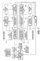
- FIG. 2 diagrammatically illustrates a portion of the document processing system
- FIG. 3 is a flow chart of a portion of a control methodology for adjusting print uniformity in the document processing system
- FIG. 4 is a flow chart of a detailed portion of a control methodology for adjusting print uniformity of the document processing system
- FIG. 5 diagrammatically illustrates a detailed portion of the document processing system
- FIG. 6 is a flow chart of a portion of a detailed control methodology for adjusting print uniformity in the document processing system
- FIG. 7 diagrammatically illustrates a portion of the document processing system
- FIG. 8 is a flow chart of a portion of a control methodology for adjusting print uniformity in the document processing system.
- an example printing or document processing system 6 includes first, second, . . . , nth marking engine processing units 8 1 , 8 2 , 8 3 , . . . , 8 n each including an associated first, second, . . . , nth marking or print engines or devices 10 , 12 , 14 and associated entry and exit inverter/bypasses 16 , 18 .
- marking engines are removable.
- an integrated marking engine and entry and exit inverter/bypasses of the processing unit 8 4 are shown as removed, leaving only a forward or upper paper path 20 .
- the functional marking engine portion can be removed for repair, or can be replaced to effectuate an upgrade or modification of the printing system 6 .
- three marking engines 10 , 12 , 14 are illustrated (with the fourth marking engine being removed), the number of marking engines can be one, two, three, four, five, or more.
- Providing at least two marking engines typically provides enhanced features and capabilities for the printing system 6 since marking tasks can be distributed amongst the at least two marking engines.
- Some or all of the marking engines 10 , 12 , 14 may be identical to provide redundancy or improved productivity through parallel printing. Alternatively or additionally, some or all of the marking engines 10 , 12 , 14 may be different to provide different capabilities.
- the marking engines 12 , 14 may be color marking engines, while the marking engine 10 may be a black (K) marking engine.
- a digital image generating mechanism or device or algorithm 22 generates a digital image to be printed by the marking engines 10 , 12 , 14 .
- an analyzer 24 matches measured print densities or relative reflectance values between the marking engines to avoid noticeable image differences within a print job by adjusting at least one of binary values of the digital image and xerography.
- a processing unit 26 1 , 26 2 , . . . , 26 n of each associated marking engine 10 , 12 , 14 adjusts the digital image and/or xerography locally, at each marking engine 10 , 12 , 14 before printing.
- the digital image and/or xerography are adjusted globally, before the digital image is sent to the marking engines 10 , 12 , 14 for imaging.
- any combination of the above examples can be employed.
- the illustrated marking engines 10 , 12 , 14 employ xerographic printing technology, in which an electrostatic image is formed and coated with a toner material, and then transferred and fused to paper or another print medium by application of heat and pressure.
- marking engines employing other printing technologies can be provided, such as marking engines employing ink jet transfer, thermal impact printing, or so forth.
- the processing units of the printing system 6 can also be other than marking engines; such as, for example, a print media feeding source or feeder 30 which includes associated print media conveying components 32 .
- the media feeding source 30 supplies paper or other print media for printing.
- Another example of the processing unit is a finisher 34 which includes associated print media conveying components 36 .
- the finisher 34 provides finishing capabilities such as collation, stapling, folding, stacking, hole-punching, binding, postage stamping, and so forth.
- the print media is printed by an imaging component 38 of each associated engine and fused by an associated fuser 39 .
- the print media feeding source 30 includes print media sources or input trays 40 , 42 , 44 , 46 connected with the print media conveying components 32 to provide selected types of print media. While four print media sources are illustrated, the number of print media sources can be one, two, three, four, five, or more. Moreover, while the illustrated print media sources 40 , 42 , 44 , 46 are embodied as components of the dedicated print media feeding source 30 , in other embodiments one or more of the marking engine processing units may include its own dedicated print media source instead of or in addition to those of the print media feeding source 30 . Each of the print media sources 40 , 42 , 44 , 46 can store sheets of the same type of print media, or can store different types of print media.
- the print media sources 42 , 44 may store the same type of large-size paper sheets
- print media source 40 may store company letterhead paper
- the print media source 46 may store letter-size paper.
- the print media can be substantially any type of media upon which one or more of the marking engines 10 , 12 , 14 can print, such as high quality bond paper, lower quality “copy” paper, overhead transparency sheets, high gloss paper, and so forth.
- the finisher 34 includes two or more print media finishing destinations or stackers 50 , 52 , 54 for collecting sequential pages of each print job that is being contemporaneously printed by the printing system 6 .
- the number of the print jobs that the printing system 6 can contemporaneously process is limited to the number of available stackers. While three finishing destinations are illustrated, the printing system 6 may include two, three, four, or more print media finishing destinations.
- the finisher 34 deposits each sheet after processing in one of the print media finishing destinations 50 , 52 , 54 , which may be trays, pans, stackers and so forth. While only one finishing processing unit is illustrated, it is contemplated that two, three, four or more finishing processing units can be employed in the printing system 6 .
- Bypass routes 20 , 60 in each marking engine processing unit provide a means by which the sheets can pass through the corresponding marking engine processing unit without interacting with the marking engine.
- Branch paths 62 , 64 are also provided to take the sheet into the associated marking engine and to deliver the sheet back to the upper or forward paper path 20 of the associated marking engine processing unit.
- the printing system 6 executes print jobs.
- Print job execution involves printing selected text, line graphics, images, machine ink character recognition (MICR) notation, or so forth on front, back, or front and back sides or pages of one or more sheets of paper or other print media.
- MICR machine ink character recognition
- some sheets may be left completely blank.
- some sheets may have mixed color and black-and-white printing.
- Execution of the print job may also involve collating the sheets in a certain order.
- the print job may include folding, stapling, punching holes into, or otherwise physically manipulating or binding the sheets.
- Print jobs can be supplied to the printing system 6 in various ways.
- a built-in optical scanner 70 can be used to scan a document such as book pages, a stack of printed pages, or so forth, to create a digital image of the scanned document that is reproduced by printing operations performed by the printing system 6 .
- one or more print jobs 72 can be electronically delivered to a system controller 74 of the printing system 6 via a wired connection 76 from a digital network 80 that interconnects example computers 82 , 84 or other digital devices.
- a network user operating word processing software running on the computer 84 may select to print the word processing document on the printing system 6 , thus generating the print job 72
- an external scanner (not shown) connected to the network 80 may provide the print job in electronic form.
- the digital network 80 can be a local area network such as a wired Ethernet, a wireless local area network (WLAN), the Internet, some combination thereof, or so forth.
- WLAN wireless local area network
- the printing system 6 is an illustrative example. In general, any number of print media sources, media handlers, marking engines, collators, finishers or other processing units can be connected together by a suitable print media conveyor configuration. While the printing system 6 illustrates a 2 ⁇ 2 configuration of four marking engines, buttressed by the print media feeding source on one end and by the finisher on the other end, other physical layouts can be used, such as an entirely horizontal arrangement, stacking of processing units three or more units high, or so forth. Moreover, while in the printing system 6 the processing units have removable functional portions, in some other embodiments some or all processing units may have non-removable functional portions.
- marking engine portion of the marking engine processing unit is non-removable, associated upper or forward paper paths 20 through each marking engine processing unit enables the marking engines to be taken “off-line” for repair or modification while the remaining processing units of the printing system continue to function as usual.
- bypass path of the conveyor in such configurations suitably passes through the functional portion of a processing unit, and optional bypassing of the processing unit is effectuated by conveying the sheet through the functional portion without performing any processing operations.
- the printing system may be a stand alone printer or a cluster of networked or otherwise logically interconnected printers, with each printer having its own associated print media source and finishing components including a plurality of final media destinations.
- path elements which might include, for example, inverters, reverters, interposers, and the like, as known in the art to direct the print media between the feeders, printing or marking engines and/or finishers.
- the controller 74 controls the production of printed sheets, the transportation over the media path, and the collation and assembly as job output by the finisher.
- the digital image generating mechanism or algorithm or device 22 generates 92 a digital image D to be printed by the first and second marking or print engines 10 , 12 .
- the digital image is received 94 , 96 by corresponding first or second print engines 10 , 12 and imaged or printed 98 , 100 by first and second printer or engine imaging devices 102 , 104 .
- respective first and second engine patches 106 , 108 are printed or imaged.
- print density of the first and second engine patches 106 , 108 is measured 110 , 112 by respective first and second engine response or patch sensors 114 , 116 .
- the measurements are analyzed 118 by the analyzer 24 to determine whether adjustment of at least one of the first and second print engine 10 , 12 is required. More specifically, the analyzer 24 determines whether only lightening or contrast of one of the print engines needs to be adjusted, or both lightening and contrast of at least one print engine 10 , 12 needs to be adjusted.
- first and second engine xerographic adjusting device, mechanism, or algorithm 120 , 122 adjusts 124 , 126 xerography of an associated first or second print engine 10 , 12 to adjust lightness of a tone reproduction curve of the associated print engine 10 , 12 .
- First and second local image adjusting devices 128 , 130 adjust 132 , 134 the digital image of the corresponding first or second print engine 10 , 12 to adjust contrast of the image as, for example, described in U.S. Patent Application Publication No. 2003/0090729, identified above.
- a control methodology approach 136 controls print consistency in the printing system 6 that includes the first and second marking or print engines 10 , 12 so that the output image of the first marking engine 10 substantially matches the output image of the second marking engine 12 .
- density or reflectance targets 138 , 140 for corresponding first and second marking engines 10 , 12 for each desired area coverage are determined, for example, in advance.
- the first and second response or patch sensors 114 , 116 of the first and second marking engines 10 , 12 acquire voltage measurements, such as black tone area coverage (BTAC) voltage measurements, from several halftone patches.
- BTAC black tone area coverage
- a stray light voltage value V off of each of the first and second marking engines 10 , 12 is measured 142 , 144 .
- the stray voltage V off is the voltage when the lamp is OFF.
- a bare photoreceptor voltage V bare of each of the first and second marking engines 10 , 12 is measured 146 , 148 .
- the digital image generating mechanism 22 generates the image data to be imaged by the first and second marking engine imaging devices 102 , 104 of the associated first and second marking engines 10 , 12 , e.g. the digital image generating mechanism 22 generates the image data for the first and second patches 106 , 108 for each selected area coverage.
- the image data is generated for three patches, each patch corresponding to the low area coverage such as 12.5% area coverage, mid area coverage such as 50% or 60% area coverage and high area coverage such as 75% or 87.5% area coverage.
- the generated image data or first and second patches 106 , 108 are imaged or printed 98 , 100 by the respective first and second print engines 10 , 12 in an interdocument zone, e.g. in the zone in which the ink is not transferred to the print media.
- the number of patches printed and corresponding targets may be other than three, such as one, two, four, five, etc.
- first and second patch sensors 114 , 116 measure voltage values 158 , 160 for each patch printed with the corresponding first or second marking engines 10 , 12 .
- first and second filters 162 , 164 filter 166 , 168 the measured voltage values or measurements.
- the first and second filters 162 , 164 average the measured voltage values, reject too low or too high values, and the like.
- An image quality controller or control algorithm or device 200 compares 202 the determined engine to engine error RR_ERR(AC) AB with a first predetermined threshold T H1 . If the determined engine to engine error RR_ERR(AC) AB is less than or equal to the first predetermined threshold T H1 , the normal quality control operation of the document processing system 6 continues, e.g. the control patches are printed and checked as described above. If the determined engine to engine error RR_ERR(AC) AB is greater than the first predetermined threshold T H1 , the image quality controller 200 selects an adjustment method and adjusts 204 at least one of the marking engines 10 , 12 .
- a decomposing algorithm or device or processor 210 decomposes 212 the determined engine to engine error values to extract lightening and residual components 214 .
- the image quality controller 200 determines 216 whether the residual component is present. If no residual component is present, at least one of the first and second engine xerographic adjusting device 120 , 122 adjusts lightness 220 of one of the first and second marking engines 10 , 12 as described below. If the residual component is present, the image quality controller 200 compares 222 the residual component to a second predetermined threshold T H2 .
- At least one of the first and second local image adjusting device 128 , 130 adjusts contrast 224 of at least one of the first and second marking engine 10 , 12 as described, for example, in U.S. Patent Application Publication No. 2003/0090729, identified above. If the residual component is less than or equal to the second threshold T H2 , both lightness and contrast are adjusted 226 of at least one of the first and second marking engines 10 , 12 in accordance with the values of the lightening and residual components by the first and second printer xerographic adjusting devices 120 , 122 and first and second local image adjusting devices 128 , 130 .
- the lightness of the second marking engine 12 is adjusted based on the first engine error RR_ERR (AC) Engine — A .
- the first marking engine 10 remains the same, while the second marking engine 12 tracks the print density of the first marking engine 10 .
- a filter filters the determined relative reflectance error values RR_ERR(AC) Engine — A for each patch printed with the first marking engine 10 .
- the filter averages the error values, rejects too low or too high values, and the like.
- the modified second engine target 230 is determined based on the averaged relative reflectance error values of the first marking engine 10 .
- the determined modified relative reflectance error of the second marking engine 12 is compared 238 to predetermined tolerances of the second marking engine 12 . If the modified relative reflectance error of the second marking engine 12 is outside of tolerances, the document processing system 6 is errored out. If the modified relative reflectance error is within the tolerances, corresponding actuators 240 of at least one of the first and second marking engine 10 , 12 as known in the art are adjusted 242 to improve image quality in the print job production so that the density of portions of the print job printed with the second marking engine 12 substantially matches the density of portions of the print job printed with the first marking engine 10 .
- the determined engine to engine error value RR_ERR(AC) AB of each patch is compared to a precalculated goal.
- a minimum stability acceptance curve is derived from the studies as 95% of an acceptance curve.
- the goal curve is derived, for example, as 50% of the minimum acceptance curve.
- the one of the first and second engine xerographic adjusting device 120 , 122 selects one of the control strategies or algorithms such as, for example, one or more targets are adjusted in the manner described above, one or more printing system actuators 240 are adjusted or the printing system 6 is reset.
- the lightness of the marking engines can be adjusted by adjusting each single engine's lightness in accordance with predetermined tolerances.
- the digital image generating mechanism 22 generates 92 digital images D 1 , D 2 for the first and second print engines 10 , 12 .
- a digital image global adjusting device 28 adjusts 252 contrast for the digital image data as determined by the image quality control device 200 before the adjusted digital images D 1 ′, D 2 ′ are received 254 , 256 by the first and second marking engines 10 , 12 .
- the globally adjusted digital images D 1 ′, D 2 ′ are adjusted by at least one of the local image adjusting device 128 , 130 at the associated marking engine 10 , 12 .
- the algorithms for adjusting contrast, e.g. binary values, of the digital images are known in the art, such as, for example, the algorithms described in U.S. Patent Application Publication No. 2003/0090729, identified above.
- the printing system 6 is adjusted in a real time to compensate for differences in lightness and contrast so that the density of portions of the print job printed with the first marking engine 10 substantially matches the density of portions of the print job printed with the second engine 12 .
- the more substantial adjustments are made by a use of xerography.
- the additional, only as needed, adjustments are done to the binary image.
- the artifacts, that typically are caused by adjustments to the digital image are minimized, particularly in such complex areas as tinted embedded text.
- each image element is tagged and individually adjusted.
- Tags identify, for example, each image element as fine, line, pictorial, text, and the like.
Abstract
Description
RR(AC)Engine
RR(AC)Engine
- where RR(AC)Engine
— A is the relative reflectance of each patch printed with the first marking engine; - RR(AC)Engine
— B is the relative reflectance of each patch printed with the second marking engine; - V(AC)A, V(AC)B is the voltage measurement values for each patch printed with the respective first and second marking engines;
- Voff
— A, Voff— B is the stray light effect on sensor or stray voltage value of the respective first and second marking engines; and - Vbare
— A, Vbare— B is the bare photoreceptor voltage values of the respective first and second marking engines.
RR — ERR(AC)Engine
RR — ERR(AC)Engine
- where RR_ERR(AC)Engine
— A, RR_ERR(AC)Engine— B is the value of a relative reflectance the error of a patch printed with the first and second marking engines; - RR(AC)Engine
— A, RR(AC)Engine— B is the relative reflectance value of a patch printed with the first and second marking engines; and - RR(AC)Target
— A, RR(AC)— A is the reflectance value of the target for a corresponding patch for the first and second marking engines.
RR — ERR(AC)AB =RR — ERR(AC)Engine
- where RR_ERR(AC)AB is the value of the engine to engine error;
- RR_ERR(AC)Engine
— A is the value of the error of a patch printed with the first marking engine; and - RR_ERR(AC)Engine
— B is the value of the error of a patch printed with the second marking engine.
RR′(AC)Target
where RR′(AC)Target
- RR_ERR (AC)Engine
— A is the relative reflectance error value of a patch printed with the first marking engine; and - RR(AC)Target
— B is the reflectance value of the previous second target for a corresponding patch for the second marking engine.
RR — ERR(AC)′Engine
- where RR_ERR(AC)′Engine
— B is the modified value of the relative reflectance error of a patch printed with the second marking engine; - RR(AC)Engine
— B is the relative reflectance value of a patch printed with the second marking engine; and - RR′(AC)Target
— B is the reflectance value of the adjusted second target of a given patch for the second marking engine.
Claims (19)
Priority Applications (1)
| Application Number | Priority Date | Filing Date | Title |
|---|---|---|---|
| US11/432,924 US7800777B2 (en) | 2006-05-12 | 2006-05-12 | Automatic image quality control of marking processes |
Applications Claiming Priority (1)
| Application Number | Priority Date | Filing Date | Title |
|---|---|---|---|
| US11/432,924 US7800777B2 (en) | 2006-05-12 | 2006-05-12 | Automatic image quality control of marking processes |
Publications (2)
| Publication Number | Publication Date |
|---|---|
| US20070263238A1 US20070263238A1 (en) | 2007-11-15 |
| US7800777B2 true US7800777B2 (en) | 2010-09-21 |
Family
ID=38684811
Family Applications (1)
| Application Number | Title | Priority Date | Filing Date |
|---|---|---|---|
| US11/432,924 Expired - Fee Related US7800777B2 (en) | 2006-05-12 | 2006-05-12 | Automatic image quality control of marking processes |
Country Status (1)
| Country | Link |
|---|---|
| US (1) | US7800777B2 (en) |
Families Citing this family (6)
| Publication number | Priority date | Publication date | Assignee | Title |
|---|---|---|---|---|
| US7880928B2 (en) * | 2007-12-21 | 2011-02-01 | Xerox Corporation | Color image process controls methods and systems |
| US8147026B2 (en) * | 2009-04-27 | 2012-04-03 | Eastman Kodak Company | Image quality matching in a mixed print engine assembly system |
| US20120131393A1 (en) * | 2010-11-19 | 2012-05-24 | International Business Machines Corporation | Detecting System Component Failures In A Computing System |
| US8527817B2 (en) | 2010-11-19 | 2013-09-03 | International Business Machines Corporation | Detecting system component failures in a computing system |
| US9158981B2 (en) * | 2012-03-26 | 2015-10-13 | The Procter & Gamble Company | Method and system for evaluating the quality of a rendered image |
| US9746805B2 (en) * | 2013-05-31 | 2017-08-29 | Hewlett-Packard Development Company, L.P. | Printing system |
Citations (84)
| Publication number | Priority date | Publication date | Assignee | Title |
|---|---|---|---|---|
| US4579446A (en) | 1982-07-12 | 1986-04-01 | Canon Kabushiki Kaisha | Both-side recording system |
| US4587532A (en) | 1983-05-02 | 1986-05-06 | Canon Kabushiki Kaisha | Recording apparatus producing multiple copies simultaneously |
| US4710785A (en) | 1986-12-12 | 1987-12-01 | Eastman Kodak Company | Process control for electrostatographic machine |
| US4836119A (en) | 1988-03-21 | 1989-06-06 | The Charles Stark Draper Laboratory, Inc. | Sperical ball positioning apparatus for seamed limp material article assembly system |
| US5004222A (en) | 1987-05-13 | 1991-04-02 | Fuji Xerox Co., Ltd. | Apparatus for changing the direction of conveying paper |
| US5008713A (en) | 1987-08-12 | 1991-04-16 | Canon Kabushiki Kaisha | Sheet conveying apparatus and sheet conveying method |
| US5080340A (en) | 1991-01-02 | 1992-01-14 | Eastman Kodak Company | Modular finisher for a reproduction apparatus |
| US5095342A (en) | 1990-09-28 | 1992-03-10 | Xerox Corporation | Methods for sheet scheduling in an imaging system having an endless duplex paper path loop |
| US5159395A (en) | 1991-08-29 | 1992-10-27 | Xerox Corporation | Method of scheduling copy sheets in a dual mode duplex printing system |
| US5208640A (en) | 1989-11-09 | 1993-05-04 | Fuji Xerox Co., Ltd. | Image recording apparatus |
| US5272511A (en) | 1992-04-30 | 1993-12-21 | Xerox Corporation | Sheet inserter and methods of inserting sheets into a continuous stream of sheets |
| US5326093A (en) | 1993-05-24 | 1994-07-05 | Xerox Corporation | Universal interface module interconnecting various copiers and printers with various sheet output processors |
| US5436705A (en) * | 1994-04-18 | 1995-07-25 | Xerox Corporation | Adaptive process controller for electrophotographic printing |
| US5435544A (en) | 1993-04-27 | 1995-07-25 | Xerox Corporation | Printer mailbox system signaling overdue removals of print jobs from mailbox bins |
| US5473419A (en) | 1993-11-08 | 1995-12-05 | Eastman Kodak Company | Image forming apparatus having a duplex path with an inverter |
| US5489969A (en) | 1995-03-27 | 1996-02-06 | Xerox Corporation | Apparatus and method of controlling interposition of sheet in a stream of imaged substrates |
| US5504568A (en) | 1995-04-21 | 1996-04-02 | Xerox Corporation | Print sequence scheduling system for duplex printing apparatus |
| US5510896A (en) | 1993-06-18 | 1996-04-23 | Xerox Corporation | Automatic copy quality correction and calibration |
| US5525031A (en) | 1994-02-18 | 1996-06-11 | Xerox Corporation | Automated print jobs distribution system for shared user centralized printer |
| US5557367A (en) | 1995-03-27 | 1996-09-17 | Xerox Corporation | Method and apparatus for optimizing scheduling in imaging devices |
| US5568246A (en) | 1995-09-29 | 1996-10-22 | Xerox Corporation | High productivity dual engine simplex and duplex printing system using a reversible duplex path |
| US5570172A (en) | 1995-01-18 | 1996-10-29 | Xerox Corporation | Two up high speed printing system |
| US5596416A (en) | 1994-01-13 | 1997-01-21 | T/R Systems | Multiple printer module electrophotographic printing device |
| US5629762A (en) | 1995-06-07 | 1997-05-13 | Eastman Kodak Company | Image forming apparatus having a duplex path and/or an inverter |
| US5710968A (en) | 1995-08-28 | 1998-01-20 | Xerox Corporation | Bypass transport loop sheet insertion system |
| US5778377A (en) | 1994-11-04 | 1998-07-07 | International Business Machines Corporation | Table driven graphical user interface |
| US5884118A (en) | 1996-11-26 | 1999-03-16 | Xerox Corporation | Printer having print output linked to scanner input for automated image quality adjustment |
| US5884910A (en) | 1997-08-18 | 1999-03-23 | Xerox Corporation | Evenly retractable and self-leveling nips sheets ejection system |
| US5933680A (en) * | 1996-02-29 | 1999-08-03 | Canon Kabushiki Kaisha | Image processing apparatus and method for optimizing an image formation condition |
| US5995721A (en) | 1996-10-18 | 1999-11-30 | Xerox Corporation | Distributed printing system |
| US6035103A (en) * | 1995-08-07 | 2000-03-07 | T/R Systems | Color correction for multiple print engine system with half tone and bi-level printing |
| US6035152A (en) * | 1997-04-11 | 2000-03-07 | Xerox Corporation | Method for measurement of tone reproduction curve |
| US6046820A (en) * | 1996-10-22 | 2000-04-04 | Canon Kabushiki Kaisha | Image forming device and computer which share the generation of a function for correcting image data based on an image forming condition of the image forming device |
| US6059284A (en) | 1997-01-21 | 2000-05-09 | Xerox Corporation | Process, lateral and skew sheet positioning apparatus and method |
| US6125248A (en) | 1998-11-30 | 2000-09-26 | Xerox Corporation | Electrostatographic reproduction machine including a plurality of selectable fusing assemblies |
| US6147698A (en) * | 1997-05-29 | 2000-11-14 | International Business Machines Corporation | Density control for a printer |
| US6241242B1 (en) | 1999-10-12 | 2001-06-05 | Hewlett-Packard Company | Deskew of print media |
| US6297886B1 (en) | 1996-06-05 | 2001-10-02 | John S. Cornell | Tandem printer printing apparatus |
| US6337958B1 (en) * | 2000-09-05 | 2002-01-08 | International Business Machines Corporation | Matching the printing characteristics between two engines of a duplex print system |
| US6341773B1 (en) | 1999-06-08 | 2002-01-29 | Tecnau S.R.L. | Dynamic sequencer for sheets of printed paper |
| US6384918B1 (en) | 1999-11-24 | 2002-05-07 | Xerox Corporation | Spectrophotometer for color printer color control with displacement insensitive optics |
| US6404511B1 (en) * | 1998-12-11 | 2002-06-11 | Seiko Epson Corporation | Self-calibration of network copier system |
| US20020078012A1 (en) | 2000-05-16 | 2002-06-20 | Xerox Corporation | Database method and structure for a finishing system |
| US6418281B1 (en) | 1999-02-24 | 2002-07-09 | Canon Kabushiki Kaisha | Image processing apparatus having calibration for image exposure output |
| US20020103559A1 (en) | 2001-01-29 | 2002-08-01 | Xerox Corporation | Systems and methods for optimizing a production facility |
| US6450711B1 (en) | 2000-12-05 | 2002-09-17 | Xerox Corporation | High speed printer with dual alternate sheet inverters |
| US6476923B1 (en) | 1996-06-05 | 2002-11-05 | John S. Cornell | Tandem printer printing apparatus |
| US6476376B1 (en) | 2002-01-16 | 2002-11-05 | Xerox Corporation | Two dimensional object position sensor |
| US6493098B1 (en) | 1996-06-05 | 2002-12-10 | John S. Cornell | Desk-top printer and related method for two-sided printing |
| US6537910B1 (en) | 1998-09-02 | 2003-03-25 | Micron Technology, Inc. | Forming metal silicide resistant to subsequent thermal processing |
| US6550762B2 (en) | 2000-12-05 | 2003-04-22 | Xerox Corporation | High speed printer with dual alternate sheet inverters |
| US20030077095A1 (en) | 2001-10-18 | 2003-04-24 | Conrow Brian R. | Constant inverter speed timing strategy for duplex sheets in a tandem printer |
| US6554276B2 (en) | 2001-03-30 | 2003-04-29 | Xerox Corporation | Flexible sheet reversion using an omni-directional transport system |
| US6577925B1 (en) | 1999-11-24 | 2003-06-10 | Xerox Corporation | Apparatus and method of distributed object handling |
| US6607320B2 (en) | 2001-03-30 | 2003-08-19 | Xerox Corporation | Mobius combination of reversion and return path in a paper transport system |
| US6612571B2 (en) | 2001-12-06 | 2003-09-02 | Xerox Corporation | Sheet conveying device having multiple outputs |
| US20030164960A1 (en) * | 2001-02-22 | 2003-09-04 | Heidelberg Digital, L.L.C. | Method and system for matching marking device outputs |
| US6621576B2 (en) | 2001-05-22 | 2003-09-16 | Xerox Corporation | Color imager bar based spectrophotometer for color printer color control system |
| US6628426B2 (en) * | 2001-05-22 | 2003-09-30 | Lexmark International, Inc. | Method of halftone screen linearization via continuous gradient patches |
| US6633382B2 (en) | 2001-05-22 | 2003-10-14 | Xerox Corporation | Angular, azimuthal and displacement insensitive spectrophotometer for color printer color control systems |
| US6639669B2 (en) | 2001-09-10 | 2003-10-28 | Xerox Corporation | Diagnostics for color printer on-line spectrophotometer control system |
| US20040085561A1 (en) | 2002-10-30 | 2004-05-06 | Xerox Corporation | Planning and scheduling reconfigurable systems with regular and diagnostic jobs |
| US20040085562A1 (en) | 2002-10-30 | 2004-05-06 | Xerox Corporation. | Planning and scheduling reconfigurable systems with alternative capabilities |
| US20040088207A1 (en) | 2002-10-30 | 2004-05-06 | Xerox Corporation | Planning and scheduling reconfigurable systems around off-line resources |
| US6760553B2 (en) * | 2001-12-28 | 2004-07-06 | Hitachi Printing Solutions, Ltd. | Electrophotographic cluster printing system with controlled image quality |
| US20040153983A1 (en) | 2003-02-03 | 2004-08-05 | Mcmillan Kenneth L. | Method and system for design verification using proof-partitioning |
| US20040150158A1 (en) | 2003-02-04 | 2004-08-05 | Palo Alto Research Center Incorporated | Media path modules |
| US20040150156A1 (en) | 2003-02-04 | 2004-08-05 | Palo Alto Research Center, Incorporated. | Frameless media path modules |
| US20040196480A1 (en) * | 2003-03-31 | 2004-10-07 | Foster Thomas J. | Post rip image rendering in an electrographic printer using density patch feedback |
| US20040216002A1 (en) | 2003-04-28 | 2004-10-28 | Palo Alto Research Center, Incorporated. | Planning and scheduling for failure recovery system and method |
| US20040225394A1 (en) | 2003-04-28 | 2004-11-11 | Palo Alto Research Center, Incorporated. | Predictive and preemptive planning and scheduling for different jop priorities system and method |
| US20040225391A1 (en) | 2003-04-28 | 2004-11-11 | Palo Alto Research Center Incorporated | Monitoring and reporting incremental job status system and method |
| US6819906B1 (en) | 2003-08-29 | 2004-11-16 | Xerox Corporation | Printer output sets compiler to stacker system |
| US20040247365A1 (en) | 2003-06-06 | 2004-12-09 | Xerox Corporation | Universal flexible plural printer to plural finisher sheet integration system |
| US20050088672A1 (en) * | 2003-10-28 | 2005-04-28 | Johnson David A. | Printing system calibration |
| US6925283B1 (en) | 2004-01-21 | 2005-08-02 | Xerox Corporation | High print rate merging and finishing system for printing |
| US20060033771A1 (en) | 2004-08-13 | 2006-02-16 | Xerox Corporation. | Parallel printing architecture with containerized image marking engines |
| US20060039728A1 (en) | 2004-08-23 | 2006-02-23 | Xerox Corporation | Printing system with inverter disposed for media velocity buffering and registration |
| US7006250B2 (en) * | 2001-09-27 | 2006-02-28 | Lexmark International, Inc. | Method of setting laser power and developer bias in an electrophotographic machine based on an estimated intermediate belt reflectivity |
| US20060067756A1 (en) | 2004-09-28 | 2006-03-30 | Xerox Corporation | printing system |
| US20060066885A1 (en) | 2004-09-29 | 2006-03-30 | Xerox Corporation | Printing system |
| US20060067757A1 (en) | 2004-09-28 | 2006-03-30 | Xerox Corporation | Printing system |
| US7024152B2 (en) | 2004-08-23 | 2006-04-04 | Xerox Corporation | Printing system with horizontal highway and single pass duplex |
| US7580152B2 (en) * | 1997-11-28 | 2009-08-25 | Yoshio Kimura | Image processing apparatus and method and memory medium |
Family Cites Families (1)
| Publication number | Priority date | Publication date | Assignee | Title |
|---|---|---|---|---|
| US5844118A (en) * | 1997-01-31 | 1998-12-01 | Pioneer Hi-Bred International, Inc. | Hybrid maize plant and seed (32K61) |
-
2006
- 2006-05-12 US US11/432,924 patent/US7800777B2/en not_active Expired - Fee Related
Patent Citations (88)
| Publication number | Priority date | Publication date | Assignee | Title |
|---|---|---|---|---|
| US4579446A (en) | 1982-07-12 | 1986-04-01 | Canon Kabushiki Kaisha | Both-side recording system |
| US4587532A (en) | 1983-05-02 | 1986-05-06 | Canon Kabushiki Kaisha | Recording apparatus producing multiple copies simultaneously |
| US4710785A (en) | 1986-12-12 | 1987-12-01 | Eastman Kodak Company | Process control for electrostatographic machine |
| US5004222A (en) | 1987-05-13 | 1991-04-02 | Fuji Xerox Co., Ltd. | Apparatus for changing the direction of conveying paper |
| US5008713A (en) | 1987-08-12 | 1991-04-16 | Canon Kabushiki Kaisha | Sheet conveying apparatus and sheet conveying method |
| US4836119A (en) | 1988-03-21 | 1989-06-06 | The Charles Stark Draper Laboratory, Inc. | Sperical ball positioning apparatus for seamed limp material article assembly system |
| US5208640A (en) | 1989-11-09 | 1993-05-04 | Fuji Xerox Co., Ltd. | Image recording apparatus |
| US5095342A (en) | 1990-09-28 | 1992-03-10 | Xerox Corporation | Methods for sheet scheduling in an imaging system having an endless duplex paper path loop |
| US5080340A (en) | 1991-01-02 | 1992-01-14 | Eastman Kodak Company | Modular finisher for a reproduction apparatus |
| US5159395A (en) | 1991-08-29 | 1992-10-27 | Xerox Corporation | Method of scheduling copy sheets in a dual mode duplex printing system |
| US5272511A (en) | 1992-04-30 | 1993-12-21 | Xerox Corporation | Sheet inserter and methods of inserting sheets into a continuous stream of sheets |
| US5435544A (en) | 1993-04-27 | 1995-07-25 | Xerox Corporation | Printer mailbox system signaling overdue removals of print jobs from mailbox bins |
| US5326093A (en) | 1993-05-24 | 1994-07-05 | Xerox Corporation | Universal interface module interconnecting various copiers and printers with various sheet output processors |
| US5510896A (en) | 1993-06-18 | 1996-04-23 | Xerox Corporation | Automatic copy quality correction and calibration |
| US5473419A (en) | 1993-11-08 | 1995-12-05 | Eastman Kodak Company | Image forming apparatus having a duplex path with an inverter |
| US5596416A (en) | 1994-01-13 | 1997-01-21 | T/R Systems | Multiple printer module electrophotographic printing device |
| US5525031A (en) | 1994-02-18 | 1996-06-11 | Xerox Corporation | Automated print jobs distribution system for shared user centralized printer |
| US5436705A (en) * | 1994-04-18 | 1995-07-25 | Xerox Corporation | Adaptive process controller for electrophotographic printing |
| US5778377A (en) | 1994-11-04 | 1998-07-07 | International Business Machines Corporation | Table driven graphical user interface |
| US5570172A (en) | 1995-01-18 | 1996-10-29 | Xerox Corporation | Two up high speed printing system |
| US5557367A (en) | 1995-03-27 | 1996-09-17 | Xerox Corporation | Method and apparatus for optimizing scheduling in imaging devices |
| US5489969A (en) | 1995-03-27 | 1996-02-06 | Xerox Corporation | Apparatus and method of controlling interposition of sheet in a stream of imaged substrates |
| US5504568A (en) | 1995-04-21 | 1996-04-02 | Xerox Corporation | Print sequence scheduling system for duplex printing apparatus |
| US5629762A (en) | 1995-06-07 | 1997-05-13 | Eastman Kodak Company | Image forming apparatus having a duplex path and/or an inverter |
| US6035103A (en) * | 1995-08-07 | 2000-03-07 | T/R Systems | Color correction for multiple print engine system with half tone and bi-level printing |
| US5710968A (en) | 1995-08-28 | 1998-01-20 | Xerox Corporation | Bypass transport loop sheet insertion system |
| US5568246A (en) | 1995-09-29 | 1996-10-22 | Xerox Corporation | High productivity dual engine simplex and duplex printing system using a reversible duplex path |
| US5933680A (en) * | 1996-02-29 | 1999-08-03 | Canon Kabushiki Kaisha | Image processing apparatus and method for optimizing an image formation condition |
| US6493098B1 (en) | 1996-06-05 | 2002-12-10 | John S. Cornell | Desk-top printer and related method for two-sided printing |
| US6476923B1 (en) | 1996-06-05 | 2002-11-05 | John S. Cornell | Tandem printer printing apparatus |
| US6297886B1 (en) | 1996-06-05 | 2001-10-02 | John S. Cornell | Tandem printer printing apparatus |
| US5995721A (en) | 1996-10-18 | 1999-11-30 | Xerox Corporation | Distributed printing system |
| US6046820A (en) * | 1996-10-22 | 2000-04-04 | Canon Kabushiki Kaisha | Image forming device and computer which share the generation of a function for correcting image data based on an image forming condition of the image forming device |
| US5884118A (en) | 1996-11-26 | 1999-03-16 | Xerox Corporation | Printer having print output linked to scanner input for automated image quality adjustment |
| US6059284A (en) | 1997-01-21 | 2000-05-09 | Xerox Corporation | Process, lateral and skew sheet positioning apparatus and method |
| US6035152A (en) * | 1997-04-11 | 2000-03-07 | Xerox Corporation | Method for measurement of tone reproduction curve |
| US6147698A (en) * | 1997-05-29 | 2000-11-14 | International Business Machines Corporation | Density control for a printer |
| US5884910A (en) | 1997-08-18 | 1999-03-23 | Xerox Corporation | Evenly retractable and self-leveling nips sheets ejection system |
| US7580152B2 (en) * | 1997-11-28 | 2009-08-25 | Yoshio Kimura | Image processing apparatus and method and memory medium |
| US6537910B1 (en) | 1998-09-02 | 2003-03-25 | Micron Technology, Inc. | Forming metal silicide resistant to subsequent thermal processing |
| US6125248A (en) | 1998-11-30 | 2000-09-26 | Xerox Corporation | Electrostatographic reproduction machine including a plurality of selectable fusing assemblies |
| US6404511B1 (en) * | 1998-12-11 | 2002-06-11 | Seiko Epson Corporation | Self-calibration of network copier system |
| US6418281B1 (en) | 1999-02-24 | 2002-07-09 | Canon Kabushiki Kaisha | Image processing apparatus having calibration for image exposure output |
| US6341773B1 (en) | 1999-06-08 | 2002-01-29 | Tecnau S.R.L. | Dynamic sequencer for sheets of printed paper |
| US6241242B1 (en) | 1999-10-12 | 2001-06-05 | Hewlett-Packard Company | Deskew of print media |
| US6384918B1 (en) | 1999-11-24 | 2002-05-07 | Xerox Corporation | Spectrophotometer for color printer color control with displacement insensitive optics |
| US6577925B1 (en) | 1999-11-24 | 2003-06-10 | Xerox Corporation | Apparatus and method of distributed object handling |
| US20020078012A1 (en) | 2000-05-16 | 2002-06-20 | Xerox Corporation | Database method and structure for a finishing system |
| US6337958B1 (en) * | 2000-09-05 | 2002-01-08 | International Business Machines Corporation | Matching the printing characteristics between two engines of a duplex print system |
| US6450711B1 (en) | 2000-12-05 | 2002-09-17 | Xerox Corporation | High speed printer with dual alternate sheet inverters |
| US6550762B2 (en) | 2000-12-05 | 2003-04-22 | Xerox Corporation | High speed printer with dual alternate sheet inverters |
| US6612566B2 (en) | 2000-12-05 | 2003-09-02 | Xerox Corporation | High speed printer with dual alternate sheet inverters |
| US20020103559A1 (en) | 2001-01-29 | 2002-08-01 | Xerox Corporation | Systems and methods for optimizing a production facility |
| US20030164960A1 (en) * | 2001-02-22 | 2003-09-04 | Heidelberg Digital, L.L.C. | Method and system for matching marking device outputs |
| US6554276B2 (en) | 2001-03-30 | 2003-04-29 | Xerox Corporation | Flexible sheet reversion using an omni-directional transport system |
| US6607320B2 (en) | 2001-03-30 | 2003-08-19 | Xerox Corporation | Mobius combination of reversion and return path in a paper transport system |
| US6633382B2 (en) | 2001-05-22 | 2003-10-14 | Xerox Corporation | Angular, azimuthal and displacement insensitive spectrophotometer for color printer color control systems |
| US6621576B2 (en) | 2001-05-22 | 2003-09-16 | Xerox Corporation | Color imager bar based spectrophotometer for color printer color control system |
| US6628426B2 (en) * | 2001-05-22 | 2003-09-30 | Lexmark International, Inc. | Method of halftone screen linearization via continuous gradient patches |
| US6639669B2 (en) | 2001-09-10 | 2003-10-28 | Xerox Corporation | Diagnostics for color printer on-line spectrophotometer control system |
| US7006250B2 (en) * | 2001-09-27 | 2006-02-28 | Lexmark International, Inc. | Method of setting laser power and developer bias in an electrophotographic machine based on an estimated intermediate belt reflectivity |
| US6608988B2 (en) | 2001-10-18 | 2003-08-19 | Xerox Corporation | Constant inverter speed timing method and apparatus for duplex sheets in a tandem printer |
| US20030077095A1 (en) | 2001-10-18 | 2003-04-24 | Conrow Brian R. | Constant inverter speed timing strategy for duplex sheets in a tandem printer |
| US6612571B2 (en) | 2001-12-06 | 2003-09-02 | Xerox Corporation | Sheet conveying device having multiple outputs |
| US6760553B2 (en) * | 2001-12-28 | 2004-07-06 | Hitachi Printing Solutions, Ltd. | Electrophotographic cluster printing system with controlled image quality |
| US6476376B1 (en) | 2002-01-16 | 2002-11-05 | Xerox Corporation | Two dimensional object position sensor |
| US20040085561A1 (en) | 2002-10-30 | 2004-05-06 | Xerox Corporation | Planning and scheduling reconfigurable systems with regular and diagnostic jobs |
| US20040085562A1 (en) | 2002-10-30 | 2004-05-06 | Xerox Corporation. | Planning and scheduling reconfigurable systems with alternative capabilities |
| US20040088207A1 (en) | 2002-10-30 | 2004-05-06 | Xerox Corporation | Planning and scheduling reconfigurable systems around off-line resources |
| US20040153983A1 (en) | 2003-02-03 | 2004-08-05 | Mcmillan Kenneth L. | Method and system for design verification using proof-partitioning |
| US20040150158A1 (en) | 2003-02-04 | 2004-08-05 | Palo Alto Research Center Incorporated | Media path modules |
| US20040150156A1 (en) | 2003-02-04 | 2004-08-05 | Palo Alto Research Center, Incorporated. | Frameless media path modules |
| US20040196480A1 (en) * | 2003-03-31 | 2004-10-07 | Foster Thomas J. | Post rip image rendering in an electrographic printer using density patch feedback |
| US20040216002A1 (en) | 2003-04-28 | 2004-10-28 | Palo Alto Research Center, Incorporated. | Planning and scheduling for failure recovery system and method |
| US20040225394A1 (en) | 2003-04-28 | 2004-11-11 | Palo Alto Research Center, Incorporated. | Predictive and preemptive planning and scheduling for different jop priorities system and method |
| US20040225391A1 (en) | 2003-04-28 | 2004-11-11 | Palo Alto Research Center Incorporated | Monitoring and reporting incremental job status system and method |
| US20040247365A1 (en) | 2003-06-06 | 2004-12-09 | Xerox Corporation | Universal flexible plural printer to plural finisher sheet integration system |
| US6819906B1 (en) | 2003-08-29 | 2004-11-16 | Xerox Corporation | Printer output sets compiler to stacker system |
| US20050088672A1 (en) * | 2003-10-28 | 2005-04-28 | Johnson David A. | Printing system calibration |
| US6973286B2 (en) | 2004-01-21 | 2005-12-06 | Xerox Corporation | High print rate merging and finishing system for parallel printing |
| US6959165B2 (en) | 2004-01-21 | 2005-10-25 | Xerox Corporation | High print rate merging and finishing system for printing |
| US6925283B1 (en) | 2004-01-21 | 2005-08-02 | Xerox Corporation | High print rate merging and finishing system for printing |
| US20060033771A1 (en) | 2004-08-13 | 2006-02-16 | Xerox Corporation. | Parallel printing architecture with containerized image marking engines |
| US20060039728A1 (en) | 2004-08-23 | 2006-02-23 | Xerox Corporation | Printing system with inverter disposed for media velocity buffering and registration |
| US7024152B2 (en) | 2004-08-23 | 2006-04-04 | Xerox Corporation | Printing system with horizontal highway and single pass duplex |
| US20060067756A1 (en) | 2004-09-28 | 2006-03-30 | Xerox Corporation | printing system |
| US20060067757A1 (en) | 2004-09-28 | 2006-03-30 | Xerox Corporation | Printing system |
| US20060066885A1 (en) | 2004-09-29 | 2006-03-30 | Xerox Corporation | Printing system |
Non-Patent Citations (81)
| Title |
|---|
| Desmond Fretz, "Cluster Printing Solution Announced", Today at Xerox (TAX), No. 1129, Aug. 3, 2001. |
| Morgan, P.F., "Integration of Black Only and Color Printers", Xerox Disclosure Journal, vol. 16, No. 6, Nov./Dec. 1991, pp. 381-383. |
| U.S. Appl. No. 10/785,211, filed Feb. 24, 2004, Lofthus et al. |
| U.S. Appl. No. 10/881,619, filed Jun. 30, 2004, Bobrow. |
| U.S. Appl. No. 10/917,676, filed Aug. 13, 2004, Lofthus et al. |
| U.S. Appl. No. 10/924,458, filed Aug. 23, 2004, Lofthus et al. |
| U.S. Appl. No. 10/924,459, filed Aug. 23, 2004, Mandel et al. |
| U.S. Appl. No. 10/933,556, filed Sep. 3, 2004, Spencer et al. |
| U.S. Appl. No. 10/953,953, filed Sep. 29, 2004, Radulski et al. |
| U.S. Appl. No. 10/999,326, filed Nov. 30, 2004, Grace et al. |
| U.S. Appl. No. 10/999,450, filed Nov. 30, 2004, Lofthus et al. |
| U.S. Appl. No. 11/000,158, filed Nov. 30, 2004, Roof. |
| U.S. Appl. No. 11/000,168, filed Nov. 30, 2004, Biegelsen et al. |
| U.S. Appl. No. 11/000,258, filed Nov. 30, 2004, Roof. |
| U.S. Appl. No. 11/051,817, filed Feb. 4, 2005, Moore et al. |
| U.S. Appl. No. 11/069,020, filed Feb. 28, 2005, Lofthus et al. |
| U.S. Appl. No. 11/070,681, filed Mar. 2, 2005, Viturro et al. |
| U.S. Appl. No. 11/081,473, filed Mar. 16, 2005, Moore. |
| U.S. Appl. No. 11/084,280, filed Mar. 18, 2005, Mizes. |
| U.S. Appl. No. 11/089,854, filed Mar. 25, 2005, Clark et al. |
| U.S. Appl. No. 11/090,498, filed Mar. 25, 2005, Clark. |
| U.S. Appl. No. 11/090,502, filed Mar. 25, 2005, Mongeon. |
| U.S. Appl. No. 11/093,229, filed Mar. 29, 2005, Julien. |
| U.S. Appl. No. 11/094,864, filed Mar. 31, 2005, de Jong et al. |
| U.S. Appl. No. 11/094,998, filed Mar. 31, 2005, Moore et al. |
| U.S. Appl. No. 11/095,378, filed Mar. 31, 2005, Moore et al. |
| U.S. Appl. No. 11/095,872, filed Mar. 31, 2005, Julien et al. |
| U.S. Appl. No. 11/102,332, filed Apr. 8, 2005, Hindi et al. |
| U.S. Appl. No. 11/102,355, filed Apr. 8, 2005, Fromherz et al. |
| U.S. Appl. No. 11/102,899, filed Apr. 8, 2005, Crawford et al. |
| U.S. Appl. No. 11/102,910, filed Apr. 8, 2005, Crawford et al. |
| U.S. Appl. No. 11/109,558, filed Apr. 19, 2005, Furst et al. |
| U.S. Appl. No. 11/109,566, filed Apr. 19, 2005, Mandel et al. |
| U.S. Appl. No. 11/109,996, filed Apr. 20, 2005, Mongeon et al. |
| U.S. Appl. No. 11/115,766, filed Apr. 27, 2005, Grace. |
| U.S. Appl. No. 11/122,420, filed May 5, 2005, Richards. |
| U.S. Appl. No. 11/136,959, filed May 25, 2005, German et al. |
| U.S. Appl. No. 11/137,251, filed May 25, 2005, Lofthus et al. |
| U.S. Appl. No. 11/137,634, filed May 25, 2005. Lofthus et al. |
| U.S. Appl. No. 11/143,818, filed Jun. 2, 2005, Dalal et al. |
| U.S. Appl. No. 11/146,665, filed Jun. 7, 2005, Mongeon. |
| U.S. Appl. No. 11/152,275, filed Jun. 14, 2005, Roof et al. |
| U.S. Appl. No. 11/156,778, filed Jun. 20, 2005, Swift. |
| U.S. Appl. No. 11/157,598. filed Jun. 21, 2005, Frankel. |
| U.S. Appl. No. 11/166,299, filed Jun. 24, 2005, Moore. |
| U.S. Appl. No. 11/166,460, filed Jun. 24, 2005, Roof et al. |
| U.S. Appl. No. 11/166,581, filed Jun. 24, 2005, Lang et al. |
| U.S. Appl. No. 11/170,845, filed Jun. 30, 2005, Sampath et al. |
| U.S. Appl. No. 11/170,873, filed Jun. 30, 2005, Klassen. |
| U.S. Appl. No. 11/170,975, filed Jun. 30, 2005, Klassen. |
| U.S. Appl. No. 11/189,371, filed Jul. 26, 2005, Moore et al. |
| U.S. Appl. No. 11/208,871, filed Aug. 22, 2005, Dalal et al. |
| U.S. Appl. No. 11/212,367, filed Aug. 26, 2005, Anderson et al. |
| U.S. Appl. No. 11/215,791, filed Aug. 30, 2005, Hamby et al. |
| U.S. Appl. No. 11/222,260, filed Sep. 8, 2005, Goodman et al. |
| U.S. Appl. No. 11/234,468, filed Sep. 23, 2005, Hamby et al. |
| U.S. Appl. No. 11/234,553, filed Sep. 23, 2005, Mongeon. |
| U.S. Appl. No. 11/247,778, filed Oct. 11, 2005, Radulski et al. |
| U.S. Appl. No. 11/248,044, filed Oct. 12, 2005, Spencer et al. |
| U.S. Appl. No. 11/274,638, filed Nov. 15, 2005, Wu et al. |
| U.S. Appl. No. 11/287,177, filed Nov. 23, 2005, Mandel et al. |
| U.S. Appl. No. 11/287,685, filed Nov. 28, 2005, Carolan. |
| U.S. Appl. No. 11/291,583, filed Nov. 30, 2005, Lang. |
| U.S. Appl. No. 11/291,860, filed Nov. 30, 2005, Willis. |
| U.S. Appl. No. 11/292,163, filed Nov. 30, 2005, Mandel et al. |
| U.S. Appl. No. 11/292,388, filed Nov. 30, 2005, Mueller. |
| U.S. Appl. No. 11/312,081, filed Dec. 20, 2005, Mandel et al. |
| U.S. Appl. No. 11/314,774, filed Dec. 21, 2005, Klassen. |
| U.S. Appl. No. 11/314,828, filed Dec. 21, 2005, Anderson et al. |
| U.S. Appl. No. 11/317,167, filed Dec. 23, 2005, Lofthus et al. |
| U.S. Appl. No. 11/317,589, filed Dec. 23, 2005, Biegelsen et al. |
| U.S. Appl. No. 11/331,627, filed Jan. 13, 2006, Moore. |
| U.S. Appl. No. 11/341,733, filed Jan. 27, 2006, German. |
| U.S. Appl. No. 11/349,828, filed Feb. 8, 2006, Banton. |
| U.S. Appl. No. 11/359,065, filed Feb. 22, 2005, Banton. |
| U.S. Appl. No. 11/363,378, filed Feb. 27, 2006, Anderson et al. |
| U.S. Appl. No. 11/364,685, filed Feb. 28, 2006, Hindi et al. |
| U.S. Appl. No. 11/378,040, filed Mar. 17, 2006, German. |
| U.S. Appl. No. 11/378,046, filed Mar. 17, 2006, Rizzolo et al. |
| U.S. Appl. No. 11/399,100, filed Apr. 6, 2006, Paul. |
| U.S. Appl. No. 11/403,785, filed Apr. 13, 2006, Banton et al. |
Also Published As
| Publication number | Publication date |
|---|---|
| US20070263238A1 (en) | 2007-11-15 |
Similar Documents
| Publication | Publication Date | Title |
|---|---|---|
| US7911652B2 (en) | Methods and systems for determining banding compensation parameters in printing systems | |
| US7697151B2 (en) | Image quality control method and apparatus for multiple marking engine systems | |
| US7593130B2 (en) | Printing systems | |
| US7965397B2 (en) | Systems and methods to measure banding print defects | |
| US7162172B2 (en) | Semi-automatic image quality adjustment for multiple marking engine systems | |
| EP1626312B1 (en) | Multiple object sources controlled and/or selected based on a common sensor | |
| US7382993B2 (en) | Process controls methods and apparatuses for improved image consistency | |
| US20060244980A1 (en) | Image quality adjustment method and system | |
| US7203434B2 (en) | Color image forming apparatus and method of controlling same | |
| US8169657B2 (en) | Registration method using sensed image marks and digital realignment | |
| US8451519B2 (en) | Method and apparatus for controlling color in multicolor marking platform | |
| US7800777B2 (en) | Automatic image quality control of marking processes | |
| US9774763B2 (en) | Method for controlling a printing process | |
| JP2021044697A (en) | Image forming apparatus | |
| US7495799B2 (en) | Maximum gamut strategy for the printing systems | |
| US20220383056A1 (en) | Image forming apparatus | |
| US7880928B2 (en) | Color image process controls methods and systems | |
| US7872776B2 (en) | Methods, systems and apparatus to control hue variation for multiple marking engine printing systems | |
| JP2019101074A (en) | Image formation apparatus and program | |
| US10656583B2 (en) | Image forming system | |
| US11796949B2 (en) | Image forming apparatus | |
| JP2022075726A (en) | Image inspection device, image inspection system, image inspection method, and image inspection program | |
| JP2020175627A (en) | Image formation device, and control method thereof | |
| JP2005209037A (en) | Print inspection device |
Legal Events
| Date | Code | Title | Description |
|---|---|---|---|
| AS | Assignment |
Owner name: XEROX CORPORATION, CONNECTICUT Free format text: ASSIGNMENT OF ASSIGNORS INTEREST;ASSIGNORS:LIEBERMAN, DAVID J.;BLITZ, WILLIAM A.;MONGEON, MICHAEL C.;AND OTHERS;REEL/FRAME:017898/0347;SIGNING DATES FROM 20060501 TO 20060502 Owner name: XEROX CORPORATION, CONNECTICUT Free format text: ASSIGNMENT OF ASSIGNORS INTEREST;ASSIGNORS:LIEBERMAN, DAVID J.;BLITZ, WILLIAM A.;MONGEON, MICHAEL C.;AND OTHERS;SIGNING DATES FROM 20060501 TO 20060502;REEL/FRAME:017898/0347 |
|
| FEPP | Fee payment procedure |
Free format text: PAYOR NUMBER ASSIGNED (ORIGINAL EVENT CODE: ASPN); ENTITY STATUS OF PATENT OWNER: LARGE ENTITY |
|
| STCF | Information on status: patent grant |
Free format text: PATENTED CASE |
|
| FPAY | Fee payment |
Year of fee payment: 4 |
|
| MAFP | Maintenance fee payment |
Free format text: PAYMENT OF MAINTENANCE FEE, 8TH YEAR, LARGE ENTITY (ORIGINAL EVENT CODE: M1552) Year of fee payment: 8 |
|
| FEPP | Fee payment procedure |
Free format text: MAINTENANCE FEE REMINDER MAILED (ORIGINAL EVENT CODE: REM.); ENTITY STATUS OF PATENT OWNER: LARGE ENTITY |
|
| LAPS | Lapse for failure to pay maintenance fees |
Free format text: PATENT EXPIRED FOR FAILURE TO PAY MAINTENANCE FEES (ORIGINAL EVENT CODE: EXP.); ENTITY STATUS OF PATENT OWNER: LARGE ENTITY |
|
| STCH | Information on status: patent discontinuation |
Free format text: PATENT EXPIRED DUE TO NONPAYMENT OF MAINTENANCE FEES UNDER 37 CFR 1.362 |
|
| FP | Lapsed due to failure to pay maintenance fee |
Effective date: 20220921 |