US7798759B2 - Modular terminal for high-throughput AMHS - Google Patents
Modular terminal for high-throughput AMHS Download PDFInfo
- Publication number
- US7798759B2 US7798759B2 US11/433,980 US43398006A US7798759B2 US 7798759 B2 US7798759 B2 US 7798759B2 US 43398006 A US43398006 A US 43398006A US 7798759 B2 US7798759 B2 US 7798759B2
- Authority
- US
- United States
- Prior art keywords
- transport system
- containers
- vertically stacked
- conveyor
- storage shelves
- Prior art date
- Legal status (The legal status is an assumption and is not a legal conclusion. Google has not performed a legal analysis and makes no representation as to the accuracy of the status listed.)
- Expired - Fee Related, expires
Links
Images


Classifications
-
- H—ELECTRICITY
- H01—ELECTRIC ELEMENTS
- H01L—SEMICONDUCTOR DEVICES NOT COVERED BY CLASS H10
- H01L21/00—Processes or apparatus adapted for the manufacture or treatment of semiconductor or solid state devices or of parts thereof
- H01L21/67—Apparatus specially adapted for handling semiconductor or electric solid state devices during manufacture or treatment thereof; Apparatus specially adapted for handling wafers during manufacture or treatment of semiconductor or electric solid state devices or components ; Apparatus not specifically provided for elsewhere
- H01L21/677—Apparatus specially adapted for handling semiconductor or electric solid state devices during manufacture or treatment thereof; Apparatus specially adapted for handling wafers during manufacture or treatment of semiconductor or electric solid state devices or components ; Apparatus not specifically provided for elsewhere for conveying, e.g. between different workstations
- H01L21/67703—Apparatus specially adapted for handling semiconductor or electric solid state devices during manufacture or treatment thereof; Apparatus specially adapted for handling wafers during manufacture or treatment of semiconductor or electric solid state devices or components ; Apparatus not specifically provided for elsewhere for conveying, e.g. between different workstations between different workstations
- H01L21/67715—Changing the direction of the conveying path
-
- H—ELECTRICITY
- H01—ELECTRIC ELEMENTS
- H01L—SEMICONDUCTOR DEVICES NOT COVERED BY CLASS H10
- H01L21/00—Processes or apparatus adapted for the manufacture or treatment of semiconductor or solid state devices or of parts thereof
- H01L21/67—Apparatus specially adapted for handling semiconductor or electric solid state devices during manufacture or treatment thereof; Apparatus specially adapted for handling wafers during manufacture or treatment of semiconductor or electric solid state devices or components ; Apparatus not specifically provided for elsewhere
- H01L21/677—Apparatus specially adapted for handling semiconductor or electric solid state devices during manufacture or treatment thereof; Apparatus specially adapted for handling wafers during manufacture or treatment of semiconductor or electric solid state devices or components ; Apparatus not specifically provided for elsewhere for conveying, e.g. between different workstations
- H01L21/67703—Apparatus specially adapted for handling semiconductor or electric solid state devices during manufacture or treatment thereof; Apparatus specially adapted for handling wafers during manufacture or treatment of semiconductor or electric solid state devices or components ; Apparatus not specifically provided for elsewhere for conveying, e.g. between different workstations between different workstations
- H01L21/67727—Apparatus specially adapted for handling semiconductor or electric solid state devices during manufacture or treatment thereof; Apparatus specially adapted for handling wafers during manufacture or treatment of semiconductor or electric solid state devices or components ; Apparatus not specifically provided for elsewhere for conveying, e.g. between different workstations between different workstations using a general scheme of a conveying path within a factory
-
- H—ELECTRICITY
- H01—ELECTRIC ELEMENTS
- H01L—SEMICONDUCTOR DEVICES NOT COVERED BY CLASS H10
- H01L21/00—Processes or apparatus adapted for the manufacture or treatment of semiconductor or solid state devices or of parts thereof
- H01L21/67—Apparatus specially adapted for handling semiconductor or electric solid state devices during manufacture or treatment thereof; Apparatus specially adapted for handling wafers during manufacture or treatment of semiconductor or electric solid state devices or components ; Apparatus not specifically provided for elsewhere
- H01L21/677—Apparatus specially adapted for handling semiconductor or electric solid state devices during manufacture or treatment thereof; Apparatus specially adapted for handling wafers during manufacture or treatment of semiconductor or electric solid state devices or components ; Apparatus not specifically provided for elsewhere for conveying, e.g. between different workstations
- H01L21/67703—Apparatus specially adapted for handling semiconductor or electric solid state devices during manufacture or treatment thereof; Apparatus specially adapted for handling wafers during manufacture or treatment of semiconductor or electric solid state devices or components ; Apparatus not specifically provided for elsewhere for conveying, e.g. between different workstations between different workstations
- H01L21/6773—Conveying cassettes, containers or carriers
-
- H—ELECTRICITY
- H01—ELECTRIC ELEMENTS
- H01L—SEMICONDUCTOR DEVICES NOT COVERED BY CLASS H10
- H01L21/00—Processes or apparatus adapted for the manufacture or treatment of semiconductor or solid state devices or of parts thereof
- H01L21/67—Apparatus specially adapted for handling semiconductor or electric solid state devices during manufacture or treatment thereof; Apparatus specially adapted for handling wafers during manufacture or treatment of semiconductor or electric solid state devices or components ; Apparatus not specifically provided for elsewhere
- H01L21/677—Apparatus specially adapted for handling semiconductor or electric solid state devices during manufacture or treatment thereof; Apparatus specially adapted for handling wafers during manufacture or treatment of semiconductor or electric solid state devices or components ; Apparatus not specifically provided for elsewhere for conveying, e.g. between different workstations
- H01L21/67703—Apparatus specially adapted for handling semiconductor or electric solid state devices during manufacture or treatment thereof; Apparatus specially adapted for handling wafers during manufacture or treatment of semiconductor or electric solid state devices or components ; Apparatus not specifically provided for elsewhere for conveying, e.g. between different workstations between different workstations
- H01L21/67733—Overhead conveying
-
- H—ELECTRICITY
- H01—ELECTRIC ELEMENTS
- H01L—SEMICONDUCTOR DEVICES NOT COVERED BY CLASS H10
- H01L21/00—Processes or apparatus adapted for the manufacture or treatment of semiconductor or solid state devices or of parts thereof
- H01L21/67—Apparatus specially adapted for handling semiconductor or electric solid state devices during manufacture or treatment thereof; Apparatus specially adapted for handling wafers during manufacture or treatment of semiconductor or electric solid state devices or components ; Apparatus not specifically provided for elsewhere
- H01L21/677—Apparatus specially adapted for handling semiconductor or electric solid state devices during manufacture or treatment thereof; Apparatus specially adapted for handling wafers during manufacture or treatment of semiconductor or electric solid state devices or components ; Apparatus not specifically provided for elsewhere for conveying, e.g. between different workstations
- H01L21/67703—Apparatus specially adapted for handling semiconductor or electric solid state devices during manufacture or treatment thereof; Apparatus specially adapted for handling wafers during manufacture or treatment of semiconductor or electric solid state devices or components ; Apparatus not specifically provided for elsewhere for conveying, e.g. between different workstations between different workstations
- H01L21/67736—Loading to or unloading from a conveyor
-
- H—ELECTRICITY
- H01—ELECTRIC ELEMENTS
- H01L—SEMICONDUCTOR DEVICES NOT COVERED BY CLASS H10
- H01L21/00—Processes or apparatus adapted for the manufacture or treatment of semiconductor or solid state devices or of parts thereof
- H01L21/67—Apparatus specially adapted for handling semiconductor or electric solid state devices during manufacture or treatment thereof; Apparatus specially adapted for handling wafers during manufacture or treatment of semiconductor or electric solid state devices or components ; Apparatus not specifically provided for elsewhere
- H01L21/677—Apparatus specially adapted for handling semiconductor or electric solid state devices during manufacture or treatment thereof; Apparatus specially adapted for handling wafers during manufacture or treatment of semiconductor or electric solid state devices or components ; Apparatus not specifically provided for elsewhere for conveying, e.g. between different workstations
- H01L21/67763—Apparatus specially adapted for handling semiconductor or electric solid state devices during manufacture or treatment thereof; Apparatus specially adapted for handling wafers during manufacture or treatment of semiconductor or electric solid state devices or components ; Apparatus not specifically provided for elsewhere for conveying, e.g. between different workstations the wafers being stored in a carrier, involving loading and unloading
- H01L21/67766—Mechanical parts of transfer devices
-
- H—ELECTRICITY
- H01—ELECTRIC ELEMENTS
- H01L—SEMICONDUCTOR DEVICES NOT COVERED BY CLASS H10
- H01L21/00—Processes or apparatus adapted for the manufacture or treatment of semiconductor or solid state devices or of parts thereof
- H01L21/67—Apparatus specially adapted for handling semiconductor or electric solid state devices during manufacture or treatment thereof; Apparatus specially adapted for handling wafers during manufacture or treatment of semiconductor or electric solid state devices or components ; Apparatus not specifically provided for elsewhere
- H01L21/677—Apparatus specially adapted for handling semiconductor or electric solid state devices during manufacture or treatment thereof; Apparatus specially adapted for handling wafers during manufacture or treatment of semiconductor or electric solid state devices or components ; Apparatus not specifically provided for elsewhere for conveying, e.g. between different workstations
- H01L21/67763—Apparatus specially adapted for handling semiconductor or electric solid state devices during manufacture or treatment thereof; Apparatus specially adapted for handling wafers during manufacture or treatment of semiconductor or electric solid state devices or components ; Apparatus not specifically provided for elsewhere for conveying, e.g. between different workstations the wafers being stored in a carrier, involving loading and unloading
- H01L21/67769—Storage means
-
- H—ELECTRICITY
- H01—ELECTRIC ELEMENTS
- H01L—SEMICONDUCTOR DEVICES NOT COVERED BY CLASS H10
- H01L21/00—Processes or apparatus adapted for the manufacture or treatment of semiconductor or solid state devices or of parts thereof
- H01L21/67—Apparatus specially adapted for handling semiconductor or electric solid state devices during manufacture or treatment thereof; Apparatus specially adapted for handling wafers during manufacture or treatment of semiconductor or electric solid state devices or components ; Apparatus not specifically provided for elsewhere
- H01L21/677—Apparatus specially adapted for handling semiconductor or electric solid state devices during manufacture or treatment thereof; Apparatus specially adapted for handling wafers during manufacture or treatment of semiconductor or electric solid state devices or components ; Apparatus not specifically provided for elsewhere for conveying, e.g. between different workstations
- H01L21/67763—Apparatus specially adapted for handling semiconductor or electric solid state devices during manufacture or treatment thereof; Apparatus specially adapted for handling wafers during manufacture or treatment of semiconductor or electric solid state devices or components ; Apparatus not specifically provided for elsewhere for conveying, e.g. between different workstations the wafers being stored in a carrier, involving loading and unloading
- H01L21/67775—Docking arrangements
-
- Y—GENERAL TAGGING OF NEW TECHNOLOGICAL DEVELOPMENTS; GENERAL TAGGING OF CROSS-SECTIONAL TECHNOLOGIES SPANNING OVER SEVERAL SECTIONS OF THE IPC; TECHNICAL SUBJECTS COVERED BY FORMER USPC CROSS-REFERENCE ART COLLECTIONS [XRACs] AND DIGESTS
- Y10—TECHNICAL SUBJECTS COVERED BY FORMER USPC
- Y10S—TECHNICAL SUBJECTS COVERED BY FORMER USPC CROSS-REFERENCE ART COLLECTIONS [XRACs] AND DIGESTS
- Y10S414/00—Material or article handling
- Y10S414/135—Associated with semiconductor wafer handling
- Y10S414/14—Wafer cassette transporting
Definitions
- the present invention generally comprises a modular terminal or transfer module for, among other things, storing, sorting, identifying containers and transporting containers between transport systems. More specifically, the present invention provides an apparatus for moving containers between a ceiling-based transport system and a floor-based transport system.
- FOUPs Front Opening Unified Pods
- SMIF Standard Mechanical Interface
- AMHS Automated Material Handling System
- An AMHS or transport system moves containers or cassettes of semiconductor wafers or flat panels (all referred to as containers herein) in a fab.
- Container movement within the fab may be within each tool bay (e.g., bays B 1 and B 2 in FIG. 1 )
- intrabay AMHS generally comprises a transport system that moves containers within a bay and delivers containers to tool locations.
- interbay AMHS generally comprises a transport system that moves containers along a main aisle that connects bays of processing tools.
- Fabs often include stockers for storing containers. It is desirable to decrease delays in AMHS traffic by delivering containers directly from processing tool to processing tool as much as possible. Inadequate throughput capability in any part of the AMHS may cause other parts of the AMHS to have throughput that is below potential because the inadequate component is serially connected to the other parts.
- Containers are often delivered to a stocker after a process step is completed and then later removed and delivered to another tool when the tool is ready.
- the limited throughput of a conventional stocker limits the entire throughput capacity of the systems that deliver and remove containers from a stocker.
- the overall throughput capacity of the AMHS is limited to the stocker throughput.
- peak interbay transport throughput for a particular stocker may be 700 container or AMHS moves per hour. If this stocker is accessed by two AMHS for bidirectional transport, a potential peak interbay move rate of 1400 container moves per hour for that particular stocker may theoretically be achieved.
- this stocker is further connected to another tool bay having an intrabay AMHS or other transport system with a 700 container moves per hour peak capacity, the peak moves rate for the stocker could reach up to 2100 container moves per hour.
- a conventional stocker can only make one container move every twenty seconds on average—limiting the peak throughput of the stocker to 180 container moves per hour, which is well below what may be required by the fab.
- the Direct Tool Loading system may also create this kind of throughput mismatch with conventional stockers.
- the Direct Tool Loading system is a floor-based container transport system (e.g., a container transport system that transports a container at an elevation equal to or lower than the processing tool loading height). Such a system requires a vertical transport process even if containers were delivered directly to the tools without first being stored in a stocker (different container delivery priorities).
- the combination of very high throughput stockers and vertical container transport systems are required to fully utilize the throughput potential of the Direct Load system.
- Conventional stocker limitations may not be readily apparent in some AMHS because the AMHS itself also has a limited throughput (not high throughput).
- AMHS or transport system is an overhead transport (OHT) system.
- OHT overhead transport
- an OHT vehicle lowers a FOUP onto the kinematic plate of the load port at approximately 900 mm height from the fabrication facility floor.
- An OHT system uses sophisticated ceiling mounted tracks and cable hoist vehicles to deliver FOUPs to these load ports. The combination of horizontal moves, cable hoist extensions, and unidirectional operation, must be coordinated for transporting FOUPs quickly between processing tools. For optimum efficieny within an OHT system. an OHT vehicle must be available at the instant when a processing tool needs to be loaded or unloaded. This is not always possible.
- AMHS or transport systems that use a vehicle to move containers throughout the fab
- AMHS scheduling system e.g., automated guided vehicle (AGV) system, rail guided vehicle (RGV) systems, overhead shuttle (OHS) systems
- AGV automated guided vehicle
- RUV rail guided vehicle
- OHS overhead shuttle
- the OHT vehicle may take, for example, fifteen seconds to complete the container pick-up or drop-off step, and during this pick-up/drop-off time, container traffic is blocked at that location of the AMHS.
- Direct Tool Loading system provides an AMHS solution for high throughput intrabay tool delivery capability.
- the Direct Tool Loading system provides several advantages for throughput: extension of high throughput conveyor AMHS directly to the tool, and, due to individual load port conveyor load/unload mechanisms, highly parallel conveyor interfaces. At any given time, many containers may be in the process of being dropped off onto the conveyor or picked-up from the conveyor with no mutual interference.
- the AMHS requires a combination of high throughput stockers and vertical transport systems that efficiently connects to the interbay AMHS in flexible configurations that meet varying fab configurations.
- the present invention provides such a system.
- One aspect of the present invention is to provide a modular terminal or transfer device for moving containers between AMHS or other transport systems that are located at different heights from the facility floor.
- the modular terminal comprises at least one vertical module for transferring containers between a ceiling-based transport system and a floor-based transport system.
- the modular terminal also includes at least one storage shelf aligned directly underneath a section of a ceiling-based transport system for temporarily storing containers. These storage shelves are optional, and may comprise either passive (cannot move a container) and/or active storage shelves (can move a container).
- Another aspect of the present invention is to provide a modular terminal that optimizes the container flow of an interbay AMHS or transport system.
- a modular terminal enables extremely high interbay to intrabay transfer rates.
- the present invention includes a pull-over loop for temporarily storing containers downstream of the modular terminal until a vertical module becomes available.
- the present invention may also include a lane-jumper for transferring containers between the transport system and the pull-over loop.
- the modular terminal may also accommodate sorting and metrology functions.
- Yet another aspect of the present invention is to provide a modular terminal that supports the expedited delivery of high priority containers.
- each vertical module housing is located adjacent the ceiling-based transport system so that a priority container traveling on the ceiling-based transport system may pass unobstructed by the modular terminal.
- the lane jumper in the system quickly removes containers from the AMHS to minimize traffic congestion on the ceiling-based AMHS.
- a fabrication facility may include a first fabrication floor and a second fabrication floor located above the first floor—each having an independent AMHS or transport system.
- a single vertical module, passing through the ceiling of the first floor, may transfer containers between the two independent transport systems located on completely different floors.
- Still another aspect of the present invention is to provide a modular terminal that is easy to install and has a low maintenance cost.
- a modular terminal may be applied to any preexisting AMHS or transport system.
- the modular terminal may be installed adjacent to the preexisting AMHS (e.g., adjacent an OHT track) without interfering with the AMHS.
- additional vertical modules may be added to the modular terminal.
- the modular terminal includes a pass-through zone that encompasses a portion of the preexisting AMHS yet allows containers to pass unobstructed through the modular terminal.
- FIG. 1 is a schematic view of an AMHS utilizing one embodiment of the present invention
- FIG. 2 is an isometric view illustrating one embodiment of a physical relationship between an interbay conveyor and an intrabay conveyor;
- FIG. 3 is a plan view of an AMHS with an interbay to intrabay junction, according to one embodiment of the present invention.
- FIG. 4 is an isometric view of an embodiment of the present invention.
- FIG. 5 is an isometric view of another embodiment of the present invention.
- FIG. 6 is a schematic view of an embodiment of a random access container storage system, according to the present invention.
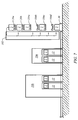
- FIG. 7 is side view of the embodiment shown in FIG. 6 , illustrating the storage system in relation to a tool bay;
- FIG. 8 is an isometric view of yet another embodiment of the present invention.
- FIG. 9 is an isometric view of still another embodiment of the present invention.
- FIGS. 10A-10B provide isometric views of another embodiment of the present invention.
- FIG. 11 is an isometric view of yet another embodiment of the present invention.
- FIGS. 12A-12B are front and side elevation views of another embodiment of the present invention.
- FIGS. 13A-13C illustrate one embodiment of a lane-jumper, in accordance with the present invention
- FIG. 14 illustrates another embodiment of a lane-jumper, in accordance with the present invention.
- FIG. 15 illustrates the lane-jumper shown in FIG. 14 in operation with another embodiment of a conveyor system.
- Container is defined as any structure for supporting an article including, but not limited to, a semiconductor substrate of any size (e.g., 50 mm to 500 mm wafers).
- a container includes a structure that comprises an open volume whereby the article can be accessed (e.g., FPD transport) or a container having a mechanically openable door (e.g., bottom opening SMIF pod and FOUP).
- Load port is defined as any interface equipment that handles containers.
- FIG. 1 illustrates an AMHS including a ceiling-based or interbay conveyor 20 , a floor-based or intrabay conveyor 30 and multiple modular terminals 100 .
- FIG. 1 illustrates two intrabay conveyors 30 , each transporting containers between load ports 12 within its respective tool bay (e.g., tool bays B 1 and B 2 ).
- An arrow indicates the direction that the intrabay conveyor transports containers.
- each intrabay conveyor it is within the scope of the present invention for each intrabay conveyor to comprise a bi-directional conveyor.
- the configuration shown in FIG. 1 is only exemplary. Other configurations are covered by the present invention.
- a ceiling-based conveyor 20 relates to any type of conveyor that transports containers 2 at an elevation above the loading height of a load port 12 .
- a floor-based conveyor 30 relates to any type of conveyor that transports containers 2 at an elevation equal to and below the loading height of a load port 12 .
- FIG. 1 illustrates that each modular terminal 100 , regardless of the configuration, includes a vertical module 102 for transporting containers 2 between a ceiling-based AMHS or transport system and a floor-based AMHS or transport system.
- the terms AMHS and transport system are interchangeable in this description.
- a modular terminal 100 may also include vertically stacked storage shelves 104 to add a storage feature to the modular terminal 100 .
- each set of storage shelves 104 are labeled with a number (e.g., 2, 4, 8) that represents the total number of vertically stacked storage shelves 104 at that specific location.
- modular terminal 100 b includes three sets of storage shelves—two sets of shelves 104 having eight shelves each and one set of storage shelves 104 having four shelves.
- a modular terminal 100 may include any number of storage shelves 104 (including no shelves) and any number of vertical modules 102 .
- FIG. 2 illustrates one embodiment of a ceiling-based conveyor 20 .
- the ceiling-based conveyor 20 comprises an upper conveyor 20 a and a lower conveyor 20 b .
- the two conveyors 20 a and 20 b are stacked vertically such that the longitudinal centerlines CL 1 and CL 2 of each conveyor are substantially horizontally aligned about a common vertical plane 140 .
- each ceiling-based conveyor 20 a and 20 b moves a container 2 in a single direction (indicated by right and left arrows in FIG. 2 ).
- Each conveyor 20 a and 20 b is substantially horizontally aligned with the floor-based intrabay conveyor 30 (e.g., CL 1 , CL 2 and CL 3 are substantially horizontally aligned about a common vertical plane).
- FIG. 1 , CL 2 and CL 3 are substantially horizontally aligned about a common vertical plane.
- FIG. 2 provides only one embodiment of the spatial relationship between the upper interbay conveyor 20 a , the lower interbay conveyor 20 a and the intrabay conveyor 30 .
- the floor-based conveyor 30 may also include a director D for rotating a container 90° between segments of the conveyor.
- a director D is disclosed in U.S. Pat. No. 6,308,818, entitled “Transport System with Integrated Transport Carrier and Director,” which is assigned to Asyst Techriologies, Inc., and is incorporated in its entirety by reference herein.
- the vertical module 102 includes a transfer mechanism that may extend horizontally to the conveyor (either interbay or intrabay conveyors), engage a container 2 (e.g., by the bottom surface or the top handle of the container), lift a container 2 off the conveyor, place a container on the conveyor, and move a container 2 into/out of and within the vertical module 102 . If the transfer mechanism cannot rotate (e.g., about a theta axis), the transfer mechanism is limited to storing containers 2 only in storage shelves/locations 104 that are located between the interbay and intrabay conveyors (e.g., FIG. 4 embodiment) or at a location on the opposite side of the vertical module 102 (e.g., FIG. 9 embodiment).
- the transfer mechanism may require theta or linear motion about two different axes. This would greatly increase the storage density of the modular terminal 100 .
- any storage locations on the side of the vertical module 102 opposite the interbay conveyor 20 may not be very desirable because the locations may block service access to the vertical module 102 and decrease usable tool space in the tool bay.
- FIG. 1 illustrates a modular, expandable architecture with a capability that can cover a wide range of intrabay throughput requirements.
- the modular terminal 100 could be configured with only a single vertical module 102 and a minimum number of storage shelves/locations 104 .
- the vertical module 102 may also be configured without any storage shelves 104 and used solely for inter-conveyor transportation (e.g., between a ceiling based conveyor and a floor-based conveyor).
- a single vertical module 102 (with or without storage shelves), with a transfer mechanism having theta, vertical and horizontal motion, may eliminate the section of floor-based or intrabay conveyor 30 (shown in FIG. 2 ) that lies directly beneath the interbay conveyor 20 .
- the transfer mechanism in the vertical module 102 can move a container 2 in many directions.
- the transfer mechanism may raise to the level of the upper interbay conveyor 20 a , extend a gripper or other device outward to engage the container 2 , raise the gripper upward to lift the container 2 off the interbay conveyor 20 , move the container 2 into the vertical module 102 , drop to the level of the desired storage shelf 104 or the floor-based conveyor 30 , and place the container 2 directly on the shelf 104 or floor-based conveyor 30 .
- each shelf 104 comprises a conveyor for moving a container 2 in either direction on the shelf (as shown by the arrows).
- FIG. 5 each shelf 104 comprises a conveyor for moving a container 2 in either direction on the shelf (as shown by the arrows).
- the transfer mechanism would remove a container 2 from the upper conveyor 20 a (or lower conveyor 20 b ) and move the container 2 into the vertical module 102 .
- the transfer mechanism would then lower the container 2 down to storage shelf 104 e , for example, and place the container 2 on the storage shelf 104 e .
- Many other movements of a container are within the scope of the present invention.
- FIG. 1 also illustrates an embodiment of a pull-over loop 120 .
- Each pull-over loop 120 may be positioned either upstream or downstream of a modular terminal 100 to provide a temporary storage area.
- a pull-over loop 120 may be positioned anywhere along the conveyor.
- a pull-over loop may be positioned adjacent only the upper interbay conveyor 20 a or a pull-over loop 120 may be positioned adjacent both the upper interbay conveyor 20 a and the lower interbay conveyor 20 b .
- the AMHS could quickly transfer the container 2 from the conveyor to the pull-over loop 120 . Moving the container off of the conveyor avoids stopping the interbay conveyor 20 until the vertical module 102 is ready to accept the container. Other containers on the conveyor could then pass the pull-over loop 120 and continue moving towards their destination.
- the container could then be placed back onto the conveyor without interrupting the flow of the AMHS.
- a pull-over loop 120 generally comprises a conveyor 122 for temporarily buffering arriving containers 2 .
- Other mechanisms known within the art for buffering containers are also within the scope of the invention.
- a lane-jumper 126 generally comprises any mechanism that transfers a container 2 between two conveyors (e.g., between the pull-over loop conveyor 122 and the interbay conveyor 20 ) or other AMHS. For example, a container 2 traveling on the ceiling-based conveyor 20 is briefly stopped, gripped, lifted off the interbay conveyor 20 , and then moved over the pull-over loop conveyor 122 .
- a mechanism for transferring the container 2 between conveyors could comprise, for example, a single or multi-segmented arm or a linear slide.
- a separate mechanism could be used to lift the container from underneath, allowing more variations in the design of the lateral transfer mechanism.
- Other robotic mechanisms known within the art for transferring containers are within the scope of the invention.
- interbay conveyor 20 e.g., upper interbay conveyor 20 a and lower interbay conveyor 20 b
- the interbay conveyor 20 will, however, most efficiently deliver containers if the container motion is uni-directional.
- Multiple parallel interbay conveyors 20 also increase the interbay AMHS throughput. It is preferable to have at least one conveyor for each interbay direction to efficiently transfer containers between any two bays (see FIG. 4 embodiment).
- Conventional planar interbay conveyor architecture does not allow a container traveling on the conveyor located further from the tool bay to enter the tool bay without intersecting the conveyor closer to the tool bay.
- FIG. 3 illustrates another AMHS utilizing various components of the present invention to improve the overall throughput of containers within the fabrication facility.
- the AMHS includes a ceiling-based conveyor 20 , multiple floor-based conveyors 30 and tool bays B 1 and B 2 .
- Several modular terminals 100 are placed along the ceiling-based conveyor 20 .
- the locations of the modular terminals 100 and the other components of the AMHS are for exemplary purposes only.
- FIG. 3 illustrates that the containers 2 may be stored in the AMHS with the modular terminals 100 .
- FIGS. 4-7 illustrate various combinations of modular terminals 100 that provide, among other things, vertical transfer, storage and buffering of containers 2 .
- the vertical module 100 may include no storage shelves.
- FIG. 4 illustrates one embodiment of modular terminal 100 providing several space saving features.
- the modular terminal 100 includes a first vertical module 102 a , a second vertical module 102 b , four storage shelves 104 a - 104 d , a first transfer platform 106 and a second transfer platform 108 .
- FIG. 4 illustrates that the interbay conveyors 20 a and 20 b , and the storage shelves 104 a - 104 d , are each horizontally aligned with a vertical plane 150 .
- the modular terminal 100 may, of course, have other configurations.
- FIG. 4 illustrates that each vertical module 102 comprises a housing 110 that extends between the upper interbay conveyor 20 a and the uppermost storage shelf 104 a .
- the housing 110 of each vertical module 102 does not have to extend between the same interbay conveyor 20 or storage shelf 104 , and does not have to be adjacent each other.
- the modular terminal 100 may only include a single vertical module 102 .
- the modular terminal 100 may include any number of storage shelves 104 (including none).
- a transfer mechanism (not shown in FIG. 4 ) travels within each housing 110 to move a container 2 between the conveyor(s) and the storage shelves 104 .
- Each storage shelf 104 shown in FIG. 4 comprises a conveyor for moving a container 2 between anywhere along the storage shelf.
- the storage shelf 104 a is able to move a container 2 between the first end 104 a 1 and the second end 104 a 2 .
- the uppermost shelf 104 a similar to the other storage shelves 104 b - 104 d , may be a unidirectional or a bidirectional conveyor.
- the modular terminal 100 shown in FIG. 4 moves a container from either the upper conveyor 20 a or the lower conveyor 20 b initially to the uppermost storage shelf 104 a .
- the container 2 may be moved to another storage shelf (e.g., shelves 104 a , 104 b , 104 c and 104 d in FIG. 4 ) by either transfer platform 106 or a combination of transfer platforms 106 and 108 .
- the transfer platform 106 will eventually lower the container 2 down to the floor-based conveyor 30 .
- More than one vertical module 102 in a single modular terminal 100 improves the efficiency of the modular terminal 100 .
- containers can be unloaded with higher throughput from the interbay conveyor 20 because there are multiple transfer mechanisms working in parallel.
- the scalable, parallel architecture reduces the average time it takes to remove containers from the ceiling-based conveyor 20 .
- the transfer platforms 106 and 108 are preferably positioned in-line with the end of each storage shelf 104 and located directly underneath the interbay conveyor 20 . The transfer platforms may be located in other positions too.
- Each vertical module 102 may also directly access any number of the storage shelves 104 a - 104 d .
- the vertical modules 102 could, for example, move a container 2 directly between the ceiling-based conveyor 20 and the floor-based conveyor 30 .
- full-length vertical modules 102 could be mounted to the sides of each storage shelf 104 to replace the in-line platforms 106 and 108 .
- the vertical modules 102 shown in FIG. 4 illustrate that the platform 106 may access all of the storage shelves 104 a - 104 d while the platform 108 cannot access the uppermost storage shelf 104 a .
- the two transfer platforms prevents each storage shelf 104 from operating as a first in, first out (FIFO) system.
- FIFO first in, first out
- Containers stored on, for example, a storage shelf 104 may exit either the first end 104 d 1 to transfer platform 108 or exit the second end 104 d 2 to the transfer platform 106 .
- Each transfer platform 106 and 108 preferably comprises a bidirectional conveyor in order to be able to move a container 2 between itself and a storage shelf 104 .
- FIG. 5 illustrates an upper ceiling-based conveyor 20 a and a lower ceiling-based conveyor 20 b linked with multiple vertical modules 102 a - 102 c , and an optional platform 106 .
- Each vertical module 102 a - 102 c may be located on the near side of the ceiling-based conveyor 20 (as shown in FIG. 5 ), on the far side of the ceiling-based conveyor 20 (similar to FIG. 4 ), or on both sides of the ceiling-based conveyor 20 .
- the method of operation comprises a first-in, first-out (“FIFO”) method that provides buffering, but not true random access storage.
- FIFO first-in, first-out
- a vertical module 102 transfers a container 2 from one of the interbay conveyors 20 a or 20 b to one of the vertically stacked storage shleves 104 a - 104 e .
- the storage shelf 104 then moves the container 2 to the end of the storage shelf towards the platform 106 (see arrows in FIG. 5 ).
- the container 2 after placed on the platform 106 , is then transferred to the floor-based conveyor 30 .
- the container 2 may be transferred from a storage shelf 104 to the floor-based conveyor 30 by either by the platform 106 or a vertical module 102 (if the vertical module 102 extends to a the floor-based conveyor 30 ).
- vertical module 102 a may extend between the ceiling-based conveyor 20 and the floor-based conveyor 30 .
- the vertical module 102 b may extend from the ceiling-based conveyor 20 to the storage shelf 104 c .
- the vertical module 102 c may extend from the ceiling-based conveyor 20 only to the uppermost storage shelf 104 a .
- Other configurations of the vertical modules 102 are within the scope of this invention.
- a vertical module 102 could also be positioned at either end of the storage shelves 104 .
- a vertical module 102 could replace the platform 106 .
- a vertical module 102 could also be located at the other end of the storage shelves 104 .
- the transfer mechanism in each vertical module 102 may comprise a short section of conveyor or a transfer mechanism (e.g., container handling robot) for transferring the container 2 between the vertical module 102 and the storage shelf 104 . It is also within the scope of the invention to place an interbay conveyor 20 or additional storage shelves 104 (see FIG. 9 configuration) on either side of each vertical module 102 (see FIG. 10B configuration).
- FIGS. 6-7 illustrate a random access container storage system does not use a vertical module 102 located at either end of the storage conveyors 104 .
- Vertical modules 102 a - 102 c connect interbay conveyors 20 a and 20 b with storage shelves 104 a - 104 d as well as floor-based conveyor 30 .
- Containers 2 are shown on all levels of the storage shelves 104 except storage shelves 104 b and 104 d . Individual storage positions along storage shelves 104 a - 104 d are identified with letters a through k.
- the floor-based intrabay conveyor 30 may be the same as the conveyor shown in FIG. 2 , but is not limited to that embodiment.
- Tool bays require an aisle space, which is shown in FIG. 6 as aisle space 13 .
- Each storage shelf 104 requires a certain minimum number of open spaces so that the containers 2 stored on the storage shelf 104 can be moved laterally to either vertical module 102 a , 102 b or 102 c for eventual delivery to the floor-based conveyor 30 .
- the FIG. 6 embodiment of the storage system includes an equal number of storage locations between each vertical module 102 (e.g., two storage locations between each vertical module 102 are shown) as each storage shelf 104 extends beyond the vertical modules 102 at the ends for additional container storage.
- the storage system may also have other configurations to store more/less containers.
- This type of modular terminal 100 could be optimized for maximum storage density, maximum storage or throughput by varying the number of vertical modules 102 and their spacing.
- FIG. 6 illustrates that the storage shelf 104 a has a maximum number of storage locations occupied by containers 2 that still allow for any of the containers 2 to be removed from storage shelf 104 a .
- the container 2 stored in location k needs to be unloaded from storage shelf 104 a , all nine containers must be shifted to the left two locations to move the container 2 stored in location k to location i.
- Location i is accessible by vertical module 102 c and therefore, the container 2 may be moved off of storage shelf 104 a to another storage shelf 104 , a ceiling-based conveyor 20 or the floor-based conveyor 30 . Not all of the containers 2 stored on storage shelf 104 a always have to be moved to place a container 2 in a vertical module accessible position.
- Storage shelf 104 c has less than the maximum number of storage locations occupied by a container 2 , and the containers 2 are stored in the most efficient locations. For example, any of the containers 2 stored on storage shelf 104 c may be retrieved without having to move the other containers 2 .
- the optimum operation of this type of modular terminal 100 positions containers 2 only in the locations that would, on average, allow retrieval of a container 2 with the minimum shifting of the other containers 2 .
- a container 2 received by a vertical module 102 would then be unloaded onto the storage shelf 104 that had the fewest containers.
- the modular terminal 100 would continually shift the containers 2 on a particular storage shelf 104 to the “optimum” positions while the storage shelf 104 is not being accessed—such as the arrangement of containers 2 as shown on storage shelf 104 c.
- FIGS. 8-9 illustrate various configurations of floor-based conveyors 30 to support a bi-directional section of intrabay conveyor and how the modular terminal 100 may service this type of conveyor.
- FIG. 8 illustrates that a container 2 exiting the tool bay on the bi-directional floor-based conveyor 30 will turn at director D 1 , move across the exit conveyor section 32 , turn at director D 3 and then move to director D 4 .
- the containers 2 then wait for a vertical module 102 to become available, and at that time, move from director D 4 to the available vertical module 102 for transport to the interbay conveyor 20 or a storage shelf 104 . Exiting containers 2 could also form a queue on the exit conveyor section 32 , allowing for optimum synchronization with the operation of the vertical modules 102 .
- Containers entering the tool bay from the vertical module 102 would move along the entrance conveyor section 34 , turn at director D 2 , and then engage the bi-directional floor-based conveyor 30 at director D 1 .
- the entrance conveyor section 34 up to director D 2 , could be used as an input queue for containers.
- the intrabay AMHS would control the sequence move directions on the floor-based conveyor 30 .
- the intrabay AMHS may change the bi-directional conveyor direction to “entrance” direction, and then move all containers 2 in the entrance queue. After that, the intrabay AMHS could switch the direction to “exit” direction and move all containers 2 that have been waiting at processing tools or other stockers. It is also within the scope of the invention to switch operation of the bi-directional conveyor 30 based on time intervals or a queue method that has a time limit for each direction.
- FIG. 9 illustrates a system similar to FIG. 8 , except that the exit conveyor section does not connect to the entrance section through D 1 and D 2 .
- each one of the vertical modules 102 includes a mechanism that is capable of accessing both the exit conveyor section 32 and the entrance conveyor section 34 . Exiting containers 2 would queue on the exit conveyor section 32 and directly be unloaded by the vertical module transfer mechanism rather than loop around to the entrance conveyor section 34 as shown in FIG. 8 . Having a transfer mechanism in the vertical modules that can access both the entrance conveyor 34 and exit conveyor 32 also allows more storage conveyors—here shown as storage shelves 104 e and 104 f —to be stacked on the exit conveyor side of the vertical modules 102 .
- FIG. 10A illustrates five storage shelves 104 a - 104 e that are each located below the interbay conveyors 20 a and 20 b .
- Each vertical module 102 a , 102 b and 102 c access a different column of the storage shelves 104 a - 104 e and the entrance conveyor section 34 .
- the containers 2 may be moved between the ceiling-based conveyors 20 , the storage shelves 104 and the entrance conveyor section 34 , by way of example only, with an extending mechanism or robotic arm assembly. The mechanism/assembly is well known within the art and does not require further description in this application.
- each vertical module 102 may also pick up a container 2 from the exit conveyor section 32 directly below it.
- the interbay conveyors 20 discussed above have been vertically stacked, in-line conveyors. It is within the scope of the present invention for the interbay conveyors 20 to have other configurations—including vertically stacked conveyors that are not in-line and/or conveyors that are adjacent to each other at substantially the same height from the facility floor.
- the two interbay conveyors 20 shown in FIG. 10A may be vertically stacked (as shown in FIG. 10A ).
- the two interbay conveyors 20 may alternatively each be located at substantially the same elevation from the facility floor and spaced apart so that the vertical modules 102 are located between the two interbay conveyors 20 (see FIG. 10B ).
- FIG. 10B illustrates that the interbay conveyor 20 a and interbay conveyor 20 b are vertically aligned about a common horizontal plane 160 .
- the two interbay conveyors are not required to be located at the same elevation.
- FIG. 11 illustrates another embodiment of the present invention—modular terminal 200 . Similar to the embodiments described above, the modular terminal 200 may be placed anywhere along an AMHS system.
- the AMHS system shown in FIG. 11 again includes a ceiling-based conveyor 20 and a floor-based conveyor 30 . These two conveyors may be an interbay conveyor or intrabay conveyor.
- the modular terminal 200 includes an upper pass-through zone 206 , a lower pass-through zone 208 and a storage compartment 210 .
- the upper pass-through zone 206 allows the upper conveyor 20 to pass unobstructed through the modular terminal 200 .
- the lower pass-through zone 208 allows the lower-conveyor 30 to pass unobstructed through the modular terminal 200 .
- containers 2 traveling on the respective conveyor may also pass unobstructed through the modular terminal 200 .
- FIG. 11 illustrates that the modular terminal 200 includes two storage compartments 210 a and 210 b .
- each storage compartment 210 includes multiple storage shelves (not shown), and each storage shelf stores two containers 2 side by side.
- the modular terminal 200 may include only one storage shelf or more than two storage shelves. It is also within the scope and spirit of the present invention for the transfer mechanism of the modular terminal 200 to transport a single container or transport multiple containers simultaneously.
- the storage compartments 210 may have other configurations (e.g., more/less shelves, store more than two containers each, etc.).
- the two storage compartments 210 a and 210 b increases the storage capacity of the modular terminal 200 .
- the modular terminal 200 may also include only one storage compartment 210 .
- the transfer mechanism may move two containers simultaneously or comprise two transfer mechanism that may move independently of each other.
- FIG. 11 illustrates a single interbay conveyor 20 passing through the upper pass-though zone 206 of the modular terminal 200 .
- the AMHS system may have multiple, vertically stacked interbay conveyors 20 (similar to the FIG. 4 embodiment), and each conveyor may pass through the modular terminal 200 in the same manner by adding more pass-through zones 206 to the modular terminal 200 .
- AMHS systems include two conveyors.
- a conventional fabrication facility may include only one ceiling-based conveyor 20 .
- the modular terminal 200 would include only an upper pass-through zone 206 and one or more storage compartments 210 . If the modular terminal 200 only includes one storage compartment 210 , the storage compartment 210 is preferably located directly underneath the conveyor 20 (e.g., storage compartment 210 a ) in order to take advantage of the currently unoccupied space in the fabrication facility.
- each vertical module 102 a , 102 b and 102 c shown in FIG. 8 includes its own vertical transfer mechanism for moving a container 2 within the particular vertical module 102 . If each vertical module 102 has a transfer rate of, for example, 70 container moves per hour, the total container moves per hour for the system shown in FIG. 8 is 210 container moves per hour. By adding a fourth vertical module, the system capacity would increase to 280 container moves per hour. Thus, adding additional vertical modules 102 to the system will not affect the transfer rate of each individual vertical module 102 a , 102 b and 102 c.
- a terminal modular 100 including more than one vertical module 102 allows for a flexible control system.
- a single control system may operate all the vertical modules 102 in the modular terminal 100 .
- each vertical module 102 in the modular terminal 100 may have its own control system.
- This plug-and-play control environment allows additional vertical modules 102 to be added to a single module terminal 100 —providing for easy installation, fast start-up time and simple throughput expansion of a modular terminal 100 .
- FIGS. 12A-12B illustrate the modular terminal 200 shown in FIG. 11 in relation to a Direct Load tool.
- FIG. 12A illustrates that each storage shelf in the storage compartment 210 a stores two containers. Each shelf in the storage compartment 210 a may store only one container or more than two containers.
- the containers 2 stored in the storage compartment 210 a are located beneath the ceiling based conveyor 20 b (see FIG. 12B ).
- a transfer device (not shown) moves containers 2 within the travel zone 218 (see FIG. 12B ) between the ceiling-based conveyors 20 a and 20 b , the storage shelves within the storage compartment 210 b and the floor-based conveyor 30 .
- the modular terminal 200 is not required to include storage compartments at all.
- the modular terminal 200 may comprise only a vertical module (e.g., travel zone 218 in FIG. 12B ).
- a container 2 is moved from either a ceiling-based conveyor 20 or a storage shelf down to the floor-based conveyor 30 .
- the floor-based conveyor 30 may then move the container 2 to either load port 12 a , load port 12 b or some other location.
- FIG. 12B illustrates that a container 2 traveling on each of the three conveyors—the ceiling-based conveyor 20 a , the ceiling-based conveyor 20 b or the floor-based conveyor 30 —passes unobstructed through the modular terminal 200 .
- the pass though zone 212 allows containers traveling on the ceiling-based conveyors 20 a and 20 b to pass unobstructed through the modular terminal 200 .
- the pass through zone 214 allows containers traveling on the floor-based conveyor to pass unobstructed through the modular terminal 200 .
- FIG. 12B also illustrates that the modular terminal 200 may include a second storage compartment 210 b.
- FIGS. 13A-13C illustrate one embodiment of a lane-jumper 126 for transferring a FOUP 2 between the ceiling-based conveyor 20 a and the pull-over loop conveyor 122 .
- the lane-jumper 126 comprises a linear transport mechanism 128 including a gripper mechanism 130 and a linear rail or track 132 .
- the gripper mechanism 130 as shown in FIG. 13A , comprises a rigid body 131 and a gripper device 135 .
- the linear track 132 includes a first end 132 a and a second end 132 b .
- a drive mechanism (not shown) moves the rigid body 131 along the linear track 132 between the first end 132 a and the second end 132 b of the track 132 .
- the linear track 132 may be any length as long as the gripper mechanism 130 may engage a container or FOUP 2 seated on both the ceiling-based conveyor 20 a and the loop conveyor 122 .
- the linear transport mechanism 128 is not limited to moving a container between a ceiling-based conveyor 20 a and a loop conveyor 122 .
- the linear transport mechanism 128 amy also move containers between, for example, two floor-based conveyors, two ceiling-based conveyors, and the like. Both conveyors also do not have to be located at the same elevation from the fabrication floor (as shown in FIGS. 13A-13C ).
- FIG. 13A illustrates that the gripper mechanism 130 is able to move along a vertical direction (indicated by arrow 140 ) and a horizontal direction (indicated by arrow 142 ).
- FIG. 13A illustrates that the gripper device 135 engages the FOUP's top handle 6 . It is within the scope and spirit of the present invention for the gripper 130 to engage other parts of the FOUP such as, but not limited to, the FOUP's side handles or the bottom support plate.
- the gripper device 135 is aligned with the FOUP handle 6 and is vertically lowered (arrow 140 ) until the gripper device 135 is able to engage and secure the FOUP handle 6 .
- the gripper mechanism 130 then lifts the FOUP 2 off the ceiling-based conveyor 20 a .
- the FOUP 2 is then moved horizontally towards the conveyor 122 (see FIG. 13B ) until the FOUP 2 is aligned with the conveyor 122 below.
- the gripper mechanism 130 then lowers the gripper device 135 until the FOUP 2 is seated on the conveyor 122 .
- the gripper device 135 may comprise either an active gripping mechanism or a passive gripping mechanism.
- An active gripping mechanism may comprise, for example, a robotic mechanism that secures or grips the FOUP's top handle 6 .
- a passive gripper device 135 may operate in several ways. For example, the gripper device 135 moves into a “grip position” above the ceiling-based conveyor 20 a and waits for a FOUP 2 traveling along the ceiling-based conveyor 20 a until the FOUP handle 6 engages the passive gripper device 135 . At that point, the gripper device 135 raises vertically and lifts the FOUP 2 off the ceiling-based conveyor 20 a . In the alternative, the gripper device 135 waits for a FOUP 2 traveling along a conveyor to come to rest. The gripper device 135 then approaches the FOUP 2 from the side and engages the FOUP handle 6 , and then lifts the FOUP 2 from the conveyor.
- Each type of gripping mechanism is known within the art and therefore, no further description of the mechanisms is required
- FIGS. 13A-13C illustrate one embodiment of a lane-jumper 128 for moving a FOUP 2 between a ceiling-based conveyor 20 a and a pull-over loop conveyor 122 .
- the configuration of the conveyors 20 a and 122 are for illustrative purposes only.
- the conveyors 20 a and 122 may be located further apart, at different elevations from the fab floor (e.g., conveyor 20 a comprises a ceiling-base conveyor while the conveyor 122 comprises a floor-based conveyor), and so on.
- the lane-jumper 128 may even move FOUPs 2 between any two conveyors.
- the lane-jumper 128 (and other embodiments of a lane-jumper described herein) is not limited to moving FOUPs between a ceiling-based conveyor 20 a and a loop conveyor 122 .
- the lane-jumper may move a FOUP 2 between any two transport systems. If the conveyors 20 a and 122 were separated further apart than the width of a FOUP 2 , the lane-jumper 128 could temporarily maintain the FOUP 2 between the ceiling-based conveyor 20 a and the loop conveyor 122 without obstructing traffic on either conveyor. This feature would allow the lane-jumper 128 to immediately remove a FOUP 2 from the ceiling-based conveyor 20 a even if there was no place to put the FOUP 2 on the loop conveyor 122 . The FOUP 2 could remain temporarily located between the ceiling-based conveyor 20 a and loop conveyor 122 until there was a space available on the loop conveyor 122 .
- the gripper 130 may comprise either a passive gripper or an active gripper.
- FIG. 13A illustrates the gripper 130 engaged with the FOUP handle 6 .
- FIG. 13B shows that the gripper 130 has been raised (shown by arrow 140 ) in order to lift the FOUP 2 off the ceiling-based conveyor 20 a , and has begun to move the FOUP 2 towards the loop conveyor 122 .
- the gripper 130 moves horizontally along a track 132 (shown by arrow 142 ).
- FIG. 13C shows that the lane-jumper 128 has lowered the gripper 130 in order to set the FOUP 2 onto the loop conveyor 122 .
- FIG. 14 illustrates another embodiment of a lane-jumper 300 .
- the lane-jumper 300 includes a rotating arm link rather than a linear mechanism (as shown in FIGS. 13A-13C ) to move a FOUP 2 between the ceiling-based conveyor 20 a and the conveyor 122 .
- the lane-jumper 300 includes a center hub 302 , an arm 304 , a wrist joint 306 and a gripper 308 .
- the arm 304 connects the wrist joint 206 to the hub 302 .
- the gripper 306 is rotatably connected to the wrist joint 306 . Similar to the lane-jumper 126 shown in FIGS. 13A , the gripper 306 engages the FOUP handle 6 .
- the gripper 306 may also engage or secure other part of the FOUP 2 .
- the center hub 302 and/or the wrist joint 208 may be able to move vertically in order to raise a FOUP 2 off a conveyor and/or set a FOUP 2 on a conveyor.
- the gripper 308 engages the top handle 6 of the FOUP 2 seated on the conveyor 20 a (shown as position A).
- position A the FOUP 2 is lifted off of the ceiling-based conveyor 20 a and rotated to position C (intermediate position B is shown to illustrate the complete motion of the FOUP).
- the FOUP 2 is then lowered onto conveyor 122 .
- the rotation of the wrist joint 306 is preferably coordinated with the rotation of the center hub 302 in order to maintain the alignment of the FOUP as shown in positions A, B and C (e.g., the FOUP door 4 is constantly facing the same direction).
- the conveyors 20 a and 122 may be separated by any distance. However, the distance between the ceiling-based conveyor 20 a and the conveyor 122 , as shown in FIG. 14 , is a minimum distance that allows the FOUP 2 to remain in position B without obstructing the traffic on either conveyor (e.g., a distance slightly greater than the width of a FOUP).
- FIG. 15 illustrates how the lane jumper 300 may also transfer a FOUP 2 between a ceiling-based conveyor 20 a and a pull-over loop conveyor 122 that is perpendicular to the ceiling-based conveyor 20 a .
- the lane jumper 300 may move a FOUP 2 between other conveyors.
- FIG. 15 illustrates that a FOUP 2 located at position D on the ceiling-based conveyor 20 a is configured such that the FOUP door 4 is substantially parallel with the conveyor rails.
- the FOUP door 4 of the FOUP 2 located at position E on the conveyor 122 is also parallel to the conveyor rails of conveyor 122 .
- the FOUP 2 has effectively been rotated 90 degrees during transfer from position D to position E.
- the wrist joint 306 of the lane jumper 300 shown in FIG. 15 may remain stationary (is not required to rotate) with respect to the arm 304 during transfer of a FOUP 2 between the ceiling-based conveyor 20 a and the pull-over loop conveyor 122 .
- the non rotating wrist joint 306 is possible with a fixed arm length when the conveyors 20 a and 122 are positioned such that the arm 304 , when rotated 90 degrees (e.g., from position D to position E), can set a FOUP 2 on the conveyor solely through vertical motion.
- the wrist joint 306 would be required to rotate if, for example, the arm 304 is required to rotate through more or less than 90 degrees.
- a lane-jumper could be supported from a ceiling-based frame or a floor-based frame. Either method of support can be used in connection with both a ceiling-based conveyor and a floor-based conveyor, or from the conveyor structure itself.
Abstract
Description
M=T−E=N*(X+1)
-
- N=Number of vertical modules in the storage system;
- X=Number of container storage locations located between each vertical module or at the end of the storage conveyor section;
- T=N*(X+1)+X=Total number of container storage locations per storage conveyor level; and
- E=minimum number of container storage locations left empty per storage conveyor level.
Claims (31)
Priority Applications (1)
| Application Number | Priority Date | Filing Date | Title |
|---|---|---|---|
| US11/433,980 US7798759B2 (en) | 2005-05-16 | 2006-05-15 | Modular terminal for high-throughput AMHS |
Applications Claiming Priority (3)
| Application Number | Priority Date | Filing Date | Title |
|---|---|---|---|
| US68138905P | 2005-05-16 | 2005-05-16 | |
| US69778505P | 2005-07-08 | 2005-07-08 | |
| US11/433,980 US7798759B2 (en) | 2005-05-16 | 2006-05-15 | Modular terminal for high-throughput AMHS |
Publications (2)
| Publication Number | Publication Date |
|---|---|
| US20070128007A1 US20070128007A1 (en) | 2007-06-07 |
| US7798759B2 true US7798759B2 (en) | 2010-09-21 |
Family
ID=36968681
Family Applications (1)
| Application Number | Title | Priority Date | Filing Date |
|---|---|---|---|
| US11/433,980 Expired - Fee Related US7798759B2 (en) | 2005-05-16 | 2006-05-15 | Modular terminal for high-throughput AMHS |
Country Status (6)
| Country | Link |
|---|---|
| US (1) | US7798759B2 (en) |
| EP (1) | EP1883958A2 (en) |
| JP (1) | JP5152700B2 (en) |
| KR (1) | KR100965525B1 (en) |
| CN (1) | CN101223635B (en) |
| WO (1) | WO2006124683A2 (en) |
Cited By (3)
| Publication number | Priority date | Publication date | Assignee | Title |
|---|---|---|---|---|
| US20120118699A1 (en) * | 2008-07-30 | 2012-05-17 | Rainer Buchmann | Scalable shipping buffer having an integrated sorting function and corresponding method |
| US10759603B2 (en) | 2016-10-25 | 2020-09-01 | Hotberry, Llc | Apparatus, system, and method for a drive-through grocery service |
| US11279559B1 (en) | 2017-10-24 | 2022-03-22 | Hotberry, Llc | Intelligent shelves for automated distribution of products |
Families Citing this family (16)
| Publication number | Priority date | Publication date | Assignee | Title |
|---|---|---|---|---|
| US7410340B2 (en) * | 2005-02-24 | 2008-08-12 | Asyst Technologies, Inc. | Direct tool loading |
| US20090067957A1 (en) * | 2007-09-06 | 2009-03-12 | Mitsuhiro Ando | Transport system with buffering |
| US7992734B2 (en) * | 2008-01-11 | 2011-08-09 | International Business Machines Corporation | Semiconductor automation buffer storage identification system and method |
| US9214372B2 (en) * | 2008-08-28 | 2015-12-15 | Tokyo Ohka Kogyo Co., Ltd. | Substrate processing system, carrying device and coating device |
| US8882433B2 (en) | 2009-05-18 | 2014-11-11 | Brooks Automation, Inc. | Integrated systems for interfacing with substrate container storage systems |
| CN102460675B (en) * | 2009-05-18 | 2015-04-29 | 布鲁克斯自动化公司 | Integrated systems for interfacing with substrate container storage systems |
| EP2433299B1 (en) | 2009-05-18 | 2022-10-26 | Brooks Automation US, LLC | Substrate container storage system |
| US8275480B2 (en) * | 2009-11-17 | 2012-09-25 | Toyota Motor Engineering & Manufacturing North America, Inc. | Methods and systems for transporting parts from a primary process to a secondary process in a first in, first out fashion |
| US8677929B2 (en) * | 2010-12-29 | 2014-03-25 | Intevac, Inc. | Method and apparatus for masking solar cell substrates for deposition |
| US9558978B2 (en) | 2012-05-04 | 2017-01-31 | Kla-Tencor Corporation | Material handling with dedicated automated material handling system |
| WO2015109315A2 (en) * | 2014-01-20 | 2015-07-23 | Brooks Automation, Inc. | Portable cryogenic workstation |
| KR20230027331A (en) * | 2015-04-15 | 2023-02-27 | 오카도 이노베이션 리미티드 | Object handling system and method |
| SG11201811531XA (en) * | 2016-03-22 | 2019-01-30 | Shinkawa Kk | Substrate supply unit and bonding apparatus |
| CN109941658B (en) * | 2017-12-20 | 2020-09-01 | 北京京东振世信息技术有限公司 | Cargo transmission system, method and device |
| US11011402B2 (en) * | 2018-06-27 | 2021-05-18 | Taiwan Semiconductor Manufacturing Company Ltd. | Transport system of semiconductor fabrication facility, associated movable container and method |
| JP7255615B2 (en) * | 2021-01-29 | 2023-04-11 | 村田機械株式会社 | conveyor system |
Citations (26)
| Publication number | Priority date | Publication date | Assignee | Title |
|---|---|---|---|---|
| US3403799A (en) * | 1966-04-14 | 1968-10-01 | Int Standard Electric Corp | Arrangement to load a conveying route |
| US5411358A (en) | 1992-08-04 | 1995-05-02 | International Business Machines Corporation | Dispatching apparatus with a gas supply distribution system for handling and storing pressurized sealable transportable containers |
| US5473978A (en) * | 1992-02-24 | 1995-12-12 | Colombo Filippetti S.R.L. | Method for the transit of small objects within treatment chambers, and means for its implementation |
| US5980183A (en) | 1997-04-14 | 1999-11-09 | Asyst Technologies, Inc. | Integrated intrabay buffer, delivery, and stocker system |
| US6039169A (en) * | 1998-05-05 | 2000-03-21 | Gima S.P.A. | Multilevel storage device for containers, in particular CD cases |
| JP2000124284A (en) | 1998-10-13 | 2000-04-28 | Hitachi Kiden Kogyo Ltd | Transfer apparatus |
| US6089811A (en) * | 1998-12-25 | 2000-07-18 | Fujitsu Limited | Production line workflow and parts transport arrangement |
| US20010043849A1 (en) * | 1998-12-01 | 2001-11-22 | Ilya Perlov | Apparatus for storing and moving a cassette |
| US6468021B1 (en) | 1998-12-18 | 2002-10-22 | Asyst Technologies, Inc. | Integrated intra-bay transfer, storage, and delivery system |
| US20020187024A1 (en) * | 2001-06-12 | 2002-12-12 | Applied Materials, Inc. | Apparatus for storing and moving a carrier |
| US6579052B1 (en) * | 1997-07-11 | 2003-06-17 | Asyst Technologies, Inc. | SMIF pod storage, delivery and retrieval system |
| US20030161714A1 (en) * | 2000-07-06 | 2003-08-28 | Jakob Blattner | Storage and buffer system with transport elements |
| US6677690B2 (en) | 2001-02-02 | 2004-01-13 | Asyst Technologies, Inc. | System for safeguarding integrated intrabay pod delivery and storage system |
| US6681916B2 (en) * | 1999-05-06 | 2004-01-27 | Tokyo Electron Limited | Transfer system for conveying LCD glass substrate |
| US20040081546A1 (en) | 2002-08-31 | 2004-04-29 | Applied Materials, Inc. | Method and apparatus for supplying substrates to a processing tool |
| US20040091338A1 (en) * | 2000-04-12 | 2004-05-13 | Kim Ki-Sang | Transfer system and apparatus for workpiece containers and method of transferring the workpiece containers using the same |
| US20040109746A1 (en) | 2002-12-09 | 2004-06-10 | Murata Kikai Kabushiki Kaisha | Overhead travelling carriage system |
| US20040166689A1 (en) | 2001-04-19 | 2004-08-26 | Takayuki Wakabayashi | Method of fabrication of semiconductor integrated circuit device |
| JP2004238089A (en) | 2003-02-03 | 2004-08-26 | Murata Mach Ltd | Stocker |
| US6955197B2 (en) | 2002-08-31 | 2005-10-18 | Applied Materials, Inc. | Substrate carrier having door latching and substrate clamping mechanisms |
| US6979168B2 (en) * | 2002-03-26 | 2005-12-27 | Hitachi High-Technologies Corporation | Method and apparatus for transferring substrate |
| US6990721B2 (en) * | 2003-03-21 | 2006-01-31 | Brooks Automation, Inc. | Growth model automated material handling system |
| US7032736B2 (en) * | 2003-03-19 | 2006-04-25 | Cavanna S.P.A. | Device for conveying products, particularly for automatic packaging machinery, and corresponding method of use |
| US7168905B1 (en) * | 2005-08-01 | 2007-01-30 | Worthwhile Products | Storage and retrieval system |
| US20070264114A1 (en) * | 2006-05-09 | 2007-11-15 | Taiwan Semiconductor Manufacturing Co., Ltd. | High efficiency buffer stocker |
| US7364028B2 (en) * | 2003-12-04 | 2008-04-29 | Daifuku Co., Ltd. | Glass substrate transporting facility |
Family Cites Families (7)
| Publication number | Priority date | Publication date | Assignee | Title |
|---|---|---|---|---|
| JP3669057B2 (en) * | 1996-06-03 | 2005-07-06 | アシスト シンコー株式会社 | Transport system to stocker |
| JP2000159304A (en) * | 2000-01-01 | 2000-06-13 | Advanced Display Inc | Method for carrying cassette and automated storage and retrieval system using the method |
| JP3074688U (en) * | 2000-07-07 | 2001-01-19 | 壽春 黒山 | Auto track equipment |
| JP2002114324A (en) * | 2000-10-06 | 2002-04-16 | Mitsubishi Heavy Ind Ltd | Warehouse facility |
| US6854583B1 (en) * | 2001-02-06 | 2005-02-15 | Middlesex General Industries, Inc. | Conveyorized storage and transportation system |
| JP2004307125A (en) * | 2003-04-04 | 2004-11-04 | Asyst Shinko Inc | Storage shelf device |
| JP4470576B2 (en) * | 2003-05-20 | 2010-06-02 | ムラテックオートメーション株式会社 | Transport system |
-
2006
- 2006-05-15 EP EP06759761A patent/EP1883958A2/en not_active Withdrawn
- 2006-05-15 KR KR1020077029508A patent/KR100965525B1/en active IP Right Grant
- 2006-05-15 US US11/433,980 patent/US7798759B2/en not_active Expired - Fee Related
- 2006-05-15 JP JP2008512381A patent/JP5152700B2/en not_active Expired - Fee Related
- 2006-05-15 CN CN2006800255004A patent/CN101223635B/en not_active Expired - Fee Related
- 2006-05-15 WO PCT/US2006/018568 patent/WO2006124683A2/en active Application Filing
Patent Citations (26)
| Publication number | Priority date | Publication date | Assignee | Title |
|---|---|---|---|---|
| US3403799A (en) * | 1966-04-14 | 1968-10-01 | Int Standard Electric Corp | Arrangement to load a conveying route |
| US5473978A (en) * | 1992-02-24 | 1995-12-12 | Colombo Filippetti S.R.L. | Method for the transit of small objects within treatment chambers, and means for its implementation |
| US5411358A (en) | 1992-08-04 | 1995-05-02 | International Business Machines Corporation | Dispatching apparatus with a gas supply distribution system for handling and storing pressurized sealable transportable containers |
| US5980183A (en) | 1997-04-14 | 1999-11-09 | Asyst Technologies, Inc. | Integrated intrabay buffer, delivery, and stocker system |
| US6579052B1 (en) * | 1997-07-11 | 2003-06-17 | Asyst Technologies, Inc. | SMIF pod storage, delivery and retrieval system |
| US6039169A (en) * | 1998-05-05 | 2000-03-21 | Gima S.P.A. | Multilevel storage device for containers, in particular CD cases |
| JP2000124284A (en) | 1998-10-13 | 2000-04-28 | Hitachi Kiden Kogyo Ltd | Transfer apparatus |
| US20010043849A1 (en) * | 1998-12-01 | 2001-11-22 | Ilya Perlov | Apparatus for storing and moving a cassette |
| US6468021B1 (en) | 1998-12-18 | 2002-10-22 | Asyst Technologies, Inc. | Integrated intra-bay transfer, storage, and delivery system |
| US6089811A (en) * | 1998-12-25 | 2000-07-18 | Fujitsu Limited | Production line workflow and parts transport arrangement |
| US6681916B2 (en) * | 1999-05-06 | 2004-01-27 | Tokyo Electron Limited | Transfer system for conveying LCD glass substrate |
| US20040091338A1 (en) * | 2000-04-12 | 2004-05-13 | Kim Ki-Sang | Transfer system and apparatus for workpiece containers and method of transferring the workpiece containers using the same |
| US20030161714A1 (en) * | 2000-07-06 | 2003-08-28 | Jakob Blattner | Storage and buffer system with transport elements |
| US6677690B2 (en) | 2001-02-02 | 2004-01-13 | Asyst Technologies, Inc. | System for safeguarding integrated intrabay pod delivery and storage system |
| US20040166689A1 (en) | 2001-04-19 | 2004-08-26 | Takayuki Wakabayashi | Method of fabrication of semiconductor integrated circuit device |
| US20020187024A1 (en) * | 2001-06-12 | 2002-12-12 | Applied Materials, Inc. | Apparatus for storing and moving a carrier |
| US6979168B2 (en) * | 2002-03-26 | 2005-12-27 | Hitachi High-Technologies Corporation | Method and apparatus for transferring substrate |
| US20040081546A1 (en) | 2002-08-31 | 2004-04-29 | Applied Materials, Inc. | Method and apparatus for supplying substrates to a processing tool |
| US6955197B2 (en) | 2002-08-31 | 2005-10-18 | Applied Materials, Inc. | Substrate carrier having door latching and substrate clamping mechanisms |
| US20040109746A1 (en) | 2002-12-09 | 2004-06-10 | Murata Kikai Kabushiki Kaisha | Overhead travelling carriage system |
| JP2004238089A (en) | 2003-02-03 | 2004-08-26 | Murata Mach Ltd | Stocker |
| US7032736B2 (en) * | 2003-03-19 | 2006-04-25 | Cavanna S.P.A. | Device for conveying products, particularly for automatic packaging machinery, and corresponding method of use |
| US6990721B2 (en) * | 2003-03-21 | 2006-01-31 | Brooks Automation, Inc. | Growth model automated material handling system |
| US7364028B2 (en) * | 2003-12-04 | 2008-04-29 | Daifuku Co., Ltd. | Glass substrate transporting facility |
| US7168905B1 (en) * | 2005-08-01 | 2007-01-30 | Worthwhile Products | Storage and retrieval system |
| US20070264114A1 (en) * | 2006-05-09 | 2007-11-15 | Taiwan Semiconductor Manufacturing Co., Ltd. | High efficiency buffer stocker |
Non-Patent Citations (3)
| Title |
|---|
| International Technology Roadmap for Semiconductors (ITRS 2003), Factory Integration Chapter, Material Handling Backup Section, 2003 Public Presentation, Sep. 4, 2003. |
| Patent Abstracts of Japan, Dec. 5, 2003, vol. 2003, No. 12. |
| Patent Abstracts of Japan, Sep. 29, 2000, vol. 2000, No. 07. |
Cited By (7)
| Publication number | Priority date | Publication date | Assignee | Title |
|---|---|---|---|---|
| US20120118699A1 (en) * | 2008-07-30 | 2012-05-17 | Rainer Buchmann | Scalable shipping buffer having an integrated sorting function and corresponding method |
| US8397898B2 (en) * | 2008-07-30 | 2013-03-19 | Rainer Buchmann | Scalable shipping buffer having an integrated sorting function and corresponding method |
| US10759603B2 (en) | 2016-10-25 | 2020-09-01 | Hotberry, Llc | Apparatus, system, and method for a drive-through grocery service |
| US11358795B2 (en) | 2016-10-25 | 2022-06-14 | Hotberry, Llc | System and methods for assembling grocery orders |
| US11597599B2 (en) | 2016-10-25 | 2023-03-07 | Hotberry, Llc | Apparatus, system, and method for a drive-through grocery service |
| US11279559B1 (en) | 2017-10-24 | 2022-03-22 | Hotberry, Llc | Intelligent shelves for automated distribution of products |
| US11702286B2 (en) | 2017-10-24 | 2023-07-18 | Hotberry, Llc | Intelligent shelves for automated distribution of products |
Also Published As
| Publication number | Publication date |
|---|---|
| KR100965525B1 (en) | 2010-06-23 |
| WO2006124683A2 (en) | 2006-11-23 |
| US20070128007A1 (en) | 2007-06-07 |
| KR20080025068A (en) | 2008-03-19 |
| JP2008540299A (en) | 2008-11-20 |
| WO2006124683A3 (en) | 2007-03-22 |
| CN101223635B (en) | 2010-05-19 |
| CN101223635A (en) | 2008-07-16 |
| EP1883958A2 (en) | 2008-02-06 |
| JP5152700B2 (en) | 2013-02-27 |
Similar Documents
| Publication | Publication Date | Title |
|---|---|---|
| US7798759B2 (en) | Modular terminal for high-throughput AMHS | |
| US10593583B2 (en) | Integrated systems for interfacing with substrate container storage systems | |
| US7780392B2 (en) | Horizontal array stocker | |
| US20070010909A1 (en) | Stocker | |
| US11515189B2 (en) | Automatic handling buffer for bare stocker | |
| US9299597B2 (en) | Scalable stockers with automatic handling buffer | |
| EP2433300B1 (en) | Integrated systems for interfacing with substrate container storage systems | |
| US20020071744A1 (en) | Compact apparatus and method for storing and loading semiconductor wafer carriers | |
| EP2245656B1 (en) | Automatic handling buffer for bare stocker |
Legal Events
| Date | Code | Title | Description |
|---|---|---|---|
| AS | Assignment |
Owner name: ASYST TECHNOLOGIES, INC., CALIFORNIA Free format text: ASSIGNMENT OF ASSIGNORS INTEREST;ASSIGNORS:BONORA, ANTHONY C.;KROLAK, MICHAEL;HINE, ROGER G.;REEL/FRAME:018107/0449 Effective date: 20060626 |
|
| AS | Assignment |
Owner name: KEYBANK NATIONAL ASSOCIATION, AS ADMINISTRATIVE AG Free format text: SECURITY AGREEMENT;ASSIGNOR:ASYST TECHNOLOGIES, INC.;REEL/FRAME:019699/0165 Effective date: 20070727 |
|
| AS | Assignment |
Owner name: MURATEC AUTOMATION CO., LTD., JAPAN Free format text: ASSIGNMENT OF ASSIGNORS INTEREST;ASSIGNOR:ASYST TECHNOLOGIES, INC.;REEL/FRAME:023079/0739 Effective date: 20090811 Owner name: MURATEC AUTOMATION CO., LTD.,JAPAN Free format text: ASSIGNMENT OF ASSIGNORS INTEREST;ASSIGNOR:ASYST TECHNOLOGIES, INC.;REEL/FRAME:023079/0739 Effective date: 20090811 |
|
| AS | Assignment |
Owner name: MURATEC AUTOMATION CO., LTD., JAPAN Free format text: ADDENDUM TO ASSIGNMENT;ASSIGNOR:ASYST TECHNOLOGY, INC.;REEL/FRAME:023649/0018 Effective date: 20090826 Owner name: MURATEC AUTOMATION CO., LTD.,JAPAN Free format text: ADDENDUM TO ASSIGNMENT;ASSIGNOR:ASYST TECHNOLOGY, INC.;REEL/FRAME:023649/0018 Effective date: 20090826 Owner name: MURATEC AUTOMATION CO., LTD., JAPAN Free format text: ADDENDUM TO ASSIGNMENT;ASSIGNOR:ASYST TECHNOLOGIES, INC.;REEL/FRAME:023649/0018 Effective date: 20090826 |
|
| STCF | Information on status: patent grant |
Free format text: PATENTED CASE |
|
| CC | Certificate of correction | ||
| CC | Certificate of correction | ||
| AS | Assignment |
Owner name: MURATA MACHINERY LTD., JAPAN Free format text: MERGER;ASSIGNOR:MURATEC AUTOMATION CO., LTD.;REEL/FRAME:030408/0548 Effective date: 20120331 |
|
| FEPP | Fee payment procedure |
Free format text: PAYOR NUMBER ASSIGNED (ORIGINAL EVENT CODE: ASPN); ENTITY STATUS OF PATENT OWNER: LARGE ENTITY |
|
| FPAY | Fee payment |
Year of fee payment: 4 |
|
| MAFP | Maintenance fee payment |
Free format text: PAYMENT OF MAINTENANCE FEE, 8TH YEAR, LARGE ENTITY (ORIGINAL EVENT CODE: M1552) Year of fee payment: 8 |
|
| FEPP | Fee payment procedure |
Free format text: MAINTENANCE FEE REMINDER MAILED (ORIGINAL EVENT CODE: REM.); ENTITY STATUS OF PATENT OWNER: LARGE ENTITY |
|
| LAPS | Lapse for failure to pay maintenance fees |
Free format text: PATENT EXPIRED FOR FAILURE TO PAY MAINTENANCE FEES (ORIGINAL EVENT CODE: EXP.); ENTITY STATUS OF PATENT OWNER: LARGE ENTITY |
|
| STCH | Information on status: patent discontinuation |
Free format text: PATENT EXPIRED DUE TO NONPAYMENT OF MAINTENANCE FEES UNDER 37 CFR 1.362 |
|
| FP | Lapsed due to failure to pay maintenance fee |
Effective date: 20220921 |