US7796369B2 - Devices, systems, and methods for shunting a circuit breaker - Google Patents
Devices, systems, and methods for shunting a circuit breaker Download PDFInfo
- Publication number
- US7796369B2 US7796369B2 US11/796,195 US79619507A US7796369B2 US 7796369 B2 US7796369 B2 US 7796369B2 US 79619507 A US79619507 A US 79619507A US 7796369 B2 US7796369 B2 US 7796369B2
- Authority
- US
- United States
- Prior art keywords
- circuit breaker
- bypass conductor
- electrical
- fastenerless
- prong
- Prior art date
- Legal status (The legal status is an assumption and is not a legal conclusion. Google has not performed a legal analysis and makes no representation as to the accuracy of the status listed.)
- Active, expires
Links
Images


Classifications
-
- H—ELECTRICITY
- H01—ELECTRIC ELEMENTS
- H01H—ELECTRIC SWITCHES; RELAYS; SELECTORS; EMERGENCY PROTECTIVE DEVICES
- H01H71/00—Details of the protective switches or relays covered by groups H01H73/00 - H01H83/00
- H01H71/10—Operating or release mechanisms
- H01H71/12—Automatic release mechanisms with or without manual release
- H01H71/121—Protection of release mechanisms
-
- H—ELECTRICITY
- H01—ELECTRIC ELEMENTS
- H01H—ELECTRIC SWITCHES; RELAYS; SELECTORS; EMERGENCY PROTECTIVE DEVICES
- H01H73/00—Protective overload circuit-breaking switches in which excess current opens the contacts by automatic release of mechanical energy stored by previous operation of a hand reset mechanism
- H01H73/02—Details
- H01H73/18—Means for extinguishing or suppressing arc
Definitions
- U.S. Pat. No. 6,248,970 (DiMarco), which is incorporated by reference herein in its entirety, allegedly discloses a “circuit breaker (10) including an electrical arc extinguishing apparatus (105).
- the electric arc extinguishing arc apparatus (105) includes a first sidewall (106) in a spaced relationship with the second sidewall (107) with a top arc plate (110) mounted between the first and second sidewalls (106, 107).
- a plurality of intermediate arc plates (114) are mounted between the first (106) and second sidewalls (107) below the top arc plate (110) with each in a spaced apart relationship.
- a bottom arc plate (116) is mounted between the first and second sidewalls below and apart from the intermediate plates (114) forming an arc chute.
- the electric arc extinguishing apparatus (105) can also be provided with two end caps (120) with each end cap (120) having an interior cavity (121) with one leg (111) of each arc plate (58) mounted in the cavity (121) of one end cap (120) and the other leg (111) of each arc plate (58) mounted in the cavity (121) of the other end cap (120).” See Abstract.
- Certain exemplary embodiments comprise an electrical bypass conductor adapted for installation in a circuit breaker.
- the electrical bypass conductor can be adapted to be operatively electrically coupled to a load side of the circuit breaker.
- the electrical bypass conductor adapted to transfer electrical energy from a source of electrical power to the load side of the circuit breaker during a short circuit event.
- FIG. 1 is a block diagram of an exemplary embodiment of a system 1000 ;
- FIG. 2 is a perspective view of an exemplary embodiment of a system 2000 ;
- FIG. 3 is a perspective view of an exemplary embodiment of a system 3000 ;
- FIG. 4 is a perspective view of an exemplary embodiment of a electrical bypass conductor 4000 ;
- FIG. 5 is a flowchart of an exemplary embodiment of a method 5000 .
- Certain exemplary embodiments provide an electrical bypass conductor adapted for installation in a circuit breaker.
- the electrical bypass conductor can be adapted to be operatively electrically coupled to a load side of the circuit breaker.
- the electrical bypass conductor adapted to transfer electrical energy from a source of electrical power to the load side of the circuit breaker during a short circuit event.
- an operating mechanism can be adapted to release a moveable contact arm.
- an electrical arc generated during such an operation can be transferred to one or more arc plates and/or arc plate configurations as the contact arm moves through the arc plate and/or arc plate configuration.
- One or more arc plates can define a two-tined fork through which the contact arm can pass. The electrical arc can propagate across one or more arc plates and/or an arc plate configuration.
- Arc plates can be adapted to create, induce, and/or direct an electrical arc to flow, travel, and/or conduct over a defined and/or desired portion of the circuit breaker, and/or to decrease, minimize, and/or limit the duration of time that an arc flows, travels, and/or conducts between the contact surfaces, thereby potentially resisting, reducing, minimizing, limiting, and/or preventing unwanted arc-based erosion and/or arc-based deposition involving one or more of the contact surfaces.
- a circuit breaker can be adapted to extinguish arcing, high amperage, and/or high voltage involving the circuit.
- arc plates alone might not be sufficient to dissipate and/or reroute the electrical energy flowing within a circuit breaker.
- Certain exemplary embodiments can comprise a secondary path for a relatively high voltage and/or high current that might harm circuit breaker components that comprise a current path.
- Certain exemplary embodiments can comprise an electrical bypass conductor, which can have a first end and a second end. The first end can have a shape that substantially matches and/or is substantially similar to a shape of an arc plate.
- the shape of the first end can substantially resemble a “Y” shape and/or can define at least two prongs and/or tines of a fork.
- the contact arm can be adapted to pass between the prongs without making direct contact therewith.
- Such a shape can allow a contact arm to pass through the electrical bypass conductor during a short circuit event and to route electrical energy through and/or via one or more of the forks that is electrically connected to a secondary path, thus bypassing most current carrying parts in the circuit breaker that might be damaged during the short circuit event.
- the second end of the electrical bypass conductor can be wedged and/or biasedly fixed against a lug and thereby be electrically coupled to the lug.
- Certain exemplary embodiments can comprise an electrical bypass conductor that defines an arc end having a shape that is similar and/or identical to one or more arc plates comprised by the circuit breaker.
- the electrical bypass conductor and/or its arc end can be modified to suit a particular arc chamber configuration.
- the contact arm can pass through the prongs of the two-tined fork defined by the arc end, which can be substantially similar in shape to at least a portion of an arc plate and/or arc configuration.
- Various ferrous and non-ferrous materials can be used to customize the functionality of the electrical bypass conductor and/or its arc end.
- the electrical bypass conductor and/or arc end can be fabricated from cast iron, steel, copper, brass, bronze, aluminum, silver, gold, and/or any other electrically conductive material, etc.
- FIG. 1 is a block diagram of an exemplary embodiment of a system 1000 , which can comprise an electrical panel 1100 .
- Electrical panel 1100 can be utilized to electrically couple an electrical source 1200 to an electrical load 1300 .
- Electrical load 1300 can be associated with a home, factory, office building, commercial warehouse, store, government building, construction site, sports facility, mobile plant, camp site, recreational facility, trailer home, emergency site, and/or farm, etc.
- Electrical panel 1100 can comprise one or more circuit breaker cases 1500 .
- Components comprised by circuit breaker case 1500 can be operably energizable by 100 volts or greater.
- a first plurality of conductors can electrically couple electrical source 1200 to components comprised by circuit breaker case 1500 .
- the first plurality of conductors can comprise a first source conductor 1800 , a second source conductor 1820 , and a third source conductor 1840 .
- a ground 1860 can be electrically coupled to a component of circuit breaker case 1500 .
- Each of first source conductor 1800 , second source conductor 1820 , third source conductor 1840 , and/or ground 1860 can be operably connectable to one or more circuit breakers, such as one or more components comprised by circuit breaker case 1500 .
- a second plurality of conductors can electrically couple electrical load 1300 to one or more components comprised by circuit breaker case 1500 .
- the second plurality of conductors can comprise a first load conductor 1900 , a second load conductor 1920 , and a third load conductor 1940 .
- Each of second load conductor 1920 , third load conductor 1940 , and/or ground 1860 can be operably connectable to one or more circuit breakers, such as components comprised by circuit breaker case 1500 .
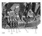
- FIG. 2 is a perspective view of an exemplary embodiment of a system 2000 , which can comprise a plurality of circuit breaker components.
- System 2000 can comprise an electrical source contact 2100 , which can be operatively coupled to a source of electrical energy.
- System 2000 can comprise a load side contact arm 2600 , which can be adapted to, when in contact with electrical source contact 2100 , transfer electrical energy to a load side of a circuit breaker that comprises system 2000 .
- Load side contact arm 2600 can be adapted to retract to the position illustrated in system 2000 responsive to a short circuit event on a load side and/or supply side of the circuit breaker that comprises system 2000 .
- System 2000 can comprise a plurality of arc plates and/or arc plate configurations, such as arc plate 2200 , arc plate 2300 , and/or arc plate 2400 .
- Arc plate configurations such as arc plate 2200 , arc plate 2300 , and/or arc plate 2400 , can be a component of a primary shunt, within the circuit breaker adapted for transferring and/or dissipating electrical energy during a short circuit event.
- load side contact arm 2600 can begin to move from a state of being in contact with electrical source contact 2100 .
- an arc can form between load side contact arm 2600 and electrical source contact 2100 , which can damage surfaces of load side contact arm 2600 and/or electrical source contact 2100 .
- arc plate 2200 is in relatively close proximity to electrical source contact 2100 , as contact arm 2600 retracts, when a sufficient electrical potential difference exists between electrical source contact 2100 and load side contact arm 2600 , an arc can form between electrical source contact 2100 and arc plate 2200 .
- the arc formed between electrical source contact 2100 and arc plate 2200 can limit damage to contact surfaces of load side contact arm 2600 and/or electrical source contact 2100 .
- an arc can develop between arc plate 2200 and arc plate 2300 . If the potential difference is sufficiently high, an arc can develop between arc plate 2300 and arc plate 2400 , which under certain levels of electrical potential can result in arcing between arc plate 2400 and electrical bypass conductor 2500 .
- Electrical bypass conductor 2500 can be electrically coupled and/or fastenerlessly attached to a lug 2700 , which can be located on a load side of the circuit breaker and/or electrically coupled to an electrical load. Electrical energy from the short circuit event can be, at least partially, routed to the electrical load via arc plate 2200 , arc plate 2300 , arc plate 2400 , electrical bypass conductor 2500 , and lug 2700 . Electrical bypass conductor 2500 can be a fastenerless electrical bypass conductor 2500 adapted for installation in the circuit breaker. Electrical bypass conductor 2500 can comprise a fork that can define a first prong and/or a second prong.
- the first prong and the second prong can be adapted to allow passage of contact arm 2600 therebetween.
- the fork can be similarly shaped to at least one arc plate configuration (such as arc plate 2200 , arc plate 2300 , and/or arc plate 2400 ).
- Electrical bypass conductor 1500 can be adapted to be operatively electrically coupled to a load side of the circuit breaker.
- Electrical bypass conductor 2500 can be adapted to transfer electrical energy from a source of electrical power, via at least one arc plate configuration (such as arc plate 2200 , arc plate 2300 , and/or arc plate 2400 ), to the load side of the circuit breaker during the short circuit event.
- FIG. 3 is a perspective view of an exemplary embodiment of a system 3000 , which can represent a partial cross sectional view of a portion of a circuit breaker.
- System 3000 can comprise an electrical bypass conductor 3100 , which can comprise a first end 3200 and a second end 3300 .
- First end 3200 can define a two-tined fork comprising a first prong and a second prong.
- Components comprised in system 3000 can be integral to and/or separate from a housing structure comprising system 3000 .
- portions of system 3000 such as a retainer surface 3400 , retainer surface 3500 , and retainer surface 3600 can be non-integral to a housing of the circuit breaker and can be fixedly and/or releasably attached thereto.
- Electrical bypass conductor 3100 can be fastenerless, and/or can be adapted to be releasably, springably, biasedly, and/or fastenerlessly seated between at least two surfaces, such as retainer surface 3400 , retainer surface 3500 , and/or retainer surface 3600 , of circuit breaker case 3050 .
- Electrical bypass conductor 3100 can be adapted to be releasably seated in circuit breaker case 3050 .
- Electrical bypass conductor 3100 can be adapted to contact at least one of retainer surface 3400 , retainer surface 3500 and retainer surface 3600 defined by circuit breaker case 3050 .
- Electrical bypass conductor 3100 can be adapted to be installed, secured, and/or retained in circuit breaker case 3050 via tension, bias, and/or releasable and/or elastic deformation. Electrical bypass conductor 3100 can be adapted to be nondestructively removed from circuit breaker case 3050 , such as substantially without utilizing a tool, and/or via a gripping tool such as needle-nosed pliers.
- the two-tined fork of first end 3200 can be adapted to allow passage of a contact arm 3800 between the first prong and the second prong.
- Second end 3300 can be adapted to be electrically coupled to a load side lug 3700 .
- the electrical coupling of load side lug 3700 and second end 3300 can result from a biased fit of electrical bypass conductor 3100 between retainer surface 3600 and load side lug 3700 .
- a retainer surface 3600 can act as a fulcrum adapted to urge a bend in electrical bypass conductor 3100 in order to provide a biased electrically conductive contact between second end 3300 of electrical bypass conductor 3100 and lug 3700 .
- Motion of electrical bypass conductor 3100 can be constrained by a fit of electrical bypass conductor 3100 between retainer surface 3400 and retainer surface 3500 .
- a portion of electrical bypass conductor 3100 can rest on retainer surface 3500 of circuit breaker case 3050 .
- FIG. 4 is a perspective view of an exemplary embodiment of an electrical bypass conductor 4000 , which can comprise a fork 4100 that can define a first prong 4100 and/or a second prong 4200 .
- FIG. 5 is a flowchart of an exemplary embodiment of a method 5000 .
- a circuit breaker can be obtained.
- arc plates and/or arc plate configurations adapted to be operatively installed in the circuit breaker, can be obtained.
- an electrical bypass conductor can be obtained.
- the arc plates can be installed in the circuit breaker. Note that, in certain embodiments, this activity can occur prior to activity 5300 .
- the electrical bypass conductor can be installed in the circuit breaker.
- the electrical bypass conductor can be adapted to be fastenerlessly installed in the circuit breaker and/or releasably attached to the circuit breaker without being heatedly fused and/or installed via a fastener to one or more components comprised by the circuit breaker.
- the lug end portion of the electrical bypass conductor can be slid between a lug surface and a retaining surface, then the lug end portion can be flexed sufficiently to allow a central portion of the electrical bypass conductor to be slid between two or more retaining surfaces, which can allow an arc end portion of the electrical bypass conductor to slide into position substantially adjacent an arc plate region of the circuit breaker.
- the electrical bypass conductor can comprise a fork that can define a first prong and/or a second prong.
- the first prong and/or the second prong can be adapted to allow passage of a contact arm of the circuit breaker therebetween.
- the electrical bypass conductor can be adapted to be operatively electrically coupled to a load side of the circuit breaker.
- the electrical bypass conductor can be adapted to transfer electrical energy from a source of electrical power, via at least one arc plate configuration, to the load side of the circuit breaker during a short circuit event.
- the electrical bypass conductor can be adapted to substantially electrically bypass at least one component of the circuit breaker during the short circuit event.
- the contact arm of the circuit breaker in an operative embodiment, can be adapted to pass between the first prong and the second prong of the electrical bypass conductor during the short circuit event.
- a shunt and/or electrically conductive path can be formed via which current can flow through and/or across the electrical source contact, one or more arc plates, the arc end portion of the electrical bypass conductor, the lug end portion of the electrical bypass conductor, and/or to a load side lug of the circuit breaker, etc.
- the shunt can be adapted to transfer electrical energy to the load side of the circuit breaker during the short circuit event.
- the electrical bypass conductor can comprise a lug end portion adapted to be operatively electrically coupled and/or fastenerlessly attached to the lug of the load side of the circuit breaker.
- electrical energy can be operatively connected to the circuit breaker.
- a circuit breaker can be tripped due to a short circuit condition.
- electrical energy associated with the short circuit can be transferred to the load side lug of the circuit breaker via the electrical bypass conductor and/or one or more arc plates and/or arc plate configurations.
- the electrical bypass conductor and/or the arc plates and/or arc plate configurations can be adapted to attempt to reduce wear and/or damage to contact surfaces of the contact arm and/or an electrical source contact.
Abstract
Description
-
- a—at least one.
- activity—an action, act, deed, function, step, and/or process and/or a portion thereof.
- adapted for—suitable, fit, and/or capable of performing a specified function.
- adapted to—suitable, fit, and/or capable of performing a specified function.
- adapter—a device used to effect operative compatibility between different parts of one or more pieces of an apparatus or system.
- allow—to provide, let do, happen, and/or permit.
- and/or—either in conjunction with or in alternative to.
- apparatus—an appliance or device for a particular purpose
- arc plate configuration—an electrically conductive substantially rigid and/or substantially planar body adapted to act a primary shunt for a circuit breaker when contacts of the circuit breaker open.
- associate—to relate, bring together in a relationship, map, combine, join, and/or connect.
- at least—not less than.
- attach—to fasten, secure, couple, and/or join.
- between—in a separating interval and/or intermediate to.
- bias—n. a tension and/or force; v. to urge and/or force.
- by—with the use of.
- bypass—to avoid by using an alternative.
- can—is capable of, in at least some embodiments.
- case—a container adapted to substantially enclose a circuit breaker, the case comprises integral and/or separable components adapted to fasten, retain, and/or support electrical components comprised by the circuit breaker.
- cause—to bring about, provoke, precipitate, produce, elicit, be the reason for, result in, and/or effect.
- circuit breaker—a re-settable device adapted to automatically open an alternating current electrical circuit to protect the circuit from damage caused by overload and/or short circuit.
- component—a constituent element and/or part.
- comprising—including but not limited to, what follows.
- configure—to design, arrange, set up, shape, and/or make suitable and/or fit for a specific purpose.
- connect—physically or logically join, link, couple, and/or fasten two or more entities.
- connective portion—a part of a device adapted to electrically couple the device to an electrical circuit.
- contact arm—a member comprising one of a pair of electrical contacts engageable to close a circuit.
- convert—to transform, adapt, and/or change, such as from a first form to a second form.
- couple—to join, connect, and/or link two things together.
- coupleable—capable of being joined, connected, and/or linked together.
- create—to make, form, produce, generate, bring into being, and/or cause to exist.
- define—to establish the meaning, relationship, outline, form, and/or structure of; and/or to precisely and/or distinctly describe and/or specify.
- determine—to obtain, calculate, decide, deduce, establish, and/or ascertain.
- device—an instrumentality adapted to a particular purpose.
- during—at some time in a time interval.
- electrical—relating to producing, distributing, and/or operating by electricity.
- electrical energy—energy characterized by, and/or adapted to cause, a flow of electric charge through a conductor.
- electrically couple—to connect in a manner adapted to allow a flow of electricity therebetween.
- event—an occurrence.
- fasten—to attach to something else and/or to hold something in place.
- fastener—a distinct restraint that attaches two or more things. A fastener can be a screw, bolt, hook and/or loop of a hook and loop fastener system, button, hook, catch, snap, latch, buckle, loop, tie, clamp, connector, coupler, link, band, zipper, releasable adhesive, plug and socket, and/or any other releasable means for attachment, and/or a glue, bond, weld, and/or any other permanent means for attachment
- fastenerless—adapted to be positioned and/or retained at a predetermined location and/or adapted to limit motion and/or rotation in one or more predetermined directions without utilizing a fastener. Examples can include tongue and groove joints, wedges, and/or a self-biased interaction between a first part and a second part, etc.
- fastenerless electrical bypass conductor—a device, adapted to be installed in a circuit breaker without a fastener, adapted to divert a flow of electrical energy to a load side of a circuit breaker responsive to an opening of contacts of the circuit breaker during a short circuit event.
- first—being before all others in an ordering.
- for—with a purpose of.
- fork—a device having two or more prongs.
- form—to make, construct, and/or produce.
- from—used to indicate a source.
- further—in addition.
- fuse—to melt together.
- generate—to create, produce, render, give rise to, and/or bring into existence.
- heat—energy associated with the motion of atoms and/or molecules and capable of being transmitted through solid and fluid media by conduction, through fluid media by convection, and through a fluid and/or empty space by radiation.
- heatedly—via thermal energy.
- initialize—to create, produce, render, give rise to, and/or bring into existence.
- install—to set in position and/or prepare for use.
- installation—a state of being installed.
- load side—a portion of an electric circuit breaker that is electrically coupled to at least one electricity utilizing device.
- lug—an electrical terminal adapted to be electrically coupled to a conductor, the conductor electrically couplable to an electrical energy source.
- may—is allowed and/or permitted to, in at least some embodiments.
- method—a process, procedure, and/or collection of related activities for accomplishing something.
- method—a process, procedure, and/or collection of related activities for accomplishing something.
- more—greater.
- nondestructively—to perform substantially without damaging.
- occur—to take place.
- one—a singular unit.
- operative—being in effect; operating.
- pass—to move relative to an object.
- passage—a motion of a first object relative to a second object.
- plurality—the state of being plural and/or more than one.
- plurality—the state of being plural and/or more than one.
- power—energy, a measure of energy and/or work, and/or a rate at which work is done, expressed as the amount of work per unit time and commonly measured in units such as watt and horsepower.
- predetermined—established in advance.
- primary—first in an ordering.
- prong—a projecting part, such as a protrusion, bar, stub, rod, pin, cylinder, etc.
- protect—to attempt to prevent and/or avoid damage.
- provide—to furnish or supply.
- receive—to gather, take, acquire, obtain, accept, get, and/or have bestowed upon.
- releasably—capable of being freed, in a substantially non-destructive manner, from something that binds, fastens, or holds back.
- remove—to eliminate, remove, and/or delete, and/or to move from a place or position occupied.
- rest—to not move and/or be supported by.
- said—when used in a system or device claim, an article indicating a subsequent claim term that has been previously introduced.
- seat—to attach to or place firmly in or on something.
- second—being immediately after a first item in an exemplary ordering.
- secondary—second in an ordering.
- shape—a characteristic surface, outline, and/or contour of an entity.
- short circuit—an abnormal condition of relatively low resistance between two points of different potential in a circuit resulting in an excess flow of current relative to the range of currents typically conducted via the circuit.
- shunt—a device adapted to divert a flow of electrical current.
- similar—having a resemblance.
- source—an original and/or intermediate transmitter of traffic and/or a related group of such transmitters and/or a point at which something originates, springs into being, and/or from which it derives and/or is obtained.
- springably—elastically movable from a first position to a second position.
- substantially—to a considerable, large, and/or great, but not necessarily whole and/or entire, extent and/or degree.
- support—to bear the weight of, especially from below.
- surface—the outer boundary of an object or a material layer constituting or resembling such a boundary.
- system—a collection of mechanisms, devices, data, and/or instructions, the collection designed to perform one or more specific functions.
- tension—a deformation of an at least partially elastic body.
- that—used as the subject or object of a relative clause.
- therebetween—in an interval separating a first thing from a second thing.
- therethrough—in one end and out another end of an object.
- tool—something used to accomplish a task.
- transfer—(n) a transmission from one device, place, and/or state to another. (v) to convey from one device, place, and/or state to another.
- two—a cardinal number equal to one plus one.
- via—by way of and/or utilizing.
- weight—a force with which a body is attracted to Earth or another celestial body, equal to the product of the object's mass and the acceleration of gravity.
- wherein—in regard to which; and; and/or in addition to.
- within—inside.
- without—not accompanied by.
Note
-
- there is no requirement for the inclusion of any particular described or illustrated characteristic, function, activity, or element, any particular sequence of activities, or any particular interrelationship of elements;
- any elements can be integrated, segregated, and/or duplicated;
- any activity can be repeated, performed by multiple entities, and/or performed in multiple jurisdictions; and
- any activity or element can be specifically excluded, the sequence of activities can vary, and/or the interrelationship of elements can vary.
Claims (20)
Priority Applications (5)
| Application Number | Priority Date | Filing Date | Title |
|---|---|---|---|
| US11/796,195 US7796369B2 (en) | 2006-05-01 | 2007-04-27 | Devices, systems, and methods for shunting a circuit breaker |
| CA2650854A CA2650854C (en) | 2006-05-01 | 2007-04-30 | Devices, systems, and methods for shunting a circuit breaker |
| PCT/US2007/010384 WO2007130321A1 (en) | 2006-05-01 | 2007-04-30 | Devices, systems, and methods for shunting a circuit breaker |
| CN200780015736.4A CN101432836B (en) | 2006-05-01 | 2007-04-30 | Devices, systems, and methods for shunting a circuit breaker |
| EP07776453.8A EP2013890B1 (en) | 2006-05-01 | 2007-04-30 | System and method for shunting a circuit breaker |
Applications Claiming Priority (2)
| Application Number | Priority Date | Filing Date | Title |
|---|---|---|---|
| US74610406P | 2006-05-01 | 2006-05-01 | |
| US11/796,195 US7796369B2 (en) | 2006-05-01 | 2007-04-27 | Devices, systems, and methods for shunting a circuit breaker |
Publications (2)
| Publication Number | Publication Date |
|---|---|
| US20070253130A1 US20070253130A1 (en) | 2007-11-01 |
| US7796369B2 true US7796369B2 (en) | 2010-09-14 |
Family
ID=38648058
Family Applications (1)
| Application Number | Title | Priority Date | Filing Date |
|---|---|---|---|
| US11/796,195 Active 2029-06-17 US7796369B2 (en) | 2006-05-01 | 2007-04-27 | Devices, systems, and methods for shunting a circuit breaker |
Country Status (5)
| Country | Link |
|---|---|
| US (1) | US7796369B2 (en) |
| EP (1) | EP2013890B1 (en) |
| CN (1) | CN101432836B (en) |
| CA (1) | CA2650854C (en) |
| WO (1) | WO2007130321A1 (en) |
Citations (15)
| Publication number | Priority date | Publication date | Assignee | Title |
|---|---|---|---|---|
| US2134565A (en) | 1936-10-09 | 1938-10-25 | Westinghouse Electric & Mfg Co | Circuit breaker |
| US3040144A (en) | 1959-07-16 | 1962-06-19 | Fed Pacific Electric Co | Circuit breakers |
| FR2344949A1 (en) | 1976-03-15 | 1977-10-14 | Merlin Gerin | Low voltage miniature contact breaker for domestic use - has bimetal strips and solenoid for release and laminated stack for arc blowout |
| US4516003A (en) * | 1982-06-15 | 1985-05-07 | Mitsubishi Denki Kabushiki Kaisha | Circuit breaker with arc light absorber |
| DE3619240A1 (en) | 1986-06-07 | 1987-12-10 | Kloeckner Moeller Elektrizit | Line protection circuit breaker having a contact arrangement which forms a blowing device |
| EP0255992A2 (en) | 1986-08-04 | 1988-02-17 | BASSANI TICINO S.p.A. | A double-pole circuit breaker for civil range electric equipment, incorporating an arc change-over device |
| US5164693A (en) * | 1988-06-09 | 1992-11-17 | Electric Power Research Institute, Inc. | Remotely controllable circuit breaker with improved arc drive structure |
| US5196815A (en) | 1992-01-31 | 1993-03-23 | Westinghouse Electric Corp. | Miniature circuit breaker |
| WO1995019631A1 (en) | 1994-01-13 | 1995-07-20 | Square D Company | Blade transfer runner and arc shunt for a double break circuit breaker |
| US5859578A (en) | 1997-03-04 | 1999-01-12 | General Electric Company | Current limiting shunt for current limiting circuit breakers |
| US6084188A (en) * | 1999-08-18 | 2000-07-04 | Eaton Corporation | Circuit interrupter with non-symmetrical terminal collar |
| US6248970B1 (en) * | 1999-11-05 | 2001-06-19 | Siemens Energy & Automation, Inc. | ARC chute for a molded case circuit breaker |
| US6300586B1 (en) * | 1999-12-09 | 2001-10-09 | General Electric Company | Arc runner retaining feature |
| WO2002031849A1 (en) | 2000-10-12 | 2002-04-18 | Eaton Corporation | Circuit breaker with bypass for redirecting high transient current and associated method |
| US20020075123A1 (en) | 2000-12-18 | 2002-06-20 | Lias Edward Ethber | Circuit breaker with bypass conductor commutating current out of the bimetal during short circuit interruption and method of commutating current out of bimetal |
Family Cites Families (3)
| Publication number | Priority date | Publication date | Assignee | Title |
|---|---|---|---|---|
| JPS60117546U (en) * | 1984-01-17 | 1985-08-08 | 三菱電機株式会社 | electromagnetic contactor |
| DE9206136U1 (en) * | 1992-05-07 | 1993-09-09 | Siemens Ag | Electrical switching device with arc guide parts |
| FR2795858B1 (en) * | 1999-07-01 | 2001-09-14 | Schneider Electric Ind Sa | ELECTRICAL SWITCHING APPARATUS HAVING A CONTACT MEMBER PROVIDED WITH A SPARK BARRIER |
-
2007
- 2007-04-27 US US11/796,195 patent/US7796369B2/en active Active
- 2007-04-30 EP EP07776453.8A patent/EP2013890B1/en not_active Not-in-force
- 2007-04-30 CA CA2650854A patent/CA2650854C/en active Active
- 2007-04-30 WO PCT/US2007/010384 patent/WO2007130321A1/en active Application Filing
- 2007-04-30 CN CN200780015736.4A patent/CN101432836B/en active Active
Patent Citations (15)
| Publication number | Priority date | Publication date | Assignee | Title |
|---|---|---|---|---|
| US2134565A (en) | 1936-10-09 | 1938-10-25 | Westinghouse Electric & Mfg Co | Circuit breaker |
| US3040144A (en) | 1959-07-16 | 1962-06-19 | Fed Pacific Electric Co | Circuit breakers |
| FR2344949A1 (en) | 1976-03-15 | 1977-10-14 | Merlin Gerin | Low voltage miniature contact breaker for domestic use - has bimetal strips and solenoid for release and laminated stack for arc blowout |
| US4516003A (en) * | 1982-06-15 | 1985-05-07 | Mitsubishi Denki Kabushiki Kaisha | Circuit breaker with arc light absorber |
| DE3619240A1 (en) | 1986-06-07 | 1987-12-10 | Kloeckner Moeller Elektrizit | Line protection circuit breaker having a contact arrangement which forms a blowing device |
| EP0255992A2 (en) | 1986-08-04 | 1988-02-17 | BASSANI TICINO S.p.A. | A double-pole circuit breaker for civil range electric equipment, incorporating an arc change-over device |
| US5164693A (en) * | 1988-06-09 | 1992-11-17 | Electric Power Research Institute, Inc. | Remotely controllable circuit breaker with improved arc drive structure |
| US5196815A (en) | 1992-01-31 | 1993-03-23 | Westinghouse Electric Corp. | Miniature circuit breaker |
| WO1995019631A1 (en) | 1994-01-13 | 1995-07-20 | Square D Company | Blade transfer runner and arc shunt for a double break circuit breaker |
| US5859578A (en) | 1997-03-04 | 1999-01-12 | General Electric Company | Current limiting shunt for current limiting circuit breakers |
| US6084188A (en) * | 1999-08-18 | 2000-07-04 | Eaton Corporation | Circuit interrupter with non-symmetrical terminal collar |
| US6248970B1 (en) * | 1999-11-05 | 2001-06-19 | Siemens Energy & Automation, Inc. | ARC chute for a molded case circuit breaker |
| US6300586B1 (en) * | 1999-12-09 | 2001-10-09 | General Electric Company | Arc runner retaining feature |
| WO2002031849A1 (en) | 2000-10-12 | 2002-04-18 | Eaton Corporation | Circuit breaker with bypass for redirecting high transient current and associated method |
| US20020075123A1 (en) | 2000-12-18 | 2002-06-20 | Lias Edward Ethber | Circuit breaker with bypass conductor commutating current out of the bimetal during short circuit interruption and method of commutating current out of bimetal |
Also Published As
| Publication number | Publication date |
|---|---|
| WO2007130321A1 (en) | 2007-11-15 |
| CA2650854C (en) | 2014-12-02 |
| CN101432836B (en) | 2012-12-26 |
| EP2013890A1 (en) | 2009-01-14 |
| CN101432836A (en) | 2009-05-13 |
| CA2650854A1 (en) | 2007-11-15 |
| US20070253130A1 (en) | 2007-11-01 |
| EP2013890B1 (en) | 2016-08-17 |
| WO2007130321A8 (en) | 2008-11-06 |
Similar Documents
| Publication | Publication Date | Title |
|---|---|---|
| US7656640B2 (en) | Voltage surge protection device | |
| CA2781263C (en) | Disconnect switch including fusible switching disconnect modules | |
| KR100922694B1 (en) | Arc-less electrical connector | |
| CN102024542B (en) | Overvoltage protection element | |
| EP1782447B1 (en) | Systems, methods, and device for actuating a circuit breaker | |
| CZ247295A3 (en) | Protective coupler plug | |
| US7843291B2 (en) | Integrated maglatch accessory | |
| CN110086144A (en) | Protective device | |
| CN105580092A (en) | Compact pre-assemblable overvoltage protection device | |
| US8754727B2 (en) | Devices, systems, and methods for shunting a circuit breaker | |
| US9865415B2 (en) | Two piece handle for miniature circuit breakers | |
| US6274833B1 (en) | Plug-in trip unit joint for a molded case circuit breaker | |
| US7796369B2 (en) | Devices, systems, and methods for shunting a circuit breaker | |
| US6617533B1 (en) | Interlock for a circuit breaker | |
| KR101072976B1 (en) | Leakage breaker for preventing from flowing high current | |
| US5430420A (en) | Contact arrangement for a circuit breaker using magnetic attraction for high current trip | |
| US6448876B1 (en) | Load terminal with conductive tang for use in a circuit breaker | |
| US4771254A (en) | Circuit breaker magnetic trip unit | |
| MX2008013962A (en) | Devices, systems, and methods for shunting a circuit breaker. | |
| CN202058668U (en) | Selective circuit protection switch | |
| CN103632893A (en) | Electrical contact position indicator apparatus, systems and methods of operation | |
| US2863964A (en) | Automatic circuit breakers | |
| JPS59209237A (en) | Current limiting device of circuit breaker |
Legal Events
| Date | Code | Title | Description |
|---|---|---|---|
| AS | Assignment |
Owner name: SIEMENS ENERGY & AUTOMATION, INC., GEORGIA Free format text: ASSIGNMENT OF ASSIGNORS INTEREST;ASSIGNORS:MCCOY, BRIAN TIMOTHY;HOLLAND, THOMAS WILLIAM;REEL/FRAME:021678/0893 Effective date: 20081006 |
|
| AS | Assignment |
Owner name: SIEMENS INDUSTRY, INC.,GEORGIA Free format text: MERGER;ASSIGNORS:SIEMENS ENERGY AND AUTOMATION;SIEMENS BUILDING TECHNOLOGIES, INC.;REEL/FRAME:024427/0113 Effective date: 20090923 Owner name: SIEMENS INDUSTRY, INC., GEORGIA Free format text: MERGER;ASSIGNORS:SIEMENS ENERGY AND AUTOMATION;SIEMENS BUILDING TECHNOLOGIES, INC.;REEL/FRAME:024427/0113 Effective date: 20090923 |
|
| STCF | Information on status: patent grant |
Free format text: PATENTED CASE |
|
| FPAY | Fee payment |
Year of fee payment: 4 |
|
| MAFP | Maintenance fee payment |
Free format text: PAYMENT OF MAINTENANCE FEE, 8TH YEAR, LARGE ENTITY (ORIGINAL EVENT CODE: M1552) Year of fee payment: 8 |
|
| MAFP | Maintenance fee payment |
Free format text: PAYMENT OF MAINTENANCE FEE, 12TH YEAR, LARGE ENTITY (ORIGINAL EVENT CODE: M1553); ENTITY STATUS OF PATENT OWNER: LARGE ENTITY Year of fee payment: 12 |