US7796193B2 - Method of adaptive slicing signal - Google Patents
Method of adaptive slicing signal Download PDFInfo
- Publication number
- US7796193B2 US7796193B2 US11/427,390 US42739006A US7796193B2 US 7796193 B2 US7796193 B2 US 7796193B2 US 42739006 A US42739006 A US 42739006A US 7796193 B2 US7796193 B2 US 7796193B2
- Authority
- US
- United States
- Prior art keywords
- signal
- slicing
- values
- video signal
- local maximum
- Prior art date
- Legal status (The legal status is an assumption and is not a legal conclusion. Google has not performed a legal analysis and makes no representation as to the accuracy of the status listed.)
- Expired - Fee Related, expires
Links
Images


Classifications
-
- H—ELECTRICITY
- H04—ELECTRIC COMMUNICATION TECHNIQUE
- H04N—PICTORIAL COMMUNICATION, e.g. TELEVISION
- H04N7/00—Television systems
- H04N7/025—Systems for the transmission of digital non-picture data, e.g. of text during the active part of a television frame
- H04N7/035—Circuits for the digital non-picture data signal, e.g. for slicing of the data signal, for regeneration of the data-clock signal, for error detection or correction of the data signal
- H04N7/0355—Circuits for the digital non-picture data signal, e.g. for slicing of the data signal, for regeneration of the data-clock signal, for error detection or correction of the data signal for discrimination of the binary level of the digital data, e.g. amplitude slicers
Definitions
- the present invention relates to a slicing signal generator, and more particularly to a slicing signal generator providing an adaptive slicing signal.
- Teletext carried by a TV/video signal at a VBI has been popularly used in TV broadcasts to provide real-time information such as weather, advertising, movie and flight schedules.
- a slicing signal is applied to decode the teletext data carried by the TV/video signal.
- the slicing signal provides a slicing level to be compared with the TV/video signal.
- the data carried by the TV/video signal is determined as logic 1
- the data carried by the TV/video signal is determined as logic 0.
- FIG. 1 illustrates a waveform and corresponding slicing result of a TV signal.
- the VBI can be divided into clock-run-in, start code (not shown in FIG. 1 ), and teletext data.
- the slicing level is typically determined by the signal amplitude during the clock-run-in interval, for example, the slicing level is the average amplitude of the TV signal received during clock-run-in interval.
- FIG. 2 is a block diagram of a slicing signal generator.
- the clock-run-in window generates an enable signal to turn on the gate 21 for the clock-run-in interval. When the gate 21 is turned on, the TV signal is passed to an average computer unit 22 to compute a slicing signal.
- FIG. 3 is a waveform of a TV signal with noise.
- the DC (direct current) component of the TV signal varies significantly while delivering the actual teletex data, thus the slicing signal derived from the clock-run-in interval is inappropriate.
- a slicing signal generator generates an adaptive slicing signal for a TV/video signal, and a decoding system with the slicing signal generator decodes the TV/video signal.
- a slicing signal generator for a video signal comprises an extreme value detector, a first filter, a second filter and a computing unit.
- the extreme value detector determines a plurality of local maximum and local minimum values of the video signal.
- the first filter generates a local maximum envelope based on the local maximum values.
- the second filter generates a local minimum envelope based on the local minimum values.
- the computing unit generates a slicing signal based on the local maximum envelope and the local minimum envelope.
- a slicing signal generator for a video signal comprises an extreme value detector, a computing unit and a filter.
- the extreme value detector determines a plurality of local maximum values and local minimum values of the video signal.
- the computing unit generates a plurality of weighted values based on the corresponding local maximum values and the corresponding local minimum values.
- the filter generates a slicing signal based on the weighted values.
- a slicing signal generator for a video signal comprises an extreme value detector, a NOR gate, a switch unit, a median computing unit and a filter.
- the extreme value detector generates a first valid signal and a second valid signal, wherein when a local maximum value is determined, the first valid signal is at a logic high level and when a local minimum value is determined, the second valid signal is at a logic high level.
- the NOR gate receives the first valid signal and the second valid signal to generate an enable signal.
- the switch unit is turned on when the enable signal is at the logic high level.
- the median computing unit coupled to the switch generates a plurality of median values of the data signal except for the local maximum values and the local minimum values.
- the filter generates a slicing signal based on the median values.
- a video signal decoding system for a TV signal comprises a synchronous separator, a line counter, a slicing signal generator and a comparator.
- the synchronous separator detects Hsync and Vsync in the video signal.
- the line counter counts the number of scanning lines of the TV signal according to the Hsync and Vsync, and when the count number reaches a predetermined value, the video signal decoding system receives TV signal carrying teletext information, thus, the line counter generates an enable signal.
- the slicing signal generator generates a slicing signal for the TV signal, where the slicing signal is adaptable to the TV signal.
- the comparator enabled by the enable signal compares the TV signal with the slicing signal, and outputs teletext data.
- a method for slicing data carried on a data signal of a video signal comprises separating Hsync and Vsync from the video signal, determining local maximum values and local minimum values of the data signal, generating a slicing signal based on the local maximum values and the local minimum values, generating an enable signal that is active when the video signal carrying teletext and/or other binary data, when the enable signal is active, comparing the video signal with the slicing signal.
- FIG. 1 illustrates a waveform and a slicing result of a TV signal.
- FIG. 2 is a block diagram of a conventional slicing signal generator.
- FIG. 3 shows a waveform of a TV signal with noise.
- FIG. 4 is a block diagram of an embodiment of a slicing signal generator.
- FIG. 5 is a block diagram of an embodiment of a local maximum value detector.
- FIG. 6 is a block diagram of an embodiment of a local minimum value detector.
- FIG. 7 is a block diagram of another embodiment of the slicing signal generator.
- FIG. 8 is a block diagram of an embodiment of the extreme value detector.
- FIG. 9 is a block diagram of another embodiment of the slicing signal generator.
- FIG. 10 is a block diagram of an embodiment of the video signal decoding system.
- FIG. 11 is a block diagram of the video signal decoding system of FIG. 10 with a low pass filter.
- FIG. 12 is a block diagram of the video signal decoding system of FIG. 10 with a switch unit.
- FIG. 4 is a block diagram of an embodiment of a slicing signal generator.
- the slicing signal generator 40 comprises an extreme value detector 41 , a filter module 42 and a computing unit 47 .
- the extreme value detector 41 determines a plurality of local maximum and local minimum values of the TV signal.
- the extreme value detector 41 comprises a local maximum value detector 43 and a local minimum value detector 44 respectively determining the local maximum values and the local minimum values.
- Filter module 42 receives the local maximum values and the local minimum values to generate a local maximum envelope and a local minimum envelope.
- the filter module 42 comprises a first filter 45 coupled to the local maximum value detector 43 and a second filter 46 coupled to the local minimum value detector 44 .
- the FIR (Finite Impulse Response) filter and the IIR (Infinite Impulse Response) filter are exemplary embodiments of the first filter 45 and the second filter 46 .
- a purpose of the filters 45 and 46 is to filter out outliers to improve the noise robustness of the input of the computing unit 47 .
- the computing unit 47 generates the slicing signal based on the received local maximum envelope and local minimum envelope.
- the slicing signal is the average of the local maximum envelope and the local minimum envelope.
- the slicing signal is a weighted average of the local maximum envelope and the local minimum envelope.
- the slicing signal is adaptable to the TV signal, so that the sliced data may achieves error robustness to rapid shift in DC level of the TV signal as shown in FIG. 3 .
- FIG. 5 is a block diagram of an embodiment of a local maximum value detector.
- Local maximum value detector 50 comprises a first register 51 , a second register 52 , a third register 53 , a subtractor 54 , a first comparator 55 , a second comparator 56 and a AND gate 57 .
- the first register 51 stores the (n+2)th data of the data signal, X[n+2].
- the second register 52 stores the (n+1)th data of the data signal, X[n+1].
- the third register 53 stores the nth data of the data signal, X[n].
- X[n+1] exceeds X[n+2] and X[n] with a predetermined value
- M X[n+1] is determined to be a local maximum value.
- a subtractor 54 is applied to generate the difference Y 1 between the M and X[n+1].
- the first comparator 55 compares Y 1 with X[n+2] to generate a first signal, wherein when Y 1 exceeds X[n+2], the first signal is at logic high level.
- the second comparator 56 compares Y 1 with X[n] to generate a second signal, wherein when Y 1 exceeds X[n], the second signal is at logic high level.
- the AND gate 57 receives the first signal and the second signal to generate a first valid signal.
- X[n+1] is determined as a local maximum value and transmitted to the filter, such as the filter module 42 or the first filter 45 .
- FIG. 6 is a block diagram of an embodiment of a local minimum value detector.
- Local maximum value detector 60 comprises a first register 61 , a second register 62 , a third register 63 , an adder 64 , a third comparator 65 , a fourth comparator 66 and an AND gate 67 .
- the first register 61 stores the (n+2)th data of the data signal, X[n+2].
- the second register 62 stores the (n+1)th data of the data signal, X[n+1].
- the third register 63 stores the nth data of the data signal, X[n].
- X[n+1] when X[n+2] exceeds X[n+1] with a predetermined value, M, and X[n] exceeds X[n+1] with a predetermined value, M, X[n+1] is determined as a local minimum value.
- an subtractor 54 is applied to generate the sum Y 2 of X[n+1] and M.
- the third comparator 65 compares X[n+2] with Y 2 to generate a third signal, wherein when X[n+2] exceeds Y 2 , the third signal is at logic high level.
- the fourth comparator 66 compares X[n] with Y 2 to generate a fourth signal, wherein when X[n] exceeds Y 2 , the fourth signal is at logic high level.
- the AND gate 67 receives the third signal and the fourth signal to generate a second valid signal.
- X[n+1] is determined as a local minimum value and transmitted to the filter, such as the filter module 42 or the second filter 46 .
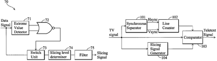
- FIG. 7 is a block diagram of another embodiment of the slicing signal generator.
- the slicing signal generator 70 comprises an extreme value detector 71 , a NOR gate 72 , a switch unit 73 , a slicing level determiner 74 and a filter 75 .
- FIR Finite Impulse Response
- IIR Infinite Impulse Response
- the extreme value detector 71 generates a first valid signal and a second valid signal according to the data signal. When a local maximum value or a local minimum value is determined, the first valid signal or the second valid signal is at logic high level, thus, an enable signal generated by the NOR gate 72 is active.
- the switch unit 73 When the enable signal is at logic low level, the switch unit 73 turns off, thus, the slicing level determiner cannot receive the data signal.
- the slicing level determiner 74 filters out local maximum values and local minimum values, and generates and transmits medians of the remaining data signal to the filter 75 .
- the slicing level determiner 74 reserves only the local maximum values and the local minimum values, and generates and transmits weighted values of the local maximum values and the local minimum values to the filter 75 . Then, the filter 75 generates the slicing signal according to the data from the slicing level determiner 74 .
- FIG. 8 is a block diagram of an embodiment of the extreme value detector.
- the extreme value detector 80 comprises a first register 81 , a second register 82 , a third register 83 , a subtractor 88 a , an adder 88 b , a first comparator 84 , a second comparator 85 , a third comparator 86 , a fourth comparator 87 , a first AND gate 89 a and a second AND gate 89 b .
- the first register 81 stores the (n+2)th data of the data signal, X[n+2].
- the second register 82 stores the (n+1)th data of the data signal, X[n+1].
- the third register 83 stores the nth data of the data signal, X[n].
- X[n+1] exceeds X[n+2] and X[n] with a predetermined value
- M X[n+1] is determined to be a local maximum value.
- a subtractor 88 a is applied to generate the difference Y 1 between the M and X[n+1].
- the first comparator 84 compares Y 1 with X[n+2] to generate a first signal, wherein when Y 1 exceeds X[n+2], the first signal is at logic high level.
- the second comparator 85 compares Y 1 with X[n] to generate a second signal, wherein when Y 1 exceeds X[n], the second signal is at logic high level.
- the AND gate 89 a receives the first signal and the second signal to generate the first valid signal.
- X[n+2] exceeds X[n+1] with a predetermined value
- N exceeds X[n+1] with a predetermined value
- X[n+1] is determined as a local minimum value.
- M is equal to N.
- an adder 88 b is applied to generate the sum Y 2 of X[n+1] and N.
- the third comparator 86 compares X[n+2] with Y 2 to generate a third signal, wherein when X[n+2] exceeds Y 2 , the third signal is at logic high level.
- the fourth comparator 87 compares X[n] with Y 2 to generate a fourth signal, wherein when X[n] exceeds Y 2 , the fourth signal is at logic high level.
- the AND gate 89 b receives the third signal and the fourth signal to generate the second valid signal.
- FIG. 9 is a block diagram of another embodiment of the slicing signal generator.
- the slicing signal generator 90 comprises an extreme value detector 91 , a computing unit 92 and a filter 93 .
- the extreme value detector 91 determines and transmits the local maximum values and local minimum values of the data signal to the computing unit 92 .
- the computing unit 92 calculates the average values or the weighted average values of the local maximum values and local minimum values.
- the filter 93 generates a slicing signal based on the average values or the weighted average values from the computing unit 92 .
- FIG. 10 is a block diagram of an embodiment of the video signal decoding system.
- the synchronous separator 101 detects Hsync and Vsync in the TV signal.
- the line counter 102 counts the number of scanning line of the TV signal according to the detected Hsync and Vsync. When the count number reaches a predetermined value, the decoding system determines the receiving TV signal is at VBI, which carries the teletext information, thus, the line counter 102 transmits an enable signal to turn on the comparator 103 .
- the slicing signal generator 104 generates the slicing signal for the comparator 103 .
- the comparator 103 compares the TV signal with the slicing signal when the line counter 102 sends the enable signal.
- the comparator 103 determines the teletext data carried by the TV signal.
- a low pass filter (LPF) 105 is preferably added to reduce the noise as shown in FIG. 11 .
- a switch unit 106 as shown in FIG. 12 is added to improve the performance of the decoding system.
- the signal amplitude is generally lower during the Hsync interval if comparing to the remaining TV signal.
- a switch unit 125 controlled by a control signal do not transmit the TV signal during the Hsync interval to the slicing signal generator.
Abstract
Description
Claims (13)
Priority Applications (3)
| Application Number | Priority Date | Filing Date | Title |
|---|---|---|---|
| US11/427,390 US7796193B2 (en) | 2006-06-29 | 2006-06-29 | Method of adaptive slicing signal |
| TW096113461A TWI343749B (en) | 2006-06-29 | 2007-04-17 | Video signal processing system and slicing method |
| CN2007101077829A CN101098446B (en) | 2006-06-29 | 2007-04-29 | Video signal processing system and slicing method |
Applications Claiming Priority (1)
| Application Number | Priority Date | Filing Date | Title |
|---|---|---|---|
| US11/427,390 US7796193B2 (en) | 2006-06-29 | 2006-06-29 | Method of adaptive slicing signal |
Publications (2)
| Publication Number | Publication Date |
|---|---|
| US20080002056A1 US20080002056A1 (en) | 2008-01-03 |
| US7796193B2 true US7796193B2 (en) | 2010-09-14 |
Family
ID=38876192
Family Applications (1)
| Application Number | Title | Priority Date | Filing Date |
|---|---|---|---|
| US11/427,390 Expired - Fee Related US7796193B2 (en) | 2006-06-29 | 2006-06-29 | Method of adaptive slicing signal |
Country Status (3)
| Country | Link |
|---|---|
| US (1) | US7796193B2 (en) |
| CN (1) | CN101098446B (en) |
| TW (1) | TWI343749B (en) |
Cited By (2)
| Publication number | Priority date | Publication date | Assignee | Title |
|---|---|---|---|---|
| US20080074539A1 (en) * | 2006-09-22 | 2008-03-27 | Mstar Semiconductor, Inc. | Apparatus and method for detecting vertical blanking interval signals |
| US20100246722A1 (en) * | 2009-03-30 | 2010-09-30 | Sean Campeau | Data Slicer Threshold Adjustment for Disparity Controlled Signals |
Families Citing this family (1)
| Publication number | Priority date | Publication date | Assignee | Title |
|---|---|---|---|---|
| US8130319B2 (en) * | 2008-12-02 | 2012-03-06 | Himax Media Solutions, Inc. | Signal processing device and method |
Citations (20)
| Publication number | Priority date | Publication date | Assignee | Title |
|---|---|---|---|---|
| US4318128A (en) | 1979-07-17 | 1982-03-02 | Thomson-Csf | Process and device for retrieving digital data in the presence of noise and distortions |
| US4667235A (en) | 1982-07-05 | 1987-05-19 | Matsushita Electric Industrial Co., Ltd. | Teletext decoder |
| US5301023A (en) | 1991-10-18 | 1994-04-05 | Zenith Electronics Corp. | Data slicing system |
| US5715011A (en) | 1995-04-22 | 1998-02-03 | U.S. Philips Corporation | Transition rate dependent data slicer |
| US5805234A (en) * | 1994-08-16 | 1998-09-08 | Sony Corporation | Television receiver |
| US6285403B1 (en) | 1997-05-12 | 2001-09-04 | Samsung Electronics Co., Ltd. | Data slice circuit for slicing data carried on a video signal and a method thereof |
| US6295093B1 (en) * | 1996-05-03 | 2001-09-25 | Samsung Electronics Co., Ltd. | Closed-caption broadcasting and receiving method and apparatus thereof suitable for syllable characters |
| US20020008776A1 (en) * | 2000-05-01 | 2002-01-24 | Keiichi Kuzumoto | Broadcast text data sampling apparatus and broadcast text data sampling method |
| US6377308B1 (en) * | 1996-06-26 | 2002-04-23 | Intel Corporation | Method and apparatus for line-specific decoding of VBI scan lines |
| US6381287B1 (en) * | 1998-10-15 | 2002-04-30 | Lg Electronics Inc. | Data slicer |
| US20020140856A1 (en) * | 2001-04-03 | 2002-10-03 | Mitsubishi Denki Kabushiki Kaisha | Data slicer circuit |
| US20030184677A1 (en) * | 2002-04-01 | 2003-10-02 | Matsushita Elec. Ind. Co. Ltd. | Data signal extraction apparatus |
| US6839091B1 (en) * | 2000-07-24 | 2005-01-04 | Zoran Microelectronics Ltd. | Recovering data encoded in television signals |
| US20050195326A1 (en) * | 2004-03-04 | 2005-09-08 | Nec Electronics Corporation | False-positive detection prevention circuit for preventing false-positive detection of signals on which abnormal signals are superimposed |
| US7098960B2 (en) * | 2002-07-02 | 2006-08-29 | Matsushita Electric Industrial Co., Ltd. | Data slicer, data slicing method, and amplitude evaluation value setting method |
| US20070019108A1 (en) * | 2005-07-25 | 2007-01-25 | Samsung Electronics Co., Ltd. | Broadcast receiving device for displaying closed caption data and method thereof |
| US20070030386A1 (en) * | 2005-07-04 | 2007-02-08 | Samsung Electronics Co., Ltd. | Image processing apparatus and image processing method |
| US20070252902A1 (en) * | 2006-04-28 | 2007-11-01 | Mediatek Inc. | Teletext data slicer and method thereof |
| US7463308B2 (en) * | 2003-09-29 | 2008-12-09 | Sanyo Electric Co., Ltd. | Data slicer circuit |
| US7599004B2 (en) * | 2005-01-17 | 2009-10-06 | Samsung Electronics Co., Ltd. | Digital video signal processing apparatus and method for extracting data in a vertical blanking interval |
Family Cites Families (4)
| Publication number | Priority date | Publication date | Assignee | Title |
|---|---|---|---|---|
| JP3257081B2 (en) * | 1992-10-08 | 2002-02-18 | ソニー株式会社 | Data demodulator |
| US6067122A (en) * | 1998-04-23 | 2000-05-23 | Intel Corporation | Host-based anti-ghosting of teletext data based on non-oversampled data |
| JP3788253B2 (en) * | 2001-03-12 | 2006-06-21 | ソニー株式会社 | Data slice circuit |
| JP4288458B2 (en) * | 2002-08-22 | 2009-07-01 | 日本電気株式会社 | Amplitude limiting circuit and CDMA communication apparatus |
-
2006
- 2006-06-29 US US11/427,390 patent/US7796193B2/en not_active Expired - Fee Related
-
2007
- 2007-04-17 TW TW096113461A patent/TWI343749B/en not_active IP Right Cessation
- 2007-04-29 CN CN2007101077829A patent/CN101098446B/en active Active
Patent Citations (22)
| Publication number | Priority date | Publication date | Assignee | Title |
|---|---|---|---|---|
| US4318128A (en) | 1979-07-17 | 1982-03-02 | Thomson-Csf | Process and device for retrieving digital data in the presence of noise and distortions |
| US4667235A (en) | 1982-07-05 | 1987-05-19 | Matsushita Electric Industrial Co., Ltd. | Teletext decoder |
| US5301023A (en) | 1991-10-18 | 1994-04-05 | Zenith Electronics Corp. | Data slicing system |
| US5805234A (en) * | 1994-08-16 | 1998-09-08 | Sony Corporation | Television receiver |
| US5715011A (en) | 1995-04-22 | 1998-02-03 | U.S. Philips Corporation | Transition rate dependent data slicer |
| US6295093B1 (en) * | 1996-05-03 | 2001-09-25 | Samsung Electronics Co., Ltd. | Closed-caption broadcasting and receiving method and apparatus thereof suitable for syllable characters |
| US6377308B1 (en) * | 1996-06-26 | 2002-04-23 | Intel Corporation | Method and apparatus for line-specific decoding of VBI scan lines |
| US6285403B1 (en) | 1997-05-12 | 2001-09-04 | Samsung Electronics Co., Ltd. | Data slice circuit for slicing data carried on a video signal and a method thereof |
| US6381287B1 (en) * | 1998-10-15 | 2002-04-30 | Lg Electronics Inc. | Data slicer |
| US20020008776A1 (en) * | 2000-05-01 | 2002-01-24 | Keiichi Kuzumoto | Broadcast text data sampling apparatus and broadcast text data sampling method |
| US6839091B1 (en) * | 2000-07-24 | 2005-01-04 | Zoran Microelectronics Ltd. | Recovering data encoded in television signals |
| US20020140856A1 (en) * | 2001-04-03 | 2002-10-03 | Mitsubishi Denki Kabushiki Kaisha | Data slicer circuit |
| US20030184677A1 (en) * | 2002-04-01 | 2003-10-02 | Matsushita Elec. Ind. Co. Ltd. | Data signal extraction apparatus |
| US7046298B2 (en) * | 2002-04-01 | 2006-05-16 | Matsushita Electric Industrial Co., Ltd. | Data signal extraction apparatus |
| US7098960B2 (en) * | 2002-07-02 | 2006-08-29 | Matsushita Electric Industrial Co., Ltd. | Data slicer, data slicing method, and amplitude evaluation value setting method |
| US7599003B2 (en) * | 2002-07-02 | 2009-10-06 | Panasonic Corporation | Data slicer, data slicing method, and amplitude evaluation value setting method |
| US7463308B2 (en) * | 2003-09-29 | 2008-12-09 | Sanyo Electric Co., Ltd. | Data slicer circuit |
| US20050195326A1 (en) * | 2004-03-04 | 2005-09-08 | Nec Electronics Corporation | False-positive detection prevention circuit for preventing false-positive detection of signals on which abnormal signals are superimposed |
| US7599004B2 (en) * | 2005-01-17 | 2009-10-06 | Samsung Electronics Co., Ltd. | Digital video signal processing apparatus and method for extracting data in a vertical blanking interval |
| US20070030386A1 (en) * | 2005-07-04 | 2007-02-08 | Samsung Electronics Co., Ltd. | Image processing apparatus and image processing method |
| US20070019108A1 (en) * | 2005-07-25 | 2007-01-25 | Samsung Electronics Co., Ltd. | Broadcast receiving device for displaying closed caption data and method thereof |
| US20070252902A1 (en) * | 2006-04-28 | 2007-11-01 | Mediatek Inc. | Teletext data slicer and method thereof |
Cited By (4)
| Publication number | Priority date | Publication date | Assignee | Title |
|---|---|---|---|---|
| US20080074539A1 (en) * | 2006-09-22 | 2008-03-27 | Mstar Semiconductor, Inc. | Apparatus and method for detecting vertical blanking interval signals |
| US8035741B2 (en) * | 2006-09-22 | 2011-10-11 | Mstar Semiconductor, Inc. | Apparatus and method for detecting vertical blanking interval signals |
| US20100246722A1 (en) * | 2009-03-30 | 2010-09-30 | Sean Campeau | Data Slicer Threshold Adjustment for Disparity Controlled Signals |
| US8218685B2 (en) * | 2009-03-30 | 2012-07-10 | Applied Micro Circuits Corporation | Data slicer threshold adjustment for disparity controlled signals |
Also Published As
| Publication number | Publication date |
|---|---|
| TWI343749B (en) | 2011-06-11 |
| CN101098446A (en) | 2008-01-02 |
| CN101098446B (en) | 2010-06-09 |
| US20080002056A1 (en) | 2008-01-03 |
| TW200806032A (en) | 2008-01-16 |
Similar Documents
| Publication | Publication Date | Title |
|---|---|---|
| US8564720B2 (en) | Data decoding device and method capable of avoiding data error from incorrect sampling points | |
| EP1635558A4 (en) | Digital interface decode receiver apparatus | |
| US7796193B2 (en) | Method of adaptive slicing signal | |
| US6297850B1 (en) | Sync signal generating apparatus and method for a video signal processor | |
| KR100304882B1 (en) | Data slicer | |
| US6943828B1 (en) | Method and apparatus for providing adaptive horizontal sync detection | |
| US7986370B2 (en) | Apparatus and method for detecting vertical blanking interval | |
| US20070252902A1 (en) | Teletext data slicer and method thereof | |
| KR100304889B1 (en) | Apparatus for detecting vsb mode of digital tv | |
| US7663697B2 (en) | Sync-threshold adjust | |
| EP0706741B1 (en) | Auxiliary video information code correction in sync-suppression type scrambled video signals | |
| US6559891B1 (en) | Method and apparatus to generate tri-level HDTV synchronization pulses | |
| US7460174B2 (en) | Apparatus and method for detecting synchronization signal of data signal utilizing synchronization symbols | |
| US5621475A (en) | Circuit for judging the existence of television image signals | |
| JP2000134589A (en) | Television signal line search method and line search device | |
| EP2282301A2 (en) | Infrared ray receiver and information processor | |
| EP1883236A2 (en) | Teletext data slicer and method thereof | |
| KR970060861A (en) | Frequency characteristic correction device | |
| US20080012993A1 (en) | VBI data slice circuit | |
| US10090937B2 (en) | Apparatus and method for eliminating impulse interference | |
| US20060262108A1 (en) | Display apparatus and control method thereof | |
| JPH01251970A (en) | Waveform equalizing device for teletext | |
| US8374711B2 (en) | Method and related apparatus for selecting an audio data source for a multimedia device | |
| JP2869317B2 (en) | Control signal detection circuit for television signal | |
| KR100249230B1 (en) | Phase tracking control apparatus in hdtv |
Legal Events
| Date | Code | Title | Description |
|---|---|---|---|
| AS | Assignment |
Owner name: MEDIATEK INC., TAIWAN Free format text: ASSIGNMENT OF ASSIGNORS INTEREST;ASSIGNORS:CHANG, WEN-CHANG;LIN, SIOU-SHEN;REEL/FRAME:017868/0866 Effective date: 20060616 |
|
| STCF | Information on status: patent grant |
Free format text: PATENTED CASE |
|
| FPAY | Fee payment |
Year of fee payment: 4 |
|
| MAFP | Maintenance fee payment |
Free format text: PAYMENT OF MAINTENANCE FEE, 8TH YEAR, LARGE ENTITY (ORIGINAL EVENT CODE: M1552) Year of fee payment: 8 |
|
| AS | Assignment |
Owner name: XUESHAN TECHNOLOGIES INC., CANADA Free format text: ASSIGNMENT OF ASSIGNORS INTEREST;ASSIGNOR:MEDIATEK INC.;REEL/FRAME:055443/0818 Effective date: 20201223 |
|
| FEPP | Fee payment procedure |
Free format text: MAINTENANCE FEE REMINDER MAILED (ORIGINAL EVENT CODE: REM.); ENTITY STATUS OF PATENT OWNER: LARGE ENTITY |
|
| LAPS | Lapse for failure to pay maintenance fees |
Free format text: PATENT EXPIRED FOR FAILURE TO PAY MAINTENANCE FEES (ORIGINAL EVENT CODE: EXP.); ENTITY STATUS OF PATENT OWNER: LARGE ENTITY |
|
| STCH | Information on status: patent discontinuation |
Free format text: PATENT EXPIRED DUE TO NONPAYMENT OF MAINTENANCE FEES UNDER 37 CFR 1.362 |
|
| FP | Lapsed due to failure to pay maintenance fee |
Effective date: 20220914 |