US7792148B2 - Virtual fibre channel over Ethernet switch - Google Patents

Virtual fibre channel over Ethernet switch Download PDF

Info

Publication number
US7792148B2
US7792148B2 US12/058,871 US5887108A US7792148B2 US 7792148 B2 US7792148 B2 US 7792148B2 US 5887108 A US5887108 A US 5887108A US 7792148 B2 US7792148 B2 US 7792148B2
Authority
US
United States
Prior art keywords
switch
network
switches
virtual
virtual switch
Prior art date
Legal status (The legal status is an assumption and is not a legal conclusion. Google has not performed a legal analysis and makes no representation as to the accuracy of the status listed.)
Expired - Fee Related, expires
Application number
US12/058,871
Other versions
US20090245242A1 (en
Inventor
Scott M Carlson
Daniel G Eisenhauer
Roger G Hathorn
Sandy K Kao
Jeffrey W Palm
Renato J Recio
Current Assignee (The listed assignees may be inaccurate. Google has not performed a legal analysis and makes no representation or warranty as to the accuracy of the list.)
International Business Machines Corp
Original Assignee
International Business Machines Corp
Priority date (The priority date is an assumption and is not a legal conclusion. Google has not performed a legal analysis and makes no representation as to the accuracy of the date listed.)
Filing date
Publication date
Application filed by International Business Machines Corp filed Critical International Business Machines Corp
Priority to US12/058,871 priority Critical patent/US7792148B2/en
Assigned to INTERNATIONAL BUSINESS MACHINES CORPORATION reassignment INTERNATIONAL BUSINESS MACHINES CORPORATION ASSIGNMENT OF ASSIGNORS INTEREST (SEE DOCUMENT FOR DETAILS). Assignors: HATHORN, ROGER G., CARLSON, SCOTT M., KAO, SANDY K., EISENHAUER, DANIEL G., PALM, JEFFREY W., RECIO, RENATO J.
Publication of US20090245242A1 publication Critical patent/US20090245242A1/en
Application granted granted Critical
Publication of US7792148B2 publication Critical patent/US7792148B2/en
Expired - Fee Related legal-status Critical Current
Adjusted expiration legal-status Critical

Links

Images

Classifications

    • HELECTRICITY
    • H04ELECTRIC COMMUNICATION TECHNIQUE
    • H04LTRANSMISSION OF DIGITAL INFORMATION, e.g. TELEGRAPHIC COMMUNICATION
    • H04L12/00Data switching networks
    • H04L12/28Data switching networks characterised by path configuration, e.g. LAN [Local Area Networks] or WAN [Wide Area Networks]
    • H04L12/40Bus networks
    • H04L12/407Bus networks with decentralised control
    • H04L12/413Bus networks with decentralised control with random access, e.g. carrier-sense multiple-access with collision detection (CSMA-CD)
    • HELECTRICITY
    • H04ELECTRIC COMMUNICATION TECHNIQUE
    • H04LTRANSMISSION OF DIGITAL INFORMATION, e.g. TELEGRAPHIC COMMUNICATION
    • H04L49/00Packet switching elements
    • H04L49/35Switches specially adapted for specific applications
    • H04L49/356Switches specially adapted for specific applications for storage area networks
    • H04L49/357Fibre channel switches
    • HELECTRICITY
    • H04ELECTRIC COMMUNICATION TECHNIQUE
    • H04LTRANSMISSION OF DIGITAL INFORMATION, e.g. TELEGRAPHIC COMMUNICATION
    • H04L49/00Packet switching elements
    • H04L49/55Prevention, detection or correction of errors
    • H04L49/555Error detection
    • HELECTRICITY
    • H04ELECTRIC COMMUNICATION TECHNIQUE
    • H04LTRANSMISSION OF DIGITAL INFORMATION, e.g. TELEGRAPHIC COMMUNICATION
    • H04L49/00Packet switching elements
    • H04L49/55Prevention, detection or correction of errors
    • H04L49/557Error correction, e.g. fault recovery or fault tolerance
    • HELECTRICITY
    • H04ELECTRIC COMMUNICATION TECHNIQUE
    • H04LTRANSMISSION OF DIGITAL INFORMATION, e.g. TELEGRAPHIC COMMUNICATION
    • H04L49/00Packet switching elements
    • H04L49/70Virtual switches
    • HELECTRICITY
    • H04ELECTRIC COMMUNICATION TECHNIQUE
    • H04LTRANSMISSION OF DIGITAL INFORMATION, e.g. TELEGRAPHIC COMMUNICATION
    • H04L67/00Network arrangements or protocols for supporting network services or applications
    • H04L67/01Protocols
    • H04L67/10Protocols in which an application is distributed across nodes in the network
    • H04L67/1097Protocols in which an application is distributed across nodes in the network for distributed storage of data in networks, e.g. transport arrangements for network file system [NFS], storage area networks [SAN] or network attached storage [NAS]
    • HELECTRICITY
    • H04ELECTRIC COMMUNICATION TECHNIQUE
    • H04LTRANSMISSION OF DIGITAL INFORMATION, e.g. TELEGRAPHIC COMMUNICATION
    • H04L2101/00Indexing scheme associated with group H04L61/00
    • H04L2101/60Types of network addresses
    • H04L2101/618Details of network addresses
    • H04L2101/622Layer-2 addresses, e.g. medium access control [MAC] addresses
    • HELECTRICITY
    • H04ELECTRIC COMMUNICATION TECHNIQUE
    • H04LTRANSMISSION OF DIGITAL INFORMATION, e.g. TELEGRAPHIC COMMUNICATION
    • H04L49/00Packet switching elements
    • H04L49/35Switches specially adapted for specific applications
    • H04L49/351Switches specially adapted for specific applications for local area network [LAN], e.g. Ethernet switches

Definitions

  • the present invention relates generally to an improved data processing system and more specifically to a computer implemented method, system, and computer usable program code for creating and utilizing a virtual switch in a Fibre Channel over Ethernet (FCoE) network.
  • FCoE Fibre Channel over Ethernet
  • FC Fibre Channel
  • a virtual switch is created and used in a network.
  • network configuration data is read to determine whether the switch is part of a virtual switch.
  • a priority number for the switch is sent to other switches connected to the network. Priority numbers are received from the other switches. It is determined whether the switch has a highest priority number.
  • the switch is selected to be a master switch for the virtual switch. Then, domain identification data for the virtual switch is sent to the other switches. Afterward, the switch and the other switches respond to requests over the network as one domain identified by the domain identification data.
  • FIG. 1 is a pictorial representation of a network of data processing systems in which illustrative embodiments may be implemented;
  • FIG. 2 is a block diagram of a data processing system in which illustrative embodiments may be implemented
  • FIG. 3 is an exemplary illustration of an FCoE network with a virtual FCoE switch in accordance with an illustrative embodiment
  • FIG. 4 is an exemplary illustration of an FCoE network with FCoE switches that have directly attached native FC end ports in accordance with an illustrative embodiment
  • FIG. 5 is an exemplary illustration of an FCoE network without a virtual FCoE switch in accordance with an illustrative embodiment
  • FIG. 6 is a flowchart illustrating an exemplary process for creating a virtual FCoE switch in accordance with an illustrative embodiment
  • FIG. 7 is a flowchart illustrating an exemplary process for discovering FCoE switches in accordance with an illustrative embodiment
  • FIG. 8 is a flowchart illustrating an exemplary process for assigning end port ID data in accordance with an illustrative embodiment
  • FIG. 9 is a flowchart illustrating an exemplary process for detecting failure of an FCoE switch in accordance with an illustrative embodiment.
  • the present invention may be embodied as a system, method, or computer program product. Accordingly, the present invention may take the form of an entirely hardware embodiment, an entirely software embodiment (including firmware, resident software, micro-code, etc.), or an embodiment combining software and hardware aspects that may all generally be referred to herein as a “circuit,” “module,” or “system.” Furthermore, the present invention may take the form of a computer program product embodied in any tangible medium of expression having computer usable program code embodied in the medium.
  • the computer-usable or computer-readable medium may be, for example but not limited to, an electronic, magnetic, optical, electromagnetic, or semiconductor system, apparatus, or device. More specific examples (a non-exhaustive list) of the computer-readable medium would include the following: a portable computer diskette, a hard disk, a random access memory (RAM), a read-only memory (ROM), an erasable programmable read-only memory (EPROM or Flash memory), a portable compact disc read-only memory (CDROM), an optical storage device, or a magnetic storage device.
  • RAM random access memory
  • ROM read-only memory
  • EPROM or Flash memory erasable programmable read-only memory
  • CDROM compact disc read-only memory
  • optical storage device or a magnetic storage device.
  • the computer-usable or computer-readable medium could even be paper or another suitable medium upon which the program is printed, as the program can be electronically captured, via, for instance, optical scanning of the paper or other medium, then compiled, interpreted, or otherwise processed in a suitable manner, if necessary, and then stored in a computer memory.
  • a computer-usable or computer-readable medium may be any medium that can contain or store the program for use by or in connection with the instruction execution system, apparatus, or device.
  • Computer program code for carrying out operations of the present invention may be written in any combination of one or more programming languages, including an object oriented programming language such as Java, Smalltalk, C++ or the like and conventional procedural programming languages, such as the “C” programming language or similar programming languages.
  • the program code may execute entirely on the user's computer, partly on the user's computer, as a stand-alone software package, partly on the user's computer and partly on a remote computer, or entirely on the remote computer or server.
  • the remote computer may be connected to the user's computer through any type of network, including a local area network (LAN) or a wide area network (WAN), or the connection may be made to an external computer (for example, through the Internet using an Internet Service Provider).
  • LAN local area network
  • WAN wide area network
  • Internet Service Provider for example, AT&T, MCI, Sprint, EarthLink, MSN, GTE, etc.
  • These computer program instructions may be provided to a processor of a general purpose computer, special purpose computer, or other programmable data processing apparatus to produce a machine, such that the instructions, which execute via the processor of the computer or other programmable data processing apparatus, create means for implementing the functions/acts specified in the flowchart and/or block diagram block or blocks.
  • These computer program instructions may also be stored in a computer-readable medium that can direct a computer or other programmable data processing apparatus to function in a particular manner, such that the instructions stored in the computer-readable medium produce an article of manufacture including instruction means which implement the function/act specified in the flowchart and/or block diagram block or blocks.
  • the computer program instructions may also be loaded onto a computer or other programmable data processing apparatus to cause a series of operational steps to be performed on the computer or other programmable apparatus to produce a computer implemented process such that the instructions which execute on the computer or other programmable apparatus provide processes for implementing the functions/acts specified in the flowchart and/or block diagram block or blocks.
  • FIGS. 1-2 exemplary diagrams of data processing environments are provided in which illustrative embodiments may be implemented. It should be appreciated that FIGS. 1-2 are only exemplary and are not intended to assert or imply any limitation with regard to the environments in which different embodiments may be implemented. Many modifications to the depicted environments may be made.
  • FIG. 1 depicts a pictorial representation of a network of data processing systems in which illustrative embodiments may be implemented.
  • Network data processing system 100 is a network of computers in which the illustrative embodiments may be implemented.
  • network data processing system 100 may represent a FC switched fabric topology in a storage area network (SAN).
  • FC is a gigabit-speed network technology primarily used to connect storage devices.
  • a switched fabric is a network topology where devices may connect with each other via switches. This switched fabric, which supports redundant paths between multiple devices, forms a mesh-like network.
  • a SAN is a high-speed special-purpose network or sub-network that interconnects different kinds of data storage devices, such as, for example, disk arrays and tape libraries, with associated data servers on behalf of a larger network of users.
  • data storage devices such as, for example, disk arrays and tape libraries
  • a SAN is part of the overall network of computing resources for an enterprise.
  • Network data processing system 100 contains network 102 .
  • Network 102 is the medium used to provide communications links between the various computers and devices connected together within network data processing system 100 .
  • Network 102 may include connections, such as wire, wireless communication links, or fiber optic cables.
  • server 104 and server 106 connect to network 102 , along with storage unit 108 .
  • clients 110 , 112 , and 114 connect to network 102 .
  • Clients 110 , 112 , and 114 may, for example, be storage devices, network computers, or personal computers.
  • server 104 and/or server 106 may provide data, such as boot files, operating system images, and applications to clients 110 , 112 , and 114 .
  • Clients 110 , 112 , and 114 are clients to server 104 and server 106 in this example.
  • Network data processing system 100 may include additional servers, clients, and other devices, such as, for example, switches and routers, not shown.
  • network data processing system 100 is the Internet with network 102 representing a worldwide collection of networks and gateways that use the Transmission Control Protocol/Internet Protocol (TCP/IP) suite of protocols to communicate with one another.
  • TCP/IP Transmission Control Protocol/Internet Protocol
  • At the heart of the Internet is a backbone of high-speed data communication lines between major nodes or host computers, consisting of thousands of commercial, governmental, educational, and other computer systems that route data and messages.
  • network data processing system 100 also may be implemented as a number of different types of networks, such as for example, an intranet, a local area network (LAN), or a wide area network (WAN).
  • FIG. 1 is intended as an example, and not as an architectural limitation for the different illustrative embodiments.
  • Data processing system 200 is an example of a computer, such as server 104 or client 110 in FIG. 1 , in which computer usable program code or instructions implementing the processes may be located for the illustrative embodiments.
  • data processing system 200 includes communications fabric 202 , which provides communications between processor unit 204 , memory 206 , persistent storage 208 , communications unit 210 , input/output (I/O) unit 212 , and display 214 .
  • Processor unit 204 serves to execute instructions for software that may be loaded into memory 206 .
  • Processor unit 204 may be a set of one or more processors or may be a multi-processor core, depending on the particular implementation. Further, processor unit 204 may be implemented using one or more heterogeneous processor systems in which a main processor is present with secondary processors on a single chip. As another illustrative example, processor unit 204 may be a symmetric multi-processor system containing multiple processors of the same type.
  • Memory 206 and persistent storage 208 are examples of storage devices.
  • a storage device is any piece of hardware that is capable of storing information either on a temporary basis and/or a permanent basis.
  • Memory 206 in these examples, may be, for example, a random access memory or any other suitable volatile or non-volatile storage device.
  • Persistent storage 208 may take various forms depending on the particular implementation.
  • persistent storage 208 may contain one or more components or devices.
  • persistent storage 208 may be a hard drive, a flash memory, a rewritable optical disk, a rewritable magnetic tape, or some combination of the above.
  • the media used by persistent storage 208 also may be removable.
  • a removable hard drive may be used for persistent storage 208 .
  • Communications unit 210 in these examples, provides for communications with other data processing systems or devices.
  • communications unit 210 is a network interface card.
  • Communications unit 210 may provide communications through the use of either or both physical and wireless communications links.
  • Input/output unit 212 allows for input and output of data with other devices that may be connected to data processing system 200 .
  • input/output unit 212 may provide a connection for user input through a keyboard and mouse. Further, input/output unit 212 may send output to a printer.
  • Display 214 provides a mechanism to display information to a user.
  • Instructions for the operating system and applications or programs are located on persistent storage 208 . These instructions may be loaded into memory 206 for execution by processor unit 204 .
  • the processes of the different embodiments may be performed by processor unit 204 using computer implemented instructions, which may be located in a memory, such as memory 206 .
  • These instructions are referred to as program code, computer usable program code, or computer readable program code that may be read and executed by a processor in processor unit 204 .
  • the program code in the different embodiments may be embodied on different physical or tangible computer readable media, such as memory 206 or persistent storage 208 .
  • Program code 216 is located in a functional form on computer readable media 218 that is selectively removable and may be loaded onto or transferred to data processing system 200 for execution by processor unit 204 .
  • Program code 216 and computer readable media 218 form computer program product 220 in these examples.
  • computer readable media 218 may be in a tangible form, such as, for example, an optical or magnetic disc that is inserted or placed into a drive or other device that is part of persistent storage 208 for transfer onto a storage device, such as a hard drive that is part of persistent storage 208 .
  • computer readable media 218 also may take the form of a persistent storage, such as a hard drive, a thumb drive, or a flash memory that is connected to data processing system 200 .
  • the tangible form of computer readable media 218 is also referred to as computer recordable storage media. In some instances, computer recordable media 218 may not be removable.
  • data processing system 200 The different components illustrated for data processing system 200 are not meant to provide architectural limitations to the manner in which different embodiments may be implemented.
  • the different illustrative embodiments may be implemented in a data processing system including components in addition to or in place of those illustrated for data processing system 200 .
  • Other components shown in FIG. 2 can be varied from the illustrative examples shown.
  • a storage device in data processing system 200 is any hardware apparatus that may store data.
  • Memory 206 , persistent storage 208 , and computer readable media 218 are examples of storage devices in a tangible form.
  • a bus system may be used to implement communications fabric 202 and may be comprised of one or more buses, such as a system bus or an input/output bus.
  • the bus system may be implemented using any suitable type of architecture that provides for a transfer of data between different components or devices attached to the bus system.
  • a communications unit may include one or more devices used to transmit and receive data, such as a modem or a network adapter.
  • a memory may be, for example, memory 206 or a cache such as found in an interface and memory controller hub that may be present in communications fabric 202 .
  • Illustrative embodiments provide a computer implemented method, system, and computer usable program code for creating and using an FCoE virtual switch in an FCoE network.
  • FCoE maps FC over Ethernet.
  • FCoE may, for example, utilize Ethernet with Pause or Convergence Enhanced Ethernet, which adds enhancements that enable FC and other traffic types to flow over the same wire.
  • the FCoE switch In response to an FCoE switch connecting to the FCoE network, the FCoE switch reads network configuration data to determine whether the FCoE switch is part of a virtual FCoE switch.
  • the network configuration data may, for example, be locally stored in the FCoE switch, itself. Alternatively, the network configuration data may be received from another FCoE switch, from a central server, or from some other remote device.
  • the FCoE switch In response to determining that the FCoE switch is part of the virtual FCoE switch, the FCoE switch sends its priority number to other FCoE switches connected to the FCoE network. Then, the FCoE switch receives the priority numbers from the other switches. Subsequently, the FCoE switch determines whether the FCoE switch has a highest priority number.
  • the FCoE switch In response to determining that the FCoE switch does have the highest priority number, the FCoE switch becomes a master switch for the virtual FCoE switch. Then, the FCoE switch sends domain identification data for the virtual FCoE switch to the other FCoE switches.
  • illustrative embodiments are not restricted to the above-described master switch election process. Illustrative embodiments may utilize any type of master switch election in accordance with processes of illustrative embodiments. In other words, it does not matter how a master switch is elected or chosen, only that a master is selected. Afterward, the FCoE switch and the other FCoE switches now respond to network discovery/configuration requests as one domain, which is identified by the domain identification data.
  • illustrative embodiments provide the configuration of a redundant intermediary switch solution, which tolerates the failure of an FCoE switch, without impacting the N_Port Identifier (ID) of FCoE end ports.
  • An N_Port is a network port that is used to connect a node or device, such as a storage device, to a FC.
  • the N_Port handles creation, detection, and flow of message units to and from the connected device.
  • illustrative embodiments are able to effectively manage the situation when the FCoE switch, which interconnects the FC and Ethernet fabrics, fails.
  • Illustrative embodiments comprehend that N_Port IDs for the FCoE end ports on the Ethernet side of the fabric are assigned to FCoE switches.
  • illustrative embodiments reassign the N_Port IDs for the FCoE end ports from the failed FCoE switch to an operational FCoE switch, without impacting the end ports on either side of the FC or Ethernet fabrics (i.e. FCoE N_Ports or FC N_Ports).
  • FCoE switches which share a common domain ID, are configured to appear to the FCoE SAN as a single logical or virtual switch.
  • a domain ID is a unique number that identifies a switch to the network fabric. Domain IDs are used by FC to route packets.
  • FCoE switches which comprise the virtual switch
  • a “keep alive” protocol between these FCoE switches that comprise the virtual switch detects failure of the master switch.
  • the highest priority backup switch now becomes the new master switch. It should be noted that all switches in the network know what domain ID is being used because the domain ID was communicated to each of the switches during switch initialization.
  • All switches participate in the routing and delivering of data frames in the network.
  • the master switch is the only switch that determines what switch should respond and how that switch is to respond to discovery and fabric login requests.
  • a “multicast” protocol between the switches that make up the virtual switch keeps port ID assignment information synchronized. As a result, no change is needed to assigned end port IDs.
  • FCoE network 300 may, for example, be implemented in network data processing system 100 in FIG. 1 .
  • FCoE network 300 may, for example, be a SAN.
  • FCoE network 300 includes FC switch 301 , FC switch 302 , FCoE switch 303 , FCoE switch 304 , and Ethernet switch 305 .
  • FCoE network 300 also includes FC port 306 , which connects to FC switch 302 , and FCoE ports 307 and 308 , which connect to Ethernet switch 305 .
  • FIG. 3 is only meant as an illustrative example and not as a limitation to illustrative embodiments. Consequently, illustrative embodiments may include more or fewer switches, ports, and other various devices as needed by processes of illustrative embodiments.
  • FCoE switches 303 and 304 are configured to appear to FCoE network 300 as a single virtual or logical switch, such as virtual FCoE switch 309 .
  • Virtual FCoE switch 309 is a logical representation of a master and backup switches acting as one group.
  • two or more physical switches, such as FCoE switches 301 and 302 are configured to stand for virtual FCoE switch 309 .
  • FCoE switches 303 and 304 appear to FCoE network 300 as virtual FCoE switch 309 with two redundant connections, each to FC switches 301 and 302 .
  • Virtual FCoE switch 309 uses one domain ID, which in this example is domain ID 9.
  • FCoE ports 307 and 308 are assigned N_Port IDs of 0x09xxxx.
  • Illustrative embodiments utilize a protocol between FCoE switches 303 and 304 , which comprise virtual FCoE switch 309 , to select a master switch and a backup switch.
  • FCoE switch 304 is the master switch and FCoE switch 303 is the backup switch.
  • illustrative embodiments may include more than one backup switch.
  • illustrative embodiments utilize a “keep alive” protocol between FCoE switches 303 and 304 to detect switch failure on the Ethernet side of the fabric. FCoE switches 303 and 304 both realize that they are on the same Ethernet switch 305 . Moreover, illustrative embodiments utilize a “multicast” protocol between FCoE switches 303 and 304 to keep FCoE port ID assignment information synchronized. The “multicast” protocol broadcasts this port ID assignment data for FCoE ports 307 and 308 to all backup FCoE switches.
  • FC switches 301 and 302 each see one of their connections to virtual FCoE switch 309 fail through domain ID 9. However, FC switches 301 and 302 each still have a remaining connection through physical FCoE switch 303 . As a result, data routing for FC switches 301 and 302 changes to drop the failed redundant connection to FCoE switch 304 .
  • FCoE switch 303 now takes over as the master switch from FCoE switch 304 for virtual FCoE switch 309 (i.e., domain ID 9). Further, Ethernet data traffic is rerouted via a protocol, which is similar to a virtual router redundancy protocol (VRRP), through FCoE switch 303 . Consequently, the port IDs, which are assigned to FCoE ports 307 and 308 , do not need to change.
  • VRRP virtual router redundancy protocol
  • FCoE network 400 may, for example, be implemented in FCoE network 300 in FIG. 3 .
  • FCoE network 400 includes FC switches 401 and 402 , FCoE switches 403 and 404 , and Ethernet switch 405 .
  • FCoE network 400 also includes FC port 406 , which connects to FC switch 402 , and FCoE ports 407 and 408 , which connect to Ethernet switch 405 .
  • FCoE switches 403 and 404 comprise virtual FCoE switch 409 .
  • FCoE network 400 further includes native FC port 410 , which directly connects to FCoE switch 404 .
  • FCoE switch 404 fails, FCoE switch 403 is not able to access native FC port 410 .
  • FCoE switches 403 and 404 act as virtual FCoE switch 409 (i.e., domain ID 9) for attached FCoE ports 407 and 408 .
  • FCoE switch 404 also responds to discovery/routing procedures as a separate unique domain ID (i.e., domain ID 4) for native FC port 410 .
  • Native FC port 410 and other native FC ports are assigned port IDs based on the physical FCoE switch's domain ID that they are attached to. Consequently, in this example native FC port 410 is assigned a port ID of 0x04xxxx.
  • FCoE ports 407 and 408 are assigned a port ID of 0x09xxxx based on virtual FCoE switch 409 's domain ID. Protocols utilized by illustrative embodiments do not communicate port ID assignment information for native FC port 410 between FCoE switches 403 and 404 .
  • FC switches 401 and 402 each see one of their connections to virtual FCoE switch 409 through domain ID 9 fail. However, FC switches 401 and 402 each still have a remaining connection through physical FCoE switch 403 . As a result, data routing for FC switches 401 and 402 changes to drop the failed redundant connection to FCoE switch 404 . In addition, switches 401 and 402 also each see their direct connection to domain ID 4 fail.
  • FCoE switch 403 now takes over as the master switch from FCoE switch 404 for virtual FCoE switch 409 (i.e., domain ID 9). Further, Ethernet data traffic is rerouted via a protocol, which is similar VRRP, through FCoE switch 403 . Consequently, the port IDs, which are assigned to FCoE ports 407 and 408 , do not need to change. No route is discovered to domain ID 4. Therefore, communication to native FC port 410 is lost.
  • FCoE network 500 includes FC switches 501 and 502 , FCoE switches 503 and 504 , and Ethernet switch 505 .
  • FCoE network 500 also includes FC port 506 , which connects to FC switch 502 , and FCoE ports 507 and 508 , which connect to Ethernet switch 505 .
  • FCoE switches 503 and 504 are configured to know that they may each access a different set of FCoE ports. For example, some FCoE ports are associated with FCoE switch 503 and some FCoE ports are associated with FCoE switch 504 . In this example, FCoE port 507 is associated with FCoE switch 503 and FCoE port 508 is associated with FCoE switch 504 .
  • FCoE switches 503 and 504 appear to FC switches 501 and 502 as legacy FC switches each with their own unique domain ID, such as domain ID 3 for FCoE switch 503 and domain ID 4 for FCoE switch 504 .
  • This is in contrast to the examples shown in FIGS. 3 and 4 where the FCoE switches shared a common domain ID, such as domain ID 9, for the virtual FCoE switch.
  • the illustrative embodiment depicted in FIG. 5 does not utilize a virtual FCoE switch.
  • a “keep alive” protocol between FCoE switches 503 and 504 is used to detect switch failures.
  • a “multicast” protocol between FCoE switches 503 and 504 is used to keep port ID assignment information synchronized.
  • FC switches 501 and 502 each see their direct connection to FCoE switch 504 (i.e., domain ID 4) fail. FC switches 501 and 502 do not know if FCoE switch 504 failed or just their connection to FCoE switch 504 failed. As a result, FC switches 501 and 502 go through a new discovery phase.
  • FCoE switch 503 detects FCoE switch 504 failure on the Ethernet side of the fabric and reroutes Ethernet traffic via a VRRP-like protocol by taking over the MAC addresses for FCoE switch 504 .
  • FCoE network 500 reroutes data by FCoE switch 503 responding to discovery/routing procedures as if FCoE switch 504 is still alive.
  • FCoE switch 503 pretends to be the only switch with an alive connection to FCoE switch 504 .
  • FC switches 501 and 502 reroute all traffic for FCoE switch 504 (i.e., domain ID 4) to FCoE switch 503 (i.e., domain ID 3). Consequently, the end port IDs, which are assigned to FCoE ports 507 and 508 , do not need to change.
  • FIG. 6 a flowchart illustrating an exemplary process for creating a virtual FCoE switch is shown in accordance with an illustrative embodiment.
  • the process shown in FIG. 6 may be implemented in an FCoE network, such as FCoE network 300 in FIG. 3 .
  • the FCoE network may for example, be a SAN.
  • the process begins when an FCoE switch, such as FCoE switch 303 in FIG. 3 , connects to the FCoE network (step 602 ).
  • the FCoE switch After connecting to the FCoE network in step 602 , the FCoE switch reads the network configuration data for the FCoE network (step 604 ).
  • the network configuration data is stored in the FCoE switch.
  • the network configuration data may, for example, include a list of other FCoE switches connected to the FCoE network, along with their respective priority numbers or values.
  • the network configuration data may also include information as to whether the FCoE switch is part of a virtual FCoE switch.
  • the FCoE switch makes a determination as to whether the FCoE switch is part of a virtual FCoE switch, such as virtual FCoE switch 309 in FIG. 3 (step 606 ). If the FCoE switch is not part of a virtual FCoE switch, no output of step 606 , then the FCoE switch performs a normal initialization (step 608 ) and the process terminates thereafter. If the FCoE switch is part of a virtual FCoE switch, yes output of step 606 , then the FCoE switch sends its priority number and its switch configuration data to the other FCoE switches connected to the network (step 610 ).
  • the switch configuration data includes all information about the switch.
  • the FCoE switch receives the priority numbers and switch configuration data from the other FCoE switches (step 612 ). Then, the FCoE switch makes a determination as to whether the FCoE switch has the highest priority (step 614 ). If the FCoE switch has the highest priority, yes output of step 614 , then the FCoE switch becomes the master switch (step 616 ).
  • the FCoE switch After becoming the master switch in step 616 , the FCoE switch sends virtual switch domain ID data to the other FCoE switches (step 618 ). Subsequently, the FCoE switches respond to FC network side discovery or configuration requests as one domain (step 620 ). The process terminates thereafter.
  • step 622 if the FCoE switch does not have the highest priority, no output of step 614 , then the FCoE switch becomes a backup switch (step 622 ). Subsequent to becoming a backup switch in step 622 , the FCoE switch receives the virtual domain ID data from the master switch (step 626 ). Thereafter, the process returns to step 620 where the FCoE switches respond to FCoE network side discovery or configuration requests as one domain.
  • FIG. 7 a flowchart illustrating an exemplary process for discovering FCoE switches is shown in accordance with an illustrative embodiment.
  • the process shown in FIG. 7 may be implemented in an FCoE network, such as FCoE network 300 in FIG. 3 .
  • the process begins when an FCoE switch, such as FCoE switch 304 in FIG. 3 , receives an FCoE discovery or solicitation request from a device connected to the FCoE network (step 702 ). After receiving the FCoE discovery/solicitation request in step 702 , the FCoE switch makes a determination as to whether the FCoE switch is the master switch (step 704 ). If the FCoE switch is not the master switch, no output of step 704 , then the FCoE switch forwards the FCoE discovery/solicitation request to the master switch (step 706 ). Thereafter, the process terminates.
  • FCoE switch such as FCoE switch 304 in FIG. 3 .
  • the master switch determines the appropriate FCoE switch to respond to the discovery/solicitation request (step 708 ).
  • the appropriate FCoE switch may be the master switch or one of the backup switches.
  • the master switch instructs the appropriate switch to respond to the FCoE discovery/solicitation request with an advertisement (step 710 ).
  • the advertisement may, for example, tell the requesting device that the responding device is present, that the responding device is a switch, and provide the MAC address for the switch. The process terminates thereafter.
  • FIG. 8 a flowchart illustrating an exemplary process for assigning end port ID data is shown in accordance with an illustrative embodiment.
  • the process shown in FIG. 8 may be implemented in an FCoE network, such as FCoE network 300 in FIG. 3 .
  • FCoE switch such as FCoE switch 303 in FIG. 3
  • FCoE switch 303 receives a fabric login (FLOGI) request from a device connected to the FCoE network (step 802 ).
  • the FLOGI request is received in response to an advertisement, such as, for example, the advertisement sent to a device in step 708 of FIG. 7 .
  • FLOGI is the process by which an FC enabled device establishes a logical connection to an FCoE switch.
  • the FCoE switch After receiving the FLOGI request in step 802 , the FCoE switch makes a determination as to whether the FCoE switch is the master switch (step 804 ). If the FCoE switch is not the master switch, no output of step 804 , then the FCoE switch requests port ID data from the master switch (step 806 ). Subsequent to requesting port ID data from the master switch in step 806 , the FCoE switch receives the port ID data from the master switch (step 808 ). Thereafter, the process proceeds to step 818 .
  • step 804 if the FCoE switch is the master switch, yes output of step 804 , then the FCoE switch assigns port ID data to FCoE end ports, such as FCoE ports 307 and 308 in FIG. 3 , based on domain ID data for the virtual switch (step 810 ). Then, the FCoE switch makes a determination as to whether the FLOGI request was received from a backup switch (step 812 ). If the FLOGI request was received from a backup switch, yes output of step 812 , then the FCoE switch sends the port ID data for the FCoE end ports to the backup switch (step 814 ). Thereafter, the process proceeds to step 816 .
  • step 812 If the FLOGI request was not received from a backup switch, no output of step 812 , then the FCoE switch sends the newly assigned port ID data for the FCoE end ports to all backup switches connected to the network via a “multicast” protocol (step 816 ). Afterward, the FCoE switch responds to the FLOGI request (step 818 ). The process terminates thereafter.
  • FIG. 9 a flowchart illustrating an exemplary process for detecting failure of an FCoE switch is shown in accordance with an illustrative embodiment.
  • the process shown in FIG. 9 may be implemented in an FCoE network, such as FCoE network 300 in FIG. 3 .
  • the process begins when an FCoE switch, such as FCoE switch 303 in FIG. 3 , detects failure of another FCoE switch (step 902 ). After detecting the failure of the other switch in step 902 , the FCoE switch makes a determination as to whether the failed switch is the master switch (step 904 ). If the failed switch is not the mater switch, no output of step 904 , then the process proceeds to step 916 . If the failed switch is the mater switch, yes output of step 904 , then the FCoE switch sends its priority number to the other FCoE switches connected to the network (step 906 ). Subsequent to the FCoE switch sending its priority number to the other FCoE switches in step 906 , the FCoE switch receives the priority numbers from the other FCoE switches (step 908 ).
  • FCoE switch such as FCoE switch 303 in FIG. 3 .
  • the FCoE switch makes a determination as to whether the FCoE switch has the highest priority number (step 910 ). If the FCoE switch does not have the highest priority number, no output of step 910 , then the FCoE switch remains as a backup switch (step 912 ). Thereafter, the process proceeds to step 916 . If the FCoE switch does have the highest priority number, yes output of step 910 , then the FCoE switch becomes the master switch (step 914 ).
  • the FCoE switch After becoming the master switch in step 914 , the FCoE switch takes over the MAC addresses on the Ethernet side of the fabric for the failed switch (step 916 ).
  • the master FCoE switch instead of taking over all the MAC addresses from the failed switch, the master FCoE switch selects one or more backup FCoE switches to take over certain MAC addresses from the failed switch and instructs the selected backup switches to perform the MAC address take over accordingly. Subsequently, the FCoE switches respond to FC network side discovery or configuration requests as one domain (step 918 ). The process terminates thereafter.
  • illustrative embodiments provide a computer implemented method, system, and computer program product for creating and utilizing a virtual switch in an FCoE storage area network.
  • the flowchart and block diagrams in the Figures illustrate the architecture, functionality, and operation of possible implementations of systems, methods and computer program products according to various embodiments of the present invention.
  • each block in the flowchart or block diagrams may represent a module, segment, or portion of code, which comprises one or more executable instructions for implementing the specified logical function(s).
  • the functions noted in the block may occur out of the order noted in the figures.
  • the invention can take the form of an entirely hardware embodiment, an entirely software embodiment or an embodiment containing both hardware and software elements.
  • the invention is implemented in software, which includes but is not limited to firmware, resident software, microcode, etc.
  • the invention can take the form of a computer program product accessible from a computer-usable or computer-readable medium providing program code for use by or in connection with a computer or any instruction execution system.
  • a computer-usable or computer readable medium can be any tangible apparatus that can contain or store the program for use by or in connection with the instruction execution system, apparatus, or device.
  • the medium can be an electronic, magnetic, optical, electromagnetic, or semiconductor system (or apparatus or device).
  • Examples of a computer-readable medium include a semiconductor or solid state memory, magnetic tape, a removable computer diskette, a random access memory (RAM), a read-only memory (ROM), a rigid magnetic disk and an optical disk.
  • Current examples of optical disks include compact disk—read only memory (CD-ROM), compact disk—read/write (CD-R/W) and DVD.
  • a data processing system suitable for storing and/or executing program code will include at least one processor coupled directly or indirectly to memory elements through a system bus.
  • the memory elements can include local memory employed during actual execution of the program code, bulk storage, and cache memories which provide temporary storage of at least some program code in order to reduce the number of times code must be retrieved from bulk storage during execution.
  • I/O devices including but not limited to keyboards, displays, pointing devices, etc.
  • I/O controllers can be coupled to the system either directly or through intervening I/O controllers.
  • Network adapters may also be coupled to the system to enable the data processing system to become coupled to other data processing systems or remote printers or storage devices through intervening private or public networks.
  • Modems, cable modem and Ethernet cards are just a few of the currently available types of network adapters.

Abstract

A system for using a virtual switch in a network. In response to a switch connecting to a network, network configuration data is read to determine whether the switch is part of a virtual switch. In response to determining that the switch is part of the virtual switch, a priority number for the switch is sent to other switches connected to the network. Priority numbers are received from the other switches. It is determined whether the switch has a highest priority number. In response to determining that the switch does have the highest priority number, the switch is selected to be a master switch for the virtual switch. Then, domain identification data for the virtual switch is sent to the other switches. Afterward, the switch and the other switches respond to requests over the network as one domain identified by the domain identification data.

Description

BACKGROUND OF THE INVENTION
1. Field of the Invention
The present invention relates generally to an improved data processing system and more specifically to a computer implemented method, system, and computer usable program code for creating and utilizing a virtual switch in a Fibre Channel over Ethernet (FCoE) network.
2. Description of the Related Art
Today, in Fibre Channel (FC) networks, end ports are connected to one and only one switch. If the switch that an end port is connected to fails, the port becomes inaccessible. If a customer wants an end point to remain operational in the face of a switch failure, the customer may use multiple end ports per end point and redundant switch topologies to enable multiple paths between end points. This type of solution is fully redundant.
However, if a customer does not want to invest in a fully redundant fabric, the customer may use redundancy in intermediary switches and a fully interconnected topology. In this type of solution a failure to an intermediary switch may be tolerated, though it may take a long time for the switch failure to be detected and the routing paths on the FC fabric to be modified. This type of solution is a redundant intermediary switch solution.
BRIEF SUMMARY OF THE INVENTION
According to one embodiment of the present invention, a virtual switch is created and used in a network. In response to a switch connecting to a network, network configuration data is read to determine whether the switch is part of a virtual switch. In response to determining that the switch is part of the virtual switch, a priority number for the switch is sent to other switches connected to the network. Priority numbers are received from the other switches. It is determined whether the switch has a highest priority number. In response to determining that the switch does have the highest priority number, the switch is selected to be a master switch for the virtual switch. Then, domain identification data for the virtual switch is sent to the other switches. Afterward, the switch and the other switches respond to requests over the network as one domain identified by the domain identification data.
BRIEF DESCRIPTION OF THE SEVERAL VIEWS OF THE DRAWINGS
FIG. 1 is a pictorial representation of a network of data processing systems in which illustrative embodiments may be implemented;
FIG. 2 is a block diagram of a data processing system in which illustrative embodiments may be implemented;
FIG. 3 is an exemplary illustration of an FCoE network with a virtual FCoE switch in accordance with an illustrative embodiment;
FIG. 4 is an exemplary illustration of an FCoE network with FCoE switches that have directly attached native FC end ports in accordance with an illustrative embodiment;
FIG. 5 is an exemplary illustration of an FCoE network without a virtual FCoE switch in accordance with an illustrative embodiment;
FIG. 6 is a flowchart illustrating an exemplary process for creating a virtual FCoE switch in accordance with an illustrative embodiment;
FIG. 7 is a flowchart illustrating an exemplary process for discovering FCoE switches in accordance with an illustrative embodiment;
FIG. 8 is a flowchart illustrating an exemplary process for assigning end port ID data in accordance with an illustrative embodiment; and
FIG. 9 is a flowchart illustrating an exemplary process for detecting failure of an FCoE switch in accordance with an illustrative embodiment.
DETAILED DESCRIPTION OF THE INVENTION
As will be appreciated by one skilled in the art, the present invention may be embodied as a system, method, or computer program product. Accordingly, the present invention may take the form of an entirely hardware embodiment, an entirely software embodiment (including firmware, resident software, micro-code, etc.), or an embodiment combining software and hardware aspects that may all generally be referred to herein as a “circuit,” “module,” or “system.” Furthermore, the present invention may take the form of a computer program product embodied in any tangible medium of expression having computer usable program code embodied in the medium.
Any combination of one or more computer usable or computer readable medium(s) may be utilized. The computer-usable or computer-readable medium may be, for example but not limited to, an electronic, magnetic, optical, electromagnetic, or semiconductor system, apparatus, or device. More specific examples (a non-exhaustive list) of the computer-readable medium would include the following: a portable computer diskette, a hard disk, a random access memory (RAM), a read-only memory (ROM), an erasable programmable read-only memory (EPROM or Flash memory), a portable compact disc read-only memory (CDROM), an optical storage device, or a magnetic storage device. Note that the computer-usable or computer-readable medium could even be paper or another suitable medium upon which the program is printed, as the program can be electronically captured, via, for instance, optical scanning of the paper or other medium, then compiled, interpreted, or otherwise processed in a suitable manner, if necessary, and then stored in a computer memory. In the context of this document, a computer-usable or computer-readable medium may be any medium that can contain or store the program for use by or in connection with the instruction execution system, apparatus, or device.
Computer program code for carrying out operations of the present invention may be written in any combination of one or more programming languages, including an object oriented programming language such as Java, Smalltalk, C++ or the like and conventional procedural programming languages, such as the “C” programming language or similar programming languages. The program code may execute entirely on the user's computer, partly on the user's computer, as a stand-alone software package, partly on the user's computer and partly on a remote computer, or entirely on the remote computer or server. In the latter scenario, the remote computer may be connected to the user's computer through any type of network, including a local area network (LAN) or a wide area network (WAN), or the connection may be made to an external computer (for example, through the Internet using an Internet Service Provider).
The present invention is described below with reference to flowchart illustrations and/or block diagrams of methods, apparatus (systems), and computer program products according to embodiments of the invention. It will be understood that each block of the flowchart illustrations and/or block diagrams, and combinations of blocks in the flowchart illustrations and/or block diagrams, can be implemented by computer program instructions.
These computer program instructions may be provided to a processor of a general purpose computer, special purpose computer, or other programmable data processing apparatus to produce a machine, such that the instructions, which execute via the processor of the computer or other programmable data processing apparatus, create means for implementing the functions/acts specified in the flowchart and/or block diagram block or blocks. These computer program instructions may also be stored in a computer-readable medium that can direct a computer or other programmable data processing apparatus to function in a particular manner, such that the instructions stored in the computer-readable medium produce an article of manufacture including instruction means which implement the function/act specified in the flowchart and/or block diagram block or blocks.
The computer program instructions may also be loaded onto a computer or other programmable data processing apparatus to cause a series of operational steps to be performed on the computer or other programmable apparatus to produce a computer implemented process such that the instructions which execute on the computer or other programmable apparatus provide processes for implementing the functions/acts specified in the flowchart and/or block diagram block or blocks.
With reference now to the figures and in particular with reference to FIGS. 1-2, exemplary diagrams of data processing environments are provided in which illustrative embodiments may be implemented. It should be appreciated that FIGS. 1-2 are only exemplary and are not intended to assert or imply any limitation with regard to the environments in which different embodiments may be implemented. Many modifications to the depicted environments may be made.
FIG. 1 depicts a pictorial representation of a network of data processing systems in which illustrative embodiments may be implemented. Network data processing system 100 is a network of computers in which the illustrative embodiments may be implemented. For example, network data processing system 100 may represent a FC switched fabric topology in a storage area network (SAN). FC is a gigabit-speed network technology primarily used to connect storage devices. A switched fabric is a network topology where devices may connect with each other via switches. This switched fabric, which supports redundant paths between multiple devices, forms a mesh-like network. A SAN is a high-speed special-purpose network or sub-network that interconnects different kinds of data storage devices, such as, for example, disk arrays and tape libraries, with associated data servers on behalf of a larger network of users. Typically, a SAN is part of the overall network of computing resources for an enterprise.
Network data processing system 100 contains network 102. Network 102 is the medium used to provide communications links between the various computers and devices connected together within network data processing system 100. Network 102 may include connections, such as wire, wireless communication links, or fiber optic cables.
In the depicted example, server 104 and server 106 connect to network 102, along with storage unit 108. In addition, clients 110, 112, and 114 connect to network 102. Clients 110, 112, and 114 may, for example, be storage devices, network computers, or personal computers. In the depicted example, server 104 and/or server 106 may provide data, such as boot files, operating system images, and applications to clients 110, 112, and 114. Clients 110, 112, and 114 are clients to server 104 and server 106 in this example. Network data processing system 100 may include additional servers, clients, and other devices, such as, for example, switches and routers, not shown.
In the depicted example, network data processing system 100 is the Internet with network 102 representing a worldwide collection of networks and gateways that use the Transmission Control Protocol/Internet Protocol (TCP/IP) suite of protocols to communicate with one another. At the heart of the Internet is a backbone of high-speed data communication lines between major nodes or host computers, consisting of thousands of commercial, governmental, educational, and other computer systems that route data and messages. Of course, network data processing system 100 also may be implemented as a number of different types of networks, such as for example, an intranet, a local area network (LAN), or a wide area network (WAN). FIG. 1 is intended as an example, and not as an architectural limitation for the different illustrative embodiments.
With reference now to FIG. 2, a block diagram of a data processing system is shown in which illustrative embodiments may be implemented. Data processing system 200 is an example of a computer, such as server 104 or client 110 in FIG. 1, in which computer usable program code or instructions implementing the processes may be located for the illustrative embodiments. In this illustrative example, data processing system 200 includes communications fabric 202, which provides communications between processor unit 204, memory 206, persistent storage 208, communications unit 210, input/output (I/O) unit 212, and display 214.
Processor unit 204 serves to execute instructions for software that may be loaded into memory 206. Processor unit 204 may be a set of one or more processors or may be a multi-processor core, depending on the particular implementation. Further, processor unit 204 may be implemented using one or more heterogeneous processor systems in which a main processor is present with secondary processors on a single chip. As another illustrative example, processor unit 204 may be a symmetric multi-processor system containing multiple processors of the same type.
Memory 206 and persistent storage 208 are examples of storage devices. A storage device is any piece of hardware that is capable of storing information either on a temporary basis and/or a permanent basis. Memory 206, in these examples, may be, for example, a random access memory or any other suitable volatile or non-volatile storage device. Persistent storage 208 may take various forms depending on the particular implementation. For example, persistent storage 208 may contain one or more components or devices. For example, persistent storage 208 may be a hard drive, a flash memory, a rewritable optical disk, a rewritable magnetic tape, or some combination of the above. The media used by persistent storage 208 also may be removable. For example, a removable hard drive may be used for persistent storage 208.
Communications unit 210, in these examples, provides for communications with other data processing systems or devices. In these examples, communications unit 210 is a network interface card. Communications unit 210 may provide communications through the use of either or both physical and wireless communications links.
Input/output unit 212 allows for input and output of data with other devices that may be connected to data processing system 200. For example, input/output unit 212 may provide a connection for user input through a keyboard and mouse. Further, input/output unit 212 may send output to a printer. Display 214 provides a mechanism to display information to a user.
Instructions for the operating system and applications or programs are located on persistent storage 208. These instructions may be loaded into memory 206 for execution by processor unit 204. The processes of the different embodiments may be performed by processor unit 204 using computer implemented instructions, which may be located in a memory, such as memory 206. These instructions are referred to as program code, computer usable program code, or computer readable program code that may be read and executed by a processor in processor unit 204. The program code in the different embodiments may be embodied on different physical or tangible computer readable media, such as memory 206 or persistent storage 208.
Program code 216 is located in a functional form on computer readable media 218 that is selectively removable and may be loaded onto or transferred to data processing system 200 for execution by processor unit 204. Program code 216 and computer readable media 218 form computer program product 220 in these examples. In one example, computer readable media 218 may be in a tangible form, such as, for example, an optical or magnetic disc that is inserted or placed into a drive or other device that is part of persistent storage 208 for transfer onto a storage device, such as a hard drive that is part of persistent storage 208. In a tangible form, computer readable media 218 also may take the form of a persistent storage, such as a hard drive, a thumb drive, or a flash memory that is connected to data processing system 200. The tangible form of computer readable media 218 is also referred to as computer recordable storage media. In some instances, computer recordable media 218 may not be removable.
The different components illustrated for data processing system 200 are not meant to provide architectural limitations to the manner in which different embodiments may be implemented. The different illustrative embodiments may be implemented in a data processing system including components in addition to or in place of those illustrated for data processing system 200. Other components shown in FIG. 2 can be varied from the illustrative examples shown.
As one example, a storage device in data processing system 200 is any hardware apparatus that may store data. Memory 206, persistent storage 208, and computer readable media 218 are examples of storage devices in a tangible form.
In another example, a bus system may be used to implement communications fabric 202 and may be comprised of one or more buses, such as a system bus or an input/output bus. Of course, the bus system may be implemented using any suitable type of architecture that provides for a transfer of data between different components or devices attached to the bus system. Additionally, a communications unit may include one or more devices used to transmit and receive data, such as a modem or a network adapter. Further, a memory may be, for example, memory 206 or a cache such as found in an interface and memory controller hub that may be present in communications fabric 202.
Illustrative embodiments provide a computer implemented method, system, and computer usable program code for creating and using an FCoE virtual switch in an FCoE network. FCoE maps FC over Ethernet. FCoE may, for example, utilize Ethernet with Pause or Convergence Enhanced Ethernet, which adds enhancements that enable FC and other traffic types to flow over the same wire.
In response to an FCoE switch connecting to the FCoE network, the FCoE switch reads network configuration data to determine whether the FCoE switch is part of a virtual FCoE switch. The network configuration data may, for example, be locally stored in the FCoE switch, itself. Alternatively, the network configuration data may be received from another FCoE switch, from a central server, or from some other remote device. In response to determining that the FCoE switch is part of the virtual FCoE switch, the FCoE switch sends its priority number to other FCoE switches connected to the FCoE network. Then, the FCoE switch receives the priority numbers from the other switches. Subsequently, the FCoE switch determines whether the FCoE switch has a highest priority number. In response to determining that the FCoE switch does have the highest priority number, the FCoE switch becomes a master switch for the virtual FCoE switch. Then, the FCoE switch sends domain identification data for the virtual FCoE switch to the other FCoE switches. However, it should be noted that illustrative embodiments are not restricted to the above-described master switch election process. Illustrative embodiments may utilize any type of master switch election in accordance with processes of illustrative embodiments. In other words, it does not matter how a master switch is elected or chosen, only that a master is selected. Afterward, the FCoE switch and the other FCoE switches now respond to network discovery/configuration requests as one domain, which is identified by the domain identification data.
Thus, illustrative embodiments provide the configuration of a redundant intermediary switch solution, which tolerates the failure of an FCoE switch, without impacting the N_Port Identifier (ID) of FCoE end ports. An N_Port is a network port that is used to connect a node or device, such as a storage device, to a FC. The N_Port handles creation, detection, and flow of message units to and from the connected device.
In addition, illustrative embodiments are able to effectively manage the situation when the FCoE switch, which interconnects the FC and Ethernet fabrics, fails. Illustrative embodiments comprehend that N_Port IDs for the FCoE end ports on the Ethernet side of the fabric are assigned to FCoE switches. Upon failure of an FCoE switch, illustrative embodiments reassign the N_Port IDs for the FCoE end ports from the failed FCoE switch to an operational FCoE switch, without impacting the end ports on either side of the FC or Ethernet fabrics (i.e. FCoE N_Ports or FC N_Ports).
FCoE switches, which share a common domain ID, are configured to appear to the FCoE SAN as a single logical or virtual switch. A domain ID is a unique number that identifies a switch to the network fabric. Domain IDs are used by FC to route packets.
A protocol between the FCoE switches, which comprise the virtual switch, selects a master switch and backup switches. In addition, a “keep alive” protocol between these FCoE switches that comprise the virtual switch, detects failure of the master switch. The highest priority backup switch now becomes the new master switch. It should be noted that all switches in the network know what domain ID is being used because the domain ID was communicated to each of the switches during switch initialization.
All switches participate in the routing and delivering of data frames in the network. The master switch is the only switch that determines what switch should respond and how that switch is to respond to discovery and fabric login requests. A “multicast” protocol between the switches that make up the virtual switch, keeps port ID assignment information synchronized. As a result, no change is needed to assigned end port IDs.
With reference now to FIG. 3, an exemplary illustration of an FCoE network with a virtual FCoE switch is depicted in accordance with an illustrative embodiment. FCoE network 300 may, for example, be implemented in network data processing system 100 in FIG. 1. In addition, FCoE network 300 may, for example, be a SAN.
FCoE network 300 includes FC switch 301, FC switch 302, FCoE switch 303, FCoE switch 304, and Ethernet switch 305. In addition, FCoE network 300 also includes FC port 306, which connects to FC switch 302, and FCoE ports 307 and 308, which connect to Ethernet switch 305. However, it should be noted that illustrative embodiments are not restricted to such. FIG. 3 is only meant as an illustrative example and not as a limitation to illustrative embodiments. Consequently, illustrative embodiments may include more or fewer switches, ports, and other various devices as needed by processes of illustrative embodiments.
In this illustrative example, FCoE switches 303 and 304 are configured to appear to FCoE network 300 as a single virtual or logical switch, such as virtual FCoE switch 309. Virtual FCoE switch 309 is a logical representation of a master and backup switches acting as one group. Thus, two or more physical switches, such as FCoE switches 301 and 302, are configured to stand for virtual FCoE switch 309.
FCoE switches 303 and 304 appear to FCoE network 300 as virtual FCoE switch 309 with two redundant connections, each to FC switches 301 and 302. Virtual FCoE switch 309 uses one domain ID, which in this example is domain ID 9. As a result, FCoE ports 307 and 308 are assigned N_Port IDs of 0x09xxxx.
Illustrative embodiments utilize a protocol between FCoE switches 303 and 304, which comprise virtual FCoE switch 309, to select a master switch and a backup switch. In this example, FCoE switch 304 is the master switch and FCoE switch 303 is the backup switch. Also, it should be noted that illustrative embodiments may include more than one backup switch.
In addition, illustrative embodiments utilize a “keep alive” protocol between FCoE switches 303 and 304 to detect switch failure on the Ethernet side of the fabric. FCoE switches 303 and 304 both realize that they are on the same Ethernet switch 305. Moreover, illustrative embodiments utilize a “multicast” protocol between FCoE switches 303 and 304 to keep FCoE port ID assignment information synchronized. The “multicast” protocol broadcasts this port ID assignment data for FCoE ports 307 and 308 to all backup FCoE switches.
If physical FCoE switch 304, which is the master switch in this example, fails, then FC switches 301 and 302 each see one of their connections to virtual FCoE switch 309 fail through domain ID 9. However, FC switches 301 and 302 each still have a remaining connection through physical FCoE switch 303. As a result, data routing for FC switches 301 and 302 changes to drop the failed redundant connection to FCoE switch 304. FCoE switch 303 now takes over as the master switch from FCoE switch 304 for virtual FCoE switch 309 (i.e., domain ID 9). Further, Ethernet data traffic is rerouted via a protocol, which is similar to a virtual router redundancy protocol (VRRP), through FCoE switch 303. Consequently, the port IDs, which are assigned to FCoE ports 307 and 308, do not need to change.
With reference now to FIG. 4, an exemplary illustration of an FCoE network with FCoE switches that have directly attached native FC end ports is depicted in accordance with an illustrative embodiment. FCoE network 400 may, for example, be implemented in FCoE network 300 in FIG. 3. FCoE network 400 includes FC switches 401 and 402, FCoE switches 403 and 404, and Ethernet switch 405. In addition, FCoE network 400 also includes FC port 406, which connects to FC switch 402, and FCoE ports 407 and 408, which connect to Ethernet switch 405. Further, FCoE switches 403 and 404 comprise virtual FCoE switch 409. Furthermore, FCoE network 400 further includes native FC port 410, which directly connects to FCoE switch 404.
In the event FCoE switch 404 fails, FCoE switch 403 is not able to access native FC port 410. FCoE switches 403 and 404 act as virtual FCoE switch 409 (i.e., domain ID 9) for attached FCoE ports 407 and 408. Moreover, FCoE switch 404 also responds to discovery/routing procedures as a separate unique domain ID (i.e., domain ID 4) for native FC port 410.
Native FC port 410 and other native FC ports are assigned port IDs based on the physical FCoE switch's domain ID that they are attached to. Consequently, in this example native FC port 410 is assigned a port ID of 0x04xxxx. In contrast, FCoE ports 407 and 408 are assigned a port ID of 0x09xxxx based on virtual FCoE switch 409's domain ID. Protocols utilized by illustrative embodiments do not communicate port ID assignment information for native FC port 410 between FCoE switches 403 and 404.
If physical FCoE switch 404, which is the master switch in this example, fails, FC switches 401 and 402 each see one of their connections to virtual FCoE switch 409 through domain ID 9 fail. However, FC switches 401 and 402 each still have a remaining connection through physical FCoE switch 403. As a result, data routing for FC switches 401 and 402 changes to drop the failed redundant connection to FCoE switch 404. In addition, switches 401 and 402 also each see their direct connection to domain ID 4 fail.
FCoE switch 403 now takes over as the master switch from FCoE switch 404 for virtual FCoE switch 409 (i.e., domain ID 9). Further, Ethernet data traffic is rerouted via a protocol, which is similar VRRP, through FCoE switch 403. Consequently, the port IDs, which are assigned to FCoE ports 407 and 408, do not need to change. No route is discovered to domain ID 4. Therefore, communication to native FC port 410 is lost.
With reference now to FIG. 5, an exemplary illustration of an FCoE network without a virtual switch is depicted in accordance with an illustrative embodiment. FCoE network 500 includes FC switches 501 and 502, FCoE switches 503 and 504, and Ethernet switch 505. In addition, FCoE network 500 also includes FC port 506, which connects to FC switch 502, and FCoE ports 507 and 508, which connect to Ethernet switch 505.
FCoE switches 503 and 504 are configured to know that they may each access a different set of FCoE ports. For example, some FCoE ports are associated with FCoE switch 503 and some FCoE ports are associated with FCoE switch 504. In this example, FCoE port 507 is associated with FCoE switch 503 and FCoE port 508 is associated with FCoE switch 504.
Also in this example, FCoE switches 503 and 504 appear to FC switches 501 and 502 as legacy FC switches each with their own unique domain ID, such as domain ID 3 for FCoE switch 503 and domain ID 4 for FCoE switch 504. This is in contrast to the examples shown in FIGS. 3 and 4 where the FCoE switches shared a common domain ID, such as domain ID 9, for the virtual FCoE switch. In other words, the illustrative embodiment depicted in FIG. 5 does not utilize a virtual FCoE switch. As a result of FCoE switches 503 and 504 having their own respective domain ID, no change to existing FC protocols is required. A “keep alive” protocol between FCoE switches 503 and 504 is used to detect switch failures. In addition, a “multicast” protocol between FCoE switches 503 and 504 is used to keep port ID assignment information synchronized.
If FCoE switch 504 fails, then FC switches 501 and 502 each see their direct connection to FCoE switch 504 (i.e., domain ID 4) fail. FC switches 501 and 502 do not know if FCoE switch 504 failed or just their connection to FCoE switch 504 failed. As a result, FC switches 501 and 502 go through a new discovery phase. FCoE switch 503 detects FCoE switch 504 failure on the Ethernet side of the fabric and reroutes Ethernet traffic via a VRRP-like protocol by taking over the MAC addresses for FCoE switch 504.
FCoE network 500 reroutes data by FCoE switch 503 responding to discovery/routing procedures as if FCoE switch 504 is still alive. FCoE switch 503 pretends to be the only switch with an alive connection to FCoE switch 504. Also, FC switches 501 and 502 reroute all traffic for FCoE switch 504 (i.e., domain ID 4) to FCoE switch 503 (i.e., domain ID 3). Consequently, the end port IDs, which are assigned to FCoE ports 507 and 508, do not need to change.
With reference now to FIG. 6, a flowchart illustrating an exemplary process for creating a virtual FCoE switch is shown in accordance with an illustrative embodiment. The process shown in FIG. 6 may be implemented in an FCoE network, such as FCoE network 300 in FIG. 3. The FCoE network, may for example, be a SAN.
The process begins when an FCoE switch, such as FCoE switch 303 in FIG. 3, connects to the FCoE network (step 602). After connecting to the FCoE network in step 602, the FCoE switch reads the network configuration data for the FCoE network (step 604). The network configuration data is stored in the FCoE switch. Also, the network configuration data may, for example, include a list of other FCoE switches connected to the FCoE network, along with their respective priority numbers or values. In addition, the network configuration data may also include information as to whether the FCoE switch is part of a virtual FCoE switch.
Subsequent to the FCoE switch reading the network configuration data in step 604, the FCoE switch makes a determination as to whether the FCoE switch is part of a virtual FCoE switch, such as virtual FCoE switch 309 in FIG. 3 (step 606). If the FCoE switch is not part of a virtual FCoE switch, no output of step 606, then the FCoE switch performs a normal initialization (step 608) and the process terminates thereafter. If the FCoE switch is part of a virtual FCoE switch, yes output of step 606, then the FCoE switch sends its priority number and its switch configuration data to the other FCoE switches connected to the network (step 610). The switch configuration data includes all information about the switch.
Subsequent to sending its priority number to the other FCoE switches in step 610, the FCoE switch receives the priority numbers and switch configuration data from the other FCoE switches (step 612). Then, the FCoE switch makes a determination as to whether the FCoE switch has the highest priority (step 614). If the FCoE switch has the highest priority, yes output of step 614, then the FCoE switch becomes the master switch (step 616).
After becoming the master switch in step 616, the FCoE switch sends virtual switch domain ID data to the other FCoE switches (step 618). Subsequently, the FCoE switches respond to FC network side discovery or configuration requests as one domain (step 620). The process terminates thereafter.
Returning again to step 614, if the FCoE switch does not have the highest priority, no output of step 614, then the FCoE switch becomes a backup switch (step 622). Subsequent to becoming a backup switch in step 622, the FCoE switch receives the virtual domain ID data from the master switch (step 626). Thereafter, the process returns to step 620 where the FCoE switches respond to FCoE network side discovery or configuration requests as one domain.
With reference now to FIG. 7, a flowchart illustrating an exemplary process for discovering FCoE switches is shown in accordance with an illustrative embodiment. The process shown in FIG. 7 may be implemented in an FCoE network, such as FCoE network 300 in FIG. 3.
The process begins when an FCoE switch, such as FCoE switch 304 in FIG. 3, receives an FCoE discovery or solicitation request from a device connected to the FCoE network (step 702). After receiving the FCoE discovery/solicitation request in step 702, the FCoE switch makes a determination as to whether the FCoE switch is the master switch (step 704). If the FCoE switch is not the master switch, no output of step 704, then the FCoE switch forwards the FCoE discovery/solicitation request to the master switch (step 706). Thereafter, the process terminates. If the FCoE switch is the master switch, yes output of step 704, then the master switch determines the appropriate FCoE switch to respond to the discovery/solicitation request (step 708). The appropriate FCoE switch may be the master switch or one of the backup switches. Subsequently, the master switch instructs the appropriate switch to respond to the FCoE discovery/solicitation request with an advertisement (step 710). The advertisement may, for example, tell the requesting device that the responding device is present, that the responding device is a switch, and provide the MAC address for the switch. The process terminates thereafter.
With reference now to FIG. 8, a flowchart illustrating an exemplary process for assigning end port ID data is shown in accordance with an illustrative embodiment. The process shown in FIG. 8 may be implemented in an FCoE network, such as FCoE network 300 in FIG. 3.
The process begins when an FCoE switch, such as FCoE switch 303 in FIG. 3, receives a fabric login (FLOGI) request from a device connected to the FCoE network (step 802). The FLOGI request is received in response to an advertisement, such as, for example, the advertisement sent to a device in step 708 of FIG. 7. FLOGI is the process by which an FC enabled device establishes a logical connection to an FCoE switch.
After receiving the FLOGI request in step 802, the FCoE switch makes a determination as to whether the FCoE switch is the master switch (step 804). If the FCoE switch is not the master switch, no output of step 804, then the FCoE switch requests port ID data from the master switch (step 806). Subsequent to requesting port ID data from the master switch in step 806, the FCoE switch receives the port ID data from the master switch (step 808). Thereafter, the process proceeds to step 818.
Returning again to step 804, if the FCoE switch is the master switch, yes output of step 804, then the FCoE switch assigns port ID data to FCoE end ports, such as FCoE ports 307 and 308 in FIG. 3, based on domain ID data for the virtual switch (step 810). Then, the FCoE switch makes a determination as to whether the FLOGI request was received from a backup switch (step 812). If the FLOGI request was received from a backup switch, yes output of step 812, then the FCoE switch sends the port ID data for the FCoE end ports to the backup switch (step 814). Thereafter, the process proceeds to step 816.
If the FLOGI request was not received from a backup switch, no output of step 812, then the FCoE switch sends the newly assigned port ID data for the FCoE end ports to all backup switches connected to the network via a “multicast” protocol (step 816). Afterward, the FCoE switch responds to the FLOGI request (step 818). The process terminates thereafter.
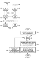
With reference now to FIG. 9, a flowchart illustrating an exemplary process for detecting failure of an FCoE switch is shown in accordance with an illustrative embodiment. The process shown in FIG. 9 may be implemented in an FCoE network, such as FCoE network 300 in FIG. 3.
The process begins when an FCoE switch, such as FCoE switch 303 in FIG. 3, detects failure of another FCoE switch (step 902). After detecting the failure of the other switch in step 902, the FCoE switch makes a determination as to whether the failed switch is the master switch (step 904). If the failed switch is not the mater switch, no output of step 904, then the process proceeds to step 916. If the failed switch is the mater switch, yes output of step 904, then the FCoE switch sends its priority number to the other FCoE switches connected to the network (step 906). Subsequent to the FCoE switch sending its priority number to the other FCoE switches in step 906, the FCoE switch receives the priority numbers from the other FCoE switches (step 908).
Then, the FCoE switch makes a determination as to whether the FCoE switch has the highest priority number (step 910). If the FCoE switch does not have the highest priority number, no output of step 910, then the FCoE switch remains as a backup switch (step 912). Thereafter, the process proceeds to step 916. If the FCoE switch does have the highest priority number, yes output of step 910, then the FCoE switch becomes the master switch (step 914).
After becoming the master switch in step 914, the FCoE switch takes over the MAC addresses on the Ethernet side of the fabric for the failed switch (step 916). In an alternative illustrative embodiment, instead of taking over all the MAC addresses from the failed switch, the master FCoE switch selects one or more backup FCoE switches to take over certain MAC addresses from the failed switch and instructs the selected backup switches to perform the MAC address take over accordingly. Subsequently, the FCoE switches respond to FC network side discovery or configuration requests as one domain (step 918). The process terminates thereafter.
Thus, illustrative embodiments provide a computer implemented method, system, and computer program product for creating and utilizing a virtual switch in an FCoE storage area network. The flowchart and block diagrams in the Figures illustrate the architecture, functionality, and operation of possible implementations of systems, methods and computer program products according to various embodiments of the present invention. In this regard, each block in the flowchart or block diagrams may represent a module, segment, or portion of code, which comprises one or more executable instructions for implementing the specified logical function(s). It should also be noted that, in some alternative implementations, the functions noted in the block may occur out of the order noted in the figures. For example, two blocks shown in succession may, in fact, be executed substantially concurrently, or the blocks may sometimes be executed in the reverse order, depending upon the functionality involved. It will also be noted that each block of the block diagrams and/or flowchart illustration, and combinations of blocks in the block diagrams and/or flowchart illustration, can be implemented by special purpose hardware-based systems that perform the specified functions or acts, or combinations of special purpose hardware and computer instructions.
The terminology used herein is for the purpose of describing particular embodiments only and is not intended to be limiting of the invention. As used herein, the singular forms “a”, “an” and “the” are intended to include the plural forms as well, unless the context clearly indicates otherwise. It will be further understood that the terms “comprises” and/or “comprising,” when used in this specification, specify the presence of stated features, integers, steps, operations, elements, and/or components, but do not preclude the presence or addition of one or more other features, integers, steps, operations, elements, components, and/or groups thereof.
The corresponding structures, materials, acts, and equivalents of all means or step plus function elements in the claims below are intended to include any structure, material, or act for performing the function in combination with other claimed elements as specifically claimed. The description of the present invention has been presented for purposes of illustration and description, but is not intended to be exhaustive or limited to the invention in the form disclosed. Many modifications and variations will be apparent to those of ordinary skill in the art without departing from the scope and spirit of the invention. The embodiment was chosen and described in order to best explain the principles of the invention and the practical application, and to enable others of ordinary skill in the art to understand the invention for various embodiments with various modifications as are suited to the particular use contemplated.
The invention can take the form of an entirely hardware embodiment, an entirely software embodiment or an embodiment containing both hardware and software elements. In a preferred embodiment, the invention is implemented in software, which includes but is not limited to firmware, resident software, microcode, etc.
Furthermore, the invention can take the form of a computer program product accessible from a computer-usable or computer-readable medium providing program code for use by or in connection with a computer or any instruction execution system. For the purposes of this description, a computer-usable or computer readable medium can be any tangible apparatus that can contain or store the program for use by or in connection with the instruction execution system, apparatus, or device.
The medium can be an electronic, magnetic, optical, electromagnetic, or semiconductor system (or apparatus or device). Examples of a computer-readable medium include a semiconductor or solid state memory, magnetic tape, a removable computer diskette, a random access memory (RAM), a read-only memory (ROM), a rigid magnetic disk and an optical disk. Current examples of optical disks include compact disk—read only memory (CD-ROM), compact disk—read/write (CD-R/W) and DVD.
A data processing system suitable for storing and/or executing program code will include at least one processor coupled directly or indirectly to memory elements through a system bus. The memory elements can include local memory employed during actual execution of the program code, bulk storage, and cache memories which provide temporary storage of at least some program code in order to reduce the number of times code must be retrieved from bulk storage during execution.
Input/output or I/O devices (including but not limited to keyboards, displays, pointing devices, etc.) can be coupled to the system either directly or through intervening I/O controllers.
Network adapters may also be coupled to the system to enable the data processing system to become coupled to other data processing systems or remote printers or storage devices through intervening private or public networks. Modems, cable modem and Ethernet cards are just a few of the currently available types of network adapters.
The description of the present invention has been presented for purposes of illustration and description, and is not intended to be exhaustive or limited to the invention in the form disclosed. Many modifications and variations will be apparent to those of ordinary skill in the art. The embodiment was chosen and described in order to best explain the principles of the invention, the practical application, and to enable others of ordinary skill in the art to understand the invention for various embodiments with various modifications as are suited to the particular use contemplated.

Claims (20)

1. A computer implemented method for using a virtual switch in a network, the computer implemented method comprising:
responsive to a switch connecting to the network, reading network configuration data to determine whether the switch is part of the virtual switch;
responsive to determining that the switch is part of the virtual switch, sending a priority number for the switch to other switches in the virtual switch connected to the network;
receiving priority numbers from the other switches in the virtual switch;
determining whether the switch has a highest priority number;
responsive to determining that the switch does have the highest priority number, selecting the switch to become a master switch for the virtual switch;
sending domain identification data for the virtual switch to the other switches in the virtual switch, wherein the master switch and the other switches in the virtual switch respond to a plurality of requests over the network as one domain identified by the domain identification data for the virtual switch;
responsive to receiving a request within the plurality of requests over the network, determining by the master switch an appropriate switch within the virtual switch to respond to the request so that all switches in the virtual switch participate in routing data in the network; and
instructing by the master switch the appropriate switch within the virtual switch to respond to the request.
2. The computer implemented method of claim 1, further comprising:
responsive to determining that the switch does not have the highest priority number, the switch becoming a backup switch for the virtual switch; and
receiving the domain identification data for the virtual switch from the master switch.
3. The computer implemented method of claim 1, further comprising:
responsive to determining that the switch is not part of the virtual switch, performing normal initialization.
4. The computer implemented method of claim 1, further comprising:
responsive to receiving the request within the plurality of requests over the network, determining whether the switch receiving the request is the master switch.
5. The computer implemented method of claim 4, further comprising:
responsive to determining that the switch receiving the request is not the master switch, forwarding the request to the master switch.
6. The computer implemented method of claim 1, further comprising:
responsive to selecting the switch to become the master switch, assigning by the master switch, port identification data, to end port in the network based on the domain identification data for the virtual switch; and
sending the port identification data assigned to the end ports in the network by the master switch to the other switches in the virtual switch.
7. The computer implemented method of claim 1, further comprising:
responsive to detecting a failed master switch and to determining that the switch does have the highest priority number, taking over, by the master switch, media access control from the failed master switch.
8. The computer implemented method of claim 7, wherein the switch taking over the media access control addresses from the failed master switch selects one or more of the other switches in the virtual switch to take over certain media access control addresses within the media access control addresses taken over from the failed master switch and instructs the one or more of the other switches in the virtual switch selected to perform take over of the certain media access control addresses accordingly.
9. The computer implemented method of claim 1, wherein the master switch and the other switches in the virtual switch interconnect a fibre channel fabric and an Ethernet fabric.
10. The computer implemented method of claim 1, wherein the master switch and the other switches in the virtual switch make up the virtual switch, and wherein the master switch and the other switches in the virtual switch share a common domain identification number.
11. The computer implemented method of claim 6, wherein a switch failure does not require the port identification data for the end ports to change.
12. The computer implemented method of claim 1, wherein the network is a fiber channel over an Ethernet network, and wherein the fiber channel over the Ethernet network maps a fibre channel fabric over an Ethernet fabric.
13. The computer implemented method of claim 12, wherein the fibre channel over the Ethernet network is a fibre channel over Ethernet storage area network.
14. The computer implemented method of claim 1, wherein the network configuration data is stored in the switch, and wherein the network configuration data includes a list of the other switches in the virtual switch, the priority numbers for the other switches in the virtual switch, and whether the switch is part of the virtual switch.
15. The computer implemented method of claim 1, wherein the master switch and the other switches in the virtual switch are fibre channel over Ethernet switches.
16. A data processing system for using a virtual switch in a network, comprising:
a bus system;
a storage device connected to the bus system, wherein the storage device includes a set of instructions; and
a processing unit connected to the bus system, wherein the processing unit executes the set of instructions to read network configuration data to determine whether a switch is part of the virtual switch in response to the switch connecting to the network; send a priority number for the switch to other switches in the virtual switch connected to the network in response to determining that the switch is part of the virtual switch; receive priority numbers from the other switches in the virtual switch; determine whether the switch has a highest priority number; select the switch to be a master switch for the virtual switch in response to determining that the switch does have the highest priority number; send domain identification data for the virtual switch to the other switches in the virtual switch, wherein the master switch and the other switches in the virtual switch respond to a plurality of requests over the network as one domain identified by the domain identification data for the virtual switch; determine by the master switch an appropriate switch within the virtual switch to respond to a request within the plurality of requests over the network so that all switches in the virtual switch participate in routing data in the network in response to receiving the request; and instruct by the master switch the appropriate switch within the virtual switch to respond to the request.
17. A computer program product stored in a non-transitory tangible computer usable storage medium having computer usable program code embodied therein for using a virtual switch in a network, the computer program product comprising:
computer usable program code configured to read network configuration data to determine whether a switch is part of the virtual switch in response to the switch connecting to the network;
computer usable program code configured to send a priority number for the switch to other switches in the virtual switch connected to the network in response to determining that the switch is part of the virtual switch;
computer usable program code configured to receive priority numbers from the other switches in the virtual switch;
computer usable program code configured to determine whether the switch has a highest priority number;
computer usable program code configured to select the switch to be a master switch for the virtual switch in response to determining that the switch does have the highest priority number;
computer usable program code configured to send domain identification data for the virtual switch to the other switches in the virtual switch, wherein the master switch and the other switches in the virtual switch respond to a plurality of requests over the network as one domain identified by the domain identification data for the virtual switch;
computer usable program code configured to determine by the master switch an appropriate switch within the virtual switch to respond to a request within the plurality of requests over the network so that all switches in the virtual switch participate in routing data in the network in response to receiving the request; and
computer usable program code configured to instruct by the master switch the appropriate switch within the virtual switch to respond to the request.
18. The computer program product of claim 17, further comprising:
computer usable program code configured to become a backup switch for the virtual switch in response to determining that the switch does not have the highest priority number; and
computer usable program code configured to receive the domain identification data for the virtual switch from the master switch.
19. The computer program product of claim 17, further comprising:
computer usable program code configured to perform normal initialization in response to determining that the switch is not part of the virtual switch.
20. The computer program product of claim 17, further comprising:
computer usable program code configured to determine whether the switch receiving a request within the plurality of requests over the network is the master switch in response to receiving the request; and
computer usable program code configured to forward the request to the master switch in response to determining that the switch receiving the request is not the master switch.
US12/058,871 2008-03-31 2008-03-31 Virtual fibre channel over Ethernet switch Expired - Fee Related US7792148B2 (en)

Priority Applications (1)

Application Number Priority Date Filing Date Title
US12/058,871 US7792148B2 (en) 2008-03-31 2008-03-31 Virtual fibre channel over Ethernet switch

Applications Claiming Priority (1)

Application Number Priority Date Filing Date Title
US12/058,871 US7792148B2 (en) 2008-03-31 2008-03-31 Virtual fibre channel over Ethernet switch

Publications (2)

Publication Number Publication Date
US20090245242A1 US20090245242A1 (en) 2009-10-01
US7792148B2 true US7792148B2 (en) 2010-09-07

Family

ID=41117105

Family Applications (1)

Application Number Title Priority Date Filing Date
US12/058,871 Expired - Fee Related US7792148B2 (en) 2008-03-31 2008-03-31 Virtual fibre channel over Ethernet switch

Country Status (1)

Country Link
US (1) US7792148B2 (en)

Cited By (19)

* Cited by examiner, † Cited by third party
Publication number Priority date Publication date Assignee Title
US20110135303A1 (en) * 2009-12-07 2011-06-09 John Lewis Hufferd DIRECT MODE ADAPTER BASED SHORTCUT FOR FCoE DATA TRANSFER
US20110176412A1 (en) * 2010-01-19 2011-07-21 Elizabeth Stine Distributed virtual fibre channel over ethernet forwarder
US8559335B2 (en) 2011-01-07 2013-10-15 Jeda Networks, Inc. Methods for creating virtual links between fibre channel over ethernet nodes for converged network adapters
US8559433B2 (en) 2011-01-07 2013-10-15 Jeda Networks, Inc. Methods, systems and apparatus for the servicing of fibre channel fabric login frames
US8625597B2 (en) 2011-01-07 2014-01-07 Jeda Networks, Inc. Methods, systems and apparatus for the interconnection of fibre channel over ethernet devices
US8705353B1 (en) * 2007-06-13 2014-04-22 Juniper Networks, Inc. Automatic configuration of virtual network switches
US8801448B2 (en) 2009-05-22 2014-08-12 Ppc Broadband, Inc. Coaxial cable connector having electrical continuity structure
US8811399B2 (en) 2011-01-07 2014-08-19 Jeda Networks, Inc. Methods, systems and apparatus for the interconnection of fibre channel over ethernet devices using a fibre channel over ethernet interconnection apparatus controller
US8858251B2 (en) 2010-11-11 2014-10-14 Ppc Broadband, Inc. Connector having a coupler-body continuity member
US9017101B2 (en) 2011-03-30 2015-04-28 Ppc Broadband, Inc. Continuity maintaining biasing member
US9071629B2 (en) 2011-01-07 2015-06-30 Jeda Networks, Inc. Methods for the interconnection of fibre channel over ethernet devices using shortest path bridging
US9071630B2 (en) 2011-01-07 2015-06-30 Jeda Networks, Inc. Methods for the interconnection of fibre channel over ethernet devices using a trill network
US9106579B2 (en) 2011-01-07 2015-08-11 Jeda Networks, Inc. Methods, systems and apparatus for utilizing an iSNS server in a network of fibre channel over ethernet devices
US9178944B2 (en) 2011-01-07 2015-11-03 Jeda Networks, Inc. Methods, systems and apparatus for the control of interconnection of fibre channel over ethernet devices
US9203167B2 (en) 2011-05-26 2015-12-01 Ppc Broadband, Inc. Coaxial cable connector with conductive seal
US9570845B2 (en) 2009-05-22 2017-02-14 Ppc Broadband, Inc. Connector having a continuity member operable in a radial direction
US9595776B2 (en) 2011-03-30 2017-03-14 Ppc Broadband, Inc. Connector producing a biasing force
US9711917B2 (en) 2011-05-26 2017-07-18 Ppc Broadband, Inc. Band spring continuity member for coaxial cable connector
RU210386U1 (en) * 2021-10-08 2022-04-14 Общество с ограниченной ответственностью "Газпром трансгаз Ухта" CONTROLLED ETHERNET DISCONNECTOR

Families Citing this family (83)

* Cited by examiner, † Cited by third party
Publication number Priority date Publication date Assignee Title
JP4833381B2 (en) * 2008-07-01 2011-12-07 インターナショナル・ビジネス・マシーンズ・コーポレーション Storage area network, configuration method thereof, and program
US8848575B2 (en) * 2009-02-23 2014-09-30 Brocade Communications Systems, Inc. High availability and multipathing for fibre channel over ethernet
WO2010105092A1 (en) * 2009-03-12 2010-09-16 James Paul Rivers Providing fibre channel services and forwarding fibre channel over ethernet frames
US8665886B2 (en) * 2009-03-26 2014-03-04 Brocade Communications Systems, Inc. Redundant host connection in a routed network
US9106674B2 (en) * 2010-02-18 2015-08-11 Cisco Technology, Inc. Increasing the number of domain identifiers for use by a switch in an established fibre channel switched fabric
US8593943B2 (en) * 2010-03-22 2013-11-26 Cisco Technology, Inc. N—port ID virtualization node redundancy
US8369335B2 (en) 2010-03-24 2013-02-05 Brocade Communications Systems, Inc. Method and system for extending routing domain to non-routing end stations
CN102208945B (en) * 2010-03-31 2014-11-05 华为数字技术(成都)有限公司 Method for obtaining network address and FCoE target and communication system
WO2011121664A1 (en) * 2010-03-31 2011-10-06 Hitachi, Ltd. Communication network control system and control method
US8767751B2 (en) * 2010-04-30 2014-07-01 Cisco Technology, Inc. Unsolicited FIP packet injection by proxy and spoofing and autoconfiguring intermediate bridges using FIP snooping
US9270486B2 (en) 2010-06-07 2016-02-23 Brocade Communications Systems, Inc. Name services for virtual cluster switching
US9461840B2 (en) 2010-06-02 2016-10-04 Brocade Communications Systems, Inc. Port profile management for virtual cluster switching
US8989186B2 (en) 2010-06-08 2015-03-24 Brocade Communication Systems, Inc. Virtual port grouping for virtual cluster switching
US9716672B2 (en) 2010-05-28 2017-07-25 Brocade Communications Systems, Inc. Distributed configuration management for virtual cluster switching
US9769016B2 (en) 2010-06-07 2017-09-19 Brocade Communications Systems, Inc. Advanced link tracking for virtual cluster switching
US9231890B2 (en) 2010-06-08 2016-01-05 Brocade Communications Systems, Inc. Traffic management for virtual cluster switching
US8867552B2 (en) 2010-05-03 2014-10-21 Brocade Communications Systems, Inc. Virtual cluster switching
US8625616B2 (en) 2010-05-11 2014-01-07 Brocade Communications Systems, Inc. Converged network extension
US9001824B2 (en) 2010-05-18 2015-04-07 Brocade Communication Systems, Inc. Fabric formation for virtual cluster switching
EP4027611A1 (en) * 2010-05-03 2022-07-13 Avago Technologies International Sales Pte. Limited Virtual cluster switching
US9172590B2 (en) * 2010-05-11 2015-10-27 Brocade Communications Systems, Inc. Single virtual domain fibre channel over ethernet fabric
US8885488B2 (en) 2010-06-02 2014-11-11 Brocade Communication Systems, Inc. Reachability detection in trill networks
US8634308B2 (en) 2010-06-02 2014-01-21 Brocade Communications Systems, Inc. Path detection in trill networks
US9608833B2 (en) 2010-06-08 2017-03-28 Brocade Communications Systems, Inc. Supporting multiple multicast trees in trill networks
US8446914B2 (en) 2010-06-08 2013-05-21 Brocade Communications Systems, Inc. Method and system for link aggregation across multiple switches
US9628293B2 (en) 2010-06-08 2017-04-18 Brocade Communications Systems, Inc. Network layer multicasting in trill networks
US9806906B2 (en) 2010-06-08 2017-10-31 Brocade Communications Systems, Inc. Flooding packets on a per-virtual-network basis
US9246703B2 (en) 2010-06-08 2016-01-26 Brocade Communications Systems, Inc. Remote port mirroring
CN101944954A (en) * 2010-07-02 2011-01-12 中兴通讯股份有限公司 Method and system for realizing main /standby switch of single boards
US9807031B2 (en) 2010-07-16 2017-10-31 Brocade Communications Systems, Inc. System and method for network configuration
US8467311B2 (en) * 2011-03-31 2013-06-18 Broadcom Corporation Method and system for avoiding flooding of packets in switches
US9270572B2 (en) 2011-05-02 2016-02-23 Brocade Communications Systems Inc. Layer-3 support in TRILL networks
US8948056B2 (en) 2011-06-28 2015-02-03 Brocade Communication Systems, Inc. Spanning-tree based loop detection for an ethernet fabric switch
US9407533B2 (en) 2011-06-28 2016-08-02 Brocade Communications Systems, Inc. Multicast in a trill network
US9401861B2 (en) 2011-06-28 2016-07-26 Brocade Communications Systems, Inc. Scalable MAC address distribution in an Ethernet fabric switch
US8879549B2 (en) 2011-06-28 2014-11-04 Brocade Communications Systems, Inc. Clearing forwarding entries dynamically and ensuring consistency of tables across ethernet fabric switch
US9007958B2 (en) 2011-06-29 2015-04-14 Brocade Communication Systems, Inc. External loop detection for an ethernet fabric switch
US8885641B2 (en) 2011-06-30 2014-11-11 Brocade Communication Systems, Inc. Efficient trill forwarding
US9736085B2 (en) 2011-08-29 2017-08-15 Brocade Communications Systems, Inc. End-to end lossless Ethernet in Ethernet fabric
US9699117B2 (en) 2011-11-08 2017-07-04 Brocade Communications Systems, Inc. Integrated fibre channel support in an ethernet fabric switch
US9450870B2 (en) 2011-11-10 2016-09-20 Brocade Communications Systems, Inc. System and method for flow management in software-defined networks
US8995272B2 (en) 2012-01-26 2015-03-31 Brocade Communication Systems, Inc. Link aggregation in software-defined networks
US9742693B2 (en) 2012-02-27 2017-08-22 Brocade Communications Systems, Inc. Dynamic service insertion in a fabric switch
US9154416B2 (en) 2012-03-22 2015-10-06 Brocade Communications Systems, Inc. Overlay tunnel in a fabric switch
US9374301B2 (en) 2012-05-18 2016-06-21 Brocade Communications Systems, Inc. Network feedback in software-defined networks
US10277464B2 (en) 2012-05-22 2019-04-30 Arris Enterprises Llc Client auto-configuration in a multi-switch link aggregation
CN104272668B (en) 2012-05-23 2018-05-22 博科通讯系统有限公司 Layer 3 covers gateway
US9602430B2 (en) 2012-08-21 2017-03-21 Brocade Communications Systems, Inc. Global VLANs for fabric switches
US9401872B2 (en) 2012-11-16 2016-07-26 Brocade Communications Systems, Inc. Virtual link aggregations across multiple fabric switches
EP2928129B1 (en) 2012-12-18 2018-05-09 Huawei Technologies Co., Ltd. Method and network devices for determining an administrative domain in a virtual cluster
US9350680B2 (en) 2013-01-11 2016-05-24 Brocade Communications Systems, Inc. Protection switching over a virtual link aggregation
US9548926B2 (en) 2013-01-11 2017-01-17 Brocade Communications Systems, Inc. Multicast traffic load balancing over virtual link aggregation
US9413691B2 (en) 2013-01-11 2016-08-09 Brocade Communications Systems, Inc. MAC address synchronization in a fabric switch
US9565113B2 (en) 2013-01-15 2017-02-07 Brocade Communications Systems, Inc. Adaptive link aggregation and virtual link aggregation
US9565099B2 (en) 2013-03-01 2017-02-07 Brocade Communications Systems, Inc. Spanning tree in fabric switches
WO2014145750A1 (en) 2013-03-15 2014-09-18 Brocade Communications Systems, Inc. Scalable gateways for a fabric switch
US9699001B2 (en) 2013-06-10 2017-07-04 Brocade Communications Systems, Inc. Scalable and segregated network virtualization
US9565028B2 (en) 2013-06-10 2017-02-07 Brocade Communications Systems, Inc. Ingress switch multicast distribution in a fabric switch
US9806949B2 (en) 2013-09-06 2017-10-31 Brocade Communications Systems, Inc. Transparent interconnection of Ethernet fabric switches
US9912612B2 (en) 2013-10-28 2018-03-06 Brocade Communications Systems LLC Extended ethernet fabric switches
US9548873B2 (en) 2014-02-10 2017-01-17 Brocade Communications Systems, Inc. Virtual extensible LAN tunnel keepalives
US10581758B2 (en) 2014-03-19 2020-03-03 Avago Technologies International Sales Pte. Limited Distributed hot standby links for vLAG
US10476698B2 (en) 2014-03-20 2019-11-12 Avago Technologies International Sales Pte. Limited Redundent virtual link aggregation group
US10063473B2 (en) 2014-04-30 2018-08-28 Brocade Communications Systems LLC Method and system for facilitating switch virtualization in a network of interconnected switches
US9800471B2 (en) 2014-05-13 2017-10-24 Brocade Communications Systems, Inc. Network extension groups of global VLANs in a fabric switch
US10616108B2 (en) 2014-07-29 2020-04-07 Avago Technologies International Sales Pte. Limited Scalable MAC address virtualization
US9544219B2 (en) 2014-07-31 2017-01-10 Brocade Communications Systems, Inc. Global VLAN services
US9807007B2 (en) 2014-08-11 2017-10-31 Brocade Communications Systems, Inc. Progressive MAC address learning
US9524173B2 (en) 2014-10-09 2016-12-20 Brocade Communications Systems, Inc. Fast reboot for a switch
US9699029B2 (en) 2014-10-10 2017-07-04 Brocade Communications Systems, Inc. Distributed configuration management in a switch group
US9626255B2 (en) 2014-12-31 2017-04-18 Brocade Communications Systems, Inc. Online restoration of a switch snapshot
US9628407B2 (en) 2014-12-31 2017-04-18 Brocade Communications Systems, Inc. Multiple software versions in a switch group
US9942097B2 (en) 2015-01-05 2018-04-10 Brocade Communications Systems LLC Power management in a network of interconnected switches
US10003552B2 (en) 2015-01-05 2018-06-19 Brocade Communications Systems, Llc. Distributed bidirectional forwarding detection protocol (D-BFD) for cluster of interconnected switches
US10038592B2 (en) 2015-03-17 2018-07-31 Brocade Communications Systems LLC Identifier assignment to a new switch in a switch group
US9807005B2 (en) 2015-03-17 2017-10-31 Brocade Communications Systems, Inc. Multi-fabric manager
US10579406B2 (en) 2015-04-08 2020-03-03 Avago Technologies International Sales Pte. Limited Dynamic orchestration of overlay tunnels
US10439929B2 (en) 2015-07-31 2019-10-08 Avago Technologies International Sales Pte. Limited Graceful recovery of a multicast-enabled switch
US10171303B2 (en) 2015-09-16 2019-01-01 Avago Technologies International Sales Pte. Limited IP-based interconnection of switches with a logical chassis
US9912614B2 (en) 2015-12-07 2018-03-06 Brocade Communications Systems LLC Interconnection of switches based on hierarchical overlay tunneling
US10630590B2 (en) * 2016-07-14 2020-04-21 Mellanox Technologies Tlv Ltd. Credit loop deadlock detection and recovery in arbitrary topology networks
US10237090B2 (en) 2016-10-28 2019-03-19 Avago Technologies International Sales Pte. Limited Rule-based network identifier mapping
CN115150690B (en) * 2022-09-06 2022-11-15 武汉长光科技有限公司 Hierarchical quality of service distribution method, optical line terminal and storage medium

Citations (12)

* Cited by examiner, † Cited by third party
Publication number Priority date Publication date Assignee Title
US20030026267A1 (en) 2001-07-31 2003-02-06 Oberman Stuart F. Virtual channels in a network switch
US20040003140A1 (en) 2002-05-06 2004-01-01 Todd Rimmer Network data flow optimization
US6704812B2 (en) 2000-11-30 2004-03-09 International Business Machines Corporation Transparent and dynamic management of redundant physical paths to peripheral devices
US20040081087A1 (en) 2002-09-09 2004-04-29 Shea Michael John Method, apparatus and program storage device for verifying existence of a redundant fibre channel path
US6819654B2 (en) 2001-09-25 2004-11-16 Mcdata Corporation Trunking inter-switch links
US20050050243A1 (en) 2003-08-29 2005-03-03 Clark Stacey A. Modified core-edge topology for a fibre channel network
US6895528B2 (en) 2000-08-07 2005-05-17 Computer Network Technology Corporation Method and apparatus for imparting fault tolerance in a switch or the like
US20060251067A1 (en) * 2004-10-22 2006-11-09 Cisco Technology, Inc., A Corporation Of California Fibre channel over ethernet
US20070058620A1 (en) * 2005-08-31 2007-03-15 Mcdata Corporation Management of a switch fabric through functionality conservation
US20070098012A1 (en) 2003-01-21 2007-05-03 Nextlo Inc. Method and apparatus for shared i/o in a load/store fabric
US7281169B2 (en) 2004-01-30 2007-10-09 Dell Products L.P. Method, software and system for multi-path fail-over recovery in sequential storage systems
US7558195B1 (en) * 2002-04-16 2009-07-07 Foundry Networks, Inc. System and method for providing network route redundancy across layer 2 devices

Patent Citations (12)

* Cited by examiner, † Cited by third party
Publication number Priority date Publication date Assignee Title
US6895528B2 (en) 2000-08-07 2005-05-17 Computer Network Technology Corporation Method and apparatus for imparting fault tolerance in a switch or the like
US6704812B2 (en) 2000-11-30 2004-03-09 International Business Machines Corporation Transparent and dynamic management of redundant physical paths to peripheral devices
US20030026267A1 (en) 2001-07-31 2003-02-06 Oberman Stuart F. Virtual channels in a network switch
US6819654B2 (en) 2001-09-25 2004-11-16 Mcdata Corporation Trunking inter-switch links
US7558195B1 (en) * 2002-04-16 2009-07-07 Foundry Networks, Inc. System and method for providing network route redundancy across layer 2 devices
US20040003140A1 (en) 2002-05-06 2004-01-01 Todd Rimmer Network data flow optimization
US20040081087A1 (en) 2002-09-09 2004-04-29 Shea Michael John Method, apparatus and program storage device for verifying existence of a redundant fibre channel path
US20070098012A1 (en) 2003-01-21 2007-05-03 Nextlo Inc. Method and apparatus for shared i/o in a load/store fabric
US20050050243A1 (en) 2003-08-29 2005-03-03 Clark Stacey A. Modified core-edge topology for a fibre channel network
US7281169B2 (en) 2004-01-30 2007-10-09 Dell Products L.P. Method, software and system for multi-path fail-over recovery in sequential storage systems
US20060251067A1 (en) * 2004-10-22 2006-11-09 Cisco Technology, Inc., A Corporation Of California Fibre channel over ethernet
US20070058620A1 (en) * 2005-08-31 2007-03-15 Mcdata Corporation Management of a switch fabric through functionality conservation

Non-Patent Citations (3)

* Cited by examiner, † Cited by third party
Title
"Fibre Channel Standard Hub-Loop Redundancy for Higher RAS", IBM Corp. vol. 37, No. 04A, Apr. 1994, pp. 383-385.
Baldwin et al., "Innovation for Making Virtual Storage Area Networks", IBM, pp. 1-2.
Kubo et al., "In-Band Control of Indicators to Identify Devices Distributed on the Same Domain", IBM, pp. 1-3.

Cited By (43)

* Cited by examiner, † Cited by third party
Publication number Priority date Publication date Assignee Title
US9929911B1 (en) * 2007-06-13 2018-03-27 Juniper Networks, Inc. Automatic configuration of virtual network switches
US9172609B1 (en) 2007-06-13 2015-10-27 Juniper Networks, Inc. Automatic configuration of virtual network switches
US8705353B1 (en) * 2007-06-13 2014-04-22 Juniper Networks, Inc. Automatic configuration of virtual network switches
US8801448B2 (en) 2009-05-22 2014-08-12 Ppc Broadband, Inc. Coaxial cable connector having electrical continuity structure
US10862251B2 (en) 2009-05-22 2020-12-08 Ppc Broadband, Inc. Coaxial cable connector having an electrical grounding portion
US10931068B2 (en) 2009-05-22 2021-02-23 Ppc Broadband, Inc. Connector having a grounding member operable in a radial direction
US9419389B2 (en) 2009-05-22 2016-08-16 Ppc Broadband, Inc. Coaxial cable connector having electrical continuity member
US9496661B2 (en) 2009-05-22 2016-11-15 Ppc Broadband, Inc. Coaxial cable connector having electrical continuity member
US9570845B2 (en) 2009-05-22 2017-02-14 Ppc Broadband, Inc. Connector having a continuity member operable in a radial direction
US9660398B2 (en) 2009-05-22 2017-05-23 Ppc Broadband, Inc. Coaxial cable connector having electrical continuity member
US8843659B2 (en) 2009-12-07 2014-09-23 John L. Hufferd Direct mode adapter based shortcut for FCoE data transfer
US8713162B2 (en) 2009-12-07 2014-04-29 John Lewis Hufferd Direct mode adapter based shortcut for FCoE data transfer
US20110135303A1 (en) * 2009-12-07 2011-06-09 John Lewis Hufferd DIRECT MODE ADAPTER BASED SHORTCUT FOR FCoE DATA TRANSFER
US20110176412A1 (en) * 2010-01-19 2011-07-21 Elizabeth Stine Distributed virtual fibre channel over ethernet forwarder
US8446817B2 (en) * 2010-01-19 2013-05-21 Cisco Technology, Inc. Distributed virtual fibre channel over Ethernet forwarder
US8858251B2 (en) 2010-11-11 2014-10-14 Ppc Broadband, Inc. Connector having a coupler-body continuity member
US8915754B2 (en) 2010-11-11 2014-12-23 Ppc Broadband, Inc. Connector having a coupler-body continuity member
US8920182B2 (en) 2010-11-11 2014-12-30 Ppc Broadband, Inc. Connector having a coupler-body continuity member
US8920192B2 (en) 2010-11-11 2014-12-30 Ppc Broadband, Inc. Connector having a coupler-body continuity member
US9178817B2 (en) 2011-01-07 2015-11-03 Jeda Networks, Inc. Methods, systems and apparatus for converged network adapters
US8811399B2 (en) 2011-01-07 2014-08-19 Jeda Networks, Inc. Methods, systems and apparatus for the interconnection of fibre channel over ethernet devices using a fibre channel over ethernet interconnection apparatus controller
US9178969B2 (en) 2011-01-07 2015-11-03 Jeda Networks, Inc. Methods, systems and apparatus for the servicing of fibre channel login frames
US9178821B2 (en) 2011-01-07 2015-11-03 Jeda Networks, Inc. Methods, systems and apparatus for the interconnection of fibre channel over Ethernet devices using a fibre channel over Ethernet interconnection apparatus controller
US9178944B2 (en) 2011-01-07 2015-11-03 Jeda Networks, Inc. Methods, systems and apparatus for the control of interconnection of fibre channel over ethernet devices
US8559335B2 (en) 2011-01-07 2013-10-15 Jeda Networks, Inc. Methods for creating virtual links between fibre channel over ethernet nodes for converged network adapters
US9071630B2 (en) 2011-01-07 2015-06-30 Jeda Networks, Inc. Methods for the interconnection of fibre channel over ethernet devices using a trill network
US9071629B2 (en) 2011-01-07 2015-06-30 Jeda Networks, Inc. Methods for the interconnection of fibre channel over ethernet devices using shortest path bridging
US9515844B2 (en) 2011-01-07 2016-12-06 Jeda Networks, Inc. Methods, systems and apparatus for the interconnection of fibre channel over Ethernet devices
US8559433B2 (en) 2011-01-07 2013-10-15 Jeda Networks, Inc. Methods, systems and apparatus for the servicing of fibre channel fabric login frames
US8625597B2 (en) 2011-01-07 2014-01-07 Jeda Networks, Inc. Methods, systems and apparatus for the interconnection of fibre channel over ethernet devices
US9106579B2 (en) 2011-01-07 2015-08-11 Jeda Networks, Inc. Methods, systems and apparatus for utilizing an iSNS server in a network of fibre channel over ethernet devices
US9608345B2 (en) 2011-03-30 2017-03-28 Ppc Broadband, Inc. Continuity maintaining biasing member
US9660360B2 (en) 2011-03-30 2017-05-23 Ppc Broadband, Inc. Connector producing a biasing force
US9595776B2 (en) 2011-03-30 2017-03-14 Ppc Broadband, Inc. Connector producing a biasing force
US10186790B2 (en) 2011-03-30 2019-01-22 Ppc Broadband, Inc. Connector producing a biasing force
US10559898B2 (en) 2011-03-30 2020-02-11 Ppc Broadband, Inc. Connector producing a biasing force
US9017101B2 (en) 2011-03-30 2015-04-28 Ppc Broadband, Inc. Continuity maintaining biasing member
US11811184B2 (en) 2011-03-30 2023-11-07 Ppc Broadband, Inc. Connector producing a biasing force
US9711917B2 (en) 2011-05-26 2017-07-18 Ppc Broadband, Inc. Band spring continuity member for coaxial cable connector
US10707629B2 (en) 2011-05-26 2020-07-07 Ppc Broadband, Inc. Grounding member for coaxial cable connector
US9203167B2 (en) 2011-05-26 2015-12-01 Ppc Broadband, Inc. Coaxial cable connector with conductive seal
US11283226B2 (en) 2011-05-26 2022-03-22 Ppc Broadband, Inc. Grounding member for coaxial cable connector
RU210386U1 (en) * 2021-10-08 2022-04-14 Общество с ограниченной ответственностью "Газпром трансгаз Ухта" CONTROLLED ETHERNET DISCONNECTOR

Also Published As

Publication number Publication date
US20090245242A1 (en) 2009-10-01

Similar Documents

Publication Publication Date Title
US7792148B2 (en) Virtual fibre channel over Ethernet switch
TWI383616B (en) Method and system for assigning a plurality of macs to a plurality of processors
US11082261B2 (en) Logical router comprising disaggregated network elements
US8842518B2 (en) System and method for supporting management network interface card port failover in a middleware machine environment
US9219641B2 (en) Performing failover in a redundancy group
CN102549983B (en) Distributed data center access switch
CN110535760B (en) Forwarding detection of aggregated interfaces
JP4520802B2 (en) Storage network management server, storage network management method, storage network management program, and storage network management system
US20130159487A1 (en) Migration of Virtual IP Addresses in a Failover Cluster
TWI577164B (en) Scalable address resolution
TW201029384A (en) Redundant intermediary switch solution for detecting and managing fibre channel over Ethernet (FCoE) switch failures
JP2009026295A (en) Method and device for managing virtual port on storage system
JP2015211374A (en) Information processing system, control method for information processing system, and control program for management device
JP5775473B2 (en) Edge device redundancy system, switching control device, and edge device redundancy method
JP2006100906A (en) Method for managing operation of network system and storage device
WO2016164061A1 (en) Big data transfer
JP4133738B2 (en) High-speed network address takeover method, network device, and program
US10353585B2 (en) Methods for managing array LUNs in a storage network with a multi-path configuration and devices thereof
CN111835544B (en) Monitoring method and system of virtual router based on user mode protocol stack
US20100312866A1 (en) Redundancy pair detecting method, communication device and recording medium for recording redundancy pair detection program
TW201242271A (en) Keeping a communication path smooth in a storage area network

Legal Events

Date Code Title Description
AS Assignment

Owner name: INTERNATIONAL BUSINESS MACHINES CORPORATION, NEW Y

Free format text: ASSIGNMENT OF ASSIGNORS INTEREST;ASSIGNORS:CARLSON, SCOTT M.;EISENHAUER, DANIEL G.;HATHORN, ROGER G.;AND OTHERS;REEL/FRAME:020726/0750;SIGNING DATES FROM 20080317 TO 20080325

Owner name: INTERNATIONAL BUSINESS MACHINES CORPORATION, NEW Y

Free format text: ASSIGNMENT OF ASSIGNORS INTEREST;ASSIGNORS:CARLSON, SCOTT M.;EISENHAUER, DANIEL G.;HATHORN, ROGER G.;AND OTHERS;SIGNING DATES FROM 20080317 TO 20080325;REEL/FRAME:020726/0750

REMI Maintenance fee reminder mailed
FPAY Fee payment

Year of fee payment: 4

SULP Surcharge for late payment
FEPP Fee payment procedure

Free format text: MAINTENANCE FEE REMINDER MAILED (ORIGINAL EVENT CODE: REM.)

LAPS Lapse for failure to pay maintenance fees

Free format text: PATENT EXPIRED FOR FAILURE TO PAY MAINTENANCE FEES (ORIGINAL EVENT CODE: EXP.); ENTITY STATUS OF PATENT OWNER: LARGE ENTITY

STCH Information on status: patent discontinuation

Free format text: PATENT EXPIRED DUE TO NONPAYMENT OF MAINTENANCE FEES UNDER 37 CFR 1.362

FP Lapsed due to failure to pay maintenance fee

Effective date: 20180907