US7790029B2 - Filter device having more than one filtration compartment - Google Patents
Filter device having more than one filtration compartment Download PDFInfo
- Publication number
- US7790029B2 US7790029B2 US10/708,774 US70877404A US7790029B2 US 7790029 B2 US7790029 B2 US 7790029B2 US 70877404 A US70877404 A US 70877404A US 7790029 B2 US7790029 B2 US 7790029B2
- Authority
- US
- United States
- Prior art keywords
- housing
- longitudinally extending
- shell portions
- fluid
- filtration
- Prior art date
- Legal status (The legal status is an assumption and is not a legal conclusion. Google has not performed a legal analysis and makes no representation as to the accuracy of the status listed.)
- Active, expires
Links
Images


Classifications
-
- A61M1/0023—
-
- B—PERFORMING OPERATIONS; TRANSPORTING
- B01—PHYSICAL OR CHEMICAL PROCESSES OR APPARATUS IN GENERAL
- B01D—SEPARATION
- B01D63/00—Apparatus in general for separation processes using semi-permeable membranes
- B01D63/02—Hollow fibre modules
- B01D63/04—Hollow fibre modules comprising multiple hollow fibre assemblies
-
- B—PERFORMING OPERATIONS; TRANSPORTING
- B01—PHYSICAL OR CHEMICAL PROCESSES OR APPARATUS IN GENERAL
- B01D—SEPARATION
- B01D61/00—Processes of separation using semi-permeable membranes, e.g. dialysis, osmosis or ultrafiltration; Apparatus, accessories or auxiliary operations specially adapted therefor
- B01D61/24—Dialysis ; Membrane extraction
- B01D61/30—Accessories; Auxiliary operation
-
- B—PERFORMING OPERATIONS; TRANSPORTING
- B01—PHYSICAL OR CHEMICAL PROCESSES OR APPARATUS IN GENERAL
- B01D—SEPARATION
- B01D61/00—Processes of separation using semi-permeable membranes, e.g. dialysis, osmosis or ultrafiltration; Apparatus, accessories or auxiliary operations specially adapted therefor
- B01D61/58—Multistep processes
-
- B—PERFORMING OPERATIONS; TRANSPORTING
- B01—PHYSICAL OR CHEMICAL PROCESSES OR APPARATUS IN GENERAL
- B01D—SEPARATION
- B01D63/00—Apparatus in general for separation processes using semi-permeable membranes
- B01D63/02—Hollow fibre modules
-
- B—PERFORMING OPERATIONS; TRANSPORTING
- B01—PHYSICAL OR CHEMICAL PROCESSES OR APPARATUS IN GENERAL
- B01D—SEPARATION
- B01D65/00—Accessories or auxiliary operations, in general, for separation processes or apparatus using semi-permeable membranes
-
- B—PERFORMING OPERATIONS; TRANSPORTING
- B01—PHYSICAL OR CHEMICAL PROCESSES OR APPARATUS IN GENERAL
- B01D—SEPARATION
- B01D61/00—Processes of separation using semi-permeable membranes, e.g. dialysis, osmosis or ultrafiltration; Apparatus, accessories or auxiliary operations specially adapted therefor
- B01D61/14—Ultrafiltration; Microfiltration
- B01D61/145—Ultrafiltration
-
- B—PERFORMING OPERATIONS; TRANSPORTING
- B01—PHYSICAL OR CHEMICAL PROCESSES OR APPARATUS IN GENERAL
- B01D—SEPARATION
- B01D61/00—Processes of separation using semi-permeable membranes, e.g. dialysis, osmosis or ultrafiltration; Apparatus, accessories or auxiliary operations specially adapted therefor
- B01D61/24—Dialysis ; Membrane extraction
- B01D61/243—Dialysis
-
- Y—GENERAL TAGGING OF NEW TECHNOLOGICAL DEVELOPMENTS; GENERAL TAGGING OF CROSS-SECTIONAL TECHNOLOGIES SPANNING OVER SEVERAL SECTIONS OF THE IPC; TECHNICAL SUBJECTS COVERED BY FORMER USPC CROSS-REFERENCE ART COLLECTIONS [XRACs] AND DIGESTS
- Y10—TECHNICAL SUBJECTS COVERED BY FORMER USPC
- Y10T—TECHNICAL SUBJECTS COVERED BY FORMER US CLASSIFICATION
- Y10T29/00—Metal working
- Y10T29/49—Method of mechanical manufacture
- Y10T29/49609—Spring making
- Y10T29/49613—Spring making for human comfort
Definitions
- the present invention relates to a filter device for the filtration of fluids.
- one or more embodiments of the present invention relates to filter devices for use in dialysis-type treatments and for filtration processes similar to and related to the hemodialysis process, such as hemofiltration, hemodiafiltration and ultrafiltration, as well as to a method for making a housing of a filtration device.
- Filter devices having hollow fibers or membranes are used, for example, in the area of dialysis for a wide variety of purposes.
- Such filters may be referred to as dialysers, these being used for example in hemodialysis, in which blood is directed into and along the inside of the semi-permeable walls of the hollow fibers while dialysis fluid is directed around the outside of the hollow fibers.
- Various convection and diffusion processes may thereby take place across the walls of the hollow fibers. These processes serve, for example, to purify and to remove excess fluid from the blood.
- the electrolyte concentration in the blood can be conditioned using infusion fluids, and buffers such as bicarbonate or acetate can be added to the blood.
- the hemodialysis process is effective at removing substances having a low molecular weight, but may be less effective at removing substances having a middle molecular weight.
- Low molecular weight substances in the context of dialysis typically includes substances such as urea, having a molecular weight below 5 kDa.
- Filter devices of this type may also be employed in so-called hemofiltration, in which a substitution fluid is added to the blood.
- a substitution fluid is added to the blood.
- the blood is directed through the inside of the hollow fibers, although in this case no dialysis fluid is passed around the outside of the fibers.
- excess fluids in particular water as well as waste products, are removed from the blood by means of a pressure difference across the membrane, here comprised by the semi-permeable walls of the hollow fiber.
- the substitution fluid can be added either prior or subsequent to the filtration in pre- or post-dilution modes.
- Hemofiltration is more effective at removing substances having a so-called middle molecular weight lying within the range between approximately 5 kDa- and 0 kDa such as Beta-2-Microglobulin.
- a further application for the present type of filter device includes hemodiafiltration: a combination of hemodialysis and hemofiltration, in which dialysate flows across one side of the membrane while blood flows across the other side and at the same time, a pressure gradient exists across the membrane.
- Infusion fluid may be added to the blood either prior to or after the filtration. This process can results in a higher filtration rate and is especially effective at removing substances having a low and middle molecular weight.
- a further process for which such filters are may be used is known as plasmapheresis, in which aqueous blood plasma is filtered out of the blood and returned to the blood after treatment.
- Such filter devices are also used in filtration processes such as reverse osmosis wherein undesirable substances may be removed from blood, water or other fluids.
- the above-mentioned filter devices can equally be used as so-called ultrafilters for the production of substitution or infusion fluids.
- infusion fluid may be directed into the filter across one side of a semi-permeable membrane, and is filtered across the membrane by means of a pressure difference.
- the infusion fluid can be sterile-filtered by removal of endotoxins, bacteria and other contaminants.
- Ultrafilters generally have a similar construction to dialyser-type filters although they are generally smaller in dimension and are not generally used as dialysers in the dialysis process. Ultrafilters are usually employed during a blood filtration treatment in addition to a dialysis filter, the filtrate from the ultrafilter creating the infusion fluid which is then being fed into the blood either on the blood side of the dialysis filter device or into blood in the blood tubes.
- These filter devices are usually so constructed that the hollow fibers are arranged as a loose bundle lying longitudinally within a tubular housing.
- the housing is provided at each end with an end cap and the hollow fiber bundle is arranged between the ends of the housing so that the end cap enclose the ends of the hollow fiber bundle.
- the ends of the fibers are usually embedded within and secured by a potting compound made from a two-component polymer resin. Except as noted below, the potting compound completely surrounds the ends of the hollow fibers and is molded to the inside of the ends of the housing to create a seal between the header chamber and the inside of the tubular housing.
- the extreme ends of the hollow fibers which constitute the hollow fiber bundle open out above the potting compound into a hollow space (hereafter: header chamber) located between the end cap and the end of the hollow fiber bundle. It is therefore possible, with the appropriate arrangement of inlets and outlets, to provide, in a known manner various forms of filter such as the previously mentioned hemodialysis filters, hemofilters, hemodiafilters, ultrafilters etc. Examples of the previously mentioned filters are disclosed in EP-0 305 687, EP-0 355 325 and EP-0 525 317.
- a first fluid may be directed into and through the inside of the semi-permeable hollow fibers.
- This first fluid may exit from the fiber column having had certain substances removed and possibly certain substances added.
- a second fluid may be present on the outside of the hollow fibers.
- This second fluid can either flow through the housing, past and around the hollow fibers, via appropriately located inlet and outlet means, or it can be removed from the first fluid and directed out of the housing via a suitable outlet, for example by means of a pressure differential across the hollow fiber membrane.
- This second fluid may be a purified form of the first fluid, a dialysis fluid for the exchange of substances into and out of the first fluid across the hollow-fiber membranes, or a waste fluid removed from the first fluid, among others.
- various fluid lines are connected to it. These fluid lines on the one hand lead blood from the patient to the blood side of the filter and then back to the patient. Additional fluid lines lead the dialysis fluid from a dialysis fluid supply, controlled by a dialysis machine, also sometimes referred to as a dialysis monitoring device, to the dialysate side of the filter and after passage through the filter further to a drain.
- the blood side here refers to the area of the filter through which the blood of the patient is led, while the dialysate side refers to the area of the filter or the filter housing through which the dialysis fluid is lea.
- the blood side and the dialysate side are separated from each other in the filter housing by the one or more semi-permeable membrane(s) and these sides correspond respectively to the sides along which the previously mentioned first and second fluids pass.
- a hemofiltration process may be combined in series with a hemodialysis or hemodiafiltration process, thereby necessitating more than one filter device.
- a filter cartridge comprising more than one filtration compartment is disclosed for example in WO 02/47785.
- two hollow fiber bundles are arranged in adjacent compartments which are separated by a wall in which a communicating aperture is provided for the flow of filtrate or dialysate through both compartments.
- a further dialyser device is known from DE-A-196 07 162, in which a filtration device for substitution fluid is disclosed along with a hemodiafiltration device integrated within a single housing.
- Filter membrane means in the form of hollow fibers are provided within both compartments.
- One end of the hollow fibers of the filter for a substitution fluid is sealed off by means of potting compound or by a cover.
- a problem encountered with this device is that it is difficult to completely expel all of the air contained within the compartment for the substitution fluid at the start of a filtration process, both the air around the outside of the hollow fibers and in the inside of the fibers.
- Air on the inside of the fibers is pushed by liquid passing across the membranes into a header chamber at either the blood entry or exit of the dialysis compartment thereby causing unnecessary contact between blood and air in the blood flow circuit. This may be avoided by passing substitution fluid through the filtration compartment prior to passing blood through the hemodiafiltration compartment although this involves additional work for an operator. In addition, air around the outside of the membranes is not completely expelled during the initiation phase of filtration and may be fed through into the blood during a treatment. This increases the thrombogenicity of the blood filtration process. A further drawback of this disclosure exists in that filtration of the substitution fluid takes place from the outside through to the inside of the hollow fiber membranes.
- a filter device in which at least two fluid filtration compartments are provided within a tubular filter housing, the respective compartments being separated by a continuous internal wall.
- filter means in respective separate chambers of a single filter device.
- a first surface of the filter membrane means is in communication with both an inlet and an outlet.
- filter membrane means in each compartment each have a first and a second surface, wherein the first or second surface are each in fluid communication with respective external flow ports.
- the external fluid flow port may be a fluid flow port connected to a fluid supply or drain means, which fluid supply or drain means are located externally of the filter housing.
- an external fluid flow port may be connected to an inflow port in fluid flow communication with a separate filtration compartment to thereby lead away fluid emerging from a second surface of filter membrane means to be infused in a fluid involved in a separate filtration treatment in another filtration compartment.
- an infusion fluid having passed across a filtration membrane may be channeled to an inflow or outflow section of an adjacent filtration compartment in which blood is filtered.
- a first surface of the filter membrane means in each compartment is in communication with an inlet and an outlet of a fluid filtration compartment thereby insuring that air may be effectively expelled from each compartment during an initial phase of operation of each filter.
- the filter device of the invention may be operated in such a manner that fluids to be passed across a membrane means in any compartment may be passed from a first surface to a second surface of the membrane means.
- the membrane means are hollow fiber membranes
- ultrafiltration usually takes place by passing fluid at a higher pressure through the inside surfaces of the fiber membranes.
- the fluid then passes through to the outside surface and is filtered in the process.
- fluid may also be passed from second, exterior surfaces through to the first, inside surfaces of hollow fiber membranes. Filtration may be carried out from the outside surface to the inside surface using a conventional type of fiber or alternatively, using a special fiber the walls of which are adapted for filtration in the said direction.
- Such fiber may be made from a more rigid material than conventional fiber.
- the filter membrane may be comprised of a bundle of hollow fiber, preferably semi-permeable fibers, in which case the first surface designates collectively the insides of the hollow fibers in the bundle and the second surface designates the outside surfaces of the hollow fibers.
- the outside surfaces of the hollow fibers are in communication with the external fluid flow port in the above example.
- the aforementioned continuous internal wall (or walls) within the filter device of the invention divide the interior of the filter housing into separate filtration compartments, such that there is no fluid communication across the wall (or walls) between the respective filtration compartments.
- the filter device of the invention may be configured such that the respective first surface (or first surfaces) of the filter membrane means in more than one compartment are in fluid flow communication with the respective first surface (or first surfaces) of filter membrane means in at least one other compartment.
- This enables a fluid to be passed through more than one filtration process in series.
- the second surface (or surfaces) of a filter membrane means in a filtration compartment may be in fluid flow communication with a first surface (or surfaces) of a filter membrane in another compartment.
- the fluid having been purified by passing across the filter membrane of one compartment may be added to the fluid being or having been filtered in another compartment. This may be achieved, for example by means of an external flow port from one filtration compartment being connected for channeling fluid to an inlet or outlet for fluid entering or leaving a first surface of a filter membrane in another compartment.
- the tubular housing means of the filter device of the invention may have elongate longitudinally extending walls which may be of any appropriate cross-section, e.g. tubular, circular, elliptical, rectangular, or any other suitable geometry.
- the longitudinal walls include at least one external wall discontinuous about the circumference, and one or more internal walls extending between opposite ends of the housing. The one or more internal walls divide the interior of the external housing into two or more internal compartments.
- more than one blood filtration process may be carried out in addition to an ultrafiltration.
- the outlet portion of the hollow fiber in one filtration compartment may be in fluid communication with the inlet portion of a bundle of hollow fiber in another compartment of the filter device.
- a replacement infusion fluid ultrafiltered in one compartment of the filter device may then be added to the blood at any stage in the blood filtration process before, after or in one or more of the other compartments of the filter device; e.g. before passage of the blood through the membranes (pre-dilution), between successive treatments (mid-dilution) or after both treatments (post-dilution).
- a first fluid such as an infusion fluid may be treated in a first compartment while a second fluid (usually blood, the first fluid being an infusion solution described above) may be subjected to more than one filtration process in series.
- a hemofiltration treatment may be carried out in a second compartment, the fluid thereby removed from the second fluid escaping from the filter through an external fluid flow port.
- the second fluid emerging at a fluid outlet of the membranes of the said second compartment may then be directed into the filtration membranes of a third filtration chamber.
- semi-permeable hollow fibers are used as a filter membrane means, these may be held in place at their ends by a so-called potting compound.
- the potting compound may consist of a hardened polymer resin, such as two component polyurethane, molded to the internal walls of the tubular housing and serves as a barrier enclosing the second surface of the membranes within a compartment of the tubular housing. It also maintains the apertures of the hollow fiber such that the (internal) first surfaces of the fiber are open at an outlet or inlet end of the housing.
- the ends of the housing are advantageously enclosed by end cap, thereby providing so-called header chambers.
- Each end cap may be constructed so as to enclose more than one header chamber, with each header chamber being provided with at least one fluid inflow or outflow port, and possibly with at least one or more additional fluid flow ports, for example for supplying additives to the fluid within the header chamber.
- each end cap may enclose each header chamber in correspondence with each of the filtration compartments internal of the overall filter housing.
- the header chambers of a single end cap may be separated from one another by wall means and by a seal member placed between the header chamber wall and an internal wall and/or the surface of the potting compound in order to prevent migration of fluid from one header chamber to another.
- the hollow fiber bundle of more than one filtration compartment may open out into a single header chamber.
- header chambers may be connected for fluid flow by connecting together fluid flow ports of respective header chambers using molded or tubing line conduit means.
- the tubular housing of the filter device may be provided, as already mentioned, with any appropriate cross-section.
- the tubular housing comprises continuous internal walls, which divide the filter into separate filtration compartments. No single compartment would thereby be delimited entirely by peripheral or external walls of the housing, each compartment being delimited at least partly by an internal walls.
- the housing may for example be tubular, and in one embodiment may be made up of two separate longitudinally extending sections of a housing wall.
- the respective portions of the tubular housing may be joined together along seam-type joints by any suitable means such as by bonding or welding e.g. using ultrasound or laser welding. In the case of laser-welding techniques, the two sections of the filter housing would benefit from particular light reflective properties in order to ensure an adequate weld.
- one of the housing sections may be made from substantially clear, uncolored material, while the other may contains a light-reflective dye suitable for causing plastics material at the boundary of the two housing portions to melt sufficiently to form a bond.
- one housing portion may be made from polycarbonate while another section may be made from polypropylene.
- Assembly of the filter device may be achieved by combining the steps of filling the respective filtration compartments as initially defined by the separate sections with hollow fiber and then assembling the tubular housing.
- hollow fiber may be placed within the respective filtration compartments defined by a respective single section of the tubular housing.
- the further housing sections may then be brought together and fixed in position enclosing the respective fiber bundles in their compartments in a manner similar to filling an internal space upon which a lid or cover is then placed.
- the housing which is here, by way of example, shown as tubular sections, may thereby each include corresponding portions of internal walls, whereby the respective edges of the various corresponding wall portions would then desirably be required to be bonded to one another as would the outer walls of the said sections. Bonding may be carried out by any suitable method such as by using adhesive means or by welding as described more fully herein.
- the internal wall may not be in portions but instead may be provided integral with a first one of the tubular housing sections, with the second section comprising only an outer wall portion of the housing joined on its internal face to the respective internal and outer wall portions of the aforementioned first section.
- the first section is likely to be somewhat larger than the second section.
- the first section may make up more than half of the outer circumference or periphery of the resulting housing, while the second portion may make up less than one half of the outer periphery, perhaps as little as one third or one quarter.
- one side of the cross-sectional rectangle may be comprised of the second portion or cover portion, while the main first portion of the housing could comprises substantially three sides of the said cross-sectional rectangle.
- internal walls could advantageously be provided integral with the said first portion, or with both portions.
- At least one outer wall of a respective filtration compartment may be provided parallel to an internal wall of a same compartment. This feature may enables a more optimal filling of the fiber bundle within each compartment.
- An end of the housing portion may be provided with one or more apertures or recesses for engaging the potting compound, which restrains the ends of the hollow fiber bundles.
- Such an embodiment may be useful when the end cap are provided with fluid flow ports for more than one fluid intended to be channeled towards different surfaces of the hollow fiber.
- the fluid intended to flow around the outside of the hollow fiber may flow though a peripheral flow port of an end cap and around a channel formed and bounded by a sill portion of the tubular housing and then through a filtration compartment of the tubular housing.
- It is an object of the present invention, therefore, to provide a filter device comprising a housing, the housing enclosing at least two fluid filtration compartments and comprising at least two longitudinally extending shell portions, one of the longitudinally extending shell portions of the housing describing less than one half of the perimeter of said housing.
- Another object of the invention is to provide a filter wherein at least one filtration compartment comprises at least two spaced apart generally planar walls and the walls are in a parallel relationship to each other.
- a further object of the invention is to provide a filter comprising an internal wall having a first part and a second part, the first part being attached to a first longitudinally extending shell portion and the second part being attached to a second longitudinally extending shell portion, the first part having a free edge and the second part having a free edge, the free edges being configured to join to each other.
- the free edge of a wall part attached to a shell portion may not be co-planar with the longitudinal edges of that shell portion.
- Yet another object of the invention is to provide a filter wherein one of the longitudinally extending shell portions comprises a substantially clear, uncolored material at at least a boundary thereof and wherein another of said longitudinally extending shell portions comprises a colored material at at least a boundary of said another shell portion, whereby a laser or electromagnetic radiation weld may be formed between the boundaries of said shell portions.
- Another object of the invention is to provide a method of making a filter device comprising the steps of forming a housing for enclosing at least two fluid filtration compartments, the housing comprising at least two longitudinally extending shell portions, one of said longitudinally extending shell portions of the housing describing less than one half of the perimeter of said housing, adjacent filtration compartments being separated from each other by an internal wall, placing at least one filter membrane having a first surface and a second surface longitudinally in each filtration compartment; closing the shell portions around the filter membranes to form said fluid filtration compartments; sealing adjacent edges of said shell portions; imbedding ends of the filter membranes in a potting compound; and capping the ends of the housing.
- a further object of the invention is to provide a method of assembling a filter further comprising forming one of the longitudinally extending shell portions from a first material having a first refractive index and another of said longitudinally extending shell portions from a second material having a second and different refractive index, sealing adjacent edges by differential heating by laser or electromagnetic radiation.
- the present invention also encompasses a method of making the filter housing of the invention in which the housing is made from two longitudinally extending portions which are bonded together along seam-type joins.
- a preferred method of bonding is by welding, in particular by laser or ultrasound welding.
- FIG. 1 is an external perspective isometric view of a filter device with two chambers.
- FIG. 2 is a longitudinal section view of the device shown in FIG. 1 .
- FIG. 2 a is a longitudinal section view of an alternative construction of the filter device such as shown in FIG. 2 .
- FIG. 3 is a partial longitudinal section view showing detail of an end of a filter device shown in FIGS. 1 and 2 .
- FIG. 4 is a cross-section view of a middle portion of a filter device taken along line IV-IV of FIG. 2
- FIG. 5 is a cross-section view of an end portion of a filter device taken along line V-V of FIG. 2
- FIG. 5 a is a cross-section view of an end portion of an alternative construction of the filter device taken along line Va-Va of FIG. 2 a
- FIG. 6 is a detailed view of one end of a tubular housing with the header cap removed.
- FIG. 7 is an isometric perspective view of a filter device having three filtration compartments.
- FIG. 8 is an isometric perspective partial view of an end of the housing of the filter device of FIG. 7 .
- FIGS. 9 and 9 a are longitudinal section views of a three-compartment filtration device.
- FIG. 10 is a cross-section of an end of the filtration device of FIG. 9 ., taken along line X-X of FIG. 9
- FIGS. 11 and 11 a are end views of a dismantled and assembled shell portion of a housing.
- FIG. 12 is an isometric view of a disassembled housing.
- FIGS. 13 and 13 a are end views of a further dismantled and assembled housing.
- the filter device shown in FIGS. 1 , 2 and 3 comprises a tubular housing 1 and two end cap 13 and 14 , one arranged at each end of the housing.
- the housing 1 is comprised of a longitudinally extending, generally tubular wall having two opposed ends. Respective compartments 2 and 3 are separated by a continuous wall means 8 .
- Filter membrane means (not shown) are arranged longitudinally within respective filtration compartments 2 and 3 ( FIGS. 2 and 3 ). These usually each comprise a bundle of semi-permeable hollow fibers secured at their ends by a potting compound 12 ( FIG. 3 ), which extends around an end portion of the wall of the housing 1 .
- the open ends of the hollow fibers, embedded as shown in the potting compound 12 constitute inlet or outlet apertures 4 a , 4 b and 5 a , 5 b for fluid entering or leaving a filtration compartment along a first surface of the filter membrane means therein.
- the open apertures 4 a , 4 b and 5 a , 5 b 4 , 5 of the ends of the hollow fibers open out into a respective header chamber 17 , 18 arranged within the end caps 13 , 14 .
- the respective compartments 2 and 3 are separated by a continuous wall means 8 .
- Fluid inflow and outflow ports 6 , 7 , 15 , 15 a , 16 and 16 a for a respective first and second fluids are arranged on the end cap 13 and 14 and 14 .
- Ports 15 and 16 and 15 a and 16 a are in fluid flow communication with header chambers 17 , 18 and 17 a , 18 a inside each end cap 13 , 14 and with a first surface of the filter membranes of each filtration compartment 2 , 3 .
- External fluid flow ports 6 , 7 and 71 are illustrated in fluid flow communication with a respective second side of the filter membranes of each of the respective filtration compartments 2 , 3 arranged within the housing 1 .
- the fluid flow ports 6 , 7 , 11 could optionally be provided on portions of the wall of the housing 1 nearby but not necessarily integral with an end caps shown in ( FIGS. 2 and 2 a )
- a conduit means 19 may be provided for conducting a fluid emerging from the second surface of the filter membranes of a filtration compartment 3 via an external fluid flow port 7 and an optional additional fluid inflow port 22 (see FIGS. 1 and 3 ) into the header chamber 17 which is in fluid flow connection with another fluid passing along a first surface of filter membrane means of a separate filtration compartment 2 .
- the ultrafiltrate emerging from an ultrafilter arranged in filtration compartment 3 within the tubular housing 1 may be used to dilute another fluid such as blood, being filtered, by hemofiltration or hemodialysis or hemodiafiltration in additional, discrete filtration compartment 2 .
- the infusion fluid is generated in a filtration compartment at a higher pressure than the pressure of the first fluid such as blood in the inflow or outflow area of the filtration compartment into which the infusion fluid is subsequently directed.
- a check or non-return valve (not shown) may be present in the conduit means 19 in order to prevent accidental passage of blood from a blood filtration compartment into the ultrafiltration compartment.
- the potting compound 12 can be anchored to the tubular housing 1 at a peripheral region and encloses a lip or flange portion 23 formed at the end of the tubular housing 1 .
- the potting compound 12 may additionally be anchored to the tubular housing at fluid distribution apertures 20 , 20 a in the housing.
- the apertures 20 , 20 a are provided in two rows in the example illustrated at FIG. 3 , and serve to enhance the flow of fluid between the enclosed peripheral channels 24 , 24 a and the respective internal filtration compartments 2 or 3 to the second surface (or the exterior surface) of the hollow fibers.
- the apertures 20 , 20 a comprise two sets of holes communicating with two separate channels 24 , 24 a (see FIG. 3 ).
- One set of holes 20 communicates with chamber 2 while the other set 20 a communicates with chamber 3 .
- These apertures 20 , 20 a may additionally serve as anchoring means for the potting compound 12 which may flow through some of the apertures while in a liquid phase prior to hardening.
- a sill or flange 27 may be provided integral with the housing 1 such that when an end cap 13 , 14 is disposed in place upon the tubular housing 1 , the channels 24 , 24 a are present in the space created by the header cap peripheral wall and the housing 1 .
- Inlet ports 6 and 7 can therefore be provided in a lateral or peripheral portion of the end cap 13 for inflow or outflow of fluids to or from the outside of the hollow fibers.
- infusion fluid to be purified may be fed into the filtration compartment 3 through inflow port 25 .
- the fluid then passes into a lower header chamber 18 a of the end cap 14 which communicates with filtration compartment 3 , after which it passes along the inside surface (first surface) of the hollow fiber membranes of the fiber bundle inside the filtration compartment 3 .
- the outlet flow port 16 is held open for air to escape from the filtration compartment 3 before it becomes filled with infusion fluid.
- the outlet port 16 may then be closed when infusion fluid has filled the filter membranes, after which the infusion fluid is forced by a pressure gradient across the membranes and through to the second, exterior surface of the membranes, from which it leaves the filtration compartment 3 through external flow port 7 .
- the two header chambers 17 , 18 are clearly visible in FIG. 3 , separated from one another by wall portion 28 of the end cap 13 and by an additional seal 21 .
- a conduit 19 is partly shown, this being provided connected to flow port 22 and also to the outlet port 7 for the first fluid e.g. ultrafiltrate, emerging from the first filtration compartment 3 .
- the second fluid could be made to flow in either direction (up or down) in this example.
- FIGS. 4 and 5 A possible construction of the filter device, in particular, the housing of the filter device can be appreciated from FIGS. 4 and 5 .
- Two sections 41 and 42 of the housing 1 are shown joined at seams 35 of peripheral wall portions 51 , 50 as well as at internal wall portions 48 , 49 which together make up continuous internal wall 8 and which furthermore define internal surfaces 52 and 53 .
- the first internal wall portion 49 is attached to a first longitudinally extending shell portion or section 41 and the second internal wall portion 48 is attached to a second longitudinally extending shell portion or section 42 .
- the first internal wall portion has a free edge and the second internal wall portion also has a free edge. The free edges are configured to join to each other.
- FIGS. 4 and 5 Two sections 41 and 42 of the housing 1 are shown joined at seams 35 of peripheral wall portions 51 , 50 as well as at internal wall portions 48 , 49 which together make up continuous internal wall 8 and which furthermore define internal surfaces 52 and 53 .
- the first internal wall portion 49 is attached to a first longitudinally
- the longitudinal edges of adjacent shell portions are configured to join to each other, and the free edge of a wall part attached to a shell portion is not co-planar with the longitudinal edges of that shell portion.
- a larger one of the longitudinally extending shell portions 41 , 42 of the housing describes more than one half of the perimeter of the housing and the free edge of the internal wall portion 49 attached to the larger shell portion 41 extends beyond a plane containing the longitudinal edges of the larger shell portion 41 .
- end cap 14 may comprise a fluid inflow port 11 which may be molded integrally therewith and which may allow fluid such as for example dialysis fluid to flow to or from the outside surface or surfaces of membrane means within compartment 2 .
- fiber bundles may be laid within the compartments 2 and 3 prior to closing the compartments by joining section 42 to section 41 .
- the wall surfaces 50 , 51 , 52 and 53 are arranged to be substantially parallel.
- the internal wall portions 48 , 49 may advantageously be provided hollow along one or more portions of their length, in order to reduce material usage and for uniformity of wall thickness throughout the housing portions.
- the enclosed channels 24 , 24 a are shown allowing fluid to flow through or from port 11 and into or out of a filtration chamber 2 via apertures 20 , 20 a .
- a similar channels 24 , 24 a (not shown in FIG. 4 or 5 ) is provided in the upper end cap 13 .
- the apertures 20 in filtration compartment 2 are kept separate from the channel 24 a and apertures 20 a of filtration compartment 3 by means of either a seal (not shown) or by additionally including barrier means (not shown) between the internal wall portions 48 , 49 and the outer regions of the wall of end cap 14 .
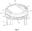
- FIG. 6 the end portion of a housing according to an embodiment of the invention is illustrated.
- a sill 27 around an outside portion of the wall of the housing 1 is shown, around which an end cap may be sealingly fitted.
- An upper portion of the housing wall is provided with apertures 20 which serve two purposes. On the one hand, these apertures serve to provide an anchoring means for the potting compound 12 , which secures the hollow fibers.
- some of the apertures serve as inlets into the filtration compartment on the outside surface of hollow fibers contained therein. The fluid may thereby be distributed into the compartment inflowing from the external port.
- Seal means 21 are shown in position corresponding to the positions of the respective housing outer walls and the inner walls separating the respective filtration compartments 2 and 3 .
- FIGS. 2 a and 5 a there is shown a possible embodiment of the filter device in which only the filtration compartment 2 intended for dialysate fluid flow in a blood filtration process is provided with liquid distribution apertures 20 at the ends of the compartment. Dialysis liquid may thereby flow first through fluid flow port 6 and to the outside of the filter membranes inside filtration chamber 2 via the peripheral channel 24 and the distribution apertures 20 and via the peripheral channel 24 .
- the ultrafiltration compartment 3 is provided with an external flow port 7 a on the wall of the housing 1 .
- the arrangement shown in FIGS. 2 a and 5 a avoids the potential need for an additional seal or wall component possibly requiring welding between the internal walls separating the respective chambers 172 , and 183 and the inside of the end cap 13 of the previously described embodiment.
- FIG. 6 the end portion of a tubular housing according to a possible embodiment of the invention is illustrated.
- a sill 27 around an outside portion of the wall of the housing 1 is shown, around which an end cap may be sealingly fitted.
- An upper portion of the housing wall is provided with apertures 20 which serve two purposes. On the one hand, these apertures serve to provide an anchoring means for the potting compound which secures the hollow fibers.
- some of the apertures serve as inlets into the filtration compartment on the outside surface of hollow fibers contained therein. The fluid is thereby distributed into the said compartment more evenly than by a local inflow at one external port only.
- Seal means 21 are shown in position corresponding to the positions of the respective housing outer walls and the inner walls separating the respective filtration compartments 2 and 3 .
- a filter device having three internal filtration compartments within a unitary housing 101 is illustrated.
- a first filter e.g. an ultrafiltration filter
- a compartment 103 located adjacent and between two outer, dialysis-type filtration compartments 102 , 104 .
- Fluid flow ports 106 and 107 allow fluid such as dialysis fluid to enter or leave filtration compartments communicating with a second surface of filter membranes provided therein.
- these are provided at a peripheral portion of an end cap 113 , although they could also be provided on the wall of the housing 101 (see the example of FIGS. 2 a and 5 a ).
- Distribution apertures 120 may be used to ensure anchoring of the potting compound (not shown) and allow inflow and outflow of fluids via an enclosed channel 124 as in the two compartment model described previously.
- fluid inflow and outflow means to the second surface of the filter membranes of the ultrafiltration compartment 103 may be provided molded integrally with the wall of the housing 101 .
- a conduit 119 may provide for infusion fluid emerging from compartment 103 via port 109 to flow into a header chamber within end cap 113 via inlet port 122 , where it is added to another fluid, e.g. blood passing across the first surfaces of filtration membranes in either or both of compartments 102 and 104 .
- FIGS. 9 , 9 a and 10 a three compartment device is shown in respective longitudinal section and in cross section.
- the internal compartments of the device are defined by two wall portions 148 and 149 joined at seam portions 35 . These define between them a central compartment 103 , and two outer compartments 102 and 104 .
- Some internal walls of the device are in parallel configuration in order to optimize the filling of the internal spaces with hollow fiber membranes. From FIG. 9 , 9 a it can be seen from arrow A that header chamber 117 within the upper end cap 113 may be configured such that the respective first surfaces of filter membrane means within compartments 102 and 104 can be disposed in fluid flow communication.
- the infusion fluid in the arrangement may be added to the blood via exit flow port 109 ( FIGS. 7 and 8 ), through conduit 119 ( FIGS. 7 and 8 ) and an additional inflow port 122 (shown in FIG. 7 ) in the header chamber 117 in an arrangement corresponding to a mid-dilution step.
- Flow port 115 is optional and may serve for fluid inflow or outflow or may serve to bleed air from the compartment 104 while it is being filled with e.g. blood or otherwise being primed, before being sealed again prior to the commencement of filtration.
- the wall members 130 and 131 may keep separate the dialysate flowing around channel 124 into or out of chambers 102 and 104 .
- the wall means could be replaced by an equivalent seal means (not shown).
- an infusion fluid may be passed into the flow port 125 ( FIG. 9 ) as indicated by arrow B.
- air may be let out through flow port 116 .
- the flow port 116 is may be sealed and purified infusion fluid (or other priming fluid which may be used) flows across the membrane means of the filtration compartment 103 emerging from a second surface of the membrane means through a fluid outlet 109 as shown in FIG. 7 .
- the fluid may be channeled into the header chamber 117 via conduit 119 already described.
- a second fluid usually blood
- Air may be bled from the chamber at port 115 (e.g., during priming or during use), before the blood flows across the header chamber 117 along the direction of arrow A and onto the first side of filter membrane means in compartment 102 before exiting along the direction of arrow D at flow port 126 .
- a conduit could be connected to fluid flow ports of whichever header chambers it may be desired to connect.
- Dialysis fluid may be passed into the compartments 104 and 102 via flow ports 107 and 111 respectively and may exit the compartments through ports 106 and 110 .
- fluid may be removed without addition of dialysis fluid, in which case corresponding inflow ports may be kept sealed.
- the device shown in FIG. 9 may be operated in a number of combinations of filtration processes described previously in this specification.
- FIGS. 11 , 11 a , 12 , 13 and 13 a various possibilities are shown for connecting together shell portions 41 , 42 , 141 , 142 of housing 1 , 101 .
- FIGS. 11 , 11 a and 12 show a possibility in which a two compartment housing 1 is formed from hinged housing shell sections 41 , 42 .
- Continuous wall means 8 consists of wall portions 48 and 49 .
- the wall means 8 could be made from a single wall portion either integral with one shell portion 41 or 42 or it could be fixed to the shell portions 41 , 42 using a bonding technique.
- Numeral 160 denotes fluid flow ports in general which may be inflow or outflow ports. In the FIGS.
- FIGS. 13 and 13 a show a similar housing 101 in two parts which are shell portions 141 and 142 . These are bonded or welded along laterally and longitudinally arranged seams 135 .
- the continuous wall portions 8 could be provided either from wall portions 148 and 149 or from a single portion attached to only one shell segment or added as a separate element.
- the respective portions may be held in an opened position as shown in FIG. 12 for filling with filter means such as hollow fiber bundles in each respective compartment of shell portion 41 or 141 before completing the housing 1 , 101 by closing shell portion 42 , 142 on top of said portion 41 in which filter means are laid longitudinally.
- the internal wall portions 48 , 49 , 148 , 148 may be welded together or bonded to thereby create internal walls 8 and to generate an integral filter housing.
- One method of welding includes laser welding as mentioned or welding using other electromagnetic means. The welding may be carried out while filter means such as membranes in the form of hollow fibers are in place within respective chambers in the housing.
- Materials used for the housing may advantageously include materials having particular light reflective properties in order to ensure an adequate weld.
- one of the housing sections may be made from substantially clear, uncolored material, while the other may contain a light-reflective dye suitable for causing plastics material at the boundary of the two housing portions to melt sufficiently to form a bond.
- one housing portion may be made from polycarbonate while another section may be made from polypropylene.
- the different refractive indices of the materials may produce sufficient heat for a weld to form when laser or electromagnetic radiation is aimed at the join or seam 35 , 135 .
Abstract
Description
Claims (16)
Priority Applications (2)
| Application Number | Priority Date | Filing Date | Title |
|---|---|---|---|
| US10/708,774 US7790029B2 (en) | 2003-04-11 | 2004-03-24 | Filter device having more than one filtration compartment |
| US11/736,310 US7622041B2 (en) | 2003-04-11 | 2007-04-17 | Method for making a filter device having more than one filtration compartment |
Applications Claiming Priority (5)
| Application Number | Priority Date | Filing Date | Title |
|---|---|---|---|
| US46255303P | 2003-04-11 | 2003-04-11 | |
| EP03008465A EP1466657B1 (en) | 2003-04-11 | 2003-04-11 | Filter device having more than one filtration compartment |
| EPEP03008465.1 | 2003-04-11 | ||
| EP03008465 | 2003-04-11 | ||
| US10/708,774 US7790029B2 (en) | 2003-04-11 | 2004-03-24 | Filter device having more than one filtration compartment |
Related Child Applications (1)
| Application Number | Title | Priority Date | Filing Date |
|---|---|---|---|
| US11/736,310 Division US7622041B2 (en) | 2003-04-11 | 2007-04-17 | Method for making a filter device having more than one filtration compartment |
Publications (2)
| Publication Number | Publication Date |
|---|---|
| US20040200768A1 US20040200768A1 (en) | 2004-10-14 |
| US7790029B2 true US7790029B2 (en) | 2010-09-07 |
Family
ID=32865008
Family Applications (2)
| Application Number | Title | Priority Date | Filing Date |
|---|---|---|---|
| US10/708,774 Active 2028-07-07 US7790029B2 (en) | 2003-04-11 | 2004-03-24 | Filter device having more than one filtration compartment |
| US11/736,310 Active 2024-06-02 US7622041B2 (en) | 2003-04-11 | 2007-04-17 | Method for making a filter device having more than one filtration compartment |
Family Applications After (1)
| Application Number | Title | Priority Date | Filing Date |
|---|---|---|---|
| US11/736,310 Active 2024-06-02 US7622041B2 (en) | 2003-04-11 | 2007-04-17 | Method for making a filter device having more than one filtration compartment |
Country Status (4)
| Country | Link |
|---|---|
| US (2) | US7790029B2 (en) |
| EP (1) | EP1466657B1 (en) |
| JP (1) | JP4659383B2 (en) |
| KR (1) | KR101131676B1 (en) |
Cited By (10)
| Publication number | Priority date | Publication date | Assignee | Title |
|---|---|---|---|---|
| DE102014201248A1 (en) * | 2014-01-23 | 2015-07-23 | Volkswagen Ag | Moisture exchanger and fuel cell assembly with such |
| US9328969B2 (en) | 2011-10-07 | 2016-05-03 | Outset Medical, Inc. | Heat exchange fluid purification for dialysis system |
| US9402945B2 (en) | 2014-04-29 | 2016-08-02 | Outset Medical, Inc. | Dialysis system and methods |
| US9545469B2 (en) | 2009-12-05 | 2017-01-17 | Outset Medical, Inc. | Dialysis system with ultrafiltration control |
| US10369263B2 (en) | 2014-03-29 | 2019-08-06 | Novaflux Inc. | Blood processing cartridges and systems, and methods for extracorporeal blood therapies |
| US10399040B2 (en) | 2015-09-24 | 2019-09-03 | Novaflux Inc. | Cartridges and systems for membrane-based therapies |
| US10426884B2 (en) | 2015-06-26 | 2019-10-01 | Novaflux Inc. | Cartridges and systems for outside-in flow in membrane-based therapies |
| US11534537B2 (en) | 2016-08-19 | 2022-12-27 | Outset Medical, Inc. | Peritoneal dialysis system and methods |
| US11724013B2 (en) | 2010-06-07 | 2023-08-15 | Outset Medical, Inc. | Fluid purification system |
| TWI824735B (en) * | 2022-09-22 | 2023-12-01 | 友達光電股份有限公司 | Light dispersion apparatus and hemodialysis system |
Families Citing this family (19)
| Publication number | Priority date | Publication date | Assignee | Title |
|---|---|---|---|---|
| US20070095741A1 (en) * | 2003-10-31 | 2007-05-03 | Berends Hendrik Johan F | Filter module |
| CA2543519C (en) * | 2003-11-07 | 2012-12-11 | Gambro Lundia Ab | End-cap assembly with pump hose for a filter and filter comprising such an end-cap assembly |
| DE602004017689D1 (en) | 2003-11-21 | 2008-12-24 | Samsung Electronics Co Ltd | Apparatus and method for generating coded block arrays for an alpha channel image and alpha channel coding and decoding apparatus and method. |
| WO2007009496A1 (en) * | 2005-07-22 | 2007-01-25 | Mahiout Arezki Ph D | Differential hemodialysis or hemodiafiltration |
| BRPI0916763B8 (en) * | 2008-07-15 | 2021-06-22 | Mirimedical Llc | dialyzer |
| CN102164647B (en) | 2008-09-24 | 2014-04-16 | 杰里·谢瓦利茨 | Screen filter module for alternating flow filtration |
| US9446354B2 (en) | 2010-08-25 | 2016-09-20 | Repligen Corporation | Device, system and process for modification or concentration of cell-depleted fluid |
| CN103210136B (en) | 2010-09-16 | 2016-04-06 | 三菱丽阳株式会社 | The manufacturing installation of the manufacture method of hollow fiber membrane tablet, the manufacture method of hollow fiber membrane module and hollow fiber membrane tablet |
| DE102011107980B4 (en) * | 2011-07-18 | 2017-11-02 | Fresenius Medical Care Deutschland Gmbh | Filter module, process for producing a hollow fiber membrane bundle, disposable and blood treatment device |
| HUE049097T2 (en) * | 2012-04-02 | 2020-09-28 | Mitsubishi Chem Corp | Hollow-fiber membrane module, and hollow-fiber membrane unit equipped with hollow-fiber membrane module |
| DE102013012674A1 (en) | 2013-07-31 | 2015-02-05 | Mann + Hummel Gmbh | Filter module with hollow fibers |
| JP7039477B2 (en) | 2015-11-10 | 2022-03-22 | レプリゲン・コーポレイション | Disposable filtration unit with alternating tangential flow |
| EP3178539A1 (en) * | 2015-12-11 | 2017-06-14 | Gambro Lundia AB | Filter device, system and method for filtration of fluids |
| WO2017205784A1 (en) | 2016-05-27 | 2017-11-30 | The Charles Stark Draper Laboratory, Inc. | Hemotransfiltration hollow fiber device |
| EP3415225B1 (en) | 2017-06-14 | 2021-03-03 | Gambro Lundia AB | System and method for filtration and/or dilation of fluids |
| KR102264517B1 (en) * | 2018-06-08 | 2021-06-11 | 코오롱인더스트리 주식회사 | Method of hollow fiber membrane module and hollow fiber membrane module using it |
| EP3842129B1 (en) * | 2019-12-24 | 2024-03-06 | Gambro Lundia AB | Sterile filter assembly |
| TW202206129A (en) * | 2020-07-01 | 2022-02-16 | 新加坡商阿瓦克科技私人有限公司 | A filter device for dialysis applications |
| DE102021121108A1 (en) | 2021-08-13 | 2023-02-16 | B.Braun Avitum Ag | Multipart dialyzer |
Citations (20)
| Publication number | Priority date | Publication date | Assignee | Title |
|---|---|---|---|---|
| FR2231421A1 (en) | 1973-05-30 | 1974-12-27 | Rhone Poulenc Sa | |
| US4211597A (en) | 1977-06-10 | 1980-07-08 | Cordis Dow Corp. | Method for making artificial kidney |
| US4226378A (en) * | 1976-02-13 | 1980-10-07 | Baxter Travenol Laboratories, Inc. | Method and apparatus for winding hollow filaments |
| US4341005A (en) * | 1980-11-06 | 1982-07-27 | Strimbeck, Davis & Soloway | Manufacture of hollow fiber fluid fractionating cells |
| US4343668A (en) | 1980-06-04 | 1982-08-10 | Hospal Sodip Sa | Method of producing bundles of hollow fibres potted at their ends |
| FR2506626A3 (en) | 1981-05-26 | 1982-12-03 | Inphardial Spa | Machine for dialysis and ultrafiltration - having two separate semi-permeable tube bundles operating separately or in parallel |
| DE3326704A1 (en) | 1983-07-23 | 1985-01-31 | Josef 6902 Sandhausen Magasi | Method and device for haemodialysis |
| EP0264695A2 (en) | 1986-10-11 | 1988-04-27 | Josef Magasi | Device and method for purifying blood |
| EP0305687A1 (en) | 1987-08-31 | 1989-03-08 | Gambro Dialysatoren GmbH & Co. KG | A diffusion and/or filtration apparatus and a method of manufacturing said apparatus |
| US4861485A (en) * | 1988-01-22 | 1989-08-29 | W. R. Grace & Co. | Hemodiafiltration device |
| EP0355325A1 (en) | 1988-07-07 | 1990-02-28 | GAMBRO DIALYSATOREN GMBH & CO. KG | A seal comprising a ring of a resilient material intended to be pressed between two parallel, preferably flat sealing surfaces |
| EP0525317A1 (en) | 1991-08-01 | 1993-02-03 | GAMBRO DIALYSATOREN GMBH & CO. KG | An apparatus for effecting mass and/or heat transfer |
| DE19607162A1 (en) | 1996-02-26 | 1997-09-04 | Fresenius Ag | Dialyzer |
| US5730712A (en) * | 1994-01-17 | 1998-03-24 | Althin Medical, Inc. | Extracorporeal blood treatment apparatus and method |
| EP0890368A1 (en) | 1997-07-09 | 1999-01-13 | SIS-TER S.p.A. | Blood treatment apparatus |
| US6074559A (en) | 1996-11-21 | 2000-06-13 | Fresenius Medical Care Deutschland Gmbh | Filter device having a hollow fiber bundle and associated sealing devices |
| WO2000044478A1 (en) | 1999-01-29 | 2000-08-03 | Gambro Dialysatoren Gmbh & Co Kg | Filters and method for producing filters |
| WO2001049399A1 (en) | 1999-12-30 | 2001-07-12 | Nephros, Inc. | Dual stage hemodiafiltration cartridge |
| WO2002047785A1 (en) | 2000-12-11 | 2002-06-20 | Nephros, Inc. | Hemodiafiltration / hemofiltration cartridges |
| US20030102264A1 (en) * | 2001-12-05 | 2003-06-05 | Pope Rodney William | Filtering device with associated sealing design and method |
Family Cites Families (1)
| Publication number | Priority date | Publication date | Assignee | Title |
|---|---|---|---|---|
| US6423223B1 (en) | 2000-08-31 | 2002-07-23 | Donald A. Northcut | Multi-element, reverse osmosis, liquid filter system with flushing and filtering circuits |
-
2003
- 2003-04-11 EP EP03008465A patent/EP1466657B1/en not_active Expired - Lifetime
-
2004
- 2004-03-24 US US10/708,774 patent/US7790029B2/en active Active
- 2004-04-12 JP JP2004116541A patent/JP4659383B2/en not_active Expired - Lifetime
- 2004-04-12 KR KR20040024808A patent/KR101131676B1/en active IP Right Grant
-
2007
- 2007-04-17 US US11/736,310 patent/US7622041B2/en active Active
Patent Citations (26)
| Publication number | Priority date | Publication date | Assignee | Title |
|---|---|---|---|---|
| FR2231421A1 (en) | 1973-05-30 | 1974-12-27 | Rhone Poulenc Sa | |
| US4038190A (en) | 1973-05-30 | 1977-07-26 | Rhone-Poulenc S.A. | Fluid fractionation apparatus and method of manufacturing the same |
| US4226378A (en) * | 1976-02-13 | 1980-10-07 | Baxter Travenol Laboratories, Inc. | Method and apparatus for winding hollow filaments |
| US4211597A (en) | 1977-06-10 | 1980-07-08 | Cordis Dow Corp. | Method for making artificial kidney |
| US4343668A (en) | 1980-06-04 | 1982-08-10 | Hospal Sodip Sa | Method of producing bundles of hollow fibres potted at their ends |
| US4341005A (en) * | 1980-11-06 | 1982-07-27 | Strimbeck, Davis & Soloway | Manufacture of hollow fiber fluid fractionating cells |
| FR2506626A3 (en) | 1981-05-26 | 1982-12-03 | Inphardial Spa | Machine for dialysis and ultrafiltration - having two separate semi-permeable tube bundles operating separately or in parallel |
| DE3326704A1 (en) | 1983-07-23 | 1985-01-31 | Josef 6902 Sandhausen Magasi | Method and device for haemodialysis |
| EP0264695A2 (en) | 1986-10-11 | 1988-04-27 | Josef Magasi | Device and method for purifying blood |
| EP0305687A1 (en) | 1987-08-31 | 1989-03-08 | Gambro Dialysatoren GmbH & Co. KG | A diffusion and/or filtration apparatus and a method of manufacturing said apparatus |
| US4861485A (en) * | 1988-01-22 | 1989-08-29 | W. R. Grace & Co. | Hemodiafiltration device |
| EP0355325A1 (en) | 1988-07-07 | 1990-02-28 | GAMBRO DIALYSATOREN GMBH & CO. KG | A seal comprising a ring of a resilient material intended to be pressed between two parallel, preferably flat sealing surfaces |
| EP0525317A1 (en) | 1991-08-01 | 1993-02-03 | GAMBRO DIALYSATOREN GMBH & CO. KG | An apparatus for effecting mass and/or heat transfer |
| US5730712A (en) * | 1994-01-17 | 1998-03-24 | Althin Medical, Inc. | Extracorporeal blood treatment apparatus and method |
| US5882516A (en) | 1996-02-26 | 1999-03-16 | Fresenius Ag | Dialyzer |
| DE19607162A1 (en) | 1996-02-26 | 1997-09-04 | Fresenius Ag | Dialyzer |
| US20020153314A1 (en) | 1996-11-21 | 2002-10-24 | Uwe Hahmann | Filter device |
| US6074559A (en) | 1996-11-21 | 2000-06-13 | Fresenius Medical Care Deutschland Gmbh | Filter device having a hollow fiber bundle and associated sealing devices |
| US6426002B1 (en) | 1996-11-21 | 2002-07-30 | Fresenius Medical Care Deutschland Gmbh | Filter device |
| EP0890368A1 (en) | 1997-07-09 | 1999-01-13 | SIS-TER S.p.A. | Blood treatment apparatus |
| WO2000044478A1 (en) | 1999-01-29 | 2000-08-03 | Gambro Dialysatoren Gmbh & Co Kg | Filters and method for producing filters |
| WO2001049399A1 (en) | 1999-12-30 | 2001-07-12 | Nephros, Inc. | Dual stage hemodiafiltration cartridge |
| WO2002047785A1 (en) | 2000-12-11 | 2002-06-20 | Nephros, Inc. | Hemodiafiltration / hemofiltration cartridges |
| US20040127842A1 (en) * | 2000-12-11 | 2004-07-01 | Collins Gregory R. | Hemodiafiltration/hemofiltration cartridges |
| US20030102264A1 (en) * | 2001-12-05 | 2003-06-05 | Pope Rodney William | Filtering device with associated sealing design and method |
| US6830685B2 (en) | 2001-12-05 | 2004-12-14 | Fresenius Usa, Inc. | Filtering device with associated sealing design and method |
Non-Patent Citations (1)
| Title |
|---|
| European Search Report, European Patent Office, issued Sep. 5, 2003 for European Application No. EP 03 00 8465, 4 pages. |
Cited By (17)
| Publication number | Priority date | Publication date | Assignee | Title |
|---|---|---|---|---|
| US9545469B2 (en) | 2009-12-05 | 2017-01-17 | Outset Medical, Inc. | Dialysis system with ultrafiltration control |
| US11724013B2 (en) | 2010-06-07 | 2023-08-15 | Outset Medical, Inc. | Fluid purification system |
| US9328969B2 (en) | 2011-10-07 | 2016-05-03 | Outset Medical, Inc. | Heat exchange fluid purification for dialysis system |
| DE102014201248A1 (en) * | 2014-01-23 | 2015-07-23 | Volkswagen Ag | Moisture exchanger and fuel cell assembly with such |
| US11446419B2 (en) | 2014-03-29 | 2022-09-20 | Novaflux Inc. | Blood processing cartridges and systems, and methods for extracorporeal blood therapies |
| US10369263B2 (en) | 2014-03-29 | 2019-08-06 | Novaflux Inc. | Blood processing cartridges and systems, and methods for extracorporeal blood therapies |
| US9402945B2 (en) | 2014-04-29 | 2016-08-02 | Outset Medical, Inc. | Dialysis system and methods |
| US9504777B2 (en) | 2014-04-29 | 2016-11-29 | Outset Medical, Inc. | Dialysis system and methods |
| US9579440B2 (en) | 2014-04-29 | 2017-02-28 | Outset Medical, Inc. | Dialysis system and methods |
| US11305040B2 (en) | 2014-04-29 | 2022-04-19 | Outset Medical, Inc. | Dialysis system and methods |
| US10426884B2 (en) | 2015-06-26 | 2019-10-01 | Novaflux Inc. | Cartridges and systems for outside-in flow in membrane-based therapies |
| US11648341B2 (en) | 2015-06-26 | 2023-05-16 | Novaflux Inc. | Cartridges and systems for outside-in flow in membrane-based therapies |
| US11701622B2 (en) | 2015-09-24 | 2023-07-18 | Novaflux Inc. | Cartridges and systems for membrane-based therapies |
| US10399040B2 (en) | 2015-09-24 | 2019-09-03 | Novaflux Inc. | Cartridges and systems for membrane-based therapies |
| US11534537B2 (en) | 2016-08-19 | 2022-12-27 | Outset Medical, Inc. | Peritoneal dialysis system and methods |
| US11951241B2 (en) | 2016-08-19 | 2024-04-09 | Outset Medical, Inc. | Peritoneal dialysis system and methods |
| TWI824735B (en) * | 2022-09-22 | 2023-12-01 | 友達光電股份有限公司 | Light dispersion apparatus and hemodialysis system |
Also Published As
| Publication number | Publication date |
|---|---|
| US20070181488A1 (en) | 2007-08-09 |
| EP1466657B1 (en) | 2012-10-03 |
| EP1466657A1 (en) | 2004-10-13 |
| US7622041B2 (en) | 2009-11-24 |
| US20040200768A1 (en) | 2004-10-14 |
| JP2004337845A (en) | 2004-12-02 |
| KR20040089559A (en) | 2004-10-21 |
| JP4659383B2 (en) | 2011-03-30 |
| KR101131676B1 (en) | 2012-03-28 |
Similar Documents
| Publication | Publication Date | Title |
|---|---|---|
| US7622041B2 (en) | Method for making a filter device having more than one filtration compartment | |
| JP4213384B2 (en) | Two-stage hemodiafiltration cartridge | |
| KR100649260B1 (en) | Dual-stage filtration cartridge | |
| JP2887347B2 (en) | Diffusion / filtration apparatus and method for manufacturing the same | |
| US5730712A (en) | Extracorporeal blood treatment apparatus and method | |
| KR100604460B1 (en) | Hemodiafiltration/hemofiltration cartridges | |
| JP2003265597A (en) | Hemodialysis filter and filtering device | |
| US10835868B2 (en) | Filter device, system and method for filtration of fluids | |
| US20210338910A1 (en) | Dialysis Device for Use with Interface Media, Dialysis Systems, Use of Dialysis Device, Method for Establishing Dialysis System, Method for Filling and/or Priming Dialysis System and Method for Removing Air from Dialysis System | |
| CN100518836C (en) | Diafiltration method | |
| EP3638406B1 (en) | System and method for filtration and/or dilution of fluids | |
| BG112033A (en) | Dialyzer |
Legal Events
| Date | Code | Title | Description |
|---|---|---|---|
| AS | Assignment |
Owner name: GAMBRO DIALYSATOREN GMBH & CO KG, GERMANY Free format text: ASSIGNMENT OF ASSIGNORS INTEREST;ASSIGNOR:PIRNER, MANFRED;REEL/FRAME:014444/0621 Effective date: 20030606 Owner name: GAMBRO DIALYSATOREN GMBH & CO KG, GERMANY Free format text: ASSIGNMENT OF ASSIGNORS INTEREST;ASSIGNORS:DANNENMEIER, JUERGEN;GOEHL, HERMANN;REEL/FRAME:014444/0619;SIGNING DATES FROM 20030606 TO 20030610 Owner name: GAMBRO LUNDIA AB, SWEDEN Free format text: ASSIGNMENT OF ASSIGNORS INTEREST;ASSIGNOR:GAMBRO DIALYSATOREN GMBH;REEL/FRAME:014444/0623 Effective date: 20030411 Owner name: GAMBRO DIALYSATOREN GMBH & CO KG, GERMANY Free format text: ASSIGNMENT OF ASSIGNORS INTEREST;ASSIGNORS:DANNENMEIER, JUERGEN;GOEHL, HERMANN;SIGNING DATES FROM 20030606 TO 20030610;REEL/FRAME:014444/0619 |
|
| AS | Assignment |
Owner name: CITICORP TRUSTEE COMPANY LIMITED, UNITED KINGDOM Free format text: IP SECURITY AGREEMENT SUPPLEMENT;ASSIGNOR:GAMBRO LUNDIA AB;REEL/FRAME:022714/0702 Effective date: 20090331 Owner name: CITICORP TRUSTEE COMPANY LIMITED,UNITED KINGDOM Free format text: IP SECURITY AGREEMENT SUPPLEMENT;ASSIGNOR:GAMBRO LUNDIA AB;REEL/FRAME:022714/0702 Effective date: 20090331 |
|
| STCF | Information on status: patent grant |
Free format text: PATENTED CASE |
|
| AS | Assignment |
Owner name: GAMBRO LUNDIA AB, COLORADO Free format text: RELEASE OF SECURITY INTEREST IN PATENTS;ASSIGNOR:CITICORP TRUSTEE COMPANY LIMITED, AS SECURITY AGENT;REEL/FRAME:027456/0050 Effective date: 20111207 |
|
| FPAY | Fee payment |
Year of fee payment: 4 |
|
| MAFP | Maintenance fee payment |
Free format text: PAYMENT OF MAINTENANCE FEE, 8TH YEAR, LARGE ENTITY (ORIGINAL EVENT CODE: M1552) Year of fee payment: 8 |
|
| MAFP | Maintenance fee payment |
Free format text: PAYMENT OF MAINTENANCE FEE, 12TH YEAR, LARGE ENTITY (ORIGINAL EVENT CODE: M1553); ENTITY STATUS OF PATENT OWNER: LARGE ENTITY Year of fee payment: 12 |