US7789037B2 - Device for the production of thin powder layers, in particular at high temperatures, during a method involving the use of a laser on a material - Google Patents
Device for the production of thin powder layers, in particular at high temperatures, during a method involving the use of a laser on a material Download PDFInfo
- Publication number
- US7789037B2 US7789037B2 US10/561,833 US56183304A US7789037B2 US 7789037 B2 US7789037 B2 US 7789037B2 US 56183304 A US56183304 A US 56183304A US 7789037 B2 US7789037 B2 US 7789037B2
- Authority
- US
- United States
- Prior art keywords
- powder
- cylinder
- enclosure
- deposition zone
- powder mixture
- Prior art date
- Legal status (The legal status is an assumption and is not a legal conclusion. Google has not performed a legal analysis and makes no representation as to the accuracy of the status listed.)
- Active, expires
Links
Images


Classifications
-
- B—PERFORMING OPERATIONS; TRANSPORTING
- B23—MACHINE TOOLS; METAL-WORKING NOT OTHERWISE PROVIDED FOR
- B23K—SOLDERING OR UNSOLDERING; WELDING; CLADDING OR PLATING BY SOLDERING OR WELDING; CUTTING BY APPLYING HEAT LOCALLY, e.g. FLAME CUTTING; WORKING BY LASER BEAM
- B23K26/00—Working by laser beam, e.g. welding, cutting or boring
- B23K26/34—Laser welding for purposes other than joining
-
- B—PERFORMING OPERATIONS; TRANSPORTING
- B22—CASTING; POWDER METALLURGY
- B22F—WORKING METALLIC POWDER; MANUFACTURE OF ARTICLES FROM METALLIC POWDER; MAKING METALLIC POWDER; APPARATUS OR DEVICES SPECIALLY ADAPTED FOR METALLIC POWDER
- B22F10/00—Additive manufacturing of workpieces or articles from metallic powder
- B22F10/20—Direct sintering or melting
- B22F10/28—Powder bed fusion, e.g. selective laser melting [SLM] or electron beam melting [EBM]
-
- B—PERFORMING OPERATIONS; TRANSPORTING
- B22—CASTING; POWDER METALLURGY
- B22F—WORKING METALLIC POWDER; MANUFACTURE OF ARTICLES FROM METALLIC POWDER; MAKING METALLIC POWDER; APPARATUS OR DEVICES SPECIALLY ADAPTED FOR METALLIC POWDER
- B22F12/00—Apparatus or devices specially adapted for additive manufacturing; Auxiliary means for additive manufacturing; Combinations of additive manufacturing apparatus or devices with other processing apparatus or devices
- B22F12/60—Planarisation devices; Compression devices
- B22F12/63—Rollers
-
- B—PERFORMING OPERATIONS; TRANSPORTING
- B22—CASTING; POWDER METALLURGY
- B22F—WORKING METALLIC POWDER; MANUFACTURE OF ARTICLES FROM METALLIC POWDER; MAKING METALLIC POWDER; APPARATUS OR DEVICES SPECIALLY ADAPTED FOR METALLIC POWDER
- B22F3/00—Manufacture of workpieces or articles from metallic powder characterised by the manner of compacting or sintering; Apparatus specially adapted therefor ; Presses and furnaces
- B22F3/004—Filling molds with powder
-
- B—PERFORMING OPERATIONS; TRANSPORTING
- B23—MACHINE TOOLS; METAL-WORKING NOT OTHERWISE PROVIDED FOR
- B23K—SOLDERING OR UNSOLDERING; WELDING; CLADDING OR PLATING BY SOLDERING OR WELDING; CUTTING BY APPLYING HEAT LOCALLY, e.g. FLAME CUTTING; WORKING BY LASER BEAM
- B23K35/00—Rods, electrodes, materials, or media, for use in soldering, welding, or cutting
- B23K35/02—Rods, electrodes, materials, or media, for use in soldering, welding, or cutting characterised by mechanical features, e.g. shape
- B23K35/0222—Rods, electrodes, materials, or media, for use in soldering, welding, or cutting characterised by mechanical features, e.g. shape for use in soldering, brazing
- B23K35/0244—Powders, particles or spheres; Preforms made therefrom
-
- B—PERFORMING OPERATIONS; TRANSPORTING
- B23—MACHINE TOOLS; METAL-WORKING NOT OTHERWISE PROVIDED FOR
- B23K—SOLDERING OR UNSOLDERING; WELDING; CLADDING OR PLATING BY SOLDERING OR WELDING; CUTTING BY APPLYING HEAT LOCALLY, e.g. FLAME CUTTING; WORKING BY LASER BEAM
- B23K35/00—Rods, electrodes, materials, or media, for use in soldering, welding, or cutting
- B23K35/02—Rods, electrodes, materials, or media, for use in soldering, welding, or cutting characterised by mechanical features, e.g. shape
- B23K35/0255—Rods, electrodes, materials, or media, for use in soldering, welding, or cutting characterised by mechanical features, e.g. shape for use in welding
-
- B—PERFORMING OPERATIONS; TRANSPORTING
- B29—WORKING OF PLASTICS; WORKING OF SUBSTANCES IN A PLASTIC STATE IN GENERAL
- B29C—SHAPING OR JOINING OF PLASTICS; SHAPING OF MATERIAL IN A PLASTIC STATE, NOT OTHERWISE PROVIDED FOR; AFTER-TREATMENT OF THE SHAPED PRODUCTS, e.g. REPAIRING
- B29C64/00—Additive manufacturing, i.e. manufacturing of three-dimensional [3D] objects by additive deposition, additive agglomeration or additive layering, e.g. by 3D printing, stereolithography or selective laser sintering
- B29C64/10—Processes of additive manufacturing
- B29C64/106—Processes of additive manufacturing using only liquids or viscous materials, e.g. depositing a continuous bead of viscous material
- B29C64/124—Processes of additive manufacturing using only liquids or viscous materials, e.g. depositing a continuous bead of viscous material using layers of liquid which are selectively solidified
- B29C64/129—Processes of additive manufacturing using only liquids or viscous materials, e.g. depositing a continuous bead of viscous material using layers of liquid which are selectively solidified characterised by the energy source therefor, e.g. by global irradiation combined with a mask
- B29C64/135—Processes of additive manufacturing using only liquids or viscous materials, e.g. depositing a continuous bead of viscous material using layers of liquid which are selectively solidified characterised by the energy source therefor, e.g. by global irradiation combined with a mask the energy source being concentrated, e.g. scanning lasers or focused light sources
-
- B—PERFORMING OPERATIONS; TRANSPORTING
- B22—CASTING; POWDER METALLURGY
- B22F—WORKING METALLIC POWDER; MANUFACTURE OF ARTICLES FROM METALLIC POWDER; MAKING METALLIC POWDER; APPARATUS OR DEVICES SPECIALLY ADAPTED FOR METALLIC POWDER
- B22F12/00—Apparatus or devices specially adapted for additive manufacturing; Auxiliary means for additive manufacturing; Combinations of additive manufacturing apparatus or devices with other processing apparatus or devices
- B22F12/22—Driving means
- B22F12/224—Driving means for motion along a direction within the plane of a layer
-
- B—PERFORMING OPERATIONS; TRANSPORTING
- B22—CASTING; POWDER METALLURGY
- B22F—WORKING METALLIC POWDER; MANUFACTURE OF ARTICLES FROM METALLIC POWDER; MAKING METALLIC POWDER; APPARATUS OR DEVICES SPECIALLY ADAPTED FOR METALLIC POWDER
- B22F12/00—Apparatus or devices specially adapted for additive manufacturing; Auxiliary means for additive manufacturing; Combinations of additive manufacturing apparatus or devices with other processing apparatus or devices
- B22F12/22—Driving means
- B22F12/226—Driving means for rotary motion
-
- B—PERFORMING OPERATIONS; TRANSPORTING
- B22—CASTING; POWDER METALLURGY
- B22F—WORKING METALLIC POWDER; MANUFACTURE OF ARTICLES FROM METALLIC POWDER; MAKING METALLIC POWDER; APPARATUS OR DEVICES SPECIALLY ADAPTED FOR METALLIC POWDER
- B22F12/00—Apparatus or devices specially adapted for additive manufacturing; Auxiliary means for additive manufacturing; Combinations of additive manufacturing apparatus or devices with other processing apparatus or devices
- B22F12/50—Means for feeding of material, e.g. heads
-
- B—PERFORMING OPERATIONS; TRANSPORTING
- B22—CASTING; POWDER METALLURGY
- B22F—WORKING METALLIC POWDER; MANUFACTURE OF ARTICLES FROM METALLIC POWDER; MAKING METALLIC POWDER; APPARATUS OR DEVICES SPECIALLY ADAPTED FOR METALLIC POWDER
- B22F12/00—Apparatus or devices specially adapted for additive manufacturing; Auxiliary means for additive manufacturing; Combinations of additive manufacturing apparatus or devices with other processing apparatus or devices
- B22F12/60—Planarisation devices; Compression devices
- B22F12/67—Blades
-
- B—PERFORMING OPERATIONS; TRANSPORTING
- B22—CASTING; POWDER METALLURGY
- B22F—WORKING METALLIC POWDER; MANUFACTURE OF ARTICLES FROM METALLIC POWDER; MAKING METALLIC POWDER; APPARATUS OR DEVICES SPECIALLY ADAPTED FOR METALLIC POWDER
- B22F2999/00—Aspects linked to processes or compositions used in powder metallurgy
-
- B—PERFORMING OPERATIONS; TRANSPORTING
- B23—MACHINE TOOLS; METAL-WORKING NOT OTHERWISE PROVIDED FOR
- B23K—SOLDERING OR UNSOLDERING; WELDING; CLADDING OR PLATING BY SOLDERING OR WELDING; CUTTING BY APPLYING HEAT LOCALLY, e.g. FLAME CUTTING; WORKING BY LASER BEAM
- B23K2101/00—Articles made by soldering, welding or cutting
- B23K2101/04—Tubular or hollow articles
-
- Y—GENERAL TAGGING OF NEW TECHNOLOGICAL DEVELOPMENTS; GENERAL TAGGING OF CROSS-SECTIONAL TECHNOLOGIES SPANNING OVER SEVERAL SECTIONS OF THE IPC; TECHNICAL SUBJECTS COVERED BY FORMER USPC CROSS-REFERENCE ART COLLECTIONS [XRACs] AND DIGESTS
- Y02—TECHNOLOGIES OR APPLICATIONS FOR MITIGATION OR ADAPTATION AGAINST CLIMATE CHANGE
- Y02P—CLIMATE CHANGE MITIGATION TECHNOLOGIES IN THE PRODUCTION OR PROCESSING OF GOODS
- Y02P10/00—Technologies related to metal processing
- Y02P10/25—Process efficiency
Definitions
- the invention relates to a device for making thin layers of a powder or a mixture of powders, and more particularly making thin layers of ceramic or metallic powder or of a mixture of ceramic or metallic powders, for use in a process based on the action of a laser on a material contained in a thermal enclosure, in particular in a process of sintering by means of a laser beam.
- WO-A-99/42421 discloses a fast prototyping method based on using a laser to perform solid phase sintering of a powder or of a mixture of powders. For that purpose, use is made of an oven heated to 900° C., together with a commercially-available ceramic or metallic powder or a mixture of ceramic or metallic powders of any grain size or distribution.
- a work plane is provided with two wells, the first forming a supply from which the powder or powder mixture is taken, and transferred to over the second well where it is spread in thin layers, prior to being sintered using a laser beam.
- the powder or powder mixture is transported between the two wells by a device described in WO-A-01/41939. That device is guided in translation and movable in rotation.
- the scraper formed in this way moves at a given angle relative to the work plane, thereby compressing the powder partially thereagainst.
- the scraper is connected to a roller that is free to rotate and that is driven in translation by its own weight.
- the roller acts behind the scraper and compacts the powder or powder mixture.
- the scraper and the roller move in a work plane provided with guide rails, and studs on the flanks of the rails which thus enable the scraper to be tilted at the end of its stroke.
- such a device When using arbitrary powders or powder mixtures, such a device does not make it possible in reliable manner to obtain a thickness, a surface quality, and a shape as desired for the layer deposited in that way. Furthermore, in an atmosphere that may be at a temperature that can reach 900° C., it is difficult to use such a device for making layers. After a few passes, an abrasion and wear phenomenon appears on the various parts situated in the enclosure. The abrasion and the wear spoil the uniformity of the layers as deposited in that way. In addition, those two members are guided inside the thermal enclosure. Insofar as the enclosure is subjected to a temperature that can be as high as 900° C., the means for guiding the scraper and the roller are subject to expansion. They do not necessarily expand by the same amounts, thereby degrading the accuracy with which the powder or powder mixture is laid out in layers. Furthermore, driving the roller under its own weight does not make it any easier for it to be guided in regular and accurate manner.
- such a device for laying powder in layers comprises two distinct elements, the scraper and the compacting roller, and the total bulk thereof requires the work plane and the enclosure to be of considerable length.
- This dimensioning of the apparatus, and in particular of the enclosure does not make it easy to regulate temperature within the enclosure. It thus frequently happens that a temperature gradient arises, thereby accentuating the previously-observed expansion differences between the scraper and the roller.
- U.S. Pat. No. 5,252,264 discloses apparatus fitted with a roller having an outside surface that is rough. Thus, the powder is held in position in the indentations of the roller. A blade can be used for dislodging the powder. With such apparatus, the retention of powder on the roller and the deposition of powder are unsuitable for laying thin layers with all types of powder.
- the invention seeks more particularly to remedy those drawbacks by proposing a device enabling powder or powder mixtures to be laid in thin and uniform layers having a minimum thickness of about 5 ⁇ m, and capable of doing this at high temperatures of up to about 1200° C., while ensuring that the layers are of the quality needed for a laser to act on the material, and while making it possible to avoid the consequences of a temperature gradient and the effects of abrasion on the means for laying the layers.
- the invention provides a device for laying at least one thin layer of a powder or powder mixture, the device being used to enable a laser to act on the material contained in a thermal enclosure, the device comprising storage means, powder or powder mixture feeder means, a deposition zone for depositing said powder or powder mixture taken from said storage means, and means for compacting the powder or powder mixture deposited in said deposition zone, the device being characterized in that it comprises a circular cylinder provided firstly with at least one groove formed in an outside surface of said cylinder and adapted to feed powder or powder mixture from a storage means and feed it to a deposition zone, and secondly with a surface adapted to compact the powder or powder mixture previously deposited on said deposition zone, said cylinder, said storage means, said deposition zone, and the powder or powder mixture being situated inside said enclosure that is suitable for being maintained at high temperature while enabling the cylinder to be guided and driven from outside said enclosure.
- a device that uses the same means to perform the functions both of feeding and of compacting inside an enclosure that is maintained at high temperature, and that does so in a manner that is coordinated.
- a device enables the device to be guided accurately and constantly, thereby guaranteeing that the layers are laid uniformly, even when the layers are thin.
- the small size of such a device also makes it possible to overcome different dimensional differences between the feeder means and the compactor means as can be generated by the thermal gradient that exists between different zones of an enclosure.
- the use of a feed groove enables powder to be deposited in optimized manner, while the compactor surface can have a surface state that is adapted to its function.
- a single member enables powder to be taken, deposited, and compacted.
- the device incorporates one or more of the following characteristics:
- FIG. 1 is a fragmentary section of a device in accordance with the invention, in which only the portion comprising the storage means, the deposition zone, and the member for laying the layers are shown, the member for laying the layers being shown in section, inside a closed enclosure, in the position for depositing powder over the deposition zone, the guide system outside the enclosure not being shown;
- FIG. 2 is a section of the device shown in the preceding figure, the member for laying the layers being shown in a face view looking along arrow F in FIG. 1 ;
- FIG. 3 is a perspective view of a portion of the layer-laying member on its own
- FIG. 3A is a section on plane III A of FIG. 3 ;
- FIGS. 4A to 4G are diagrams showing various stages in taking powder from the storage means, depositing the powder, spreading the powder, and compacting it on the deposition zone;
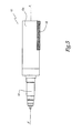
- FIG. 5 is a fragmentary diagrammatic view of a layer-laying member in another embodiment.
- FIG. 6 is a section on line VI-VI of FIG. 2 , in which the layer-laying member and the guide and drive elements are not shown.
- the device 1 shown in FIG. 1 comprises a thermally-insulated enclosure provided in its top portion with heater means (not shown).
- the enclosure is supported by a stationary structure and comprises a bottom 2 generally configured in the shape of a hollow rectangular parallelepiped having a cover 3 placed thereon.
- a window 4 e.g. made of silica, is formed in the cover 3 .
- the window 4 serves to pass a laser beam while it is acting on a powder or powder mixture.
- the bottom 2 is stationary and secured to the support structure of the device 1 .
- the cover 3 is guided horizontally in such a manner as to release full access to the inside volume of the bottom 2 .
- the bottom 2 presents a plane inside face 5 provided in one portion with two circular orifices 6 and 7 corresponding to the openings of two wells formed in the device 1 .
- a piston 8 or 9 moves in a direction that is generally perpendicular to the plane B in which the longitudinal axis AA′ of the layer-laying member is moved, each piston serving to close the corresponding orifice 6 or 7 temporarily.
- the face 5 forms a continuous work plane.
- the pistons 8 and 9 seal the wells and prevent powder or gas present in the enclosure from passing into the wells.
- the pistons 8 and 9 are moved between the corresponding orifices 6 or 7 and the inside of respective circular-based cylindrical wells 10 or 11 extending the orifices 6 and 7 respectively.
- the pistons 8 and 9 are moved independently of each other, each being actuated by a drive system, in particular by a stepper motor, by a precision screw and ball nut system, or by any other drive device. When they move, the pistons are guided by guide means such as guide elements with pre-stressed balls, for example. The guide device is not subjected to the thermal stresses encountered in the device 1 .
- the pistons 8 and 9 are moved with precision between the bottoms of the wells 10 and 11 and the orifices 6 and 7 . For each piston, the precision obtained is about plus or minus one micron on the thickness of a deposited layer of powder.
- the top face of the piston 8 situated in the well 10 forms the bottom of a reserve in which a ceramic or metallic powder P or a mixture of ceramic or metallic powders is stored.
- the orifice 7 into which the piston 9 penetrates on moving inside the well 11 is situated generally vertically beneath the window 4 when the cover 3 is closed.
- the piston 9 carries a tray 90 which forms the deposition zone on which the powder P or powder mixture is deposited in thin layers prior to the laser acting on the material.
- the tray 90 is positioned removably in the well 11 , thus enabling the part to be transported, once it has been made, without it being necessary to handle the part directly.
- the tray 90 is positioned precisely on the piston 9 so as to ensure that the first layer of powder or powder mixture is laid accurately. This first layer serves to hold and position the part that is to be made and determines the quality of the following layers.
- the stroke of the pistons 8 and 9 is adapted so that the piston 8 and the tray 90 come flush with the face 5 when the pistons are at their respective top dead-center positions.
- a drive and guide system (not shown) serves to move in rotation and in translation a member 12 for feeding and compacting the powder P or powder mixture between the pistons 8 and 9 .
- the guide system is adapted to guide the bottom 2 from the outside, while maintaining the enclosure thermally insulated. This guidance from the outside makes it possible to avoid the thermal and mechanical constraints that are encountered inside the enclosure.
- the member 12 is a part that is preferably made of ceramic material. With such a material, and having appropriate shape and dimensions, the member 12 possesses a high degree of dimensional and geometrical stability ensuring that it is not subjected to deformation when the enclosure is heated to high temperature, e.g. to about 1200° C. Similarly, the member 12 provides a high degree of resistance to abrasion.
- the member 12 is in the form of a circular cylinder provided at each of its ends in a central position with a respective stub axle 13 , 14 extending along the longitudinal axis AA′ of the cylinder.
- These stub axles 13 , 14 project outside the bottom 2 by passing through its side walls, and on the outside they are associated with a motor-driven drive and guide device.
- the surface state of the outside surface 12 a of the cylinder is of a quality that is close to “mirror polish”, or that is at least as smooth as the surface state of the deposition zone 9 .
- the surface 12 a presents roughness Ra that is less than or equal to 0.06 ⁇ m.
- Thermal isolation between the inside of the enclosure and the outside guide and drive means is provided by a combination of flaps 20 and 21 of simple geometrical shape, in particular of triangular shape and of parallelogram shape, respectively.
- flaps 20 , 21 are placed in alternation on either side of the enclosure in such a manner as to constitute a baffle.
- the flaps are in simple mechanical contact, which means that between them they operate without friction and without wear.
- the flaps 20 of right-angled triangular shape are associated in such a manner as to form a rectangle, and they can be moved back and forth in a direction that is substantially parallel to the displacement of the pistons 8 and 9 .
- the flaps 21 of parallelogram shape are movable in a direction that is generally perpendicular to the displacement of the pistons 8 and 9 . In this way, the baffle constituted by the flaps 20 and 21 ensures that the enclosure remains isolated.
- the overall size of the device is also kept small.
- the cylinder 12 is put accurately into motion so as to move in the plane B over the face 5 along a stroke that is adapted to enable it to pass in succession over both of the wells 10 and 11 .
- the parameters for servo-controlling the cylinder 12 e.g. its position and its speed of rotation, are defined as a function of the powder or powder mixture, of the thickness of the layer to be laid, and of other working parameters, such as temperature, for example.
- the cylinder 12 On its cylindrical outside surface, the cylinder 12 presents a longitudinal groove 15 .
- This groove 15 extends in a direction that is generally parallel to the longitudinal axis AA′ of the cylinder 12 .
- the groove 15 is of generally V-shaped section, having one wall 15 a that slopes relative to a plane P 15 of the groove 15 .
- the walls 15 a and 15 b converge towards the bottom 15 c of the groove 15 .
- One of the walls 15 b of the groove is terminated by an edge 16 where the plane P 15 intersects the outside cylindrical surface 12 a of the cylinder 12 .
- the edge 16 forms a scraper suitable for collecting the powder P or powder mixture on the piston 8 , and for directing the powder or powder mixture towards the bottom 15 c of the groove 15 .
- the circumference of the cylinder 12 is adapted so that when it forms one complete revolution about its axis AA′, it moves through a distance that is sufficient to cover the entire surface of either one of the orifices 6 or 7 .
- the angle of inclination of the inside wall 15 b of the groove 15 is adapted so as to ensure that powder or powder mixture is taken effectively when the cylinder 12 moves over the piston 8 , while subsequently ensuring that the powder P is deposited completely and quickly on the tray 90 .
- the cylinder 12 is in a rest position at one end of the face 5 , with the groove 15 being empty.
- the powder P or powder mixture is stored on the piston 8 , with the piston being in a position that is high enough to ensure that the powder P or powder mixture projects slightly above the face 5 .
- the tray 90 is positioned to lie in its orifice 7 flush with the face 5 .
- the cylinder 12 is caused to turn R 2 so as to position a generator line 17 of its cylindrical surface 12 a above the tray 90 .
- the powder P can be distributed uniformly and easily on the tray 90 , e.g. by moving the cylinder in translation F 1 with the generator line 17 acting like a scraper to spread the powder on the tray 90 .
- a portion 16 a of the cylindrical surface 12 a of the cylinder, generally situated between the generator line 17 and the edge 16 also contributes to spreading the powder.
- the piston 9 is moved towards the orifice 7 so that the gap between the tray 90 or the previously-deposited layer and the cylinder 12 is generally equal to the thickness of the spread layer of powder prior to being compacted.
- intermediate thickness are set for the layers.
- This direction of rotation R 2 is opposite to the direction of rotation R 1 and serves to return the cylinder 12 along arrow F 2 towards its initial position, as shown in FIG. 4G .
- the piston 8 and the tray 90 move so as to define a gap relative to the cylinder 12 that corresponds to the final thickness of the layer.
- the cylinder 12 passes over the tray 90 in the opposite direction, thereby smoothing and compacting the powder P by means of the outside surface 12 a of the cylinder 12 .
- the fact that the surface state of the surface 12 a is close to a mirror polish, means that it is possible to deposit and then compact a powder P regardless of the nature and/or the grain size of the powder.
- the surface 16 a also contributes to smoothing.
- the circumference of the cylinder 12 is greater than the diameter of the tray 90 . If necessary, the compacting operation can be repeated until a desired thickness has been obtained.
- the piston 9 and the tray 90 are moved in direction F 4 or F′ 4 , while the cylinder 12 is performing the movement R 2 , F 2 .
- the layer of powder or powder mixture as spread in this way can then be subjected to the action of a laser beam, e.g. in a sintering or fusing process, with all of the operations taking place in the enclosure which is maintained at high temperature and kept gastight.
- the powder or powder mixture is laid in layers at ambient temperature, e.g. while the enclosure is open.
- the tray 90 of thickness that may be as little as 5 ⁇ m, depending on the grain size of the powder P used, ready for action by a laser on the powder.
- a cylinder 12 with a scraper that is not formed by an edge 16 of the groove 15 , but by a fitting 18 fitted to an edge of the groove 15 .
- This fitting 18 is secured in definitive manner, e.g. by welding or by screw-fastening.
- Such a device for laying thin layers can thus be used in a confined atmosphere, i.e. while the cover 3 is closed, optionally at high temperatures or very high temperatures, or in ambient air, particularly if that is possible given the grain size and the nature of the powder. When operating in ambient air the cover 3 remains open.
- the guide means, both for the cylinder 12 and for the pistons 8 and 9 are located outside the working enclosure and the sealing and thermal isolation means protect them from the powder and the high temperature, if any.
- the shape of the groove 15 may be different from that shown.
- a groove 15 could be formed over a fraction only of the length of the cylinder 12 .
Abstract
Description
-
- The surface adapted for compacting comprises at least a fraction of an outside surface of said cylinder in which at least one groove is formed.
- The groove extends between the two ends of the cylinder in a direction that is generally parallel to the longitudinal axis of the member.
- The groove presents a cross-section that is generally in the configuration of a flat-bottomed V-shape.
- The circumference of the cylinder is perceptibly greater than the diameter of the deposition zone.
- The roughness of the outside surface of the cylinder is smaller than the roughness of the surface of the deposition zone, the roughness of the outside surface of the cylinder being adapted to the minimum grain size of the powder.
- The temperature at which the enclosure and the elements situated therein are maintained lies between ambient temperature and about 1200° C.
- The positioning, guiding, and driving of the cylinder are performed by positioning and guidance members, and by an actuator situated outside the enclosure of the device.
- Flaps disposed in the flanks of the enclosure are movable in different directions relative to a plane in which the longitudinal axis of the cylinder moves when the cylinder is moved. Advantageously, these flaps are triangle- and parallelogram-shaped, being disposed as a baffle and in mutual contact, so as to provide thermal insulation for the enclosure while enabling the cylinder to be connected to the members for positioning, guiding, and driving the cylinder.
y=(ax+b)/(cx+d)
Claims (10)
Applications Claiming Priority (4)
| Application Number | Priority Date | Filing Date | Title |
|---|---|---|---|
| FR0307888A FR2856614B1 (en) | 2003-06-30 | 2003-06-30 | DEVICE FOR PRODUCING THIN LAYERS OF POWDER, PARTICULARLY AT HIGH TEMPERATURES, IN A PROCESS BASED ON THE ACTION OF A LASER ON THE MATERIAL |
| FR0307888 | 2003-06-30 | ||
| FR03/07888 | 2003-06-30 | ||
| PCT/FR2004/001646 WO2005002764A1 (en) | 2003-06-30 | 2004-06-28 | Device for the production of thin powder layers, in particular at high temperatures, during a method involving the use of a laser on a material |
Publications (2)
| Publication Number | Publication Date |
|---|---|
| US20070245950A1 US20070245950A1 (en) | 2007-10-25 |
| US7789037B2 true US7789037B2 (en) | 2010-09-07 |
Family
ID=33515521
Family Applications (1)
| Application Number | Title | Priority Date | Filing Date |
|---|---|---|---|
| US10/561,833 Active 2026-10-07 US7789037B2 (en) | 2003-06-30 | 2004-06-28 | Device for the production of thin powder layers, in particular at high temperatures, during a method involving the use of a laser on a material |
Country Status (10)
| Country | Link |
|---|---|
| US (1) | US7789037B2 (en) |
| EP (1) | EP1641580B1 (en) |
| JP (1) | JP4778895B2 (en) |
| AT (1) | ATE397988T1 (en) |
| DE (1) | DE602004014376D1 (en) |
| DK (1) | DK1641580T3 (en) |
| ES (1) | ES2308232T3 (en) |
| FR (1) | FR2856614B1 (en) |
| PL (1) | PL1641580T3 (en) |
| WO (1) | WO2005002764A1 (en) |
Cited By (29)
| Publication number | Priority date | Publication date | Assignee | Title |
|---|---|---|---|---|
| RU2487779C1 (en) * | 2012-05-11 | 2013-07-20 | Открытое акционерное общество "Национальный институт авиационных технологий" (ОАО НИАТ) | Plant for making parts by layer-by-layer synthesis |
| US9254535B2 (en) | 2014-06-20 | 2016-02-09 | Velo3D, Inc. | Apparatuses, systems and methods for three-dimensional printing |
| US9327451B2 (en) | 2011-04-19 | 2016-05-03 | Phenix Systems | Method for manufacturing an object by solidifying a powder using a laser |
| US9662840B1 (en) | 2015-11-06 | 2017-05-30 | Velo3D, Inc. | Adept three-dimensional printing |
| US9919360B2 (en) | 2016-02-18 | 2018-03-20 | Velo3D, Inc. | Accurate three-dimensional printing |
| US9950392B2 (en) | 2014-03-04 | 2018-04-24 | Rohr, Inc. | Forming one or more apertures in a fiber-reinforced composite object with a laser |
| US9962767B2 (en) | 2015-12-10 | 2018-05-08 | Velo3D, Inc. | Apparatuses for three-dimensional printing |
| US20180126649A1 (en) | 2016-11-07 | 2018-05-10 | Velo3D, Inc. | Gas flow in three-dimensional printing |
| US10144176B1 (en) | 2018-01-15 | 2018-12-04 | Velo3D, Inc. | Three-dimensional printing systems and methods of their use |
| US10252336B2 (en) | 2016-06-29 | 2019-04-09 | Velo3D, Inc. | Three-dimensional printing and three-dimensional printers |
| US10272525B1 (en) | 2017-12-27 | 2019-04-30 | Velo3D, Inc. | Three-dimensional printing systems and methods of their use |
| US10315252B2 (en) | 2017-03-02 | 2019-06-11 | Velo3D, Inc. | Three-dimensional printing of three-dimensional objects |
| US10449696B2 (en) | 2017-03-28 | 2019-10-22 | Velo3D, Inc. | Material manipulation in three-dimensional printing |
| US10569364B2 (en) | 2017-01-06 | 2020-02-25 | General Electric Company | Systems and methods for additive manufacturing recoating |
| US10576543B2 (en) | 2014-01-24 | 2020-03-03 | United Technologies Corporation | Alloying metal materials together during additive manufacturing or one or more parts |
| US10611092B2 (en) | 2017-01-05 | 2020-04-07 | Velo3D, Inc. | Optics in three-dimensional printing |
| US10751940B2 (en) | 2016-10-27 | 2020-08-25 | Hewlett-Packard Development Company, L.P. | Recoater for 3D printers |
| US10807165B2 (en) | 2014-01-24 | 2020-10-20 | Raytheon Technologies Corporation | Conditioning one or more additive manufactured objects |
| US10807308B2 (en) | 2011-12-20 | 2020-10-20 | Compagnie Generale Des Etablissements Michelin | Machine and process for powder-based additive manufacturing |
| US10913129B2 (en) | 2014-01-24 | 2021-02-09 | Raytheon Technologies Corporation | Additive manufacturing an object from material with a selective diffusion barrier |
| US11033961B2 (en) | 2014-01-09 | 2021-06-15 | Raytheon Technologies Corporation | Material and processes for additively manufacturing one or more parts |
| US11072026B2 (en) | 2014-01-14 | 2021-07-27 | Raytheon Technologies Corporation | Systems and processes for distributing material during additive manufacturing |
| RU208175U1 (en) * | 2021-08-10 | 2021-12-07 | Федеральное государственное бюджетное образовательное учреждение высшего образования "Московский государственный технологический университет "СТАНКИН" (ФГБОУ ВО "МГТУ" СТАНКИН") | A device for obtaining products from polymers by layer-by-layer synthesis |
| US11225016B2 (en) * | 2017-10-20 | 2022-01-18 | Hewlett-Packard Development Company, L.P. | Additive manufacturing layers |
| US11235392B2 (en) | 2014-01-24 | 2022-02-01 | Raytheon Technologies Corporation | Monitoring material soldification byproducts during additive manufacturing |
| RU2773558C1 (en) * | 2021-08-10 | 2022-06-06 | Федеральное государственное бюджетное образовательное учреждение высшего образования "Московский государственный технологический университет "СТАНКИН" (ФГБОУ ВО "МГТУ "СТАНКИН") | Device for selective laser sintering of products made of powdered polymer materials |
| US11691343B2 (en) | 2016-06-29 | 2023-07-04 | Velo3D, Inc. | Three-dimensional printing and three-dimensional printers |
| WO2023211317A1 (en) * | 2022-04-29 | 2023-11-02 | Общество с ограниченной ответственностью "АВП Инновации" | Method for additively manufacturing irregularly shaped articles |
| EP3233337B1 (en) * | 2014-12-18 | 2023-12-06 | Compagnie Générale des Etablissements Michelin | Laser sintering method for manufacturing a tread molding element |
Families Citing this family (30)
| Publication number | Priority date | Publication date | Assignee | Title |
|---|---|---|---|---|
| KR101307509B1 (en) * | 2005-05-11 | 2013-09-12 | 아르켐 에이비 | Powder application system |
| DE102006023484A1 (en) | 2006-05-18 | 2007-11-22 | Eos Gmbh Electro Optical Systems | Apparatus and method for layering a three-dimensional object from a powdery building material |
| JP4882868B2 (en) * | 2007-05-24 | 2012-02-22 | パナソニック電工株式会社 | Manufacturing method of three-dimensional shaped object |
| FR2948044B1 (en) | 2009-07-15 | 2014-02-14 | Phenix Systems | THIN-LAYERING DEVICE AND METHOD OF USING SUCH A DEVICE |
| FR2949988B1 (en) | 2009-09-17 | 2011-10-07 | Phenix Systems | PROCESS FOR PRODUCING AN OBJECT BY LASER TREATMENT FROM AT LEAST TWO DIFFERENT PULVERULENT MATERIALS AND CORRESPONDING INSTALLATION |
| DE102010006939A1 (en) | 2010-02-04 | 2011-08-04 | Voxeljet Technology GmbH, 86167 | Device for producing three-dimensional models |
| GB201014950D0 (en) | 2010-09-08 | 2010-10-20 | Johnson Matthey Plc | Catalyst manufacturing method |
| DE102011007957A1 (en) | 2011-01-05 | 2012-07-05 | Voxeljet Technology Gmbh | Device and method for constructing a layer body with at least one body limiting the construction field and adjustable in terms of its position |
| FR2975319B1 (en) | 2011-05-17 | 2014-04-11 | Michelin Soc Tech | METHOD FOR MANUFACTURING LASER SINTER MOLDING ELEMENT |
| FR2991208B1 (en) | 2012-06-01 | 2014-06-06 | Michelin & Cie | MACHINE AND PROCESS FOR ADDITIVE MANUFACTURE OF POWDER |
| FR2996800B1 (en) | 2012-10-17 | 2014-11-14 | Michelin & Cie | MOLDING ELEMENT FOR A TIRE MOLD COMPRISING A POROUS ZONE |
| FR3002167B1 (en) | 2013-02-15 | 2016-12-23 | Michelin & Cie | PIECE OBTAINED BY SELECTIVE FUSION OF A POWDER COMPRISING A MAIN ELEMENT AND RIGID SECONDARY ELEMENTS |
| FR3002168B1 (en) | 2013-02-15 | 2016-12-23 | Michelin & Cie | PIECE OBTAINED BY SELECTIVE FUSION OF A POWDER COMPRISING A MAIN ELEMENT AND RIGID SECONDARY ELEMENTS |
| FR3014338B1 (en) | 2013-12-05 | 2015-12-18 | Michelin & Cie | MACHINE AND PROCESS FOR ADDITIVE MANUFACTURE OF POWDER |
| FR3018223B1 (en) | 2014-03-10 | 2017-11-03 | Michelin & Cie | PNEUMATIC COMPRISING A HIGH CONTRAST TEXTURE IN A GROOVE |
| FR3018224B1 (en) | 2014-03-10 | 2017-11-17 | Michelin & Cie | PNEUMATIC COMPRISING A HIGH-CONTRAST TEXTURE ON THE BEARING SURFACE |
| JP6390162B2 (en) * | 2014-05-16 | 2018-09-19 | 株式会社リコー | 3D modeling equipment |
| GB201506325D0 (en) | 2015-04-14 | 2015-05-27 | Johnson Matthey Plc | Shaped catalyst particle |
| US10315408B2 (en) * | 2015-04-28 | 2019-06-11 | General Electric Company | Additive manufacturing apparatus and method |
| JP2017087469A (en) * | 2015-11-04 | 2017-05-25 | 株式会社リコー | Apparatus for three-dimensional fabrication |
| EP3429819B1 (en) | 2016-03-14 | 2021-04-14 | Nanogrande | Method and apparatus for forming layers of particles for use in additive manufacturing |
| EP3263300A1 (en) * | 2016-06-27 | 2018-01-03 | Siemens Aktiengesellschaft | Coating mechanism and apparatus for additive manufacturing |
| CN106001568B (en) * | 2016-07-07 | 2018-03-13 | 四川三阳激光增材制造技术有限公司 | A kind of functionally gradient material (FGM) metal die 3D printing integral preparation method |
| US20210206083A1 (en) * | 2017-03-29 | 2021-07-08 | Hewlett-Packard Development Company, L.P. | Build material preparation in additive manufacturing |
| JP6904146B2 (en) * | 2017-08-01 | 2021-07-14 | トヨタ自動車株式会社 | 3D modeling equipment |
| AT520468B1 (en) | 2017-10-09 | 2021-02-15 | Weirather Maschb Und Zerspanungstechnik Gmbh | Device for the generative production of a component from a powdery starting material |
| EP3902645A1 (en) * | 2018-11-16 | 2021-11-03 | GMP Ingenierie | Removable adaptive additive manufacturing platform for equipment for metal additive manufacture by laser fusion |
| JP6958661B2 (en) * | 2020-02-10 | 2021-11-02 | 株式会社リコー | Three-dimensional modeling equipment |
| US20230061660A1 (en) | 2021-08-26 | 2023-03-02 | The Goodyear Tire & Rubber Company | Mold segment and segmented tire mold with fluid-permeable infill |
| WO2023248524A1 (en) * | 2022-06-21 | 2023-12-28 | ローランドディー.ジー.株式会社 | Three-dimensional fabrication device |
Citations (9)
| Publication number | Priority date | Publication date | Assignee | Title |
|---|---|---|---|---|
| US1429089A (en) * | 1919-11-28 | 1922-09-12 | Francis R Schanck | Rotary scraper |
| US3854975A (en) * | 1971-06-30 | 1974-12-17 | Addressograph Multigraph | Pressure fixing of toners |
| US5252264A (en) | 1991-11-08 | 1993-10-12 | Dtm Corporation | Apparatus and method for producing parts with multi-directional powder delivery |
| US5876550A (en) | 1988-10-05 | 1999-03-02 | Helisys, Inc. | Laminated object manufacturing apparatus and method |
| FR2774931A1 (en) | 1998-02-19 | 1999-08-20 | Arnaud Hory | Rapid prototyping by laser sintering of especially ceramic powders |
| US5964155A (en) * | 1996-01-03 | 1999-10-12 | Platsch; Hans Georg | Device for powdering printed products |
| US6391251B1 (en) | 1999-07-07 | 2002-05-21 | Optomec Design Company | Forming structures from CAD solid models |
| US20020195439A1 (en) * | 2000-06-20 | 2002-12-26 | Moller Craig A. | Convection heating system for vacuum furnaces |
| US20030059492A1 (en) | 1999-12-10 | 2003-03-27 | Jean-Marie Gaillard | Device for applying thin layers of a powder or pulverulent material and corresponding method |
Family Cites Families (3)
| Publication number | Priority date | Publication date | Assignee | Title |
|---|---|---|---|---|
| JPH0698690B2 (en) * | 1988-10-13 | 1994-12-07 | 松下電工株式会社 | Three-dimensional shape forming method |
| JP2001334581A (en) * | 2000-05-24 | 2001-12-04 | Minolta Co Ltd | Three-dimensional molding apparatus |
| JP3752427B2 (en) * | 2001-02-22 | 2006-03-08 | 株式会社日立製作所 | Solid object modeling method |
-
2003
- 2003-06-30 FR FR0307888A patent/FR2856614B1/en not_active Expired - Lifetime
-
2004
- 2004-06-28 US US10/561,833 patent/US7789037B2/en active Active
- 2004-06-28 DK DK04767492T patent/DK1641580T3/en active
- 2004-06-28 WO PCT/FR2004/001646 patent/WO2005002764A1/en active IP Right Grant
- 2004-06-28 AT AT04767492T patent/ATE397988T1/en not_active IP Right Cessation
- 2004-06-28 JP JP2006518262A patent/JP4778895B2/en active Active
- 2004-06-28 DE DE602004014376T patent/DE602004014376D1/en active Active
- 2004-06-28 ES ES04767492T patent/ES2308232T3/en active Active
- 2004-06-28 PL PL04767492T patent/PL1641580T3/en unknown
- 2004-06-28 EP EP04767492A patent/EP1641580B1/en active Active
Patent Citations (11)
| Publication number | Priority date | Publication date | Assignee | Title |
|---|---|---|---|---|
| US1429089A (en) * | 1919-11-28 | 1922-09-12 | Francis R Schanck | Rotary scraper |
| US3854975A (en) * | 1971-06-30 | 1974-12-17 | Addressograph Multigraph | Pressure fixing of toners |
| US5876550A (en) | 1988-10-05 | 1999-03-02 | Helisys, Inc. | Laminated object manufacturing apparatus and method |
| US5252264A (en) | 1991-11-08 | 1993-10-12 | Dtm Corporation | Apparatus and method for producing parts with multi-directional powder delivery |
| US5964155A (en) * | 1996-01-03 | 1999-10-12 | Platsch; Hans Georg | Device for powdering printed products |
| FR2774931A1 (en) | 1998-02-19 | 1999-08-20 | Arnaud Hory | Rapid prototyping by laser sintering of especially ceramic powders |
| WO1999042421A1 (en) * | 1998-02-19 | 1999-08-26 | Arnaud Hory | Fast prototyping method by laser sintering of powder and related device |
| US6767499B1 (en) * | 1998-02-19 | 2004-07-27 | Ecole Nationale Superieure De Ceramique Industrielle (Ensci) | Fast prototyping method by laser sintering of powder |
| US6391251B1 (en) | 1999-07-07 | 2002-05-21 | Optomec Design Company | Forming structures from CAD solid models |
| US20030059492A1 (en) | 1999-12-10 | 2003-03-27 | Jean-Marie Gaillard | Device for applying thin layers of a powder or pulverulent material and corresponding method |
| US20020195439A1 (en) * | 2000-06-20 | 2002-12-26 | Moller Craig A. | Convection heating system for vacuum furnaces |
Cited By (62)
| Publication number | Priority date | Publication date | Assignee | Title |
|---|---|---|---|---|
| US9327451B2 (en) | 2011-04-19 | 2016-05-03 | Phenix Systems | Method for manufacturing an object by solidifying a powder using a laser |
| US10807308B2 (en) | 2011-12-20 | 2020-10-20 | Compagnie Generale Des Etablissements Michelin | Machine and process for powder-based additive manufacturing |
| RU2487779C1 (en) * | 2012-05-11 | 2013-07-20 | Открытое акционерное общество "Национальный институт авиационных технологий" (ОАО НИАТ) | Plant for making parts by layer-by-layer synthesis |
| US11033961B2 (en) | 2014-01-09 | 2021-06-15 | Raytheon Technologies Corporation | Material and processes for additively manufacturing one or more parts |
| US11072026B2 (en) | 2014-01-14 | 2021-07-27 | Raytheon Technologies Corporation | Systems and processes for distributing material during additive manufacturing |
| US11235392B2 (en) | 2014-01-24 | 2022-02-01 | Raytheon Technologies Corporation | Monitoring material soldification byproducts during additive manufacturing |
| US10576543B2 (en) | 2014-01-24 | 2020-03-03 | United Technologies Corporation | Alloying metal materials together during additive manufacturing or one or more parts |
| US10807165B2 (en) | 2014-01-24 | 2020-10-20 | Raytheon Technologies Corporation | Conditioning one or more additive manufactured objects |
| US10913129B2 (en) | 2014-01-24 | 2021-02-09 | Raytheon Technologies Corporation | Additive manufacturing an object from material with a selective diffusion barrier |
| US9950392B2 (en) | 2014-03-04 | 2018-04-24 | Rohr, Inc. | Forming one or more apertures in a fiber-reinforced composite object with a laser |
| US9486878B2 (en) | 2014-06-20 | 2016-11-08 | Velo3D, Inc. | Apparatuses, systems and methods for three-dimensional printing |
| US10195693B2 (en) | 2014-06-20 | 2019-02-05 | Vel03D, Inc. | Apparatuses, systems and methods for three-dimensional printing |
| US9821411B2 (en) | 2014-06-20 | 2017-11-21 | Velo3D, Inc. | Apparatuses, systems and methods for three-dimensional printing |
| US10493564B2 (en) | 2014-06-20 | 2019-12-03 | Velo3D, Inc. | Apparatuses, systems and methods for three-dimensional printing |
| US10507549B2 (en) | 2014-06-20 | 2019-12-17 | Velo3D, Inc. | Apparatuses, systems and methods for three-dimensional printing |
| US9586290B2 (en) | 2014-06-20 | 2017-03-07 | Velo3D, Inc. | Systems for three-dimensional printing |
| US9573225B2 (en) | 2014-06-20 | 2017-02-21 | Velo3D, Inc. | Apparatuses, systems and methods for three-dimensional printing |
| US9573193B2 (en) | 2014-06-20 | 2017-02-21 | Velo3D, Inc. | Apparatuses, systems and methods for three-dimensional printing |
| US9254535B2 (en) | 2014-06-20 | 2016-02-09 | Velo3D, Inc. | Apparatuses, systems and methods for three-dimensional printing |
| US9346127B2 (en) | 2014-06-20 | 2016-05-24 | Velo3D, Inc. | Apparatuses, systems and methods for three-dimensional printing |
| US9403235B2 (en) | 2014-06-20 | 2016-08-02 | Velo3D, Inc. | Apparatuses, systems and methods for three-dimensional printing |
| US9399256B2 (en) | 2014-06-20 | 2016-07-26 | Velo3D, Inc. | Apparatuses, systems and methods for three-dimensional printing |
| EP3233337B1 (en) * | 2014-12-18 | 2023-12-06 | Compagnie Générale des Etablissements Michelin | Laser sintering method for manufacturing a tread molding element |
| US10065270B2 (en) | 2015-11-06 | 2018-09-04 | Velo3D, Inc. | Three-dimensional printing in real time |
| US9676145B2 (en) | 2015-11-06 | 2017-06-13 | Velo3D, Inc. | Adept three-dimensional printing |
| US10357957B2 (en) | 2015-11-06 | 2019-07-23 | Velo3D, Inc. | Adept three-dimensional printing |
| US9662840B1 (en) | 2015-11-06 | 2017-05-30 | Velo3D, Inc. | Adept three-dimensional printing |
| US10688722B2 (en) | 2015-12-10 | 2020-06-23 | Velo3D, Inc. | Skillful three-dimensional printing |
| US10286603B2 (en) | 2015-12-10 | 2019-05-14 | Velo3D, Inc. | Skillful three-dimensional printing |
| US10058920B2 (en) | 2015-12-10 | 2018-08-28 | Velo3D, Inc. | Skillful three-dimensional printing |
| US10071422B2 (en) | 2015-12-10 | 2018-09-11 | Velo3D, Inc. | Skillful three-dimensional printing |
| US10183330B2 (en) | 2015-12-10 | 2019-01-22 | Vel03D, Inc. | Skillful three-dimensional printing |
| US9962767B2 (en) | 2015-12-10 | 2018-05-08 | Velo3D, Inc. | Apparatuses for three-dimensional printing |
| US10207454B2 (en) | 2015-12-10 | 2019-02-19 | Velo3D, Inc. | Systems for three-dimensional printing |
| US10252335B2 (en) | 2016-02-18 | 2019-04-09 | Vel03D, Inc. | Accurate three-dimensional printing |
| US9919360B2 (en) | 2016-02-18 | 2018-03-20 | Velo3D, Inc. | Accurate three-dimensional printing |
| US9931697B2 (en) | 2016-02-18 | 2018-04-03 | Velo3D, Inc. | Accurate three-dimensional printing |
| US10434573B2 (en) | 2016-02-18 | 2019-10-08 | Velo3D, Inc. | Accurate three-dimensional printing |
| US10259044B2 (en) | 2016-06-29 | 2019-04-16 | Velo3D, Inc. | Three-dimensional printing and three-dimensional printers |
| US10252336B2 (en) | 2016-06-29 | 2019-04-09 | Velo3D, Inc. | Three-dimensional printing and three-dimensional printers |
| US11691343B2 (en) | 2016-06-29 | 2023-07-04 | Velo3D, Inc. | Three-dimensional printing and three-dimensional printers |
| US10286452B2 (en) | 2016-06-29 | 2019-05-14 | Velo3D, Inc. | Three-dimensional printing and three-dimensional printers |
| US10751940B2 (en) | 2016-10-27 | 2020-08-25 | Hewlett-Packard Development Company, L.P. | Recoater for 3D printers |
| US20180126649A1 (en) | 2016-11-07 | 2018-05-10 | Velo3D, Inc. | Gas flow in three-dimensional printing |
| US10661341B2 (en) | 2016-11-07 | 2020-05-26 | Velo3D, Inc. | Gas flow in three-dimensional printing |
| US10611092B2 (en) | 2017-01-05 | 2020-04-07 | Velo3D, Inc. | Optics in three-dimensional printing |
| US10569364B2 (en) | 2017-01-06 | 2020-02-25 | General Electric Company | Systems and methods for additive manufacturing recoating |
| US10442003B2 (en) | 2017-03-02 | 2019-10-15 | Velo3D, Inc. | Three-dimensional printing of three-dimensional objects |
| US10369629B2 (en) | 2017-03-02 | 2019-08-06 | Veo3D, Inc. | Three-dimensional printing of three-dimensional objects |
| US10315252B2 (en) | 2017-03-02 | 2019-06-11 | Velo3D, Inc. | Three-dimensional printing of three-dimensional objects |
| US10888925B2 (en) | 2017-03-02 | 2021-01-12 | Velo3D, Inc. | Three-dimensional printing of three-dimensional objects |
| US10357829B2 (en) | 2017-03-02 | 2019-07-23 | Velo3D, Inc. | Three-dimensional printing of three-dimensional objects |
| US10449696B2 (en) | 2017-03-28 | 2019-10-22 | Velo3D, Inc. | Material manipulation in three-dimensional printing |
| US11225016B2 (en) * | 2017-10-20 | 2022-01-18 | Hewlett-Packard Development Company, L.P. | Additive manufacturing layers |
| US10272525B1 (en) | 2017-12-27 | 2019-04-30 | Velo3D, Inc. | Three-dimensional printing systems and methods of their use |
| US10144176B1 (en) | 2018-01-15 | 2018-12-04 | Velo3D, Inc. | Three-dimensional printing systems and methods of their use |
| RU2773558C1 (en) * | 2021-08-10 | 2022-06-06 | Федеральное государственное бюджетное образовательное учреждение высшего образования "Московский государственный технологический университет "СТАНКИН" (ФГБОУ ВО "МГТУ "СТАНКИН") | Device for selective laser sintering of products made of powdered polymer materials |
| RU208175U1 (en) * | 2021-08-10 | 2021-12-07 | Федеральное государственное бюджетное образовательное учреждение высшего образования "Московский государственный технологический университет "СТАНКИН" (ФГБОУ ВО "МГТУ" СТАНКИН") | A device for obtaining products from polymers by layer-by-layer synthesis |
| WO2023211317A1 (en) * | 2022-04-29 | 2023-11-02 | Общество с ограниченной ответственностью "АВП Инновации" | Method for additively manufacturing irregularly shaped articles |
| RU2784035C1 (en) * | 2022-09-16 | 2022-11-23 | Общество с ограниченной ответственностью "АВП Инновации" | Method for additive manufacture of removable casting patterns from powdered materials |
| RU2797802C1 (en) * | 2022-10-27 | 2023-06-08 | Федеральное государственное бюджетное образовательное учреждение высшего образования "Московский государственный технологический университет "СТАНКИН" (ФГБОУ ВО "МГТУ "СТАНКИН") | Device for selective laser sintering of products |
| RU2801703C1 (en) * | 2022-10-27 | 2023-08-15 | Федеральное государственное бюджетное образовательное учреждение высшего образования "Московский государственный технологический университет "СТАНКИН" (ФГБОУ ВО "МГТУ "СТАНКИН") | Device for selective laser sintering of products from fine polymer powder |
Also Published As
| Publication number | Publication date |
|---|---|
| ATE397988T1 (en) | 2008-07-15 |
| JP2007516342A (en) | 2007-06-21 |
| ES2308232T3 (en) | 2008-12-01 |
| PL1641580T3 (en) | 2008-11-28 |
| DK1641580T3 (en) | 2008-10-06 |
| FR2856614B1 (en) | 2006-08-11 |
| FR2856614A1 (en) | 2004-12-31 |
| WO2005002764A1 (en) | 2005-01-13 |
| EP1641580A1 (en) | 2006-04-05 |
| JP4778895B2 (en) | 2011-09-21 |
| EP1641580B1 (en) | 2008-06-11 |
| DE602004014376D1 (en) | 2008-07-24 |
| US20070245950A1 (en) | 2007-10-25 |
Similar Documents
| Publication | Publication Date | Title |
|---|---|---|
| US7789037B2 (en) | Device for the production of thin powder layers, in particular at high temperatures, during a method involving the use of a laser on a material | |
| US9440285B2 (en) | Device for forming thin films and method for using such a device | |
| JP7209050B2 (en) | Printhead modules for additive manufacturing systems | |
| US10780497B2 (en) | Material dispensing and compaction in additive manufacturing | |
| US11583930B2 (en) | Apparatus for and process of additive manufacturing | |
| JP4691302B2 (en) | Apparatus and method for applying a thin layer of powdered or finely divided material | |
| EP2879819B1 (en) | Machine and method for powder-based additive manufacturing | |
| JP4805704B2 (en) | Positioning of removable build chambers in high speed prototyping and manufacturing equipment | |
| CN104010750B (en) | Machine and the method that material manufactures is increased for powder base | |
| BRPI0607106A2 (en) | device for applying layers of a powder material, process for applying layers of a powder material, and device for producing a three-dimensional object | |
| US20170341365A1 (en) | Machine and Method for Powder Based Additive Manufacturing | |
| CN104487191A (en) | Machine and method for powder-based additive manufacturing | |
| EP0610442A1 (en) | Multiple powder delivery for selective laser sintering | |
| US20150283610A1 (en) | Additive manufacturing method and apparatus | |
| KR20180042306A (en) | An array of printhead modules for a laminate manufacturing system | |
| WO2006121797A2 (en) | Solid free-form fabrication apparatuses and methods | |
| KR20210075989A (en) | Additive Manufacturing Machine with Movable, Controlled Powder Dispensing | |
| US10994483B2 (en) | Dual roller assembly for spreading material in additive manufacturing apparatus | |
| CN112317746A (en) | Molding method of EBSM equipment based on follow-up powder cylinder | |
| CN112188962A (en) | Method of preparing powder bed deposited additive manufacturing platform upper surface | |
| BE1025700B1 (en) | METHOD AND DEVICE FOR REPLACING A DIVISION ELEMENT IN ADDITIVELY MANUFACTURING A PRODUCT IN A POWDER BED | |
| KR20240001325A (en) | Laminated metal casting systems and devices |
Legal Events
| Date | Code | Title | Description |
|---|---|---|---|
| AS | Assignment |
Owner name: PHENIX SYSTEMS, FRANCE Free format text: ASSIGNMENT OF ASSIGNORS INTEREST;ASSIGNOR:TEULET, PATRICK DIDIER;REEL/FRAME:019332/0597 Effective date: 20070309 |
|
| STCF | Information on status: patent grant |
Free format text: PATENTED CASE |
|
| FPAY | Fee payment |
Year of fee payment: 4 |
|
| SULP | Surcharge for late payment | ||
| FEPP | Fee payment procedure |
Free format text: ENTITY STATUS SET TO UNDISCOUNTED (ORIGINAL EVENT CODE: BIG.) |
|
| MAFP | Maintenance fee payment |
Free format text: PAYMENT OF MAINTENANCE FEE, 8TH YEAR, LARGE ENTITY (ORIGINAL EVENT CODE: M1552) Year of fee payment: 8 |
|
| MAFP | Maintenance fee payment |
Free format text: PAYMENT OF MAINTENANCE FEE, 12TH YEAR, LARGE ENTITY (ORIGINAL EVENT CODE: M1553); ENTITY STATUS OF PATENT OWNER: LARGE ENTITY Year of fee payment: 12 |