US7775973B2 - Endoscope system - Google Patents
Endoscope system Download PDFInfo
- Publication number
- US7775973B2 US7775973B2 US12/035,762 US3576208A US7775973B2 US 7775973 B2 US7775973 B2 US 7775973B2 US 3576208 A US3576208 A US 3576208A US 7775973 B2 US7775973 B2 US 7775973B2
- Authority
- US
- United States
- Prior art keywords
- endoscope
- distal end
- insertion portion
- accessory
- capture
- Prior art date
- Legal status (The legal status is an assumption and is not a legal conclusion. Google has not performed a legal analysis and makes no representation as to the accuracy of the status listed.)
- Active, expires
Links
Images


Classifications
-
- A—HUMAN NECESSITIES
- A61—MEDICAL OR VETERINARY SCIENCE; HYGIENE
- A61B—DIAGNOSIS; SURGERY; IDENTIFICATION
- A61B1/00—Instruments for performing medical examinations of the interior of cavities or tubes of the body by visual or photographical inspection, e.g. endoscopes; Illuminating arrangements therefor
- A61B1/012—Instruments for performing medical examinations of the interior of cavities or tubes of the body by visual or photographical inspection, e.g. endoscopes; Illuminating arrangements therefor characterised by internal passages or accessories therefor
- A61B1/018—Instruments for performing medical examinations of the interior of cavities or tubes of the body by visual or photographical inspection, e.g. endoscopes; Illuminating arrangements therefor characterised by internal passages or accessories therefor for receiving instruments
-
- A—HUMAN NECESSITIES
- A61—MEDICAL OR VETERINARY SCIENCE; HYGIENE
- A61B—DIAGNOSIS; SURGERY; IDENTIFICATION
- A61B1/00—Instruments for performing medical examinations of the interior of cavities or tubes of the body by visual or photographical inspection, e.g. endoscopes; Illuminating arrangements therefor
- A61B1/00064—Constructional details of the endoscope body
- A61B1/00066—Proximal part of endoscope body, e.g. handles
- A61B1/00068—Valve switch arrangements
-
- A—HUMAN NECESSITIES
- A61—MEDICAL OR VETERINARY SCIENCE; HYGIENE
- A61B—DIAGNOSIS; SURGERY; IDENTIFICATION
- A61B1/00—Instruments for performing medical examinations of the interior of cavities or tubes of the body by visual or photographical inspection, e.g. endoscopes; Illuminating arrangements therefor
- A61B1/00112—Connection or coupling means
- A61B1/00121—Connectors, fasteners and adapters, e.g. on the endoscope handle
- A61B1/00128—Connectors, fasteners and adapters, e.g. on the endoscope handle mechanical, e.g. for tubes or pipes
-
- A—HUMAN NECESSITIES
- A61—MEDICAL OR VETERINARY SCIENCE; HYGIENE
- A61B—DIAGNOSIS; SURGERY; IDENTIFICATION
- A61B1/00—Instruments for performing medical examinations of the interior of cavities or tubes of the body by visual or photographical inspection, e.g. endoscopes; Illuminating arrangements therefor
- A61B1/00131—Accessories for endoscopes
- A61B1/00137—End pieces at either end of the endoscope, e.g. caps, seals or forceps plugs
-
- A—HUMAN NECESSITIES
- A61—MEDICAL OR VETERINARY SCIENCE; HYGIENE
- A61B—DIAGNOSIS; SURGERY; IDENTIFICATION
- A61B17/00—Surgical instruments, devices or methods, e.g. tourniquets
- A61B17/22—Implements for squeezing-off ulcers or the like on the inside of inner organs of the body; Implements for scraping-out cavities of body organs, e.g. bones; Calculus removers; Calculus smashing apparatus; Apparatus for removing obstructions in blood vessels, not otherwise provided for
- A61B17/221—Gripping devices in the form of loops or baskets for gripping calculi or similar types of obstructions
-
- A—HUMAN NECESSITIES
- A61—MEDICAL OR VETERINARY SCIENCE; HYGIENE
- A61B—DIAGNOSIS; SURGERY; IDENTIFICATION
- A61B10/00—Other methods or instruments for diagnosis, e.g. instruments for taking a cell sample, for biopsy, for vaccination diagnosis; Sex determination; Ovulation-period determination; Throat striking implements
- A61B10/0096—Casings for storing test samples
-
- A—HUMAN NECESSITIES
- A61—MEDICAL OR VETERINARY SCIENCE; HYGIENE
- A61B—DIAGNOSIS; SURGERY; IDENTIFICATION
- A61B10/00—Other methods or instruments for diagnosis, e.g. instruments for taking a cell sample, for biopsy, for vaccination diagnosis; Sex determination; Ovulation-period determination; Throat striking implements
- A61B10/02—Instruments for taking cell samples or for biopsy
- A61B10/06—Biopsy forceps, e.g. with cup-shaped jaws
-
- A—HUMAN NECESSITIES
- A61—MEDICAL OR VETERINARY SCIENCE; HYGIENE
- A61B—DIAGNOSIS; SURGERY; IDENTIFICATION
- A61B18/00—Surgical instruments, devices or methods for transferring non-mechanical forms of energy to or from the body
- A61B18/04—Surgical instruments, devices or methods for transferring non-mechanical forms of energy to or from the body by heating
- A61B18/12—Surgical instruments, devices or methods for transferring non-mechanical forms of energy to or from the body by heating by passing a current through the tissue to be heated, e.g. high-frequency current
- A61B18/14—Probes or electrodes therefor
- A61B18/1492—Probes or electrodes therefor having a flexible, catheter-like structure, e.g. for heart ablation
-
- A—HUMAN NECESSITIES
- A61—MEDICAL OR VETERINARY SCIENCE; HYGIENE
- A61B—DIAGNOSIS; SURGERY; IDENTIFICATION
- A61B10/00—Other methods or instruments for diagnosis, e.g. instruments for taking a cell sample, for biopsy, for vaccination diagnosis; Sex determination; Ovulation-period determination; Throat striking implements
- A61B10/02—Instruments for taking cell samples or for biopsy
- A61B2010/0225—Instruments for taking cell samples or for biopsy for taking multiple samples
-
- A—HUMAN NECESSITIES
- A61—MEDICAL OR VETERINARY SCIENCE; HYGIENE
- A61B—DIAGNOSIS; SURGERY; IDENTIFICATION
- A61B17/00—Surgical instruments, devices or methods, e.g. tourniquets
- A61B17/22—Implements for squeezing-off ulcers or the like on the inside of inner organs of the body; Implements for scraping-out cavities of body organs, e.g. bones; Calculus removers; Calculus smashing apparatus; Apparatus for removing obstructions in blood vessels, not otherwise provided for
- A61B17/221—Gripping devices in the form of loops or baskets for gripping calculi or similar types of obstructions
- A61B2017/2212—Gripping devices in the form of loops or baskets for gripping calculi or similar types of obstructions having a closed distal end, e.g. a loop
-
- A—HUMAN NECESSITIES
- A61—MEDICAL OR VETERINARY SCIENCE; HYGIENE
- A61B—DIAGNOSIS; SURGERY; IDENTIFICATION
- A61B18/00—Surgical instruments, devices or methods for transferring non-mechanical forms of energy to or from the body
- A61B18/04—Surgical instruments, devices or methods for transferring non-mechanical forms of energy to or from the body by heating
- A61B18/12—Surgical instruments, devices or methods for transferring non-mechanical forms of energy to or from the body by heating by passing a current through the tissue to be heated, e.g. high-frequency current
- A61B18/14—Probes or electrodes therefor
- A61B2018/1405—Electrodes having a specific shape
- A61B2018/1407—Loop
-
- A—HUMAN NECESSITIES
- A61—MEDICAL OR VETERINARY SCIENCE; HYGIENE
- A61B—DIAGNOSIS; SURGERY; IDENTIFICATION
- A61B18/00—Surgical instruments, devices or methods for transferring non-mechanical forms of energy to or from the body
- A61B18/04—Surgical instruments, devices or methods for transferring non-mechanical forms of energy to or from the body by heating
- A61B18/12—Surgical instruments, devices or methods for transferring non-mechanical forms of energy to or from the body by heating by passing a current through the tissue to be heated, e.g. high-frequency current
- A61B18/14—Probes or electrodes therefor
- A61B2018/1405—Electrodes having a specific shape
- A61B2018/144—Wire
-
- A—HUMAN NECESSITIES
- A61—MEDICAL OR VETERINARY SCIENCE; HYGIENE
- A61B—DIAGNOSIS; SURGERY; IDENTIFICATION
- A61B2217/00—General characteristics of surgical instruments
- A61B2217/002—Auxiliary appliance
- A61B2217/005—Auxiliary appliance with suction drainage system
-
- A—HUMAN NECESSITIES
- A61—MEDICAL OR VETERINARY SCIENCE; HYGIENE
- A61M—DEVICES FOR INTRODUCING MEDIA INTO, OR ONTO, THE BODY; DEVICES FOR TRANSDUCING BODY MEDIA OR FOR TAKING MEDIA FROM THE BODY; DEVICES FOR PRODUCING OR ENDING SLEEP OR STUPOR
- A61M1/00—Suction or pumping devices for medical purposes; Devices for carrying-off, for treatment of, or for carrying-over, body-liquids; Drainage systems
- A61M1/71—Suction drainage systems
- A61M1/79—Filters for solid matter
Definitions
- the present invention relates to an endoscope system to separate a part of a living tissue therefrom in a body cavity under observation with an endoscope and gather the separated tissue by suction.
- an endoscope system has been used, the endoscope system to separate a part of a living tissue therefrom in a body cavity under observation with an endoscope by use of an endoscopic accessory and gather the separated tissue by suction so that the gathered tissue is used in a pathological examination.
- a high-frequency snare As the endoscopic accessory in such an endoscope system, for example, a high-frequency snare is used.
- a polyp, a mucosal tissue or the like is tightened with a loop at a distal end of the snare, and a high-frequency current is passed through the loop to cut the polyp, the mucosal tissue or the like.
- an endoscope and a suction bottle are used to suck and gather the tissue. That is, in the endoscope, an operating portion is provided at a proximal end of an insertion portion insertable into the body cavity, and this operating portion is connected to a controller for controlling the endoscope via a connecting portion.
- a suction passage passes from a distal end of the insertion portion through the insertion portion, the operating portion and the connecting portion to communicate with the suction bottle, and the tissue is sucked and gathered into the suction bottle via the suction passage.
- a gather device is disclosed, the gather device to be arranged in front of such a suction bottle and separate and capture the tissue from blood, soil and the like being sucked together with the tissue.
- a mesh basket is disclosed, the mesh basket to be detachably interposed in a suction passage at an operating portion of an endoscope and separate and capture the tissue from the blood, the soil and the like. In such an endoscope, a path through which the tissue is sucked is short, and hence the tissue is scarcely damaged during the suction.
- an endoscope system to suck and gather a tissue using an endoscopic accessory and a specimen trap. That is, in the endoscopic accessory, a suction lumen is formed in a sheath insertable into the body cavity, and the specimen trap is connected to a proximal end of the suction lumen. Thus, the tissue is sucked into the specimen trap via the suction lumen, and then separated and captured from blood, soil and the like by a specimen filter disposed in the specimen trap.
- an endoscope system includes: an endoscope; and an endoscopic accessory, the endoscope including: an elongated insertion portion insertable from a distal end thereof into a body cavity; an operating portion connected to a proximal end of the insertion portion; a channel provided at the insertion portion and the operating portion, of which a distal end forms a distal opening at the distal end of the insertion portion, of which a proximal end forms a proximal opening at the operating portion, and used for at least suction; and a suction duct provided at the operating portion, of which a distal end forms a suction opening at the operating portion, and of which a proximal end is connected to a suction device, and the endoscopic accessory including: an elongated accessory insertion portion insertable from a distal end thereof into the body cavity; a treatment portion provided at the distal end of the accessory insertion portion and to separate a part of a living tissue therefrom; and a capture
- FIG. 1 is a schematic diagram showing an endoscope of an endoscope system according to a first embodiment of the present invention
- FIG. 2 is a cross sectional view showing a connector and a plug member of the endoscope of the endoscope system according to the first embodiment of the present invention
- FIG. 3 is a side view showing a high-frequency snare of the endoscope system according to the first embodiment of the present invention
- FIG. 4 is a longitudinal cross sectional view showing the high-frequency snare of the endoscope system according to the first embodiment of the present invention
- FIG. 5 is a longitudinal cross sectional view showing a state before a trap portion of the high-frequency snare is attached to the connecter of the endoscope in the endoscope system according to the first embodiment of the present invention
- FIG. 6 is a longitudinal cross sectional view showing a state wherein the trap portion of the high-frequency snare is attached to the connecter of the endoscope in the endoscope system according to the first embodiment of the present invention
- FIG. 7 is a longitudinal cross sectional view showing a capture of a polyp at the trap portion of the high-frequency snare in the endoscope system according to the first embodiment of the present invention
- FIG. 8 is a diagram showing a state wherein a trap is detached from the trap portion of the high-frequency snare in the endoscope system according to the first embodiment of the present invention
- FIG. 9A is a cross sectional view showing a connecter and a plug member of an endoscope of an endoscope system according to a second embodiment of the present invention.
- FIG. 9B is a cross sectional view along the IXB-IXB line of FIG. 9A , showing the connecter and the plug member of the endoscope of the endoscope system according to the second embodiment of the present invention;
- FIG. 10 is a side view showing a high-frequency snare of the endoscope system according to the second embodiment of the present invention.
- FIG. 11 is a longitudinal cross sectional view along the XI-XI line of FIG. 10 , showing a first connection member and its periphery of the high-frequency snare according to the second embodiment of the present invention
- FIG. 12 is a longitudinal cross sectional view showing a state wherein the first connecting portion of the high-frequency snare is detached from the insertion connecter of the endoscope in the endoscope system according to the second embodiment of the present invention
- FIG. 13 is a longitudinal cross sectional view showing a state wherein the first connecting portion of the high-frequency snare is attached to the insertion connecter of the endoscope in the endoscope system according to the second embodiment of the present invention
- FIG. 14 is a longitudinal cross sectional view viewed in an arrow XIV direction of FIG. 13 , showing a state wherein a trap portion of the high-frequency snare is attached to the connecter of the endoscope in the endoscope system according to the second embodiment of the present invention;
- FIG. 15 is a perspective view showing an endoscope and a plug member of an endoscope system according to a third embodiment of the present invention.
- FIG. 16A is a side view showing the high-frequency snare of the endoscope system according to the third embodiment of the present invention.
- FIG. 16B is a top view showing a distal end of the high-frequency snare of the endoscope system according to the third embodiment of the present invention.
- FIG. 17 is a perspective view showing a trap portion and its periphery of the high-frequency snare of the endoscope system according to the third embodiment of the present invention.
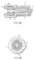
- FIG. 18A is a longitudinal cross sectional view along the XVIIIA-XVIIIA line of FIG. 16A , showing a third connection member and its periphery of the high-frequency snare of the endoscope system according to the third embodiment of the present invention;
- FIG. 18B is a longitudinal cross sectional view along the XVIIIB-XVIIIB line of FIG. 16B , showing the third connection member of the high-frequency snare of the endoscope system according to the third embodiment of the present invention
- FIG. 18C is a transverse cross sectional view showing the third connection member and its periphery of the high-frequency snare of the endoscope system according to the third embodiment of the present invention.
- FIG. 19 is a perspective view showing a state before a trap portion of the high-frequency snare is attached to the connecter of the endoscope in the endoscope system according to the third embodiment of the present invention.
- FIG. 20 is a longitudinal cross sectional view showing a state wherein the trap portion of the high-frequency snare is attached to the connecter of the endoscope in the endoscope system according to the third embodiment of the present invention
- FIG. 21 is a longitudinal cross sectional view showing a state before the third connection member of the high-frequency snare is attached to the second insertion connecter of the endoscope in the endoscope system according to the third embodiment of the present invention
- FIG. 22A is a longitudinal cross sectional view showing a state wherein the third connection member of the high-frequency snare is attached to the second insertion connecter of the endoscope in the endoscope system according to the third embodiment of the present invention
- FIG. 22B is another longitudinal cross sectional view showing a state wherein the third connection member of the high-frequency snare is attached to the second insertion connecter of the endoscope in the endoscope system according to the third embodiment of the present invention.
- FIG. 22C is a transverse cross sectional view showing a state wherein the third connection member of the high-frequency snare is attached to the second insertion connecter of the endoscope in the endoscope system according to the third embodiment of the present invention.
- FIGS. 1 and 2 show an endoscope 24 of an endoscope system according to the present embodiment.
- this endoscope 24 includes an elongated insertion portion 26 insertable into a body cavity.
- a proximal end of this insertion portion 26 is provided with an operating portion 28 to be held and operated by an operator.
- a connecting portion 30 is extended from this operating portion 28 , and an extended end of this connecting portion 30 is connected to a control unit 32 for controlling the endoscope 24 .
- the control unit 32 is provided with a light source for supplying illumination light to the endoscope 24 and the like.
- a channel 34 a for insertion of various accessories and suction is formed over the insertion portion 26 and the operating portion 28 .
- a distal end of this channel 34 a forms a distal opening 36 a at a distal end of the insertion portion 26
- a proximal end of the channel 34 a forms an insertion port 36 d as a proximal opening at an insertion connecter 38 a of the operating portion 28 .
- a suction duct 34 d for the suction is formed over the operating portion 28 and the connecting portion 30 .
- a distal end of this suction duct 34 d forms a suction opening 36 g in a suction connecter 38 d provided in the vicinity of the insertion connecter 38 a .
- a proximal end of the suction duct 34 d extends to the extended end of the connecting portion 30 , and is connected to a suction device such as a suction bottle.
- a plug member 40 formed of an elastic material such as a rubber is detachably attached to the insertion connecter 38 a and the suction connecter 38 d .
- One end of a communication path 42 formed at this plug member 40 is provided with a first engagement portion 44 a to be engaged with the insertion connecter 38 a airtightly to communicate the insertion port 36 d with the communication path 42 .
- the other end of the communication path 42 is provided with a second engagement portion 44 b to be engaged with the suction connecter 38 d airtightly to communicate the suction opening 36 g with the communication path 42 .
- a branch path is extended from the communication path 42 so as to lengthen the channel 34 a in a state wherein the plug member 40 is attached to the insertion connecter 38 a , and the branch path opens at an outer surface of the plug member 40 to form a channel opening 46 into which various accessories is insertable.
- the plug member 40 is provided with a lid member 48 to detachably cover the channel opening 46 to close the channel opening 46 airtightly.
- the channel 34 a communicates with the suction duct 34 d via the communication path 42 to allow the suction from the distal opening 36 a of the distal end of the insertion portion 26 , through the channel 34 a , the communication path 42 and the suction duct 34 d .
- various accessories is insertable into the insertion port 36 d from the channel opening 46 , through the channel 34 a and protruded from the distal opening 36 a . In this manner, through the attachment of the plug member 40 to the endoscope 24 , the endoscope 24 can be used alone.
- FIGS. 3 and 4 show a high-frequency snare 50 as the endoscopic accessory of the endoscope system according to the present embodiment.
- This high-frequency snare 50 includes a snare portion 52 for cutting a polyp or the like in a body cavity.
- This snare portion 52 includes a sheath 56 as an accessory insertion portion insertable into the body cavity.
- An operation wire 58 is inserted through this sheath 56 , and a proximal end of this operation wire 58 is connected to a slider 64 of a snare operating portion 60 provided at a proximal end of the sheath 56 .
- the operation wire 58 is movable forward and backward through forward and backward movement of the slider 64 with respect to a main body portion 62 of the snare operating portion 60 . It is to be noted that the proximal end of the operation wire 58 is connected to an electrode 66 in the slider 64 , and through connecting a high-frequency power source to this electrode 66 , a high-frequency current can be passed through the operation wire 58 .
- a distal end of the operation wire 58 is connected to a cutting wire 70 as a treatment portion via a connection chip 68 .
- the high-frequency current is to be passed through this cutting wire 70 via the operation wire 58 and the connection chip 68 .
- the cutting wire 70 is beforehand kinked so that the cutting wire 70 is elastically deformed to be crushed into an elongated shape when the operation wire 58 is moved backward and drawn into the sheath 56 and the cutting wire 70 is expanded and opened into a loop shape when the operation wire 58 is moved forward and protruded from the sheath 56 .
- a trap portion 72 as a capture portion is connected to the snare portion 52 of the high-frequency snare 50 , the trap portion 72 to be attached to the endoscope 24 , and separate and capture the polyp or the like being sucked from the channel 34 a to the suction duct 34 d , from blood, soil and the like.
- first connection member 74 a In the trap portion 72 , inner cavities of a first connection member 74 a , an insertion tube 76 , a side tube 78 , a case 80 and a second connection member 74 b form a communication path 82 to communicate the channel 34 a with the suction duct 34 d when the trap portion 72 is attached to the endoscope 24 . That is, the trap portion 72 is provided with the first connection member 74 a formed of an elastic material and to be connected to the insertion connecter 38 a of the endoscope 24 airtightly to communicate the insertion port 36 d with the communication path 82 .
- This first connection member 74 a is integrally connected to one end of the insertion tube 76 formed of an elastic material.
- This insertion tube 76 is connected to the case 80 via the side tube 78 extending in a radial direction of the insertion tube 76 .
- This case 80 is formed of a transparent material and the inside of the case can be observed.
- a trap 84 is detachably attached to the case 80 , and this trap 84 is provided with a mesh portion 86 as a capture unit to be interposed in the communication path 82 , and separate and capture the polyp or the like being sucked along the communication path 82 , from the blood, the soil and the like.
- the second connection member 74 b is connected to the case 80 , the second connection member 74 b formed of an elastic material and to be connected to the suction connecter 38 d of the endoscope 24 airtightly to communicate the communication path 82 with the suction opening 36 g.
- the sheath 56 of the snare portion 52 is connected to the trap portion 72 so that the sheath 56 is movable forward and backward in a longitudinal axial direction thereof. That is, the sheath 56 is extractably inserted through inner cavities of the insertion tube 76 and the first connection member 74 a and movable forward and backward in the longitudinal axial direction thereof. It is to be noted that at the end of the insertion tube 76 opposite to the first connection member 74 a , an end opening is closed through elastic deformation when the sheath 56 is extracted, to keep the communication path 82 airtight.
- the sheath 56 of the snare portion 52 is fixed to the trap portion 72 when the trap portion 72 is detached from the endoscope 24 and this fixing is released when the trap portion 72 is attached to the endoscope 24 . That is, an engagement groove 88 is formed at an outer peripheral surface of the sheath 56 of the snare portion 52 , and an engagement member 90 to engage with the engagement groove 88 of the sheath 56 so as to engage the sheath 56 with the first connection member 74 a is protruded from an inner peripheral surface of the first connection member 74 a of the trap portion 72 .
- the arrangement of the engagement groove 88 with respect to the longitudinal axial direction of the sheath 56 is set so that the distal end of the sheath 56 does not protrude from the endoscope 24 in a state wherein the sheath 56 is inserted into the channel 34 a of the endoscope 24 and the trap portion 72 is attached to the endoscope 24 .
- the trap portion 72 is attached to the endoscope 24 and the first connection member 74 a is connected to the insertion connecter 38 a
- the engagement member 90 is pushed away by the insertion connecter 38 a , and engagement between the engagement member 90 and the engagement groove 88 is released.
- the insertion connecter 38 a , the engagement groove 88 and the engagement member 90 form a switch mechanism to keep the high-frequency snare 50 in a fixed state wherein the sheath 56 is fixed to the trap portion 72 while the trap portion 72 is detached from the endoscope 24 and switch the high-frequency snare 50 to a released state wherein this fixing is released when the trap portion 72 is attached to the endoscope 24 .
- FIGS. 5 to 8 There will hereinafter be described a case wherein a polyp 92 is cut in a body cavity under observation with the endoscope and the cut polyp 92 is sucked and gathered.
- the insertion portion 26 of the endoscope 24 is inserted into the body cavity, and the distal end of the insertion portion 26 is guided so that the polyp 92 falls into a view field. Then, as shown in FIG. 5 , the plug member 40 is detached from the endoscope 24 , and the sheath 56 of the high-frequency snare 50 is inserted into the insertion port 36 d of the endoscope 24 and through the channel 34 a . Subsequently, as shown in FIG.
- the first connection member 74 a of the trap portion 72 of the high-frequency snare 50 is connected to the insertion connecter 38 a of the endoscope 24
- the second connection member 74 b is connected to the suction connecter 38 d , whereby the trap portion 72 is attached to the endoscope 24 .
- the engagement member 90 is pushed away by the insertion connecter 38 a to release the engagement between the engagement member 90 and the engagement groove 88 , so that the sheath 56 become movable forward and backward with respect to the trap portion 72 .
- the sheath 56 is pushed inward to protrude the distal end of the sheath 56 from the distal opening 36 a of the insertion portion 26 of the endoscope 24 .
- the slider 64 is moved forward with respect to the main body portion 62 of the snare operating portion 60 , the cutting wire 70 is protruded from the distal end of the sheath 56 and expanded and opened into the loop shape, and the polyp 92 is caught by the cutting wire 70 .
- the slider 64 is moved backward with respect to the main body portion 62 , the cutting wire 70 is drawn into the sheath 56 and contracted and closed to tighten the polyp 92 .
- the high-frequency power source is operated to pass the high-frequency current through the cutting wire 70 , thereby cutting the polyp 92 . Such an operation is repeated to cut a plurality of polyps 92 .
- the suction device is operated to suck the cut polyp 92 from the distal opening 36 a of the insertion portion 26 of the endoscope 24 .
- the sucked polyp 92 is sucked from the channel 34 a of the endoscope 24 into the insertion tube 76 , the side tube 78 and the case 80 of the trap portion 72 , and separated from the blood, the soil and the like and captured, by the mesh portion 86 of the trap 84 in the case 80 .
- the trap 84 is detached from the case 80 , and the polyp 92 captured by the mesh portion 86 is gathered and sent for pathological examination.
- the endoscope system of the present embodiment produces the following effect.
- the snare portion 52 for cutting the polyp 92 in the body cavity is integrally connected to the trap portion 72 attached to the endoscope 24 and to capture the polyp 92 being sucked from the channel 34 a into the suction duct 34 d . Therefore, loss of the trap portion 72 , which is comparatively small and easily lost, is prevented.
- both the snare portion 52 and the trap portion 72 is simultaneously prepared and do not have to be prepared separately or independently. Therefore, the preparation of the endoscope system is facilitated.
- the channel 34 a of the endoscope 24 is used. Therefore, a cross sectional area of the suction passage orthogonal to the longitudinal axial direction thereof can be comparatively enlarged, and a suction and gather efficiency is increased.
- the sheath 56 of the high-frequency snare 50 is movable forward and backward in the longitudinal axial direction thereof with respect to the trap portion 72 . Therefore, even when the trap portion 72 is attached to the endoscope 24 , the distal end of the sheath 56 is movable forward and backward in the body cavity through operating the sheath 56 to move forward and backward with respect to the trap portion 72 . Therefore, operability of the high-frequency snare 50 is improved.
- the sheath 56 is configured to be fixed to the trap portion 72 through engaging the engagement member 90 of the first connection member 74 a of the trap portion 72 with the engagement groove 88 of the sheath 56 of the snare portion 52 . Therefore, when the snare portion 52 is not used, the sheath 56 is fixed to the trap portion 72 so that an unnecessary movement of the sheath 56 is prevented. Especially, the sheath 56 is fixed to the trap portion 72 before attaching the trap portion 72 to the endoscope 24 , whereby the sheath 56 is prevented from being improperly moved while the trap portion 72 is being attached to the endoscope 24 .
- the engagement member 90 is pushed away by the insertion connecter 38 a of the endoscope 24 to release the engagement between the engagement member 90 and the engagement groove 88 , and the sheath 56 become automatically movable forward and backward with respect to the trap portion 72 .
- an operation for releasing the engagement between the engagement member 90 and the engagement groove 88 is not separately required, and operability of the high-frequency snare 50 is improved.
- FIGS. 9A to 14 show a second embodiment of the present invention.
- a configuration having a function similar to that of the first embodiment is denoted with the same reference numerals, and description thereof is omitted.
- the distal end of the sheath is inserted directly into the insertion port of the endoscope.
- FIGS. 9A and 9B show the insertion connecter 38 a and the suction connecter 38 d of the endoscope 24 of the endoscope system according to the present embodiment.
- a protruding end surface of the insertion connecter 38 a of the endoscope 24 is provided with a pair of claw portions 94 protruded so as to face each other, and press protrusions 96 to cooperate with holding members 102 (see FIG. 11 ), described later, are formed on inner sides of the pair of claw portions 94 , respectively.
- FIGS. 10 and 11 show the high-frequency snare 50 of the endoscope system according to the present embodiment.
- a tubular member 98 fits into the distal end of the sheath 56 of the snare portion 52 of the high-frequency snare 50 , and a protruding portion 100 is formed over the whole periphery of an outer peripheral surface of the distal end of the sheath 56 .
- an inner peripheral surface of the first connection member 74 a of the trap portion 72 is provided with a pair of holding members 102 so as to face each other, and the distal end of the sheath 56 is releasably held by the pair of holding members 102 .
- each holding member 102 a pair of arm portions 106 a , 106 b are extended from a hinge portion 104 , and distal ends of the pair of arm portions 106 a , 106 b are provided with engagement protrusions 108 a , 108 b , respectively.
- the holding member 102 is formed of an elastic material, the pair of arm portions 106 a , 106 b are urged about the hinge portion 104 in a closing direction, and the engagement protrusions 108 a , 108 b of the pair of arm portions 106 a , 106 b are engaged with a distal end side and a rear end side of the protruding portion 100 at the distal end of the sheath 56 , respectively.
- the distal end of the sheath 56 is held by the pair of holding members 102 .
- window portions 110 are formed through the first connection member 74 a on rear surface sides of the hinge portions 104 of the holding members 102 . Then, when the trap portion 72 is attached to the endoscope 24 and the insertion connecter 38 a of the endoscope 24 is connected to the first connection member 74 a , the claw portions 94 of the insertion connecter 38 a are arranged on an outer peripheral surface side of the first connection member 74 a , and the press protrusions 96 of the claw portions 94 press back surfaces of the hinge portions 104 of the holding members 102 via the window portions 110 .
- the pressed holding members 102 are elastically deformed to open the pair of arm portions 106 a , 106 b about the hinge portion 104 , engagement between the engagement protrusions 108 a , 108 b and the protruding portion 100 of the sheath 56 is released, and the sheath 56 become movable forward and backward with respect to the first connection member 74 a.
- the claw portions 94 , the window portions 110 and the holding members 102 form the switch mechanism.
- first connection member 74 a is formed of a rigid material, and a connection end surface of the first connection member 74 a is covered with a packing 103 for communicating the insertion port 36 d of the endoscope 24 with the communication path 82 of the trap portion 72 airtightly.
- the trap portion 72 is previously arranged at the distal end of the snare portion 52 , the plug member 40 is detached from the endoscope 24 , and the trap portion 72 is attached to the endoscope 24 .
- the first connection member 74 a is connected to the insertion connecter 38 a
- the distal end of the sheath 56 of the high-frequency snare 50 is held by the holding member 102 , and the sheath 56 is fixed to the trap portion 72 .
- the distal end surface of the sheath 56 is arranged so as to face the insertion port 36 d of the endoscope 24 and, through pushing the sheath 56 inwards, the sheath 56 is inserted into the insertion port 36 d directly and through a channel 34 a.
- the endoscope system of the present embodiment has the following effect.
- the distal end surface of the sheath 56 of the high-frequency snare 50 is arranged so as to face the insertion port 36 d of the endoscope 24 . Therefore, when the sheath 56 is moved forward with respect to the trap portion 72 , the sheath 56 is inserted directly into the insertion port 36 d and through the channel 34 a . In this manner, an inserting operation of the sheath 56 into the channel 34 a is facilitated.
- FIGS. 15 to 22B show a third embodiment of the present invention.
- a configuration having a function similar to that of the second embodiment is denoted with the same reference numerals, and description thereof is omitted.
- a channel for insertion of the sheath of the high-frequency snare is formed separately from a channel for the suction of a polyp or the like.
- FIG. 15 shows the endoscope 24 of the endoscope system according to the present embodiment.
- the endoscope 24 of the present embodiment is provided with a first channel 34 b having a configuration similar to that of the channel 34 a (see FIGS. 9A and 9B ) of the second embodiment. Furthermore, the endoscope 24 is provided with a second channel 34 c for insertion of the sheath 56 (see FIGS. 16A and 16 b ) of the high-frequency snare 50 separately from the first channel 34 b .
- a distal end of the second channel 34 c forms a second distal opening 36 c
- a proximal end of the second channel 34 c forms a second insertion port 36 f as a proximal opening in a second insertion connecter 38 c of the operating portion 28 .
- the first insertion port 36 e of the first channel 34 b , the suction opening 36 g and the second insertion port 36 f are arranged so as to form a vertex of a triangle.
- the plug member 40 is detachably attached to a first insertion connecter 38 b of the first channel 34 b , the suction connecter 38 d and the second insertion connecter 38 c .
- This plug member 40 is provided with a first communication path 42 a to communicate the first insertion port 36 e with suction opening 36 g and having a configuration similar to that of the communication path 42 (see FIGS. 9A and 9B ) of the second embodiment.
- the plug member 40 is provided with a second communication path 42 b extending so as to lengthen the second channel 34 c in a state wherein the plug member 40 is attached to the second insertion connecter 38 c .
- This second communication path 42 b includes a second channel opening 46 b and a second lid member 48 b having configurations similar to those of a first channel opening 46 a of the first communication path 42 a and a first lid member 48 a.
- a protruding end surface of the second insertion connecter 38 c is provided with a pair of protruding claw portions 94 including press protrusions 96 to cooperate with a holding member 102 (see FIGS. 18A and 18B ) described later, respectively.
- FIGS. 16A to 18C show the high-frequency snare 50 of the endoscope system according to the present embodiment.
- inner cavities of the first connection member 74 a , an L-shaped tube 105 , the case 80 and the second connection member 74 b form the communication path 82 .
- the first connection member 74 a is formed of an elastic material, and connected to the first insertion connecter 38 b of the endoscope 24 airtightly to communicate the first insertion port 36 e with the communication path 82 .
- the first connection member 74 a is connected to the case 80 via the L-shaped tube 105
- the case 80 is connected to the second connection member 74 b.
- a third connection member 74 c to be connected to the second insertion connecter 38 c is connected to one end of the insertion tube 76 , and the sheath 56 of the snare portion 52 is extractably inserted into the insertion tube 76 and the third connection member 74 c.
- the third connection member 74 c connected to one end of the insertion tube 76 has a substantially cylindrical shape, and the substantially cylindrical holding member 102 is disposed coaxially in this third connection member 74 c . It is to be noted that a clearance is formed between an inner peripheral surface of the third connection member 74 c and an outer peripheral surface of the holding member 102 so as to allow elastic deformation of the holding member 102 described later.
- an outer periphery of a cross section of a distal end of the sheath 56 of the snare portion 52 of the high-frequency snare 50 , orthogonal to a longitudinal axial direction thereof, has a substantially elliptic shape, and the distal end of the sheath 56 is provided with a pair of protruding portions 100 protruding in mutually opposite directions in one axial direction orthogonal to the longitudinal axis thereof. Then, the distal end of the sheath 56 is inserted into the holding member 102 , and an inside diameter of the holding member 102 is larger than a minor axis of the elliptic shape of the distal end of the sheath 56 , and shorter than a major axis. Therefore, the protruding portions 100 of the sheath 56 press an inner peripheral surface of the holding member 102 to elastically deform the holding member 102 , and engage with the inner peripheral surface of the holding member 102 .
- the pair of window portions 110 is formed through the third connection member 74 c so as to face each other with a central axis of the third connection member 74 c between them. Then, in the same manner as in the second embodiment, when the trap portion 72 is attached to the endoscope 24 , the press protrusions 96 of the claw portions 94 of the second insertion connecter 38 c press the outer peripheral surface of the holding member 102 via the window portions 110 .
- the pressed holding member 102 is compressed and deformed in a pressed direction, and outer and inner peripheries of a cross section orthogonal to a central axial direction thereof become a substantially elliptic shape wherein the pressed direction is a minor axial direction.
- the distal end of the sheath 56 is arranged so that the minor axial direction of the elliptic shape of the outer periphery of the cross section substantially matches with the pressed direction.
- the major and minor axes of the elliptic shape of the inner periphery of the cross section of the deformed holding member 102 become longer than those of the elliptic shape of the outer periphery of the cross section of the sheath 56 , respectively (see FIG. 22C ), and the engagement between the holding member 102 and the protruding portions 100 of the sheath 56 is released, so that the sheath 56 become movable forward and backward with respect to the third connection member 74 c.
- the plug member 40 is detached from the endoscope 24 , and the trap portion 72 of the high-frequency snare 50 is attached to the endoscope 24 .
- the first connection member 74 a is connected to the first insertion connecter 38 b
- the second connection member 74 b is connected to the suction connecter 38 d
- the third connection member 74 c is connected to the second insertion connecter 38 c.
- the first channel 34 b is connected to the suction duct 34 d via the communication path 82 of the trap portion 72 .
- the protruding portions 100 of the sheath 56 of the high-frequency snare 50 press the inner peripheral surface of the holding member 102 to elastically deform the holding member 102 , and engage with the holding member 102 , whereby the sheath 56 is fixed to the trap portion 72 .
- the third connection member 74 c is connected to the second insertion connecter 38 c , as shown in FIGS.
- the press protrusions 96 of the claw portions 94 of the second insertion connecter 38 c press the outer peripheral surface of the holding member 102 via the window portions 110 of the second connection member 74 b .
- the pressed holding member 102 is elastically deformed into the elliptic cross sectional shape, the major and minor axes of the elliptic shape of the inner periphery of the cross section are larger than those of the elliptic shape of the outer periphery of the cross section of the sheath 56 , respectively, the engagement between the holding member 102 and the protruding portions 100 of the sheath 56 is released, and the sheath 56 become movable forward and backward with respect to the trap portion 72 .
- the sheath 56 is pushed inwards, the sheath 56 is inserted through the second channel 34 c from the second insertion port 36 f , and the distal end of the sheath is protruded from the second distal opening 36 c at the distal end of the endoscope 24 to perform a cutting operation of a polyp 92 .
- the sheath 56 is not extracted from the second channel 34 c , and the polyp 92 is sucked from a first distal opening 36 b into the first channel 34 b and then the communication path 82 , and captured by the mesh portion 86 .
- the cutting, and the sucking and gathering of the polyp 92 are successively repeated.
- the endoscope system of the present embodiment produces the following effect.
- the second channel 34 c for the insertion of the sheath 56 of the high-frequency snare 50 is formed separately from and independently of the first channel 34 b for the sucking and gathering of the cut polyp 92 . Therefore, when the polyp 92 is sucked and gathered, the snare does not have to be extracted from the endoscope 24 , and the cutting, and the sucking and gathering of the polyp 92 can easily be repeated.
- the endoscope system to cut, and suck and gather the polyp 92 has been described as an example, but the present invention is applicable to any endoscope system to separate a part of a living tissue therefrom in a body cavity under observation with the endoscope and suck and gather the separated tissue.
Abstract
Description
Claims (8)
Applications Claiming Priority (3)
| Application Number | Priority Date | Filing Date | Title |
|---|---|---|---|
| JP2005-242938 | 2005-08-24 | ||
| JP2005242938A JP4716821B2 (en) | 2005-08-24 | 2005-08-24 | Endoscope system, endoscope treatment tool, and endoscope |
| PCT/JP2006/316332 WO2007023769A1 (en) | 2005-08-24 | 2006-08-21 | Endoscope system |
Related Parent Applications (1)
| Application Number | Title | Priority Date | Filing Date |
|---|---|---|---|
| PCT/JP2006/316332 Continuation WO2007023769A1 (en) | 2005-08-24 | 2006-08-21 | Endoscope system |
Publications (2)
| Publication Number | Publication Date |
|---|---|
| US20080208004A1 US20080208004A1 (en) | 2008-08-28 |
| US7775973B2 true US7775973B2 (en) | 2010-08-17 |
Family
ID=37771514
Family Applications (1)
| Application Number | Title | Priority Date | Filing Date |
|---|---|---|---|
| US12/035,762 Active 2027-08-13 US7775973B2 (en) | 2005-08-24 | 2008-02-22 | Endoscope system |
Country Status (4)
| Country | Link |
|---|---|
| US (1) | US7775973B2 (en) |
| EP (1) | EP1917903B1 (en) |
| JP (1) | JP4716821B2 (en) |
| WO (1) | WO2007023769A1 (en) |
Cited By (41)
| Publication number | Priority date | Publication date | Assignee | Title |
|---|---|---|---|---|
| US20090287111A1 (en) * | 2008-05-16 | 2009-11-19 | Us Endoscopy Group, Inc. | Endoscope collection vessel |
| US8287556B2 (en) | 2008-06-17 | 2012-10-16 | Apollo Endosurgery, Inc. | Endoscopic suturing system |
| US8348929B2 (en) | 2009-08-05 | 2013-01-08 | Rocin Laboratories, Inc. | Endoscopically-guided tissue aspiration system for safely removing fat tissue from a patient |
| US8465471B2 (en) | 2009-08-05 | 2013-06-18 | Rocin Laboratories, Inc. | Endoscopically-guided electro-cauterizing power-assisted fat aspiration system for aspirating visceral fat tissue within the abdomen of a patient |
| US8540735B2 (en) | 2010-12-16 | 2013-09-24 | Apollo Endosurgery, Inc. | Endoscopic suture cinch system |
| US8679136B2 (en) | 2008-06-17 | 2014-03-25 | Apollo Endosurgery, Inc. | Needle capture device |
| US8926502B2 (en) | 2011-03-07 | 2015-01-06 | Endochoice, Inc. | Multi camera endoscope having a side service channel |
| US9101287B2 (en) | 2011-03-07 | 2015-08-11 | Endochoice Innovation Center Ltd. | Multi camera endoscope assembly having multiple working channels |
| US9101268B2 (en) | 2009-06-18 | 2015-08-11 | Endochoice Innovation Center Ltd. | Multi-camera endoscope |
| US9101266B2 (en) | 2011-02-07 | 2015-08-11 | Endochoice Innovation Center Ltd. | Multi-element cover for a multi-camera endoscope |
| US9314147B2 (en) | 2011-12-13 | 2016-04-19 | Endochoice Innovation Center Ltd. | Rotatable connector for an endoscope |
| US9320419B2 (en) | 2010-12-09 | 2016-04-26 | Endochoice Innovation Center Ltd. | Fluid channeling component of a multi-camera endoscope |
| US9402533B2 (en) | 2011-03-07 | 2016-08-02 | Endochoice Innovation Center Ltd. | Endoscope circuit board assembly |
| US9486126B2 (en) | 2008-06-17 | 2016-11-08 | Apollo Endosurgery, Inc. | Endoscopic helix tissue grasping device |
| US9492063B2 (en) | 2009-06-18 | 2016-11-15 | Endochoice Innovation Center Ltd. | Multi-viewing element endoscope |
| US9554692B2 (en) | 2009-06-18 | 2017-01-31 | EndoChoice Innovation Ctr. Ltd. | Multi-camera endoscope |
| US9560954B2 (en) | 2012-07-24 | 2017-02-07 | Endochoice, Inc. | Connector for use with endoscope |
| US9560953B2 (en) | 2010-09-20 | 2017-02-07 | Endochoice, Inc. | Operational interface in a multi-viewing element endoscope |
| US9642513B2 (en) | 2009-06-18 | 2017-05-09 | Endochoice Inc. | Compact multi-viewing element endoscope system |
| US9655502B2 (en) | 2011-12-13 | 2017-05-23 | EndoChoice Innovation Center, Ltd. | Removable tip endoscope |
| US9706903B2 (en) | 2009-06-18 | 2017-07-18 | Endochoice, Inc. | Multiple viewing elements endoscope system with modular imaging units |
| US9713417B2 (en) | 2009-06-18 | 2017-07-25 | Endochoice, Inc. | Image capture assembly for use in a multi-viewing elements endoscope |
| US9788831B2 (en) | 2013-03-12 | 2017-10-17 | Apollo Endosurgery Us, Inc. | Endoscopic suture cinch system with replaceable cinch |
| US9814374B2 (en) | 2010-12-09 | 2017-11-14 | Endochoice Innovation Center Ltd. | Flexible electronic circuit board for a multi-camera endoscope |
| US9872609B2 (en) | 2009-06-18 | 2018-01-23 | Endochoice Innovation Center Ltd. | Multi-camera endoscope |
| US9901244B2 (en) | 2009-06-18 | 2018-02-27 | Endochoice, Inc. | Circuit board assembly of a multiple viewing elements endoscope |
| US9986899B2 (en) | 2013-03-28 | 2018-06-05 | Endochoice, Inc. | Manifold for a multiple viewing elements endoscope |
| US9993142B2 (en) | 2013-03-28 | 2018-06-12 | Endochoice, Inc. | Fluid distribution device for a multiple viewing elements endoscope |
| US10080486B2 (en) | 2010-09-20 | 2018-09-25 | Endochoice Innovation Center Ltd. | Multi-camera endoscope having fluid channels |
| US10165929B2 (en) | 2009-06-18 | 2019-01-01 | Endochoice, Inc. | Compact multi-viewing element endoscope system |
| US10203493B2 (en) | 2010-10-28 | 2019-02-12 | Endochoice Innovation Center Ltd. | Optical systems for multi-sensor endoscopes |
| US10448946B2 (en) | 2013-03-12 | 2019-10-22 | Apollo Endosurgery Us, Inc. | Endoscopic suture cinch |
| US10499794B2 (en) | 2013-05-09 | 2019-12-10 | Endochoice, Inc. | Operational interface in a multi-viewing element endoscope |
| US20210162101A1 (en) * | 2018-05-18 | 2021-06-03 | Stryker Corporation | Manifolds For A Medical Waste Collection Assembly And Methods Of Collecting A Tissue Sample With The Same |
| US11051800B2 (en) | 2016-08-10 | 2021-07-06 | Apollo Endosurgery Us, Inc. | Endoscopic suturing system having external instrument channel |
| US11141147B2 (en) | 2016-08-10 | 2021-10-12 | Apollo Endosurgery Us, Inc. | Endoscopic suturing system having external instrument channel |
| US11278190B2 (en) | 2009-06-18 | 2022-03-22 | Endochoice, Inc. | Multi-viewing element endoscope |
| US11547275B2 (en) | 2009-06-18 | 2023-01-10 | Endochoice, Inc. | Compact multi-viewing element endoscope system |
| US11812951B2 (en) | 2008-06-17 | 2023-11-14 | Apollo Endosurgery Us, Inc. | Endoscopic needle assembly |
| US11864734B2 (en) | 2009-06-18 | 2024-01-09 | Endochoice, Inc. | Multi-camera endoscope |
| US11889986B2 (en) | 2010-12-09 | 2024-02-06 | Endochoice, Inc. | Flexible electronic circuit board for a multi-camera endoscope |
Families Citing this family (4)
| Publication number | Priority date | Publication date | Assignee | Title |
|---|---|---|---|---|
| JP4814274B2 (en) * | 2008-03-12 | 2011-11-16 | 昌貴 鮒田 | Medical instruments |
| JP6312465B2 (en) * | 2014-03-04 | 2018-04-18 | 株式会社八光 | Tissue excision instrument for loop endoscope |
| US10582949B2 (en) * | 2014-09-30 | 2020-03-10 | Kaushikkumar Vallabhadas SHAH | Sheath assembly and multihole catheter for different fields of endoscopic surgery involving suction, irrigation and material removal |
| WO2021137106A1 (en) * | 2019-12-30 | 2021-07-08 | Auris Health, Inc. | Specimen collector for robotic medical system |
Citations (20)
| Publication number | Priority date | Publication date | Assignee | Title |
|---|---|---|---|---|
| US4083706A (en) * | 1974-10-25 | 1978-04-11 | Wiley Corless W | Sterile trap accessory for use with surgical aspirator |
| JPS6274804A (en) | 1985-09-27 | 1987-04-06 | 東京都 | Vertical conveyor type duster |
| US4794913A (en) * | 1986-12-04 | 1989-01-03 | Olympus Optical Co., Ltd. | Suction control unit for an endoscope |
| JPH01160525A (en) | 1987-12-17 | 1989-06-23 | Olympus Optical Co Ltd | Endoscope |
| US4968309A (en) * | 1986-08-06 | 1990-11-06 | Ingvar Andersson | Connection preferably for medical use |
| JPH0614991A (en) | 1992-07-02 | 1994-01-25 | Olympus Optical Co Ltd | Recovering tool of in vivo washing liquid |
| JPH0759729A (en) | 1993-08-26 | 1995-03-07 | Fuji Photo Optical Co Ltd | Endoscope with relay part for washing |
| US5749829A (en) * | 1995-05-16 | 1998-05-12 | Olympus Optical Co., Ltd. | Endoscope system |
| JPH11226024A (en) | 1998-02-17 | 1999-08-24 | Olympus Optical Co Ltd | Treating implement for endoscope |
| JPH11267089A (en) | 1998-03-24 | 1999-10-05 | Olympus Optical Co Ltd | Polyp recovering endoscope system |
| US5971917A (en) * | 1997-02-26 | 1999-10-26 | Fuji Photo Optical Co., Ltd. | Endoscope having washing ports |
| US6110127A (en) * | 1998-02-17 | 2000-08-29 | Olympus Optical, Co., Ltd. | Medical instrument for use in combination with an endoscope |
| JP2000237126A (en) | 1999-02-19 | 2000-09-05 | Fuji Photo Optical Co Ltd | Passage structure for endoscope |
| US6142956A (en) * | 1996-11-25 | 2000-11-07 | Symbiosis Corporation | Proximal actuation handle for a biopsy forceps instrument having irrigation and aspiration capabilities |
| US6632182B1 (en) * | 1998-10-23 | 2003-10-14 | The Trustees Of Columbia University In The City Of New York | Multiple bit, multiple specimen endoscopic biopsy forceps |
| WO2004075740A1 (en) | 2003-02-25 | 2004-09-10 | Zeon Corporation | Cut tissue piece recovery device |
| US20040220452A1 (en) * | 2001-06-11 | 2004-11-04 | Michael Shalman | Endoscope with cleaning optics |
| US20050027165A1 (en) * | 2003-04-07 | 2005-02-03 | Jean Rovegno | Removable operating device for a flexible endoscopic probe for medical purposes |
| US20050119522A1 (en) * | 2003-11-28 | 2005-06-02 | Olympus Corporation | Endoscope treatment tool insertion-extraction system |
| JP2005211453A (en) | 2004-01-30 | 2005-08-11 | Olympus Corp | Endoscope |
-
2005
- 2005-08-24 JP JP2005242938A patent/JP4716821B2/en active Active
-
2006
- 2006-08-21 WO PCT/JP2006/316332 patent/WO2007023769A1/en active Application Filing
- 2006-08-21 EP EP06796595A patent/EP1917903B1/en not_active Expired - Fee Related
-
2008
- 2008-02-22 US US12/035,762 patent/US7775973B2/en active Active
Patent Citations (23)
| Publication number | Priority date | Publication date | Assignee | Title |
|---|---|---|---|---|
| US4083706A (en) * | 1974-10-25 | 1978-04-11 | Wiley Corless W | Sterile trap accessory for use with surgical aspirator |
| JPS6274804A (en) | 1985-09-27 | 1987-04-06 | 東京都 | Vertical conveyor type duster |
| US4968309A (en) * | 1986-08-06 | 1990-11-06 | Ingvar Andersson | Connection preferably for medical use |
| US4794913A (en) * | 1986-12-04 | 1989-01-03 | Olympus Optical Co., Ltd. | Suction control unit for an endoscope |
| JPH01160525A (en) | 1987-12-17 | 1989-06-23 | Olympus Optical Co Ltd | Endoscope |
| JPH0614991A (en) | 1992-07-02 | 1994-01-25 | Olympus Optical Co Ltd | Recovering tool of in vivo washing liquid |
| JPH0759729A (en) | 1993-08-26 | 1995-03-07 | Fuji Photo Optical Co Ltd | Endoscope with relay part for washing |
| US5749829A (en) * | 1995-05-16 | 1998-05-12 | Olympus Optical Co., Ltd. | Endoscope system |
| US6142956A (en) * | 1996-11-25 | 2000-11-07 | Symbiosis Corporation | Proximal actuation handle for a biopsy forceps instrument having irrigation and aspiration capabilities |
| US5971917A (en) * | 1997-02-26 | 1999-10-26 | Fuji Photo Optical Co., Ltd. | Endoscope having washing ports |
| JPH11226024A (en) | 1998-02-17 | 1999-08-24 | Olympus Optical Co Ltd | Treating implement for endoscope |
| US6068603A (en) * | 1998-02-17 | 2000-05-30 | Olympus Optical Co., Ltd. | Medical instrument for use in combination with an endoscope |
| US6110127A (en) * | 1998-02-17 | 2000-08-29 | Olympus Optical, Co., Ltd. | Medical instrument for use in combination with an endoscope |
| DE19906592A1 (en) | 1998-02-17 | 1999-09-02 | Olympus Optical Co | Medical instrument for combined use with endoscope having cutting wire loop for removing tissue sample |
| JPH11267089A (en) | 1998-03-24 | 1999-10-05 | Olympus Optical Co Ltd | Polyp recovering endoscope system |
| US6632182B1 (en) * | 1998-10-23 | 2003-10-14 | The Trustees Of Columbia University In The City Of New York | Multiple bit, multiple specimen endoscopic biopsy forceps |
| JP2000237126A (en) | 1999-02-19 | 2000-09-05 | Fuji Photo Optical Co Ltd | Passage structure for endoscope |
| US20040220452A1 (en) * | 2001-06-11 | 2004-11-04 | Michael Shalman | Endoscope with cleaning optics |
| WO2004075740A1 (en) | 2003-02-25 | 2004-09-10 | Zeon Corporation | Cut tissue piece recovery device |
| US20050027165A1 (en) * | 2003-04-07 | 2005-02-03 | Jean Rovegno | Removable operating device for a flexible endoscopic probe for medical purposes |
| US20050119522A1 (en) * | 2003-11-28 | 2005-06-02 | Olympus Corporation | Endoscope treatment tool insertion-extraction system |
| JP2005152502A (en) | 2003-11-28 | 2005-06-16 | Olympus Corp | Inserting/removing system of instrument for endoscope |
| JP2005211453A (en) | 2004-01-30 | 2005-08-11 | Olympus Corp | Endoscope |
Non-Patent Citations (4)
| Title |
|---|
| International Search Report dated Nov. 7, 2006 issued in corresponding PCT Application No. PCT/JP2006/316332. |
| Letter from German associate dated Jun. 5, 2009 forwarding the Search Report dated May 8, 2009 to Japanese associate, including discussion of relevancy thereof. |
| Search Report issued by European Patent Office in connection with corresponding application No. EP 06 79 6595 on May 8, 2009. |
| Written Opinion dated Nov. 7, 2006 issued in corresponding PCT Application No. PCT/JP2006/316332. |
Cited By (78)
| Publication number | Priority date | Publication date | Assignee | Title |
|---|---|---|---|---|
| US20090287111A1 (en) * | 2008-05-16 | 2009-11-19 | Us Endoscopy Group, Inc. | Endoscope collection vessel |
| US11812951B2 (en) | 2008-06-17 | 2023-11-14 | Apollo Endosurgery Us, Inc. | Endoscopic needle assembly |
| US8287556B2 (en) | 2008-06-17 | 2012-10-16 | Apollo Endosurgery, Inc. | Endoscopic suturing system |
| US10799232B2 (en) | 2008-06-17 | 2020-10-13 | Apollo Endosurgery Us, Inc. | Method of endoscopic suturing |
| US11083364B2 (en) | 2008-06-17 | 2021-08-10 | Apollo Endosurgery Us, Inc. | Endoscopic tissue grasping systems and methods |
| US8679136B2 (en) | 2008-06-17 | 2014-03-25 | Apollo Endosurgery, Inc. | Needle capture device |
| US9867610B2 (en) | 2008-06-17 | 2018-01-16 | Apollo Endosurgery Us, Inc. | Endoscopic suturing system with retained end cap |
| US11534160B2 (en) | 2008-06-17 | 2022-12-27 | Apollo Endosurgery, Inc. | Endoscopic needle assembly |
| US9486126B2 (en) | 2008-06-17 | 2016-11-08 | Apollo Endosurgery, Inc. | Endoscopic helix tissue grasping device |
| US9198562B2 (en) | 2008-06-17 | 2015-12-01 | Apollo Endosurgery, Inc. | Endoscopic needle assembly |
| US9706903B2 (en) | 2009-06-18 | 2017-07-18 | Endochoice, Inc. | Multiple viewing elements endoscope system with modular imaging units |
| US10165929B2 (en) | 2009-06-18 | 2019-01-01 | Endochoice, Inc. | Compact multi-viewing element endoscope system |
| US11547275B2 (en) | 2009-06-18 | 2023-01-10 | Endochoice, Inc. | Compact multi-viewing element endoscope system |
| US10791910B2 (en) | 2009-06-18 | 2020-10-06 | Endochoice, Inc. | Multiple viewing elements endoscope system with modular imaging units |
| US10765305B2 (en) | 2009-06-18 | 2020-09-08 | Endochoice, Inc. | Circuit board assembly of a multiple viewing elements endoscope |
| US11534056B2 (en) | 2009-06-18 | 2022-12-27 | Endochoice, Inc. | Multi-camera endoscope |
| US11864734B2 (en) | 2009-06-18 | 2024-01-09 | Endochoice, Inc. | Multi-camera endoscope |
| US9492063B2 (en) | 2009-06-18 | 2016-11-15 | Endochoice Innovation Center Ltd. | Multi-viewing element endoscope |
| US9554692B2 (en) | 2009-06-18 | 2017-01-31 | EndoChoice Innovation Ctr. Ltd. | Multi-camera endoscope |
| US10638922B2 (en) | 2009-06-18 | 2020-05-05 | Endochoice, Inc. | Multi-camera endoscope |
| US10799095B2 (en) | 2009-06-18 | 2020-10-13 | Endochoice, Inc. | Multi-viewing element endoscope |
| US9642513B2 (en) | 2009-06-18 | 2017-05-09 | Endochoice Inc. | Compact multi-viewing element endoscope system |
| US10905320B2 (en) | 2009-06-18 | 2021-02-02 | Endochoice, Inc. | Multi-camera endoscope |
| US9706905B2 (en) | 2009-06-18 | 2017-07-18 | Endochoice Innovation Center Ltd. | Multi-camera endoscope |
| US10791909B2 (en) | 2009-06-18 | 2020-10-06 | Endochoice, Inc. | Image capture assembly for use in a multi-viewing elements endoscope |
| US11471028B2 (en) | 2009-06-18 | 2022-10-18 | Endochoice, Inc. | Circuit board assembly of a multiple viewing elements endoscope |
| US9713417B2 (en) | 2009-06-18 | 2017-07-25 | Endochoice, Inc. | Image capture assembly for use in a multi-viewing elements endoscope |
| US11278190B2 (en) | 2009-06-18 | 2022-03-22 | Endochoice, Inc. | Multi-viewing element endoscope |
| US9101268B2 (en) | 2009-06-18 | 2015-08-11 | Endochoice Innovation Center Ltd. | Multi-camera endoscope |
| US10092167B2 (en) | 2009-06-18 | 2018-10-09 | Endochoice, Inc. | Multiple viewing elements endoscope system with modular imaging units |
| US10912445B2 (en) | 2009-06-18 | 2021-02-09 | Endochoice, Inc. | Compact multi-viewing element endoscope system |
| US9901244B2 (en) | 2009-06-18 | 2018-02-27 | Endochoice, Inc. | Circuit board assembly of a multiple viewing elements endoscope |
| US9872609B2 (en) | 2009-06-18 | 2018-01-23 | Endochoice Innovation Center Ltd. | Multi-camera endoscope |
| US9925314B2 (en) | 2009-08-05 | 2018-03-27 | Rocin Laboratories, Inc. | Method of performing intra-abdominal tissue aspiration to ameliorate the metabolic syndrome, or abdominal obesity |
| US11259862B2 (en) | 2009-08-05 | 2022-03-01 | Rocin Laboratories, Inc. | Coaxial-driven tissue aspiration instrument system |
| US8465471B2 (en) | 2009-08-05 | 2013-06-18 | Rocin Laboratories, Inc. | Endoscopically-guided electro-cauterizing power-assisted fat aspiration system for aspirating visceral fat tissue within the abdomen of a patient |
| US9833279B2 (en) | 2009-08-05 | 2017-12-05 | Rocin Laboratories, Inc. | Twin-cannula tissue aspiration instrument system |
| US8348929B2 (en) | 2009-08-05 | 2013-01-08 | Rocin Laboratories, Inc. | Endoscopically-guided tissue aspiration system for safely removing fat tissue from a patient |
| US9986892B2 (en) | 2010-09-20 | 2018-06-05 | Endochoice, Inc. | Operational interface in a multi-viewing element endoscope |
| US10080486B2 (en) | 2010-09-20 | 2018-09-25 | Endochoice Innovation Center Ltd. | Multi-camera endoscope having fluid channels |
| US9560953B2 (en) | 2010-09-20 | 2017-02-07 | Endochoice, Inc. | Operational interface in a multi-viewing element endoscope |
| US10203493B2 (en) | 2010-10-28 | 2019-02-12 | Endochoice Innovation Center Ltd. | Optical systems for multi-sensor endoscopes |
| US11543646B2 (en) | 2010-10-28 | 2023-01-03 | Endochoice, Inc. | Optical systems for multi-sensor endoscopes |
| US9814374B2 (en) | 2010-12-09 | 2017-11-14 | Endochoice Innovation Center Ltd. | Flexible electronic circuit board for a multi-camera endoscope |
| US11497388B2 (en) | 2010-12-09 | 2022-11-15 | Endochoice, Inc. | Flexible electronic circuit board for a multi-camera endoscope |
| US10898063B2 (en) | 2010-12-09 | 2021-01-26 | Endochoice, Inc. | Flexible electronic circuit board for a multi camera endoscope |
| US10182707B2 (en) | 2010-12-09 | 2019-01-22 | Endochoice Innovation Center Ltd. | Fluid channeling component of a multi-camera endoscope |
| US11889986B2 (en) | 2010-12-09 | 2024-02-06 | Endochoice, Inc. | Flexible electronic circuit board for a multi-camera endoscope |
| US9320419B2 (en) | 2010-12-09 | 2016-04-26 | Endochoice Innovation Center Ltd. | Fluid channeling component of a multi-camera endoscope |
| US9089325B2 (en) | 2010-12-16 | 2015-07-28 | Apollo Endosurgery, Inc. | Methods of applying a suture cinch |
| US8540735B2 (en) | 2010-12-16 | 2013-09-24 | Apollo Endosurgery, Inc. | Endoscopic suture cinch system |
| US10070774B2 (en) | 2011-02-07 | 2018-09-11 | Endochoice Innovation Center Ltd. | Multi-element cover for a multi-camera endoscope |
| US9351629B2 (en) | 2011-02-07 | 2016-05-31 | Endochoice Innovation Center Ltd. | Multi-element cover for a multi-camera endoscope |
| US9101266B2 (en) | 2011-02-07 | 2015-08-11 | Endochoice Innovation Center Ltd. | Multi-element cover for a multi-camera endoscope |
| US9402533B2 (en) | 2011-03-07 | 2016-08-02 | Endochoice Innovation Center Ltd. | Endoscope circuit board assembly |
| US9101287B2 (en) | 2011-03-07 | 2015-08-11 | Endochoice Innovation Center Ltd. | Multi camera endoscope assembly having multiple working channels |
| US9854959B2 (en) | 2011-03-07 | 2018-01-02 | Endochoice Innovation Center Ltd. | Multi camera endoscope assembly having multiple working channels |
| US8926502B2 (en) | 2011-03-07 | 2015-01-06 | Endochoice, Inc. | Multi camera endoscope having a side service channel |
| US9713415B2 (en) | 2011-03-07 | 2017-07-25 | Endochoice Innovation Center Ltd. | Multi camera endoscope having a side service channel |
| US10292578B2 (en) | 2011-03-07 | 2019-05-21 | Endochoice Innovation Center Ltd. | Multi camera endoscope assembly having multiple working channels |
| US11026566B2 (en) | 2011-03-07 | 2021-06-08 | Endochoice, Inc. | Multi camera endoscope assembly having multiple working channels |
| US10470649B2 (en) | 2011-12-13 | 2019-11-12 | Endochoice, Inc. | Removable tip endoscope |
| US11291357B2 (en) | 2011-12-13 | 2022-04-05 | Endochoice, Inc. | Removable tip endoscope |
| US9655502B2 (en) | 2011-12-13 | 2017-05-23 | EndoChoice Innovation Center, Ltd. | Removable tip endoscope |
| US9314147B2 (en) | 2011-12-13 | 2016-04-19 | Endochoice Innovation Center Ltd. | Rotatable connector for an endoscope |
| US9560954B2 (en) | 2012-07-24 | 2017-02-07 | Endochoice, Inc. | Connector for use with endoscope |
| US10448946B2 (en) | 2013-03-12 | 2019-10-22 | Apollo Endosurgery Us, Inc. | Endoscopic suture cinch |
| US9788831B2 (en) | 2013-03-12 | 2017-10-17 | Apollo Endosurgery Us, Inc. | Endoscopic suture cinch system with replaceable cinch |
| US10925471B2 (en) | 2013-03-28 | 2021-02-23 | Endochoice, Inc. | Fluid distribution device for a multiple viewing elements endoscope |
| US9986899B2 (en) | 2013-03-28 | 2018-06-05 | Endochoice, Inc. | Manifold for a multiple viewing elements endoscope |
| US10905315B2 (en) | 2013-03-28 | 2021-02-02 | Endochoice, Inc. | Manifold for a multiple viewing elements endoscope |
| US9993142B2 (en) | 2013-03-28 | 2018-06-12 | Endochoice, Inc. | Fluid distribution device for a multiple viewing elements endoscope |
| US11925323B2 (en) | 2013-03-28 | 2024-03-12 | Endochoice, Inc. | Fluid distribution device for a multiple viewing elements endoscope |
| US10499794B2 (en) | 2013-05-09 | 2019-12-10 | Endochoice, Inc. | Operational interface in a multi-viewing element endoscope |
| US11141147B2 (en) | 2016-08-10 | 2021-10-12 | Apollo Endosurgery Us, Inc. | Endoscopic suturing system having external instrument channel |
| US11051800B2 (en) | 2016-08-10 | 2021-07-06 | Apollo Endosurgery Us, Inc. | Endoscopic suturing system having external instrument channel |
| US20210162101A1 (en) * | 2018-05-18 | 2021-06-03 | Stryker Corporation | Manifolds For A Medical Waste Collection Assembly And Methods Of Collecting A Tissue Sample With The Same |
| US11759563B2 (en) * | 2018-05-18 | 2023-09-19 | Stryker Corporation | Manifolds for a medical waste collection assembly and methods of collecting a tissue sample with the same |
Also Published As
| Publication number | Publication date |
|---|---|
| EP1917903B1 (en) | 2011-10-12 |
| US20080208004A1 (en) | 2008-08-28 |
| EP1917903A1 (en) | 2008-05-07 |
| WO2007023769A1 (en) | 2007-03-01 |
| EP1917903A4 (en) | 2009-06-03 |
| JP2007054280A (en) | 2007-03-08 |
| JP4716821B2 (en) | 2011-07-06 |
Similar Documents
| Publication | Publication Date | Title |
|---|---|---|
| US7775973B2 (en) | Endoscope system | |
| US6071233A (en) | Endoscope | |
| US6068603A (en) | Medical instrument for use in combination with an endoscope | |
| US7985239B2 (en) | Medical instrument | |
| JP5052553B2 (en) | Treatment endoscope | |
| JP3964466B2 (en) | Biopsy forceps instrument with irrigation and suction capabilities | |
| JP4746359B2 (en) | Endoscopic treatment tool | |
| US7063661B2 (en) | Endoscopic mucous membrane resection instrument and endoscopic mucous membrane resection method | |
| US8262677B2 (en) | Ligation tool for endoscope and endoscopic ligation system | |
| US20090105534A1 (en) | Endoscopic treatment instrument | |
| US8303489B2 (en) | Endoscope with built-in filtering means | |
| US11382497B2 (en) | Bending operation wire attaching structure and endoscope | |
| US20170280985A1 (en) | Auditory canal cleaning tool and auditory canal observing tool | |
| JP2007105395A (en) | Endoscope | |
| JP2013070702A (en) | Fluid conduit switching device and endoscope | |
| US7850603B2 (en) | Endoscope for sterilizing built-in elongated channel with high-temperature and high-pressure vapor | |
| KR20190008744A (en) | Forceps apparatus for collecting tissue | |
| EP4245208A1 (en) | Endoscope system | |
| JPH10216148A (en) | Clamp device having snare | |
| JP3017574B2 (en) | Fluid passage opening and closing device for endoscope | |
| JP3934209B2 (en) | Endoscope hood device for endoscope | |
| CN218651873U (en) | Biopsy sampling device | |
| US11617500B2 (en) | Dilation devices, methods, and systems | |
| JP4600618B2 (en) | Endoscope treatment tool insertion part | |
| JP5460542B2 (en) | Endoscope suction button |
Legal Events
| Date | Code | Title | Description |
|---|---|---|---|
| AS | Assignment |
Owner name: OLYMPUS MEDICAL SYSTEMS CORP.,JAPAN Free format text: ASSIGNMENT OF ASSIGNORS INTEREST;ASSIGNORS:OKADA, TSUTOMU;ITO, JIN;REEL/FRAME:020952/0741 Effective date: 20080215 Owner name: OLYMPUS MEDICAL SYSTEMS CORP., JAPAN Free format text: ASSIGNMENT OF ASSIGNORS INTEREST;ASSIGNORS:OKADA, TSUTOMU;ITO, JIN;REEL/FRAME:020952/0741 Effective date: 20080215 |
|
| STCF | Information on status: patent grant |
Free format text: PATENTED CASE |
|
| FEPP | Fee payment procedure |
Free format text: PAYOR NUMBER ASSIGNED (ORIGINAL EVENT CODE: ASPN); ENTITY STATUS OF PATENT OWNER: LARGE ENTITY |
|
| FPAY | Fee payment |
Year of fee payment: 4 |
|
| AS | Assignment |
Owner name: OLYMPUS CORPORATION, JAPAN Free format text: ASSIGNMENT OF ASSIGNORS INTEREST;ASSIGNOR:OLYMPUS MEDICAL SYSTEMS CORP.;REEL/FRAME:036276/0543 Effective date: 20150401 |
|
| AS | Assignment |
Owner name: OLYMPUS CORPORATION, JAPAN Free format text: CHANGE OF ADDRESS;ASSIGNOR:OLYMPUS CORPORATION;REEL/FRAME:039344/0502 Effective date: 20160401 |
|
| MAFP | Maintenance fee payment |
Free format text: PAYMENT OF MAINTENANCE FEE, 8TH YEAR, LARGE ENTITY (ORIGINAL EVENT CODE: M1552) Year of fee payment: 8 |
|
| MAFP | Maintenance fee payment |
Free format text: PAYMENT OF MAINTENANCE FEE, 12TH YEAR, LARGE ENTITY (ORIGINAL EVENT CODE: M1553); ENTITY STATUS OF PATENT OWNER: LARGE ENTITY Year of fee payment: 12 |