US7756608B2 - System for calibration of an industrial robot and a method thereof - Google Patents
System for calibration of an industrial robot and a method thereof Download PDFInfo
- Publication number
- US7756608B2 US7756608B2 US11/885,234 US88523406A US7756608B2 US 7756608 B2 US7756608 B2 US 7756608B2 US 88523406 A US88523406 A US 88523406A US 7756608 B2 US7756608 B2 US 7756608B2
- Authority
- US
- United States
- Prior art keywords
- robot
- actuators
- geometrical
- positions
- measuring
- Prior art date
- Legal status (The legal status is an assumption and is not a legal conclusion. Google has not performed a legal analysis and makes no representation as to the accuracy of the status listed.)
- Expired - Fee Related, expires
Links
Images


Classifications
-
- B—PERFORMING OPERATIONS; TRANSPORTING
- B25—HAND TOOLS; PORTABLE POWER-DRIVEN TOOLS; MANIPULATORS
- B25J—MANIPULATORS; CHAMBERS PROVIDED WITH MANIPULATION DEVICES
- B25J9/00—Programme-controlled manipulators
- B25J9/16—Programme controls
- B25J9/1615—Programme controls characterised by special kind of manipulator, e.g. planar, scara, gantry, cantilever, space, closed chain, passive/active joints and tendon driven manipulators
- B25J9/1623—Parallel manipulator, Stewart platform, links are attached to a common base and to a common platform, plate which is moved parallel to the base
-
- B—PERFORMING OPERATIONS; TRANSPORTING
- B25—HAND TOOLS; PORTABLE POWER-DRIVEN TOOLS; MANIPULATORS
- B25J—MANIPULATORS; CHAMBERS PROVIDED WITH MANIPULATION DEVICES
- B25J9/00—Programme-controlled manipulators
- B25J9/16—Programme controls
- B25J9/1679—Programme controls characterised by the tasks executed
- B25J9/1692—Calibration of manipulator
-
- G—PHYSICS
- G05—CONTROLLING; REGULATING
- G05B—CONTROL OR REGULATING SYSTEMS IN GENERAL; FUNCTIONAL ELEMENTS OF SUCH SYSTEMS; MONITORING OR TESTING ARRANGEMENTS FOR SUCH SYSTEMS OR ELEMENTS
- G05B2219/00—Program-control systems
- G05B2219/30—Nc systems
- G05B2219/39—Robotics, robotics to robotics hand
- G05B2219/39032—Touch probe senses constraint known plane, derive kinematic calibration
-
- G—PHYSICS
- G05—CONTROLLING; REGULATING
- G05B—CONTROL OR REGULATING SYSTEMS IN GENERAL; FUNCTIONAL ELEMENTS OF SUCH SYSTEMS; MONITORING OR TESTING ARRANGEMENTS FOR SUCH SYSTEMS OR ELEMENTS
- G05B2219/00—Program-control systems
- G05B2219/30—Nc systems
- G05B2219/39—Robotics, robotics to robotics hand
- G05B2219/39053—Probe, camera on hand scans many points on own robot body, no extra jig
-
- G—PHYSICS
- G05—CONTROLLING; REGULATING
- G05B—CONTROL OR REGULATING SYSTEMS IN GENERAL; FUNCTIONAL ELEMENTS OF SUCH SYSTEMS; MONITORING OR TESTING ARRANGEMENTS FOR SUCH SYSTEMS OR ELEMENTS
- G05B2219/00—Program-control systems
- G05B2219/30—Nc systems
- G05B2219/40—Robotics, robotics mapping to robotics vision
- G05B2219/40267—Parallel manipulator, end effector connected to at least two independent links
Definitions
- the present invention relates to a system and a method for calibration of an industrial robot including a plurality of movable links and a plurality of actuators effecting movement of the links and thereby of the robot.
- the method is suitable for calibration of any type of robot, such as a parallel kinematic robot or a serial kinematic robot.
- An industrial robot includes a manipulator and a control unit having means for controlling the movements of the manipulator.
- manipulators such as a serial kinematic manipulator and a parallel kinematic manipulator. If the robot is a serial kinematic robot the links are also denoted arms.
- the manipulator includes a plurality of movable axes. The axes are either rotational or linear. For the possibility to determine the position of the robot, each axis is usually provided with an angle-measuring device in the form of an encoder or a resolver.
- the object of the present invention is to provide robot calibration, which eliminates the need of expensive measuring equipment and which is easy and intuitive to use.
- Such a method comprises: mounting a measuring tip on or in the vicinity of the robot, moving the robot such that the measuring tip is in contact with a plurality of measuring points on one or more surfaces of at least one geometrical structure on or in the vicinity of the robot, reading and storing the positions of the actuators for each measuring point, and estimating a plurality of kinematic parameters for the robot based on a geometrical model of the geometrical structure, a kinematic model of the robot, and the stored positions of the actuators for the measuring points.
- the number of surfaces depends on how many kinematic model parameters that need to be identified.
- the kinematic model should include the parameters to be identified.
- the kinematic parameters include position and orientation of the actuators, and lengths and joint positions for the links.
- the measuring tip is either mounted on the robot, or fixedly in the robot workspace.
- the geometrical structure is either a part of the robot, or a specific calibration object mounted on the robot or somewhere in the robot workspace.
- the geometrical structure must have a known geometrical model, preferably a CAD-model that can describe any surface- and object shape in a generic way, for example by using surface splines.
- the method is very easy to use and does no require any expert knowledge.
- the measurements on the geometrical structure are made simply by moving the measuring tip over the surface of the geometrical structure while the actuator positions are stored.
- the measuring tip is moved with the robot in force manipulation mode.
- the robot control unit reads force- and torque values from a force/torque sensor mounted between the tool (in this case the measuring tip or a reference object) and the tool flange. These values are used by the control unit to calculate the actuator movements needed for the robot to follow the movements that the operator wants the tool to have, with respect to the forces and torques that the operator gives to the tool.
- the actuator positions are measured with existing measuring devices, for example encoders or resolvers, of the robot. Thus, no expensive measuring equipment is needed. This method does only require a measuring tip and possibly a simple geometrical structure and accordingly is inexpensive.
- the estimation of the kinematic parameters comprises: calculating the positions of the measuring tip based on the stored positions of the actuators and the kinematic model of the robot (describing the transformation from actuator position in joint coordinates to the tool tip position in Cartesian coordinates), and using a best fit method in order to find the kinematic parameters that achieve the best correspondence between the calculated positions of the measuring tip, using the kinematic model with the parameters to be identified, and corresponding positions on the geometrical model of the geometrical structure.
- the kinematic parameters are estimated by trying to find the values on the parameters that achieve the best correspondence between positions on the surfaces of the geometrical model and the calculated positions of the measuring tip.
- the best fit method could iteratively adjusts the kinematic parameters until matches are obtained between the calculated measuring tip positions and positions on the surface of the geometrical model. For example, the distances between the calculated measuring positions and their closest points on the surface of the geometrical model is minimized by a least mean square method.
- the geometrical structure is a part of the robot.
- the geometry of the robot itself is used. It is advantageous to use a part or parts of the robot structure as the geometrical structure, since there already exist CAD-models for the robot parts, which CAD-models were produced during manufacturing of the robot. Another advantage is that no extra geometrical structure is needed.
- At least one of the actuators is mounted in an actuator support structure, and the geometrical structure is the actuator support structure and the geometrical model is a CAD-model of the actuator support structure.
- the robot is a parallel kinematic robot it is possible to use the geometry of the linear actuator modules. It has been proven that it is possible to determine at least some of the kinematic parameters with sufficient accuracy by using the actuator support structure of the robot, especially if the support structure has a high geometrical complexity.
- the robot comprises a wrist having a tool flange and the measuring tip is mounted on the tool flange of the wrist.
- a wrist movable in one or more degrees of freedom, makes it possible to reach more measuring points on the surfaces of geometrical structures and thus to improve the determination of the kinematic parameters.
- the method further comprises notifying the user if it is not possible to determine all kinematic parameters based on the stored positions. Then, the operator has to make measurements with the measuring tip over more surfaces in order have the robot calibrated. This embodiment is advantageous since it gives the operator a chance to provide the system with more measurements until it is possible to determine the kinematic parameters needed for the robot tasks with sufficient accuracy.
- the method further comprises: mounting a second geometrical structure on or in the vicinity of the robot, moving the robot such that the measuring tip is in contact with a plurality of measuring points on the surface of the second geometrical structure, reading and storing the positions of the actuators for each measuring point, and estimating at least some of the kinematic parameters based on a geometrical model of the second geometrical structure, the kinematic model of the robot, and the stored positions of the actuators for the measuring points on the second geometrical structure.
- the second geometrical structure should have a shape that is suitable for determining the kinematic parameters. For example, if the geometry of the robot itself is not enough to determine all kinematic parameters needed, this embodiment provides a possibility to use a second geometrical structure having a suitable, and thereby to determine all kinematic parameters needed.
- At least one of the actuators is mounted in an actuator support structure, and the second geometrical structure is mounted on the actuator support structure. Then the mounting position and orientation on the actuator support structure is known from the CAD model of the actuator support structure and the position and orientation of the second geometrical structure will be known, which is important for the identification of global (not robot internal) kinematic parameters.
- the robot comprises a plurality (usually three) of main axes and the estimated parameters are kinematic parameters for the main axes of the robot.
- the kinematic parameters for the main axes include positions and orientations of the actuator kinematics (the positions and orientations of actuator-paths if they are linear and the positions and orientations of their rotation axes if they are rotational) and lengths and joint positions for the links.
- the links are controlling a movable platform
- the geometrical structure is the movable platform
- the method further comprises: moving the robot such that the measuring tip is in contact with a plurality of measuring points on the platform, reading and storing the positions of the actuators for each measuring point, mounting a wrist having a tool flange to the movable platform, moving the robot such that the measuring tip is in contact with a plurality of measuring points on the tool flange, reading and storing the positions of the actuators for each measuring point, carry out a re-orientation of one or more axis of the wrist, moving the robot such that the measuring tip is in contact with a plurality of measuring points on the tool flange for the new orientation of the wrist, reading and storing the positions of the actuators for each measuring point, and estimating a plurality of kinematic parameters for the wrist based on a geometrical model of the movable platform, a geometrical model of the tool flange, the kinematic model of the robot, the
- This embodiment makes it possible to estimate the kinematic parameters for the wrist, which include orientation and position of the actuator and rotation axes of the wrist. If the geometry of the wrist flange and/or of the movable platform is not complex enough for the identification, special purpose calibration objects with known CAD-models can be mounted on the wrist flange/movable platform during calibration.
- the object is achieved by a computer program product directly loadable into the internal memory of a computer or a processor, comprising software code portions for performing some of the steps of the method, when the program is run on a computer.
- the computer program receives and stores the measurements and performs the calculations necessary in order to estimate the kinematic parameters.
- the object is achieved by a computer readable medium having a program recorded thereon, when the program is to make a computer perform at least some the steps of the method, and the program is run on the computer.
- a system comprises a measuring tip mounted on or in the vicinity of the robot, at least one geometrical structure on or in the vicinity of the robot, storage means for storing the positions of the actuators for a plurality of measuring points when the measuring tip is in contact with the surface of the geometrical structure, and a calibration module adapted to estimate a plurality of kinematic parameters for the robot based on a geometrical model of the geometrical structure, a kinematic model of the robot, and the stored positions of the actuators.
- the measuring tip can be any type of measuring tip, for example a rigid stylus.
- FIGS. 1 a - d show examples of robot components.
- FIG. 2 shows an example of an assembled robot.
- FIGS. 3 a - b show measurements on the robot structure by a measuring tip mounted on the robot.
- FIG. 4 shows measurements on a geometrical structure mounted on the robot.
- FIG. 5 shows measurements on with a measuring tip mounted on the robot a geometrical structure located in the workspace of the robot.
- FIGS. 6 a - b show measurements with a measuring tip fixedly mounted in the robot workspace on a geometrical structure mounted on the robot.
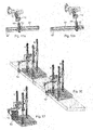
- FIG. 7 shows measurements suitable for main axis calibration.
- FIGS. 8 a - b shows measurements suitable for wrist calibration.
- FIG. 9 shows measurements suitable for fixture calibration.
- FIGS. 10 a - b show measurements suitable for gripper calibration.
- FIGS. 11 a - b show vision system calibration.
- FIGS. 12 and 13 a - b show calibration of discrete sensors.
- FIGS. 14 a - b show calibration of a rotating axis.
- FIGS. 15 a - b and 16 show calibration of a linear axis.
- FIG. 17 shows definition of forbidden zones.
- a parallel kinematic manipulator is defined as a manipulator comprising at least one stationary element, a movable element, denoted a platform, and at least two arms. Each arm comprises a link arrangement connected to the movable platform. Each arm is actuated by a driving means preferably arranged on the stationary element to reduce the moving mass. These link arrangements transfer forces to the movable platform.
- a fully built-up parallel kinematic manipulator for movement of the platform with three degrees of freedom, e.g. in directions x, y and z in a Cartesian system of coordinates three parallel-working arms are required.
- FIGS. 1 a - c show examples of robot components which can be delivered directly from the component manufacturer to the end customer.
- FIG. 1 a shows three linear tracks 1 - 3 , which define linear axes for the robot.
- the wires are attached to a weight with the purpose of compensating for gravity to reduce the actuator power needed.
- FIG. 1 b shows links 10 of the robot
- FIG. 1 d shows a wrist 11 , having a tool flange 12 , in the following de-noted a wrist flange
- FIG. 1 c shows joint mounting structures mounted on the carriages.
- One of the mounting structures is provided with a platform 13 .
- FIG. 2 shows the manipulator when it has been assembled.
- Each carriage 4 is connected to the platform 13 by means of an arm.
- Each arm comprises one or more parallel links 10 .
- the manipulator shown in FIG. 2 has three arms each movable about a linear axis.
- the manipulator has three linear main axes, which are defined by the three linear tracks 1 - 3 .
- each linear track is provided with a position measuring device, which is adapted to measure the position of the carriage relative to the linear track. Usually this measurement is made by the measurement of the shaft angle of the motor driving a ball screw or a rack and pinion carriage.
- the wrist 11 is mounted on the platform 13 .
- the wrist is movable about a plurality of rotational wrist axes.
- the number of wrist axes can be one, two, or three.
- the manipulator shown in FIG. 3 a has two wrist axes.
- the wrist is provided with an angle measuring devices, for example in the form of encoders or resolvers indicating the angular positions of the wrist axis.
- the robot also comprises a control unit 14 including processing means 14 a , such as a CPU, and memory means 14 b , for storing data, robot programs and other software modules.
- the control unit is adapted to receive measurements from the measuring devices.
- the first task is to calibrate the structure.
- the first step of the method is to measure a plurality of measuring points on the surface of a geometrical structure on or in the vicinity of the robot.
- the geometrical structure must have a known geometrical model, for example a CAD-model.
- the geometrical structure is the linear tracks 1 - 3 of the manipulator.
- the CAD-models for the linear tracks are already known from the production stage of the tracks.
- the CAD models may comprise triangles approximating the surfaces of the objects, or a more accurate description of the surfaces using surface splines. Splines are a number of polynomials that describe small parts of a surface and these polynomials are fused together to obtain a continuity when describing the whole surface.
- a measuring tip 15 for example a rigid stylus, is mounted on the wrist flange 12 of the wrist, as shown in FIG. 3 a .
- the measuring tip 15 is moved over the surfaces of the three linear tracks 1 - 3 to collect the geometrical information necessary to identify some of kinematic parameters of the manipulator.
- FIG. 3 b shows how the measuring tip 15 is moved over two surfaces of one of the linear tracks 1 .
- FIG. 3 b also shows the measuring points 18 .
- the positions of the actuators are read and stored by means of the angle measuring devices.
- the figure just shows examples of linear track geometries that are used. For a complete manipulator calibration more geometrical features may be needed.
- the most important kinematic parameters to be identified are the positions and orientations of the actuator paths since these will depend on the installation.
- the lengths of the links could be measured or controlled during manufacturing and could be provided by the component manufacturer.
- the kinematic parameters of the manipulator are estimated based on the stored measurements.
- the calculated measurement points on the surfaces of the linear geometrical structure (calculated by means of the kinematic model with estimated parameters) are used to make best fit to the geometrical model of the geometrical structure.
- adaption of the kinematic parameters of the manipulator are optimized.
- Estimation of the kinematic parameters includes calculating the positions of the measuring tip based on the stored positions of the actuators and a kinematic model of the robot. The identification of kinematic parameters for manipulators are well known.
- the forward kinematic model K fwd is a function of m unknown kinematic parameters a 1 , a 2 , . . . am, such as actuator positions and orientations, link lengths and link mounting positions on the actuator carriages and on the manipulated platform: K fwd ( a 1 , a 2 , . . . am, q 1 , q 2 , . . , q 5) where
- q 1 , q 2 , q 3 are the actuator positions for the linear tracks
- q 4 , q 5 are the angle positions for the wrist.
- n is the number of registrations on the surfaces
- m is the number of kinematics parameters to be identified
- qij is the position registration on actuator i at measuring tip position j on the reference object surfaces.
- Kfwd The mathematical description of Kfwd is known and the next step is to find its parameters a 1 , a 2 , . . . am.
- CAD model for example with surface spline descriptions of the surfaces of the reference object
- a best fit is made of the kinematics parameters a 1 , a 2 . . . am to generate positions X i , Y i , Z i that are all on the theoretical reference object surface with the minimum deviation distribution, for example in a least square sense.
- X i , Y i , Z i positions that are all on the theoretical reference object surface with the minimum deviation distribution, for example in a least square sense.
- several surfaces and reference objects could be used to make it possible to identify all the kinematics parameters.
- the procedure may consist of iterative adjustments of the kinematics parameters until matches are obtained between all CAD model surfaces and positions obtained from the identified kinematics parameters.
- FIG. 4 shows a calibration object 20 mounted on the linear track 1 in order to improve the measurements.
- the measuring tip 15 is then moved over the surfaces as shown in FIG. 4 with different orientation on the measuring tip 15 .
- the main axes could be force manipulated while the wrist axes are controlled to have a fixed orientation of the measuring tip for each surface measurement 22 .
- the estimation of the kinematic parameters, including the best fit calculations, is performed by a calibration module including software instruction for carrying out the necessary calculations.
- this software module is stored in the memory means 14 b of the robot control unit 14 and the software instructions are executed by the processing means 14 a of the control unit.
- a geometrical structure 23 having four spheres with known radius and position relative each other are used for the calibration.
- the geometrical structure is placed at different places in the robot workspace to be able to identify all the kinematic parameters.
- the measurements on the object are made by moving the measuring tip over the surfaces with force manipulation of the robot. In the figure a robot with three degrees of freedom is used.
- the measuring tip 15 can be mounted fixed to the linear track, or on some other object in the vicinity of the manipulator, as shown in FIG. 6 a - b.
- a geometrical structure in the form of a calibration object 24 is mounted on the wrist flange 12 and the calibration object is moved around to measure surface points on its surface.
- the main axes should be force manipulated while the wrist is controlled to have a fixed orientation.
- Best fit of calibration geometry and manipulator kinematics is made at different wrist orientations to get a redundant equation system.
- more than one measurement tips could be mounted in the workspace of the manipulator. In that case, it could also be possible to use the wrist flange 12 itself as the geometrical structure. It should be noted that the measurements are made during movements of the surfaces over the measuring tips since the reference object is on the robot, which will also be very fast.
- a first arrangement including one measuring tip 26 , is mounted fixed in space and is used for carrying out measurements on geometries on the actuated platform.
- a second arrangement 27 including two measuring tips for measurements on the front linear tracks is mounted on the platform.
- a third arrangement 28 including one measuring tip, for measuring on the rear linear track, is mounted on the carriage of one of the front linear tracks. If calibration objects are placed inside the workspace, one measuring tip could be enough, especially if calibration with a fixed measuring tip also is made. Fixed measuring tip and big calibration geometry on the actuated platform could be very efficient.
- the kinematic parameters of the manipulator are calculated by best fit of geometry models to the measured geometries. Since no wrist is in the kinematics, fewer parameters need to be calculated in this case.
- FIGS. 8 a - b If the main axes have been calibrated separately, and the wrist is then mounted on the actuated platform, the wrist could be calibrated relative to the actuated platform, as shown in FIGS. 8 a - b .
- geometries are measured on the manipulated platform 13 , FIG. 8 a , and then a geometry on the wrist flange 12 is measured, FIG. 8 b .
- the geometry on the wrist flange is measured at different wrist orientations (compare FIG. 6 a - b ) to identify the wrist kinematics.
- FIG. 9 shows an example of calibration on a fixture 30 .
- a measuring tip is mounted on the wrist flange or on the tool and the operator moves the measuring tip over surfaces of the fixture. If a geometrical model already exists of the fixture, this model is used to make best fit and calculate the position and orientation of the fixture. If no model exists, as many surfaces as possible on the fixture are measured and a geometrical fixture model is built up (for example with spline surfaces). When later a fixture exchange is made and after that the measured fixture is inserted again, the manipulator can measure the same points again and calculate the new position and orientation of the fixture. In this way it will not be necessary to have an accurate fixture mounting. Every time the fixture is mounted, some of its surfaces will be measured, either manually or by a program, generated the first time when the measurement movements were made.
- FIGS. 10 a - b show measurements 32 , 34 suitable for gripper calibration.
- a gripper 35 on the wrist flange 12 can be calibrated in the same way as the wrist.
- FIGS. 10 a - b show an indirect measurement, where the gripper holds a calibration object 37 on which surfaces are measured.
- the wrist flange geometry is measured and then the geometry of the calibration object 37 .
- FIG. 10 a shows measurements 32 on the wrist flange 12
- FIG. 10 b shows measurements 42 on the calibration object 37 .
- the manipulator is programmed to grip the object, the necessary wrist flange position and orientation, that the manipulator must obtain, can then be calculated.
- FIGS. 11 a - b show vision system calibration.
- the best fit concept can also be used for the calibration of a vision system without working with a vision programming tool.
- the calibration object 37 is placed in the range for a vision system 39 and the robot is used to measure surfaces on the calibration object. These surfaces are then correlated to the object information given by the vision system (in the figure a stereo vision system) and the vision system will be able to measure the position and orientation of the object in the robot coordinate system without any calibration or teach in of the vision system.
- the vision system will calculate the position and orientation of the object and based on the gripper calibration in FIG.
- the robot it will be possible for the robot to grip the object with the information coming from the vision system.
- the same principle could be used to calibrate and program a vision system mounted on the robot arm.
- it could be simplest to measure the surfaces of the calibration object when it is gripped, as shown in FIG. 11 b , by moving the surfaces against a measuring tip fixed in the cell.
- FIGS. 12 and 13 a - b show calibration of discrete sensors.
- the calibration using geometrical features is the same for a sensor 40 (exemplified with an LVDT in the figure) as for a tool. What will be added is a measurement of the measurement range.
- FIG. 12 shows the case when the sensor 40 is mounted on the wrist flange 12 .
- the geometrical calibration is made by means of a measuring tip 15 fixed to the environment and the measurement range is calibrated with a plate 42 which has earlier been calibrated as any object (compare FIG. 9 ) fixed to the environment.
- the geometry is calibrated as shown in FIGS. 13 a - b and the measurement range is calibrated using the already calibrated wrist flange geometry.
- FIGS. 14 a - b show calibration of an optional manipulator including a rotating optional axis 44 and a rotating table 48 .
- Calibration of the rotating optional axis 44 fixed in the cell can be made by mounting a calibration object 46 on the rotating table 48 and then measure object surfaces at two different angles of the table, as shown in the figures. If there are enough geometrical features on the table itself, the calibration could be made using the table geometry. Another possibility is to use the geometrical features of a fixture mounted on the table (compare FIG. 9 ). If the optional manipulator has two axes both axes must be rotated giving at least four poses for the calibration object and thus four complete measurements of the surfaces. If the optional axis is mounted on the robot flange it will be possible to use the same method as used for the wrist calibration.
- FIGS. 15 a - b show calibration of an optional manipulator including a linear optional axis 50 and a moving table 52 .
- Calibration of the linear optional axis 50 fixed in the robot cell, can also be made by mounting a calibration object 46 on the moving table and then measuring object surfaces at two different positions of the table. If there are enough geometrical features on the table itself the calibration could be made using the table geometry. Another possibility is to use the geometrical features of a fixture mounted on the table (compare FIG. 9 ). If the optional manipulator has two axes, both axes must be moved giving at least four poses for the calibration object and thus four complete measurements of the surfaces. The same calibration method can be used for the calibration of a conveyor.
- Calibration of a linear optional axis (track) fixed in the cell and carrying the manipulator can be made by mounting calibration objects 54 , 56 on the fixed part of the track and measuring the object surfaces at least at two different positions of the manipulator, as shown in FIG. 16 .
- FIG. 17 shows a definition of forbidden zones. Obstacles 58 in the workspace can simply be defined by moving a measuring tip 15 over the surfaces of the obstacle. This system will then calculate the forbidden zone for the robot and use it during the execution of robot programs. The measurements are the same as for any object in the workspace and can also be used to calibrate, for example, fixed tables used for loading/unloading operations.
Abstract
Description
K fwd(a1, a2, . . . am, q1, q2, . . , q5)
where
(X 1 , Y 1 , Z 1)=K fwd(a1, a2, . . . am, q 11 , q 21 , . . . , q 51)
(X 2 , Y 2 , Z 2)=K fwd(a1, a2, . . . am, q 12 , q 22 , . . . , q 52)
(X n , Y n , Z n)=K fwd(a1, a2, . . . am, q 1n , q 2n , . . . , q 5n)
where n is the number of registrations on the surfaces, m is the number of kinematics parameters to be identified, and qij is the position registration on actuator i at measuring tip position j on the reference object surfaces.
Claims (22)
Priority Applications (1)
| Application Number | Priority Date | Filing Date | Title |
|---|---|---|---|
| US11/885,234 US7756608B2 (en) | 2005-02-28 | 2006-02-21 | System for calibration of an industrial robot and a method thereof |
Applications Claiming Priority (3)
| Application Number | Priority Date | Filing Date | Title |
|---|---|---|---|
| US65654305P | 2005-02-28 | 2005-02-28 | |
| US11/885,234 US7756608B2 (en) | 2005-02-28 | 2006-02-21 | System for calibration of an industrial robot and a method thereof |
| PCT/EP2006/060140 WO2006089887A2 (en) | 2005-02-28 | 2006-02-21 | A system for calibration of an industrial robot and a method thereof |
Publications (2)
| Publication Number | Publication Date |
|---|---|
| US20080201015A1 US20080201015A1 (en) | 2008-08-21 |
| US7756608B2 true US7756608B2 (en) | 2010-07-13 |
Family
ID=36699031
Family Applications (1)
| Application Number | Title | Priority Date | Filing Date |
|---|---|---|---|
| US11/885,234 Expired - Fee Related US7756608B2 (en) | 2005-02-28 | 2006-02-21 | System for calibration of an industrial robot and a method thereof |
Country Status (2)
| Country | Link |
|---|---|
| US (1) | US7756608B2 (en) |
| WO (1) | WO2006089887A2 (en) |
Cited By (13)
| Publication number | Priority date | Publication date | Assignee | Title |
|---|---|---|---|---|
| US20060258938A1 (en) * | 2005-05-16 | 2006-11-16 | Intuitive Surgical Inc. | Methods and system for performing 3-D tool tracking by fusion of sensor and/or camera derived data during minimally invasive robotic surgery |
| US20090088897A1 (en) * | 2007-09-30 | 2009-04-02 | Intuitive Surgical, Inc. | Methods and systems for robotic instrument tool tracking |
| US20130079928A1 (en) * | 2011-09-28 | 2013-03-28 | Universal Robots A/S | Calibration and Programming of Robots |
| US20130238127A1 (en) * | 2012-03-06 | 2013-09-12 | Jtekt Corporation | Calibration method and calibration system for robot |
| US8792963B2 (en) | 2007-09-30 | 2014-07-29 | Intuitive Surgical Operations, Inc. | Methods of determining tissue distances using both kinematic robotic tool position information and image-derived position information |
| US20150081100A1 (en) * | 2011-07-25 | 2015-03-19 | Johannes Gottlieb | Method for calibrating kinematics |
| US9061421B2 (en) | 2011-03-14 | 2015-06-23 | Matthew E. Trompeter | Robotic work object cell calibration method |
| US10195746B2 (en) | 2014-09-26 | 2019-02-05 | Teradyne, Inc. | Grasping gripper |
| US10399232B2 (en) | 2014-03-04 | 2019-09-03 | Universal Robots A/S | Safety system for industrial robot |
| US10850393B2 (en) | 2015-07-08 | 2020-12-01 | Universal Robots A/S | Method for extending end user programming of an industrial robot with third party contributions |
| US11474510B2 (en) | 2016-04-12 | 2022-10-18 | Universal Robots A/S | Programming a robot by demonstration |
| US11822355B2 (en) | 2010-11-16 | 2023-11-21 | Universal Robot A/S | Programmable robot |
| US11911915B2 (en) | 2021-06-09 | 2024-02-27 | Intrinsic Innovation Llc | Determining robotic calibration processes |
Families Citing this family (16)
| Publication number | Priority date | Publication date | Assignee | Title |
|---|---|---|---|---|
| JP4638327B2 (en) * | 2005-10-17 | 2011-02-23 | 新日本工機株式会社 | Parallel mechanism device, parallel mechanism device calibration method, calibration program, and recording medium |
| US7938602B2 (en) | 2006-03-31 | 2011-05-10 | Jtekt Corporation | Three degree of freedom parallel mechanism, multi-axis control machine tool using the mechanism and control method for the mechanism |
| JP5448326B2 (en) * | 2007-10-29 | 2014-03-19 | キヤノン株式会社 | Gripping device and gripping device control method |
| WO2009089010A2 (en) | 2008-01-10 | 2009-07-16 | Parata Systems, Llc | System and method for calibrating an automated materials handling system |
| CN102216037B (en) * | 2008-11-19 | 2014-06-18 | Abb技术有限公司 | A method and a device for optimizing a programmed movement path for an industrial robot |
| DE102013102651A1 (en) * | 2013-03-14 | 2014-09-18 | Robotics Technology Leaders Gmbh | System and method for absolute calibration of a manipulator |
| CA2978520C (en) * | 2015-03-23 | 2023-01-17 | National Research Council Of Canada | Multi-jointed robot deviation under load determination |
| US9744665B1 (en) * | 2016-01-27 | 2017-08-29 | X Development Llc | Optimization of observer robot locations |
| WO2018024322A1 (en) * | 2016-08-02 | 2018-02-08 | Brainlab Ag | Solid-joint deformation-model verification |
| JP6490112B2 (en) * | 2017-01-17 | 2019-03-27 | ファナック株式会社 | Robot controller |
| DE102017004433B4 (en) * | 2017-05-08 | 2019-03-14 | Kuka Deutschland Gmbh | robot mastering |
| JP7109161B2 (en) * | 2017-06-13 | 2022-07-29 | 川崎重工業株式会社 | Mechanism Model Parameter Estimation Method for Articulated Robots |
| WO2020169212A1 (en) * | 2019-02-22 | 2020-08-27 | Abb Schweiz Ag | Delta robot calibration methods, control system, delta robot and robot system |
| NL2022874B1 (en) * | 2019-04-05 | 2020-10-08 | Vmi Holland Bv | Calibration tool and method |
| CN111421542B (en) * | 2020-04-03 | 2023-02-10 | 重庆固高科技长江研究院有限公司 | Tool center point pose calculation method and control method of robot end clamp |
| CN115363769A (en) * | 2022-10-27 | 2022-11-22 | 北京壹点灵动科技有限公司 | Method and device for measuring precision of surgical robot, storage medium and processor |
Citations (6)
| Publication number | Priority date | Publication date | Assignee | Title |
|---|---|---|---|---|
| US5177563A (en) | 1989-02-01 | 1993-01-05 | Texas A&M University System | Method and apparatus for locating physical objects |
| EP0533949A1 (en) | 1991-04-09 | 1993-03-31 | Kabushiki Kaisha Yaskawa Denki | Calibration system for industrial robot |
| US6366831B1 (en) | 1993-02-23 | 2002-04-02 | Faro Technologies Inc. | Coordinate measurement machine with articulated arm and software interface |
| US6587802B1 (en) * | 1998-09-17 | 2003-07-01 | Dr. Johannes Heidenhain Gmbh | Calibration device for a parallel kinematic manipulator |
| WO2004071717A1 (en) | 2003-02-13 | 2004-08-26 | Abb Ab | A method and a system for programming an industrial robot to move relative to defined positions on an object, including generation of a surface scanning program |
| WO2004076132A2 (en) | 2003-02-28 | 2004-09-10 | Faude, Dieter | Parallel robots for tools |
-
2006
- 2006-02-21 WO PCT/EP2006/060140 patent/WO2006089887A2/en not_active Application Discontinuation
- 2006-02-21 US US11/885,234 patent/US7756608B2/en not_active Expired - Fee Related
Patent Citations (6)
| Publication number | Priority date | Publication date | Assignee | Title |
|---|---|---|---|---|
| US5177563A (en) | 1989-02-01 | 1993-01-05 | Texas A&M University System | Method and apparatus for locating physical objects |
| EP0533949A1 (en) | 1991-04-09 | 1993-03-31 | Kabushiki Kaisha Yaskawa Denki | Calibration system for industrial robot |
| US6366831B1 (en) | 1993-02-23 | 2002-04-02 | Faro Technologies Inc. | Coordinate measurement machine with articulated arm and software interface |
| US6587802B1 (en) * | 1998-09-17 | 2003-07-01 | Dr. Johannes Heidenhain Gmbh | Calibration device for a parallel kinematic manipulator |
| WO2004071717A1 (en) | 2003-02-13 | 2004-08-26 | Abb Ab | A method and a system for programming an industrial robot to move relative to defined positions on an object, including generation of a surface scanning program |
| WO2004076132A2 (en) | 2003-02-28 | 2004-09-10 | Faude, Dieter | Parallel robots for tools |
Non-Patent Citations (2)
| Title |
|---|
| PCT/ISA/210-International Search Report-Nov. 27, 2006. |
| PCT/ISA/237-Written Opinion of the International Searching Authority-Nov. 27, 2006. |
Cited By (28)
| Publication number | Priority date | Publication date | Assignee | Title |
|---|---|---|---|---|
| US10842571B2 (en) | 2005-05-16 | 2020-11-24 | Intuitive Surgical Operations, Inc. | Methods and system for performing 3-D tool tracking by fusion of sensor and/or camera derived data during minimally invasive robotic surgery |
| US20060258938A1 (en) * | 2005-05-16 | 2006-11-16 | Intuitive Surgical Inc. | Methods and system for performing 3-D tool tracking by fusion of sensor and/or camera derived data during minimally invasive robotic surgery |
| US11672606B2 (en) | 2005-05-16 | 2023-06-13 | Intuitive Surgical Operations, Inc. | Methods and system for performing 3-D tool tracking by fusion of sensor and/or camera derived data during minimally invasive robotic surgery |
| US11478308B2 (en) | 2005-05-16 | 2022-10-25 | Intuitive Surgical Operations, Inc. | Methods and system for performing 3-D tool tracking by fusion of sensor and/or camera derived data during minimally invasive robotic surgery |
| US10555775B2 (en) | 2005-05-16 | 2020-02-11 | Intuitive Surgical Operations, Inc. | Methods and system for performing 3-D tool tracking by fusion of sensor and/or camera derived data during minimally invasive robotic surgery |
| US11116578B2 (en) | 2005-05-16 | 2021-09-14 | Intuitive Surgical Operations, Inc. | Methods and system for performing 3-D tool tracking by fusion of sensor and/or camera derived data during minimally invasive robotic surgery |
| US10792107B2 (en) | 2005-05-16 | 2020-10-06 | Intuitive Surgical Operations, Inc. | Methods and system for performing 3-D tool tracking by fusion of sensor and/or camera derived data during minimally invasive robotic surgery |
| US20090088897A1 (en) * | 2007-09-30 | 2009-04-02 | Intuitive Surgical, Inc. | Methods and systems for robotic instrument tool tracking |
| US8108072B2 (en) * | 2007-09-30 | 2012-01-31 | Intuitive Surgical Operations, Inc. | Methods and systems for robotic instrument tool tracking with adaptive fusion of kinematics information and image information |
| US8792963B2 (en) | 2007-09-30 | 2014-07-29 | Intuitive Surgical Operations, Inc. | Methods of determining tissue distances using both kinematic robotic tool position information and image-derived position information |
| US11822355B2 (en) | 2010-11-16 | 2023-11-21 | Universal Robot A/S | Programmable robot |
| US9061421B2 (en) | 2011-03-14 | 2015-06-23 | Matthew E. Trompeter | Robotic work object cell calibration method |
| US9266241B2 (en) | 2011-03-14 | 2016-02-23 | Matthew E. Trompeter | Robotic work object cell calibration system |
| US20150081100A1 (en) * | 2011-07-25 | 2015-03-19 | Johannes Gottlieb | Method for calibrating kinematics |
| US9833897B2 (en) | 2011-09-28 | 2017-12-05 | Universal Robots A/S | Calibration and programming of robots |
| CN103889663A (en) * | 2011-09-28 | 2014-06-25 | Ur机器人有限公司 | Calibration and programming of robots |
| US20130079928A1 (en) * | 2011-09-28 | 2013-03-28 | Universal Robots A/S | Calibration and Programming of Robots |
| CN104991518B (en) * | 2011-09-28 | 2018-10-09 | Ur机器人有限公司 | The calibration and programming of robot |
| CN103889663B (en) * | 2011-09-28 | 2016-09-28 | Ur机器人有限公司 | The calibration of robot and programming |
| US9248573B2 (en) * | 2011-09-28 | 2016-02-02 | Universal Robots A/S | Calibration and programming of robots |
| CN104991518A (en) * | 2011-09-28 | 2015-10-21 | Ur机器人有限公司 | Calibration and programming of robots |
| US9014853B2 (en) * | 2012-03-06 | 2015-04-21 | Jtekt Corporation | Calibration method and calibration system for robot |
| US20130238127A1 (en) * | 2012-03-06 | 2013-09-12 | Jtekt Corporation | Calibration method and calibration system for robot |
| US10399232B2 (en) | 2014-03-04 | 2019-09-03 | Universal Robots A/S | Safety system for industrial robot |
| US10195746B2 (en) | 2014-09-26 | 2019-02-05 | Teradyne, Inc. | Grasping gripper |
| US10850393B2 (en) | 2015-07-08 | 2020-12-01 | Universal Robots A/S | Method for extending end user programming of an industrial robot with third party contributions |
| US11474510B2 (en) | 2016-04-12 | 2022-10-18 | Universal Robots A/S | Programming a robot by demonstration |
| US11911915B2 (en) | 2021-06-09 | 2024-02-27 | Intrinsic Innovation Llc | Determining robotic calibration processes |
Also Published As
| Publication number | Publication date |
|---|---|
| US20080201015A1 (en) | 2008-08-21 |
| WO2006089887A3 (en) | 2007-01-11 |
| WO2006089887A2 (en) | 2006-08-31 |
Similar Documents
| Publication | Publication Date | Title |
|---|---|---|
| US7756608B2 (en) | System for calibration of an industrial robot and a method thereof | |
| CN108748159B (en) | Self-calibration method for tool coordinate system of mechanical arm | |
| CN107995885B (en) | Coordinate system calibration method, system and device | |
| EP2547490B1 (en) | Calibration of a base coordinate system for an industrial robot | |
| US20200298411A1 (en) | Method for the orientation of an industrial robot, and industrial robot | |
| Groom et al. | Real-time failure-tolerant control of kinematically redundant manipulators | |
| US4698572A (en) | Kinematic parameter identification for robotic manipulators | |
| KR101797122B1 (en) | Method for Measurement And Compensation of Error on Portable 3D Coordinate Measurement Machine | |
| WO2015070010A1 (en) | Calibration system and method for calibrating industrial robot | |
| WO2018196232A1 (en) | Method for automatically calibrating robot and end effector, and system | |
| JP3349652B2 (en) | Offline teaching method | |
| US20220105640A1 (en) | Method Of Calibrating A Tool Of An Industrial Robot, Control System And Industrial Robot | |
| Santolaria et al. | Self-alignment of on-board measurement sensors for robot kinematic calibration | |
| CN111775145A (en) | Control system of series-parallel robot | |
| US11524407B2 (en) | Robot system and operating method thereof | |
| US11554494B2 (en) | Device for acquiring a position and orientation of an end effector of a robot | |
| JPH06131032A (en) | Robot device and teaching method for robot device | |
| JPH0445841B2 (en) | ||
| JP5786550B2 (en) | 6-axis robot offset detection method | |
| Gümbel et al. | Precision optimized pose and trajectory planning for vertically articulated robot arms | |
| Sawyer et al. | Improving robotic accuracy through iterative teaching | |
| Ishii et al. | A new approach to improve absolute positioning accuracy of robot manipulators | |
| Liu et al. | An automated method to calibrate industrial robot joint offset using virtual line-based single-point constraint approach | |
| JP2021186929A (en) | Control method for multi-axis robot | |
| CN109968347B (en) | Zero calibration method of seven-axis robot |
Legal Events
| Date | Code | Title | Description |
|---|---|---|---|
| AS | Assignment |
Owner name: ABB AB, SWEDEN Free format text: ASSIGNMENT OF ASSIGNORS INTEREST;ASSIGNOR:BROGARDH, TORGNY;REEL/FRAME:019800/0214 Effective date: 20070613 |
|
| FEPP | Fee payment procedure |
Free format text: PAYOR NUMBER ASSIGNED (ORIGINAL EVENT CODE: ASPN); ENTITY STATUS OF PATENT OWNER: LARGE ENTITY |
|
| FEPP | Fee payment procedure |
Free format text: PAYOR NUMBER ASSIGNED (ORIGINAL EVENT CODE: ASPN); ENTITY STATUS OF PATENT OWNER: LARGE ENTITY Free format text: PAYER NUMBER DE-ASSIGNED (ORIGINAL EVENT CODE: RMPN); ENTITY STATUS OF PATENT OWNER: LARGE ENTITY |
|
| FPAY | Fee payment |
Year of fee payment: 4 |
|
| FEPP | Fee payment procedure |
Free format text: MAINTENANCE FEE REMINDER MAILED (ORIGINAL EVENT CODE: REM.) |
|
| AS | Assignment |
Owner name: ABB SCHWEIZ AG, SWITZERLAND Free format text: ASSIGNMENT OF ASSIGNORS INTEREST;ASSIGNOR:ABB AB;REEL/FRAME:045713/0398 Effective date: 20171024 |
|
| LAPS | Lapse for failure to pay maintenance fees |
Free format text: PATENT EXPIRED FOR FAILURE TO PAY MAINTENANCE FEES (ORIGINAL EVENT CODE: EXP.) |
|
| STCH | Information on status: patent discontinuation |
Free format text: PATENT EXPIRED DUE TO NONPAYMENT OF MAINTENANCE FEES UNDER 37 CFR 1.362 |
|
| FP | Lapsed due to failure to pay maintenance fee |
Effective date: 20180713 |