US7755747B2 - Device and method for checking the authenticity of an anti-forgery marking - Google Patents
Device and method for checking the authenticity of an anti-forgery marking Download PDFInfo
- Publication number
- US7755747B2 US7755747B2 US10/528,446 US52844605A US7755747B2 US 7755747 B2 US7755747 B2 US 7755747B2 US 52844605 A US52844605 A US 52844605A US 7755747 B2 US7755747 B2 US 7755747B2
- Authority
- US
- United States
- Prior art keywords
- light sources
- light
- angle
- intensities
- measuring
- Prior art date
- Legal status (The legal status is an assumption and is not a legal conclusion. Google has not performed a legal analysis and makes no representation as to the accuracy of the status listed.)
- Expired - Fee Related, expires
Links
- 238000000034 method Methods 0.000 title claims description 24
- 239000003086 colorant Substances 0.000 claims abstract description 33
- 230000003595 spectral effect Effects 0.000 claims abstract description 14
- 238000005259 measurement Methods 0.000 claims description 22
- 239000000835 fiber Substances 0.000 claims description 7
- 238000005286 illumination Methods 0.000 claims description 7
- 230000001678 irradiating effect Effects 0.000 claims 2
- 238000005516 engineering process Methods 0.000 description 8
- 238000001228 spectrum Methods 0.000 description 7
- 238000010521 absorption reaction Methods 0.000 description 6
- 229910052751 metal Inorganic materials 0.000 description 5
- 239000002184 metal Substances 0.000 description 5
- 229910052782 aluminium Inorganic materials 0.000 description 3
- XAGFODPZIPBFFR-UHFFFAOYSA-N aluminium Chemical compound [Al] XAGFODPZIPBFFR-UHFFFAOYSA-N 0.000 description 3
- 238000009826 distribution Methods 0.000 description 3
- 230000006870 function Effects 0.000 description 3
- 239000000463 material Substances 0.000 description 3
- 239000004417 polycarbonate Substances 0.000 description 3
- 229920000515 polycarbonate Polymers 0.000 description 3
- -1 polyethylene Polymers 0.000 description 3
- 238000012545 processing Methods 0.000 description 3
- XEEYBQQBJWHFJM-UHFFFAOYSA-N Iron Chemical compound [Fe] XEEYBQQBJWHFJM-UHFFFAOYSA-N 0.000 description 2
- PXHVJJICTQNCMI-UHFFFAOYSA-N Nickel Chemical compound [Ni] PXHVJJICTQNCMI-UHFFFAOYSA-N 0.000 description 2
- IOVCWXUNBOPUCH-UHFFFAOYSA-M Nitrite anion Chemical compound [O-]N=O IOVCWXUNBOPUCH-UHFFFAOYSA-M 0.000 description 2
- KDLHZDBZIXYQEI-UHFFFAOYSA-N Palladium Chemical compound [Pd] KDLHZDBZIXYQEI-UHFFFAOYSA-N 0.000 description 2
- 239000004698 Polyethylene Substances 0.000 description 2
- 239000004642 Polyimide Substances 0.000 description 2
- 239000004743 Polypropylene Substances 0.000 description 2
- 238000004040 coloring Methods 0.000 description 2
- 238000010586 diagram Methods 0.000 description 2
- 230000000694 effects Effects 0.000 description 2
- 239000011888 foil Substances 0.000 description 2
- PCHJSUWPFVWCPO-UHFFFAOYSA-N gold Chemical compound [Au] PCHJSUWPFVWCPO-UHFFFAOYSA-N 0.000 description 2
- 229910052737 gold Inorganic materials 0.000 description 2
- 239000010931 gold Substances 0.000 description 2
- 230000003993 interaction Effects 0.000 description 2
- 238000013208 measuring procedure Methods 0.000 description 2
- 229910044991 metal oxide Inorganic materials 0.000 description 2
- 150000004706 metal oxides Chemical class 0.000 description 2
- BASFCYQUMIYNBI-UHFFFAOYSA-N platinum Chemical compound [Pt] BASFCYQUMIYNBI-UHFFFAOYSA-N 0.000 description 2
- 229920000573 polyethylene Polymers 0.000 description 2
- 229920000139 polyethylene terephthalate Polymers 0.000 description 2
- 239000005020 polyethylene terephthalate Substances 0.000 description 2
- 229920001721 polyimide Polymers 0.000 description 2
- 229920000642 polymer Polymers 0.000 description 2
- 229920000193 polymethacrylate Polymers 0.000 description 2
- 229920001155 polypropylene Polymers 0.000 description 2
- 229920002635 polyurethane Polymers 0.000 description 2
- 239000004814 polyurethane Substances 0.000 description 2
- 238000011158 quantitative evaluation Methods 0.000 description 2
- 239000010409 thin film Substances 0.000 description 2
- 238000001771 vacuum deposition Methods 0.000 description 2
- VYZAMTAEIAYCRO-UHFFFAOYSA-N Chromium Chemical compound [Cr] VYZAMTAEIAYCRO-UHFFFAOYSA-N 0.000 description 1
- RYGMFSIKBFXOCR-UHFFFAOYSA-N Copper Chemical compound [Cu] RYGMFSIKBFXOCR-UHFFFAOYSA-N 0.000 description 1
- KOOYZQZPDGRCEX-UHFFFAOYSA-L N(=O)[O-].[Sn+2].N(=O)[O-] Chemical compound N(=O)[O-].[Sn+2].N(=O)[O-] KOOYZQZPDGRCEX-UHFFFAOYSA-L 0.000 description 1
- 239000004793 Polystyrene Substances 0.000 description 1
- VYPSYNLAJGMNEJ-UHFFFAOYSA-N Silicium dioxide Chemical compound O=[Si]=O VYPSYNLAJGMNEJ-UHFFFAOYSA-N 0.000 description 1
- BQCADISMDOOEFD-UHFFFAOYSA-N Silver Chemical compound [Ag] BQCADISMDOOEFD-UHFFFAOYSA-N 0.000 description 1
- ATJFFYVFTNAWJD-UHFFFAOYSA-N Tin Chemical compound [Sn] ATJFFYVFTNAWJD-UHFFFAOYSA-N 0.000 description 1
- RTAQQCXQSZGOHL-UHFFFAOYSA-N Titanium Chemical compound [Ti] RTAQQCXQSZGOHL-UHFFFAOYSA-N 0.000 description 1
- NHWNVPNZGGXQQV-UHFFFAOYSA-J [Si+4].[O-]N=O.[O-]N=O.[O-]N=O.[O-]N=O Chemical compound [Si+4].[O-]N=O.[O-]N=O.[O-]N=O.[O-]N=O NHWNVPNZGGXQQV-UHFFFAOYSA-J 0.000 description 1
- 238000000862 absorption spectrum Methods 0.000 description 1
- QLJCFNUYUJEXET-UHFFFAOYSA-K aluminum;trinitrite Chemical compound [Al+3].[O-]N=O.[O-]N=O.[O-]N=O QLJCFNUYUJEXET-UHFFFAOYSA-K 0.000 description 1
- 238000004364 calculation method Methods 0.000 description 1
- 229910052804 chromium Inorganic materials 0.000 description 1
- 239000011651 chromium Substances 0.000 description 1
- 229910017052 cobalt Inorganic materials 0.000 description 1
- 239000010941 cobalt Substances 0.000 description 1
- GUTLYIVDDKVIGB-UHFFFAOYSA-N cobalt atom Chemical compound [Co] GUTLYIVDDKVIGB-UHFFFAOYSA-N 0.000 description 1
- 229910052802 copper Inorganic materials 0.000 description 1
- 239000010949 copper Substances 0.000 description 1
- 238000013461 design Methods 0.000 description 1
- 238000000295 emission spectrum Methods 0.000 description 1
- 238000007646 gravure printing Methods 0.000 description 1
- 230000003760 hair shine Effects 0.000 description 1
- 229910052738 indium Inorganic materials 0.000 description 1
- APFVFJFRJDLVQX-UHFFFAOYSA-N indium atom Chemical compound [In] APFVFJFRJDLVQX-UHFFFAOYSA-N 0.000 description 1
- 229910052742 iron Inorganic materials 0.000 description 1
- 229910052759 nickel Inorganic materials 0.000 description 1
- 230000003287 optical effect Effects 0.000 description 1
- TWNQGVIAIRXVLR-UHFFFAOYSA-N oxo(oxoalumanyloxy)alumane Chemical compound O=[Al]O[Al]=O TWNQGVIAIRXVLR-UHFFFAOYSA-N 0.000 description 1
- 229910052763 palladium Inorganic materials 0.000 description 1
- 238000005240 physical vapour deposition Methods 0.000 description 1
- 229910052697 platinum Inorganic materials 0.000 description 1
- 238000003825 pressing Methods 0.000 description 1
- 238000007639 printing Methods 0.000 description 1
- 229910052814 silicon oxide Inorganic materials 0.000 description 1
- 229910052709 silver Inorganic materials 0.000 description 1
- 239000004332 silver Substances 0.000 description 1
- 238000010183 spectrum analysis Methods 0.000 description 1
- 238000003860 storage Methods 0.000 description 1
- 229910052718 tin Inorganic materials 0.000 description 1
- 239000011135 tin Substances 0.000 description 1
- XOLBLPGZBRYERU-UHFFFAOYSA-N tin dioxide Chemical compound O=[Sn]=O XOLBLPGZBRYERU-UHFFFAOYSA-N 0.000 description 1
- 229910001887 tin oxide Inorganic materials 0.000 description 1
- 239000010936 titanium Substances 0.000 description 1
- 229910052719 titanium Inorganic materials 0.000 description 1
- 239000012780 transparent material Substances 0.000 description 1
Images


Classifications
-
- G—PHYSICS
- G07—CHECKING-DEVICES
- G07D—HANDLING OF COINS OR VALUABLE PAPERS, e.g. TESTING, SORTING BY DENOMINATIONS, COUNTING, DISPENSING, CHANGING OR DEPOSITING
- G07D7/00—Testing specially adapted to determine the identity or genuineness of valuable papers or for segregating those which are unacceptable, e.g. banknotes that are alien to a currency
- G07D7/06—Testing specially adapted to determine the identity or genuineness of valuable papers or for segregating those which are unacceptable, e.g. banknotes that are alien to a currency using wave or particle radiation
- G07D7/12—Visible light, infrared or ultraviolet radiation
- G07D7/1205—Testing spectral properties
-
- G—PHYSICS
- G01—MEASURING; TESTING
- G01J—MEASUREMENT OF INTENSITY, VELOCITY, SPECTRAL CONTENT, POLARISATION, PHASE OR PULSE CHARACTERISTICS OF INFRARED, VISIBLE OR ULTRAVIOLET LIGHT; COLORIMETRY; RADIATION PYROMETRY
- G01J3/00—Spectrometry; Spectrophotometry; Monochromators; Measuring colours
- G01J3/46—Measurement of colour; Colour measuring devices, e.g. colorimeters
- G01J3/50—Measurement of colour; Colour measuring devices, e.g. colorimeters using electric radiation detectors
- G01J3/504—Goniometric colour measurements, for example measurements of metallic or flake based paints
-
- G—PHYSICS
- G07—CHECKING-DEVICES
- G07D—HANDLING OF COINS OR VALUABLE PAPERS, e.g. TESTING, SORTING BY DENOMINATIONS, COUNTING, DISPENSING, CHANGING OR DEPOSITING
- G07D7/00—Testing specially adapted to determine the identity or genuineness of valuable papers or for segregating those which are unacceptable, e.g. banknotes that are alien to a currency
- G07D7/06—Testing specially adapted to determine the identity or genuineness of valuable papers or for segregating those which are unacceptable, e.g. banknotes that are alien to a currency using wave or particle radiation
- G07D7/12—Visible light, infrared or ultraviolet radiation
- G07D7/121—Apparatus characterised by sensor details
Definitions
- the invention relates to a device and a method for checking the authenticity of a forgery-proof marking with colors which change depending on the angle of observation.
- Such markings are used to identify bank notes and other financial products such as securities, checks, admission tickets and similar, as well as for product and brand protection. Such markings are also being used increasingly in security technology. They are used there for example to mark access IDs.
- U.S. Pat. No. 6,285,452 describes a device for measuring colors during which the surface of a sample is irradiated without using light-conducting fiber optics. The light thrown back by the sample is analyzed spectrally. This device also requires expensive spectral-splitting components. It is also not suitable for the measurement of colors which change depending on the angle of observation.
- a forgery-proof marking is known.
- the marking has colors which change depending on the angle of observation. These so-called tilt-angle colors are created by a cluster layer positioned at a specified distance from a metal layer. Tilt-angle colors created like this have a particularly distinct and characteristic spectrum.
- the object of the invention is to eliminate the disadvantages in accordance with the state of technology.
- a device and a method are to be specified with which the authenticity of a forgery-proof marking can be checked easily and inexpensively.
- a device is provided to check the authenticity of a forgery-proof marking with colors which change depending on the angle of observation, with
- the suggested device has a simple design. In particular there are no expensive spectral-splitting components. With the suggested device the light reflected by the surface is not spectrally split up. Instead, light in several different wavelengths is beamed to the surface and their reflected intensities are measured. These are compared with reference intentsities which were previously measured for at least one specified color. Such a device can be implemented with relatively inexpensive, available components.
- second light sources emitting in a specified spectral range wherein the second light sources differ from one another in the wavelength of their emission maximum, and wherein the second light sources in the housing are positioned so that they irradiate the surface at a specified third angle when the housing is placed on top of the surface.
- the provision of second light sources which irradiate the surface at a specified third angle permits the colors to be determined in dependence on the angle of observation. This makes it particularly easy to identify tilt-angle effects as they are particularly used for forgery-proof marking of bank notes or similar.
- a second means located at a fourth angle is provided for the measurement of the intensities of the light reflected by the surface.
- the provision of such a second means of measuring the intensities ensures particularly reliable recognition and determination of the colors. For example it is possible to irradiate the surface via the first light source to determine colors and to acquire the reflected light both with the first and the second means of measuring the intensities of the light reflected by the surface at different angels. This permits a particularly reliable color determination.
- the provision of the second means of measuring the intensities of the reflected light also permits the determination of the colors which change depending on the angle of observation.
- the specified spectral range at half maximum intensity has a width of less than 100 nm, preferably less than 50 nm.
- the width at half maximum intensity is also called the half-value width or full-width-at-half-maximum (FWHM).
- FWHM full-width-at-half-maximum
- the use of light-emitting diodes, lasers or the free ends of the thereby connected light-conducting fibers has been shown to be useful. Light-emitting diodes can also be used which can emit light at different wavelengths. It is advantageous that the means of measuring the intensities has at least one photo diode.
- the first angle is equal to the second angle so that the light irradiated on the surface is measured specularly reflected at the second angle.
- the third angle is equal to the fourth angle so that the light beamed onto the surface at the third angle is measured specularly reflected at the fourth angle. This permits a particularly reliable determination of the colors which change depending on the angle of observation.
- the first and the third angle differ from each other and are located in a range from 5° to 60°, preferably from 15° to 45°. Intensities are reflected under the aforementioned angles which are well suited for measuring.
- a unit is provided for the sequential illumination of the surface with the light sources and for measurement of the particular intensities of the reflected light in a defined sequence.
- the emission maximum of the light sources is in the near UV, in visible or in the IR spectral range.
- Particularly suitable are light sources in the wavelength range from 350 nm to 1000 nm.
- duration of the illumination and the measurement is specified in dependence on the luminance characteristic of each of the light sources and/or the measuring characteristic of the means of measuring the intensities.
- a suitable unit for the control of the duration of illumination and measurement is provided for this.
- the luminosity of the light sources depends to a great extent on the emitted wavelength. To obtain comparable measuring signals, it is useful to adjust the luminance duration of the individual light sources in dependence on their emitted wavelength. In the same way the duration of measurement is adjusted to the measuring characteristic of the means of measuring the intensities.
- mechanical, electronic or technical software units are provided for the offset of background light.
- Background light surrounding light for example, affects the measuring signal.
- surrounding light is screened out as much as possible. It is also possible to consider remaining light which arrives at the means of measuring the intensities when the light sources are off. A so-called dark measurement can be performed either before or after the actual color measurement.
- undesired interference signals such as frequencies of 50 Hz or 100 Hz can be separated from the actual measuring signals with electronic filters or software-supported filters.
- first and/or second light sources are provided.
- the number of light sources which are used affects the accuracy of the color determination. For reasons of space and arrangement, it has been shown to be particularly advantageous to use between 4 and 7 light sources per measuring angle.
- the means is equipped with a micro-controller for automatic comparison or to calculate the coordinates of the color range.
- Reference intensities or coordinates of the color area can be stored on the micro-controller and compared with the measured values.
- an indication device preferably a display or one or more additional light-emitting diodes, is provided to indicate the result determined by the comparison.
- the indication device can also be integrated in an external unit such as, for example, PDA or laptop which exchanges data with the device via a cable or via wireless connections.
- Such an indication device makes it possible, for instance, to also allocate an origin parameter to an identified tilt-angle color and output this with the indication device. Markings can thus be identified with encrypted information about distribution routes, origin or for logistic purposes in a way which cannot be recognized during transportation.
- a unit for modulation of the light sources is provided to separate the interference signals from the measuring signals.
- the forgery-proof marking has a first layer which reflects electro-magnetic waves and is connected to an object, on which layer an inert second layer with a specified thickness is provided which can be penetrated by electro-magnetic waves, and wherein a third layer created from metallic clusters is applied to the second layer.
- the “object” is the object to be marked, for example, a bank note, a label or similar.
- the suggested marking is particularly resistant to forgery.
- the colors have a characteristic spectrum. It is particularly notable that, when such a marking is reproduced, the same colors can always be observed for the same tilt angles. This makes it possible to automatically check the authenticity of the marking.
- the device as provided by the invention is particularly suited for checking the authenticity of the suggested forgery-proof marking.
- the device provided by the invention and the forgery-proof marking together form a coordinated system or a kit to ensure the authenticity of objects.
- At least one of the layers can have a structure.
- the structure can be a structure in the area like a pattern or a drawing. However it can also be a relief-type structure. In this case, the marking appears in different colors.
- an inert fourth layer is provided which covers the third layer and which can be penetrated by electromagnetic waves.
- the fourth layer is used essentially to protect the covered layers.
- the metallic clusters can be made of silver, gold, platinum, aluminum, copper, tin, iron, cobalt, chromium, nickel, palladium, titanium or indium, for example.
- the second and/or fourth layer can be made of the following materials: metal oxide, metal nitrite, metal carbide, particularly of silicon oxide, silicon nitrite, tin oxide, tin nitrite, aluminum oxide, aluminum nitrite or polymers, in particular polycarbonate (PC), polyethylene (PE), polypropylene (PP), polyurethane (PUR), polyimide (PI), polystyrene (PS), polyethylene terephthalate (PET) or polymethacrylate (PMA). These materials are essentially chemically inert. They are not sensitive to moisture.
- the function of the second layer essentially consists of permanently establishing a specified distance to the third layer and/or a specified structure.
- a unique identifiable coloring is recognizable at a distance of less than 2 ⁇ m between the first and the third layer.
- the coloring depends on the angle of observation and is characteristic.
- the layers will be made at least partially using thin-film technology.
- vacuum coating technologies such as PVD or CVD as well as printing technologies such as gravure printing can be used.
- a method for checking the authenticity of a forgery-proof marking with colors which change depending on the angle of observation consisting of the following steps:
- the suggested method is simple and can be performed without great technical effort. In particular, no expensive spectral-splitting components are required. Notwithstanding, the suggested method permits the reliable determination of the authenticity of forgery-proof markings with colors which change depending on the angle of observation.
- FIG. 1 A schematic cross section view of a measuring head of the device
- FIG. 2 Arrangements of light sources
- FIG. 3 A block circuit diagram of the device
- FIG. 4 Measuring results of the absorption measurements at different angles of illumination
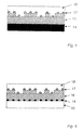
- FIG. 5 A schematic cross section view of a first continuously visible marking
- FIG. 6 A schematic cross section view of a second continuously visible marking
- FIG. 7 Absorption spectrums of a marking as per FIG. 5 at different angles of observation
- FIG. 8 A quantitative evaluation of the spectrums as per FIG. 7 at different wavelengths.
- FIG. 1 shows a measuring head of a device for determination of colors applied to a surface which colors change depending on the angle of observation.
- 1 indicates a group of first light sources with which the measuring point M located on a surface O of the sample can be illuminated at a first angle ⁇ 1 .
- a first photo diode 2 is located at a second angle ⁇ 2 .
- the measuring head contains a group of second light sources 3 at a third angle ⁇ 1 .
- a second photo diode 4 is provided at a fourth angle ⁇ 2 .
- the first angle ⁇ 1 and the second angle ⁇ 2 have the same size on the measuring point M with reference to a normal N.
- the lines related to the two angles as well as the normal N are located in one plane.
- the third angle ⁇ 1 and the fourth angle ⁇ 2 are equal in size with reference to the normal N. Also the lines of these two angles are located in one plane with the normal N.
- Light sources 1 , 3 and photo diodes 2 , 4 are mounted in a common, light-impermeable housing 5 which has a measuring opening 6 in the floor.
- the light-emitting diodes may have an emission spectrum of a half value width of less than 50 nm.
- the emission maximums of the light-emitting diodes each differ from one another. Notwithstanding, it is useful that the first group of light sources 1 and the second group of light sources 2 each have the same number of light-emitting diodes with the same luminance characteristic.
- FIG. 2 shows different arrangements of the first light sources 1 and the second light sources 2 .
- the first light sources 1 can consist of at least 3 and not more than 12 different incandescent elements. It is particularly preferable that the first light sources 1 and the second light sources 2 consist of 7 different incandescent elements.
- the incandescent elements can also be lasers or the one end of light-conducting fibers whose other ends are connected to a light source such as for example a light-emitting diode or a laser.
- FIG. 3 shows a schematic block circuit diagram of the layout of a device provided by the invention.
- a micro-controller 7 is equipped with several inputs/outputs port A, port B, port C, port D, a micro-processor CPU, an analog-digital converter AD/DA, a random access memory RAM, a hard-drive, electrically erasable, programmable, read-only memory EPROM as well as an RS 232 interface and an ICP interface for the connection to external data processing units such as for example a PC.
- the input/output port D is connected via a de-multiplexer 8 with the first light sources 1 and the second light sources 3 .
- the housing 5 has been omitted here for clarity's sake.
- the first photo diode 2 and the second photo diode 4 are connected via an amplifier 9 and a filter 10 with the input/output port A of the micro-controller 7 .
- manual buttons 11 a , 11 b are connected with the input/output port C.
- the other input/output port B is used to connect an indication device 12 or a light-emitting diode.
- 13 shows a power supply unit which can consist of batteries or rechargeable storage batteries and voltage regulators for example.
- the function of the device is the following:
- the flash program memory of the micro-controller contains a specified measuring program.
- the measuring program can be started by pressing the first button 11 a after the housing 5 has been placed on the surface O to be measured. It is useful to first measure the background light via the first photo diode 2 and the second photo diode 4 .
- the measured value is stored by the measuring program in the random access memory RAM.
- the light sources 1 are then turned on in succession for a specified period of time. During the turn-on phase, a measurement of the reflected intensity is performed for each of the light sources 1 using the first photo diode 2 and the second photo diode 4 .
- the measured values are offset using the previously measured values of the background light and also stored in the random access memory RAM.
- the measured values are compared with the reference intensities stored in the EPROM.
- the measuring program determines that the measured color matches the color corresponding to the reference intensities.
- the result is output on the indication device 12 .
- Such reference intensities can be determined for example with a reference measurement of a specified color and then stored.
- reference intensities for a plurality of specified colors can be stored with tilt-angle effects for different channels of distribution.
- the suggested device can then not only be used to detect whether the applicable product is authentic but also whether it was delivered via the correct distribution channel.
- the second key 11 b is pressed to perform a further measurement. In this case the measurement can begin immediately.
- the measured value of the background light which was already determined can be used to offset the measuring results.
- the light sources 1 , 3 are operated with a specified frequency during the turn-on phase.
- the intensities measured by photo diodes 2 , 4 are only included to the extent that they can be measured within the observed frequency window. Interference frequencies caused by artificial light, among others, for example 50 Hz or 100 Hz, can be eliminated in this way. For example all non-modulated signals can be separated from the modulated signals via lock-in technology.
- the device it is useful to install the device in a single housing together with the measuring head so that it is a portable, hand-held device. However it is also possible that the measuring head is connected with a cable to the device.
- the device provided by the invention is only to be used for simple determination of colors on surfaces, it is sufficient to provide first light sources 1 and the first photo diode 2 and/or the second photo diode 4 .
- FIG. 4 shows a comparison of the measuring values of a reader device which works according to the invention and the measured values of a commercially available spectrometer (LIGA micro-spectrometer STEAG microParts).
- the reader device uses an optical head as shown in FIG. 1 and illuminates the surface of each measured tilt color sequentially with light-emitting diodes of the wavelengths 441, 565, 591, 632, 650, 682 and 880 nm. A color changing in dependence on the angle of observation was measured at the angles 18° and 42°. From the intensity measuring values I obtained from this and the maximum reflected intensities I max obtained from an analog measurement on a polished aluminum mirror, the absorption A can be calculated as a percentage.
- A I/I max *100
- the absorption values of the described reader device very closely follow the curve progression of the absorption measured by the spectrometer for both measuring angles.
- a first layer reflecting electro-magnetic waves is designated as 14 .
- This can be a metallic foil, for example an aluminum foil.
- the first layer 14 can also be a layer made of clusters which is applied to a carrier 15 .
- the carrier 15 can be the object to be marked. It is useful when the clusters are made of gold.
- the first layer 14 shown in FIG. 5 can also be the object if its surface is made of a material which reflects electromagnetic waves.
- a chemically inert second layer 16 is applied to the first layer 14 .
- the second layer 16 has a structure.
- the structure is in the form of a relief which, for example, is designed like a barcode. It is advantageous that the thickness of the second layer is between 20 and 1000 nm. It applied via thin-film technology. Vacuum coating methods, for example, are suitable for this.
- a third layer 17 which is made of metallic clusters is applied to the second layer 16 .
- the third layer 17 in turn is covered by a fourth layer 18 .
- the fourth layer 18 protects the layers below from damage.
- the fourth layer 18 can be made of a chemically inert and optically transparent material, metal oxide, metal nitrite, metal carbide, or polymer, for example.
- the function of the marking consists of the following:
- FIG. 8 shows a quantitative evaluation of the spectrums as per FIG. 7 with two different wavelengths each. With the observed wavelengths, a change in absorption depending on the angle of observation is observed. The absorption pattern is characteristic of the authenticity of the marking.
Abstract
Description
- a) several first light sources which emit light in a specified spectral range, wherein the light sources differ in the wavelength of their emission maximum, and wherein the first light sources in a housing are positioned so that they irradiate the surface at a specified first angle when the housing is placed on top of the surface,
- b) a first means, located at a second angle, of measuring the intensity of the light reflected from the surface, and
- c) a means of automatic comparison of the measured intensities with the reference intensities stored for the particular light sources for at least one specified color.
- aa) Irradiation of the surface with several first light sources which are emitting light in a specified spectral range at a first angle, wherein the light sources differ from each other in the wavelength of their emission maximum,
- bb) Measurement of the intensities of the light reflecting from the surface at a second angle, and
- cc) Comparison of the measured intensities with the stored reference intensities for the particular light sources for at least one specified color, or calculation of the coordinates of the color range.
A=I/I max*100
- 1 First light sources
- 2 First photo diode
- 3 Second light sources
- 4 Second photo diode
- 5 Housing
- 6 Measuring opening
- 7 Micro-controller
- 8 De-multiplexer
- 9 Amplifier
- 10 Filter
- 11 a, b First, second button
- 12 Indication device
- 13 Power supply
- 14 First layer
- 15 Carrier
- 16 Second layer
- 17 Third layer
- 18 Fourth layer
- O Surface
- M Measuring point
- α1, α2 First, second angle
- β1, β2 Third, fourth angle
- N Standard
- Port A, B, C, D Input/output
- AD/DA Analog-digital converter
- RAM Random access memory
- EEPROM Electrically-erasable, programmable, read-only memory, non-volatile memory
- CPU Central processing unit
- RS 232 Interface
- PC Personal computer, data processing unit
Claims (27)
Applications Claiming Priority (4)
| Application Number | Priority Date | Filing Date | Title |
|---|---|---|---|
| DE10246563A DE10246563A1 (en) | 2002-10-05 | 2002-10-05 | Color determination device for determining the colors on a surface, said colors varying dependent on the angle of observation, e.g. for banknote checking, whereby an arrangement of angled light emitters and detectors is used |
| DE10246563 | 2002-10-05 | ||
| DE102465630 | 2002-10-05 | ||
| PCT/EP2003/010964 WO2004034338A1 (en) | 2002-10-05 | 2003-10-02 | Device and method for checking the authenticity of an anti-forgery marking |
Publications (2)
| Publication Number | Publication Date |
|---|---|
| US20050257270A1 US20050257270A1 (en) | 2005-11-17 |
| US7755747B2 true US7755747B2 (en) | 2010-07-13 |
Family
ID=32010286
Family Applications (1)
| Application Number | Title | Priority Date | Filing Date |
|---|---|---|---|
| US10/528,446 Expired - Fee Related US7755747B2 (en) | 2002-10-05 | 2003-10-02 | Device and method for checking the authenticity of an anti-forgery marking |
Country Status (7)
| Country | Link |
|---|---|
| US (1) | US7755747B2 (en) |
| EP (1) | EP1547026B1 (en) |
| JP (1) | JP2006502486A (en) |
| AT (1) | ATE365955T1 (en) |
| AU (1) | AU2003273943A1 (en) |
| DE (2) | DE10246563A1 (en) |
| WO (1) | WO2004034338A1 (en) |
Families Citing this family (13)
| Publication number | Priority date | Publication date | Assignee | Title |
|---|---|---|---|---|
| US7322530B2 (en) * | 2001-08-16 | 2008-01-29 | November Aktiengesellschaft Gesellschaft Fur Molekulare Medizin | Forgery-proof marking for objects and method for identifying such a marking |
| GB0417422D0 (en) | 2004-08-05 | 2004-09-08 | Suisse Electronique Microtech | Security device |
| GB0422266D0 (en) | 2004-10-07 | 2004-11-10 | Suisse Electronique Microtech | Security device |
| US7548317B2 (en) * | 2006-05-05 | 2009-06-16 | Agc Flat Glass North America, Inc. | Apparatus and method for angular colorimetry |
| AT505452A1 (en) * | 2007-04-16 | 2009-01-15 | Hueck Folien Gmbh | FALSE-SAFE IDENTIFICATION FEATURE |
| DE102007063415B4 (en) * | 2007-12-18 | 2014-12-04 | BAM Bundesanstalt für Materialforschung und -prüfung | Method and device for recognizing a product |
| DE102007061979A1 (en) | 2007-12-21 | 2009-06-25 | Giesecke & Devrient Gmbh | security element |
| WO2010142392A2 (en) * | 2009-06-10 | 2010-12-16 | Bayer Technology Services Gmbh | Identification and/or authentication of articles by means of their surface properties |
| UY32945A (en) * | 2009-10-28 | 2011-05-31 | Sicpa Holding Sa | TICKET VALIDATOR |
| CN104036581A (en) * | 2014-06-19 | 2014-09-10 | 广州广电运通金融电子股份有限公司 | Method and system for identifying authenticity of optically-variable ink area of valuable document |
| WO2017013642A1 (en) | 2015-07-20 | 2017-01-26 | Bsecure Ltd. | A handheld device and a method for validating authenticity of banknotes |
| AT518675A1 (en) * | 2016-05-19 | 2017-12-15 | H & P Trading Gmbh | Method and device for determining at least one test property of a test object |
| TWI717716B (en) * | 2019-04-01 | 2021-02-01 | 陳膺任 | Anti-counterfeiting element verification method and system |
Citations (30)
| Publication number | Priority date | Publication date | Assignee | Title |
|---|---|---|---|---|
| JPS5960324A (en) | 1982-09-30 | 1984-04-06 | Matsushita Electric Works Ltd | Color measuring device |
| EP0165535A2 (en) | 1984-06-19 | 1985-12-27 | Miles Inc. | Device for measuring light diffusely reflected from a nonuniform specimen |
| US4710627A (en) * | 1981-04-16 | 1987-12-01 | Lgz Landis & Gyr Zug Ag | Method and an apparatus for determining the genuineness of a security blank |
| EP0341002A2 (en) | 1988-05-03 | 1989-11-08 | Flex Products, Inc. | Thin film structure having magnetic and colour shifting properties |
| US4881268A (en) * | 1986-06-17 | 1989-11-14 | Laurel Bank Machines Co., Ltd. | Paper money discriminator |
| US4930866A (en) * | 1986-11-21 | 1990-06-05 | Flex Products, Inc. | Thin film optical variable article and method having gold to green color shift for currency authentication |
| US4968143A (en) | 1988-03-31 | 1990-11-06 | Maxmeyer-Duco Mm.D S.P.A. | Portable spectrophotometer |
| US5042893A (en) | 1990-11-09 | 1991-08-27 | Hewlett-Packard Company | Direct mount coupling to a spectrophotometer |
| EP0505878A1 (en) | 1991-03-25 | 1992-09-30 | Eaton Corporation | Photoelectric color sensor |
| US5304813A (en) * | 1991-10-14 | 1994-04-19 | Landis & Gyr Betriebs Ag | Apparatus for the optical recognition of documents |
| US5369481A (en) | 1992-05-08 | 1994-11-29 | X-Rite, Incorporated | Portable spectrophotometer |
| US5394234A (en) * | 1991-12-19 | 1995-02-28 | Control Module Inc. | Method and apparatus for detecting forged diffraction gratings on identification means |
| DE4434168A1 (en) | 1994-09-24 | 1996-03-28 | Byk Gardner Gmbh | Device and method for measuring and evaluating spectral radiation and in particular for measuring and evaluating color properties |
| US5517338A (en) | 1992-10-20 | 1996-05-14 | Monsanto Company | Composite mirrors |
| WO1996039307A1 (en) | 1995-06-06 | 1996-12-12 | Flex Products, Inc. | Paired optically variable device with optically variable pigments |
| WO1997001156A1 (en) | 1995-06-22 | 1997-01-09 | The Secretary Of State For Defence | Anticounterfeiting method |
| US5596402A (en) | 1994-10-27 | 1997-01-21 | Flex Products, Inc. | Viewing device and method for ascertaining simultaneously optical color shift characteristics of an optically variable device |
| US5611998A (en) | 1994-04-12 | 1997-03-18 | Avl Medical Instruments Ag | Optochemical sensor and method for production |
| WO1998048275A1 (en) | 1997-04-22 | 1998-10-29 | Thomas Schalkhammer | Reinforced cluster optical sensors |
| DE19617009C2 (en) | 1996-04-27 | 1999-05-20 | Roland Man Druckmasch | Photoelectric measuring device |
| WO1999044702A1 (en) | 1998-03-04 | 1999-09-10 | Walk On The Strip (Wots) N.V. | Parlour game set |
| EP0949499A1 (en) | 1998-04-10 | 1999-10-13 | Datalogic S.P.A. | Process for discriminating the color of a surface and apparatus for implementing the process |
| DE19962779A1 (en) | 1999-12-23 | 2001-06-28 | Byk Gardner Gmbh | Device for quantitative determination of surface quality; has illumination unit with red, green and blue light and has detection unit with filter and photosensor to detect light reflected from surface |
| WO2001053113A1 (en) | 2000-01-21 | 2001-07-26 | Flex Products, Inc. | Optically variable security devices |
| US6285452B1 (en) | 2000-11-01 | 2001-09-04 | X-Rite Incorporated | Portable scanning spectrophotometer |
| WO2002018155A2 (en) | 2000-08-29 | 2002-03-07 | november Aktiengesellschaft Gesellschaft für Molekulare Medizin | Method for forgery-proof labeling of items, and forgery-proof label |
| WO2002031780A2 (en) | 2000-10-13 | 2002-04-18 | The Governor & Company Of The Bank Of England | Detection of printing and coating media |
| US6473165B1 (en) * | 2000-01-21 | 2002-10-29 | Flex Products, Inc. | Automated verification systems and methods for use with optical interference devices |
| US6570648B1 (en) * | 1997-08-28 | 2003-05-27 | Wacker-Chemie Gmbh | Machine-detectable security marking with an increased level of proof against forgery, production of the security marking, and security system comprising this security marking |
| US6628439B2 (en) * | 1998-08-27 | 2003-09-30 | Nippon Mitsubishi Oil Corporation | Genuineness detecting system and method for using genuineness detecting film |
-
2002
- 2002-10-05 DE DE10246563A patent/DE10246563A1/en not_active Ceased
-
2003
- 2003-10-02 AT AT03757908T patent/ATE365955T1/en not_active IP Right Cessation
- 2003-10-02 AU AU2003273943A patent/AU2003273943A1/en not_active Abandoned
- 2003-10-02 JP JP2004542418A patent/JP2006502486A/en active Pending
- 2003-10-02 EP EP03757908A patent/EP1547026B1/en not_active Expired - Lifetime
- 2003-10-02 DE DE50307579T patent/DE50307579D1/en not_active Expired - Lifetime
- 2003-10-02 US US10/528,446 patent/US7755747B2/en not_active Expired - Fee Related
- 2003-10-02 WO PCT/EP2003/010964 patent/WO2004034338A1/en active IP Right Grant
Patent Citations (33)
| Publication number | Priority date | Publication date | Assignee | Title |
|---|---|---|---|---|
| US4710627A (en) * | 1981-04-16 | 1987-12-01 | Lgz Landis & Gyr Zug Ag | Method and an apparatus for determining the genuineness of a security blank |
| JPS5960324A (en) | 1982-09-30 | 1984-04-06 | Matsushita Electric Works Ltd | Color measuring device |
| EP0165535A2 (en) | 1984-06-19 | 1985-12-27 | Miles Inc. | Device for measuring light diffusely reflected from a nonuniform specimen |
| US4881268A (en) * | 1986-06-17 | 1989-11-14 | Laurel Bank Machines Co., Ltd. | Paper money discriminator |
| US4930866A (en) * | 1986-11-21 | 1990-06-05 | Flex Products, Inc. | Thin film optical variable article and method having gold to green color shift for currency authentication |
| US4968143A (en) | 1988-03-31 | 1990-11-06 | Maxmeyer-Duco Mm.D S.P.A. | Portable spectrophotometer |
| EP0341002A2 (en) | 1988-05-03 | 1989-11-08 | Flex Products, Inc. | Thin film structure having magnetic and colour shifting properties |
| US5042893A (en) | 1990-11-09 | 1991-08-27 | Hewlett-Packard Company | Direct mount coupling to a spectrophotometer |
| EP0505878A1 (en) | 1991-03-25 | 1992-09-30 | Eaton Corporation | Photoelectric color sensor |
| US5304813A (en) * | 1991-10-14 | 1994-04-19 | Landis & Gyr Betriebs Ag | Apparatus for the optical recognition of documents |
| US5498879A (en) * | 1991-10-14 | 1996-03-12 | Mars Incorporated | Apparatus for the optical recognition of documents by photoelectric elements having vision angles with different length and width |
| US5394234A (en) * | 1991-12-19 | 1995-02-28 | Control Module Inc. | Method and apparatus for detecting forged diffraction gratings on identification means |
| US5369481A (en) | 1992-05-08 | 1994-11-29 | X-Rite, Incorporated | Portable spectrophotometer |
| US5517338A (en) | 1992-10-20 | 1996-05-14 | Monsanto Company | Composite mirrors |
| US5611998A (en) | 1994-04-12 | 1997-03-18 | Avl Medical Instruments Ag | Optochemical sensor and method for production |
| DE4434168A1 (en) | 1994-09-24 | 1996-03-28 | Byk Gardner Gmbh | Device and method for measuring and evaluating spectral radiation and in particular for measuring and evaluating color properties |
| US5596402A (en) | 1994-10-27 | 1997-01-21 | Flex Products, Inc. | Viewing device and method for ascertaining simultaneously optical color shift characteristics of an optically variable device |
| WO1996039307A1 (en) | 1995-06-06 | 1996-12-12 | Flex Products, Inc. | Paired optically variable device with optically variable pigments |
| WO1997001156A1 (en) | 1995-06-22 | 1997-01-09 | The Secretary Of State For Defence | Anticounterfeiting method |
| DE19617009C2 (en) | 1996-04-27 | 1999-05-20 | Roland Man Druckmasch | Photoelectric measuring device |
| WO1998048275A1 (en) | 1997-04-22 | 1998-10-29 | Thomas Schalkhammer | Reinforced cluster optical sensors |
| US6570648B1 (en) * | 1997-08-28 | 2003-05-27 | Wacker-Chemie Gmbh | Machine-detectable security marking with an increased level of proof against forgery, production of the security marking, and security system comprising this security marking |
| WO1999044702A1 (en) | 1998-03-04 | 1999-09-10 | Walk On The Strip (Wots) N.V. | Parlour game set |
| EP0949499A1 (en) | 1998-04-10 | 1999-10-13 | Datalogic S.P.A. | Process for discriminating the color of a surface and apparatus for implementing the process |
| US6628439B2 (en) * | 1998-08-27 | 2003-09-30 | Nippon Mitsubishi Oil Corporation | Genuineness detecting system and method for using genuineness detecting film |
| DE19962779A1 (en) | 1999-12-23 | 2001-06-28 | Byk Gardner Gmbh | Device for quantitative determination of surface quality; has illumination unit with red, green and blue light and has detection unit with filter and photosensor to detect light reflected from surface |
| US6473165B1 (en) * | 2000-01-21 | 2002-10-29 | Flex Products, Inc. | Automated verification systems and methods for use with optical interference devices |
| US20020191175A1 (en) * | 2000-01-21 | 2002-12-19 | Coombs Paul G. | Automated verification systems and methods for use with optical interference devices |
| WO2001053113A1 (en) | 2000-01-21 | 2001-07-26 | Flex Products, Inc. | Optically variable security devices |
| US7006204B2 (en) * | 2000-01-21 | 2006-02-28 | Flex Products, Inc. | Automated verification systems and methods for use with optical interference devices |
| WO2002018155A2 (en) | 2000-08-29 | 2002-03-07 | november Aktiengesellschaft Gesellschaft für Molekulare Medizin | Method for forgery-proof labeling of items, and forgery-proof label |
| WO2002031780A2 (en) | 2000-10-13 | 2002-04-18 | The Governor & Company Of The Bank Of England | Detection of printing and coating media |
| US6285452B1 (en) | 2000-11-01 | 2001-09-04 | X-Rite Incorporated | Portable scanning spectrophotometer |
Also Published As
| Publication number | Publication date |
|---|---|
| US20050257270A1 (en) | 2005-11-17 |
| EP1547026A1 (en) | 2005-06-29 |
| EP1547026B1 (en) | 2007-06-27 |
| JP2006502486A (en) | 2006-01-19 |
| DE50307579D1 (en) | 2007-08-09 |
| WO2004034338A1 (en) | 2004-04-22 |
| ATE365955T1 (en) | 2007-07-15 |
| AU2003273943A1 (en) | 2004-05-04 |
| DE10246563A1 (en) | 2004-04-15 |
Similar Documents
| Publication | Publication Date | Title |
|---|---|---|
| US7755747B2 (en) | Device and method for checking the authenticity of an anti-forgery marking | |
| CA2522940C (en) | Method and device for the authentication of documents and goods | |
| US6970236B1 (en) | Methods and systems for verification of interference devices | |
| US20100149531A1 (en) | Apparatus and method for object authentication using taggant material | |
| US20050100222A1 (en) | Method and apparatus for reading and verifying holograms | |
| US20060244948A1 (en) | Systems and methods for validating a security feature of an object | |
| US7345747B2 (en) | Arrangement and method for checking optical diffraction structures on documents | |
| GB2355522A (en) | Improvements in verifying printed security substrates | |
| US10423818B2 (en) | Apparatus for detecting cutaneous imprints | |
| CN109291684B (en) | Chip card module, method for manufacturing the same, method for inspecting the same, and chip card | |
| WO2004036508A3 (en) | Multi-wavelength currency authentication system and method | |
| AU735446B2 (en) | Anticounterfeiting method | |
| US20080061143A1 (en) | Merchandise Scanning Register | |
| US9589227B2 (en) | Method and apparatus for identifying a product | |
| EP0707728B1 (en) | Method for marking articles or documents, resulting marked article, system for carrying out the method, and device for checking such an article or document | |
| US11615281B2 (en) | Payment card with light-based signature | |
| EA046392B1 (en) | METHOD FOR DETECTING SIGNS OF Falsification of Documents and Banknotes from IMAGES OBTAINED IN UV | |
| WO2009129600A1 (en) | System and apparatus for authenticating a value item and method of controlling use thereof | |
| CN113597543A (en) | Method and device for determining or classifying the surface color of an at least partially translucent material |
Legal Events
| Date | Code | Title | Description |
|---|---|---|---|
| AS | Assignment |
Owner name: NOVEMBER AKTIENGESELLSCHAFT, GERMANY Free format text: ASSIGNMENT OF ASSIGNORS INTEREST;ASSIGNORS:GRASSL, BJORN;MAKSIMOVIC, RADOSLAV;BAUER, GEORG;AND OTHERS;SIGNING DATES FROM 20050406 TO 20050412;REEL/FRAME:016493/0851 Owner name: NOVEMBER AKTIENGESELLSCHAFT, GERMANY Free format text: ASSIGNMENT OF ASSIGNORS INTEREST;ASSIGNORS:GRASSL, BJORN;MAKSIMOVIC, RADOSLAV;BAUER, GEORG;AND OTHERS;REEL/FRAME:016493/0851;SIGNING DATES FROM 20050406 TO 20050412 |
|
| AS | Assignment |
Owner name: NOVEMBER AKTIENGESELLSCHAFT, GERMANY Free format text: RE-RECORD TO CORRECT THE ASSIGNOR NAME PREVIOUSLY RECORDED AT R/F 016493/0851;ASSIGNORS:GRASSL, BJOERN;MAKSIMOVIC, RADOSLAV;BAUER, GEORG;AND OTHERS;SIGNING DATES FROM 20050406 TO 20050412;REEL/FRAME:017566/0164 Owner name: NOVEMBER AKTIENGESELLSCHAFT, GERMANY Free format text: RE-RECORD TO CORRECT THE ASSIGNOR NAME PREVIOUSLY RECORDED AT R/F 016493/0851;ASSIGNORS:GRASSL, BJOERN;MAKSIMOVIC, RADOSLAV;BAUER, GEORG;AND OTHERS;REEL/FRAME:017566/0164;SIGNING DATES FROM 20050406 TO 20050412 |
|
| AS | Assignment |
Owner name: SECUTECH INTERNATIONAL PTE. LTD.,SINGAPORE Free format text: ASSIGNMENT OF ASSIGNORS INTEREST;ASSIGNOR:NOVEMBER AKTIENGESELLSCHAFT;REEL/FRAME:024372/0577 Effective date: 20100404 Owner name: SECUTECH INTERNATIONAL PTE. LTD., SINGAPORE Free format text: ASSIGNMENT OF ASSIGNORS INTEREST;ASSIGNOR:NOVEMBER AKTIENGESELLSCHAFT;REEL/FRAME:024372/0577 Effective date: 20100404 |
|
| REMI | Maintenance fee reminder mailed | ||
| LAPS | Lapse for failure to pay maintenance fees | ||
| STCH | Information on status: patent discontinuation |
Free format text: PATENT EXPIRED DUE TO NONPAYMENT OF MAINTENANCE FEES UNDER 37 CFR 1.362 |
|
| FP | Lapsed due to failure to pay maintenance fee |
Effective date: 20140713 |