US7755657B2 - Method for high precision printing of patterns - Google Patents
Method for high precision printing of patterns Download PDFInfo
- Publication number
- US7755657B2 US7755657B2 US10/557,099 US55709904A US7755657B2 US 7755657 B2 US7755657 B2 US 7755657B2 US 55709904 A US55709904 A US 55709904A US 7755657 B2 US7755657 B2 US 7755657B2
- Authority
- US
- United States
- Prior art keywords
- pixel
- value
- mirror
- offset correction
- correction filter
- Prior art date
- Legal status (The legal status is an assumption and is not a legal conclusion. Google has not performed a legal analysis and makes no representation as to the accuracy of the status listed.)
- Active, expires
Links
Images


Classifications
-
- G—PHYSICS
- G03—PHOTOGRAPHY; CINEMATOGRAPHY; ANALOGOUS TECHNIQUES USING WAVES OTHER THAN OPTICAL WAVES; ELECTROGRAPHY; HOLOGRAPHY
- G03F—PHOTOMECHANICAL PRODUCTION OF TEXTURED OR PATTERNED SURFACES, e.g. FOR PRINTING, FOR PROCESSING OF SEMICONDUCTOR DEVICES; MATERIALS THEREFOR; ORIGINALS THEREFOR; APPARATUS SPECIALLY ADAPTED THEREFOR
- G03F7/00—Photomechanical, e.g. photolithographic, production of textured or patterned surfaces, e.g. printing surfaces; Materials therefor, e.g. comprising photoresists; Apparatus specially adapted therefor
- G03F7/70—Microphotolithographic exposure; Apparatus therefor
- G03F7/70216—Mask projection systems
- G03F7/70283—Mask effects on the imaging process
- G03F7/70291—Addressable masks, e.g. spatial light modulators [SLMs], digital micro-mirror devices [DMDs] or liquid crystal display [LCD] patterning devices
Definitions
- the invention relates to the printing of patterns with high precision, in particular to printing of microlithographic pattern such as patterns on photomasks and wafers.
- the invention may also be applied to other printing, such as for the formation of optical devices, electronic interconnects and even to decorative printing and security printing.
- the invention is particularly suited to but not limited to optical printing using partially coherent light, such as from excimer and atomic lasers and from EUV light sources.
- partially coherent light such as from excimer and atomic lasers and from EUV light sources.
- it is applied to a maskless scanner for exposure of patterns onto semiconductor wafers without the need for reticles or masks.
- Said Masks or reticles may be prepared in lithographical manner by using for example electron beams or laser beams for exposing a layer of material sensitive for the type of beam chosen.
- the mask material is most commonly transmissive on top of one of its sides a thin layer of opaque material is attached. In said thin material the pattern of one layer of said integrated circuit is created.
- the mask has typically N times larger pattern than the pattern to be printed on the semi-conducting substrate for forming said integrated circuit. The reduction in size is performed in a stepper, which uses the mask(s) for forming said integrated circuit.
- SLM writers disclosed in other patent applications such as WO 01/18606 and U.S. patent application Ser. No 09/954,721 by the same assignees as the present invention and hereby incorporated by reference is related to raster scanning in the sense that it permits a bitmap pattern, but distinct by printing an entire frame of pattern in one flash instead of building the pattern from individual pixels.
- a spatial light modulator comprises a number of modulator elements, which can be set in a desired way for forming a desired pattern.
- Reflective SLMs may be exposed to any kind of electromagnetic radiation, for example DUV or EUV for forming the desired pattern on the mask.
- the same assignee has in a number of previous patent applications, for instance WO 99/45440 and WO 99/45441, disclosed pattern generator technology for precision printing of submicron patterns.
- the embodiments taught in said applications use SLMs with analog modulation.
- the modulating elements are micromechanical mirrors that are capable of gradually move from a resting to a fully actuated state in response to an electronic drive signal, and the elements form one or two-dimensional arrays of modulating elements.
- a pattern defined in an input database is rasterized to a bitmap were each pixel can have several states between a lightest and a darkest state.
- What is needed is a method and apparatus, which creates pattern on a workpiece using a programmable reticle or mask, such as a spatial light modulator, capable to create patterns with high feature edge acuity. What is also needed is a method and apparatus capable to pattern feature boundaries with high accuracy of placement.
- a method for printing fine patterns with high precision Said method comprising the actions of providing an SLM having an array of modulator elements, providing an electromagnetic radiation source, collimating radiation from said radiation source to create partially coherent illumination of said SLM with a coherence length that is larger than half the pitch of the modulating elements in the SLM, creating a negative complex amplitude with at least one modulator element.
- FIG. 1 depicts the general layout of an SLM pattern generator.
- FIG. 2 depicts in a perspective view a prior art square mirror.
- FIG. 3 depicts the reflected intensity and complex amplitude as function of the tilt angle of the mirror element.
- FIG. 4 depicts the real and imaginary part of the complex amplitude for the mirror element depicted in FIG. 2 .
- FIG. 5 a - b depict the mirror comprising reference surface and surface element.
- FIG. 6 a - b illustrate the relation between coherence length and angular spread.
- FIG. 7 a illustrates a prior art method of patterning a substrate only using positive complex amplitude.
- FIG. 7 b illustrates in inventive method of patterning a substrate using positive and negative complex amplitudes.
- FIG. 8 a - c depict different ways of creating data to be fed to an SLM.
- FIG. 9 a depicts a clear feature in vector data.
- FIG. 9 b depicts a rasterized representation of the vector data in FIG. 9 a with the off grid edge enhanced by extra exposure on the new bright pixel and negative black on the dark pixel.
- FIG. 9 c depicts a screen shot of resist edges from a Solid-C simulator.
- FIG. 9 d depicts a screen shot showing the position of the center of the clear feature vs. dose with and without enhancement of the off-grid edge.
- FIG. 10 a depicts an alternating phase shift mask.
- FIG. 10 b depicts SLM pixels with complex amplitude reflectivity corresponding to the alternating phase shift mask in FIG. 10 a.
- FIG. 11 a depicts a 2 ⁇ 2 array of mirrors with different phase characteristics.
- FIG. 11 b illustrates a complex amplitude reflectivity as function of tilt of the mirror.
- FIG. 12 a - e illustrate 2 ⁇ 2 arrays of mirrors as depicted in FIG. 11 a only differing in the way they are tilted.
- FIG. 13 a - 13 d illustrate the correspondence between different areas of masks/reticles and different areas of a SLM.
- FIG. 14 a depicts an embodiment of a mirror.
- FIG. 14 b depicts the complex amplitude trajectory of the mirror in FIG. 14 a.
- FIG. 14 c depicts a pixel transfer function of the mirror in FIG. 14 a.
- FIG. 15 a depicts an embodiment of a mirror.
- FIG. 15 b depicts the complex amplitude trajectory of the mirror in FIG. 15 a.
- FIG. 15 c depicts a pixel transfer function of the mirror in FIG. 15 a.
- FIG. 16 a depicts an embodiment of a mirror.
- FIG. 16 b depicts the complex amplitude trajectory of the mirror in FIG. 16 a.
- FIG. 16 c depicts a pixel transfer function of the mirror in FIG. 16 a.
- FIG. 17 a depicts an embodiment of a mirror.
- FIG. 17 b depicts the complex amplitude trajectory of the mirror in FIG. 17 a.
- FIG. 17 c depicts a pixel transfer function of the mirror in FIG. 17 a.
- FIG. 18 a depicts an embodiment of a mirror.
- FIG. 18 b depicts the complex amplitude trajectory of the mirror in FIG. 18 a.
- FIG. 18 c depicts a pixel transfer function of the mirror in FIG. 18 a.
- FIG. 19 a depicts an embodiment of a mirror.
- FIG. 19 b depicts the complex amplitude trajectory of the mirror in FIG. 19 a.
- FIG. 19 c depicts a pixel transfer function of the mirror in FIG. 19 a.
- FIG. 20 a depicts an embodiment of a mirror.
- FIG. 20 b depicts the complex amplitude trajectory of the mirror in FIG. 20 a.
- FIG. 20 c depicts a pixel transfer function of the mirror in FIG. 20 a.
- FIG. 21 a depicts an embodiment of a mirror.
- FIG. 21 b depicts the complex amplitude trajectory of the mirror in FIG. 21 a.
- FIG. 21 c depicts a pixel transfer function of the mirror in FIG. 21 a.
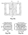
- FIG. 22 a depicts an embodiment of a mirror.
- FIG. 22 b depicts the complex amplitude trajectory of the mirror in FIG. 22 a.
- FIG. 22 c depicts a pixel transfer function of the mirror in FIG. 22 a.
- FIG. 22 d illustrates an array of pixel as illustrated in FIG. 22 a.
- FIG. 23 a depicts an embodiment of a mirror.
- FIG. 23 b depicts the complex amplitude trajectory of the mirror in FIG. 23 a.
- FIG. 23 c depicts a pixel transfer function of the mirror in FIG. 23 a.
- FIG. 24 a depicts an off grid filter implementation.
- FIG. 24 b depicts an off grid filter.
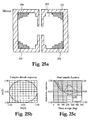
- FIG. 25 a depicts an embodiment of a mirror.
- FIG. 25 b depicts the complex amplitude trajectory of the mirror in FIG. 25 a.
- FIG. 25 c depicts a pixel transfer function of the mirror in FIG. 25 a.
- FIG. 26 a depicts an embodiment of a mirror.
- FIG. 26 b depicts the complex amplitude trajectory of the mirror in FIG. 26 a.
- FIG. 26 c depicts a pixel transfer function of the mirror in FIG. 26 a.
- FIG. 27 a depicts an embodiment of a mirror.
- FIG. 27 b depicts the complex amplitude trajectory of the mirror in FIG. 27 a.
- FIG. 27 c depicts a pixel transfer function of the mirror in FIG. 27 a.
- FIG. 28 a depicts an embodiment of a mirror.
- FIG. 28 b depicts the complex amplitude trajectory of the mirror in FIG. 28 a.
- FIG. 28 c depicts a pixel transfer function of the mirror in FIG. 28 a.
- FIG. 29 a depicts an embodiment of a mirror.
- FIG. 29 b depicts the complex amplitude trajectory of the mirror in FIG. 29 a.
- FIG. 29 c depicts a pixel transfer function of the mirror in FIG. 29 a.
- FIG. 30 a depicts an embodiment of a mirror.
- FIG. 30 b depicts the complex amplitude trajectory of the mirror in FIG. 30 a.
- FIG. 30 c depicts a pixel transfer function of the mirror in FIG. 30 a.
- FIG. 31 a depicts an embodiment of a mirror.
- FIG. 31 b depicts the complex amplitude trajectory of the mirror in FIG. 31 a.
- FIG. 31 c depicts a pixel transfer function of the mirror in FIG. 31 a.
- FIG. 32 a depicts a slanted line and its rasterized pixel representation
- FIG. 32 b depicts the exposure dose as a function of the position of said slanted line.
- FIG. 33 a illustrates the contrast as a function of spatial frequency for on-grid pixels and off-grid pixels without any grid filter.
- FIG. 33 b illustrates the contrast as a function of spatial frequency for on-grid pixels and off-grid pixels with an off-grid filter.
- FIG. 33 c illustrates the contrast as a function of spatial frequency for on-grid pixels and off-grid pixels with off-grid filter and global edge enhancement.
- FIG. 34 illustrates a diagram showing contrast as a function of pixel number.
- FIG. 35 a - b illustrate an embodiment of an off-grid correction filter according to the present invention.
- FIG. 36 illustrates resulting LUT functions for a gray and dark pixel.
- FIG. 37 a - 39 b illustrate calculated improvements due to the inventive off-grid filter.
- FIG. 40 a - b illustrate another embodiment of an off-grid correction filter according to the present invention.
- FIG. 41 a illustrates an SLM with amplitude transmission modulated pixels.
- FIG. 41 b illustrates an ideal pattern from a binary mask.
- FIG. 42 illustrates look up tables for pixels on and outside an edge.
- FIG. 43 illustrates performance comparison illumination table and grid filter (off-grid filter).
- FIG. 44 a illustrates an uncompensated edge in a pattern.
- FIG. 44 b illustrates a compensated edge in a pattern.
- FIG. 45 a illustrates an SLM with amplitude transmission modulated pixels.
- FIG. 45 b illustrates an ideal pattern from a binary mask.
- FIG. 46 illustrates look up tables for pixels on and outside an edge.
- Spatial light modulators come in two varieties, a deflection type and a phase type. The differences between them may in a particular case with micromirrors seem small but the phase SLM extinguishes the beam in a specular direction by destructive interference, while a pixel in a deflection SLM deflects the specular beam geometrically to one side so that it misses an aperture of an imaging lens.
- the deflection type SLM have pixels which operate digitally, i.e., said pixels may be set to two states only fully on and fully off. Said kind of pixels are said to be operated in a digital mode.
- the phase type SLM have pixels which operate in an analog mode, i.e., said pixels may be set to a numerous states between fully off and fully on.
- a degree of deflection of a micro-mirror determines which state said mirror would be in.
- All different states correspond to different gray-levels, which may be used to move edges of features to be printed.
- FIG. 1 depicts the general layout of an SLM pattern generator. Aspects of an SLM pattern generator are disclosed in the related-pending patent applications identified above.
- the workpiece to be exposed sits on a stage 112 .
- the position of the stage is controlled by precise positioning device, such as paired interferometers 113 .
- the workpiece may be a mask with a layer of resist or other exposure sensitive material or, for direct writing, it may be an integrated circuit with a layer of resist or other exposure sensitive material.
- the stage moves continuously.
- the stage In the other direction, generally perpendicular to the first direction, the stage either moves slowly or moves in steps, so that stripes of stamps are exposed on the workpiece.
- a flash command 108 is received at a pulsed excimer laser source 107 , which generates a laser pulse.
- This laser pulse may be in the deep ultraviolet (DUV) or extreme ultraviolet (EUV) spectrum range.
- the laser pulse is converted into an illuminating light 106 by a beam conditioner or homogenizer.
- a beam splitter 105 directs at least a portion of the illuminating light to an SLM 104 .
- the pulses are brief, such as only 20 ns long, so any stage movement is frozen during the flash.
- the SLM 104 is responsive to the datastream 101 , which is processed by a pattern rasterizer 102 .
- the SLM has 2048 ⁇ 512 mirrors that are 16 ⁇ 16 ⁇ m each and have a projected image of 80 ⁇ 80 nm. It includes a CMOS analog memory with a micro-mechanical mirror formed half a micron above each storage node.
- the electrostatic forces between the storage nodes and the mirrors actuate the mirrors.
- the device works in diffraction mode, not specular reflectance, and needs to deflect the mirrors by only a quarter of the wavelength (62 nm at 248 nm) to go from the fully on-state to the fully off-state.
- To create a fine address grid the mirrors are driven to on, off and 63 intermediate values.
- the pattern is stitched together from millions of images of the SLM chip. Flashing and stitching proceed at a rate of 1000 stamps per second. To eliminate stitching and other errors, the pattern is written four times with offset grids and fields. Furthermore, the fields may be blended along the edges.
- the mirrors are individually calibrated.
- a CCD camera sensitive to the excimer light, is placed in the optical path in a position equivalent to the image under the final lens.
- the SLM mirrors are driven through a sequence of known voltages and the response is measured by the camera.
- a calibration function is determined for each mirror, to be used for real-time correction of the grey-scale data during writing.
- the vector format pattern is rasterized into grey-scale images, with grey levels corresponding to dose levels on the individual pixels in the four writing passes. This image can then be processed using image processing.
- the final step is to convert the image to drive voltages for the SLM.
- the image processing functions are done in real time using programmable logic. Through various steps that have been disclosed in the related patent applications, rasterizer pattern data is converted into values 103 that are used to drive the SLM 104 .
- the SLM is a diffractive mode micromirror device.
- a variety of micromirror devices have been disclosed in the art.
- illuminating light could be directed through a micro-shutter device, such as in LCD array or a micromechanical shutter.
- An SLM pattern generator such as a mask writer or direct writer, that uses a grey-scale sampled image enables a variety of enhancement schemes.
- the grey value of each pixel is an area sample value of the pattern.
- adjustments of the exposure values in a predetermined vicinity of a corner feature can be used to mimic or match the properties of another pattern generator, such as the exposed corner radius and corner pull back.
- the adjustment recipe can be adapted to match, for instance, another mask writer. To do this, exposed pattern properties in resist on workpieces of the two pattern generators can be compared. The comparison can be based on either simulation, developed resist or latent images in resist. Comparison of the exposed patterns allows adjustment of one or more process control parameters until the exposed patterns essentially match.
- the process control parameters may relate to corner feature exposure properties.
- a mirror consisting of an essentially square mirror plate pivoting around an axis defined by torsion hinges in the plane of the mirror, see FIG. 2 , modulates the beam from fully-on to fully-off.
- the fully-off state depends on the illumination of the mirror.
- the illuminator defines an angular subtense, which in turn determines the lateral coherence of the illumination light.
- the lateral coherence is in this sense different from the temporal coherence.
- Temporal coherence usually means that the radiation comes from a laser, but lateral coherence can be produced by any light source made to illuminate a surface under a small enough angular spread. This is well known in the art and described in text books such as Born and Wolf: Principles of optics.
- the notion of lateral coherence length is significant to this discussion.
- the lateral coherence length is of the order of the typical or center wavelength of the radiation divided by the angular spread of the illuminating beam.
- Projectors known in prior art such as those used by Texas Instruments in their DLP technology and Daewoo in their AMA projectors have used a high angular spread leading to a coherence length smaller than the size of an individual mirror element, see FIG. 6 a . With this type of illumination each mirror acts as an independent specular reflector.
- the pattern generators disclosed and made by the applicant do on the other hand use a small angular spread in the illuminating beam, giving a coherence length that is of the same order as a mirror element or larger, see FIG.
- the effect is that different areas of a mirror interact by interference and that destructive or constructive interference effects also occur between mirror elements.
- the two different types of projectors will be called incoherent and partially coherent projectors respectively, the term projectors in this case meaning a generic image-forming system using an SLM, an illuminator and a projection system including a spatial filter.
- Incoherent projector are defined by the property of not forming a partially or fully coherent image, which can be due to the illumination mode, but also to a superposition of pixels at different times. The case where two or more fully coherent images are superimposed sequentially is considered as partially coherent.
- the mirror Under illumination where the lateral coherence extends over a full mirror, the mirror does not act as a simple analog light valve any more, but a complex amplitude modulator.
- the complex amplitude is related to the electric field of the radiation, while the intensity is more akin to the energy density or energy flow.
- An interesting property of the complex amplitude is that it can have a negative sign, see curve 320 in FIG. 3 , while the intensity (energy flow) is always positive, see FIG. 310 in FIG. 3 .
- With the illumination scheme that produces laterally coherent light it is possible for one light beamlet to cancel the light of another one. The consequence is that suitably conditioned radiation can be added to reduce the light intensity at a point were it is desired to be dark, thereby improving contrast.
- the square mirror 220 tilting along one of its axis 210 acts as a specular mirror when it is parallel to the plane of the surface. When it is successively tilted out of the plane the edges move out of phase and become more and more destructive, giving perfect extinction of the light when they have a phase shift of +/ ⁇ 180 degrees in reflection, see point 330 . But if the mirror is tilted more they continue further into the negative and the entire mirror gives negative complex amplitude. FIG. 3 shows this.
- the complex amplitude reflectivity of a mirror R can be calculated as the double integral over the mirror surface S 510 of the complex amplitude reflection r of every surface element Ds 520 .
- the denominator is the reflecting area of the mirror.
- the expression can be generalized to include differences between the surface elements.
- the complex amplitude reflectivity r of a surface element is
- r e ⁇ i(4 ⁇ h/ ⁇ ) , where h 530 is the height of the mirror surface 510 above a reference surface 540 .
- the reference surface 540 can be chosen arbitrarily (and the complex amplitude reflectivity R can be multiplied with an arbitrary but constant phase factor e i ⁇ ) with no change in the physics.
- FIG. 3 shows the reflected intensity and complex amplitude as functions of the tilt angle.
- the term ⁇ which is typically 10%, is introduced to allow even exposure even in the presence of some statistical variation in R from mirror to mirror.
- a fine address grid much finer than that given by the mirrors, is created by giving mirrors at the edge intermediate values. These values are interpolated between exposed and unexposed mirror tilts, times a non-linear function, the illumination table.
- the illumination table is implemented as a look-up table that is pre-computed or determined experimentally. The shape of the illumination function depends on a number of factors, most important on the projected mirror size compared to the optical resolution and the angular spread of the illuminating radiation.
- the complex quantity R does not have any meaning, since the surface integrals only have meaning for lateral coherence lengths on the scale of the mirror size.
- the quantity R is defined as a complex amplitude reflectivity in a partially coherent projector, not as the normal intensity reflectivity relevant in an incoherent projector.
- R is a complex number and may have any value as long as
- FIG. 4 depicts an example of a complex amplitude reflectivity curve 40 .
- One type of image enhancement is achieved by selecting the a value of R ⁇ 0 for areas that are intended to be unexposed.
- 2.25% is not enough to cause the photo resist (or more generally the photosensitive surface) to develop, since it has a development threshold typically around 30%.
- exposed features get crisper edges since the ⁇ 0.15 reflectivity, having phase 180 degrees, cancels light with phase 0 degrees at the perimeter of the exposed features. The dark areas get larger, the edge steeper and if the size is compensated with more dose the edge enhancement is even further enhanced.
- FIG. 7 a illustrates a prior art method of patterning features using an SLM.
- SLM pixels inside a feature to be patterned, hatched pixels in FIG. 7 a have a complex amplitude reflectivity R equal to 0.
- Pixels outside said feature, non-hatched pixels in FIG. 7 a have a complex amplitude reflectivity being equal to 1.
- the illustrated example in FIG. 7 a have feature edges coinciding with a pixel grid of the SLM. For this reason pixel elements defining the edge of the feature also have complex amplitude reflectivity equal to 0. If, however the feature edge falls between the pixel grid, said complex amplitude reflectivity will be any value in the range of 0 ⁇ R ⁇ 1. The value of R is depending on the placement of said edge.
- FIG. 7 a a graph 710 represents the complex amplitude of reflectivity R taken along a line A-A.
- FIG. 7 b illustrates the inventive method for creating features with increased edge acuity and placement accuracy.
- the pixels inside the feature, hatched pixels in FIG. 7 b have complex amplitude less than 0, i.e., a negative value.
- a graph 720 represents the complex amplitude reflectivity taken along line B-B. Inserted in FIG. 7 b is also the graph representing the intensity of reflectivity
- the use of negative R is analogous to the use of so-called attenuated or embedded phase shifting masks in lithography.
- the value of R to be selected at will between 0 and a minimum value. At first sight is seems that the minimum value is ⁇ 0.218. This corresponds to 4.77% exposure, less than 6% attenuated masks used in state-of-the-art lithography.
- a min A exposed * - 0.218 ( 1 - ⁇ )
- the value of the pixel of mirror at the feature edge has been calculated as an interpolation between the exposed and unexposed value based on how much of the pixel falls on the exposed feature. Before it is converted to drive signals for the SLM.
- Image modulator elements it is corrected through the illumination table LUT as described above.
- a digital filter (term taken in a wide sense) is applied to the rasterized data to enhance edges and corners.
- the filter can be designed and implemented in many ways: linear or non-linear, based on rules or mathematical operations.
- One of the simplest rules is that whenever a pixel has a neighbor that is gray (i.e. has an intermediate value) the current pixel is enhanced, so that a white pixel gets whiter (more positive) and a black pixel gets blacker (less positive).
- the range of pixel values is limited to zero to full illumination, in the partially coherent projector the pixel value has the range Amin ⁇ A ⁇ Amax where Amin can be negative.
- FIG. 8 a illustrates the way drive signals are converted before being fed to the SLM according to a first embodiment.
- Vector data is fractured and rasterized according to well-known principles in the art. Edge filters are applied according to methods described above and below.
- the illumination table and mirror look up table is used before the final drive signal is created.
- FIG. 8 b another embodiment is illustrated which uses two illumination tables instead of one. By doing so better CD control may be achieved.
- FIG. 8 c illustrates yet another embodiment which splits the rasterized data into two parallel branches.
- a first branch uses a first and second illumination table 1 a , 1 b , and a high pass filter.
- a second branch uses a third and a fourth illumination table and a low pass filter. Data split into high frequency and low frequency data.
- the digital image enhancements are comparatively easy to make in the bitmap domain.
- the pattern is typically input in a hierarchical vector format such as GDSII, MIC or OASIS.
- the ordering of data in the input file obeys no rules and a contiguous geometrical feature can be formed from several elements from different parts of the hierarchical structure.
- the hierarchy is flattened and all neighbor and overlap relations are resolved when the bitmap is created. Thus the bitmap operations need only look at local information, in contrast to operations in the vector format.
- FIG. 32 a illustrates a slanted line 325 and corresponding pixel data.
- a cut at A illustrates that said slanted line 325 lies on grid.
- FIG. 32 b illustrates exposure dose as function of position.
- FIG. 32 b illustrates that the graph is steeper for on grid position compared to off-grid positions.
- FIG. 33 a illustrates contrast versus spatial frequency for on-grid pixels and off-grid pixels without any grid filter.
- the upper sequence illustrates on-grid pixels and the lower sequence illustrates off-grid pixels.
- off-grid pixels i.e., a feature edge that does not fall on the grid position for SLM pixels, act as a low pass filter.
- the optics in a pattern generator also works as a low pass filter.
- the combination of the optics and the on grid gives an image with a certain low pass characteristic.
- the combination of off grid and the optics gives an image with another low pass characteristic (solid line) than what is expected, dotted line in FIG. 33 a.
- FIG. 33 b illustrates the contrast as a function of spatial frequency for on-grid pixels and off-grid pixels with an off-grid filter.
- the off-grid filter counteracts the low pass performance caused by the off grid position.
- the off grid image has equivalent contrast versus spatial frequency performance as the on grid image.
- FIG. 33 c illustrates the contrast as a function of spatial frequency for on-grid pixels and off-grid pixels with off-grid filter and global edge enhancement.
- the global filter enhances the contrast versus spatial frequency characteristics in that the graph is steeper in both the on-grid and off-grid image compared to the graph in the on-grid and off-grid image without said global filter (dotted graph). A steeper function will enhance edge placement accuracy and edge acuity.
- FIG. 34 illustrates a diagram showing contrast as a function of pixel number.
- Pixels 341 illustrates the area bitmap for a certain pattern.
- Pixels 343 illustrates said pixels with an off-grid filter applied.
- Pixels 345 illustrates convolved pixels, i.e., with a global edge enhancement.
- the global enhancement enhances all edges, while the off-grid filter enhances only edges with an intermediate value for the edge pixel.
- FIG. 10 a illustrates an alternating phase shift mask.
- the leftmost area is phase shifted 180 degrees relative to the rightmost area.
- the middle area is dark.
- a represenation of said alternating phase shift mask as complex amplitude reflectivity values is illustrated in FIG. 10 b .
- ⁇ 1 corresponds to the 180 degrees area
- +1 corresponds to the 0 degree area
- 0 corresponds to the dark area
- ⁇ 0.6 corresponds to the leftmost transition step
- 0.3 corresponds to the rightmost transition step.
- the remedy is what will be called an off-grid filter, a filter that detects that the edge is at an interpolated position and sharpens the edge by an appropriate amount to counteract the softening action of the rasterization.
- Edge sharpening by itself is well known in the image processing, although it is not common to have negative values available.
- One edge-sharpening operation is convolution with a partially derivative kernel. Such a kernel can look as follows:
- the derivative at the edge is increased by 40%.
- the following example shows how a corner is enhanced after convolution by the same kernel.
- B out ( ... ... ... ... ... ... ... ... 100 ⁇ ⁇ % 100 ⁇ ⁇ % 116 ⁇ ⁇ % 68 ⁇ ⁇ % - 24 ⁇ ⁇ % 0 ⁇ ⁇ % 0 ⁇ ⁇ % ... ... 100 ⁇ ⁇ % 100 ⁇ ⁇ % 116 ⁇ ⁇ % 68 ⁇ ⁇ % - 24 ⁇ ⁇ % 0 ⁇ ⁇ % 0 ⁇ ⁇ % ⁇ 100 ⁇ ⁇ % 100 ⁇ ⁇ % 116 ⁇ % 68 ⁇ % - 24 ⁇ ⁇ % 0 ⁇ ⁇ % ⁇ ⁇ 100 ⁇ ⁇ % 100 ⁇ ⁇ % 116 ⁇ % 68 ⁇ % - 24 ⁇ ⁇ % 0 ⁇ ⁇ % 0 ⁇ ⁇ % ⁇ 124 ⁇ ⁇ % 124 ⁇ ⁇ % 138
- a convolution with a derivative kernel enhances all edges, i.e. it does a global edge enhancement.
- the off-grid filter is rule-based in the sense that it enhances only off-grid edges.
- the off-grid filter detects that the edge is interpolated and enhances it, while an edge that is not interpolated is left unchanged.
- a simple condition for interpolation is that the edge pixels have an intermediate value.
- the rule that only interpolated edges are enhanced can be expressed as an IF-THEN-ELSE rule in the bitmap domain, but a more elegant implementation is by means of multiplication with a weight function that continuously varies between a small magnitude in an on-grid position and a high magnitude in an off-grid position.
- FIG. 24 a illustrates an off-grid filter implementation.
- B is the bitmap from the rasterizer with values in the range 0-1.
- K is a coefficient array or kernel 3 ⁇ 5, 5 ⁇ 5 pixels or larger.
- W is a weighting bitmap used to weight the contribution to each entry in the bitmap B.
- Wn 4*(1 ⁇ Bn)*Bn+max(4*(1 ⁇ Bneighbors)*Bneighbors).
- W 13 4*(1 ⁇ B 13)* B 13+MAX(4*(1 ⁇ B 7)* B 7, . . . , 4*(1 ⁇ B 12)* B 12,4*1 ⁇ B 14)* B 14, . . . , 4*(1 ⁇ B 19)* B 19).
- FIG. 24 b illustrates another off-grid filter.
- B is the bitmap from the rasterizer with values in the range 0-1.
- G and F are derived bitmaps used for the filter.
- Gn 2(Bn ⁇ 0.5).
- Fn 4(Bn ⁇ 1)(Bn ⁇ 0).
- K is a coefficient array or kernel 3 ⁇ 5, 5 ⁇ 5 pixels or larger.
- the constants used in the edge enhancement and for the calculation of the “grayness” can be varied to produce as good results as possible for a variety of typical pattern elements, “use cases”. They can be determined manually by controlled experiments or by simulations using codes such as PROLYTH from KLA-Tencor or Solid-C from Sigma-C. In a more elaborate setup the use cases can be programmed into an optimization job using one of the simulators above and non-linear optimization routines.
- FIGS. 35 a - b illustrate another embodiment of an off-grid correction filter.
- This version of the off-grid filter operates during rasterization on the area bitmap and detects and raises gray pixels and lowers dark pixel neighbours to negative black.
- the pixel values are changed with two look-up tables, pre-computed before exposure, one for the gray pixel and one for the dark pixel.
- FIG. 35 a to the left, illustrates an uncompensated edge including a grey pixel P 1 , a dark pixel P 2 and a light pixel.
- P 1 * LUT 1 (P 1 )
- the LUTs are calculated with an infinite edge moving over one pixel in n steps, for instance, using the MATLAB linspace function on an equivalent. For each nominal edge position (corresponding to an area coverage), the position and Image Log Slope at a reference level is compared with when edge is on grid. A reference level is determined for pattern on grid. The LUTs are calculated iteratively.
- LUT1(1: n, 1) linspace(0,1 ,n )
- LUT1(1 :n, 2) linspace(0,1 n )
- LUT2(1: n, 1) lispace(0,1 ,n )
- FIG. 36 illustrates resulting LUT functions.
- LUT 1 for P 1 is the top line in the graph.
- LUT 2 , for P 2 almost reaches down to maximum negative black amplitude attainable by a tilting micromirror.
- FIGS. 37 a - b , 38 a - b and 39 a - b Calculations of the improvement due to this embodiment of the off-grid filter are illustrated in FIGS. 37 a - b , 38 a - b and 39 a - b .
- Some of the parameters used to calculate these results were: 90 nm dense L/S; annular illumination 0.7/0.9; 2 nm mesh grid; 30 nm pixel size; 13 pupil mesh points; and NA 0.92925925925926.
- FIG. 37 a - b illustrates placement error versus grid shift.
- the smallest placement error of zero corresponds to a grid shift of 0, 15 or 30 nm, using an illumination table LUT.
- the off-grid correction filter of this embodiment there is very little placement error, regardless of the grid shift, through the range of 0 to 30 nm.
- the contrast attained between opposing sides of the intended boundary between dark and light is again graphed against grid shift for the illumination table LUT ( 38 a ) and the off-grid correction filter of this embodiment ( 38 b ).
- normalized image log slope is plotted against grid shift for the illumination table LUT ( 39 a ) and the off-grid correction filter of this embodiment ( 39 b ).
- Those of skill in the art will understand that normalized image log slope is normalized to feature size and tends to be proportional to exposure latitude. Varying the parameters to 60 nm dense L/S and 15 pupil mesh points changes the shapes of some of the curves in these figures, but generally confirms the performance of this embodiment of the off-grid filter.
- FIGS. 40 a - b Operation of another embodiment is illustrated in FIGS. 40 a - b .
- This version of the off-grid filter also operates directly on the area bitmap and replaces the illimunation table LUT.
- edges are detected, and the edge pixel and the two neighbouring pixels are modified.
- the pixel values are changed with three look-up tables, one for each pixel.
- the look-up tables are pre-computed before exposure.
- P 1 grey pixel
- P 2 dark pixel
- P 3 light pixel
- the LUTs are calculated by substantially minimizing the difference in the Fourier transform (FT) from the SLM and a perfect binary or phase-shifting mask over the projection optics pupil.
- FT Fourier transform
- the edge offset correction filter which may substantially minimize the difference in the Fourier transform from projecting radiation from the aligned pixels of the SLM and a perfect binary mask or phase shifting mask over the projection optics pupil may be performed using one two, three or more pixels.
- FIG. 41 a illustrates an SLM with a feature with a width w*(1+gl), were w is the pixel width and gl is in the range [0, 1].
- the pixels are modeled with an amplitude transmission that can have negative values.
- a, b, and c are parameters used to minimize the diffraction pattern difference compared to the ideal case.
- the complementary FIG. 41 b illustrates an ideal pattern from a binary mask.
- the feature has the same width as in the SLM case, w*(1+gl).
- FT_SLM(fx,a,b,c,gl) ⁇ FT_ideal(fx,gl) is for each value of gl, minimized for all fx in the range [ ⁇ NA(1+sigma)/lambda, NA(1+sigma)/lambda].
- NA is the numerical aperture of the projection optics and sigma is the degree of coherence in the illumination.
- FT_SLM w * sin ⁇ ⁇ c ⁇ ( w * fx ) * ( 1 + a + ( g ⁇ ⁇ 1 + b ) * exp ⁇ ( - i * 2 * p * w * fx ) + c * exp ⁇ ( - i * 4 * p * w * fx ) )
- FT_ideal w * sin ⁇ ⁇ c ⁇ ( w * fx ) + g ⁇ ⁇ 1 * w * sin ⁇ ⁇ c ⁇ ( g ⁇ ⁇ 1 * w * fx ) * exp ⁇ ( - i * p * w * fx ⁇ ( 1 + g ⁇ ⁇ 1 ) )
- FIGS. 44 and 45 illustrates in the same way as FIGS. 41 and 42 , an SLM and an ideal pattern from a reference reticle both with a feature with a width w*(1+gl), where w is the pixel width, gl is in the range [0,1], and gld is equal to gl*(1 ⁇ d)+d, i.e. gld is equal to gl scaled to the range [d, 1].
- the transmission in the area outside of the feature is not zero, but instead the amplitude has a magnitude d, which can have any value from ⁇ 1 up to any value lower than the transmission in the bright areas.
- d can be zero as in a binary mask, between ⁇ 1 and zero as in phase-shifting masks, or ⁇ 1 as in CPL.
- FT_SLM w * sin ⁇ ⁇ c ⁇ ( w * fx ) * ( 1 + a - d + ( g ⁇ ⁇ 1 ⁇ ⁇ d + b - d ) * exp ⁇ ( - i * 2 * p * w * fx ) + c * exp ⁇ ( - i * 4 * p * w * fx ) ) + d * ⁇ ⁇ ( fx )
- FT_ideal ( 1 - d ) * w * sin ⁇ ⁇ c ⁇ ( w * fx ) + ( 1 - d ) * w * sin ⁇ ⁇ c ⁇ ( g ⁇ ⁇ 1 * w * fx ) * exp ⁇ ( - i * p * w * fx ⁇ ( 1 + g ⁇ ⁇ 1 ) ) + d * ⁇ ⁇ ( fx )
- the equations above apply to binary, weak and strong phase-shifting (CPL).
- CPL binary, weak and strong phase-shifting
- AAPSM alternating aperture phase-shifting masks
- the equations above cannot be applied directly.
- AAPSM the bright areas in the mask with opposite phase must be treated separately and the resulting pixel values are added together.
- the areas with zero phase can simply, together with the surrounding dark areas, be treated as from a binary mask and the corresponding settings should be used.
- the bright areas with 180 degree phase can, together with the surrounding dark areas, in the same way be treated as from a binary mask, but simply with a negative transmission.
- the value of d corresponds to a 6% attenuated phase-shift mask.
- FIG. 9 a - d shows simulated performance of a manually fitted enhanced space (clear line).
- the vector data has one edge 912 on grid and one off grid 914 .
- the result is an aerial image where the on-grid edge has higher acuity than the off-grid one.
- the dose is varied the width of the trench varies, but the two edges 991 , 992 move differently with dose. This is seen as a movement of the center of the space with dose.
- the diagram 9 d shows the movement with dose of the center of the space without 970 and with 980 the off-grid filter. It is seen that with the off-grid edge enhanced the center of the space is stable over a very large dose interval. This is an alternative way to describe that the left and right edges in the aerial image are closely identical.
- a pixel within the feature 940 is set to a higher exposure value, here 116% compared to the rest of the pixels within the feature, which are set to 100%.
- a pixel 950 outside the feature is set to a negative black value, i.e., a negative complex amplitude reflectivity. The rest of the outside feature pixels are set to 0%.
- the operation can conceptually be expressed as a convolution with two parts.
- B out B in ⁇ circle around (x) ⁇ (D global +g*D off-grid ), where Dglobal is the edge enhancement kernel for global edge enhancement, Doff-grid the kernel for removing the difference between off-grid and on-grid edges and g is the “grayness”, the weight function that determines the application of Doff-grid.
- the convolution kernel or more generally the digital filter, has slightly different properties in the x and y directions to correct for inherent differences in edge acuity between x and y.
- the pixel values In order to print a true image of the input data the pixel values cannot be a linear representation of the overlap between the pixel area and the feature. There has to be a non-linear transformation between overlap area and pixel value. Regardless if the representation of the pixel values is chosen to be tilt angle, actuator voltage, complex amplitude reflectivity R or
- a non-linear pixel-by-pixel transformation is needed: V I(A)*A where V is the pixel value, A the area overlap from 0 to 100%, and I(A) is the illumination table.
- the illumination table I(A) describes the non-linearity of the system that arises from the partial coherence over the modulating element (mirror). The shape of the function depends on the pixel size relative to the optical resolution, the angular spread of the illuminating light, the used dynamic range of the SLM, and the relative dose (dose/dose-to-clear).
- the illumination function can be determined empirically or through optical simulation. In either case the printing conditions such as NA, illuminator setting, pixel size, SLM contrast, and dose are fixed.
- a large feature is printed from vector data with the placement of one edge versus the grid varying, either in resist or virtually in a lithography simulator.
- the pixel value is a predetermined function of the feature overlap with the pixel area, possibly with a non-uniform weight function over the pixel area
- the predetermined function can for example be a linear function.
- the feature is printed for different edge placements and the placement of the printed edge is measured, either by a metrology system such as Leica IPRO or by numerical analysis of the simulated images.
- the measurement gives a non-linear function for placement vs. data.
- This non-linear function is used to compute the illumination table.
- the procedure can be repeated iteratively in order to arrive at a stable and accurate illumination table.
- This illumination table makes the printer print true to data for large features with the used printing conditions.
- a preferred embodiment of the invention has the following order of conversions: see FIG. 8 a
- FIG. 8 b A slightly more complex conversion sequence gives more control of the non-linearities of the rasterizing and partially coherent imaging: see FIG. 8 b 1.
- Flatten the hierarchical input database 2. Rasterize all features and compute the overlap area of feature elements for every bitmap pixel (possibly using a non-uniform area sampling function per pixel) producing a so called area bitmap, 2b
- Multiply the area bitmap by a first illumination function 3.
- Make pattern corrections (preferably in real time) including edge enhancement and off-grid enhancement as well as special enhancement of corners and small features, producing a corrected area bitmap, 4.
- Multiply the corrected bitmap by a second illumination function producing what is currently called an intensity bitmap
- the pattern is divided into two (possibly three or more) partial patterns, e.g. one containing more high-frequency information and another one containing more low-frequency information.
- the partial patterns are converted with different parameters before they are combined to drive the SLM.
- the decomposition is suitably implemented as different bitmap filters such as the convolutions described above. High and low frequency filtering of images is well known in the art of digital image processing and many methods and detailed implementations can be devised by a person skilled in the art.
- the illumination function can be folded into the mirror look-up table.
- the mirror LUT Look Up Table
- the mirror LUT must then be changed depending on the angular spread of the illumination and the dose.
- the illumination table makes the CD independent of the pixel grid, at least for large features. But the illumination does not make the aerial image acuity constant through grid. Features at the resolution limit tend to disappear, and features placed at grid positions where the acuity is compromised by the rasterization disappear first. Therefore line width CD is not stable through grid at the resolution limit.
- the off-grid enhancement makes the image of on-gid and off grid identical. This makes all printing properties more stable, e.g. for varying dose. But the main benefit is that features at the resolution limit become much more stable. In this way the useful resolution is improved.
- the global edge enhancement also increases the useful resolution. It increases the contrast of thin lines by extending the dynamic range of the SLM modulator elements. Edges are made crisper. Since small features have the edges close together they get a double boost.
- the edge enhancement method is exemplified by embodiments based on tilting micromirror SLMs. It is obvious that the same methods can be applied to other SLMs or modulator arrays, in particular to SLMs having the ability to create negative complex amplitude, such as micromechanical mirrors having pistoning or combined pistoning and tilting action or LCD SLMs.
- Line ends are also improved, partly because all edges are made crisper, but also because the convolution with a derivating kernel enhances the contrast of line ends. Corners are likewise enhanced, although not as much as line ends. With properly chosen parameters line end shortening and CD linearity failures of lines and contacts can be largely counteracted. If the global enhancement is implemented as a convolution with a derivating kernel the size of the kernel and the coefficients in it can be used to determine the magnitude and detailed properties of the enhancement. The complex amplitude of the square mirror and how it varies with the tilt angle is calculated as described above. It is influenced by the shape of the mirror. Other shapes give other characteristics and shown in FIG. 14-23 , 25 - 31 .
- FIG. 10 a , 18 a , 19 a are surface filling.
- FIG. 14 a - 23 a , 25 a - 31 a shows that many perfectly viable mirror shapes have radically different complex amplitude reflectivity. By selecting a different mirror shape one can get access to large amounts of negative R.
- Some of the shapes like the H shape in FIG. 22 a , can provide a symmetrical positive and negative R.
- FIG. 11 a depicts mirror configurations in a spatial light modulator, which may be used in order to achieve any desired pattern with improved image quality.
- Mirror 1110 and 1120 have their tilting axis along symmetry line 1130 .
- Mirror 1110 have outer areas with phase 0 and inner area with phase 180 .
- Mirror 1120 are reversed relative to mirror 1110 , i.e., outer areas have phase 180 and inner area has phase 0 .
- Mirror 1110 and 1120 are arranged in a chess board manner, i.e., mirror 1110 is surrounded by four 1120 mirrors and mirror 1120 is surrounded by four 1110 mirrors.
- FIG. 11 b illustrates the real part of the complex amplitude reflectivity as function of a degree of tilting of the mirror.
- FIG. 11 b mirror element 1110 goes from +1 to ⁇ 1 as the mirror is tilted and mirror element 1120 goes from ⁇ 1 to +1 as the mirror is tilted.
- FIGS. 11 a and 11 b patterns as depicted in FIG. 12 a - 12 e can easily be achieved.
- FIG. 12 a illustrates a pattern with uniform phase 0 . Only mirrors 1120 , denoted in FIG. 12 a with phase 180 and an arrow, are tilted. The direction of said arrow indicates the direction of tilting. Every second mirror is tilted in a reversed direction. However mirrors may all be tilted in the same direction.
- FIG. 12 b illustrates a pattern with uniform phase 180 .
- FIG. 12 b are only the mirrors 1110 tilted, denoted in FIG. 12 b with phase 0 and an arrow.
- a direction of said arrow indicates the direction of tilting said mirror.
- FIG. 12 c - e depict patterns with uniform dark.
- none of the mirrors are tilted.
- all mirrors are tilted.
- all mirrors are partially tilted.
- the direction of said arrow indicates the tilting direction of the mirror.
- FIG. 12 shows a number of possible designs and corresponding properties.
- FIG. 13 a - d illustrates the correspondence between Masks or reticles and an SLM having similar properties.
- a leftmost illustration in FIG. 13 a depicts a binary mask.
- the binary mask has a part, which is covered with a chrome layer. Said chrome layer is opaque. Next to the chrome layer said mask is clear, defining a fully transmissive part of said mask.
- a rightmost illustration depicts an SLM with corresponding properties as said binary mask.
- a leftmost illustration in FIG. 13 b depicts an attenuating phase shift mask.
- the attenuating phase shift mask has a part, which is covered with a partly transmissive layer. Next to the partly transmissive layer said mask is clear, defining a fully transmissive part of said mask.
- a rightmost illustration depicts an SLM with corresponding properties as said attenuating phase shift mask.
- a leftmost illustration in FIG. 13 c depicts an alternating phase shift mask.
- the alternating phase shift mask has a first part, which is covered with a chrome layer. Said chrome layer is opaque. At one side of the chrome layer said mask is clear, defining a fully transmissive part of said mask. At another side of said chrome layer said mask is shifted in phase relative said chrome layer and said clear part.
- a rightmost illustration depicts an SLM with corresponding properties as said alternating phase shift mask.
- a leftmost illustration in FIG. 13 d depicts a CPL (Chrome-less Phase Lithography) mask.
- the CPL mask has a part, which is covered with a shifted layer. Said shifted layer is clear and fully transmissive. Next to the shifted layer said mask is clear, defining a fully transmissive part of said mask. The shifted part has its surface higher or lower than said clear part.
- the rightmost illustration depicts an SLM with corresponding properties as said CPL mask.
- the different parts in FIG. 13 a - d comprises typically a plurality of pixel elements, i.e., in the SLM case said areas are represented by a plurality of SLM pixels, the number depending on the size of the feature to be patterned.
- FIG. 14-31 illustrates different mirror configurations and corresponding complex amplitude trajectory, complex amplitude reflectivity graph and exposure graph as a function of phase at an edge of the mirror.
- FIG. 14 a illustrates a square shaped mirror 145 capable to be tilted at hinges 147 , 148 defining a tilting axis.
- FIG. 14 b illustrates the complex trajectory for said square shaped mirror. As can be seen from FIG. 14 b an imaginary part of the complex amplitude is almost zero indicating that the mirror element is nearly symmetrical. Symmetrical mirror elements have the imaginary part equal to zero.
- FIG. 14 c illustrates the reflection and exposure as functions of a phase of the mirror element at an edge of the same. The reflection is the real part of the complex amplitude reflectivity. The exposure is the square of the real part of the complex amplitude reflectivity. In the same FIG. 14 c a magnified portion of the exposure is illustrated. A square mirror has a relatively low level of negative real part of the complex amplitude, therefore full phase shifting cannot be obtained.
- FIG. 15 a illustrates another configuration of a mirror.
- the hinges 157 , 158 are attached to the mirror 155 closer to the center compared to the mirror in FIG. 14 a .
- This embodiment has less reflecting area compared to the mirror illustrated in FIG. 14 a , especially it has less reflecting area close to the tilting axis defined by the hinges 157 , 158 .
- This will affect the minimum value of the complex amplitude as illustrated in FIGS. 15 b and 15 c , in that the real part has a minimum, which is more negative than the embodiment illustrated in FIG. 14 a.
- FIG. 16 a illustrates another configuration of a mirror.
- the hinges 167 , 168 are attached to the mirror 165 even closer to the center compared to FIG. 14 a and FIG. 15 a .
- This embodiment has less reflecting area compared to the mirror illustrated in FIG. 14 a and 15 a , especially it has less reflecting area close to the tilting axis defined by the hinges 167 , 168 .
- This will affect the minimum value of the complex amplitude as illustrated in FIGS. 16 b and 16 c , in that the real part has a minimum, which is more negative than the embodiment illustrated in FIG. 14 a and FIG. 15 a.
- FIG. 17 a illustrates yet another configuration of a mirror.
- the hinges 177 , 178 are attached to two diagonally displaced corners of the mirror 175 .
- the illustrated embodiment has no negative complex amplitude, neither real nor imaginary.
- FIG. 18 a illustrates still another configuration of a mirror 185 .
- To said mirror 185 are attached two hinges 187 , 188 , defining a tilting axis.
- This configuration has two sides, which are zigzag-formed, where one is the inverse of the other.
- This configuration is perfectly suitable to be stitched together in a one- or two-dimensional array of micromirrors, such as in a spatial light modulator.
- the complex amplitude trajectory is illustrated in FIG. 18 b , which indicates that this embodiment has a slightly negative complex amplitude.
- FIG. 18 c illustrates the exposure and reflection for the configuration in FIG. 18 a.
- FIG. 19 a illustrates still another configuration of a mirror 195 .
- To said mirror 195 are attached two hinges 197 , 198 , defining a tilting axis.
- This embodiment has also two sides where one is the inverse of the other one.
- This configuration is suitable to be stitched together in the one or two-dimensional array of mirrors. As can be seen in FIGS. 19 b and 19 c this embodiment has less negative complex amplitude compared to the configuration illustrated in FIG. 18 a.
- FIG. 20 a illustrates still another configuration of a mirror 205 .
- This embodiment differs to the one illustrated in FIG. 19 a in that a reflecting area is slightly less than the embodiment illustrated in FIG. 19 a . Areas are cut off around an attachment position of hinges 207 , 208 , which is not the case in FIG. 19 a . As can be seen in FIG. 20 b , 20 c , this embodiment has slightly more negative complex amplitude than the configuration in FIG. 19 a.
- FIG. 21 a illustrates still another mirror configuration.
- hinges 217 , 218 define a tilting axis.
- the mirror area is much less close to the tilting axis compared to further away, which will affect the complex amplitude of the mirror, see FIG. 21 b and 21 c .
- the mirror element is almost symmetrical there is no imaginary part of the complex amplitude present.
- the real part of the complex amplitude is more negative than all previously illustrated embodiments above.
- FIG. 22 a illustrates still another mirror configuration.
- Hinges 227 and 228 define a tilting axis as previous. In this embodiment there is almost no reflecting area close to the tilting axis. Nearly all reflecting areas are at a distance from the tilting axis. This will increase the negative complex amplitude even more compared to the embodiment illustrated in FIG. 21 a .
- This configuration is also suitable to be arranged in a one or two-dimensional array of mirror elements. This is illustrated in FIG. 22 d.
- FIG. 23 illustrates still another mirror configuration 235 .
- Hinges are attached to support structures 237 , 238 .
- the hinge are may be covered with an anti-reflective coating in order not to reflect any radiation at a predetermined wavelength, said hinges are hidden for said reason n FIG. 23 a .
- Also hidden is a connecting element connecting reflecting areas 236 , 239 .
- This configuration exhibit exceptional complex amplitude values as indicated in FIG. 23 b and FIG. 23 c .
- the real part of the complex amplitude goes from +1 to ⁇ 1 and there is no imaginary part of the complex amplitude.
- FIG. 25 a illustrates still another embodiment of a mirror configuration 255 .
- This embodiment differs to the one illustrated in FIG. 15 a in that some corner areas 251 , 252 , 253 , 254 of the mirror are out of phase relative the rest of the mirror.
- Preferably said corner areas affect a reflected wavelength so that said reflected wavelength from said corner areas are 180 degrees out of phase relative to the other mirror areas.
- the complex amplitude will decrease compared to the embodiment in FIG. 15 a.
- FIG. 26 a illustrates still another mirror configuration 265 .
- this configuration there are two areas 261 , 262 which are out of phase relative to the rest of the mirror.
- Preferably said areas affect a reflected wavelength so that said reflected wavelength from said areas are 180 degrees out of phase relative to the other mirror areas.
- This embodiment will affect the complex amplitude, see FIG. 26 b , 26 c , slightly different compared to the embodiment illustrated in FIG. 25 a.
- FIG. 27 a illustrates yet another embodiment of a mirror configuration 275 .
- out of phase areas 271 , 272 larger than the out of phase areas in FIG. 26 a .
- This will affect the position of the local maximum and minimum positions of the reflection, see FIG. 27 c compared with FIG. 26 c , as well as this embodiment give a more negative complex amplitude than the embodiment in FIG. 26 a.
- FIG. 28 a illustrates still another mirror configuration 285 .
- the central part of the mirror is covered with an area 281 , which area is 180 degrees out of phase relative the rest of the mirror.
- This embodiment will cause the complex amplitude to go from +1 to ⁇ 1, see FIG. 28 b , 28 c.
- FIG. 29 a illustrates still another mirror configuration 295 .
- the central part of the mirror 295 is covered with an area 180 degrees out of phase relative the rest of the mirror.
- the area is slightly differently shaped compared to the one in FIG. 28 a , resulting in slightly different complex amplitude values, see FIG. 29 a , 29 b.
- FIG. 30 a illustrates still another mirror configuration 305 having a central part covered with an area 180 degrees out of phase relative to the rest of the mirror.
- the area 180 degrees out of phase relative to the other part of the mirror apply to reflected light/electromagnetic radiation.
- FIG. 31 a illustrates still another mirror configuration 315 .
- a first area 311 is ⁇ 90 degrees out of phase relative to the non-hatched mirror areas.
- a second area 312 is +90 degrees out of phase relative the non-hatched parts of the mirror.
- This embodiment will give an extended deflection range giving 0 reflection, see FIG. 31 c .
- this mirror configuration has no imaginary part.
- FIG. 31 a has areas (hatched in figure) with different heights than lambda over four. Such structures can be used to further modify the pixel characteristics.
- the first one relates to full phase shifting capability, which means that the complex amplitude reflectivity goes from +1 to ⁇ 1, a plurality of mirror configurations having such characteristic has been disclosed above.
- the second one relates to attenuated phase shift masks, which means that the complex amplitude goes from +1 to ⁇ 0,245.
- the third one relates to an ordinary chrome mask, which means that the complex amplitude goes from +1 to 0.
- a suitable mirror design gives a relative flat graph for the complex amplitude as a function of mirror tilt angle or reflected light at the edge of the mirror. Such mirror design will not be so sensitive to changes in tilt angle for the desired gray-value of the mirror element.
- the H shape is also surface filling, but gives a pattern that is not optimal for rasterizing.
- An equivalent mirror shape can be created from a square mirror place by reduction of the mirror reflectivity on some areas.
- the reflectivity can be reduced by coatings of a low-reflectance material or by structuring the surface to create destructive interference or light scattering away from the projection optics.
- the illumination with the small angular spread used makes it possible to use rather large surface structures.
- the SLM also has intermediate values not present in commonly used masks. These are used for placement of edges in a fine address grid. They can also be used for phase-shifting lithography equivalent to “high transmission PSMs” and “tri-tone masks” known in the art e.g. for printing of dense contacts.
- the shifter features are usually printed with an overlap of the chrome so that the chrome data determines the dimension in the mask.
- An embodiment of an SLM printer using phase-shifting SLMs follows the scheme above. It rasterizes two binary (two-valued) input files and combines them in a Boolean operation to create the multi-valued SLM bitmap data. Each binary set of data can have its own set of bitmap operations, such as CD bias and edge enhancement. This preserves the highest degree of transparency between mask and maskless pattern data files.
- the rasterizer reads a file containing at least two types of areas and a background, e.g. clear and shifted areas in a dark background and rasterizes them directly to a multivalued bitmap.
- a background e.g. clear and shifted areas in a dark background
- rasterizes them directly to a multivalued bitmap This has the advantage of creating immediately interpolated edges for all types of feature boundaries: clear to dark, shifted to dark, and clear to shifted. It is also more suitable for working directly from the design database without the intermediate step of mask data tape-out.
- the relative benefits of the first and second type of rasterization depend on the application and a preferred embodiment can use either scheme.
Abstract
Description
Bout=Bin{circle around (x)}D
B13filtered=B13+W13*(K7*B7+ . . . +K19*B19), where W13=4*(1−B13)*B13+MAX(4*(1−B7)*B7, . . . , 4*(1−B12)*B12,4*1−B14)*B14, . . . , 4*(1−B19)*B19).
B13filtered=B13+K7*G7*F7*B7+ . . . +K19*G19*F19*B19.
LUT1(1:n,1)=linspace(0,1,n)
LUT1(1:n,2)=linspace(0,1n)
LUT2(1:n,1)=lispace(0,1,n)
LUT2(1:n,2)=a*x^2−a*x, x=linspace(0,1,n),
-
- where a=0.217*4, i.e maximum negative
black * 4, or something else
- where a=0.217*4, i.e maximum negative
P1*=LUT1(P1,2)
P2*=LUT2(P1,2)
Corr_pos=nominal_position/real_position
Corr_ILS=ILS_reference/ILS_real
LUT1_new(P1,2)=LUT1(P1,2)*Corr_pos
LUT2_new(P1,2)=LUT2(P1,2)*Corr_ILS
P1*=LUT1(P1)
P2*=LUT2(P1)
P3*=LUT2(P1)
-
- where LUT1, LUT2, and LUT3 are three different look-up tables.
-
- The equation system above can be re-written in a matrix form, A*x=h. The over-determined linear equation system A(fx)* [a, b, c]=h(fx,gl), is solved in a least square sense.
where δ(fx) is the dirac delta function.
Claims (18)
Priority Applications (1)
| Application Number | Priority Date | Filing Date | Title |
|---|---|---|---|
| US10/557,099 US7755657B2 (en) | 2003-06-12 | 2004-06-14 | Method for high precision printing of patterns |
Applications Claiming Priority (5)
| Application Number | Priority Date | Filing Date | Title |
|---|---|---|---|
| US10/460765 | 2003-06-12 | ||
| US10/460,765 US6833854B1 (en) | 2003-06-12 | 2003-06-12 | Method for high precision printing of patterns |
| US52436903P | 2003-11-20 | 2003-11-20 | |
| PCT/SE2004/000936 WO2004111701A1 (en) | 2003-06-12 | 2004-06-14 | Method for high precision printing of patterns |
| US10/557,099 US7755657B2 (en) | 2003-06-12 | 2004-06-14 | Method for high precision printing of patterns |
Publications (2)
| Publication Number | Publication Date |
|---|---|
| US20070165098A1 US20070165098A1 (en) | 2007-07-19 |
| US7755657B2 true US7755657B2 (en) | 2010-07-13 |
Family
ID=33555113
Family Applications (1)
| Application Number | Title | Priority Date | Filing Date |
|---|---|---|---|
| US10/557,099 Active 2026-11-03 US7755657B2 (en) | 2003-06-12 | 2004-06-14 | Method for high precision printing of patterns |
Country Status (5)
| Country | Link |
|---|---|
| US (1) | US7755657B2 (en) |
| EP (1) | EP1631853A1 (en) |
| JP (1) | JP2006527418A (en) |
| KR (1) | KR101098070B1 (en) |
| WO (1) | WO2004111701A1 (en) |
Cited By (5)
| Publication number | Priority date | Publication date | Assignee | Title |
|---|---|---|---|---|
| US20070285638A1 (en) * | 2006-06-07 | 2007-12-13 | Asml Netherlands B.V. | Mirror array for lithography |
| US20080219562A1 (en) * | 2004-04-30 | 2008-09-11 | Asml Holding N.V. | System and Method for Calculating Aerial Image of a Spatial Light Modulator |
| US8510687B1 (en) * | 2012-03-01 | 2013-08-13 | Taiwan Semiconductor Manufacturing Company, Ltd. | Error diffusion and grid shift in lithography |
| US20180166003A1 (en) * | 2017-09-29 | 2018-06-14 | Shanghai Tianma AM-OLED Co., Ltd. | Image processing method, apparatus, and display device |
| US11858217B2 (en) | 2020-09-17 | 2024-01-02 | Concept Laser Gmbh | Methods of determining an interlace path for an additive manufacturing machine |
Families Citing this family (19)
| Publication number | Priority date | Publication date | Assignee | Title |
|---|---|---|---|---|
| EP1482373A1 (en) | 2003-05-30 | 2004-12-01 | ASML Netherlands B.V. | Lithographic apparatus and device manufacturing method |
| US7643192B2 (en) * | 2004-11-24 | 2010-01-05 | Asml Holding N.V. | Pattern generator using a dual phase step element and method of using same |
| KR20070104444A (en) * | 2005-01-28 | 2007-10-25 | 에이에스엠엘 홀딩 엔.브이. | Method and system for a maskless lithography rasterization technique based on global optimization |
| US7499146B2 (en) * | 2005-03-14 | 2009-03-03 | Asml Netherlands B.V. | Lithographic apparatus and device manufacturing method, an integrated circuit, a flat panel display, and a method of compensating for cupping |
| US7403265B2 (en) * | 2005-03-30 | 2008-07-22 | Asml Netherlands B.V. | Lithographic apparatus and device manufacturing method utilizing data filtering |
| US20070153249A1 (en) * | 2005-12-20 | 2007-07-05 | Asml Netherlands B.V. | Lithographic apparatus and device manufacturing method using multiple exposures and multiple exposure types |
| EP2014137B1 (en) | 2006-05-04 | 2017-08-09 | LG Display Co., Ltd. | Organic light-emitting device having light-emitting pattern and method for preparing the same |
| US7738077B2 (en) * | 2006-07-31 | 2010-06-15 | Asml Netherlands B.V. | Patterning device utilizing sets of stepped mirrors and method of using same |
| US8049865B2 (en) | 2006-09-18 | 2011-11-01 | Asml Netherlands B.V. | Lithographic system, device manufacturing method, and mask optimization method |
| JP2011049296A (en) * | 2009-08-26 | 2011-03-10 | Nikon Corp | Maskless exposure method |
| NL2007918A (en) * | 2010-12-20 | 2012-06-21 | Asml Netherlands Bv | Method of controlling a patterning device in a lithographic apparatus, device manufacturing method and lithographic apparatus. |
| JP5953657B2 (en) * | 2011-05-17 | 2016-07-20 | 株式会社ニコン | Spatial light modulator, exposure apparatus, and device manufacturing method |
| CN104170054B (en) * | 2012-01-18 | 2018-11-02 | 株式会社尼康 | The driving method of spatial light modulator, the generation method of exposure pattern and exposure method and device |
| JP6113990B2 (en) * | 2012-10-01 | 2017-04-12 | 株式会社クラレ | Manufacturing method of fine structure |
| JP6593623B2 (en) * | 2015-03-30 | 2019-10-23 | 株式会社ニコン | Spatial light modulator setting method, drive data creation method, exposure apparatus, exposure method, and device manufacturing method |
| CN108803011A (en) * | 2018-03-15 | 2018-11-13 | 成都理想境界科技有限公司 | A kind of image correction method and optical fiber scanning imaging device |
| US10571809B1 (en) | 2019-02-19 | 2020-02-25 | Applied Materials, Inc. | Half tone scheme for maskless lithography |
| US10495979B1 (en) | 2019-02-19 | 2019-12-03 | Applied Materials, Inc. | Half tone scheme for maskless lithography |
| CN111816344B (en) * | 2020-07-01 | 2022-10-25 | 浙江大学 | Device for simultaneously manipulating low-refractive-index particles in multiple Rayleigh regions and achieving high capture efficiency |
Citations (17)
| Publication number | Priority date | Publication date | Assignee | Title |
|---|---|---|---|---|
| JPH03160877A (en) | 1989-11-20 | 1991-07-10 | Canon Inc | Picture reader |
| US5148157A (en) | 1990-09-28 | 1992-09-15 | Texas Instruments Incorporated | Spatial light modulator with full complex light modulation capability |
| US5467146A (en) | 1994-03-31 | 1995-11-14 | Texas Instruments Incorporated | Illumination control unit for display system with spatial light modulator |
| US5774254A (en) | 1997-06-26 | 1998-06-30 | Xerox Corporation | Fault tolerant light modulator display system |
| US5835256A (en) | 1995-06-19 | 1998-11-10 | Reflectivity, Inc. | Reflective spatial light modulator with encapsulated micro-mechanical elements |
| WO1999045441A1 (en) | 1998-03-02 | 1999-09-10 | Micronic Laser Systems Ab | Improved modulator design for pattern generator |
| US6088102A (en) | 1997-10-31 | 2000-07-11 | Silicon Light Machines | Display apparatus including grating light-valve array and interferometric optical system |
| US6142641A (en) | 1998-06-18 | 2000-11-07 | Ultratech Stepper, Inc. | Four-mirror extreme ultraviolet (EUV) lithography projection system |
| JP2000347642A (en) | 1999-06-07 | 2000-12-15 | Seiko Epson Corp | Device and method for image display, and device and method for image processing |
| WO2001018606A1 (en) | 1999-09-09 | 2001-03-15 | Micronic Laser Systems Ab | Data path for high performance pattern generator |
| JP2001228050A (en) | 2000-02-15 | 2001-08-24 | Seiko Epson Corp | Apparatus and method for detection of point defect |
| US20010040670A1 (en) | 1994-08-04 | 2001-11-15 | Fielding Raymond G. | Display system |
| US6348907B1 (en) | 1989-08-22 | 2002-02-19 | Lawson A. Wood | Display apparatus with digital micromirror device |
| US20020024714A1 (en) | 1998-03-02 | 2002-02-28 | Torbjorn Sandstrom | Pattern generator |
| US7328425B2 (en) * | 1999-05-20 | 2008-02-05 | Micronic Laser Systems Ab | Method and device for correcting SLM stamp image imperfections |
| US7405414B2 (en) * | 2001-12-14 | 2008-07-29 | Micronic Laser Systems Ab | Method and apparatus for patterning a workpiece |
| US7618751B2 (en) * | 2004-02-25 | 2009-11-17 | Micronic Laser Systems Ab | RET for optical maskless lithography |
-
2004
- 2004-06-14 US US10/557,099 patent/US7755657B2/en active Active
- 2004-06-14 EP EP04748994A patent/EP1631853A1/en not_active Withdrawn
- 2004-06-14 WO PCT/SE2004/000936 patent/WO2004111701A1/en active Application Filing
- 2004-06-14 KR KR1020057023861A patent/KR101098070B1/en not_active IP Right Cessation
- 2004-06-14 JP JP2006517032A patent/JP2006527418A/en active Pending
Patent Citations (20)
| Publication number | Priority date | Publication date | Assignee | Title |
|---|---|---|---|---|
| US6348907B1 (en) | 1989-08-22 | 2002-02-19 | Lawson A. Wood | Display apparatus with digital micromirror device |
| JPH03160877A (en) | 1989-11-20 | 1991-07-10 | Canon Inc | Picture reader |
| US5148157A (en) | 1990-09-28 | 1992-09-15 | Texas Instruments Incorporated | Spatial light modulator with full complex light modulation capability |
| US5467146A (en) | 1994-03-31 | 1995-11-14 | Texas Instruments Incorporated | Illumination control unit for display system with spatial light modulator |
| US20010040670A1 (en) | 1994-08-04 | 2001-11-15 | Fielding Raymond G. | Display system |
| US5835256A (en) | 1995-06-19 | 1998-11-10 | Reflectivity, Inc. | Reflective spatial light modulator with encapsulated micro-mechanical elements |
| US5774254A (en) | 1997-06-26 | 1998-06-30 | Xerox Corporation | Fault tolerant light modulator display system |
| US6088102A (en) | 1997-10-31 | 2000-07-11 | Silicon Light Machines | Display apparatus including grating light-valve array and interferometric optical system |
| US6504644B1 (en) | 1998-03-02 | 2003-01-07 | Micronic Laser Systems Ab | Modulator design for pattern generator |
| US6285488B1 (en) | 1998-03-02 | 2001-09-04 | Micronic Laser Systems Ab | Pattern generator for avoiding stitching errors |
| US20020024714A1 (en) | 1998-03-02 | 2002-02-28 | Torbjorn Sandstrom | Pattern generator |
| WO1999045441A1 (en) | 1998-03-02 | 1999-09-10 | Micronic Laser Systems Ab | Improved modulator design for pattern generator |
| US6142641A (en) | 1998-06-18 | 2000-11-07 | Ultratech Stepper, Inc. | Four-mirror extreme ultraviolet (EUV) lithography projection system |
| US7328425B2 (en) * | 1999-05-20 | 2008-02-05 | Micronic Laser Systems Ab | Method and device for correcting SLM stamp image imperfections |
| JP2000347642A (en) | 1999-06-07 | 2000-12-15 | Seiko Epson Corp | Device and method for image display, and device and method for image processing |
| WO2001018606A1 (en) | 1999-09-09 | 2001-03-15 | Micronic Laser Systems Ab | Data path for high performance pattern generator |
| US6717097B1 (en) | 1999-09-09 | 2004-04-06 | Micronic Laser Systems Ab | Data path for high performance pattern generator |
| JP2001228050A (en) | 2000-02-15 | 2001-08-24 | Seiko Epson Corp | Apparatus and method for detection of point defect |
| US7405414B2 (en) * | 2001-12-14 | 2008-07-29 | Micronic Laser Systems Ab | Method and apparatus for patterning a workpiece |
| US7618751B2 (en) * | 2004-02-25 | 2009-11-17 | Micronic Laser Systems Ab | RET for optical maskless lithography |
Non-Patent Citations (2)
| Title |
|---|
| Office Action for related copending EP Application No. 04748994.3-2217, dated Mar. 25, 2008. |
| Translation of Office Action for copending JP Application No. 2006-517032, dated Jan. 15, 2010. |
Cited By (8)
| Publication number | Priority date | Publication date | Assignee | Title |
|---|---|---|---|---|
| US20080219562A1 (en) * | 2004-04-30 | 2008-09-11 | Asml Holding N.V. | System and Method for Calculating Aerial Image of a Spatial Light Modulator |
| US7889411B2 (en) * | 2004-04-30 | 2011-02-15 | Asml Holding N.V. | System and method for calculating aerial image of a spatial light modulator |
| US20070285638A1 (en) * | 2006-06-07 | 2007-12-13 | Asml Netherlands B.V. | Mirror array for lithography |
| US8052289B2 (en) | 2006-06-07 | 2011-11-08 | Asml Netherlands B.V. | Mirror array for lithography |
| US8510687B1 (en) * | 2012-03-01 | 2013-08-13 | Taiwan Semiconductor Manufacturing Company, Ltd. | Error diffusion and grid shift in lithography |
| US20180166003A1 (en) * | 2017-09-29 | 2018-06-14 | Shanghai Tianma AM-OLED Co., Ltd. | Image processing method, apparatus, and display device |
| US10504400B2 (en) * | 2017-09-29 | 2019-12-10 | Shanghai Tianma AM-OLED Co., Ltd. | Method and apparatus for performing correction processing on grayscale of a pixel in an image |
| US11858217B2 (en) | 2020-09-17 | 2024-01-02 | Concept Laser Gmbh | Methods of determining an interlace path for an additive manufacturing machine |
Also Published As
| Publication number | Publication date |
|---|---|
| WO2004111701A1 (en) | 2004-12-23 |
| US20070165098A1 (en) | 2007-07-19 |
| JP2006527418A (en) | 2006-11-30 |
| EP1631853A1 (en) | 2006-03-08 |
| KR101098070B1 (en) | 2011-12-26 |
| KR20060017868A (en) | 2006-02-27 |
Similar Documents
| Publication | Publication Date | Title |
|---|---|---|
| US6833854B1 (en) | Method for high precision printing of patterns | |
| US7755657B2 (en) | Method for high precision printing of patterns | |
| EP1546788B1 (en) | Methods and systems for improved boundary contrast | |
| US7618751B2 (en) | RET for optical maskless lithography | |
| TWI291074B (en) | Optical proximity correction | |
| EP1449033B1 (en) | Defective pixel compensation method | |
| KR100734597B1 (en) | Lithographic apparatus, method, and computer program product for generating a mask pattern and device manufacturing method using same | |
| US20060068334A1 (en) | Phase-shifting optical maskless lithography enabling asics at the 65 and 45 NM nodes | |
| Lin | Phase-shifting and other challenges in optical mask technology | |
| JP4777968B2 (en) | Lithography system, device manufacturing method, setpoint data optimization method, and optimum setpoint data generation apparatus | |
| KR100770672B1 (en) | Method and system for maskless lithography real-time pattern rasterization and using computationally coupled mirrors to achieve optimum feature representation | |
| US20030233630A1 (en) | Methods and systems for process control of corner feature embellishment | |
| KR20020070130A (en) | An Optical Proximity Correction Method Utilizing Gray Bars As Sub-Resolution Assist Features | |
| US7372547B2 (en) | Process and apparatus for achieving single exposure pattern transfer using maskless optical direct write lithography | |
| Sandstrom et al. | RET for optical maskless lithography | |
| KR100864391B1 (en) | Methods for exposing patterns and emulating masks in optical maskless lithography | |
| Martinsson et al. | Rasterizing for SLM-based mask making and maskless lithography | |
| Martinsson et al. | Gray scaling in high performance mask making | |
| Martinsson et al. | Gray scaling in high performance optical pattern generators | |
| JP2009527911A (en) | SLM lithography: printing to less than K1 = 0.03 without previous OPC process |
Legal Events
| Date | Code | Title | Description |
|---|---|---|---|
| AS | Assignment |
Owner name: MICRONIC LASER SYSTEMS AB, SWEDEN Free format text: ASSIGNMENT OF ASSIGNORS INTEREST;ASSIGNORS:SANDSTROM, TORBJORN;MARTINSSON, HANS;REEL/FRAME:018669/0675;SIGNING DATES FROM 20061208 TO 20061211 Owner name: MICRONIC LASER SYSTEMS AB, SWEDEN Free format text: ASSIGNMENT OF ASSIGNORS INTEREST;ASSIGNORS:SANDSTROM, TORBJORN;MARTINSSON, HANS;SIGNING DATES FROM 20061208 TO 20061211;REEL/FRAME:018669/0675 |
|
| STCF | Information on status: patent grant |
Free format text: PATENTED CASE |
|
| FPAY | Fee payment |
Year of fee payment: 4 |
|
| MAFP | Maintenance fee payment |
Free format text: PAYMENT OF MAINTENANCE FEE, 8TH YEAR, LARGE ENTITY (ORIGINAL EVENT CODE: M1552) Year of fee payment: 8 |
|
| MAFP | Maintenance fee payment |
Free format text: PAYMENT OF MAINTENANCE FEE, 12TH YEAR, LARGE ENTITY (ORIGINAL EVENT CODE: M1553); ENTITY STATUS OF PATENT OWNER: LARGE ENTITY Year of fee payment: 12 |