US7745829B2 - Semiconductor device and fabrication method thereof - Google Patents

Semiconductor device and fabrication method thereof Download PDF

Info

Publication number
US7745829B2
US7745829B2 US12/230,954 US23095408A US7745829B2 US 7745829 B2 US7745829 B2 US 7745829B2 US 23095408 A US23095408 A US 23095408A US 7745829 B2 US7745829 B2 US 7745829B2
Authority
US
United States
Prior art keywords
film
over
tft
region
display device
Prior art date
Legal status (The legal status is an assumption and is not a legal conclusion. Google has not performed a legal analysis and makes no representation as to the accuracy of the status listed.)
Expired - Fee Related
Application number
US12/230,954
Other versions
US20090014724A1 (en
Inventor
Shunpei Yamazaki
Satoshi Murakami
Jun Koyama
Yukio Tanaka
Hidehito Kitakado
Hideto Ohnuma
Current Assignee (The listed assignees may be inaccurate. Google has not performed a legal analysis and makes no representation or warranty as to the accuracy of the list.)
Semiconductor Energy Laboratory Co Ltd
Original Assignee
Semiconductor Energy Laboratory Co Ltd
Priority date (The priority date is an assumption and is not a legal conclusion. Google has not performed a legal analysis and makes no representation as to the accuracy of the date listed.)
Filing date
Publication date
Application filed by Semiconductor Energy Laboratory Co Ltd filed Critical Semiconductor Energy Laboratory Co Ltd
Priority to US12/230,954 priority Critical patent/US7745829B2/en
Publication of US20090014724A1 publication Critical patent/US20090014724A1/en
Priority to US12/824,747 priority patent/US8030659B2/en
Application granted granted Critical
Publication of US7745829B2 publication Critical patent/US7745829B2/en
Priority to US13/238,754 priority patent/US8471262B2/en
Priority to US13/609,915 priority patent/US8558241B2/en
Priority to US13/609,906 priority patent/US8575619B2/en
Priority to US14/070,976 priority patent/US9431431B2/en
Priority to US15/248,469 priority patent/US9910334B2/en
Anticipated expiration legal-status Critical
Expired - Fee Related legal-status Critical Current

Links

Images

Classifications

    • GPHYSICS
    • G02OPTICS
    • G02FOPTICAL DEVICES OR ARRANGEMENTS FOR THE CONTROL OF LIGHT BY MODIFICATION OF THE OPTICAL PROPERTIES OF THE MEDIA OF THE ELEMENTS INVOLVED THEREIN; NON-LINEAR OPTICS; FREQUENCY-CHANGING OF LIGHT; OPTICAL LOGIC ELEMENTS; OPTICAL ANALOGUE/DIGITAL CONVERTERS
    • G02F1/00Devices or arrangements for the control of the intensity, colour, phase, polarisation or direction of light arriving from an independent light source, e.g. switching, gating or modulating; Non-linear optics
    • G02F1/01Devices or arrangements for the control of the intensity, colour, phase, polarisation or direction of light arriving from an independent light source, e.g. switching, gating or modulating; Non-linear optics for the control of the intensity, phase, polarisation or colour 
    • G02F1/13Devices or arrangements for the control of the intensity, colour, phase, polarisation or direction of light arriving from an independent light source, e.g. switching, gating or modulating; Non-linear optics for the control of the intensity, phase, polarisation or colour  based on liquid crystals, e.g. single liquid crystal display cells
    • G02F1/133Constructional arrangements; Operation of liquid crystal cells; Circuit arrangements
    • G02F1/136Liquid crystal cells structurally associated with a semi-conducting layer or substrate, e.g. cells forming part of an integrated circuit
    • G02F1/1362Active matrix addressed cells
    • G02F1/1368Active matrix addressed cells in which the switching element is a three-electrode device
    • GPHYSICS
    • G02OPTICS
    • G02FOPTICAL DEVICES OR ARRANGEMENTS FOR THE CONTROL OF LIGHT BY MODIFICATION OF THE OPTICAL PROPERTIES OF THE MEDIA OF THE ELEMENTS INVOLVED THEREIN; NON-LINEAR OPTICS; FREQUENCY-CHANGING OF LIGHT; OPTICAL LOGIC ELEMENTS; OPTICAL ANALOGUE/DIGITAL CONVERTERS
    • G02F1/00Devices or arrangements for the control of the intensity, colour, phase, polarisation or direction of light arriving from an independent light source, e.g. switching, gating or modulating; Non-linear optics
    • G02F1/01Devices or arrangements for the control of the intensity, colour, phase, polarisation or direction of light arriving from an independent light source, e.g. switching, gating or modulating; Non-linear optics for the control of the intensity, phase, polarisation or colour 
    • G02F1/13Devices or arrangements for the control of the intensity, colour, phase, polarisation or direction of light arriving from an independent light source, e.g. switching, gating or modulating; Non-linear optics for the control of the intensity, phase, polarisation or colour  based on liquid crystals, e.g. single liquid crystal display cells
    • G02F1/133Constructional arrangements; Operation of liquid crystal cells; Circuit arrangements
    • G02F1/1333Constructional arrangements; Manufacturing methods
    • G02F1/133345Insulating layers
    • GPHYSICS
    • G02OPTICS
    • G02FOPTICAL DEVICES OR ARRANGEMENTS FOR THE CONTROL OF LIGHT BY MODIFICATION OF THE OPTICAL PROPERTIES OF THE MEDIA OF THE ELEMENTS INVOLVED THEREIN; NON-LINEAR OPTICS; FREQUENCY-CHANGING OF LIGHT; OPTICAL LOGIC ELEMENTS; OPTICAL ANALOGUE/DIGITAL CONVERTERS
    • G02F1/00Devices or arrangements for the control of the intensity, colour, phase, polarisation or direction of light arriving from an independent light source, e.g. switching, gating or modulating; Non-linear optics
    • G02F1/01Devices or arrangements for the control of the intensity, colour, phase, polarisation or direction of light arriving from an independent light source, e.g. switching, gating or modulating; Non-linear optics for the control of the intensity, phase, polarisation or colour 
    • G02F1/13Devices or arrangements for the control of the intensity, colour, phase, polarisation or direction of light arriving from an independent light source, e.g. switching, gating or modulating; Non-linear optics for the control of the intensity, phase, polarisation or colour  based on liquid crystals, e.g. single liquid crystal display cells
    • G02F1/133Constructional arrangements; Operation of liquid crystal cells; Circuit arrangements
    • G02F1/1333Constructional arrangements; Manufacturing methods
    • G02F1/1345Conductors connecting electrodes to cell terminals
    • G02F1/13454Drivers integrated on the active matrix substrate
    • GPHYSICS
    • G02OPTICS
    • G02FOPTICAL DEVICES OR ARRANGEMENTS FOR THE CONTROL OF LIGHT BY MODIFICATION OF THE OPTICAL PROPERTIES OF THE MEDIA OF THE ELEMENTS INVOLVED THEREIN; NON-LINEAR OPTICS; FREQUENCY-CHANGING OF LIGHT; OPTICAL LOGIC ELEMENTS; OPTICAL ANALOGUE/DIGITAL CONVERTERS
    • G02F1/00Devices or arrangements for the control of the intensity, colour, phase, polarisation or direction of light arriving from an independent light source, e.g. switching, gating or modulating; Non-linear optics
    • G02F1/01Devices or arrangements for the control of the intensity, colour, phase, polarisation or direction of light arriving from an independent light source, e.g. switching, gating or modulating; Non-linear optics for the control of the intensity, phase, polarisation or colour 
    • G02F1/13Devices or arrangements for the control of the intensity, colour, phase, polarisation or direction of light arriving from an independent light source, e.g. switching, gating or modulating; Non-linear optics for the control of the intensity, phase, polarisation or colour  based on liquid crystals, e.g. single liquid crystal display cells
    • G02F1/133Constructional arrangements; Operation of liquid crystal cells; Circuit arrangements
    • G02F1/136Liquid crystal cells structurally associated with a semi-conducting layer or substrate, e.g. cells forming part of an integrated circuit
    • G02F1/1362Active matrix addressed cells
    • G02F1/136227Through-hole connection of the pixel electrode to the active element through an insulation layer
    • GPHYSICS
    • G02OPTICS
    • G02FOPTICAL DEVICES OR ARRANGEMENTS FOR THE CONTROL OF LIGHT BY MODIFICATION OF THE OPTICAL PROPERTIES OF THE MEDIA OF THE ELEMENTS INVOLVED THEREIN; NON-LINEAR OPTICS; FREQUENCY-CHANGING OF LIGHT; OPTICAL LOGIC ELEMENTS; OPTICAL ANALOGUE/DIGITAL CONVERTERS
    • G02F1/00Devices or arrangements for the control of the intensity, colour, phase, polarisation or direction of light arriving from an independent light source, e.g. switching, gating or modulating; Non-linear optics
    • G02F1/01Devices or arrangements for the control of the intensity, colour, phase, polarisation or direction of light arriving from an independent light source, e.g. switching, gating or modulating; Non-linear optics for the control of the intensity, phase, polarisation or colour 
    • G02F1/13Devices or arrangements for the control of the intensity, colour, phase, polarisation or direction of light arriving from an independent light source, e.g. switching, gating or modulating; Non-linear optics for the control of the intensity, phase, polarisation or colour  based on liquid crystals, e.g. single liquid crystal display cells
    • G02F1/133Constructional arrangements; Operation of liquid crystal cells; Circuit arrangements
    • G02F1/136Liquid crystal cells structurally associated with a semi-conducting layer or substrate, e.g. cells forming part of an integrated circuit
    • G02F1/1362Active matrix addressed cells
    • G02F1/136286Wiring, e.g. gate line, drain line
    • HELECTRICITY
    • H01ELECTRIC ELEMENTS
    • H01LSEMICONDUCTOR DEVICES NOT COVERED BY CLASS H10
    • H01L27/00Devices consisting of a plurality of semiconductor or other solid-state components formed in or on a common substrate
    • H01L27/02Devices consisting of a plurality of semiconductor or other solid-state components formed in or on a common substrate including semiconductor components specially adapted for rectifying, oscillating, amplifying or switching and having at least one potential-jump barrier or surface barrier; including integrated passive circuit elements with at least one potential-jump barrier or surface barrier
    • H01L27/12Devices consisting of a plurality of semiconductor or other solid-state components formed in or on a common substrate including semiconductor components specially adapted for rectifying, oscillating, amplifying or switching and having at least one potential-jump barrier or surface barrier; including integrated passive circuit elements with at least one potential-jump barrier or surface barrier the substrate being other than a semiconductor body, e.g. an insulating body
    • H01L27/1214Devices consisting of a plurality of semiconductor or other solid-state components formed in or on a common substrate including semiconductor components specially adapted for rectifying, oscillating, amplifying or switching and having at least one potential-jump barrier or surface barrier; including integrated passive circuit elements with at least one potential-jump barrier or surface barrier the substrate being other than a semiconductor body, e.g. an insulating body comprising a plurality of TFTs formed on a non-semiconducting substrate, e.g. driving circuits for AMLCDs
    • H01L27/1222Devices consisting of a plurality of semiconductor or other solid-state components formed in or on a common substrate including semiconductor components specially adapted for rectifying, oscillating, amplifying or switching and having at least one potential-jump barrier or surface barrier; including integrated passive circuit elements with at least one potential-jump barrier or surface barrier the substrate being other than a semiconductor body, e.g. an insulating body comprising a plurality of TFTs formed on a non-semiconducting substrate, e.g. driving circuits for AMLCDs with a particular composition, shape or crystalline structure of the active layer
    • HELECTRICITY
    • H01ELECTRIC ELEMENTS
    • H01LSEMICONDUCTOR DEVICES NOT COVERED BY CLASS H10
    • H01L27/00Devices consisting of a plurality of semiconductor or other solid-state components formed in or on a common substrate
    • H01L27/02Devices consisting of a plurality of semiconductor or other solid-state components formed in or on a common substrate including semiconductor components specially adapted for rectifying, oscillating, amplifying or switching and having at least one potential-jump barrier or surface barrier; including integrated passive circuit elements with at least one potential-jump barrier or surface barrier
    • H01L27/12Devices consisting of a plurality of semiconductor or other solid-state components formed in or on a common substrate including semiconductor components specially adapted for rectifying, oscillating, amplifying or switching and having at least one potential-jump barrier or surface barrier; including integrated passive circuit elements with at least one potential-jump barrier or surface barrier the substrate being other than a semiconductor body, e.g. an insulating body
    • H01L27/1214Devices consisting of a plurality of semiconductor or other solid-state components formed in or on a common substrate including semiconductor components specially adapted for rectifying, oscillating, amplifying or switching and having at least one potential-jump barrier or surface barrier; including integrated passive circuit elements with at least one potential-jump barrier or surface barrier the substrate being other than a semiconductor body, e.g. an insulating body comprising a plurality of TFTs formed on a non-semiconducting substrate, e.g. driving circuits for AMLCDs
    • H01L27/124Devices consisting of a plurality of semiconductor or other solid-state components formed in or on a common substrate including semiconductor components specially adapted for rectifying, oscillating, amplifying or switching and having at least one potential-jump barrier or surface barrier; including integrated passive circuit elements with at least one potential-jump barrier or surface barrier the substrate being other than a semiconductor body, e.g. an insulating body comprising a plurality of TFTs formed on a non-semiconducting substrate, e.g. driving circuits for AMLCDs with a particular composition, shape or layout of the wiring layers specially adapted to the circuit arrangement, e.g. scanning lines in LCD pixel circuits
    • HELECTRICITY
    • H01ELECTRIC ELEMENTS
    • H01LSEMICONDUCTOR DEVICES NOT COVERED BY CLASS H10
    • H01L27/00Devices consisting of a plurality of semiconductor or other solid-state components formed in or on a common substrate
    • H01L27/02Devices consisting of a plurality of semiconductor or other solid-state components formed in or on a common substrate including semiconductor components specially adapted for rectifying, oscillating, amplifying or switching and having at least one potential-jump barrier or surface barrier; including integrated passive circuit elements with at least one potential-jump barrier or surface barrier
    • H01L27/12Devices consisting of a plurality of semiconductor or other solid-state components formed in or on a common substrate including semiconductor components specially adapted for rectifying, oscillating, amplifying or switching and having at least one potential-jump barrier or surface barrier; including integrated passive circuit elements with at least one potential-jump barrier or surface barrier the substrate being other than a semiconductor body, e.g. an insulating body
    • H01L27/1214Devices consisting of a plurality of semiconductor or other solid-state components formed in or on a common substrate including semiconductor components specially adapted for rectifying, oscillating, amplifying or switching and having at least one potential-jump barrier or surface barrier; including integrated passive circuit elements with at least one potential-jump barrier or surface barrier the substrate being other than a semiconductor body, e.g. an insulating body comprising a plurality of TFTs formed on a non-semiconducting substrate, e.g. driving circuits for AMLCDs
    • H01L27/1248Devices consisting of a plurality of semiconductor or other solid-state components formed in or on a common substrate including semiconductor components specially adapted for rectifying, oscillating, amplifying or switching and having at least one potential-jump barrier or surface barrier; including integrated passive circuit elements with at least one potential-jump barrier or surface barrier the substrate being other than a semiconductor body, e.g. an insulating body comprising a plurality of TFTs formed on a non-semiconducting substrate, e.g. driving circuits for AMLCDs with a particular composition or shape of the interlayer dielectric specially adapted to the circuit arrangement
    • HELECTRICITY
    • H01ELECTRIC ELEMENTS
    • H01LSEMICONDUCTOR DEVICES NOT COVERED BY CLASS H10
    • H01L27/00Devices consisting of a plurality of semiconductor or other solid-state components formed in or on a common substrate
    • H01L27/02Devices consisting of a plurality of semiconductor or other solid-state components formed in or on a common substrate including semiconductor components specially adapted for rectifying, oscillating, amplifying or switching and having at least one potential-jump barrier or surface barrier; including integrated passive circuit elements with at least one potential-jump barrier or surface barrier
    • H01L27/12Devices consisting of a plurality of semiconductor or other solid-state components formed in or on a common substrate including semiconductor components specially adapted for rectifying, oscillating, amplifying or switching and having at least one potential-jump barrier or surface barrier; including integrated passive circuit elements with at least one potential-jump barrier or surface barrier the substrate being other than a semiconductor body, e.g. an insulating body
    • H01L27/1214Devices consisting of a plurality of semiconductor or other solid-state components formed in or on a common substrate including semiconductor components specially adapted for rectifying, oscillating, amplifying or switching and having at least one potential-jump barrier or surface barrier; including integrated passive circuit elements with at least one potential-jump barrier or surface barrier the substrate being other than a semiconductor body, e.g. an insulating body comprising a plurality of TFTs formed on a non-semiconducting substrate, e.g. driving circuits for AMLCDs
    • H01L27/1259Multistep manufacturing methods
    • HELECTRICITY
    • H01ELECTRIC ELEMENTS
    • H01LSEMICONDUCTOR DEVICES NOT COVERED BY CLASS H10
    • H01L29/00Semiconductor devices adapted for rectifying, amplifying, oscillating or switching, or capacitors or resistors with at least one potential-jump barrier or surface barrier, e.g. PN junction depletion layer or carrier concentration layer; Details of semiconductor bodies or of electrodes thereof  ; Multistep manufacturing processes therefor
    • H01L29/40Electrodes ; Multistep manufacturing processes therefor
    • H01L29/43Electrodes ; Multistep manufacturing processes therefor characterised by the materials of which they are formed
    • H01L29/45Ohmic electrodes
    • H01L29/456Ohmic electrodes on silicon
    • H01L29/458Ohmic electrodes on silicon for thin film silicon, e.g. source or drain electrode
    • HELECTRICITY
    • H01ELECTRIC ELEMENTS
    • H01LSEMICONDUCTOR DEVICES NOT COVERED BY CLASS H10
    • H01L29/00Semiconductor devices adapted for rectifying, amplifying, oscillating or switching, or capacitors or resistors with at least one potential-jump barrier or surface barrier, e.g. PN junction depletion layer or carrier concentration layer; Details of semiconductor bodies or of electrodes thereof  ; Multistep manufacturing processes therefor
    • H01L29/66Types of semiconductor device ; Multistep manufacturing processes therefor
    • H01L29/68Types of semiconductor device ; Multistep manufacturing processes therefor controllable by only the electric current supplied, or only the electric potential applied, to an electrode which does not carry the current to be rectified, amplified or switched
    • H01L29/76Unipolar devices, e.g. field effect transistors
    • H01L29/772Field effect transistors
    • H01L29/78Field effect transistors with field effect produced by an insulated gate
    • H01L29/786Thin film transistors, i.e. transistors with a channel being at least partly a thin film
    • H01L29/78606Thin film transistors, i.e. transistors with a channel being at least partly a thin film with supplementary region or layer in the thin film or in the insulated bulk substrate supporting it for controlling or increasing the safety of the device
    • H01L29/78618Thin film transistors, i.e. transistors with a channel being at least partly a thin film with supplementary region or layer in the thin film or in the insulated bulk substrate supporting it for controlling or increasing the safety of the device characterised by the drain or the source properties, e.g. the doping structure, the composition, the sectional shape or the contact structure
    • H01L29/78621Thin film transistors, i.e. transistors with a channel being at least partly a thin film with supplementary region or layer in the thin film or in the insulated bulk substrate supporting it for controlling or increasing the safety of the device characterised by the drain or the source properties, e.g. the doping structure, the composition, the sectional shape or the contact structure with LDD structure or an extension or an offset region or characterised by the doping profile
    • H01L29/78627Thin film transistors, i.e. transistors with a channel being at least partly a thin film with supplementary region or layer in the thin film or in the insulated bulk substrate supporting it for controlling or increasing the safety of the device characterised by the drain or the source properties, e.g. the doping structure, the composition, the sectional shape or the contact structure with LDD structure or an extension or an offset region or characterised by the doping profile with a significant overlap between the lightly doped drain and the gate electrode, e.g. GOLDD
    • HELECTRICITY
    • H01ELECTRIC ELEMENTS
    • H01LSEMICONDUCTOR DEVICES NOT COVERED BY CLASS H10
    • H01L29/00Semiconductor devices adapted for rectifying, amplifying, oscillating or switching, or capacitors or resistors with at least one potential-jump barrier or surface barrier, e.g. PN junction depletion layer or carrier concentration layer; Details of semiconductor bodies or of electrodes thereof  ; Multistep manufacturing processes therefor
    • H01L29/66Types of semiconductor device ; Multistep manufacturing processes therefor
    • H01L29/68Types of semiconductor device ; Multistep manufacturing processes therefor controllable by only the electric current supplied, or only the electric potential applied, to an electrode which does not carry the current to be rectified, amplified or switched
    • H01L29/76Unipolar devices, e.g. field effect transistors
    • H01L29/772Field effect transistors
    • H01L29/78Field effect transistors with field effect produced by an insulated gate
    • H01L29/786Thin film transistors, i.e. transistors with a channel being at least partly a thin film
    • H01L29/78651Silicon transistors
    • H01L29/7866Non-monocrystalline silicon transistors
    • H01L29/78672Polycrystalline or microcrystalline silicon transistor
    • H01L29/78675Polycrystalline or microcrystalline silicon transistor with normal-type structure, e.g. with top gate
    • HELECTRICITY
    • H10SEMICONDUCTOR DEVICES; ELECTRIC SOLID-STATE DEVICES NOT OTHERWISE PROVIDED FOR
    • H10KORGANIC ELECTRIC SOLID-STATE DEVICES
    • H10K59/00Integrated devices, or assemblies of multiple devices, comprising at least one organic light-emitting element covered by group H10K50/00
    • H10K59/10OLED displays
    • H10K59/12Active-matrix OLED [AMOLED] displays
    • H10K59/121Active-matrix OLED [AMOLED] displays characterised by the geometry or disposition of pixel elements
    • H10K59/1213Active-matrix OLED [AMOLED] displays characterised by the geometry or disposition of pixel elements the pixel elements being TFTs
    • HELECTRICITY
    • H10SEMICONDUCTOR DEVICES; ELECTRIC SOLID-STATE DEVICES NOT OTHERWISE PROVIDED FOR
    • H10KORGANIC ELECTRIC SOLID-STATE DEVICES
    • H10K59/00Integrated devices, or assemblies of multiple devices, comprising at least one organic light-emitting element covered by group H10K50/00
    • H10K59/10OLED displays
    • H10K59/12Active-matrix OLED [AMOLED] displays
    • H10K59/123Connection of the pixel electrodes to the thin film transistors [TFT]
    • HELECTRICITY
    • H10SEMICONDUCTOR DEVICES; ELECTRIC SOLID-STATE DEVICES NOT OTHERWISE PROVIDED FOR
    • H10KORGANIC ELECTRIC SOLID-STATE DEVICES
    • H10K59/00Integrated devices, or assemblies of multiple devices, comprising at least one organic light-emitting element covered by group H10K50/00
    • H10K59/10OLED displays
    • H10K59/12Active-matrix OLED [AMOLED] displays
    • H10K59/124Insulating layers formed between TFT elements and OLED elements
    • HELECTRICITY
    • H10SEMICONDUCTOR DEVICES; ELECTRIC SOLID-STATE DEVICES NOT OTHERWISE PROVIDED FOR
    • H10KORGANIC ELECTRIC SOLID-STATE DEVICES
    • H10K59/00Integrated devices, or assemblies of multiple devices, comprising at least one organic light-emitting element covered by group H10K50/00
    • H10K59/10OLED displays
    • H10K59/12Active-matrix OLED [AMOLED] displays
    • H10K59/126Shielding, e.g. light-blocking means over the TFTs
    • HELECTRICITY
    • H10SEMICONDUCTOR DEVICES; ELECTRIC SOLID-STATE DEVICES NOT OTHERWISE PROVIDED FOR
    • H10KORGANIC ELECTRIC SOLID-STATE DEVICES
    • H10K59/00Integrated devices, or assemblies of multiple devices, comprising at least one organic light-emitting element covered by group H10K50/00
    • H10K59/10OLED displays
    • H10K59/12Active-matrix OLED [AMOLED] displays
    • H10K59/131Interconnections, e.g. wiring lines or terminals
    • GPHYSICS
    • G02OPTICS
    • G02FOPTICAL DEVICES OR ARRANGEMENTS FOR THE CONTROL OF LIGHT BY MODIFICATION OF THE OPTICAL PROPERTIES OF THE MEDIA OF THE ELEMENTS INVOLVED THEREIN; NON-LINEAR OPTICS; FREQUENCY-CHANGING OF LIGHT; OPTICAL LOGIC ELEMENTS; OPTICAL ANALOGUE/DIGITAL CONVERTERS
    • G02F2201/00Constructional arrangements not provided for in groups G02F1/00 - G02F7/00
    • G02F2201/12Constructional arrangements not provided for in groups G02F1/00 - G02F7/00 electrode
    • G02F2201/123Constructional arrangements not provided for in groups G02F1/00 - G02F7/00 electrode pixel
    • GPHYSICS
    • G02OPTICS
    • G02FOPTICAL DEVICES OR ARRANGEMENTS FOR THE CONTROL OF LIGHT BY MODIFICATION OF THE OPTICAL PROPERTIES OF THE MEDIA OF THE ELEMENTS INVOLVED THEREIN; NON-LINEAR OPTICS; FREQUENCY-CHANGING OF LIGHT; OPTICAL LOGIC ELEMENTS; OPTICAL ANALOGUE/DIGITAL CONVERTERS
    • G02F2202/00Materials and properties
    • G02F2202/10Materials and properties semiconductor
    • G02F2202/104Materials and properties semiconductor poly-Si
    • HELECTRICITY
    • H01ELECTRIC ELEMENTS
    • H01LSEMICONDUCTOR DEVICES NOT COVERED BY CLASS H10
    • H01L29/00Semiconductor devices adapted for rectifying, amplifying, oscillating or switching, or capacitors or resistors with at least one potential-jump barrier or surface barrier, e.g. PN junction depletion layer or carrier concentration layer; Details of semiconductor bodies or of electrodes thereof  ; Multistep manufacturing processes therefor
    • H01L29/66Types of semiconductor device ; Multistep manufacturing processes therefor
    • H01L29/68Types of semiconductor device ; Multistep manufacturing processes therefor controllable by only the electric current supplied, or only the electric potential applied, to an electrode which does not carry the current to be rectified, amplified or switched
    • H01L29/76Unipolar devices, e.g. field effect transistors
    • H01L29/772Field effect transistors
    • H01L29/78Field effect transistors with field effect produced by an insulated gate
    • H01L29/786Thin film transistors, i.e. transistors with a channel being at least partly a thin film
    • H01L29/78606Thin film transistors, i.e. transistors with a channel being at least partly a thin film with supplementary region or layer in the thin film or in the insulated bulk substrate supporting it for controlling or increasing the safety of the device
    • H01L29/78618Thin film transistors, i.e. transistors with a channel being at least partly a thin film with supplementary region or layer in the thin film or in the insulated bulk substrate supporting it for controlling or increasing the safety of the device characterised by the drain or the source properties, e.g. the doping structure, the composition, the sectional shape or the contact structure
    • H01L29/78621Thin film transistors, i.e. transistors with a channel being at least partly a thin film with supplementary region or layer in the thin film or in the insulated bulk substrate supporting it for controlling or increasing the safety of the device characterised by the drain or the source properties, e.g. the doping structure, the composition, the sectional shape or the contact structure with LDD structure or an extension or an offset region or characterised by the doping profile
    • H01L2029/7863Thin film transistors, i.e. transistors with a channel being at least partly a thin film with supplementary region or layer in the thin film or in the insulated bulk substrate supporting it for controlling or increasing the safety of the device characterised by the drain or the source properties, e.g. the doping structure, the composition, the sectional shape or the contact structure with LDD structure or an extension or an offset region or characterised by the doping profile with an LDD consisting of more than one lightly doped zone or having a non-homogeneous dopant distribution, e.g. graded LDD
    • HELECTRICITY
    • H10SEMICONDUCTOR DEVICES; ELECTRIC SOLID-STATE DEVICES NOT OTHERWISE PROVIDED FOR
    • H10KORGANIC ELECTRIC SOLID-STATE DEVICES
    • H10K59/00Integrated devices, or assemblies of multiple devices, comprising at least one organic light-emitting element covered by group H10K50/00
    • H10K59/10OLED displays
    • H10K59/12Active-matrix OLED [AMOLED] displays
    • H10K59/1201Manufacture or treatment

Definitions

  • This invention relates to a semiconductor device having a circuit comprising thin film transistors (hereinafter referred to as “TFTs”) on a substrate having an insulation surface, and to a fabrication method of such a semiconductor device. More specifically, the present invention relates to electro-optical apparatuses (called also “electronic appliances”) typified by a liquid crystal display device including a pixel unit (pixel matrix circuit) and driving circuits (driver circuits) disposed around the pixel unit and formed on the same substrate and an EL (Electro-Luminescence) display device, and electrical appliances (called also “electronic appliances”) having the electro-optical apparatus mounted thereto.
  • electro-optical apparatuses typified by a liquid crystal display device including a pixel unit (pixel matrix circuit) and driving circuits (driver circuits) disposed around the pixel unit and formed on the same substrate and an EL (Electro-Luminescence) display device, and electrical appliances (called also “electronic appliances”) having the electro-optical apparatus mounted thereto
  • semiconductor device used in this specification represents generally those apparatuses which function by utilizing semiconductor characteristics, and includes also the electro-optical apparatuses and electrical appliances using the electro-optical apparatus described above.
  • TFTs formed on a substrate having an insulation surface
  • An active matrix type liquid crystal display device, an EL display device and a close adhesion type image sensor are typical of such semiconductor devices.
  • TFTs using a polycrystalline silicon film (typically, a poly-Si film) as an active layer have high field mobility, they can form a variety of functional circuits.
  • an integrated circuit that includes a pixel unit for displaying images for each functional block, a shift register circuit, a level shifter circuit, a buffer circuit, a sampling circuit, and so forth, each being based on a CMOS circuit, is formed on one substrate.
  • an integrated circuit such as a sample-and-hold circuit, a shift register circuit, a multiplexer circuit, and so forth, is formed by using the TFTs.
  • the pixel unit comprises a pixel TFT functioning as a switching device and an auxiliary holding capacitance, and a voltage is applied to a liquid crystal to drive it.
  • an alternating current must be applied to drive the liquid crystal, and a system called “frame inversion driving” has gained a wide application. Therefore, one of the required characteristics of the TFT is that an OFF current value (a drain current value flowing through the TFT when it is in the OFF operation) must be sufficiently lowered.
  • the TFT Because a high driving voltage is applied to the buffer circuit, the TFT must have a high withstand voltage such that it does not undergo breakdown even when a high voltage is applied. In order to improve the current driving capacity, it is necessary to sufficiently secure the ON current value (the drain current value flowing through the TFT when it is in the ON operation).
  • the poly-silicon TFT involves the problem that its OFF current is likely to become high. Degradation such as the drop of the ON current value is observed in the poly-silicon TFT in the same way as in MOS transistors used for ICs, or the like. It is believed that the main cause is hot carrier injection, and the hot carriers generated by a high field in the proximity of the drain presumably invite this degradation.
  • LDD Lightly Doped Drain
  • This structure forms an impurity region having a low concentration between a channel formation region and a source or drain region to which an impurity is doped in a high concentration.
  • the low concentration impurity region is called the “LDD region”.
  • GOLD Gate-drain Overlapped LDD structures
  • LDD Drain Overlapped LDD
  • the LDD region is so arranged as to overlap with a gate wiring through a gate insulation film in this structure, this structure is effective for preventing hot carrier injection in the proximity of the drain and for improving reliability.
  • Mutsuko Hatano, Hajime Akimoto and Takeshi Sakai, “IEDM97 Technical Digest”, pp. 523-526, 1997 discloses a GOLD structure using side walls formed from silicon. It has been confirmed that this structure provides by far higher reliability than the TFTs having other structures.
  • a TFT is disposed for each of dozens to millions of pixels and a pixel electrode is disposed for each TFT.
  • An opposing electrode is provided on an opposing substrate side sandwiching a liquid crystal, and forms a kind of capacitors using the liquid crystal as a dielectric.
  • the voltage to be applied to each pixel is controlled by the switching function of the TFT.
  • the liquid crystal is driven, and an image is displayed by controlling the quantity of transmitting rays of light.
  • the required characteristics of the pixel TFT of the pixel unit are not always the same as the required characteristics of the TFT (hereinafter called the “driving TFT”) of a logic circuit (called also the “driving circuit”) such as the shift register circuit and the buffer circuit.
  • the driving TFT a large reverse bias voltage (a negative voltage in n-channel TFT) is applied to the gate wiring in the pixel TFT, but the TFT of the driving circuit is not fundamentally driven by the application of the reverse bias voltage.
  • the operation speed of the former may be lower than 1/100 of the latter.
  • the GOLD structure has a high effect for preventing the degradation of the ON current value, it is true, but is not free from the problem that the OFF current value becomes greater than the ordinary LDD structures. Therefore, the GOLD structure cannot be said as an entirely preferable structure for the pixel TFT, in particular. On the contrary, the ordinary LDD structures have a high effect for restricting the OFF current value, but is not resistant to hot carrier injection, as is well known in the art.
  • an aperture ratio (a ratio of an area capable of image display to an area of one pixel) must be sacrificed.
  • the area per pixel is so small that the drop of the aperture ratio by the capacitance wiring becomes a serious problem.
  • the present invention aims at improving operation performance and reliability of a semiconductor device by optimizing the structures of the TFT used for each circuit of the semiconductor device in accordance with the function of each circuit.
  • the present invention employs the following constructions.
  • a semiconductor device including a pixel unit and a driving circuit on the same substrate the present invention provides a semiconductor device wherein an LDD region of an n-channel TFT forming the driving circuit described above is formed in such a fashion that a part or the whole part thereof overlaps with a gate wiring of the n-channel TFT while sandwiching a gate insulation film between them, and an LDD region of a pixel TFT that forms the pixel unit is formed in such a fashion as not to overlap with a gate wiring of the pixel TFT while sandwiching a gate insulation film.
  • the holding capacitance of the pixel unit may comprise a shading film arranged on a resin film, an oxide of the shading film and a pixel electrode. According to this arrangement, the holding capacitance can be formed with an extremely small area and consequently, the aperture ratio of the pixel can be improved.
  • this driving circuit includes a first n-channel TFT formed in such a fashion that the whole part of its LDD region overlaps with a gate wiring while sandwiching a gate insulation film between them, and a second n-channel TFT formed in such a fashion that a part of its LDD region overlaps with a gate wiring while sandwiching a gate insulation film between them, and the pixel unit includes a pixel TFT formed in such a fashion that an LDD region does not overlap with a gate wiring while sandwiching a gate insulation film between them.
  • a holding capacitance of the pixel unit may comprise a shading film disposed on an organic resin film, an oxide of the shading film and a pixel electrode.
  • the LDD region of the n-channel TFT forming the driving circuit may contain an element belonging to the Group 15 of the Periodic Table in a concentration higher by 2 to 10 times that of the LDD region of the pixel TFT.
  • the LDD region of the first n-channel TFT may be formed between a channel formation region and a drain region, and the LDD regions of the second n-channel TFT may be so formed as to sandwich the channel formation region between them.
  • the present invention employs the following construction.
  • the method according to the present invention comprises the steps of forming a channel formation region, a source region, a drain region and an LDD region between the drain region and the channel formation region, in an active layer of a first n-channel TFT that forms the driving circuit; forming a channel formation region, a source region, a drain region, an LDD region between the source region and the channel formation region and an LDD region between the drain region and the channel formation region, in an active layer of a second n-channel TFT that forms the driving circuit; forming a channel formation region, a source region and a drain region in an active layer of a p-channel TFT that forms the driving circuit; and forming a channel formation region, a source region, a drain region and an LDD region between the drain region and the channel formation region, in an active layer of a first n-channel TFT that forms the driving circuit; forming a channel formation region, a source region, a drain region, an LDD region between the source
  • the present invention employs the following another construction.
  • the method of the present invention comprises a first step of forming an active layer on a substrate; a second step of forming a gate insulation film in contact with the active layer; a third step of adding an element belonging to the Group 15 of the Periodic Table to an active layer of an n-channel TFT forming the driving circuit, and forming an n ⁇ region; a fourth step of forming a conductive film on the gate insulation film; a fifth step of patterning the conductive film and forming a gate wiring of a p-channel TFT; a sixth step of adding an element belonging to the Group 13 of the Periodic Table in self-alignment to the active layer of the p-channel TFT with the gate wiring of the p-channel TFT as a mask, and forming a p ++ region; a seventh step of patterning the conductive film that is not
  • a further detailed construction of the method of the present invention comprises a first step of a first step of forming an active layer on a substrate; a second step of forming a gate insulation film in contact with the active layer; a third step of adding an element belonging to the Group 15 of the Periodic Table to an active layer of an n-channel TFT forming the driving circuit, and forming an n ⁇ region; a fourth step of forming a conductive film on the gate insulation film; a fifth step of patterning the conductive film and forming a gate wiring of a p-channel TFT; a sixth step of adding an element belonging to the Group 13 of the Periodic Table in self-alignment to the active layer of the p-channel TFT with the gate wiring of the p-channel TFT as a mask, and forming a p ++ region; a seventh step of patterning the conductive film, that is not patterned in the fifth
  • the sequence of the process steps for forming the p ++ region, the n + region or the n ⁇ region may be changed appropriately. Which ever sequence may be employed, the basic function of the TFT formed finally does not change and the effects of the present invention are not spoiled in any way.
  • FIGS. 1A to 1C are schematic sectional views showing a fabrication process of a pixel unit and a driving circuit
  • FIGS. 2A to 2C are schematic sectional views showing a fabrication process of a pixel unit and a driving circuit
  • FIGS. 3A to 3C are schematic sectional views showing a fabrication process of a pixel unit and a driving circuit
  • FIG. 4 is schematic sectional view showing a structure of a holding capacitance
  • FIGS. 5A to 5C are schematic sectional views showing a fabrication process of a holding capacitance
  • FIGS. 6A to 6D are schematic sectional views showing a fabrication process of a pixel unit and a driving circuit
  • FIGS. 7A to 7C are schematic sectional views showing a fabrication process of a pixel unit and a driving circuit
  • FIGS. 8A to 8C are schematic sectional views showing a fabrication process of a pixel unit and a driving circuit
  • FIG. 9 is a sectional structural view showing an active matrix type liquid crystal display device
  • FIG. 10 is a perspective view of an active matrix type liquid crystal display device
  • FIGS. 11A and 11B are top views of a pixel unit
  • FIGS. 12A and 12B are sectional views showing a structure of a holding capacitance
  • FIG. 13 is a block circuit diagram of an active matrix type liquid crystal display device
  • FIGS. 14A to 14E are sectional views showing a fabrication process of a crystalline semiconductor film
  • FIGS. 15A to 15E are sectional views showing a fabrication process of a crystalline semiconductor film
  • FIGS. 16A to 16C are schematic sectional views showing a fabrication process of a pixel unit and a driving circuit
  • FIGS. 17A and 17B are a sectional view and a top view of a pixel unit
  • FIGS. 18A to 18C are schematic sectional views showing a fabrication process of a pixel unit and a driving circuit
  • FIGS. 19A to 19C are schematic sectional views showing a fabrication process of a pixel unit and a driving circuit
  • FIGS. 20A to 20C are schematic sectional views showing a fabrication process of a pixel unit and a driving circuit
  • FIGS. 21A to 21D are schematic sectional views showing a pixel unit and a driving circuit
  • FIGS. 22A to 22C are schematic sectional views showing a fabrication process of a pixel unit and a driving circuit
  • FIG. 23 is a schematic sectional view showing a structure of a pixel unit and a driving circuit
  • FIG. 24 is a circuit diagram showing the construction of an active matrix type EL display device
  • FIGS. 25A and 25B area top view and a sectional view showing the construction of an EL display device
  • FIG. 26 is a schematic sectional view showing a sectional structure of an EL display device
  • FIGS. 27A and 27B are a schematic view and a wiring diagram showing a top structure of a pixel unit of an EL display device
  • FIG. 28 is a schematic sectional view showing a sectional structure of an EL display device
  • FIGS. 29A to 29C are circuit diagrams showing the circuit construction of a pixel unit of an EL display device
  • FIGS. 30A to 30F are perspective views showing an example of electrical appliances
  • FIGS. 31A to 31D are perspective views showing an example of electrical appliances.
  • FIGS. 32A and 32B are schematic views showing the construction of an optical engine.
  • FIG. 33 is a graph showing ID-VG curves and ⁇ FE of an n-channel TFT.
  • FIG. 34 is a graph showing the relation between degradation rate of the ⁇ FE and the Lov region length of the n-channel TFT.
  • FIGS. 35A and 35B are graphs showing time dependent change of current consumption and the lowest operation voltage.
  • FIG. 36 is a graph showing ID-VG curves and ⁇ FE of an n-channel TFT.
  • FIG. 37 is a graph showing the relation between degradation rate of the ⁇ FE and the Lov region length of the n-channel TFT.
  • FIGS. 38A and 38B are graphs showing time dependent change of current consumption and the lowest operation voltage.
  • the first example will be explained with reference to FIGS. 1A to 1C , 2 A to 2 C and 3 A to 3 C.
  • a method of simultaneously fabricating TFT of a pixel unit and TFT of a driving circuit disposed around the pixel unit will be explained.
  • FIG. 1A shows the formation step of active layers and a gate insulation film.
  • a substrate 101 is preferably made of a glass substrate, a quartz substrate or a plastic substrate (inclusive of a plastic film).
  • a silicon substrate or a metal substrate having an insulation film on the surface thereof can be used, too.
  • An underlying film 102 that comprises a silicon-containing insulation film (the term “insulation film” generically represents a silicon oxide film, a silicon nitride film and a silicon nitride oxide film in this specification) is formed by a plasma CVD process or a sputtering process to a thickness of 100 to 400 nm on the surface of the substrate 101 on which the TFTs are to be fabricated.
  • the term “silicon nitride oxide film” used in this specification represents an insulation film expressed by the general formula SiO x N y (where 0 ⁇ x and y ⁇ 1) and containing silicon, oxygen and nitrogen in a predetermined proportion.
  • the underlying film 102 has a two-layered structure consisting of a silicon nitride film 102 that has a thickness within the range of 25 to 100 nm and is hereby 50 nm and a silicon oxide film 103 that has a thickness within the range of 50 to 300 nm and is hereby 150 nm.
  • the underlying film 102 is disposed so as to prevent contamination of impurities from the substrate, and need not always be disposed when the quartz substrate is used.
  • an amorphous silicon film having a thickness of 20 to 100 nm is formed on the underlying film 102 by a known film formation method.
  • the amorphous silicon film is preferably subjected to a dehydrogenation treatment preferably at 400 to 550° C. for several hours, though the treatment temperature and time vary depending on the hydrogen content.
  • a crystallization step is preferably carried out after the hydrogen content is lowered to not greater than 5 atomic %.
  • the amorphous silicon film may be formed by other fabrication methods such as sputtering and vacuum deposition, impurity elements contained in the film such as oxygen and nitrogen are preferably lowered sufficiently. Because the underlying film and the amorphous silicon film can be formed by the same film formation method, they may be formed hereby continuously. When the underlying film is prevented from being exposed once to the atmospheric air after its formation, surface contamination can be prevented, and variance of characteristics of the resulting TFT can be reduced.
  • a process step of forming the crystalline silicon film from the amorphous silicon film may use a known laser crystallization technology or thermal crystallization technology.
  • the crystalline silicon film may be formed by the thermal crystallization method using a catalytic element that promotes crystallization of silicon.
  • a micro-crystalline silicon film may be used or the crystalline silicon film may be directly deposited.
  • the crystalline silicon film may be formed by using the known technology of SOI (Silicon On Insulators) that bonds single crystal silicon onto the substrate.
  • Active layers island-like semiconductor films
  • B Boron
  • B may be doped in advance in a concentration of about 1 ⁇ 10 15 to 1 ⁇ 10 17 cm ⁇ 3 into regions of the crystalline silicon film where n-channel TFT is to be formed, in order to control a threshold voltage.
  • a gate insulation film 107 consisting essentially of silicon oxide or silicon nitride as the principal component is so formed as to cover the active layers 104 , 105 and 106 .
  • the gate insulation film 107 is formed to a thickness of 10 to 200 nm, preferably 50 to 150 nm.
  • a silicon nitride oxide film is formed by a plasma CVD process to a thickness of 75 nm from N 2 O and SiH 4 as the starting materials. This film is then oxidized thermally at 800 to 1,000° C. in an oxygen atmosphere or in a mixed atmosphere of oxygen and hydrochloric acid, giving a 115 nm-thick gate insulation film.
  • FIG. 1B shows the formation of an n ⁇ region.
  • Resist masks 108 , 109 , 110 and 111 are formed over the surface of the active layers 104 and 106 , the entire surface of the regions in which wiring is to be formed, and over a part of the active layer 105 (inclusive of the region which is to serve as the channel formation region).
  • An n-type imparting impurity element is added to form a low concentration impurity region 112 .
  • This low concentration impurity region 112 is the impurity region for forming later an LDD region (which is called the “Lov region” in this specification with “ov” representing “overlap”) that overlaps with the gate wiring through the gate insulation film beneath the n-channel TFT of a CMOS circuit.
  • the concentration of the impurity element for imparting the n-type that is contained in the resulting low concentration impurity region is expressed by “n ⁇ ”. Therefore, the low concentration impurity region 112 can be paraphrased to the “n ⁇ region” in this specification.
  • phosphorus is added by ion doping that excites phosphine (PH 3 ) by plasma excitation without executing mass separation.
  • An ion implantation method that executes mass separation may be used naturally.
  • phosphorus is added to the semiconductor layer beneath the gate insulation film 107 through this film 107 .
  • the phosphorus concentration to be doped is preferably within the range of 2 ⁇ 10 16 to 5 ⁇ 10 19 atoms/cm 3 , and is hereby 1 ⁇ 10 18 atoms/cm 3 .
  • heat-treatment is carried out at 400 to 900° C., preferably 550 to 800° C., for 1 to 12 hours in a nitrogen atmosphere so as to activate phosphorus that is doped. This activation may be effected by irradiating a laser beam. Though this process step can be omitted, a higher activation ratio can be expected if this step is conducted.
  • FIG. 1C shows the formation of conductive films for gate wirings.
  • a first conductive film 113 is formed to a thickness of 10 to 100 nm by using an element selected from the group consisting of tantalum (Ta), titanium (Ti), molybdenum (Mo) and tungsten (W), or conductive materials of any of these elements as the principal component. Tantalum nitride (TaN) or tungsten nitride (WN), for example, is preferably used for the first conductive film 113 .
  • a second conductive film 114 is formed to a thickness of 100 to 400 nm on the first conductive film 113 by using an element selected from the group consisting of Ta, Ti, Mo and W, or a conductive material of any of these elements as the principal component.
  • Ta may be formed to a thickness of 200 nm. It is hereby effective to form a silicon film to a thickness of about 2 to 20 nm beneath the first conductive film 113 or on the second conductive film 114 in order to prevent oxidation of the conductive films 113 and 114 (particularly, the conductive film 114 ).
  • FIG. 2A shows the formation of a p-channel gate wiring and the formation of p ++ regions.
  • the first conductive film and the second conductive film are etched, giving a gate wiring 119 (also called the “gate electrode”) of the p-channel TFT and gate wirings 120 and 121 .
  • the conductive films 122 and 123 are left non-etched in such a manner as to cover the entire surface of the region that is to serve as the n-channel TFT.
  • the resist masks 115 , 116 , 117 and 118 are left as the masks, and a process step of doping an impurity element for imparting the p-type is carried out for a part of the semiconductor layer 104 at which the p-channel TFT is formed.
  • Boron is used hereby as the impurity element and is doped by an ion doping method using diborane (B 2 H 6 ). (Needless to say, an ion implantation method may be employed, too.) In this instance, boron is doped in a concentration of 5 ⁇ 10 20 to 3 ⁇ 10 21 atoms/cm 3 .
  • the concentration of the p-type imparting impurity element contained in the resulting impurity region is hereby expressed as “p ++ ”. Therefore, the impurity regions 124 and 125 can be paraphrased to the “p ++ regions” in this specification.
  • a process step may be carried out which etches away the gate insulation film 107 using the resist masks 115 , 116 , 117 and 118 to expose a part of the active layer 104 and then adds the p-type imparting impurity element.
  • the acceleration voltage may be low, damage to the active layer is small, and throughput can be improved.
  • FIG. 2B shows the formation of n-channel gate wirings.
  • the gate wiring 130 is formed in such a manner as to overlap with the n ⁇ region 112 through the gate insulation film 107 .
  • FIG. 2C shows the formation of n + regions.
  • the resist masks 126 , 127 , 128 and 129 are removed, and resist masks 132 , 133 and 134 are formed afresh.
  • a process step of forming an impurity region, that is to function as a source or drain region in each n-channel TFT, is carried out.
  • the resist mask 134 is formed in such a manner as to cover the gate wiring 131 of the n-channel TFT to form the LDD region in such a manner that the gate wiring does not overlap with the n-channel TFT of the pixel unit in a subsequent process step.
  • An n-type imparting impurity element is added to form impurity regions 135 , 136 , 137 , 138 and 139 .
  • the ion doping method that uses phosphine (PH 3 ) is employed.
  • the ion implantation method may be employed, as well.
  • the phosphorus concentration in this region is 1 ⁇ 10 20 to 1 ⁇ 10 21 atoms/cm 3 .
  • the concentration of the n-type imparting impurity element contained in the impurity regions 137 , 138 and 139 is hereby expressed as “n + ”. Therefore, the impurity regions 137 , 138 and 139 in this specification can be paraphrased to the “n + regions”. Strictly speaking, since the n ⁇ region has been formed already, the impurity region 135 contains phosphorus in a somewhat higher concentration than the impurity regions 136 , 137 , 138 and 139 .
  • a step of adding the n-type imparting impurity element may be conducted after the gate insulation film 107 is etched using the resist masks 132 , 133 and 134 and the gate wiring 130 as the masks to expose a part of the active layers 105 and 106 .
  • the acceleration voltage may be low, damage to the active layer is small and throughput can be improved.
  • FIG. 3A shows the formation of n ⁇ regions.
  • the resist masks 132 , 133 and 134 are removed, and a process step of adding an n-type imparting impurity element to the active layer 106 , that is to serve as the n-channel TFT, is carried out.
  • the impurity regions 140 , 141 , 142 and 143 thus formed contain phosphorus in a concentration of 1 ⁇ 2 to 1/10 (more concretely, 1 ⁇ 10 16 to 5 ⁇ 10 18 atoms/cm 3 ) of the n ⁇ region described above.
  • the concentration of the n-type imparting impurity element contained in these impurity regions 140 , 141 , 142 and 143 is hereby expressed by “n ⁇ ”.
  • the impurity regions 140 , 141 , 142 and 143 can be paraphrased to the “n ⁇ regions” in this specification.
  • phosphorus is added in the concentration of n ⁇ into all the impurity regions except for the impurity region 167 that is hidden by the gate wiring.
  • this concentration n ⁇ can be neglected because it is extremely low.
  • FIG. 3B shows a thermal activation step
  • a protective insulation film 144 that is to serve later as a first inter-layer insulation film, is formed.
  • the protective insulation film 144 may be a silicon nitride film, a silicon oxide film, a silicon nitride oxide film or their laminate film.
  • the film thickness may be within the range of 100 to 400 nm.
  • a heat-treatment step is carried out in order to activate the n-type or p-type imparting impurity element added in each concentration.
  • This process step can be conducted by a furnace annealing method, a laser annealing method, or a rapid thermal annealing method (RTA).
  • This example uses the furnace annealing method.
  • the heat-treatment is carried out in a nitrogen atmosphere at 300 to 650° C., preferably 400 to 550° C., and hereby 450° C., for 2 hours.
  • a heat-treatment is further carried out in an atmosphere containing 3 to 100% hydrogen at 300 to 450° C. for 1 to 12 hours so as to hydrogenate the active layer. This is the process step for terminating the dangling bonds of the semiconductor layer by hydrogen that is heated and excited.
  • Plasma hydrogenation (using hydrogen that is excited by plasma) may be employed as another means for hydrogenation.
  • FIG. 3C shows the formation of inter-layer insulation films, source/drain wirings, a shading film, a pixel electrode and a holding capacitance.
  • a 0.5 to 1.5 ⁇ m-thick inter-layer insulation film 145 is formed on the protective insulation film 144 .
  • a laminate film comprising the protective insulation film 144 and the inter-layer insulation film 145 is used as the first inter-layer insulation film.
  • the source wirings and the drain wirings comprise a three-layered laminate film that is formed continuously by sputtering a Ti film having a thickness of 100 nm, a Ti-containing aluminum film having a thickness of 300 nm and a Ti film having a thickness of 150 nm.
  • a laminate film of a copper film and a titanium nitride film may be used as the source wirings and the drain wirings.
  • a silicon nitride film, a silicon oxide film or a silicon nitride oxide film is formed as a passivation film 151 to a thickness of 50 to 500 nm (typically, 200 to 300 nm).
  • a silicon nitride film, a silicon oxide film or a silicon nitride oxide film is formed as a passivation film 151 to a thickness of 50 to 500 nm (typically, 200 to 300 nm).
  • desired results can be obtained for improving characteristics of the TFT. Similar effects can be obtained, for instance, when heat-treatment is carried out in an atmosphere containing 3 to 100% hydrogen at 300 to 450° C. for 1 to 12 hours, or by the plasma hydrogenation method.
  • Open portions may be formed in the passivation film 151 at positions where contact holes for connecting the pixel electrodes to the drain wirings are to be later formed.
  • a second inter-layer insulation film 152 made of an organic resin is formed to a thickness of about 1 ⁇ m.
  • Organic resin Polyimide, acrylic, polyamide, polyimideamide, BCB (benzocyclobutene), etc. can be used as the organic resin.
  • the advantages brought forth by using the organic resin film are that the film formation method is simple, the parasitic capacitance can be reduced because a specific dielectric constant is low, and planarity is high.
  • Organic resin films other than those described above and organic SiO compounds can be used, too.
  • This example uses polyimide of the type that can be polymerized thermally after the application to the substrate, and the film is formed by firing at 300° C.
  • the shading film 153 is formed on the second inter-layer insulation film 152 in the region that is to serve as the pixel unit.
  • the shading film 153 is made of the element selected from the group consisting of aluminum (Al), titanium (Ti) and tantalum (Ta), or a material containing any of them as the principal component, and the film is formed to a thickness of 100 to 300 nm.
  • An oxide (oxide film) 154 is formed to a thickness of 30 to 150 nm (preferably, 50 to 75 nm) on the surface of the shading film 153 by an anodic oxidation method or a plasma oxidation method.
  • This example uses the aluminum film or the film consisting essentially of aluminum as the principal component for the shading film 153 and the aluminum oxide film (alumina film) for the oxide 154 .
  • the insulation film is deposited only to the surface of the shading film in this example, the insulation film may be formed by the gaseous phase method such as the plasma CVD method, the thermal CVD method or the sputtering method.
  • the film thickness is preferably 30 to 150 nm (preferably, 50 to 75 nm).
  • a silicon oxide film, a silicon nitride film, a silicon nitride oxide film, a DLC (Diamond-like Carbon) film or an organic resin film may be used.
  • a laminate film combining these films may be used, too.
  • pixel electrodes 156 and 157 are the pixel electrodes of other adjacent pixels.
  • the pixel electrodes 155 , 156 and 157 are formed of a transparent conductive film in the case of fabricating a transmission type liquid crystal display device, and are formed of a metal film in the case of fabricating a reflection type liquid crystal display device.
  • a film consisting essentially of a compound between indium oxide and tin oxide (called “ITO”) is fabricated by sputtering to a thickness of 100 nm in order to obtain the transmission type liquid crystal display device.
  • the region 158 at which the pixel electrode 155 and the shading film 153 overlap with each other through the oxide 154 constitutes a holding capacitance.
  • the CMOS circuit for forming the driving circuit and the active matrix substrate having the pixel unit are completed on the same substrate.
  • the n-channel TFT 181 and the p-channel TFT 182 are formed in the CMOS circuit that constitutes the driving circuit, and the pixel TFT 183 comprising the n-channel TFT is formed in the pixel unit.
  • the channel formation region 161 , the source region 162 and the drain region 163 are formed. Each of the source region 162 and the drain region 163 is formed of the p ++ region.
  • the channel formation region 164 , the source region 165 , the drain region 166 and the LDD region (Lov region) 167 that wholly overlaps with the gate wiring through the gate insulation film are formed.
  • the source region 165 and the drain region 166 are the n + regions
  • the Lov region 167 is the n ⁇ region. More strictly, the drain region 166 is a (n ⁇ +n + ) region.
  • the Lov region is shown disposed only on one side of the channel formation region 164 (only on the drain region side) in order to reduce the resistance component as much as possible.
  • the Lov region may be disposed on both sides while sandwiching the channel formation region 164 between them.
  • the channel formation regions 168 and 169 Formed in the pixel TFT 183 are the channel formation regions 168 and 169 , the source region 170 , the drain region 171 , the LDD regions not overlapping with the gate wiring through the gate insulation film (this LDD region will be called hereinafter the “Loff region”; “off” represents hereby “offset”) 172 , 173 , 174 and 175 , and the n + region 176 (which is effective for reducing the OFF current value) that keeps contact with the Loff regions 173 and 174 .
  • the source region 170 and the drain region 171 comprise the n + region, respectively
  • the Loff regions 172 , 173 , 174 and 175 comprise the n ⁇ region, respectively.
  • This invention can optimize the structure of the TFT for forming each circuit in accordance with the circuit specification required by the pixel unit and by the driving circuit, and can improve operation performance of the semiconductor device and its reliability.
  • the arrangement of the LDD regions is rendered different for the n-channel TFTs in accordance with the circuit specification, and the TFT structure making the most of the high speed operation or the countermeasure for the hot carrier and the TFT structure making the most of the low OFF current operation are accomplished on the same substrate because the Lov regions and the Loff regions are skillfully arranged.
  • the n-channel TFT 182 is suitable for a logic circuit such as a shift register circuit, a frequency division circuit, a signal division circuit, a level shifter circuit or a buffer circuit, for which the high speed operation is of importance.
  • the n-channel TFT 183 is suitable for the pixel unit, a sampling circuit (called also a “transfer gate”), etc, for which the low OFF current operation is of importance.
  • the length (width) of the Lov region is from 0.5 to 3.0 ⁇ m for the channel length of 3 to 7 ⁇ m, typically 1.0 to 1.5 ⁇ m.
  • the length (width) of the Loff regions 172 , 173 , 174 and 175 disposed in the pixel TFT 183 is 0.5 to 3.5 ⁇ m, typically 2.0 to 2.5 ⁇ m.
  • FIG. 4 another structure of the holding capacitance connected to the n-channel TFT 401 of the pixel unit of the active matrix substrate will be explained with reference to FIG. 4 .
  • the sectional structure shown in FIG. 4 is entirely the same as that of Example 1 up to the process step of forming the oxide 154 , and the structure up to this step has been explained already with reference to FIGS. 1A to 1C , 2 A to 2 C and 3 A to 3 C. Therefore, only the difference of this example from Example 1 will be explained.
  • spacers 402 , 403 and 404 comprising an organic resin film are formed.
  • a film selected from the group consisting of polyimide, polyamide, polyimideamide, acrylic and BCB (benzocyclobutene) can be used for the organic resin film.
  • the spacer 402 , the second inter-layer insulation film 152 and the passivation film 151 are etched to form contact holes, and the pixel electrode 405 is formed using the same material as that of Example 1.
  • the pixel electrodes 406 and 407 are the pixel electrodes of other adjacent pixels.
  • the holding capacitance 408 is formed in the region where the shading film 153 and the pixel electrode 405 overlap with each other through the oxide 154 . Because the spacers 402 , 403 and 404 are disposed in the manner described above, short-circuit that would otherwise occur between the shading film 153 and each pixel electrode 405 , 406 and 407 can be prevented.
  • FIGS. 5A to 5C still another structure of the holding capacitance connected to the n-channel TFT of the pixel unit of the active matrix substrate will be explained with reference to FIGS. 5A to 5C .
  • the sectional structure shown in FIGS. 5A to 5C is exactly the same as that of Example 1 up to the process step of forming the shading film 153 , and the structure up to this process step has been explained already with reference to FIGS. 1A to 1C , 2 A to 2 C and 3 A to 3 C. Therefore, only the difference of this example from Example 1 will be explained.
  • spacers 501 , 502 and 503 comprising an organic resin film are formed in such a manner as to cover the end portions of the shading film 153 .
  • a film selected from the group consisting of polyimide, polyamide, polyimideamide, acrylic and BCB (benzocyclobutene) can be used for the organic resin film ( FIG. 5A ).
  • an oxide 504 is formed on the exposed surface of the shading film 153 by the anodic oxidation method or the plasma oxidation method. Incidentally, the oxide 504 is not formed at the contact portions with the spacers 501 , 502 and 503 (FIG. 5 B).
  • the spacer 501 , the second inter-layer insulation film 152 and the passivation film 151 are etched to form a contact hole, and a pixel electrode 505 is formed using the same material as that of Example 1.
  • the pixel electrodes 506 and 507 are the pixel electrodes of other adjacent pixels.
  • the holding capacitance 508 is formed in the region where the shading film 153 and the pixel electrode 505 overlap with each other through the oxide 504 . Because the spacers 501 , 502 and 503 are provided, short-circuit that would otherwise occur between the shading film 153 and each pixel electrode 505 , 506 and 507 can be prevented.
  • a silicon nitride oxide film 602 a is formed as an underlying film on a substrate 601 to a thickness of 50 to 500 nm, typically 100 nm.
  • the silicon nitride oxide film 602 a is formed using SiH 4 , N 2 O, and NH 3 as the starting material gas, and the nitrogen concentration of this film is adjusted to at least 25 atomic % to less than 50 atomic %.
  • Heat-treatment is then carried out in a nitrogen atmosphere at 450 to 650° C. in order to render the silicon nitride oxide film 602 a compact.
  • a silicon nitride oxide film 602 b is further formed to a thickness of 100 to 500 nm, typically 200 nm, and an amorphous semiconductor film (not shown) is continuously formed to a thickness of 20 to 80 nm.
  • This example uses an amorphous silicon film for the amorphous semiconductor film, but a micro-crystalline silicon film or an amorphous silicon-germanium film may be used, as well.
  • the amorphous silicon film is then crystallized by crystallization means described in Japanese Patent Laid-Open No. 7-130652 (corresponding to U.S. Pat. Nos. 5,643,826 and 5,923,962), forming a crystalline silicon film that is not shown.
  • the technology disclosed in this prior art reference is the crystallization means that uses catalytic elements for promoting crystallization (at least one member selected from the group consisting of nickel, cobalt, germanium, tin, lead, palladium, iron and copper; typically nickel) for crystallizing the amorphous silicon film. More concretely, the reference invention conducts heat-treatment under the condition where the catalytic element is supported on the surface of the amorphous silicon film to convert the amorphous silicon film to the crystalline silicon film.
  • the excimer laser beam may be of a pulse oscillation type or a continuous oscillation type.
  • the beam is processed into a linear shape and radiated, a large substrate can be processed, too.
  • the crystalline silicon film is patterned to form active layers 603 , 604 , 605 and 606 , and a gate insulation film 607 is so formed as to cover these active layers 603 to 606 .
  • the gate insulation film 607 is a silicon nitride oxide film prepared from SiH 4 and N 2 O, and is formed to a thickness of 10 to 200 nm, preferably 50 to 150 nm ( FIG. 6A ).
  • Resist masks 608 , 609 , 610 and 611 are then formed in such a fashion as to cover the entire surface of the active layers 603 and 606 and apart of the active layers 604 and 605 (inclusive of the channel formation region).
  • an n-type imparting impurity element phosphorus in this example
  • n ⁇ regions 612 , 613 and 614 that are to serve as the Lov region or the Loff region are formed. Since phosphorus is added to the active layers beneath the gate insulation film 607 through this film 607 , an acceleration voltage is set to 65 keV.
  • the concentration of phosphorus added to the active layers is preferably within the range of 2 ⁇ 10 16 to 5 ⁇ 10 19 atoms/cm 3 , and is hereby 1 ⁇ 10 18 atoms/cm 3 ( FIG. 6B ).
  • tantalum nitride (TaN) is sputtered to form a first conductive film 615 .
  • a second conductive film 616 consisting essentially of aluminum (Al) as the principal component is formed to a thickness of 100 to 300 nm ( FIG. 6C ).
  • the second conductive film 616 is etched to form a wiring 617 . Since the second conductive film is made of Al in this example, a selection ratio to the TaN film as the underlying film by a phosphoric acid solution is excellent.
  • a third conductive film 618 of tantalum (Ta) is formed to a thickness of 100 to 400 nm (to 200 nm in this example) over the first conductive film 615 and the wiring 617 .
  • a tantalum nitride film may be formed further on this tantalum film 618 ( FIG. 6D ).
  • connection wiring 625 having a low resistance, a gate wiring 626 of the p-channel TFT and a gate wiring 627 of the pixel unit.
  • the conductive films 628 , 629 and 630 are left on the region that is to serve as the n-channel TFT.
  • the connection wiring 625 is formed at a portion at which the wiring resistance is minimized (for example, a wiring portion from input/output terminals of external signals to input/output terminals of the driving circuit). Because the wiring width becomes great to a certain extent from the structural limitation, the connection wiring is not suitable for the portion that requires a miniature wiring.
  • the first conductive film (TaN film) and the second conductive film (Ta film) can be etched by a mixed gas of CF 4 and O 2 . While the resist masks 619 , 620 , 621 , 622 , 623 and 624 are left as they are, a process step of doping a p-type imparting impurity element to a part of the active layer 603 at which the p-channel TFT is formed.
  • boron is used as the impurity element, and ion doping using diborane (B 2 H 6 ) is carried out.
  • the boron concentration is 5 ⁇ 10 20 to 3 ⁇ 10 21 atoms/cm 3 (2 ⁇ 10 21 atoms/cm 3 in this example). In this way, there are formed p ++ regions 631 and 632 containing boron in a high concentration ( FIG. 7A ).
  • this process step it is also possible to conduct the process step that etches the gate insulation film 107 using the resist masks 619 , 620 , 621 , 622 , 623 and 624 as the mask to expose a part of the active layer 603 and then to add boron.
  • the acceleration voltage may be low, damage to the active layer is small and throughput can be improved.
  • resist masks 633 , 634 , 635 , 636 , 637 and 638 are formed afresh. They are for forming the gate wiring of the n-channel TFTs, and gate wirings 639 , 640 and 641 of the n-channel TFTs are formed. At this time, the gate wirings 639 and 640 are formed in such a manner as to overlap with a part of the n ⁇ regions 612 , 613 and 614 ( FIG. 7B ).
  • resist masks 642 , 643 , 644 , 645 , 646 and 647 are formed afresh.
  • the resist masks 644 and 646 are so formed as to cover the gate wirings 640 and 641 and a part of the n ⁇ regions 612 , 613 and 614 .
  • n-type imparting impurity element (phosphorus in this example) is added in a concentration of 1 ⁇ 10 20 to 1 ⁇ 10 21 atoms/cm 3 (5 ⁇ 10 20 atoms/cm 3 in this example) to form n + regions 647 , 648 , 649 , 650 , 651 , 652 and 653 in the active layers 604 , 605 and 606 ( FIG. 7C ).
  • this process step it is also possible to conduct a process step that etches away the gate insulation film 107 using the resist masks 642 , 643 , 644 , 645 , 646 and 647 to expose a part of the active layers 604 , 605 and 606 and then adds phosphorus.
  • the acceleration voltage may be low, damage to the active layers is small and throughput can be improved.
  • n-type imparting impurity element phosphorus in this example
  • phosphorus is added in the concentration of n ⁇ to all the impurity regions other than the impurity regions 658 , 659 and 660 that are hidden by the gate wiring.
  • concentration of n ⁇ is so low that it may be neglected.
  • the regions represented by reference numerals 659 and 660 are the n ⁇ regions whereas the regions represented by reference numerals 661 and 662 are the (n ⁇ +n ⁇ ) regions that contain phosphorus in a somewhat higher concentration than the n ⁇ regions 659 and 660 .
  • a heat-treatment step is carried out so as to activate the n-type or p-type imparting impurity element added in a respective concentration.
  • This step can be carried out in accordance with the furnace annealing method, the laser annealing method or the rapid thermal annealing method (RTA method).
  • RTA method rapid thermal annealing method
  • This example employs the furnace annealing method for the activation treatment.
  • the heat-treatment is carried out in a nitrogen atmosphere at 300 to 650° C., preferably 400 to 550° C., and at 450° C. in this example, for 2 hours.
  • a heat-treatment is further carried out in an atmosphere containing 3 to 100% hydrogen, at 300 to 450° C. for 1 to 12 hours so as to hydrogenate the active layers. This is the step that terminates the dangling bonds of the semiconductor layer by hydrogen that is thermally excited.
  • Plasma hydrogenation (using hydrogen that is excited by plasma) may be used as another hydrogenation means ( FIG. 8B ).
  • a 0.5 to 1.5 ⁇ m-thick inter-layer insulation film 664 is formed on the protective insulation film 663 .
  • a laminate film comprising the protective insulation film 663 and the inter-layer insulation film 664 is used as the first inter-layer insulation film.
  • the source wirings 665 , 666 , 667 and 668 and the drain wirings 669 , 670 , 671 and 672 are formed.
  • the drain wirings 669 and 670 are connected as the same wiring in order to form the CMOS circuit, though they are not shown in the drawings.
  • Connection wirings 673 and 674 that connect the input/output terminals with one another and circuits with one another are formed simultaneously.
  • These wirings in this example comprise a laminate film having a three-layered structure of a 100 nm-thick Ti film, a 300 nm-thick Ti-containing aluminum film and a 150 nm-thick Ti film that are continuously formed by sputtering, though this laminate film is not shown in the drawings.
  • a passivation film 675 is constituted by a silicon nitride film, a silicon oxide film or a silicon nitride oxide film each having a thickness of 50 to 500 nm (typically, 200 to 300 nm).
  • This passivation film 675 may be formed from the silicon nitride oxide film prepared from SiH 4 , N 2 O and NH 3 by plasma CVD, or a silicon nitride film prepared from SiH 4 , N 2 and NH 3 .
  • a hydrogenation step is carried out by a plasma hydrogenation treatment by introducing N 2 O, N 2 , NH 3 , or the like. Hydrogen that is excited by this plasma treatment is supplied into the first inter-layer insulation film. As the substrate is heated to 200 to 400° C., hydrogen can be diffused into the lower layer side, too, and the active layers can be thus hydrogenated.
  • the fabrication condition of the passivation film is not particularly restrictive, but the film is preferably a close film.
  • the hydrogenation step may be further carried out after the passivation film is formed. Similar effects can be obtained by, for example, carrying out heat-treatment in an atmosphere containing 3 to 100% hydrogen at 300 to 450° C. for 1 to 12 hours, or by the plasma hydrogenation method. In this instance, openings may be formed in the passivation film 151 at positions where contact holes for connecting the pixel electrodes to the drain wiring are to be formed afterwards.
  • a second inter-layer insulation film 676 made of an organic resin is then formed to a thickness of about 1 ⁇ m.
  • Polyimide, acrylic, polyamide, polyimideamide or BCB (benzocyclobutene) can be used as the organic resin.
  • the advantages brought forth by the use of the organic resin film are that the formation method of the film is simple, the parasitic capacitance can be reduced because the specific dielectric constant is low, and planarity is high.
  • Organic resin films other than those described above and organic SiO compounds can be used, too.
  • This example uses polyimide of the type that is thermally polymerized after being applied to the substrate, and the film is fabricated by firing the resin at 300° C.
  • the shading film 153 is a film made of the element selected from the group consisting of aluminum (Al), titanium (Ti) and tantalum (Ta), or a film consisting of any of these elements as the principal component.
  • the film is formed to a thickness of 100 to 300 nm. If an insulation film such as silicon oxide film is formed to a thickness of 5 to 50 nm on the second inter-layer insulation film 676 , adhesion of the shading film to be formed on the second inter-layer insulation film 676 can be improved. If a plasma treatment using a CF 4 gas is applied to the surface of the second inter-layer insulation film 676 made of the organic resin, adhesion of the shading film to be formed on this film 676 can be improved through surface modification.
  • connection wiring can be formed besides the shading film.
  • the connection wiring for connecting circuits with one another inside the driving circuit can be formed. In this case, however, the contact holes must be bored in advance before the materials for shaping the shading film or the connection wiring are formed.
  • an anodic oxide 678 is formed on the surface of the shading film 677 to a thickness of 30 to 150 nm (preferably, 50 to 75 nm) by an anodic oxidation method or a plasma oxidation method (by the anodic oxidation method in this example). Since this example uses an aluminum film or a film consisting essentially of aluminum as the principal component for the shading film 677 , an aluminum oxide film (alumina film) is formed as the anodic oxide 678 .
  • an ethylene glycol tartrate solution having a sufficiently low alkali ion concentration is first prepared. This is the solution prepared by mixing a 15% aqueous ammonium tartrate solution with ethylene glycol at a mixing ratio of 2:8, and aqueous ammonia is added to this solution to adjust the pH to 7 ⁇ 0.5.
  • a platinum electrode to serve as a cathode is dipped into this solution, and the substrate having the shading film 677 formed thereon is then immersed.
  • a predetermined DC current (several to dozens of mA) is applied with the shading film 677 as the anode. The voltage between the cathode and the anode in the solution changes with time and with the growth of the oxide.
  • the voltage is regulated so that the current remains constant, and the voltage is kept constant at the point when the voltage reaches 150 V. This constant voltage is kept for 15 minutes.
  • an anodic oxide having a thickness of 50 to 75 nm can be formed on the surface of the shading film 677 .
  • the numerical values relating to the anodic oxidation method illustrated hereby are merely illustrative, and the optimum values naturally change in accordance with the size of the device to be fabricated, and other factors.
  • the insulation film may be formed by the gaseous phase method such as the plasma CVD method, the thermal CVD method or the sputtering method.
  • the film thickness is 30 to 150 nm (preferably, 50 to 75 nm)).
  • the insulation film may use a silicon oxide film, a silicon nitride film, a silicon nitride oxide film, a DLC (Diamond-Like Carbon) film or an organic resin film. Furthermore, a laminate film of these films may be also used.
  • pixel electrodes 680 and 681 are the pixel electrodes of other adjacent pixels.
  • a transparent conductive film is used as the pixel electrodes 679 , 680 and 681 when a transmission type liquid crystal display device is fabricated.
  • a metal film is used as the pixel electrodes when a reflection type liquid crystal display device is fabricated.
  • a film of a compound of indium oxide and tin oxide (ITO) is formed to a thickness of 100 nm by sputtering to fabricate the transmission type liquid crystal display device.
  • the active matrix substrate having the CMOS circuit to serve as the driving circuit and the pixel unit on the same substrate is completed.
  • the driving circuit are formed the p-channel TFT 801 and the n-channel TFTs 802 and 803 , and in the pixel unit is formed the pixel TFT 804 comprising the n-channel TFT ( FIG. 8C ).
  • the channel formation region 701 , the source region 702 and the drain region 703 are formed.
  • Each of the source region 702 and the drain region 703 is formed of the p ++ region.
  • the n-channel TFT 802 are formed the channel formation region 704 , the source region 705 , the drain region 706 , and the Lov region 707 on one of the sides of the channel formation region.
  • the source region 705 and the drain region 706 are formed of the (n ⁇ +n + ) region
  • the Lov region 707 is formed of n ⁇ region.
  • the Lov region 707 is formed in such a manner as to fully overlap with the gate wiring.
  • the n-channel TFT 803 are formed the channel formation region 708 , the source region 709 , the drain region 710 , and the Lov regions 711 a , 712 a and the Loff regions 711 b and 712 b on both sides of the channel formation region.
  • the source region 709 and the drain region 710 are formed of the (n ⁇ +n + ) region, respectively.
  • the Lov regions 711 a and 712 a are formed of the n ⁇ region, and the Loff regions 711 b and 712 b are formed of the (n ⁇ +n ⁇ ) region. According to this construction, the Lov regions and the Loff regions are accomplished because a part of the LDD region is so arranged as to overlap with the gate wiring.
  • the channel formation regions 713 and 714 are formed the channel formation regions 713 and 714 , the source region 715 , the drain region 716 , the Loff regions 717 , 718 , 719 and 720 and the n + region 721 keeping contact with the Loff regions 718 and 719 .
  • the source region 715 and the drain region 716 are formed of the n + region, respectively, and the Loff regions 717 , 718 , 719 and 720 are formed of the n ⁇ region.
  • This example optimizes the structure of the TFTs for forming each circuit in accordance with the circuit specifications required for the pixel unit and for the driving circuit, and can improve operation performance and reliability of the semiconductor device. More concretely, the LDD region of the n-channel TFT is arranged in a different way in accordance with the circuit specification, and the TFT structure that lays stress on the high-speed operation or on the countermeasure against the hot carriers, and the TFT structure that lays stress on the low OFF current operation, are accomplished on the same substrate.
  • the n-channel TFT 802 is suitable for the logic circuit that requires the high speed operation such as a shift register circuit, a frequency division circuit, a signal division circuit, a level shifter circuit and a buffer circuit.
  • the n-channel TFT employs the structure that arranges the Lov region only on one of the sides (the drain region side) of the channel formation region, and thus lays stress on the countermeasure against the hot carrier while the resistance component is reduced as much as possible. This is because the function of the source region is the same as that of the drain region in the group of the circuits described above and the moving direction of the carriers (electrons) is constant.
  • the Lov regions can be arranged on both sides of the channel formation region, whenever necessary.
  • the n-channel TFT 803 is suitable for a sampling circuit (sample-and-hold circuit) that requires both of the countermeasure against the hot carriers and the low OFF current operation.
  • the countermeasure against the hot carriers is achieved as the Lov region is disposed and the low OFF current operation is achieved as the Loff region is disposed.
  • the function of the source region is reversed to that of the drain region and the moving direction of the carriers changes by 180°. Therefore, the structure must have symmetry of line with the gate wiring as the center. Incidentally, only the Lov region is disposed depending on cases.
  • the n-channel TFT 804 is suitable for the pixel unit and the sampling circuit (sample-and-hold circuit) that lays stress on the low OFF current operation.
  • the Lov region that might increase the OFF current value is not disposed but only the Loff region is disposed so as to attain the low OFF current operation.
  • the LDD region having a lower concentration than that of the LDD region of the driving circuit is used as the Loff region so that even when the ON current value drops to a certain extent, the OFF current value can be reduced as much as possible.
  • the n + region 721 is extremely effective for reducing the OFF current value.
  • the length (width) of the Lov region 707 of the n-channel TFT 802 may be 0.5 to 3.0 ⁇ m, typically 1.0 to 1.5 ⁇ m, for the channel length of 3 to 7 ⁇ m.
  • the length (width) of the Lov regions 711 a and 712 a of the n-channel TFT 803 may be 0.5 to 3.0 ⁇ m and typically 1.0 to 1.5 ⁇ m.
  • the length (width) of the Loff regions 711 b and 712 b may be 1.0 to 3.5 ⁇ m and typically 1.5 to 2.0 ⁇ m.
  • the length (width) of the Loff regions 717 , 718 , 719 and 720 disposed in the pixel TFT 804 may be 0.5 to 3.5 ⁇ m and typically 2.0 to 2.5 ⁇ m.
  • the p-channel TFT 801 is formed in self-alignment and the n-channel TFTs 802 , 803 and 804 are formed in non-self-alignment.
  • this example is based on the construction of the active matrix substrate explained in Example 1 and only the structure of the n-channel TFT 803 is added to this construction. Therefore, the conditions of the thin film materials during the fabrication process, the range of the numerical values of the impurity doping process, the range of the film thickness of the thin films, and so forth, explained in Example 1, can be as such used in this example, too.
  • the construction of this example can be combined with the construction of Example 2 or Example 3.
  • an orientation film 901 is formed on the substrate under the condition shown in FIG. 8C .
  • a polyimide resin is used in most cases for the orientation film of the liquid crystal display device.
  • a transparent conductive film 903 and an orientation film 904 are formed on an opposing substrate 902 .
  • rubbing treatment is carried out so that the liquid crystal molecules are oriented with a certain predetermined pre-tilt angle.
  • the active matrix substrate having the pixel unit and the CMOS circuit formed thereon and the opposing substrate are bonded to each other through a sealing material or a spacer (both being not shown) by a known cell assembly step.
  • a liquid crystal material 905 is charged between both substrates and is completely sealed by a sealant (not shown).
  • a known liquid crystal material may be used as the liquid crystal material. In this way, the active matrix type liquid crystal display device shown in FIG. 9 is completed.
  • FIGS. 10 , 11 A and 11 B correspond to the structural sectional view of FIGS. 6A to 6D , 7 A to 7 C and 8 A to 8 C.
  • the sectional structure along a line A-A′ shown in FIG. 11B corresponds to the sectional view of the pixel unit shown in FIG. 8C .
  • the active matrix substrate comprises a pixel unit 1001 , a scanning (gate) line driving circuit 1002 and a signal (source) line driving circuit 1003 that are formed on a glass substrate 601 .
  • the pixel TFT 804 of the pixel unit is the n-channel TFT, and the driving circuit disposed in the periphery of the pixel unit comprises a CMOS circuit as a basic circuit.
  • the scanning (gate) line driving circuit 1002 and the signal (source) line driving circuit 1003 are connected to the pixel unit 1001 by gate wiring 641 and source wiring 668 , respectively. Connection wirings 625 and 673 are so disposed as to extend from external input/output terminals 1005 , to which the FPC 1004 is connected, to input/output terminals of the driving circuit.
  • FIGS. 11A and 11B are top views showing a part (one pixel) of the pixel unit 1001 .
  • FIG. 11A is a top view showing in superposition the active layer, the gate wiring and the source wiring.
  • FIG. 11B is a top view showing in superposition a shading film and a pixel electrode on the members shown in FIG. 11A .
  • the gate wiring 641 crosses the active layer 606 below it through a gate insulation film, not shown.
  • a source region, a drain region and an Loff region comprising an n ⁇ region are formed in the active layer 606 , though they are not shown in the drawings.
  • Reference numeral 1101 denotes a contact portion between the source wiring 668 and the active layer 606 and reference numeral 1102 denotes a contact portion between the drain wiring 672 and the active layer 606 .
  • FIG. 11B there are formed the shading film 677 having an anodic oxide (which is not hereby shown but corresponds to the anodic oxide 678 shown in FIG. 8C ) formed on the pixel TFT and the pixel electrode 679 , 680 and 681 for each pixel.
  • a holding capacitance 682 is fabricated by the region in which the shading film 677 and the pixel electrode 679 overlap with each other through the anodic oxide.
  • reference numeral 1103 denotes a contact portion between the drain wiring 672 and the pixel electrode 679 .
  • This example uses an alumina film having a high specific dielectric constant of 7 to 9 for the dielectric of the holding capacitance, and can therefore reduce the area for securing the necessary capacitance. Furthermore, because this example uses the shading film formed on the pixel TFT as one of the electrodes of the holding capacitance, it can improve the aperture ratio of the image display part of the active matrix type liquid crystal display device.
  • the active matrix type liquid crystal display device of this example has been explained with reference to the construction explained in Example 4, but it can be freely combined with the construction of any of Examples 1, 2 and 3 so as to fabricate the active matrix type liquid crystal display device.
  • the holding capacitance provided to each pixel of the pixel unit can be constituted by using the electrode, that is not connected to the pixel electrode (the shading film in the present invention), as the fixed potential.
  • the shading film is preferably kept under the floating condition (under the electrically isolated condition) or under the common potential (at an intermediate potential of the image signals that are sent as data).
  • reference numeral 1201 denotes the pixel TFT that is fabricated in the same way as in Example 1
  • reference numeral 1202 denotes the shading film that functions as one of the electrodes of the holding capacitance.
  • the shading film 1202 extends outside the pixel unit and is connected to a power source line 1203 that gives the common potential through a contact hole 1206 bored in a second inter-layer insulation film 1204 and a passivation film 1205 .
  • the shading film 1202 When the shading film 1202 is electrically connected to the power source line giving the common potential outside the pixel unit in this way, the common potential can be secured. In this case, therefore, a process step of etching the second inter-layer insulation film 1204 and the passivation film 1205 prior to the formation of the shading film 1202 becomes necessary.
  • reference numeral 1207 denotes the pixel TFT that is fabricated in the same way as in Example 1
  • reference numeral 1208 denotes the shading film that functions as one of the electrodes of the holding capacitance.
  • the shading film 1208 extends outside the pixel unit and overlaps with a conductive film 1210 through an oxide 1211 in the region that is represented by reference numeral 1209 .
  • This conductive film 1210 is formed simultaneously with a pixel electrode 1212 .
  • the conductive film 1210 is connected to a power source line 1216 giving a common potential through a contact hole 1215 that is bored in a second inter-layer insulation film 1213 and a passivation film 1214 .
  • a capacitor comprising the shading film 1208 , the oxide 1211 and the conductive film 1210 is constituted in the region 1209 .
  • this capacitor undergoes substantial short-circuit.
  • the shading film 1208 and the conductive film 1210 are electrically connected to each other by electrostatic coupling in the region 1209 , the shading film 1208 and the power source line 1216 are connected substantially to each other.
  • this example employs the construction shown in FIG. 12B , it can set the shading film to the common potential without increasing the number of process steps.
  • FIG. 13 shows an example of the circuit construction of the active matrix substrate represented by Example 4.
  • the active matrix substrate of this example includes a source signal line side driving circuit 1301 , a gate signal line side driving circuit (A) 1307 , a gate signal line side driving circuit (B) 1311 , a pre-charge circuit 1312 and a pixel unit 1306 .
  • the source signal line side driving circuit 1301 includes a shift register circuit 1302 , a level shifter circuit 1303 , a buffer circuit 1304 and a sampling circuit 1305 .
  • the gate signal line side driving circuit (A) 1307 includes a shift register circuit 1308 , a level shifter circuit 1309 and a buffer circuit 1310 .
  • the gate signal line side driving circuit (B) 1311 has a similar construction.
  • a driving voltage of each shift register circuit 1302 , 1308 is 5 to 16 V (typically, 10V), and the n-channel TFT used for a CMOS circuit that constitutes the shift register circuit has suitably the structure represented by reference numeral 802 in FIG. 8C .
  • the level shifter circuits 1303 and 1309 and the buffer circuits 1304 and 1310 use a high driving voltage of 14 to 16 V.
  • a CMOS circuit containing the n-channel TFT 802 shown in FIG. 8C is suitable for them in the same way as the shift register circuit. Incidentally, it is effective to use a double-gate structure for the gate wiring so as to improve reliability of the circuit.
  • the sampling circuit 1305 uses a driving voltage of 14 to 16 V.
  • a CMOS circuit containing the n-channel TFT 803 shown in FIG. 8C is suitable because the source region is inverted relative to the drain region and moreover, the OFF current value must be reduced.
  • the n-channel TFT and the p-channel TFT are combined with one another when the sampling circuit is fabricated in practice.
  • the pixel unit 1306 uses a driving voltage of 14 to 16 V. A lower OFF current value is required for this pixel unit 1306 than for the sampling circuit 1305 . Therefore, a complete LDD structure (in which the Lov region is not disposed) is preferably employed, and the n-channel TFT 804 shown in FIG. 8C is preferably used, too.
  • an underlying film 1402 comprising a 200 nm-thick silicon nitride oxide film and a 50 nm-thick amorphous semiconductor film 1403 (an amorphous silicon film in this example) are continuously formed on a substrate 1401 (a glass substrate in this example) without exposing them to the atmospheric air.
  • an aqueous solution (an aqueous nickel acetate solution) containing 10 ppm by weight of a catalytic element (nickel in this example) is applied by spin coating to form a catalytic element-containing layer 1404 on the entire surface of the amorphous semiconductor film 1403 .
  • a catalytic element nickel in this example
  • Examples of the catalytic elements that can be used in this example include germanium (Ge), iron (Fe), palladium (Pd), tin (Sn), lead (Pb), cobalt (Co), platinum (Pt), copper (Cu) and gold (Au) ( FIG. 14A ) besides nickel (Ni).
  • a thin film (a nickel film in this example) of a catalytic element may be formed by a vapor deposition or a sputtering on the surface of the amorphous semiconductor film.
  • a heat-treatment step is carried out at 400 to 500° C. for about 1 hour so as to dissociate hydrogen from inside the film.
  • a heat-treatment is further carried out at 500 to 650° C. (preferably at 550 to 570° C.) for 4 to 12 hours (preferably for 4 to 6 hours).
  • this heat-treatment is carried out at 550° C. for 4 hours to form a crystalline semiconductor film (a crystalline silicon film in this example) 1405 ( FIG. 14B ).
  • a gettering step is carried out in order to remove nickel used in the crystallization step from the crystalline silicon film.
  • a mask insulation film 1406 is formed to a thickness of 150 nm on the surface of the crystalline semiconductor film 1405 , and an opening 1407 is bored by patterning.
  • a process step of adding an element of the Group 15 of the Periodic Table (phosphorus in this example) to the exposed crystalline semiconductor film is carried out. This process step gives a gettering region 1408 containing phosphorus in a concentration of 1 ⁇ 10 19 to 1 ⁇ 10 20 atoms/cm 3 ( FIG. 14C ).
  • a heat-treatment is then carried out in a nitrogen atmosphere at 450 to 650° C. (preferably at 500 to 550° C.) for 4 to 24 hours (preferably for 6 to 12 hours). Due to this heat-treatment, nickel in the crystalline semiconductor film moves in a direction represented by an arrow in the drawing and is collected into the gettering region 1408 by the gettering operation of phosphorus. In other words, since nickel is removed from inside the crystalline semiconductor film, the nickel concentration in the crystalline semiconductor film 1409 can be lowered to 1 ⁇ 10 17 atoms/cm 3 or lower, preferably 1 ⁇ 10 16 atoms/cm 3 or lower ( FIG. 14D ).
  • FIG. 14E shows only one active layer 1410 , a plurality of active layers are naturally formed simultaneously over the substrate.
  • Each active layer 1410 so formed comprises a crystalline semiconductor film having extremely high crystallinity because it uses the catalytic element (nickel in this example) for promoting crystallization.
  • the catalytic element is removed by the gettering operation of phosphorus after crystallization, and the concentration of the catalytic element remaining in the active layer 1410 is 1 ⁇ 10 17 atoms/cm 3 or lower, preferably 1 ⁇ 10 16 atoms/cm 3 or lower.
  • an underlying film 1502 comprising a 200 nm-thick silicon nitride oxide film and a 50 nm-thick amorphous semiconductor film (an amorphous silicon film in this example) 1503 are formed continuously on a substrate 1501 (a glass substrate in this example) without exposing them to the atmospheric air.
  • a mask insulation film 1504 comprising a silicon oxide film is formed to a thickness of 200 nm to form an opening 1505 .
  • an aqueous solution (an aqueous nickel acetate solution in this example) containing 100 ppm by weight of a catalytic element (nickel in this example) is applied by spin coating to form a catalytic element-containing layer 1506 .
  • the catalytic element-containing layer 1506 comes into selective contact with the amorphous semiconductor film 1503 in the region in which the opening 1505 is formed.
  • the catalytic elements that can be used hereby include germanium (Ge), iron (Fe), palladium (Pd), tin (Sn), lead (Pb), cobalt (Co), platinum (Pt), copper (Cu) and gold (Au), besides nickel (Ni) ( FIG. 15A ).
  • this example employs a spin coating as the method of adding nickel, it is possible to employ means for forming a thin film made of a catalytic element (the nickel film in this example) on the amorphous semiconductor film by a vapor deposition or a sputtering.
  • heat-treatment is carried out at 400 to 500° C. for about 1 hour to dissociate hydrogen in the film.
  • a heat-treatment is carried out further at 500 to 650° C. (preferably at 550 to 600° C.) for 6 to 16 hours (preferably, for 8 to 14 hours).
  • the heat-treatment is carried out at 570° C. for 14 hours.
  • the crystallization proceeds in a direction indicated by the arrow substantially parallel to the substrate drawn in the FIG. 15B with the opening 1505 as the start point.
  • a crystalline semiconductor film (a crystalline silicon film in this example) 1507 in which the crystal growing direction is macroscopically aligned, is thus formed ( FIG. 15B ).
  • a gettering step is carried out so as to remove nickel used in the crystallization step from the crystalline silicon film.
  • a process step of adding an element (phosphorus in this example) belonging to the Group 15 of the Periodic Table is carried out using as such the mask insulation film 1504 formed previously.
  • a gettering region 1508 containing phosphorus in a concentration of 1 ⁇ 10 19 to 1 ⁇ 10 20 atoms/cm 3 is thus formed in the crystalline semiconductor film exposed in the opening 1505 ( FIG. 15C ).
  • a heat-treatment is carried out in a nitrogen atmosphere at 450 to 650° C. (preferably at 500 to 550° C.) for 4 to 24 hours (preferably for 6 to 12 hours).
  • Nickel in the crystalline semiconductor film moves in a direction indicated by the arrow drawn in the FIG. 15D due to this heat-treatment and is collected into the gettering region 1508 by the gettering operation of phosphorus.
  • the nickel concentration in the crystalline semiconductor film 1509 can be reduced to 1 ⁇ 10 17 atoms/cm 3 or lower, preferably 1 ⁇ 10 16 atoms/cm 3 or lower ( FIG. 15D ).
  • FIG. 15E shows only one active layer 1510 , but a plurality of active layers can be of course formed simultaneously on the substrate.
  • the active layer 1510 formed in the way described above comprises a crystalline semiconductor film having extremely high crystallinity because the crystallization is effected by selectively adding the catalytic element (nickel in this example) that promotes crystallization. More concretely, this film has a crystal structure in which rod-like or pillar-like crystal grains are aligned with specific directivity.
  • the catalytic element is removed after the crystallization by the gettering operation of phosphorus, and the concentration of the catalytic element remaining in the active layer 1510 is not higher than 1 ⁇ 10 17 atoms/cm 3 , preferably not higher than 1 ⁇ 10 16 atoms/cm 3 .
  • Examples 8 and 9 use phosphorus for gettering the catalytic element used for crystallizing the semiconductor film. In this example, a method of gettering the catalytic element by the use of other elements will be explained.
  • the crystalline semiconductor film is obtained in the same way as in Example 8 or 9.
  • the substrate that can be used in this example is a heat-resistant substrate that can withstand a temperature of 700° C. or more, and its typical examples include a quartz substrate, a metal substrate and a silicon substrate.
  • the concentration of the catalytic element (nickel, for example) used for crystallization is lowered as much as possible in this example. More concretely, a nickel-containing layer containing 0.5 to 3 ppm by weight is formed on the amorphous semiconductor film and a heat-treatment is then carried out to attain crystallization.
  • the concentration of nickel contained in the resulting crystalline semiconductor film is 1 ⁇ 10 17 to 1 ⁇ 10 19 atoms/cm 3 (typically, 5 ⁇ 10 17 to 1 ⁇ 10 18 atoms/cm 3 ).
  • a heat-treatment is carried out in an oxidizing atmosphere containing a halogen element.
  • the temperature is 800 to 1,150° C. (preferably, at 900 to 1,000° C.), and the treatment time is 10 minutes to 4 hours (preferably, 30 minutes to 1 hour).
  • the heat-treatment is carried out in an atmosphere containing 3 to 10 volume % of hydrogen chloride at 950° C. for 30 minutes.
  • nickel in the crystalline semiconductor film is converted to a volatile chloride (nickel chloride) and dissociates into the treatment atmosphere.
  • nickel can be removed by the gettering operation of the halogen element. If the nickel concentration in the crystalline semiconductor film is too high, however, the problem develops in that an oxidation proceeds abnormally at the segregation portion of nickel. Therefore, the concentration of nickel used in the crystallization step must be reduced as low as possible.
  • the concentration of nickel remaining in the crystalline semiconductor film so formed is not higher than 1 ⁇ 10 17 atoms/cm 3 , preferably not higher than 1 ⁇ 10 16 atoms/cm 3 .
  • the crystalline semiconductor film is patterned to form the active layer, which can be used as the active layer of the TFT.
  • this example can be freely combined with the construction of any of Examples 1 to 9. In other words, it can be used in combination with the gettering step by phosphorus that is described in Examples 8 and 9.
  • an active layer is formed in accordance with the step of any of Examples 8, 9 and 10.
  • a substrate capable of withstanding to the temperature of 800 to 1,150° C. must be used as a substrate on which TFTs are to be formed.
  • substrates include a quartz substrate, a metal substrate, a silicon substrate and a ceramic substrate (inclusive of a ceramic glass substrate).
  • a gate insulation film comprising a silicon nitride oxide film, a silicon oxide film or a laminate film of a silicon nitride film and a silicon oxide film is formed on the substrate.
  • the film thickness of the gate insulation film is 20 to 120 nm (typically, 60 to 80 nm).
  • the silicon oxide film is formed at 800° C. by using a mixture of SiH 4 and N 2 O as a starting material.
  • a heat-treatment is carried out in an oxidizing atmosphere.
  • the temperature is 800 to 1,150° C. (preferably, 900 to 1,000° C.) and the treatment time is 10 minutes to 4 hours (preferably, 30 minutes to 1 hour).
  • a dry oxidation method is the most preferred method but a wet oxidation method may be used, as well.
  • the oxidizing atmosphere may be a 100% oxygen atmosphere, or a halogen element may be contained in the same way as in Example 10.
  • the active layer formed of the crystalline semiconductor film is oxidized in the proximity of the interface between the active layer and the gate insulation film, thereby forming a thermal oxide film.
  • the interface level is reduced and the particularly excellent interface performance can be obtained.
  • the film thickness of the active layer is decreased. Excessive silicon that is generated at the time of oxidation drastically improves the defects in the film, and a semiconductor film comes to possess an extremely small defect density and excellent crystallinity.
  • the process steps of this example are regulated, when the example is worked in practice, so that the final film thickness of the active layer is 20 to 60 nm and that of the gate insulation film is 50 to 150 nm (typically, 80 to 120 nm). In order to make the most of the reducing effect of the defect density, it is preferred to oxidize the active layer by at least 50 nm.
  • n ⁇ region that is to serve as the Lov region is then formed by doping an n-type imparting impurity element. Further, a heat-treatment is carried out in an inert atmosphere at 700° C. to 950° C. (more preferably at 750° C. to 800° C.) for the purpose of activating the n-type imparting impurity element. The process steps subsequent to the heat-treatment are followed by the process steps subsequent to FIG. 1C of Example 1 or the process steps subsequent to FIG. 6C of Example 4.
  • the crystal structure of the active layer after these process steps of this example becomes a peculiar crystal structure having continuity in the crystal lattice. The feature will be explained next.
  • the active layer formed by the steps described above has microscopically a crystal structure of the aggregate of a plurality of needle-like or rod-like crystals (hereinafter called the “rod-like crystals”). This can be confirmed easily by the observation through TEM (transmission electron microscope).
  • the surface (the channel formation portion) of the active layer has a ⁇ 110 ⁇ plane as a main orientation plane, though some variances exist in the crystal axes.
  • the inventors of the present invention have examined in detail an electron diffraction photograph having a spot diameter of about 1.5 ⁇ m and have confirmed that the diffraction spots corresponding to the ⁇ 110 ⁇ plane appear beautifully but each dot has a distribution on the same concentric circle.
  • the inventors of the present invention have also observed the crystal grain boundary formed by the contact portions of the individual rod-like crystals through HR-TEM (high-resolution transmission electron microscope) and have confirmed that continuity of the crystal lattice exists in the crystal grain boundary. This can be confirmed easily from the fact that the lattice fringes are continuously linked with one another in the crystal grain boundary.
  • planar grain boundary the grain boundary that is called a “planar grain boundary”.
  • planar grain boundary The definition of the planar grain boundary in this specification corresponds to the term “planar boundary” described in “Characterization of High-Efficiency Cast-Si Solar Cell Wafers by MBIC Measurement”, by Ryuichi Shimokawa and Yutaka Hayashi, Japanese Journal of Applied Physics, Vol. 27, No. 5, pp. 751-758, 1988.
  • planar boundary includes a twin boundary, a special laminar defect, a special twist boundary, and so forth.
  • This planar boundary has a feature in that it is electrically inactive. In other words, though it is a crystal grain boundary, the planar boundary does not function as a trap that impedes movement of the carriers. For this reason, it can be regarded as being substantially absent.
  • the ⁇ 211 ⁇ twin boundary is also called correspondence boundary ⁇ 3.
  • the ⁇ value is a parameter as the index that represents the degree of matching of the correspondence boundary, and smaller this ⁇ value, the higher matching the grain boundary has.
  • the inventors of the present invention have clarified that almost all of the crystal grain boundary (at least 90%, typically at least 95%) is the ⁇ 3 correspondence boundary, that is, the ⁇ 211 ⁇ twin boundary.
  • each lattice fringe of the adjacent crystal grain in the crystal grain boundary exactly continues one another at an angle of about 70.5°.
  • the present inventors have reached from this fact the conclusion that this crystal grain boundary is the ⁇ 211 ⁇ twin boundary.
  • Such a crystal structure (speaking more strictly, the structure of the crystal grain boundary) represents that two different crystal grains are bonded to each other with extremely high matching in the crystal grain boundary. In other words, this is the crystal structure in which the crystal lattices continue one another continuously in the crystal grain boundary, and the trap level resulting from the crystal defect or the like is extremely difficult to be created. Therefore, the semiconductor thin film having such a crystal structure can be regarded as a film not having substantially the crystal grain boundary.
  • the TEM observation reveals that the defects existing in the crystal grains are almost extinguished as a result of a heat-treatment at a temperature as high as 700 to 1,150° C. (that corresponds to the thermal oxidation step or to the gettering step in this example). This is clear from the fact that the number of defects after the heat-treatment step becomes drastically smaller than that of before the heat-treatment.
  • the difference of the number of defects appears as the difference of the spin density in electron spin resonance (ESR). It has been found out at present that the spin density of the crystalline silicon film formed by the process steps of this example is not greater than 5 ⁇ 10 17 spins/cm 3 (preferably, not greater than 3 ⁇ 10 17 spins/cm 3 ). However, because this measurement value is approximate to the detection limit of existing measuring instruments, the practical spin density is expected to be further lower.
  • the crystalline silicon film obtained by this example is substantially free from the crystal grain boundary in the crystal grains, and is a single crystal silicon film or a substantial single crystal silicon film.
  • the TFT using the active layer of this example exhibits the electric characteristics approximate to those of a MOSFET.
  • the following data can be obtained from the TFT fabricated tentatively by the present inventors (with the proviso that the film thickness of the active layer is 30 nm and the film thickness of the gate insulation film is 100 nm).
  • a sub-threshold coefficient as an index of switching performance is as small as 60 to 100 mV/decade (typically, 60 to 85 mV/decade) in both the n-channel TFT and the p-channel TFT.
  • ⁇ FE Field effect mobility as an index of the operation speed of the TFT is as great as 200 to 650 cm 2 /Vs (typically, 300 to 500 cm 2 /Vs) for the n-channel TFT and 100 to 300 cm 2 /Vs (typically, 150 to 200 cm 2 /Vs) for the p-channel TFT.
  • a threshold voltage (V th ) as an index of the driving voltage of the TFT is as small as ⁇ 0.5 to 1.5 V for the n-channel TFT and ⁇ 1.5 to 0.5 V for the p-channel TFT.
  • this example can be freely combined with the construction of any of Examples 1 to 10. It is of importance, however, that this example uses the catalytic element, that promote crystallization as illustrated in Examples 8 to 10, for crystallizing the amorphous semiconductor film.
  • Example 2B the condition shown in FIG. 2B is reached in the same way as in Example 1.
  • phosphorus is added in the same way as the process step shown in FIG. 2C .
  • this example uses a resist mask 1601 shown in FIG. 16A in place of the resist mask 132 shown in FIG. 2C .
  • the resist mask is so disposed in FIG. 2C as to cover the entire region that serves as the p-channel TFT, the resist mask is formed in FIG. 16A in such a manner as not to hide the end portion of the p ++ regions.
  • Phosphorus is added under this condition in the same way as the step shown in FIG. 2C .
  • phosphorus is added also to the end portions of the p ++ regions 124 and 125 of the p-channel TFT, and (p ++ +n + ) regions 1602 and 1603 are thus formed.
  • the p-type imparting impurity element contained in the p ++ regions is added in a sufficiently higher concentration than phosphorus contained in the n + region. Therefore, these regions can be kept as the p ++ regions.
  • the phosphorus-doping step is carried out in the same concentration as that of FIG. 3A of Example 1. As a result, the n ⁇ regions 140 , 141 , 142 and 143 are formed ( FIG. 16B ).
  • the activation step of the impurity element (phosphorus or boron) added is then carried out in the same way as in the step FIG. 3B of Example 1.
  • the activation step is preferably conducted by means of a furnace annealing or a lamp annealing.
  • the heat-treatment is carried out at 450 to 650° C., preferably at 500 to 550° C., and 500° C. in this Example, for 4 hours ( FIG. 16C ).
  • the source regions or the drain regions of both the n-channel TFT and the p-channel TFT always include the region that contains phosphorus in the concentration corresponding to the n + region. For this reason, the nickel-gettering effect by phosphorus can be obtained in the heat-treatment step for thermal activation. In other words, nickel moves from the channel formation region in the direction indicated by arrow drawn in FIG. 16C , and is gettered by the operation of phosphorus contained in the source region or the drain region.
  • the activation step of the impurity element added to the active layer functions also as the gettering step of the catalytic element used for crystallization.
  • the process steps can be simplified effectively.
  • this example can be freely combined with the construction of any of Examples 1 to 11.
  • this example provides the technology that is effective when the catalytic element that promotes crystallization is used for crystallizing the amorphous semiconductor film.
  • FIG. 17A is a sectional view of the pixel unit in this example.
  • This example has the feature in that a gate wiring 1700 (except for the overlapping portion with the active layer) is formed by laminating a first conductive film 1701 , a second conductive film 1702 and a third conductive film 1703 .
  • This gate wiring 1700 is formed simultaneously with the connection wiring 625 explained in Example 4. Therefore, the first conductive film is consisting essentially of tantalum nitride as the principal component, the second conductive film consists essentially of aluminum as the principal component and the third conductive film is the tantalum film.
  • the top view at this time is shown in FIG. 17B .
  • the portions of the gate wiring, that overlap with the active layer (that may be called the “gate electrode”), 1704 a and 1704 b have a laminate structure of the first and third conductive films.
  • the gate wiring 1700 has a greater wiring width than the gate wirings 1704 a and 1704 b and has a three-layered structure as shown in FIG. 17A .
  • the portions that are merely used for the wiring preferably employ the construction of this example in order to reduce the wiring resistance as much as possible.
  • the condition shown in FIG. 7B is reached in accordance with the steps of Example 4. This condition is shown in FIG. 18A in this example.
  • the resist masks 633 , 634 , 635 , 636 , 637 and 638 are removed, and the phosphorus doping step is carried out to form the n ⁇ region.
  • the doping condition is the same as that of the process step of Example 4 shown in FIG. 8A .
  • the regions represented by reference numerals 1801 , 1802 and 1803 are the regions in which phosphorus corresponding to the n ⁇ region is added to the n ⁇ region.
  • Reference numerals 1804 , 1805 and 1806 denote the n ⁇ regions that serve as the Loff region of the pixel TFT ( FIG. 18B ).
  • resist masks 1807 , 1808 , 1809 , 1810 and 1811 are formed, and phosphorus is added under the same condition as that of FIG. 7C .
  • This process step provides the regions 1812 , 1813 , 1814 , 1815 , 1816 , 1817 and 1818 to which phosphorus is added in a high concentration ( FIG. 18C ).
  • the gate insulation film When the n + region or the p ++ region that constitutes the source region or the drain region is formed, it is possible to etch the gate insulation film to expose a part of the active layer before the impurity element is added, and then to add the impurity element to the portion so exposed. In this case, since the acceleration voltage may be low, damage to the active layer is small and throughput can be improved.
  • the concentration of the impurity element contained in the impurity regions formed finally in the active layer may be sometimes different from that of Example 4.
  • the explanation of the construction of FIG. 8C can be as such applied to the explanation of the final construction of this example.
  • the construction of this example can be applied to Example 1 or 4, and can be freely combined with the construction of any of Examples 2, 3 and 5 to 13.
  • FIG. 19A reference numerals 1901 and 1902 denote connection wirings and reference numerals 1903 , 1904 and 1905 denote gate wirings of the n-channel TFT.
  • Reference numeral 1906 denotes a conductive film for forming the gate wiring of the p-channel TFT.
  • resist masks 1907 , 1908 , 1909 , 1910 and 1911 are formed, and phosphorus is added under the same condition as that of the step of FIG. 7C in Example 4. In this way, there are formed the impurity regions 1912 , 1913 , 1914 , 1915 , 1916 , 1917 and 1918 containing phosphorus in a high concentration ( FIG. 19A ).
  • resist masks 1907 , 1908 , 1909 , 1910 and 1911 are removed, resist masks 1919 , 1920 , 1921 , 1922 , 1923 and 1924 are formed afresh, and a gate wiring 1925 of the p-channel TFT is formed. Boron is added under the same condition as that of FIG. 7A , forming p ++ regions 1926 and 1927 ( FIG. 19B ).
  • the process steps of FIG. 8B and so on are carried out in accordance with Example 4, and the pixel unit having the construction explained with reference to FIG. 8C can be obtained.
  • the construction becomes the one in which phosphorus having the concentration corresponding to the n + region is not added to the source and drain regions of the p-channel TFT that constitutes the CMOS circuit. For this reason, the boron concentration required for the p ++ addition step may be low, and throughput can be improved.
  • the gate insulation film When the n + region or the p ++ region that constitutes the source or drain region is formed, it is possible to etch the gate insulation film so as to expose a part of the active layer before the addition of the impurity element, and then to add the impurity element to the portion so exposed. In this case, since the acceleration voltage may be low, damage to the active layer is small and throughput can be improved.
  • resist masks 2007 , 2008 , 2009 , 2010 , 2011 and 2012 are formed, and a gate wiring 2013 of the p-channel TFT is formed. Boron is added under the same condition as that of FIG. 7A , thereby forming the p ++ regions 2014 and 2015 ( FIG. 20C ).
  • the process steps of FIG. 8B and so on are carried out in accordance with Example 4, and the pixel unit having the construction explained with reference to FIG. 8C can be obtained.
  • the construction becomes the one in which phosphorus is not at all added to the source and drain regions of the p-channel TFT that forms the CMOS circuit. Therefore, the boron concentration necessary for the p ++ addition step may be low, and throughput can be improved.
  • the gate insulation film may be etched away before the addition of the impurity element so as to expose a part of the active layer and then the impurity element may be added to the portion so exposed. In this case, since the acceleration voltage may be low, damage to the active layer is small and throughput can be improved.
  • the gate wiring of the n-channel TFT and other connection wirings are formed in the same way as in FIG. 7B without conducting the process step shown in FIG. 7A (the formation step of the gate wiring of the p-channel TFT and the p ++ regions).
  • the same reference numerals are used in FIG. 21A as those in FIG. 7B .
  • a resist mask 2101 is formed, and a conductive film 2102 that will later serve as the gate wiring of the p-channel TFT is left.
  • resist masks 2109 , 2110 , 2111 , 2112 and 2113 are formed, and phosphorus is added under the same condition as that of FIG. 7C of Example 4.
  • impurity regions 2114 , 2115 , 2116 , 2117 , 2118 , 2119 and 2120 containing phosphorus in a high concentration are formed ( FIG. 21C ).
  • resist masks 2109 , 2110 , 2111 , 2112 and 2113 are removed, resist masks 2121 , 2122 , 2123 , 2124 , 2125 and 2126 are formed afresh, and a gate wiring 2127 of the p-channel TFT is formed. Boron is added under the same condition as that of FIG. 7A , thereby forming p ++ regions 2128 and 2129 ( FIG. 21D ).
  • the process steps after the step shown in FIG. 8B are carried out in the same way as in Example 4, and the pixel unit having the construction explained with reference to FIG. 8C can be obtained.
  • the construction becomes the one in which phosphorus is not at all added into the source and drain regions of the p-channel TFT that constitutes the CMOS circuit. Therefore, the boron concentration necessary for the p ++ addition step may be low, and throughput can be improved.
  • the gate insulation film may be so etched as to expose a part of the active layer before the addition of the impurity element and the impurity element may be added to the portion so exposed. In this case, since the acceleration voltage may be small, damage to the active layer is small and throughput can be improved.
  • Example 4 the condition shown in FIG. 6D is reached in accordance with Example 4, and the condition shown in FIG. 21B is reached in accordance with Example 17.
  • this condition is shown in FIG. 22A .
  • the reference numerals used in FIG. 22A are the same as those of FIG. 21B .
  • resist masks 2201 , 2202 , 2203 , 2204 , 2205 and 2206 are formed afresh, and a gate wiring 2207 of the p-channel TFT is formed. Boron is then added under the same condition as that of FIG. 7A , thereby forming p ++ regions 2208 and 2209 ( FIG. 22B ).
  • resist masks 2210 , 2211 , 2212 , 2213 and 2214 are formed, and phosphorus is added in the same way as in FIG. 7C .
  • impurity regions 2215 , 2216 , 2217 , 2218 , 2219 , 2220 and 2221 containing phosphorus in a high concentration are formed ( FIG. 22C ).
  • Example 4 Thereafter, the process steps of FIG. 8B and so on are carried out in accordance with Example 4, and the pixel unit having the construction explained with reference to FIG. 8C can be obtained.
  • the construction becomes the one in which phosphorus is not at all added to the source and drain regions of the p-channel TFT that constitutes the CMOS circuit. Therefore, the boron concentration necessary for the p ++ addition step may be small, and throughput can be improved. If phosphorus is added also to the end portions of the p ++ regions 2208 and 2209 in the step shown in FIG. 22C , the gettering step of Example 12 can be carried out.
  • the gate insulation film may be so etched as to expose a part of the active layer before the addition of the impurity element.
  • the impurity element may be then added to the portion so exposed. In this case, since the acceleration voltage may be low, damage to the active layer is small and throughput can be improved.
  • Examples 4 and 14 to 18 are based on the premise that the n ⁇ region, which is to later function as the Lov region, is formed in advance before the gate wiring of the n-channel TFT is formed. These process steps are characterized also in that both p ++ regions and the n ⁇ regions are formed in self-alignment.
  • the effect of the present invention can be acquired if the final construction is the one that is shown in FIG. 3C or FIG. 8C , and the process steps up to the final construction are not particularly restrictive. Therefore, the p ++ regions and the n ⁇ regions can be formed in some cases using resist masks. In such a case, the examples of the fabrication steps are not limited to Examples 4 and 14 to 18 but can be combined in every possible combination.
  • the impurity element for imparting one conductivity type In order to add the impurity element for imparting one conductivity type to the active layer that is the active layer of the TFT, four process steps, that is, the formation of the n ⁇ regions, the formation of the n + regions, the formation of the n ⁇ regions and the formation of the p ++ regions, are necessary in the present invention. Therefore, there are 24 orders of the process steps in all by merely changing the order of these four steps. Examples 4 and 14 to 18 represent six orders among them. However, because the effects of the present invention can be obtained in all of the remaining 18 orders, the impurity regions may be formed in any of the orders.
  • the gate insulation film may be etched in such a manner as to expose a part of the active layer before the addition of the impurity element.
  • the impurity element may then be added to the portion so exposed. In this case, since the acceleration voltage may be low, damage to the active layer is small and throughput can be improved.
  • FIG. 23 shows the case where the present invention is used for an inverted stagger type TFT.
  • the inverted stagger type TFT does not have a remarkable difference from the top gate type TFT of the present invention except for the positional relationship between the gate wiring and the active layer is different.
  • explanation will be given particularly on the remarkable difference from the construction shown in FIG. 8C and the explanation of the rest of the portions will be omitted because they are the same as those shown in FIG. 8C .
  • reference numerals 11 and 12 denote a p-channel TFT and an n-channel TFT of a CMOS circuit that constitutes a shift register circuit or the like, respectively.
  • Reference numeral 13 denotes an n-channel TFT for forming a sampling circuit or the like, and reference numeral 14 denotes an n-channel TFT for forming a pixel unit.
  • Reference numeral 15 denotes a gate wiring of the p-channel TFT 11 and reference numeral 16 denotes a gate wiring of the n-channel TFT 12 .
  • Reference numeral 17 denotes a gate wiring of the n-channel TFT 13 and reference numeral 18 denotes a gate wiring of the n-channel TFT 14 .
  • Each of these gate wirings can be formed by using the same material as that of the gate wiring explained in Example 4.
  • Reference numeral 19 denotes a gate insulation film, which can be formed by using the same material as that of Example 4, too.
  • each TFT 11 , 12 , 13 and 14 is formed over the gate wirings and the gate insulation film described above.
  • a source region 20 , a drain region 21 and a channel formation region 22 are formed in the active layer of the p-channel TFT 11 .
  • a source region 23 , a drain region 24 , an LDD region (an Lov region 25 in this case) and a channel formation region 26 are formed in the active layer of the n-channel TFT 12 .
  • a source region 27 , a drain region 28 , LDD regions (Lov regions 29 a , 30 a and Loff regions 29 b , 30 b in this case) and a channel formation region 31 are formed in the active layer of the n-channel TFT 13 .
  • a source region 32 , a drain region 33 , LDD regions (Loff regions 34 , 35 , 36 and 37 in this case), channel formation regions 38 , 39 and an n + region 40 are formed in the active layer of the n-channel TFT 14 .
  • insulation films represented by reference numerals 41 , 42 , 43 , 44 and 45 are formed in order to protect the channel formation regions and to form the LDD regions.
  • the present invention can be easily applied to the bottom gate type TFT typified by the inverted stagger type TFT.
  • the process steps described in other Examples of this specification may be applied to the known fabrication process of the inverted stagger type TFT.
  • the construction of this example can also be applied to the active matrix type liquid crystal display device illustrated in Examples 5 and 7.
  • the LDD regions of the n-channel TFTs that include at least the pixel unit and the driving circuit on the same substrate and form the driving circuit are arranged in such a fashion that at least a part or the entire part thereof overlap with the gate wirings.
  • the LDD regions of the pixel TFTs that constitute the pixel unit are arranged in such a fashion as not to overlap with the gate wirings.
  • the LDD regions of the n-channel TFTs that constitute the driving circuit contain the n-type imparting impurity element in a higher concentration than the LDD regions of the pixel TFTs.
  • the p-channel TFT in the present invention is not limited particularly to the structure described in Examples 1 to 21 but may have the same structure as that of the n-channel TFT.
  • FIG. 33 shows a graph of a relation between drain current (ID) and gate voltage (VG) of the n-channel TFT 802 fabricated by the process steps according to the Example 4.
  • ID-VG curve the graph is called as ID-VG curve.
  • FIG. 33 further shows a graph of a relation between field effect mobility ( ⁇ FE ) and the gate voltage (VG) of the n-channel TFT 802 .
  • a source voltage (VS) is 0V
  • a drain voltage (VD) is 1V or 14V.
  • the n-channel TFT 802 has a channel length (L) of 8 ⁇ m, a channel width (W) of 7.5 ⁇ m and a thickness of a gate insulation film (Tox) of 115 nm.
  • the bold lines represent the first ID-VG curve prior to a stress test, and the dotted lines represent the second ID-VG curve subsequent to the stress test in FIG. 33 . Because little change is observed between the first ID-VG curve and the second ID-VG curve, we find that the degradation owing to hot carriers is restricted.
  • the stress test is the test for accelerating the degradation owing to hot carriers by applying a source voltage of 0V, a drain voltage of 20V and a gate voltage of 2V for 60 seconds at a room temperature.
  • FIG. 34 shows the change of degradation rate of the field effect mobility ( ⁇ FE ) dependent on the length of the Lov region.
  • the degradation rate of the ⁇ FE is represented as a following expression. 1 ⁇ ( ⁇ FE prior to the stress test/ ⁇ FE subsequent to the stress test) ⁇ 100
  • the degradation of the ⁇ FE owing to hot carriers is restricted when the length of the Lov region is 0.5 ⁇ m or more (preferably, 1.0 ⁇ m or more).
  • FIGS. 35A and 35B show the result of along time reliability test with respect to the liquid crystal display device fabricated by the process steps in accordance with the Examples 4 and 5.
  • the reliability test is performed in an atmosphere of 85° C.
  • the power source of a first shift register constituting a source side driving circuit is kept at a positive power source 9.6V, a first negative power source ⁇ 2.4V and a second negative power source ⁇ 9.6V during the reliability test;
  • the power source of a second shift register constituting a gate side driving circuit is kept at a positive power source 9.6V, a first negative power source ⁇ 2.4V and a second negative power source ⁇ 11.0V during the reliability test.
  • FIG. 35A shows the time dependent change of current consumption (S_IDD) in the case of the first shift register constituting the source side driving circuit, and little change is observed until 3000 hours.
  • FIG. 35B shows the time dependent change of the lowest operation voltage (S_VDD) in the case of the first shift register constituting the source side driving circuit (the lowest voltage which the first shift register operates), and little change is also observed until 3000 hours.
  • S_VDD lowest operation voltage
  • the second shift register constituting the gate side driving circuit almost the same results as the FIGS. 35A and 35B are obtained although not shown here.
  • FIG. 36 shows a graph of a relation between drain current (ID) and gate voltage (VG) of the n-channel TFT (the same structure as the n-channel TFT 802 ) fabricated by the process steps according to the Example 11.
  • FIG. 33 further shows a graph of a relation between field effect mobility ( ⁇ FE ) and the gate voltage (VG) of the n-channel TFT.
  • a source voltage (VS) is 0V and a drain voltage (VD) is 1V or 14V.
  • the n-channel TFT has a channel length (L) of 8.1 ⁇ m, a channel width (W) of 7.6 ⁇ m and a thickness of a gate insulation film (Tox) of 120 nm.
  • FIG. 36 shows that the degradation owing to hot carriers is observed very little.
  • the stress test is performed under a condition almost the same as the condition explained in Example 23 although a gate voltage is set at 4V.
  • FIG. 37 shows the change of degradation rate of the field effect mobility ( ⁇ FE ) dependent on the length of the Lov region.
  • the degradation rate of the ⁇ FE is defined in Example 23.
  • FIG. 37 clearly shows that the degradation of the ⁇ FE due to hot carriers is restricted when the length of the Lov region is 1 ⁇ m or more.
  • FIGS. 38A and 38B show the result of along time reliability test with respect to the liquid crystal display device fabricated by the process steps in accordance with the Examples 4, 5 and 11.
  • the reliability test is performed in an atmosphere of 80° C.
  • the power source of a first shift register constituting a source side driving circuit and a second shift register constituting a gate side driving circuit are kept at a first positive power source 8.5V, a second positive power source 4.2V and a negative power source ⁇ 8.0V during the reliability test.
  • FIG. 38A shows the time dependent change of current consumption (S_IDD) in the case of the first shift register constituting the source side driving circuit, and little change is observed until 2000 hours.
  • FIG. 38B shows the time dependent change of the lowest operation voltage (S_VDD) in the case of the first shift register constituting the source side driving circuit, and little change is also observed until 2000 hours.
  • S_IDD time dependent change of current consumption
  • S_VDD lowest operation voltage
  • the present invention can be employed also for the case where an inter-layer insulation film is formed on a conventional MOSFET and then a TFT is formed on this film.
  • a semiconductor device having a three-dimensional structure can be accomplished, too.
  • SOI substrates such as a SIMOX, Smart-Cut (trade name of SOITEC Co.), ELTRAN (trade name of Canon Co.), and so forth, can be used for the substrate.
  • the liquid crystal display device fabricated by the present invention can use various liquid crystal materials.
  • liquid crystal materials include a TN liquid crystal, a PDLC (Polymer Dispersion type Liquid Crystal), an FLC (a Ferroelectric Liquid Crystal), an AFLC (Anti-Ferroelectric Liquid Crystal) and a mixture of the FLC and the AFLC.
  • liquid crystal materials which are described in H. Furue et al.; “Characteristics and Driving Scheme of Polymer-Stabilized Mono-stable FLCD Exhibiting Fast Response Time and High Contrast Ratio with Gray-Scale Capability, SID, 1998”, T. Yoshida et al.; “A Full-Color Thresholdless Antiferroelectric LCD Exhibiting Wide Viewing Angle with Fast Response Time, 841, SID97 DIGEST, 1997”, and U.S. Pat. No. 5,594,569.
  • the operating voltage of the liquid crystal can be lowered to about ⁇ 2.5 V, and the power source voltage may be from about 5 to 8 V in some cases.
  • the driving circuit and the pixel unit can be operated at the same power source voltage, and power consumption of the liquid crystal device can be reduced as a whole.
  • the ferroelectric liquid crystal and the antiferroelectric liquid crystal have the advantage that their response time is higher than that of the TN liquid crystal. Because the crystalline silicon TFT used in the present invention can achieve the TFT having an extremely high operation speed, the present invention can accomplish a liquid crystal display device having a high image response speed by making the most of the high response speed of the ferroelectric liquid crystal and the antiferroelectric liquid crystal.
  • the liquid crystal display device of this example can be used effectively as a display unit of electric/electronic appliances such as a personal computer.
  • the present invention can be applied to an active matrix type EL (electroluminescence) display (called also the “EL display device”).
  • FIG. 24 shows its example.
  • FIG. 24 is a circuit diagram of the active matrix type EL display of this example.
  • Reference numeral 81 denotes a display region.
  • An X direction (source side) driving circuit 82 and a Y direction (gate side) driving circuit 83 are disposed round the display region 81 .
  • Each pixel of the display region 81 includes a switching TFT 84 , a capacitor 85 , a current controlling TFT 86 and an EL cell 87 .
  • An X direction signal line (source signal line) 88 a (or 88 b ) and a Y direction signal line (gate signal line) 89 a (or 89 b , 89 c ) are connected to the switching TFT 84 .
  • Power source lines 90 a and 90 b are connected to the current controlling TFT 86 .
  • the active matrix type EL display of this example can be combined with the construction of any of Examples 1 to 4, 6 and 8 to 22 and 25.
  • FIG. 25A is a top view of the EL display device of this example and FIG. 25B is its sectional view.
  • reference numeral 4002 denotes a pixel unit
  • reference numeral 4003 denotes a source side driving circuit
  • reference numeral 4004 does a gate side driving circuit.
  • Each driving circuit is extended via a wiring 4005 to an FPC (flexible printed circuit) 4006 and is then connected to an external appliance.
  • FPC flexible printed circuit
  • a first seal member 4101 , a cover member 4102 , a filler 4103 and a second seal member 4104 are disposed in such a fashion as to encompass the pixel unit 4002 , the source side driving circuit 4003 and the gate side driving circuit 4004 .
  • FIG. 25B is a sectional view taken along a line A-A′ of FIG. 25A .
  • Driving TFTs 4201 an n-channel TFT and a p-channel TFT being shown hereby
  • a current controlling TFT 4202 TFT for controlling the current to the EL cell
  • This example uses a TFT having the same structure as that of the p-channel TFT 181 and the n-channel TFT 182 shown in FIGS. 3 A to 3 C for the driving TFT 4201 , and a TFT having the same structure as that of the p-channel TFT 181 shown in FIGS. 3A to 3C for the current controlling TFT 4202 .
  • a holding capacitance (not shown) connected to the gate of the current controlling TFT 4202 is disposed in the pixel unit 4002 .
  • An inter-layer insulation film (planarization film) 4301 made of a resin material is formed over the driving TFT 4201 and the pixel TFT 4202 , and a pixel electrode (anode) 4302 electrically connected to the drain of the pixel TFT 4202 is formed on the inter-layer insulation film 4301 .
  • a transparent conductive film having a high work function is used for the pixel electrode 4302 .
  • a compound between indium oxide and tin oxide or a compound between indium oxide and zinc oxide can be used for the transparent conductive film.
  • An insulation film 4303 is formed on the pixel electrode 4302 , and an opening is bored in the insulation film 4303 on the pixel electrode 4302 .
  • An EL (electroluminescence) layer 4304 is formed at this opening on the pixel electrode 4302 .
  • a known organic or inorganic EL material can be used for the EL layer 4304 .
  • Low molecular weight type (monomer type) materials and polymer type materials can be used for the organic EL materials.
  • the EL layer 4304 can be formed by a known vapor deposition technology or application technology.
  • the structure of the EL layer may be either a laminate structure or a single layer structure of a positive hole injection layer, a positive hole transportation layer, a light emitting layer, an electron transportation layer or an electron injection layer by combining them freely.
  • a cathode 4305 comprising a conductive film having a shading property (typically, a conductive film made of aluminum, copper or silver as the principal component or its laminate film with other conductive film) is formed on the EL layer 4304 .
  • the moisture and oxygen that may exist in the interface between the cathode 4305 and the EL layer 4304 are preferably removed as much as possible. Therefore, these films are continuously formed in vacuum, or the EL layer 4304 is first formed in a nitrogen or inert gas atmosphere and is shaped into the cathode 4305 without being brought into contact with oxygen and moisture.
  • this example uses a multi-chamber system (cluster tool system) film formation apparatus.
  • the cathode 4305 is electrically connected to the wiring 4005 in the region represented by reference numeral 4306 .
  • the wiring 4005 applies a predetermined voltage to the cathode 4305 and is electrically connected to the FPC 4006 through an anisotropic conductive film 4307 .
  • the EL cell comprising the pixel electrode (anode) 4302 , the EL layer 4304 and the cathode 4305 are formed in the manner described above.
  • This EL cell is encompassed by the first seal member and the cover material 4102 bonded to the substrate 4001 by the first seal member 4101 .
  • the EL cell is further sealed by the filler 4103 .
  • cover material 4102 examples include a glass sheet, a metal sheet (typically, a stainless steel sheet), a ceramic sheet, an FRP (fiberglass-reinforced plastic) sheet, a PVF (polyvinyl fluoride) film, a Mylar film, a polyester film and an acrylic resin film.
  • a laminate sheet sandwiching an aluminum foil by the PVF films or the Mylar films can also be used.
  • the cover material When the radiation direction of light from the EL cell travels towards the cover material side, however, the cover material must be transparent.
  • a transparent material such as a glass sheet, a plastic sheet, a polyester film or an acrylic resin film is used.
  • a UV-curing resin or a thermosetting resin can be used for the filler 4103 .
  • examples include PVC (polyvinylchloride), an acrylic resin, a polyimide resin, an epoxy resin, a silicone resin, PVB (polyvinyl butyral) and EVA (ethylene-vinyl acetate). Degradation of the EL cell can be restrained if a hygroscopic material (preferably, barium oxide) is disposed inside this filler 4103 .
  • the filler 4103 may further contain a spacer. If the spacer is made of barium oxide, the spacer itself becomes hygroscopic. When the spacer is disposed, it is also effective to dispose a resin film on the cathode 4305 as a buffer layer for buffering the pressure from the spacer.
  • the wiring 4005 is electrically connected to the FPC 4006 through the anisotropic conductive film 4307 .
  • the wiring 4005 transmits the signals transferred to the pixel unit 4002 , the source side driving circuit 4003 and the gate side driving circuit 4004 , to the FPC 4006 .
  • the wiring 4005 is electrically connected to the external appliance by the FPC 4006 .
  • the second seal member 4104 is disposed in such a fashion as to cover the exposed portion of the first seal member 4101 and a part of the FPC 4006 and to completely cut off the EL cell from the external atmosphere.
  • the EL display device having the sectional structure shown in FIG. 25B can be obtained.
  • the EL display device of this example may be fabricated in combination with the construction of any of Examples 1 to 4, 6 to 20 and 22.
  • FIG. 26 shows a further detailed sectional structure of the pixel unit
  • FIG. 27A shows its top structure
  • FIG. 27B shows its circuit diagram. Since common reference numerals are used in these drawings, cross-reference should be made with one another.
  • the switching TFT 4402 disposed on the substrate 4401 is formed of the n-channel TFT 183 shown in FIG. 3C . Therefore, reference should be made to the explanation of the structure of the n-channel TFT 183 for the detail of the structure.
  • the wiring represented by reference numeral 4403 is the one that electrically connects the gate wirings 4404 a and 4404 b of the switching TFT 4402 .
  • this example has the double-gate structure in which two channel formation regions are formed, but it may have a single gate structure in which only one channel formation region is formed, or a triple-gate structure in which three channel formation regions are formed.
  • the drain wiring 4405 of the switching TFT 4402 is electrically connected to the gate electrode 4407 of the current controlling TFT 4406 .
  • the current controlling TFT 4406 is formed of the p-channel TFT 181 shown in FIG. 3C . Therefore, as to the explanation of the structure, reference should be made to the explanation of the p-channel TFT 181 . Though this example employs the single gate structure, it may be a double-gate structure or a triple-gate structure.
  • a first passivation film 4408 is disposed on the switching TFT 4402 and the current controlling TFT 4406 , and a planarization film 4409 made of a resin is formed on this passivation film 4408 . It is of utmost importance to planarize the steps resulting from the TFTs by using this planarization film 4409 . Since the EL layer to be formed later is extremely thin, the existence of any step may invite a luminescence defect. Therefore, planarization is preferably effected before the formation of the pixel electrodes so that the EL layer can be shaped into a plane as planar as possible.
  • Reference numeral 4410 denotes a pixel electrode (an anode of the EL cell) comprising a transparent conductive film.
  • the pixel electrode 4410 is electrically connected to a drain wiring 4411 of the current controlling TFT 4406 .
  • a conductive film made of a compound between indium oxide and tin oxide or a compound between indium oxide and zinc oxide can be used for the pixel electrode 4410 .
  • An EL layer 4412 is formed on the pixel electrode 4410 .
  • FIG. 26 shows only one pixel, the EL layers are formed properly so as to correspond to R (red), G (green) and B (blue) colors, respectively, in this example.
  • a low molecular weight organic EL material is formed by vapor deposition.
  • the EL layer has a laminate structure in which a 20 nm-thick copper phthalocyanine (CuPc) film is disposed as a positive hole injection layer, and a 70 nm-thick tris-8-quinolinolatoaluminum complex (Alq 3 ) film as a light-emitting layer is disposed on the CuPc film.
  • the luminescence color can be controlled when a fluorescent pigment is added to Alq 3 .
  • the EL layer (the layer for luminescence and for moving the carrier for luminescence) may be formed by freely combining the luminescence layer, the charge transportation layer and the charge injection layer.
  • this example uses the low molecular weight organic EL material for the EL layer, it can use a polymeric organic EL material, too.
  • Inorganic materials such as silicon carbide can also be used for the charge transportation layer and the charge injection layer. Known materials can be used for these organic EL materials and the inorganic materials.
  • a cathode 4413 comprising a shading conductive film is disposed on the EL layer 4412 .
  • an alloy film of aluminum and lithium is used for the shading conductive film.
  • a known MgAg film an alloy film of magnesium and silver
  • a conductive film made of the elements belonging to the Group 1 or 2 of the Periodic Table, or a conductive film containing any of these elements may be used for the cathode materials.
  • the EL cell 4414 is completed at the point of time when this cathode 4413 is completed.
  • the term “EL cell 4414 ” hereby used means a capacitor comprising the pixel electrode (anode) 4410 , the EL layer 4412 and the cathode 4413 .
  • the source of the switching TFT 4402 is connected to the source wiring 4415 and the drain is connected to the drain wiring 4405 .
  • the drain wiring 4405 is electrically connected to the gate electrode 4407 of the current controlling TFT 4406 .
  • the source of the current controlling TFT 4406 is electrically connected to a current supply line 4416 and the drain is electrically connected to the drain wiring 4417 .
  • the drain wiring 4417 is electrically connected to the pixel electrode (anode) 4418 represented by dotted line.
  • a holding capacitance is formed in a region represented by reference numeral 4419 .
  • the holding capacitance 4419 is defined by a semiconductor film 4420 electrically connected to the current supply line 4416 , an insulation film (not shown) that is the same layer as the gate insulation film and the gate electrode 4407 .
  • a capacitance defined by the gate electrode 4407 , the same layer (not shown) as the first inter-layer insulation film and the current supply line 4416 can also be used as the holding capacitance.
  • Example 26 explanation will be given with reference to FIG. 28 on the EL display device that has a different pixel structure from that of Example 28.
  • Example 26 explanation will be made to the explanation of Example 26.
  • a TFT having the same structure as that of the n-channel TFT 182 shown in FIG. 3C is used for the current controlling TFT 4501 .
  • the gate electrode 4502 of the current controlling TFT 4501 is connected to the drain wiring 4405 of the switching TFT 4402 .
  • the drain wiring 4503 of the current controlling TFT 4501 is electrically connected to the pixel electrode 4504 .
  • the pixel electrode 4504 functions as the cathode of the EL cell, and is formed of a shading conductive film. More concretely, an alloy film of aluminum and lithium is used, but a conductive film made of any of the elements belonging to the Group 1 or 2 of the Periodic Table or a conductive film added with these elements may be used.
  • the EL layer 4505 is formed on the pixel electrode 4504 .
  • FIG. 28 shows only one pixel, the EL layer corresponding to G (green) is formed in practice by vapor deposition and coating (preferably, spin coating) in this example. More concretely, the EL layer has a laminate structure in which a 20 nm-thick lithium fluoride (LiF) film is disposed as the electron injection layer and a 70 nm-thick PPV (poly-paraphenylene vinylene) film is disposed as the luminescence layer on the LiF film.
  • LiF lithium fluoride
  • PPV poly-paraphenylene vinylene
  • the anode 4506 comprising a transparent conductive film is disposed on the EL layer 4505 .
  • a conductive film made of a compound between indium oxide and tin oxide or a compound between indium oxide and zinc oxide is used as the transparent conductive film.
  • the EL cell 4507 is completed at the point when this anode 4506 is formed.
  • the term “EL cell 4507 ” used hereby means a capacitor comprising the pixel electrode (cathode) 4504 , the EL layer 4505 and the anode 4506 .
  • the current controlling TFT 4501 has the construction of the present invention.
  • the current controlling TFT 4501 is a device for controlling the quantity of the current flowing through the EL cell 4507 . Therefore, a large quantity of the current flows through this TFT and the TFT has a high possibility of degradation by heat and degradation by hot carriers. Therefore, the construction of the present invention, wherein the LDD region 4509 is so disposed as to overlap with the gate electrode 4502 through the gate insulation film 4508 on the drain side of the current controlling TFT 4501 , is extremely effective.
  • the current controlling TFT 4501 in this example forms also a parasitic capacitance called a “gate capacitance” between the gate electrode 4502 and the LDD region 4509 .
  • the function equivalent to the holding capacitance 4419 shown in FIGS. 27A and 27B can be achieved by adjusting this gate capacitance.
  • the capacitance of the holding capacitance may be smaller than when the EL display device is driven by an analog driving system. Therefore, the gate capacitance can substitute the holding capacitance.
  • This example represents an example of a pixel structure that can be used for the pixel unit of the EL display device shown in Example 28 or 29, with reference to FIGS. 29A , 29 B and 29 C.
  • reference numeral 4601 denotes a source wiring of a switching TFT 4602 and reference numeral 4603 denotes a gate wiring of the switching TFT 4602 .
  • Reference numeral 4604 denotes a current controlling TFT and reference numeral 4605 denotes a capacitor.
  • Reference numerals 4606 and 4608 denote current supply lines and reference numeral 4607 denotes an EL cell.
  • FIG. 29A shows an example where the current supply line 4606 is shared in common between two pixels.
  • this example has the feature in that two pixels are formed in symmetry of line with the current supply line 4606 as the center. In this case, since the number of current supply lines can be reduced, the pixel unit can be further miniaturized.
  • FIG. 29B shows an example where the current supply line 4608 is disposed in parallel with the gate wiring 4603 .
  • FIG. 29B shows a structure in which the current supply line 4608 and the gate wiring 4603 do not overlap with each other, but they may overlap with each other through an insulation film so long as they are formed in different layers.
  • the occupying area can be shared between the power supply line 4608 and the gate wiring 4603 , the pixel unit can be further miniaturized.
  • the feature of the construction shown in FIG. 29C lies in that the current supply line 4608 is disposed in parallel with the gate wiring 4603 in the same way as in FIG. 29B , and that the two pixels are arranged in symmetry of line with the current supply line 4608 as the center. It is also effective to dispose the current supply line 4608 in such a fashion as to overlap with either one of the gate wirings 4603 . In this case, since the number of current supply lines can be decreased, the pixel unit can be further miniaturized.
  • the electro-optical device and the semiconductor circuit according to the present invention can be used for the display portion of electrical appliances and signal processing circuits.
  • Such electric appliances include video cameras, digital cameras, projectors, projection TVs, goggle type displays, head-mount displays, navigation systems, audio reproduction apparatuses, notebook type personal computers, game machines, portable information terminals (mobile computers, cellular telephones, portable game machines, electronic books, etc.), image reproduction apparatuses equipped with a recording medium, and so forth.
  • FIGS. 30A to 30F , 31 A to 31 D, 32 A and 32 B show concrete examples of such electric appliances.
  • FIG. 30A shows the cellular telephone, which comprises a main body 2001 , a sound output unit 2002 , a sound input unit 2003 , a display unit 2004 , an operation switch 2005 and an antenna 2006 .
  • the electro-optical device of the present invention can be used for this display unit 2004
  • the semiconductor circuit of the present invention can be used for the sound output unit 2002 , the sound input unit 2003 or the CPU and the memory.
  • FIG. 30B shows the video camera, which comprises a main body 2101 , a display unit 2102 , a sound input unit 2103 , an operation switch 2104 , a battery 2105 and an image reception unit 2106 .
  • the electro-optical device of the present invention can be used for the display unit 2102
  • the semiconductor circuit of the present invention can be used for the sound input unit 2103 or the CPU and the memory.
  • FIG. 30C shows the mobile computer, which comprises a main body 2201 , a camera unit 2202 , an image reception unit 2203 , an operation switch 2204 and a display unit 2205 .
  • the electro-optical device of the present invention can be used for the display unit 2205
  • the semiconductor circuit of the present invention can be used for the CPU and the memory.
  • FIG. 30D shows the goggle type display, which comprises a main body 2301 , a display unit 2302 and an arm unit 2303 .
  • the electro-optical device of the present invention can be used for the display unit 2302
  • the semiconductor circuit of the present invention can be used for the CPU and the memory.
  • FIG. 30E shows the rear projector or the projection TV, which comprises a main body 2401 , a light source 2402 , a liquid crystal display device 2403 , a polarization beam splitter 2404 , reflectors 2405 and 2406 and a screen 2407 .
  • the present invention can be applied to the liquid crystal display device 2403 , and the semiconductor circuit of the present invention can be used for the CPU and the memory.
  • FIG. 30F shows the front projector, which comprises a main body 2501 , a light source 2502 , a liquid crystal display device 2503 , an optical system 2504 and a screen 2505 .
  • the present invention can be applied to the liquid crystal display device 2503 , and the semiconductor circuit of the present invention can be used for the CPU and the memory.
  • FIG. 31A shows the personal computer, which comprises a main body 2601 , an image input unit 2602 , a display unit 2603 , a keyboard 2604 and so forth.
  • the electro-optical device of the present invention can be used for the display unit 2603
  • the semiconductor circuit of the present invention can be used for the CPU and the memory.
  • FIG. 31B shows the electronic game machine, which comprises a main body 2701 , a memory medium 2702 , a display unit 2703 and a controller 2704 .
  • the sound and the image outputted from this electronic game machine are reproduced by a display including a casing 2705 and a display unit 2706 .
  • Wired communication, wireless communication or optical communication can be used as communication means between the controller 2704 and the main body 2701 or between the electronic game machine and the display.
  • sensor units 2707 and 2708 detect infrared rays.
  • the electro-optical device of the present invention can be used for the display units 2703 and 2706 , and the semiconductor circuit of the present invention can be used for the CPU and the memory.
  • FIG. 31C shows a player (image reproduction apparatus) using a recording medium having a program recorded thereon (hereinafter called the “recording medium”).
  • the player comprises a main body 2801 , a display unit 2802 , a speaker unit 2803 , a recording medium 2804 and an operation switch 2805 .
  • this image reproduction apparatus uses a DVD (Digital Versatile Disc), a CD and so forth as the recording medium, and can enjoy listening to music, movies, games and Internet communication.
  • the electro-optical device of the present invention can be used for the display unit 2802 , the CPU and the memory.
  • FIG. 31D shows the digital camera, which comprises a main body 2901 , a display unit 2902 , an eyepiece unit 2903 , an operation switch 2904 and an image reception unit (not shown).
  • the electro-optical device of the present invention can be used for the display unit 2902 , the CPU and the memory.
  • FIGS. 32A and 32B show detailed explanation of the optical engine that can be used for the rear projector shown in FIG. 30E and the front projector shown in FIG. 30F .
  • FIG. 32A shows the optical engine
  • FIG. 32B shows the light source optical system that is assembled in the optical engine.
  • the optical engine shown in FIG. 32A includes a light source optical system 3001 , mirrors 3002 , 3005 , 3006 and 3007 , dichroic mirrors 3003 and 3004 , optical lenses 3008 a , 3008 b and 3008 c , a prism 3011 , liquid crystal display devices 3010 and a projection optical system 3012 .
  • the projection optical system 3012 is the optical system that is equipped with a projection lens. Though this example illustrates a three-plate system using three liquid crystal display devices 3010 , a single plate system may also be used.
  • Optical lenses, a film having a polarization function, a film for adjusting a phase difference, an IR film and so forth, may be disposed in the optical paths represented by arrows drawn in FIG. 32A .
  • the light source optical system 3001 includes light sources 3013 and 3014 , a synthetic prism 3015 , collimator lenses 3016 and 3020 , lens arrays 3017 and 3018 , and a polarization-conversion element 3019 .
  • the light source optical system shown in FIG. 32B uses two light sources, the light source may be one, or three or more.
  • Optical lenses, a film having a polarization function, a film for adjusting a phase difference, an IR film and so forth, may be inserted into any positions of the light source optical system.
  • the range of the application of the present invention is extremely broad, and the present invention can be applied to electric/electronic appliances of all fields.
  • the electric/electronic appliances of this example can be accomplished by any combination of Examples 1 to 30.
  • the present invention makes it possible to arrange those circuits that have appropriate performance in accordance with the required specifications, and to drastically improve the operation performance and the reliability of a semiconductor device (more concretely, the electro-optical device).
  • the present invention can form the holding capacitance having a large capacity with a small area in the pixel unit of the electro-optical device typified by the AM-LCD. Therefore, the present invention can secure a sufficient holding capacity even in the AM-LCD having an interior opposing angle of not greater than 1 inch without lowering the aperture ratio.
  • the present invention can improve the operation performance and the reliability of a semiconductor device (more concretely, the electrical appliance) including the electro-optical device used as a display medium.

Abstract

This invention provides a semiconductor device having high operation performance and high reliability. An LDD region 707 overlapping with a gate wiring is arranged in an n-channel TFT 802 forming a driving circuit, and a TFT structure highly resistant to hot carrier injection is achieved. LDD regions 717, 718, 719 and 720 not overlapping with a gate wiring are arranged in an n-channel TFT 804 forming a pixel unit. As a result, a TFT structure having a small OFF current value is achieved. In this instance, an element belonging to the Group 15 of the Periodic Table exists in a higher concentration in the LDD region 707 than in the LDD regions 717, 718, 719 and 720.

Description

BACKGROUND OF THE INVENTION
1. Field of the Invention
This invention relates to a semiconductor device having a circuit comprising thin film transistors (hereinafter referred to as “TFTs”) on a substrate having an insulation surface, and to a fabrication method of such a semiconductor device. More specifically, the present invention relates to electro-optical apparatuses (called also “electronic appliances”) typified by a liquid crystal display device including a pixel unit (pixel matrix circuit) and driving circuits (driver circuits) disposed around the pixel unit and formed on the same substrate and an EL (Electro-Luminescence) display device, and electrical appliances (called also “electronic appliances”) having the electro-optical apparatus mounted thereto.
The term “semiconductor device” used in this specification represents generally those apparatuses which function by utilizing semiconductor characteristics, and includes also the electro-optical apparatuses and electrical appliances using the electro-optical apparatus described above.
2. Description of the Related Art
Development of a semiconductor device having a large area integrated circuit, that comprises TFTs formed on a substrate having an insulation surface, has been made progressively. An active matrix type liquid crystal display device, an EL display device and a close adhesion type image sensor are typical of such semiconductor devices. Particularly because TFTs using a polycrystalline silicon film (typically, a poly-Si film) as an active layer (the TFT will be hereinafter referred to as “poly-silicon TFT”) have high field mobility, they can form a variety of functional circuits.
In the active matrix type liquid crystal display device, for example, an integrated circuit that includes a pixel unit for displaying images for each functional block, a shift register circuit, a level shifter circuit, a buffer circuit, a sampling circuit, and so forth, each being based on a CMOS circuit, is formed on one substrate. In the case of the close adhesion type image sensor, an integrated circuit such as a sample-and-hold circuit, a shift register circuit, a multiplexer circuit, and so forth, is formed by using the TFTs.
These driving circuits (which are also called “peripheral driving circuits”) do not always have the same operating condition. Therefore, the characteristics required for the TFTs are naturally different to certain extents. The pixel unit comprises a pixel TFT functioning as a switching device and an auxiliary holding capacitance, and a voltage is applied to a liquid crystal to drive it. Here, an alternating current must be applied to drive the liquid crystal, and a system called “frame inversion driving” has gained a wide application. Therefore, one of the required characteristics of the TFT is that an OFF current value (a drain current value flowing through the TFT when it is in the OFF operation) must be sufficiently lowered. Because a high driving voltage is applied to the buffer circuit, the TFT must have a high withstand voltage such that it does not undergo breakdown even when a high voltage is applied. In order to improve the current driving capacity, it is necessary to sufficiently secure the ON current value (the drain current value flowing through the TFT when it is in the ON operation).
However, the poly-silicon TFT involves the problem that its OFF current is likely to become high. Degradation such as the drop of the ON current value is observed in the poly-silicon TFT in the same way as in MOS transistors used for ICs, or the like. It is believed that the main cause is hot carrier injection, and the hot carriers generated by a high field in the proximity of the drain presumably invite this degradation.
An LDD (Lightly Doped Drain) structure is known as a structure of the TFT for lowering the OFF current value. This structure forms an impurity region having a low concentration between a channel formation region and a source or drain region to which an impurity is doped in a high concentration. The low concentration impurity region is called the “LDD region”.
A so-called “GOLD (Gate-drain Overlapped LDD) structures” is also known as a structure for preventing deterioration of the ON current value by hot carrier injection. Since the LDD region is so arranged as to overlap with a gate wiring through a gate insulation film in this structure, this structure is effective for preventing hot carrier injection in the proximity of the drain and for improving reliability. For example, Mutsuko Hatano, Hajime Akimoto and Takeshi Sakai, “IEDM97 Technical Digest”, pp. 523-526, 1997, discloses a GOLD structure using side walls formed from silicon. It has been confirmed that this structure provides by far higher reliability than the TFTs having other structures.
In an active matrix type liquid crystal display device, a TFT is disposed for each of dozens to millions of pixels and a pixel electrode is disposed for each TFT. An opposing electrode is provided on an opposing substrate side sandwiching a liquid crystal, and forms a kind of capacitors using the liquid crystal as a dielectric. The voltage to be applied to each pixel is controlled by the switching function of the TFT. As the charge to this capacitor is controlled, the liquid crystal is driven, and an image is displayed by controlling the quantity of transmitting rays of light.
However, the accumulated capacity of this capacitor decreases gradually due to a leakage current resulting from the OFF current, or the like. Consequently, the quantity of transmitting rays of light changes, thereby lowering the contrast of image display. Therefore, it has been customary to dispose a capacitance wiring, and to arrange another capacitor (called a “holding capacitance”) in parallel with the capacitor using the liquid crystal as the dielectric in order to supplement the capacitance lost by the capacitor using the liquid crystal as the dielectric.
Nonetheless, the required characteristics of the pixel TFT of the pixel unit are not always the same as the required characteristics of the TFT (hereinafter called the “driving TFT”) of a logic circuit (called also the “driving circuit”) such as the shift register circuit and the buffer circuit. For example, a large reverse bias voltage (a negative voltage in n-channel TFT) is applied to the gate wiring in the pixel TFT, but the TFT of the driving circuit is not fundamentally driven by the application of the reverse bias voltage. The operation speed of the former may be lower than 1/100 of the latter.
The GOLD structure has a high effect for preventing the degradation of the ON current value, it is true, but is not free from the problem that the OFF current value becomes greater than the ordinary LDD structures. Therefore, the GOLD structure cannot be said as an entirely preferable structure for the pixel TFT, in particular. On the contrary, the ordinary LDD structures have a high effect for restricting the OFF current value, but is not resistant to hot carrier injection, as is well known in the art.
For these reasons, it is not always preferred to constitute all the TFTs by the same construction in the semiconductor devices having a plurality of integrated circuits such as the active matrix type liquid crystal display device.
When a sufficient capacitance is secured by forming a holding capacitance using the capacitance wiring in the pixel unit as represented by the prior art example described above, an aperture ratio (a ratio of an area capable of image display to an area of one pixel) must be sacrificed. Particularly in the case of a small high precision panel used for a projector type display device, the area per pixel is so small that the drop of the aperture ratio by the capacitance wiring becomes a serious problem.
SUMMARY OF THE INVENTION
In order to solve the problems described above, the present invention aims at improving operation performance and reliability of a semiconductor device by optimizing the structures of the TFT used for each circuit of the semiconductor device in accordance with the function of each circuit.
It is another object of the present invention to provide a structure for lowering the area of a holding capacitance provided to each pixel and for improving an aperture ratio in a semiconductor device having a pixel unit.
To accomplish the objects described above, the present invention employs the following constructions. In a semiconductor device including a pixel unit and a driving circuit on the same substrate, the present invention provides a semiconductor device wherein an LDD region of an n-channel TFT forming the driving circuit described above is formed in such a fashion that a part or the whole part thereof overlaps with a gate wiring of the n-channel TFT while sandwiching a gate insulation film between them, and an LDD region of a pixel TFT that forms the pixel unit is formed in such a fashion as not to overlap with a gate wiring of the pixel TFT while sandwiching a gate insulation film.
In addition to the construction described above, the holding capacitance of the pixel unit may comprise a shading film arranged on a resin film, an oxide of the shading film and a pixel electrode. According to this arrangement, the holding capacitance can be formed with an extremely small area and consequently, the aperture ratio of the pixel can be improved.
Another detailed construction according to the present invention is as follows. In a semiconductor device including a pixel unit and a driving circuit on the same substrate, this driving circuit includes a first n-channel TFT formed in such a fashion that the whole part of its LDD region overlaps with a gate wiring while sandwiching a gate insulation film between them, and a second n-channel TFT formed in such a fashion that a part of its LDD region overlaps with a gate wiring while sandwiching a gate insulation film between them, and the pixel unit includes a pixel TFT formed in such a fashion that an LDD region does not overlap with a gate wiring while sandwiching a gate insulation film between them. Needless to say, a holding capacitance of the pixel unit may comprise a shading film disposed on an organic resin film, an oxide of the shading film and a pixel electrode.
In the construction described above, the LDD region of the n-channel TFT forming the driving circuit may contain an element belonging to the Group 15 of the Periodic Table in a concentration higher by 2 to 10 times that of the LDD region of the pixel TFT. The LDD region of the first n-channel TFT may be formed between a channel formation region and a drain region, and the LDD regions of the second n-channel TFT may be so formed as to sandwich the channel formation region between them.
As to a method of fabricating a semiconductor device, the present invention employs the following construction. In a method of fabricating a semiconductor device including a pixel unit and a driving circuit on the same substrate, the method according to the present invention comprises the steps of forming a channel formation region, a source region, a drain region and an LDD region between the drain region and the channel formation region, in an active layer of a first n-channel TFT that forms the driving circuit; forming a channel formation region, a source region, a drain region, an LDD region between the source region and the channel formation region and an LDD region between the drain region and the channel formation region, in an active layer of a second n-channel TFT that forms the driving circuit; forming a channel formation region, a source region and a drain region in an active layer of a p-channel TFT that forms the driving circuit; and forming a channel formation region, a source region, a drain region and an LDD region between the drain region and the channel formation region, in an active layer of a pixel TFT that forms the pixel unit; wherein the LDD region of the first n-channel TFT is formed in such a fashion that the whole part thereof overlaps with the gate wiring of the first n-channel TFT while sandwiching the gate insulation film between them, the LDD region of the second n-channel TFT is formed in such a fashion that a part thereof overlaps with the gate wiring of the first n-channel TFT while sandwiching the gate insulation film between them, and the LDD region of the pixel TFT is so arranged as not to overlap with the gate wiring of the pixel TFT while sandwiching the gate insulation film between them.
As to the fabrication method, the present invention employs the following another construction. In a method of fabricating a semiconductor device including a pixel unit and a driving circuit on the same substrate, the method of the present invention comprises a first step of forming an active layer on a substrate; a second step of forming a gate insulation film in contact with the active layer; a third step of adding an element belonging to the Group 15 of the Periodic Table to an active layer of an n-channel TFT forming the driving circuit, and forming an nregion; a fourth step of forming a conductive film on the gate insulation film; a fifth step of patterning the conductive film and forming a gate wiring of a p-channel TFT; a sixth step of adding an element belonging to the Group 13 of the Periodic Table in self-alignment to the active layer of the p-channel TFT with the gate wiring of the p-channel TFT as a mask, and forming a p++ region; a seventh step of patterning the conductive film that is not patterned in the fifth step, and forming a gate wiring of the n-channel TFT; an eighth step of adding an element belonging to the Group 15 of the Periodic Table to the active layer of the n-channel TFT, and forming an n+ region; and a ninth step of adding an element belonging to the Group 15 of the Periodic Table in self-alignment with the gate wirings of the n-channel TFT and the p-channel TFT as the masks, and forming an n−− region.
In a method of fabricating a semiconductor device including a pixel unit and a driving circuit on the same substrate, a further detailed construction of the method of the present invention comprises a first step of a first step of forming an active layer on a substrate; a second step of forming a gate insulation film in contact with the active layer; a third step of adding an element belonging to the Group 15 of the Periodic Table to an active layer of an n-channel TFT forming the driving circuit, and forming an n region; a fourth step of forming a conductive film on the gate insulation film; a fifth step of patterning the conductive film and forming a gate wiring of a p-channel TFT; a sixth step of adding an element belonging to the Group 13 of the Periodic Table in self-alignment to the active layer of the p-channel TFT with the gate wiring of the p-channel TFT as a mask, and forming a p++ region; a seventh step of patterning the conductive film, that is not patterned in the fifth step, and forming a gate wiring of the n-channel TFT; an eighth step of adding an element belonging to the Group 15 of the Periodic Table to the active layer of the n-channel TFT, and forming an n+ region; and a ninth step of adding an element belonging to the Group 15 of the Periodic Table in self-alignment with the gate wirings of the n-channel TFT and the p-channel TFT as the masks, and forming an n−− region.
In the construction described above, the sequence of the process steps for forming the p++ region, the n+ region or the n−− region may be changed appropriately. Which ever sequence may be employed, the basic function of the TFT formed finally does not change and the effects of the present invention are not spoiled in any way.
BRIEF DESCRIPTION OF THE DRAWINGS
FIGS. 1A to 1C are schematic sectional views showing a fabrication process of a pixel unit and a driving circuit;
FIGS. 2A to 2C are schematic sectional views showing a fabrication process of a pixel unit and a driving circuit;
FIGS. 3A to 3C are schematic sectional views showing a fabrication process of a pixel unit and a driving circuit;
FIG. 4 is schematic sectional view showing a structure of a holding capacitance;
FIGS. 5A to 5C are schematic sectional views showing a fabrication process of a holding capacitance;
FIGS. 6A to 6D are schematic sectional views showing a fabrication process of a pixel unit and a driving circuit;
FIGS. 7A to 7C are schematic sectional views showing a fabrication process of a pixel unit and a driving circuit;
FIGS. 8A to 8C are schematic sectional views showing a fabrication process of a pixel unit and a driving circuit;
FIG. 9 is a sectional structural view showing an active matrix type liquid crystal display device;
FIG. 10 is a perspective view of an active matrix type liquid crystal display device;
FIGS. 11A and 11B are top views of a pixel unit;
FIGS. 12A and 12B are sectional views showing a structure of a holding capacitance;
FIG. 13 is a block circuit diagram of an active matrix type liquid crystal display device;
FIGS. 14A to 14E are sectional views showing a fabrication process of a crystalline semiconductor film;
FIGS. 15A to 15E are sectional views showing a fabrication process of a crystalline semiconductor film;
FIGS. 16A to 16C are schematic sectional views showing a fabrication process of a pixel unit and a driving circuit;
FIGS. 17A and 17B are a sectional view and a top view of a pixel unit;
FIGS. 18A to 18C are schematic sectional views showing a fabrication process of a pixel unit and a driving circuit;
FIGS. 19A to 19C are schematic sectional views showing a fabrication process of a pixel unit and a driving circuit;
FIGS. 20A to 20C are schematic sectional views showing a fabrication process of a pixel unit and a driving circuit;
FIGS. 21A to 21D are schematic sectional views showing a pixel unit and a driving circuit;
FIGS. 22A to 22C are schematic sectional views showing a fabrication process of a pixel unit and a driving circuit;
FIG. 23 is a schematic sectional view showing a structure of a pixel unit and a driving circuit;
FIG. 24 is a circuit diagram showing the construction of an active matrix type EL display device;
FIGS. 25A and 25B area top view and a sectional view showing the construction of an EL display device;
FIG. 26 is a schematic sectional view showing a sectional structure of an EL display device;
FIGS. 27A and 27B are a schematic view and a wiring diagram showing a top structure of a pixel unit of an EL display device;
FIG. 28 is a schematic sectional view showing a sectional structure of an EL display device;
FIGS. 29A to 29C are circuit diagrams showing the circuit construction of a pixel unit of an EL display device;
FIGS. 30A to 30F are perspective views showing an example of electrical appliances;
FIGS. 31A to 31D are perspective views showing an example of electrical appliances; and
FIGS. 32A and 32B are schematic views showing the construction of an optical engine.
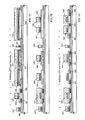
FIG. 33 is a graph showing ID-VG curves and μFE of an n-channel TFT.
FIG. 34 is a graph showing the relation between degradation rate of the μFE and the Lov region length of the n-channel TFT.
FIGS. 35A and 35B are graphs showing time dependent change of current consumption and the lowest operation voltage.
FIG. 36 is a graph showing ID-VG curves and μFE of an n-channel TFT.
FIG. 37 is a graph showing the relation between degradation rate of the μFE and the Lov region length of the n-channel TFT.
FIGS. 38A and 38B are graphs showing time dependent change of current consumption and the lowest operation voltage.
DESCRIPTION OF THE PREFERRED EMBODIMENTS
Hereinafter, preferred embodiments of the present invention will be explained in detail with reference to Examples thereof.
Example 1
The first example will be explained with reference to FIGS. 1A to 1C, 2A to 2C and 3A to 3C. A method of simultaneously fabricating TFT of a pixel unit and TFT of a driving circuit disposed around the pixel unit will be explained.
FIG. 1A shows the formation step of active layers and a gate insulation film.
In FIG. 1A, a substrate 101 is preferably made of a glass substrate, a quartz substrate or a plastic substrate (inclusive of a plastic film). A silicon substrate or a metal substrate having an insulation film on the surface thereof can be used, too.
An underlying film 102 that comprises a silicon-containing insulation film (the term “insulation film” generically represents a silicon oxide film, a silicon nitride film and a silicon nitride oxide film in this specification) is formed by a plasma CVD process or a sputtering process to a thickness of 100 to 400 nm on the surface of the substrate 101 on which the TFTs are to be fabricated. The term “silicon nitride oxide film” used in this specification represents an insulation film expressed by the general formula SiOxNy (where 0<x and y<1) and containing silicon, oxygen and nitrogen in a predetermined proportion.
In this example, the underlying film 102 has a two-layered structure consisting of a silicon nitride film 102 that has a thickness within the range of 25 to 100 nm and is hereby 50 nm and a silicon oxide film 103 that has a thickness within the range of 50 to 300 nm and is hereby 150 nm. The underlying film 102 is disposed so as to prevent contamination of impurities from the substrate, and need not always be disposed when the quartz substrate is used.
Next, an amorphous silicon film having a thickness of 20 to 100 nm is formed on the underlying film 102 by a known film formation method. The amorphous silicon film is preferably subjected to a dehydrogenation treatment preferably at 400 to 550° C. for several hours, though the treatment temperature and time vary depending on the hydrogen content. A crystallization step is preferably carried out after the hydrogen content is lowered to not greater than 5 atomic %. Though the amorphous silicon film may be formed by other fabrication methods such as sputtering and vacuum deposition, impurity elements contained in the film such as oxygen and nitrogen are preferably lowered sufficiently. Because the underlying film and the amorphous silicon film can be formed by the same film formation method, they may be formed hereby continuously. When the underlying film is prevented from being exposed once to the atmospheric air after its formation, surface contamination can be prevented, and variance of characteristics of the resulting TFT can be reduced.
A process step of forming the crystalline silicon film from the amorphous silicon film may use a known laser crystallization technology or thermal crystallization technology. The crystalline silicon film may be formed by the thermal crystallization method using a catalytic element that promotes crystallization of silicon. Besides the amorphous silicon film, a micro-crystalline silicon film may be used or the crystalline silicon film may be directly deposited. Furthermore, the crystalline silicon film may be formed by using the known technology of SOI (Silicon On Insulators) that bonds single crystal silicon onto the substrate.
Unnecessary portions of the crystalline silicon film thus formed are etched away to form island-like semiconductor films (hereinafter called the “active layers”) 104, 105 and 106. Boron (B) may be doped in advance in a concentration of about 1×10¹⁵ to 1×1017 cm−3 into regions of the crystalline silicon film where n-channel TFT is to be formed, in order to control a threshold voltage.
Next, a gate insulation film 107 consisting essentially of silicon oxide or silicon nitride as the principal component is so formed as to cover the active layers 104, 105 and 106. The gate insulation film 107 is formed to a thickness of 10 to 200 nm, preferably 50 to 150 nm. For example, a silicon nitride oxide film is formed by a plasma CVD process to a thickness of 75 nm from N2O and SiH4 as the starting materials. This film is then oxidized thermally at 800 to 1,000° C. in an oxygen atmosphere or in a mixed atmosphere of oxygen and hydrochloric acid, giving a 115 nm-thick gate insulation film.
FIG. 1B shows the formation of an n region.
Resist masks 108, 109, 110 and 111 are formed over the surface of the active layers 104 and 106, the entire surface of the regions in which wiring is to be formed, and over a part of the active layer 105 (inclusive of the region which is to serve as the channel formation region). An n-type imparting impurity element is added to form a low concentration impurity region 112. This low concentration impurity region 112 is the impurity region for forming later an LDD region (which is called the “Lov region” in this specification with “ov” representing “overlap”) that overlaps with the gate wiring through the gate insulation film beneath the n-channel TFT of a CMOS circuit. The concentration of the impurity element for imparting the n-type that is contained in the resulting low concentration impurity region, is expressed by “n”. Therefore, the low concentration impurity region 112 can be paraphrased to the “n region” in this specification.
In this example, phosphorus is added by ion doping that excites phosphine (PH3) by plasma excitation without executing mass separation. An ion implantation method that executes mass separation may be used naturally. In this process step, phosphorus is added to the semiconductor layer beneath the gate insulation film 107 through this film 107. The phosphorus concentration to be doped is preferably within the range of 2×10¹⁶ to 5×10¹⁹ atoms/cm3, and is hereby 1×10¹⁸ atoms/cm3.
After the resist masks 108, 109, 110 and 111 are removed, heat-treatment is carried out at 400 to 900° C., preferably 550 to 800° C., for 1 to 12 hours in a nitrogen atmosphere so as to activate phosphorus that is doped. This activation may be effected by irradiating a laser beam. Though this process step can be omitted, a higher activation ratio can be expected if this step is conducted.
FIG. 1C shows the formation of conductive films for gate wirings.
A first conductive film 113 is formed to a thickness of 10 to 100 nm by using an element selected from the group consisting of tantalum (Ta), titanium (Ti), molybdenum (Mo) and tungsten (W), or conductive materials of any of these elements as the principal component. Tantalum nitride (TaN) or tungsten nitride (WN), for example, is preferably used for the first conductive film 113.
A second conductive film 114 is formed to a thickness of 100 to 400 nm on the first conductive film 113 by using an element selected from the group consisting of Ta, Ti, Mo and W, or a conductive material of any of these elements as the principal component. For example, Ta may be formed to a thickness of 200 nm. It is hereby effective to form a silicon film to a thickness of about 2 to 20 nm beneath the first conductive film 113 or on the second conductive film 114 in order to prevent oxidation of the conductive films 113 and 114 (particularly, the conductive film 114).
FIG. 2A shows the formation of a p-channel gate wiring and the formation of p++ regions.
After resist masks 115, 116, 117 and 118 are formed, the first conductive film and the second conductive film (which will be handled hereinafter as a laminate film) are etched, giving a gate wiring 119 (also called the “gate electrode”) of the p-channel TFT and gate wirings 120 and 121. Incidentally, the conductive films 122 and 123 are left non-etched in such a manner as to cover the entire surface of the region that is to serve as the n-channel TFT.
The resist masks 115, 116, 117 and 118 are left as the masks, and a process step of doping an impurity element for imparting the p-type is carried out for a part of the semiconductor layer 104 at which the p-channel TFT is formed. Boron is used hereby as the impurity element and is doped by an ion doping method using diborane (B2H6). (Needless to say, an ion implantation method may be employed, too.) In this instance, boron is doped in a concentration of 5×10²⁰ to 3×10²¹ atoms/cm3. Incidentally, the concentration of the p-type imparting impurity element contained in the resulting impurity region is hereby expressed as “p++”. Therefore, the impurity regions 124 and 125 can be paraphrased to the “p++ regions” in this specification.
Incidentally, in this process step, a process step may be carried out which etches away the gate insulation film 107 using the resist masks 115, 116, 117 and 118 to expose a part of the active layer 104 and then adds the p-type imparting impurity element. In this case, since the acceleration voltage may be low, damage to the active layer is small, and throughput can be improved.
FIG. 2B shows the formation of n-channel gate wirings.
After the resist masks 115, 116, 117 and 118 are removed, resist masks 126, 127, 128 and 129 are formed, and gate wirings 130 and 131 of the n-channel TFT are formed. At this time, the gate wiring 130 is formed in such a manner as to overlap with the n region 112 through the gate insulation film 107.
FIG. 2C shows the formation of n+ regions.
The resist masks 126, 127, 128 and 129 are removed, and resist masks 132, 133 and 134 are formed afresh. A process step of forming an impurity region, that is to function as a source or drain region in each n-channel TFT, is carried out. The resist mask 134 is formed in such a manner as to cover the gate wiring 131 of the n-channel TFT to form the LDD region in such a manner that the gate wiring does not overlap with the n-channel TFT of the pixel unit in a subsequent process step.
An n-type imparting impurity element is added to form impurity regions 135, 136, 137, 138 and 139. Here, the ion doping method that uses phosphine (PH3) is employed. (Needless to say, the ion implantation method may be employed, as well.) The phosphorus concentration in this region is 1×10²⁰ to 1×10²¹ atoms/cm3. The concentration of the n-type imparting impurity element contained in the impurity regions 137, 138 and 139 is hereby expressed as “n+”. Therefore, the impurity regions 137, 138 and 139 in this specification can be paraphrased to the “n+ regions”. Strictly speaking, since the n region has been formed already, the impurity region 135 contains phosphorus in a somewhat higher concentration than the impurity regions 136, 137, 138 and 139.
In this process step, a step of adding the n-type imparting impurity element may be conducted after the gate insulation film 107 is etched using the resist masks 132, 133 and 134 and the gate wiring 130 as the masks to expose a part of the active layers 105 and 106. In this case, since the acceleration voltage may be low, damage to the active layer is small and throughput can be improved.
FIG. 3A shows the formation of n−− regions.
The resist masks 132, 133 and 134 are removed, and a process step of adding an n-type imparting impurity element to the active layer 106, that is to serve as the n-channel TFT, is carried out. The impurity regions 140, 141, 142 and 143 thus formed contain phosphorus in a concentration of ½ to 1/10 (more concretely, 1×10¹⁶ to 5×10¹⁸ atoms/cm3) of the n region described above. Incidentally, the concentration of the n-type imparting impurity element contained in these impurity regions 140, 141, 142 and 143 is hereby expressed by “n−−”. Therefore, the impurity regions 140, 141, 142 and 143 can be paraphrased to the “n−− regions” in this specification. In this process step, phosphorus is added in the concentration of n−− into all the impurity regions except for the impurity region 167 that is hidden by the gate wiring. However, this concentration n−− can be neglected because it is extremely low.
FIG. 3B shows a thermal activation step.
A protective insulation film 144, that is to serve later as a first inter-layer insulation film, is formed. The protective insulation film 144 may be a silicon nitride film, a silicon oxide film, a silicon nitride oxide film or their laminate film. The film thickness may be within the range of 100 to 400 nm.
A heat-treatment step is carried out in order to activate the n-type or p-type imparting impurity element added in each concentration. This process step can be conducted by a furnace annealing method, a laser annealing method, or a rapid thermal annealing method (RTA). This example uses the furnace annealing method. The heat-treatment is carried out in a nitrogen atmosphere at 300 to 650° C., preferably 400 to 550° C., and hereby 450° C., for 2 hours.
A heat-treatment is further carried out in an atmosphere containing 3 to 100% hydrogen at 300 to 450° C. for 1 to 12 hours so as to hydrogenate the active layer. This is the process step for terminating the dangling bonds of the semiconductor layer by hydrogen that is heated and excited. Plasma hydrogenation (using hydrogen that is excited by plasma) may be employed as another means for hydrogenation.
FIG. 3C shows the formation of inter-layer insulation films, source/drain wirings, a shading film, a pixel electrode and a holding capacitance.
After the activation step is completed, a 0.5 to 1.5 μm-thick inter-layer insulation film 145 is formed on the protective insulation film 144. A laminate film comprising the protective insulation film 144 and the inter-layer insulation film 145 is used as the first inter-layer insulation film.
Thereafter, contact holes reaching the source or drain regions of the TFT are bored, and source wirings 146, 147 and 148 and drain wirings 149 and 150 are formed. In this example, the source wirings and the drain wirings comprise a three-layered laminate film that is formed continuously by sputtering a Ti film having a thickness of 100 nm, a Ti-containing aluminum film having a thickness of 300 nm and a Ti film having a thickness of 150 nm. Incidentally, a laminate film of a copper film and a titanium nitride film may be used as the source wirings and the drain wirings.
Next, a silicon nitride film, a silicon oxide film or a silicon nitride oxide film is formed as a passivation film 151 to a thickness of 50 to 500 nm (typically, 200 to 300 nm). When hydrogenation treatment is carried out under this condition, desired results can be obtained for improving characteristics of the TFT. Similar effects can be obtained, for instance, when heat-treatment is carried out in an atmosphere containing 3 to 100% hydrogen at 300 to 450° C. for 1 to 12 hours, or by the plasma hydrogenation method. Open portions may be formed in the passivation film 151 at positions where contact holes for connecting the pixel electrodes to the drain wirings are to be later formed.
Next, a second inter-layer insulation film 152 made of an organic resin is formed to a thickness of about 1 μm. Polyimide, acrylic, polyamide, polyimideamide, BCB (benzocyclobutene), etc. can be used as the organic resin. The advantages brought forth by using the organic resin film are that the film formation method is simple, the parasitic capacitance can be reduced because a specific dielectric constant is low, and planarity is high. Organic resin films other than those described above and organic SiO compounds can be used, too. This example uses polyimide of the type that can be polymerized thermally after the application to the substrate, and the film is formed by firing at 300° C.
Next, the shading film 153 is formed on the second inter-layer insulation film 152 in the region that is to serve as the pixel unit. The shading film 153 is made of the element selected from the group consisting of aluminum (Al), titanium (Ti) and tantalum (Ta), or a material containing any of them as the principal component, and the film is formed to a thickness of 100 to 300 nm. An oxide (oxide film) 154 is formed to a thickness of 30 to 150 nm (preferably, 50 to 75 nm) on the surface of the shading film 153 by an anodic oxidation method or a plasma oxidation method. This example uses the aluminum film or the film consisting essentially of aluminum as the principal component for the shading film 153 and the aluminum oxide film (alumina film) for the oxide 154.
Though the insulation film is deposited only to the surface of the shading film in this example, the insulation film may be formed by the gaseous phase method such as the plasma CVD method, the thermal CVD method or the sputtering method. In such a case, too, the film thickness is preferably 30 to 150 nm (preferably, 50 to 75 nm). A silicon oxide film, a silicon nitride film, a silicon nitride oxide film, a DLC (Diamond-like Carbon) film or an organic resin film may be used. Furthermore, a laminate film combining these films may be used, too.
Next, contact holes reaching the drain wiring 150 are formed in the second inter-layer insulation film 152, thereby forming a pixel electrode 155. Incidentally, pixel electrodes 156 and 157 are the pixel electrodes of other adjacent pixels. The pixel electrodes 155, 156 and 157 are formed of a transparent conductive film in the case of fabricating a transmission type liquid crystal display device, and are formed of a metal film in the case of fabricating a reflection type liquid crystal display device. Here, a film consisting essentially of a compound between indium oxide and tin oxide (called “ITO”) is fabricated by sputtering to a thickness of 100 nm in order to obtain the transmission type liquid crystal display device.
At this time, the region 158 at which the pixel electrode 155 and the shading film 153 overlap with each other through the oxide 154 constitutes a holding capacitance.
In this way, the CMOS circuit for forming the driving circuit and the active matrix substrate having the pixel unit are completed on the same substrate. Incidentally, the n-channel TFT 181 and the p-channel TFT 182 are formed in the CMOS circuit that constitutes the driving circuit, and the pixel TFT 183 comprising the n-channel TFT is formed in the pixel unit.
In the p-channel TFT 181 of the CMOS circuit, the channel formation region 161, the source region 162 and the drain region 163 are formed. Each of the source region 162 and the drain region 163 is formed of the p++ region. In the n-channel TFT 182, the channel formation region 164, the source region 165, the drain region 166 and the LDD region (Lov region) 167 that wholly overlaps with the gate wiring through the gate insulation film are formed. At this time, the source region 165 and the drain region 166 are the n+ regions, and the Lov region 167 is the n region. More strictly, the drain region 166 is a (n+n+) region.
Referring to FIG. 3C, the Lov region is shown disposed only on one side of the channel formation region 164 (only on the drain region side) in order to reduce the resistance component as much as possible. However, the Lov region may be disposed on both sides while sandwiching the channel formation region 164 between them.
Formed in the pixel TFT 183 are the channel formation regions 168 and 169, the source region 170, the drain region 171, the LDD regions not overlapping with the gate wiring through the gate insulation film (this LDD region will be called hereinafter the “Loff region”; “off” represents hereby “offset”) 172, 173, 174 and 175, and the n+ region 176 (which is effective for reducing the OFF current value) that keeps contact with the Loff regions 173 and 174. At this time, the source region 170 and the drain region 171 comprise the n+ region, respectively, and the Loff regions 172, 173, 174 and 175 comprise the n−− region, respectively.
This invention can optimize the structure of the TFT for forming each circuit in accordance with the circuit specification required by the pixel unit and by the driving circuit, and can improve operation performance of the semiconductor device and its reliability. Speaking more concretely, the arrangement of the LDD regions is rendered different for the n-channel TFTs in accordance with the circuit specification, and the TFT structure making the most of the high speed operation or the countermeasure for the hot carrier and the TFT structure making the most of the low OFF current operation are accomplished on the same substrate because the Lov regions and the Loff regions are skillfully arranged.
In the case of the active matrix type liquid crystal display device, for example, the n-channel TFT 182 is suitable for a logic circuit such as a shift register circuit, a frequency division circuit, a signal division circuit, a level shifter circuit or a buffer circuit, for which the high speed operation is of importance. The n-channel TFT 183 is suitable for the pixel unit, a sampling circuit (called also a “transfer gate”), etc, for which the low OFF current operation is of importance.
The length (width) of the Lov region is from 0.5 to 3.0 μm for the channel length of 3 to 7 μm, typically 1.0 to 1.5 μm. The length (width) of the Loff regions 172, 173, 174 and 175 disposed in the pixel TFT 183 is 0.5 to 3.5 μm, typically 2.0 to 2.5 μm.
Example 2
In this example, another structure of the holding capacitance connected to the n-channel TFT 401 of the pixel unit of the active matrix substrate will be explained with reference to FIG. 4. Incidentally, the sectional structure shown in FIG. 4 is entirely the same as that of Example 1 up to the process step of forming the oxide 154, and the structure up to this step has been explained already with reference to FIGS. 1A to 1C, 2A to 2C and 3A to 3C. Therefore, only the difference of this example from Example 1 will be explained.
After the shading film 153 and the oxide 154 obtained by oxidizing the shading film 153 are formed in accordance with the process steps of Example 1, spacers 402, 403 and 404 comprising an organic resin film are formed. A film selected from the group consisting of polyimide, polyamide, polyimideamide, acrylic and BCB (benzocyclobutene) can be used for the organic resin film. Thereafter, the spacer 402, the second inter-layer insulation film 152 and the passivation film 151 are etched to form contact holes, and the pixel electrode 405 is formed using the same material as that of Example 1. Incidentally, the pixel electrodes 406 and 407 are the pixel electrodes of other adjacent pixels.
In this way, the holding capacitance 408 is formed in the region where the shading film 153 and the pixel electrode 405 overlap with each other through the oxide 154. Because the spacers 402, 403 and 404 are disposed in the manner described above, short-circuit that would otherwise occur between the shading film 153 and each pixel electrode 405, 406 and 407 can be prevented.
Incidentally, the construction of this example can be combined with the construction of Example 1.
Example 3
In this example, still another structure of the holding capacitance connected to the n-channel TFT of the pixel unit of the active matrix substrate will be explained with reference to FIGS. 5A to 5C. Incidentally, the sectional structure shown in FIGS. 5A to 5C is exactly the same as that of Example 1 up to the process step of forming the shading film 153, and the structure up to this process step has been explained already with reference to FIGS. 1A to 1C, 2A to 2C and 3A to 3C. Therefore, only the difference of this example from Example 1 will be explained.
After the shading film 153 is formed in accordance with the process steps of Example 1, spacers 501, 502 and 503 comprising an organic resin film are formed in such a manner as to cover the end portions of the shading film 153. A film selected from the group consisting of polyimide, polyamide, polyimideamide, acrylic and BCB (benzocyclobutene) can be used for the organic resin film (FIG. 5A).
Next, an oxide 504 is formed on the exposed surface of the shading film 153 by the anodic oxidation method or the plasma oxidation method. Incidentally, the oxide 504 is not formed at the contact portions with the spacers 501, 502 and 503 (FIG. 5B).
Next, the spacer 501, the second inter-layer insulation film 152 and the passivation film 151 are etched to form a contact hole, and a pixel electrode 505 is formed using the same material as that of Example 1. The pixel electrodes 506 and 507 are the pixel electrodes of other adjacent pixels.
In this way, the holding capacitance 508 is formed in the region where the shading film 153 and the pixel electrode 505 overlap with each other through the oxide 504. Because the spacers 501, 502 and 503 are provided, short-circuit that would otherwise occur between the shading film 153 and each pixel electrode 505, 506 and 507 can be prevented.
Incidentally, the construction of this example can be combined with the construction of Example 1.
Example 4
In this example, a method of fabricating an active matrix substrate having a pixel unit and a CMOS circuit as the basic form of a driving circuit disposed in the periphery of the pixel unit, that are formed simultaneously, will be explained with reference to FIGS. 6A to 6D, 7A to 7C and 8A to 8C.
To begin with, a silicon nitride oxide film 602 a is formed as an underlying film on a substrate 601 to a thickness of 50 to 500 nm, typically 100 nm. The silicon nitride oxide film 602 a is formed using SiH4, N2O, and NH3 as the starting material gas, and the nitrogen concentration of this film is adjusted to at least 25 atomic % to less than 50 atomic %. Heat-treatment is then carried out in a nitrogen atmosphere at 450 to 650° C. in order to render the silicon nitride oxide film 602 a compact.
A silicon nitride oxide film 602 b is further formed to a thickness of 100 to 500 nm, typically 200 nm, and an amorphous semiconductor film (not shown) is continuously formed to a thickness of 20 to 80 nm. This example uses an amorphous silicon film for the amorphous semiconductor film, but a micro-crystalline silicon film or an amorphous silicon-germanium film may be used, as well.
The amorphous silicon film is then crystallized by crystallization means described in Japanese Patent Laid-Open No. 7-130652 (corresponding to U.S. Pat. Nos. 5,643,826 and 5,923,962), forming a crystalline silicon film that is not shown. The technology disclosed in this prior art reference is the crystallization means that uses catalytic elements for promoting crystallization (at least one member selected from the group consisting of nickel, cobalt, germanium, tin, lead, palladium, iron and copper; typically nickel) for crystallizing the amorphous silicon film. More concretely, the reference invention conducts heat-treatment under the condition where the catalytic element is supported on the surface of the amorphous silicon film to convert the amorphous silicon film to the crystalline silicon film.
After the crystalline silicon film is formed in this way, the remaining amorphous component is crystallized as an excimer laser beam is radiated to improve crystallinity of the entire film. Incidentally, the excimer laser beam may be of a pulse oscillation type or a continuous oscillation type. When the beam is processed into a linear shape and radiated, a large substrate can be processed, too.
Next, the crystalline silicon film is patterned to form active layers 603, 604, 605 and 606, and a gate insulation film 607 is so formed as to cover these active layers 603 to 606. The gate insulation film 607 is a silicon nitride oxide film prepared from SiH4 and N2O, and is formed to a thickness of 10 to 200 nm, preferably 50 to 150 nm (FIG. 6A).
Resist masks 608, 609, 610 and 611 are then formed in such a fashion as to cover the entire surface of the active layers 603 and 606 and apart of the active layers 604 and 605 (inclusive of the channel formation region). After an n-type imparting impurity element (phosphorus in this example) is doped by the ion doping method that uses phosphine (PH3), n regions 612, 613 and 614 that are to serve as the Lov region or the Loff region are formed. Since phosphorus is added to the active layers beneath the gate insulation film 607 through this film 607, an acceleration voltage is set to 65 keV. The concentration of phosphorus added to the active layers is preferably within the range of 2×10¹⁶ to 5×10¹⁹ atoms/cm3, and is hereby 1×10¹⁸ atoms/cm3 (FIG. 6B).
Next, tantalum nitride (TaN) is sputtered to form a first conductive film 615. Subsequently, a second conductive film 616 consisting essentially of aluminum (Al) as the principal component is formed to a thickness of 100 to 300 nm (FIG. 6C).
The second conductive film 616 is etched to form a wiring 617. Since the second conductive film is made of Al in this example, a selection ratio to the TaN film as the underlying film by a phosphoric acid solution is excellent. A third conductive film 618 of tantalum (Ta) is formed to a thickness of 100 to 400 nm (to 200 nm in this example) over the first conductive film 615 and the wiring 617. A tantalum nitride film may be formed further on this tantalum film 618 (FIG. 6D).
Next, resist masks 619, 620, 621, 622, 623 and 624 are formed. A part of the first and third conductive films is etched away to form a connection wiring 625 having a low resistance, a gate wiring 626 of the p-channel TFT and a gate wiring 627 of the pixel unit. The conductive films 628, 629 and 630 are left on the region that is to serve as the n-channel TFT. The connection wiring 625 is formed at a portion at which the wiring resistance is minimized (for example, a wiring portion from input/output terminals of external signals to input/output terminals of the driving circuit). Because the wiring width becomes great to a certain extent from the structural limitation, the connection wiring is not suitable for the portion that requires a miniature wiring.
The first conductive film (TaN film) and the second conductive film (Ta film) can be etched by a mixed gas of CF4 and O2. While the resist masks 619, 620, 621, 622, 623 and 624 are left as they are, a process step of doping a p-type imparting impurity element to a part of the active layer 603 at which the p-channel TFT is formed. Here, boron is used as the impurity element, and ion doping using diborane (B2H6) is carried out. (Needless to say, ion implantation can be used, too.) The boron concentration is 5×10²⁰ to 3×10²¹ atoms/cm3 (2×10²¹ atoms/cm3 in this example). In this way, there are formed p++ regions 631 and 632 containing boron in a high concentration (FIG. 7A).
In this process step, it is also possible to conduct the process step that etches the gate insulation film 107 using the resist masks 619, 620, 621, 622, 623 and 624 as the mask to expose a part of the active layer 603 and then to add boron. In this case, since the acceleration voltage may be low, damage to the active layer is small and throughput can be improved.
Next, after the resist masks 619, 620, 621, 622, 623 and 624 are removed, resist masks 633, 634, 635, 636, 637 and 638 are formed afresh. They are for forming the gate wiring of the n-channel TFTs, and gate wirings 639, 640 and 641 of the n-channel TFTs are formed. At this time, the gate wirings 639 and 640 are formed in such a manner as to overlap with a part of the n regions 612, 613 and 614 (FIG. 7B).
Next, after the resist masks 633, 634, 635, 636, 637 and 638 are removed, resist masks 642, 643, 644, 645, 646 and 647 are formed afresh. The resist masks 644 and 646 are so formed as to cover the gate wirings 640 and 641 and a part of the n regions 612, 613 and 614.
An n-type imparting impurity element (phosphorus in this example) is added in a concentration of 1×10²⁰ to 1×10²¹ atoms/cm3 (5×10²⁰ atoms/cm3 in this example) to form n+ regions 647, 648, 649, 650, 651, 652 and 653 in the active layers 604, 605 and 606 (FIG. 7C).
In this process step, it is also possible to conduct a process step that etches away the gate insulation film 107 using the resist masks 642, 643, 644, 645, 646 and 647 to expose a part of the active layers 604, 605 and 606 and then adds phosphorus. In this case, since the acceleration voltage may be low, damage to the active layers is small and throughput can be improved.
After the resist masks 642, 643, 644, 645 and 646 are removed, a process step of adding an n-type imparting impurity element (phosphorus in this example) to the active layer 606, that is to serve as the n-channel TFT of the pixel unit, is carried out. In this way, n−− regions 654, 655, 656 and 657 to which phosphorus is added in a concentration of ½ to 1/10 (concretely, 1×10¹⁶ to 5×10¹⁸ atoms/cm3) of the concentration of the n region are formed (FIG. 8A).
In this process step, phosphorus is added in the concentration of n−− to all the impurity regions other than the impurity regions 658, 659 and 660 that are hidden by the gate wiring. In practice, the concentration of n−− is so low that it may be neglected. Strictly speaking, however, the regions represented by reference numerals 659 and 660 are the n regions whereas the regions represented by reference numerals 661 and 662 are the (n+n−−) regions that contain phosphorus in a somewhat higher concentration than the n regions 659 and 660.
Next, a protective insulation film 663 having a thickness of 100 to 400 nm is formed with a silicon nitride oxide film that is formed by the plasma CVD method using SiH4, N2O and NH3 as the starting materials. This silicon nitride oxide film is preferably formed so that its hydrogen concentration is 1 to 30 atomic %. A silicon oxide film, a silicon nitride film and their laminate film may be used for the protective insulation film 663.
Thereafter, a heat-treatment step is carried out so as to activate the n-type or p-type imparting impurity element added in a respective concentration. This step can be carried out in accordance with the furnace annealing method, the laser annealing method or the rapid thermal annealing method (RTA method). This example employs the furnace annealing method for the activation treatment. The heat-treatment is carried out in a nitrogen atmosphere at 300 to 650° C., preferably 400 to 550° C., and at 450° C. in this example, for 2 hours.
A heat-treatment is further carried out in an atmosphere containing 3 to 100% hydrogen, at 300 to 450° C. for 1 to 12 hours so as to hydrogenate the active layers. This is the step that terminates the dangling bonds of the semiconductor layer by hydrogen that is thermally excited. Plasma hydrogenation (using hydrogen that is excited by plasma) may be used as another hydrogenation means (FIG. 8B).
After the activation step is completed, a 0.5 to 1.5 μm-thick inter-layer insulation film 664 is formed on the protective insulation film 663. A laminate film comprising the protective insulation film 663 and the inter-layer insulation film 664 is used as the first inter-layer insulation film.
Contact holes reaching the source region or the drain region of the respective TFT are bored, and the source wirings 665, 666, 667 and 668 and the drain wirings 669, 670, 671 and 672 are formed. Incidentally, the drain wirings 669 and 670 are connected as the same wiring in order to form the CMOS circuit, though they are not shown in the drawings. Connection wirings 673 and 674 that connect the input/output terminals with one another and circuits with one another are formed simultaneously. These wirings in this example comprise a laminate film having a three-layered structure of a 100 nm-thick Ti film, a 300 nm-thick Ti-containing aluminum film and a 150 nm-thick Ti film that are continuously formed by sputtering, though this laminate film is not shown in the drawings.
Next, a passivation film 675 is constituted by a silicon nitride film, a silicon oxide film or a silicon nitride oxide film each having a thickness of 50 to 500 nm (typically, 200 to 300 nm). This passivation film 675 may be formed from the silicon nitride oxide film prepared from SiH4, N2O and NH3 by plasma CVD, or a silicon nitride film prepared from SiH4, N2 and NH3.
Prior to the formation of the film, a hydrogenation step is carried out by a plasma hydrogenation treatment by introducing N2O, N2, NH3, or the like. Hydrogen that is excited by this plasma treatment is supplied into the first inter-layer insulation film. As the substrate is heated to 200 to 400° C., hydrogen can be diffused into the lower layer side, too, and the active layers can be thus hydrogenated. The fabrication condition of the passivation film is not particularly restrictive, but the film is preferably a close film.
The hydrogenation step may be further carried out after the passivation film is formed. Similar effects can be obtained by, for example, carrying out heat-treatment in an atmosphere containing 3 to 100% hydrogen at 300 to 450° C. for 1 to 12 hours, or by the plasma hydrogenation method. In this instance, openings may be formed in the passivation film 151 at positions where contact holes for connecting the pixel electrodes to the drain wiring are to be formed afterwards.
A second inter-layer insulation film 676 made of an organic resin is then formed to a thickness of about 1 μm. Polyimide, acrylic, polyamide, polyimideamide or BCB (benzocyclobutene) can be used as the organic resin. The advantages brought forth by the use of the organic resin film are that the formation method of the film is simple, the parasitic capacitance can be reduced because the specific dielectric constant is low, and planarity is high. Organic resin films other than those described above and organic SiO compounds can be used, too. This example uses polyimide of the type that is thermally polymerized after being applied to the substrate, and the film is fabricated by firing the resin at 300° C.
Next, a shading film 677 is formed on the second inter-layer insulation film 676 in a region that is to serve as the pixel unit. The shading film 153 is a film made of the element selected from the group consisting of aluminum (Al), titanium (Ti) and tantalum (Ta), or a film consisting of any of these elements as the principal component. The film is formed to a thickness of 100 to 300 nm. If an insulation film such as silicon oxide film is formed to a thickness of 5 to 50 nm on the second inter-layer insulation film 676, adhesion of the shading film to be formed on the second inter-layer insulation film 676 can be improved. If a plasma treatment using a CF4 gas is applied to the surface of the second inter-layer insulation film 676 made of the organic resin, adhesion of the shading film to be formed on this film 676 can be improved through surface modification.
Other connection wiring can be formed besides the shading film. For example, the connection wiring for connecting circuits with one another inside the driving circuit can be formed. In this case, however, the contact holes must be bored in advance before the materials for shaping the shading film or the connection wiring are formed.
Next, an anodic oxide 678 is formed on the surface of the shading film 677 to a thickness of 30 to 150 nm (preferably, 50 to 75 nm) by an anodic oxidation method or a plasma oxidation method (by the anodic oxidation method in this example). Since this example uses an aluminum film or a film consisting essentially of aluminum as the principal component for the shading film 677, an aluminum oxide film (alumina film) is formed as the anodic oxide 678.
To conduct the anodic oxidation treatment, an ethylene glycol tartrate solution having a sufficiently low alkali ion concentration is first prepared. This is the solution prepared by mixing a 15% aqueous ammonium tartrate solution with ethylene glycol at a mixing ratio of 2:8, and aqueous ammonia is added to this solution to adjust the pH to 7±0.5. A platinum electrode to serve as a cathode is dipped into this solution, and the substrate having the shading film 677 formed thereon is then immersed. A predetermined DC current (several to dozens of mA) is applied with the shading film 677 as the anode. The voltage between the cathode and the anode in the solution changes with time and with the growth of the oxide. However, the voltage is regulated so that the current remains constant, and the voltage is kept constant at the point when the voltage reaches 150 V. This constant voltage is kept for 15 minutes. In this way, an anodic oxide having a thickness of 50 to 75 nm can be formed on the surface of the shading film 677. Incidentally, the numerical values relating to the anodic oxidation method illustrated hereby are merely illustrative, and the optimum values naturally change in accordance with the size of the device to be fabricated, and other factors.
This example employs the construction in which the insulation film is disposed only on the surface of the shading film. However, the insulation film may be formed by the gaseous phase method such as the plasma CVD method, the thermal CVD method or the sputtering method. In such a case, too, the film thickness is 30 to 150 nm (preferably, 50 to 75 nm)). The insulation film may use a silicon oxide film, a silicon nitride film, a silicon nitride oxide film, a DLC (Diamond-Like Carbon) film or an organic resin film. Furthermore, a laminate film of these films may be also used.
Next, contact holes reaching the drain wiring 672 are bored in the second inter-layer insulation film 676 and the passivation film 675 so as to form the pixel electrode 679. Incidentally, pixel electrodes 680 and 681 are the pixel electrodes of other adjacent pixels. A transparent conductive film is used as the pixel electrodes 679, 680 and 681 when a transmission type liquid crystal display device is fabricated. A metal film is used as the pixel electrodes when a reflection type liquid crystal display device is fabricated. In this example, a film of a compound of indium oxide and tin oxide (ITO) is formed to a thickness of 100 nm by sputtering to fabricate the transmission type liquid crystal display device.
At this time, a region in which the pixel electrode 679 and the shading film 677 overlap with each other through the anodic oxide 678 forms the holding capacitance.
In this way, the active matrix substrate having the CMOS circuit to serve as the driving circuit and the pixel unit on the same substrate is completed. In the driving circuit are formed the p-channel TFT 801 and the n- channel TFTs 802 and 803, and in the pixel unit is formed the pixel TFT 804 comprising the n-channel TFT (FIG. 8C).
In the p-channel TFT 801 of the CMOS circuit, the channel formation region 701, the source region 702 and the drain region 703 are formed. Each of the source region 702 and the drain region 703 is formed of the p++ region.
In the n-channel TFT 802 are formed the channel formation region 704, the source region 705, the drain region 706, and the Lov region 707 on one of the sides of the channel formation region. At this time, the source region 705 and the drain region 706 are formed of the (n+n+) region, and the Lov region 707 is formed of n region. The Lov region 707 is formed in such a manner as to fully overlap with the gate wiring.
In the n-channel TFT 803 are formed the channel formation region 708, the source region 709, the drain region 710, and the Lov regions 711 a, 712 a and the Loff regions 711 b and 712 b on both sides of the channel formation region. In this instance, the source region 709 and the drain region 710 are formed of the (n+n+) region, respectively. The Lov regions 711 a and 712 a are formed of the n region, and the Loff regions 711 b and 712 b are formed of the (n−−+n) region. According to this construction, the Lov regions and the Loff regions are accomplished because a part of the LDD region is so arranged as to overlap with the gate wiring.
In the pixel TFT 804 are formed the channel formation regions 713 and 714, the source region 715, the drain region 716, the Loff regions 717, 718, 719 and 720 and the n+ region 721 keeping contact with the Loff regions 718 and 719. At this time, the source region 715 and the drain region 716 are formed of the n+ region, respectively, and the Loff regions 717, 718, 719 and 720 are formed of the n−− region.
This example optimizes the structure of the TFTs for forming each circuit in accordance with the circuit specifications required for the pixel unit and for the driving circuit, and can improve operation performance and reliability of the semiconductor device. More concretely, the LDD region of the n-channel TFT is arranged in a different way in accordance with the circuit specification, and the TFT structure that lays stress on the high-speed operation or on the countermeasure against the hot carriers, and the TFT structure that lays stress on the low OFF current operation, are accomplished on the same substrate.
When the active matrix type liquid crystal display device is considered, for example, the n-channel TFT 802 is suitable for the logic circuit that requires the high speed operation such as a shift register circuit, a frequency division circuit, a signal division circuit, a level shifter circuit and a buffer circuit. In other words, the n-channel TFT employs the structure that arranges the Lov region only on one of the sides (the drain region side) of the channel formation region, and thus lays stress on the countermeasure against the hot carrier while the resistance component is reduced as much as possible. This is because the function of the source region is the same as that of the drain region in the group of the circuits described above and the moving direction of the carriers (electrons) is constant. However, the Lov regions can be arranged on both sides of the channel formation region, whenever necessary.
The n-channel TFT 803 is suitable for a sampling circuit (sample-and-hold circuit) that requires both of the countermeasure against the hot carriers and the low OFF current operation. In other words, the countermeasure against the hot carriers is achieved as the Lov region is disposed and the low OFF current operation is achieved as the Loff region is disposed. In the sampling circuit, the function of the source region is reversed to that of the drain region and the moving direction of the carriers changes by 180°. Therefore, the structure must have symmetry of line with the gate wiring as the center. Incidentally, only the Lov region is disposed depending on cases.
The n-channel TFT 804 is suitable for the pixel unit and the sampling circuit (sample-and-hold circuit) that lays stress on the low OFF current operation. In other words, the Lov region that might increase the OFF current value is not disposed but only the Loff region is disposed so as to attain the low OFF current operation. The LDD region having a lower concentration than that of the LDD region of the driving circuit is used as the Loff region so that even when the ON current value drops to a certain extent, the OFF current value can be reduced as much as possible. Furthermore, it has been confirmed that the n+ region 721 is extremely effective for reducing the OFF current value.
The length (width) of the Lov region 707 of the n-channel TFT 802 may be 0.5 to 3.0 μm, typically 1.0 to 1.5 μm, for the channel length of 3 to 7 μm. The length (width) of the Lov regions 711 a and 712 a of the n-channel TFT 803 may be 0.5 to 3.0 μm and typically 1.0 to 1.5 μm. The length (width) of the Loff regions 711 b and 712 b may be 1.0 to 3.5 μm and typically 1.5 to 2.0 μm. The length (width) of the Loff regions 717, 718, 719 and 720 disposed in the pixel TFT 804 may be 0.5 to 3.5 μm and typically 2.0 to 2.5 μm.
It is another feature of the present invention that the p-channel TFT 801 is formed in self-alignment and the n- channel TFTs 802, 803 and 804 are formed in non-self-alignment.
Incidentally, this example is based on the construction of the active matrix substrate explained in Example 1 and only the structure of the n-channel TFT 803 is added to this construction. Therefore, the conditions of the thin film materials during the fabrication process, the range of the numerical values of the impurity doping process, the range of the film thickness of the thin films, and so forth, explained in Example 1, can be as such used in this example, too. The construction of this example can be combined with the construction of Example 2 or Example 3.
Example 5
In this example, the fabrication process of fabricating an active matrix type liquid crystal display device from an active matrix substrate will be explained. As shown in FIG. 9, an orientation film 901 is formed on the substrate under the condition shown in FIG. 8C. A polyimide resin is used in most cases for the orientation film of the liquid crystal display device. A transparent conductive film 903 and an orientation film 904 are formed on an opposing substrate 902. After the orientation films are formed, rubbing treatment is carried out so that the liquid crystal molecules are oriented with a certain predetermined pre-tilt angle. The active matrix substrate having the pixel unit and the CMOS circuit formed thereon and the opposing substrate are bonded to each other through a sealing material or a spacer (both being not shown) by a known cell assembly step. Thereafter, a liquid crystal material 905 is charged between both substrates and is completely sealed by a sealant (not shown). A known liquid crystal material may be used as the liquid crystal material. In this way, the active matrix type liquid crystal display device shown in FIG. 9 is completed.
Next, the construction of this active matrix type liquid crystal display device will be explained with reference to a perspective view of FIG. 10 and top views of FIGS. 11A and 11B. Incidentally, common reference numerals will be used because FIGS. 10, 11A and 11B correspond to the structural sectional view of FIGS. 6A to 6D, 7A to 7C and 8A to 8C. The sectional structure along a line A-A′ shown in FIG. 11B corresponds to the sectional view of the pixel unit shown in FIG. 8C.
The active matrix substrate comprises a pixel unit 1001, a scanning (gate) line driving circuit 1002 and a signal (source) line driving circuit 1003 that are formed on a glass substrate 601. The pixel TFT 804 of the pixel unit is the n-channel TFT, and the driving circuit disposed in the periphery of the pixel unit comprises a CMOS circuit as a basic circuit. The scanning (gate) line driving circuit 1002 and the signal (source) line driving circuit 1003 are connected to the pixel unit 1001 by gate wiring 641 and source wiring 668, respectively. Connection wirings 625 and 673 are so disposed as to extend from external input/output terminals 1005, to which the FPC 1004 is connected, to input/output terminals of the driving circuit.
FIGS. 11A and 11B are top views showing a part (one pixel) of the pixel unit 1001. FIG. 11A is a top view showing in superposition the active layer, the gate wiring and the source wiring. FIG. 11B is a top view showing in superposition a shading film and a pixel electrode on the members shown in FIG. 11A. Referring to FIG. 11A, the gate wiring 641 crosses the active layer 606 below it through a gate insulation film, not shown. A source region, a drain region and an Loff region comprising an n−− region are formed in the active layer 606, though they are not shown in the drawings. Reference numeral 1101 denotes a contact portion between the source wiring 668 and the active layer 606 and reference numeral 1102 denotes a contact portion between the drain wiring 672 and the active layer 606.
In FIG. 11B, there are formed the shading film 677 having an anodic oxide (which is not hereby shown but corresponds to the anodic oxide 678 shown in FIG. 8C) formed on the pixel TFT and the pixel electrode 679, 680 and 681 for each pixel. A holding capacitance 682 is fabricated by the region in which the shading film 677 and the pixel electrode 679 overlap with each other through the anodic oxide. Incidentally, reference numeral 1103 denotes a contact portion between the drain wiring 672 and the pixel electrode 679.
This example uses an alumina film having a high specific dielectric constant of 7 to 9 for the dielectric of the holding capacitance, and can therefore reduce the area for securing the necessary capacitance. Furthermore, because this example uses the shading film formed on the pixel TFT as one of the electrodes of the holding capacitance, it can improve the aperture ratio of the image display part of the active matrix type liquid crystal display device.
Incidentally, the active matrix type liquid crystal display device of this example has been explained with reference to the construction explained in Example 4, but it can be freely combined with the construction of any of Examples 1, 2 and 3 so as to fabricate the active matrix type liquid crystal display device.
Example 6
The holding capacitance provided to each pixel of the pixel unit can be constituted by using the electrode, that is not connected to the pixel electrode (the shading film in the present invention), as the fixed potential. In such a case, the shading film is preferably kept under the floating condition (under the electrically isolated condition) or under the common potential (at an intermediate potential of the image signals that are sent as data).
In this example, therefore, a connection method when the shading film is fixed to the common potential will be explained with reference to FIGS. 12A and 12B. Referring to FIG. 12A, reference numeral 1201 denotes the pixel TFT that is fabricated in the same way as in Example 1, and reference numeral 1202 denotes the shading film that functions as one of the electrodes of the holding capacitance. The shading film 1202 extends outside the pixel unit and is connected to a power source line 1203 that gives the common potential through a contact hole 1206 bored in a second inter-layer insulation film 1204 and a passivation film 1205.
When the shading film 1202 is electrically connected to the power source line giving the common potential outside the pixel unit in this way, the common potential can be secured. In this case, therefore, a process step of etching the second inter-layer insulation film 1204 and the passivation film 1205 prior to the formation of the shading film 1202 becomes necessary.
Referring next to FIG. 12B, reference numeral 1207 denotes the pixel TFT that is fabricated in the same way as in Example 1, and reference numeral 1208 denotes the shading film that functions as one of the electrodes of the holding capacitance. The shading film 1208 extends outside the pixel unit and overlaps with a conductive film 1210 through an oxide 1211 in the region that is represented by reference numeral 1209. This conductive film 1210 is formed simultaneously with a pixel electrode 1212.
The conductive film 1210 is connected to a power source line 1216 giving a common potential through a contact hole 1215 that is bored in a second inter-layer insulation film 1213 and a passivation film 1214. At this time, a capacitor comprising the shading film 1208, the oxide 1211 and the conductive film 1210 is constituted in the region 1209. When driven by an AC, this capacitor undergoes substantial short-circuit. In other words, since the shading film 1208 and the conductive film 1210 are electrically connected to each other by electrostatic coupling in the region 1209, the shading film 1208 and the power source line 1216 are connected substantially to each other.
Since this example employs the construction shown in FIG. 12B, it can set the shading film to the common potential without increasing the number of process steps.
Incidentally, the construction of this example can be freely combined with the construction of any of Examples 1 to 5.
Example 7
FIG. 13 shows an example of the circuit construction of the active matrix substrate represented by Example 4. The active matrix substrate of this example includes a source signal line side driving circuit 1301, a gate signal line side driving circuit (A) 1307, a gate signal line side driving circuit (B) 1311, a pre-charge circuit 1312 and a pixel unit 1306. The source signal line side driving circuit 1301 includes a shift register circuit 1302, a level shifter circuit 1303, a buffer circuit 1304 and a sampling circuit 1305. The gate signal line side driving circuit (A) 1307 includes a shift register circuit 1308, a level shifter circuit 1309 and a buffer circuit 1310. The gate signal line side driving circuit (B) 1311 has a similar construction.
A driving voltage of each shift register circuit 1302, 1308 is 5 to 16 V (typically, 10V), and the n-channel TFT used for a CMOS circuit that constitutes the shift register circuit has suitably the structure represented by reference numeral 802 in FIG. 8C.
The level shifter circuits 1303 and 1309 and the buffer circuits 1304 and 1310 use a high driving voltage of 14 to 16 V. A CMOS circuit containing the n-channel TFT 802 shown in FIG. 8C is suitable for them in the same way as the shift register circuit. Incidentally, it is effective to use a double-gate structure for the gate wiring so as to improve reliability of the circuit.
The sampling circuit 1305 uses a driving voltage of 14 to 16 V. A CMOS circuit containing the n-channel TFT 803 shown in FIG. 8C is suitable because the source region is inverted relative to the drain region and moreover, the OFF current value must be reduced. Incidentally, the n-channel TFT and the p-channel TFT are combined with one another when the sampling circuit is fabricated in practice.
The pixel unit 1306 uses a driving voltage of 14 to 16 V. A lower OFF current value is required for this pixel unit 1306 than for the sampling circuit 1305. Therefore, a complete LDD structure (in which the Lov region is not disposed) is preferably employed, and the n-channel TFT 804 shown in FIG. 8C is preferably used, too.
The construction of this example can be freely combined with the construction of any of Examples 2 to 6.
Example 8
In this example, a process step of forming an active layer to function as an active layer of the TFT will be explained with reference to FIGS. 14A to 14E. To begin with, an underlying film 1402 comprising a 200 nm-thick silicon nitride oxide film and a 50 nm-thick amorphous semiconductor film 1403 (an amorphous silicon film in this example) are continuously formed on a substrate 1401 (a glass substrate in this example) without exposing them to the atmospheric air.
Next, an aqueous solution (an aqueous nickel acetate solution) containing 10 ppm by weight of a catalytic element (nickel in this example) is applied by spin coating to form a catalytic element-containing layer 1404 on the entire surface of the amorphous semiconductor film 1403. Examples of the catalytic elements that can be used in this example include germanium (Ge), iron (Fe), palladium (Pd), tin (Sn), lead (Pb), cobalt (Co), platinum (Pt), copper (Cu) and gold (Au) (FIG. 14A) besides nickel (Ni).
Though this example employs a spin coating as the method of adding nickel, a thin film (a nickel film in this example) of a catalytic element may be formed by a vapor deposition or a sputtering on the surface of the amorphous semiconductor film.
Next, prior to the crystallization step, a heat-treatment step is carried out at 400 to 500° C. for about 1 hour so as to dissociate hydrogen from inside the film. A heat-treatment is further carried out at 500 to 650° C. (preferably at 550 to 570° C.) for 4 to 12 hours (preferably for 4 to 6 hours). In this example, this heat-treatment is carried out at 550° C. for 4 hours to form a crystalline semiconductor film (a crystalline silicon film in this example) 1405 (FIG. 14B).
Next, a gettering step is carried out in order to remove nickel used in the crystallization step from the crystalline silicon film. First, a mask insulation film 1406 is formed to a thickness of 150 nm on the surface of the crystalline semiconductor film 1405, and an opening 1407 is bored by patterning. A process step of adding an element of the Group 15 of the Periodic Table (phosphorus in this example) to the exposed crystalline semiconductor film is carried out. This process step gives a gettering region 1408 containing phosphorus in a concentration of 1×10¹⁹ to 1×10²⁰ atoms/cm3 (FIG. 14C).
A heat-treatment is then carried out in a nitrogen atmosphere at 450 to 650° C. (preferably at 500 to 550° C.) for 4 to 24 hours (preferably for 6 to 12 hours). Due to this heat-treatment, nickel in the crystalline semiconductor film moves in a direction represented by an arrow in the drawing and is collected into the gettering region 1408 by the gettering operation of phosphorus. In other words, since nickel is removed from inside the crystalline semiconductor film, the nickel concentration in the crystalline semiconductor film 1409 can be lowered to 1×10¹⁷ atoms/cm3 or lower, preferably 1×10¹⁶ atoms/cm3 or lower (FIG. 14D).
After the mask insulation film 1406 is removed, patterning is conducted in such a manner as to completely remove the gettering region 1408 to acquire an active layer 1410. Incidentally, though FIG. 14E shows only one active layer 1410, a plurality of active layers are naturally formed simultaneously over the substrate.
Each active layer 1410 so formed comprises a crystalline semiconductor film having extremely high crystallinity because it uses the catalytic element (nickel in this example) for promoting crystallization. The catalytic element is removed by the gettering operation of phosphorus after crystallization, and the concentration of the catalytic element remaining in the active layer 1410 is 1×10¹⁷ atoms/cm3 or lower, preferably 1×10¹⁶ atoms/cm3 or lower.
Incidentally, the construction of this example can be freely combined with the construction of any of Examples 1 to 7.
Example 9
In this example, a process step of forming an active layer to function as an active layer of the TFT will be explained with reference to FIGS. 15A to 15E. More concretely, this example employs the technology described in Japanese Patent Laid-Open No. 10-247735 (corresponding to U.S. patent application Ser. No. 09/034,041).
First, an underlying film 1502 comprising a 200 nm-thick silicon nitride oxide film and a 50 nm-thick amorphous semiconductor film (an amorphous silicon film in this example) 1503 are formed continuously on a substrate 1501 (a glass substrate in this example) without exposing them to the atmospheric air. Next, a mask insulation film 1504 comprising a silicon oxide film is formed to a thickness of 200 nm to form an opening 1505.
Next, an aqueous solution (an aqueous nickel acetate solution in this example) containing 100 ppm by weight of a catalytic element (nickel in this example) is applied by spin coating to form a catalytic element-containing layer 1506. At this time, the catalytic element-containing layer 1506 comes into selective contact with the amorphous semiconductor film 1503 in the region in which the opening 1505 is formed. Examples of the catalytic elements that can be used hereby include germanium (Ge), iron (Fe), palladium (Pd), tin (Sn), lead (Pb), cobalt (Co), platinum (Pt), copper (Cu) and gold (Au), besides nickel (Ni) (FIG. 15A).
Though this example employs a spin coating as the method of adding nickel, it is possible to employ means for forming a thin film made of a catalytic element (the nickel film in this example) on the amorphous semiconductor film by a vapor deposition or a sputtering.
Next, prior to a crystallization step, heat-treatment is carried out at 400 to 500° C. for about 1 hour to dissociate hydrogen in the film. A heat-treatment is carried out further at 500 to 650° C. (preferably at 550 to 600° C.) for 6 to 16 hours (preferably, for 8 to 14 hours). In this example, the heat-treatment is carried out at 570° C. for 14 hours. As a result, the crystallization proceeds in a direction indicated by the arrow substantially parallel to the substrate drawn in the FIG. 15B with the opening 1505 as the start point. A crystalline semiconductor film (a crystalline silicon film in this example) 1507, in which the crystal growing direction is macroscopically aligned, is thus formed (FIG. 15B).
Next, a gettering step is carried out so as to remove nickel used in the crystallization step from the crystalline silicon film. In this example, a process step of adding an element (phosphorus in this example) belonging to the Group 15 of the Periodic Table is carried out using as such the mask insulation film 1504 formed previously. A gettering region 1508 containing phosphorus in a concentration of 1×10¹⁹ to 1×10²⁰ atoms/cm3 is thus formed in the crystalline semiconductor film exposed in the opening 1505 (FIG. 15C).
Next, a heat-treatment is carried out in a nitrogen atmosphere at 450 to 650° C. (preferably at 500 to 550° C.) for 4 to 24 hours (preferably for 6 to 12 hours). Nickel in the crystalline semiconductor film moves in a direction indicated by the arrow drawn in the FIG. 15D due to this heat-treatment and is collected into the gettering region 1508 by the gettering operation of phosphorus. In other words, since nickel is removed from inside the crystalline semiconductor film, the nickel concentration in the crystalline semiconductor film 1509 can be reduced to 1×10¹⁷ atoms/cm3 or lower, preferably 1×10¹⁶ atoms/cm3 or lower (FIG. 15D).
After the mask insulation film 1504 is removed, patterning is so conducted as to completely remove the gettering region 1508 to acquire an active layer 1510. Incidentally, FIG. 15E shows only one active layer 1510, but a plurality of active layers can be of course formed simultaneously on the substrate.
The active layer 1510 formed in the way described above comprises a crystalline semiconductor film having extremely high crystallinity because the crystallization is effected by selectively adding the catalytic element (nickel in this example) that promotes crystallization. More concretely, this film has a crystal structure in which rod-like or pillar-like crystal grains are aligned with specific directivity. The catalytic element is removed after the crystallization by the gettering operation of phosphorus, and the concentration of the catalytic element remaining in the active layer 1510 is not higher than 1×10¹⁷ atoms/cm3, preferably not higher than 1×10¹⁶ atoms/cm3.
Incidentally, the construction of this example can be combined freely with the construction of any of Examples 1 to 7.
Example 10
Examples 8 and 9 use phosphorus for gettering the catalytic element used for crystallizing the semiconductor film. In this example, a method of gettering the catalytic element by the use of other elements will be explained.
First, the crystalline semiconductor film is obtained in the same way as in Example 8 or 9. However, the substrate that can be used in this example is a heat-resistant substrate that can withstand a temperature of 700° C. or more, and its typical examples include a quartz substrate, a metal substrate and a silicon substrate. The concentration of the catalytic element (nickel, for example) used for crystallization is lowered as much as possible in this example. More concretely, a nickel-containing layer containing 0.5 to 3 ppm by weight is formed on the amorphous semiconductor film and a heat-treatment is then carried out to attain crystallization. The concentration of nickel contained in the resulting crystalline semiconductor film is 1×10¹⁷ to 1×10¹⁹ atoms/cm3 (typically, 5×10¹⁷ to 1×10¹⁸ atoms/cm3).
After the crystalline semiconductor film is formed, a heat-treatment is carried out in an oxidizing atmosphere containing a halogen element. The temperature is 800 to 1,150° C. (preferably, at 900 to 1,000° C.), and the treatment time is 10 minutes to 4 hours (preferably, 30 minutes to 1 hour).
In this example, the heat-treatment is carried out in an atmosphere containing 3 to 10 volume % of hydrogen chloride at 950° C. for 30 minutes. As a result of this heat-treatment, nickel in the crystalline semiconductor film is converted to a volatile chloride (nickel chloride) and dissociates into the treatment atmosphere. In other words, nickel can be removed by the gettering operation of the halogen element. If the nickel concentration in the crystalline semiconductor film is too high, however, the problem develops in that an oxidation proceeds abnormally at the segregation portion of nickel. Therefore, the concentration of nickel used in the crystallization step must be reduced as low as possible.
The concentration of nickel remaining in the crystalline semiconductor film so formed is not higher than 1×10¹⁷ atoms/cm3, preferably not higher than 1×10¹⁶ atoms/cm3. Thereafter, the crystalline semiconductor film is patterned to form the active layer, which can be used as the active layer of the TFT.
Incidentally, the construction of this example can be freely combined with the construction of any of Examples 1 to 9. In other words, it can be used in combination with the gettering step by phosphorus that is described in Examples 8 and 9.
Example 11
In this example, a process step for improving crystallinity of a crystalline semiconductor film (a crystalline silicon film by way of example) used in the present invention will be explained. First, an active layer is formed in accordance with the step of any of Examples 8, 9 and 10. However, a substrate capable of withstanding to the temperature of 800 to 1,150° C. must be used as a substrate on which TFTs are to be formed. Examples of such substrates include a quartz substrate, a metal substrate, a silicon substrate and a ceramic substrate (inclusive of a ceramic glass substrate).
A gate insulation film comprising a silicon nitride oxide film, a silicon oxide film or a laminate film of a silicon nitride film and a silicon oxide film is formed on the substrate. The film thickness of the gate insulation film is 20 to 120 nm (typically, 60 to 80 nm). In this example, the silicon oxide film is formed at 800° C. by using a mixture of SiH4 and N2O as a starting material.
After the gate insulation film is formed, a heat-treatment is carried out in an oxidizing atmosphere. The temperature is 800 to 1,150° C. (preferably, 900 to 1,000° C.) and the treatment time is 10 minutes to 4 hours (preferably, 30 minutes to 1 hour). In this case, a dry oxidation method is the most preferred method but a wet oxidation method may be used, as well. The oxidizing atmosphere may be a 100% oxygen atmosphere, or a halogen element may be contained in the same way as in Example 10.
As a result of this heat-treatment, the active layer formed of the crystalline semiconductor film is oxidized in the proximity of the interface between the active layer and the gate insulation film, thereby forming a thermal oxide film. In consequence, the interface level is reduced and the particularly excellent interface performance can be obtained. Furthermore, since the active layer is oxidized, the film thickness of the active layer is decreased. Excessive silicon that is generated at the time of oxidation drastically improves the defects in the film, and a semiconductor film comes to possess an extremely small defect density and excellent crystallinity.
The process steps of this example are regulated, when the example is worked in practice, so that the final film thickness of the active layer is 20 to 60 nm and that of the gate insulation film is 50 to 150 nm (typically, 80 to 120 nm). In order to make the most of the reducing effect of the defect density, it is preferred to oxidize the active layer by at least 50 nm.
An n region that is to serve as the Lov region is then formed by doping an n-type imparting impurity element. Further, a heat-treatment is carried out in an inert atmosphere at 700° C. to 950° C. (more preferably at 750° C. to 800° C.) for the purpose of activating the n-type imparting impurity element. The process steps subsequent to the heat-treatment are followed by the process steps subsequent to FIG. 1C of Example 1 or the process steps subsequent to FIG. 6C of Example 4.
The crystal structure of the active layer after these process steps of this example becomes a peculiar crystal structure having continuity in the crystal lattice. The feature will be explained next.
The active layer formed by the steps described above has microscopically a crystal structure of the aggregate of a plurality of needle-like or rod-like crystals (hereinafter called the “rod-like crystals”). This can be confirmed easily by the observation through TEM (transmission electron microscope).
It has been confirmed through an electron diffraction and a X-ray diffraction that the surface (the channel formation portion) of the active layer has a{110} plane as a main orientation plane, though some variances exist in the crystal axes. The inventors of the present invention have examined in detail an electron diffraction photograph having a spot diameter of about 1.5 μm and have confirmed that the diffraction spots corresponding to the {110} plane appear beautifully but each dot has a distribution on the same concentric circle.
The inventors of the present invention have also observed the crystal grain boundary formed by the contact portions of the individual rod-like crystals through HR-TEM (high-resolution transmission electron microscope) and have confirmed that continuity of the crystal lattice exists in the crystal grain boundary. This can be confirmed easily from the fact that the lattice fringes are continuously linked with one another in the crystal grain boundary.
Incidentally, continuity of the crystal lattice in the crystal grain boundary results from the fact that its crystal grain boundary is the grain boundary that is called a “planar grain boundary”. The definition of the planar grain boundary in this specification corresponds to the term “planar boundary” described in “Characterization of High-Efficiency Cast-Si Solar Cell Wafers by MBIC Measurement”, by Ryuichi Shimokawa and Yutaka Hayashi, Japanese Journal of Applied Physics, Vol. 27, No. 5, pp. 751-758, 1988.
According to the article mentioned above, the term “planar boundary” includes a twin boundary, a special laminar defect, a special twist boundary, and so forth. This planar boundary has a feature in that it is electrically inactive. In other words, though it is a crystal grain boundary, the planar boundary does not function as a trap that impedes movement of the carriers. For this reason, it can be regarded as being substantially absent.
Particularly when the crystal axis (an axis perpendicular to the crystal plane) is the <110> axis, the {211} twin boundary is also called correspondence boundary Σ3. It is known that the Σ value is a parameter as the index that represents the degree of matching of the correspondence boundary, and smaller this Σ value, the higher matching the grain boundary has.
As a result of detailed observation of the crystalline silicon film obtained by working this example through TEM, the inventors of the present invention have clarified that almost all of the crystal grain boundary (at least 90%, typically at least 95%) is the Σ3 correspondence boundary, that is, the {211} twin boundary.
It is known that when the plane orientation of both of two crystals is {110} in the crystal grain boundary formed between two crystal grains, the grain boundary becomes the Σ3 correspondence boundary when the angle θ between the lattice fringes corresponding to the {111} plane is 70.5°.
In the crystalline silicon film of this example, each lattice fringe of the adjacent crystal grain in the crystal grain boundary exactly continues one another at an angle of about 70.5°. The present inventors have reached from this fact the conclusion that this crystal grain boundary is the {211} twin boundary.
Incidentally, when the angle θ is 38.9°, the grain boundary becomes the correspondence boundary of Σ9, and such other boundaries also exist in this film.
Such a crystal structure (speaking more strictly, the structure of the crystal grain boundary) represents that two different crystal grains are bonded to each other with extremely high matching in the crystal grain boundary. In other words, this is the crystal structure in which the crystal lattices continue one another continuously in the crystal grain boundary, and the trap level resulting from the crystal defect or the like is extremely difficult to be created. Therefore, the semiconductor thin film having such a crystal structure can be regarded as a film not having substantially the crystal grain boundary.
Furthermore, the TEM observation reveals that the defects existing in the crystal grains are almost extinguished as a result of a heat-treatment at a temperature as high as 700 to 1,150° C. (that corresponds to the thermal oxidation step or to the gettering step in this example). This is clear from the fact that the number of defects after the heat-treatment step becomes drastically smaller than that of before the heat-treatment.
The difference of the number of defects appears as the difference of the spin density in electron spin resonance (ESR). It has been found out at present that the spin density of the crystalline silicon film formed by the process steps of this example is not greater than 5×10¹⁷ spins/cm3 (preferably, not greater than 3×10¹⁷ spins/cm3). However, because this measurement value is approximate to the detection limit of existing measuring instruments, the practical spin density is expected to be further lower.
From the observation described above, it may be possible to believe that the crystalline silicon film obtained by this example is substantially free from the crystal grain boundary in the crystal grains, and is a single crystal silicon film or a substantial single crystal silicon film.
(Observation of Electrical Characteristics of TFT):
The TFT using the active layer of this example exhibits the electric characteristics approximate to those of a MOSFET. The following data can be obtained from the TFT fabricated tentatively by the present inventors (with the proviso that the film thickness of the active layer is 30 nm and the film thickness of the gate insulation film is 100 nm).
(1) A sub-threshold coefficient as an index of switching performance (rapidness of ON/OFF switching operation) is as small as 60 to 100 mV/decade (typically, 60 to 85 mV/decade) in both the n-channel TFT and the p-channel TFT.
(2) Field effect mobility (μFE) as an index of the operation speed of the TFT is as great as 200 to 650 cm2/Vs (typically, 300 to 500 cm2/Vs) for the n-channel TFT and 100 to 300 cm2/Vs (typically, 150 to 200 cm2/Vs) for the p-channel TFT.
(3) A threshold voltage (Vth) as an index of the driving voltage of the TFT is as small as −0.5 to 1.5 V for the n-channel TFT and −1.5 to 0.5 V for the p-channel TFT.
As described above, it has been confirmed that extremely excellent switching characteristics and high-speed operation characteristics can be accomplished. Incidentally, the construction of this example can be freely combined with the construction of any of Examples 1 to 10. It is of importance, however, that this example uses the catalytic element, that promote crystallization as illustrated in Examples 8 to 10, for crystallizing the amorphous semiconductor film.
Example 12
In this example, means for gettering the catalytic element (nickel in this example by way of example) used for crystallization from the crystalline semiconductor film (the crystalline silicon film, by way of example) that is crystallized by the means of Example 8 or 9 is explained. Incidentally, this explanation will be given with reference to FIGS. 16A to 16C.
First, the condition shown in FIG. 2B is reached in the same way as in Example 1. Next, phosphorus is added in the same way as the process step shown in FIG. 2C. In this instance, this example uses a resist mask 1601 shown in FIG. 16A in place of the resist mask 132 shown in FIG. 2C. In other words, whereas the resist mask is so disposed in FIG. 2C as to cover the entire region that serves as the p-channel TFT, the resist mask is formed in FIG. 16A in such a manner as not to hide the end portion of the p++ regions.
Phosphorus is added under this condition in the same way as the step shown in FIG. 2C. As a result, phosphorus is added also to the end portions of the p++ regions 124 and 125 of the p-channel TFT, and (p+++n+) regions 1602 and 1603 are thus formed. However, the p-type imparting impurity element contained in the p++ regions is added in a sufficiently higher concentration than phosphorus contained in the n+ region. Therefore, these regions can be kept as the p++ regions.
Next, after the resist masks 1601, 133 and 134 are removed, the phosphorus-doping step is carried out in the same concentration as that of FIG. 3A of Example 1. As a result, the n−− regions 140, 141, 142 and 143 are formed (FIG. 16B).
The activation step of the impurity element (phosphorus or boron) added is then carried out in the same way as in the step FIG. 3B of Example 1. In this example, the activation step is preferably conducted by means of a furnace annealing or a lamp annealing. When the furnace annealing is employed, the heat-treatment is carried out at 450 to 650° C., preferably at 500 to 550° C., and 500° C. in this Example, for 4 hours (FIG. 16C).
In this example, the source regions or the drain regions of both the n-channel TFT and the p-channel TFT always include the region that contains phosphorus in the concentration corresponding to the n+ region. For this reason, the nickel-gettering effect by phosphorus can be obtained in the heat-treatment step for thermal activation. In other words, nickel moves from the channel formation region in the direction indicated by arrow drawn in FIG. 16C, and is gettered by the operation of phosphorus contained in the source region or the drain region.
When this example is executed, the activation step of the impurity element added to the active layer functions also as the gettering step of the catalytic element used for crystallization. As a result, the process steps can be simplified effectively.
The construction of this example can be freely combined with the construction of any of Examples 1 to 11. However, this example provides the technology that is effective when the catalytic element that promotes crystallization is used for crystallizing the amorphous semiconductor film.
Example 13
In this example, explanation will be given with reference to FIGS. 17A and 17B about the case where the construction of the pixel unit is different from the construction of Example 5 (see FIGS. 11A and 11B). Incidentally, since the basic construction is the same as the construction of Examples 4 and 5, the same reference numeral will be used to identify the same portion.
FIG. 17A is a sectional view of the pixel unit in this example. This example has the feature in that a gate wiring 1700 (except for the overlapping portion with the active layer) is formed by laminating a first conductive film 1701, a second conductive film 1702 and a third conductive film 1703. This gate wiring 1700 is formed simultaneously with the connection wiring 625 explained in Example 4. Therefore, the first conductive film is consisting essentially of tantalum nitride as the principal component, the second conductive film consists essentially of aluminum as the principal component and the third conductive film is the tantalum film.
The top view at this time is shown in FIG. 17B. The portions of the gate wiring, that overlap with the active layer (that may be called the “gate electrode”), 1704 a and 1704 b have a laminate structure of the first and third conductive films. On the other hand, the gate wiring 1700 has a greater wiring width than the gate wirings 1704 a and 1704 b and has a three-layered structure as shown in FIG. 17A. In other words, among the gate wirings, the portions that are merely used for the wiring preferably employ the construction of this example in order to reduce the wiring resistance as much as possible.
Incidentally, the construction of this example may be freely combined with the construction of any of Examples 1 to 12.
Example 14
In this example, explanation will be given with reference to FIGS. 18A to 18C about the case where the TFT is fabricated in the process steps different from those of Example 4. Since the intermediate steps are the same as those of Example 4, the same reference numeral will be used for the same process step. The impurity element added is the same as the impurity element used in Example 4, by way of example.
First, the condition shown in FIG. 7B is reached in accordance with the steps of Example 4. This condition is shown in FIG. 18A in this example. Next, the resist masks 633, 634, 635, 636, 637 and 638 are removed, and the phosphorus doping step is carried out to form the n−− region. The doping condition is the same as that of the process step of Example 4 shown in FIG. 8A. In FIG. 18B, the regions represented by reference numerals 1801, 1802 and 1803 are the regions in which phosphorus corresponding to the n−− region is added to the n region. Reference numerals 1804, 1805 and 1806 denote the n−− regions that serve as the Loff region of the pixel TFT (FIG. 18B).
Next, resist masks 1807, 1808, 1809, 1810 and 1811 are formed, and phosphorus is added under the same condition as that of FIG. 7C. This process step provides the regions 1812, 1813, 1814, 1815, 1816, 1817 and 1818 to which phosphorus is added in a high concentration (FIG. 18C).
Thereafter, the process steps of FIG. 8B and so on are carried out in accordance with the process steps of Example 4, and the pixel unit having the structure explained with reference to FIG. 8C can be obtained. When this example is employed, phosphorus in the concentration corresponding to the n+ region is not added to the source and drain regions of the p-channel TFT that constitute the CMOS circuit. Therefore, the boron concentration necessary for the p++ addition step may be low, and throughput can be improved. If phosphorus is added to the end portions of the p++ regions of the n-channel TFT in the process step shown in FIG. 18C, the gettering step of Example 12 can be carried out.
When the n+ region or the p++ region that constitutes the source region or the drain region is formed, it is possible to etch the gate insulation film to expose a part of the active layer before the impurity element is added, and then to add the impurity element to the portion so exposed. In this case, since the acceleration voltage may be low, damage to the active layer is small and throughput can be improved.
When this example is executed, the concentration of the impurity element contained in the impurity regions formed finally in the active layer, may be sometimes different from that of Example 4. However, since the substantial function of each impurity region remains unchanged, the explanation of the construction of FIG. 8C can be as such applied to the explanation of the final construction of this example. The construction of this example can be applied to Example 1 or 4, and can be freely combined with the construction of any of Examples 2, 3 and 5 to 13.
Example 15
In this example, explanation will be given with reference to FIGS. 19A to 19C on the case where the TFT is fabricated in the process steps different from those of Example 4. Since these steps up to the intermediate steps are the same as those of Example 4, the same reference numeral will be used for the same process step. The impurity element added is the same as the impurity element used in Example 4, by way of example.
First, the condition shown in FIG. 6D is reached in accordance with the process steps of Example 4. Next, the gate wiring of the n-channel TFT and other connection wirings are formed. In FIG. 19A, reference numerals 1901 and 1902 denote connection wirings and reference numerals 1903, 1904 and 1905 denote gate wirings of the n-channel TFT. Reference numeral 1906 denotes a conductive film for forming the gate wiring of the p-channel TFT.
Next, resist masks 1907, 1908, 1909, 1910 and 1911 are formed, and phosphorus is added under the same condition as that of the step of FIG. 7C in Example 4. In this way, there are formed the impurity regions 1912, 1913, 1914, 1915, 1916, 1917 and 1918 containing phosphorus in a high concentration (FIG. 19A).
After the resist masks 1907, 1908, 1909, 1910 and 1911 are removed, resist masks 1919, 1920, 1921, 1922, 1923 and 1924 are formed afresh, and a gate wiring 1925 of the p-channel TFT is formed. Boron is added under the same condition as that of FIG. 7A, forming p++ regions 1926 and 1927 (FIG. 19B).
After the resist masks 1919, 1920, 1921, 1922, 1923 and 1924 are removed, phosphorus is added under the same condition as that of FIG. 8A. As a result, the (n+n−−) regions 1930 and 1931 and the n−− regions 1932, 1933, 1934 and 1935 are formed (FIG. 19C).
Thereafter, the process steps of FIG. 8B and so on are carried out in accordance with Example 4, and the pixel unit having the construction explained with reference to FIG. 8C can be obtained. When this example is employed, the construction becomes the one in which phosphorus having the concentration corresponding to the n+ region is not added to the source and drain regions of the p-channel TFT that constitutes the CMOS circuit. For this reason, the boron concentration required for the p++ addition step may be low, and throughput can be improved.
When the n+ region or the p++ region that constitutes the source or drain region is formed, it is possible to etch the gate insulation film so as to expose a part of the active layer before the addition of the impurity element, and then to add the impurity element to the portion so exposed. In this case, since the acceleration voltage may be low, damage to the active layer is small and throughput can be improved.
When this example is executed, there may be the case where the concentration of the impurity element contained in the impurity regions formed finally in the active layer is different from that of Example 4. However, because the substantial function of each impurity region remains unchanged, the explanation of the construction of FIG. 8C can be applied as such to the explanation of the final construction obtained by executing this example. The construction of this example can be applied to the construction of Example 1 or 4, and can be freely combined with the construction of any of Examples 2, 3, 5 to 11 and 13.
Example 16
In this example, explanation will be given with reference to FIGS. 20A to 20C on the case where the TFT is fabricated in the different process order as those of Example 4. Incidentally, the same reference numeral will be used in the same process steps because the process steps up to the intermediate steps are the same as those of Example 4. The impurity element added is also the same as that of Example 4, by way of example.
First, the condition shown in FIG. 6D is reached in accordance with the process steps of Example 4, and then the condition shown in FIG. 19A is reached in accordance with the process steps of Example 15. This condition is shown in FIG. 20A in this example. Incidentally, reference numerals used in FIG. 20A are the same as those used in FIG. 19A.
After the resist masks 1907, 1908, 1909, 1910 and 1911 are removed, phosphorus is added under the same condition as that of FIG. 8A. As a result, (n+n−−) regions 2001 and 2002 and the n−− regions 2003, 2004, 2005 and 2006 are formed (FIG. 20B).
Next, resist masks 2007, 2008, 2009, 2010, 2011 and 2012 are formed, and a gate wiring 2013 of the p-channel TFT is formed. Boron is added under the same condition as that of FIG. 7A, thereby forming the p++ regions 2014 and 2015 (FIG. 20C).
Thereafter, the process steps of FIG. 8B and so on are carried out in accordance with Example 4, and the pixel unit having the construction explained with reference to FIG. 8C can be obtained. When this example is employed, the construction becomes the one in which phosphorus is not at all added to the source and drain regions of the p-channel TFT that forms the CMOS circuit. Therefore, the boron concentration necessary for the p++ addition step may be low, and throughput can be improved.
When the n+ region or the p++ region that constitutes the source region or the drain region is formed, the gate insulation film may be etched away before the addition of the impurity element so as to expose a part of the active layer and then the impurity element may be added to the portion so exposed. In this case, since the acceleration voltage may be low, damage to the active layer is small and throughput can be improved.
When this example is executed, there may be the case where the concentration of the impurity element contained in the impurity regions formed finally in the active layer is different from that of Example 4 due to the change of the process order. However, because the substantial function of each impurity region remains unchanged, the explanation of the construction of FIG. 8C can be applied as such to the explanation of the final construction obtained by this example. The construction of this example can be applied to Example 1 or 4, or can be freely combined with the construction of any of other Examples 2, 3, 5 to 11 and 13.
Example 17
In this example, explanation will be given with reference to FIGS. 21A to 21D on the case where the TFT is fabricated in the different process order from that of Example 4. Incidentally, the process steps are the same as those of Example 4 up to the intermediate steps, the same reference numeral is used in the same process step. The impurity element added is the same as that of Example 4 by way of example.
First, the condition shown in FIG. 6D is reached in accordance with Example 4. Next, the gate wiring of the n-channel TFT and other connection wirings are formed in the same way as in FIG. 7B without conducting the process step shown in FIG. 7A (the formation step of the gate wiring of the p-channel TFT and the p++ regions). Incidentally, the same reference numerals are used in FIG. 21A as those in FIG. 7B. As to the region that functions as the p-channel TFT, however, a resist mask 2101 is formed, and a conductive film 2102 that will later serve as the gate wiring of the p-channel TFT is left.
While the resist mask is left unremoved, phosphorus is added under the same condition as that of FIG. 8A. As a result, there are formed (n+n−−) regions 2103, 2104 and 2105 and n−− regions 2106, 2107 and 2108 (FIG. 21B).
Next, resist masks 2109, 2110, 2111, 2112 and 2113 are formed, and phosphorus is added under the same condition as that of FIG. 7C of Example 4. In this way, impurity regions 2114, 2115, 2116, 2117, 2118, 2119 and 2120 containing phosphorus in a high concentration are formed (FIG. 21C).
After the resist masks 2109, 2110, 2111, 2112 and 2113 are removed, resist masks 2121, 2122, 2123, 2124, 2125 and 2126 are formed afresh, and a gate wiring 2127 of the p-channel TFT is formed. Boron is added under the same condition as that of FIG. 7A, thereby forming p++ regions 2128 and 2129 (FIG. 21D).
Thereafter, the process steps after the step shown in FIG. 8B are carried out in the same way as in Example 4, and the pixel unit having the construction explained with reference to FIG. 8C can be obtained. When this example is employed, the construction becomes the one in which phosphorus is not at all added into the source and drain regions of the p-channel TFT that constitutes the CMOS circuit. Therefore, the boron concentration necessary for the p++ addition step may be low, and throughput can be improved.
When the n+ region or the p++ region that constitutes the source region or the drain region is formed, the gate insulation film may be so etched as to expose a part of the active layer before the addition of the impurity element and the impurity element may be added to the portion so exposed. In this case, since the acceleration voltage may be small, damage to the active layer is small and throughput can be improved.
When this example is executed, there may be the case where the concentration of the impurity element contained in the impurity regions formed finally in the active layer is different from that of Example 4 because the process order changes. However, since the substantial function of each impurity region remains unchanged, the explanation of the construction of FIG. 8C can be applied as such to the final construction obtained by this example. The construction of this example can be applied to the construction of Example 1 or 4, or can be freely combined with the construction of any of other Examples 2, 3, 5 to 11 and 13.
Example 18
In this example, explanation will be given with reference to FIGS. 22A to 22C on the case where the TFT is fabricated by different process order from those of Example 4. Incidentally, since the process steps up to the intermediate step are the same as those of Example 4, the same reference numerals are used in the same process step. The impurity element added is also the same as that of Example 4, by way of example.
First, the condition shown in FIG. 6D is reached in accordance with Example 4, and the condition shown in FIG. 21B is reached in accordance with Example 17. In this example, this condition is shown in FIG. 22A. Incidentally, the reference numerals used in FIG. 22A are the same as those of FIG. 21B.
After the resist masks are removed, resist masks 2201, 2202, 2203, 2204, 2205 and 2206 are formed afresh, and a gate wiring 2207 of the p-channel TFT is formed. Boron is then added under the same condition as that of FIG. 7A, thereby forming p++ regions 2208 and 2209 (FIG. 22B).
Next, resist masks 2210, 2211, 2212, 2213 and 2214 are formed, and phosphorus is added in the same way as in FIG. 7C. In this way, impurity regions 2215, 2216, 2217, 2218, 2219, 2220 and 2221 containing phosphorus in a high concentration are formed (FIG. 22C).
Thereafter, the process steps of FIG. 8B and so on are carried out in accordance with Example 4, and the pixel unit having the construction explained with reference to FIG. 8C can be obtained. When this example is employed, the construction becomes the one in which phosphorus is not at all added to the source and drain regions of the p-channel TFT that constitutes the CMOS circuit. Therefore, the boron concentration necessary for the p++ addition step may be small, and throughput can be improved. If phosphorus is added also to the end portions of the p++ regions 2208 and 2209 in the step shown in FIG. 22C, the gettering step of Example 12 can be carried out.
When the n+ region or the p++ region that constitutes the source region or the drain region is formed, the gate insulation film may be so etched as to expose a part of the active layer before the addition of the impurity element. The impurity element may be then added to the portion so exposed. In this case, since the acceleration voltage may be low, damage to the active layer is small and throughput can be improved.
When this example is executed, there may be the case where the concentration of the impurity element contained in the impurity regions formed finally in the active layer is different from that of Example 4 because the process order changes. However, since the substantial function of each impurity region remains unchanged, the explanation of the construction of FIG. 8C can be as such applied to the explanation of the final construction obtained by this example. The construction of this example can be applied to the construction of Example 1 or 4, and can be freely combined with the construction of any of other Examples 2, 3 and 5 to 13.
Example 19
The fabrication steps illustrated in Examples 4 and 14 to 18 are based on the premise that the n region, which is to later function as the Lov region, is formed in advance before the gate wiring of the n-channel TFT is formed. These process steps are characterized also in that both p++ regions and the n−− regions are formed in self-alignment.
However, the effect of the present invention can be acquired if the final construction is the one that is shown in FIG. 3C or FIG. 8C, and the process steps up to the final construction are not particularly restrictive. Therefore, the p++ regions and the n−− regions can be formed in some cases using resist masks. In such a case, the examples of the fabrication steps are not limited to Examples 4 and 14 to 18 but can be combined in every possible combination.
In order to add the impurity element for imparting one conductivity type to the active layer that is the active layer of the TFT, four process steps, that is, the formation of the n regions, the formation of the n+ regions, the formation of the n−− regions and the formation of the p++ regions, are necessary in the present invention. Therefore, there are 24 orders of the process steps in all by merely changing the order of these four steps. Examples 4 and 14 to 18 represent six orders among them. However, because the effects of the present invention can be obtained in all of the remaining 18 orders, the impurity regions may be formed in any of the orders.
When the n+ region or the p++ region that constitutes the source region or the drain region is formed, the gate insulation film may be etched in such a manner as to expose a part of the active layer before the addition of the impurity element. The impurity element may then be added to the portion so exposed. In this case, since the acceleration voltage may be low, damage to the active layer is small and throughput can be improved.
The construction of this example can be freely combined with the combination of any of Examples 2 to 11 and 13. It can be combined also with Example 12 depending on the order of the process steps.
Example 20
In this example, explanation will be given on the case where the present invention is used for a bottom gate TFT. More concretely, FIG. 23 shows the case where the present invention is used for an inverted stagger type TFT. The inverted stagger type TFT does not have a remarkable difference from the top gate type TFT of the present invention except for the positional relationship between the gate wiring and the active layer is different. In this example, therefore, explanation will be given particularly on the remarkable difference from the construction shown in FIG. 8C and the explanation of the rest of the portions will be omitted because they are the same as those shown in FIG. 8C.
In FIG. 23, reference numerals 11 and 12 denote a p-channel TFT and an n-channel TFT of a CMOS circuit that constitutes a shift register circuit or the like, respectively. Reference numeral 13 denotes an n-channel TFT for forming a sampling circuit or the like, and reference numeral 14 denotes an n-channel TFT for forming a pixel unit. These thin film transistors are formed over the substrate on which an underlying film is formed.
Reference numeral 15 denotes a gate wiring of the p-channel TFT 11 and reference numeral 16 denotes a gate wiring of the n-channel TFT 12. Reference numeral 17 denotes a gate wiring of the n-channel TFT 13 and reference numeral 18 denotes a gate wiring of the n-channel TFT 14. Each of these gate wirings can be formed by using the same material as that of the gate wiring explained in Example 4. Reference numeral 19 denotes a gate insulation film, which can be formed by using the same material as that of Example 4, too.
An active layer of each TFT 11, 12, 13 and 14 is formed over the gate wirings and the gate insulation film described above. A source region 20, a drain region 21 and a channel formation region 22 are formed in the active layer of the p-channel TFT 11.
A source region 23, a drain region 24, an LDD region (an Lov region 25 in this case) and a channel formation region 26 are formed in the active layer of the n-channel TFT 12.
A source region 27, a drain region 28, LDD regions ( Lov regions 29 a, 30 a and Loff regions 29 b, 30 b in this case) and a channel formation region 31 are formed in the active layer of the n-channel TFT 13.
A source region 32, a drain region 33, LDD regions ( Loff regions 34, 35, 36 and 37 in this case), channel formation regions 38, 39 and an n+ region 40 are formed in the active layer of the n-channel TFT 14.
Incidentally, insulation films represented by reference numerals 41, 42, 43, 44 and 45 are formed in order to protect the channel formation regions and to form the LDD regions.
As described above, the present invention can be easily applied to the bottom gate type TFT typified by the inverted stagger type TFT. To fabricate the inverted stagger type TFT of this example, the process steps described in other Examples of this specification may be applied to the known fabrication process of the inverted stagger type TFT. The construction of this example can also be applied to the active matrix type liquid crystal display device illustrated in Examples 5 and 7.
Example 21
In this example, explanation will be given on the case where the present invention is applied to a reflection type liquid crystal display device fabricated on a silicon substrate (a silicon wafer). This example can be executed by adding an n-type or p-type imparting impurity element to the silicon substrate in place of the active layer comprising the crystalline silicon film in Example 1 or 4 so as to accomplish the TFT structure of the present invention. Since the liquid crystal display device is of the reflection type, a metal film having a high reflection factor is used for the pixel electrode.
In other words, the LDD regions of the n-channel TFTs that include at least the pixel unit and the driving circuit on the same substrate and form the driving circuit are arranged in such a fashion that at least a part or the entire part thereof overlap with the gate wirings. The LDD regions of the pixel TFTs that constitute the pixel unit are arranged in such a fashion as not to overlap with the gate wirings. Furthermore, the LDD regions of the n-channel TFTs that constitute the driving circuit contain the n-type imparting impurity element in a higher concentration than the LDD regions of the pixel TFTs.
Incidentally, the construction of this example can be freely combined with the construction of any of Examples 1 to 7 and 13 to 19.
Example 22
In Examples 1 to 21, explanation has been given on the premise that the Lov regions and the Loff regions are arranged only in the n-channel TFTs and their positions are used properly in accordance with the circuit specification. This may hold true of the p-channel TFT when the TFT size becomes small (the channel length becomes short).
Namely, when the channel length is 2 μm or less, the short channel effect becomes remarkable, and it becomes necessary from time to time to dispose the Lov region also in the p-channel TFT. In other words, the p-channel TFT in the present invention is not limited particularly to the structure described in Examples 1 to 21 but may have the same structure as that of the n-channel TFT.
Needless to say, the construction of this example can be applied to the construction of any of Examples 1 to 21 and to their combinations.
Example 23
FIG. 33 shows a graph of a relation between drain current (ID) and gate voltage (VG) of the n-channel TFT 802 fabricated by the process steps according to the Example 4. Hereinafter, the graph is called as ID-VG curve. FIG. 33 further shows a graph of a relation between field effect mobility (μFE) and the gate voltage (VG) of the n-channel TFT 802. Here, a source voltage (VS) is 0V and a drain voltage (VD) is 1V or 14V. In this connection, the n-channel TFT 802 has a channel length (L) of 8 μm, a channel width (W) of 7.5 μm and a thickness of a gate insulation film (Tox) of 115 nm.
The bold lines represent the first ID-VG curve prior to a stress test, and the dotted lines represent the second ID-VG curve subsequent to the stress test in FIG. 33. Because little change is observed between the first ID-VG curve and the second ID-VG curve, we find that the degradation owing to hot carriers is restricted. The stress test is the test for accelerating the degradation owing to hot carriers by applying a source voltage of 0V, a drain voltage of 20V and a gate voltage of 2V for 60 seconds at a room temperature.
FIG. 34 shows the change of degradation rate of the field effect mobility (μFE) dependent on the length of the Lov region. The degradation rate of the μFE is represented as a following expression.
1−(μFE prior to the stress test/μFE subsequent to the stress test)×100
As a result, we find that the degradation of the μFE owing to hot carriers is restricted when the length of the Lov region is 0.5 μm or more (preferably, 1.0 μm or more).
FIGS. 35A and 35B show the result of along time reliability test with respect to the liquid crystal display device fabricated by the process steps in accordance with the Examples 4 and 5. The reliability test is performed in an atmosphere of 85° C. The power source of a first shift register constituting a source side driving circuit is kept at a positive power source 9.6V, a first negative power source −2.4V and a second negative power source −9.6V during the reliability test; the power source of a second shift register constituting a gate side driving circuit is kept at a positive power source 9.6V, a first negative power source −2.4V and a second negative power source −11.0V during the reliability test.
FIG. 35A shows the time dependent change of current consumption (S_IDD) in the case of the first shift register constituting the source side driving circuit, and little change is observed until 3000 hours. FIG. 35B shows the time dependent change of the lowest operation voltage (S_VDD) in the case of the first shift register constituting the source side driving circuit (the lowest voltage which the first shift register operates), and little change is also observed until 3000 hours. In the second shift register constituting the gate side driving circuit, almost the same results as the FIGS. 35A and 35B are obtained although not shown here.
Example 24
FIG. 36 shows a graph of a relation between drain current (ID) and gate voltage (VG) of the n-channel TFT (the same structure as the n-channel TFT 802) fabricated by the process steps according to the Example 11. FIG. 33 further shows a graph of a relation between field effect mobility (μFE) and the gate voltage (VG) of the n-channel TFT. Here, a source voltage (VS) is 0V and a drain voltage (VD) is 1V or 14V. In this connection, the n-channel TFT has a channel length (L) of 8.1 μm, a channel width (W) of 7.6 μm and a thickness of a gate insulation film (Tox) of 120 nm.
The bold lines represent the first characteristic prior to a stress test, and the dotted lines represent the second characteristic subsequent to the stress test in FIG. 36. FIG. 36 shows that the degradation owing to hot carriers is observed very little. The stress test is performed under a condition almost the same as the condition explained in Example 23 although a gate voltage is set at 4V.
FIG. 37 shows the change of degradation rate of the field effect mobility (μFE) dependent on the length of the Lov region. The degradation rate of the μFE is defined in Example 23. FIG. 37 clearly shows that the degradation of the μFE due to hot carriers is restricted when the length of the Lov region is 1 μm or more.
FIGS. 38A and 38B show the result of along time reliability test with respect to the liquid crystal display device fabricated by the process steps in accordance with the Examples 4, 5 and 11. The reliability test is performed in an atmosphere of 80° C. The power source of a first shift register constituting a source side driving circuit and a second shift register constituting a gate side driving circuit are kept at a first positive power source 8.5V, a second positive power source 4.2V and a negative power source −8.0V during the reliability test.
FIG. 38A shows the time dependent change of current consumption (S_IDD) in the case of the first shift register constituting the source side driving circuit, and little change is observed until 2000 hours. FIG. 38B shows the time dependent change of the lowest operation voltage (S_VDD) in the case of the first shift register constituting the source side driving circuit, and little change is also observed until 2000 hours. In the second shift register constituting the gate side driving circuit, almost the same results as the FIGS. 38A and 38B are obtained although not shown here.
Example 25
The present invention can be employed also for the case where an inter-layer insulation film is formed on a conventional MOSFET and then a TFT is formed on this film. In other words, a semiconductor device having a three-dimensional structure can be accomplished, too. SOI substrates such as a SIMOX, Smart-Cut (trade name of SOITEC Co.), ELTRAN (trade name of Canon Co.), and so forth, can be used for the substrate.
Incidentally, the construction of this example can be freely combined with the construction of any of Examples 1 to 7, 13 to 19, 21 and 22.
Example 26
The liquid crystal display device fabricated by the present invention can use various liquid crystal materials. Examples of such materials include a TN liquid crystal, a PDLC (Polymer Dispersion type Liquid Crystal), an FLC (a Ferroelectric Liquid Crystal), an AFLC (Anti-Ferroelectric Liquid Crystal) and a mixture of the FLC and the AFLC.
For example, it is possible to use those liquid crystal materials which are described in H. Furue et al.; “Characteristics and Driving Scheme of Polymer-Stabilized Mono-stable FLCD Exhibiting Fast Response Time and High Contrast Ratio with Gray-Scale Capability, SID, 1998”, T. Yoshida et al.; “A Full-Color Thresholdless Antiferroelectric LCD Exhibiting Wide Viewing Angle with Fast Response Time, 841, SID97 DIGEST, 1997”, and U.S. Pat. No. 5,594,569.
Particularly when the thresholdless antiferroelectric LCD (hereinafter abbreviated as “TL-AFLC”) is used, the operating voltage of the liquid crystal can be lowered to about ±2.5 V, and the power source voltage may be from about 5 to 8 V in some cases. In other words, the driving circuit and the pixel unit can be operated at the same power source voltage, and power consumption of the liquid crystal device can be reduced as a whole.
The ferroelectric liquid crystal and the antiferroelectric liquid crystal have the advantage that their response time is higher than that of the TN liquid crystal. Because the crystalline silicon TFT used in the present invention can achieve the TFT having an extremely high operation speed, the present invention can accomplish a liquid crystal display device having a high image response speed by making the most of the high response speed of the ferroelectric liquid crystal and the antiferroelectric liquid crystal.
Needless to say, the liquid crystal display device of this example can be used effectively as a display unit of electric/electronic appliances such as a personal computer.
The construction of this example can be combined freely with the construction of any of Examples 1 to 22 and 25.
Example 27
The present invention can be applied to an active matrix type EL (electroluminescence) display (called also the “EL display device”). FIG. 24 shows its example.
FIG. 24 is a circuit diagram of the active matrix type EL display of this example. Reference numeral 81 denotes a display region. An X direction (source side) driving circuit 82 and a Y direction (gate side) driving circuit 83 are disposed round the display region 81. Each pixel of the display region 81 includes a switching TFT 84, a capacitor 85, a current controlling TFT 86 and an EL cell 87. An X direction signal line (source signal line) 88 a (or 88 b) and a Y direction signal line (gate signal line) 89 a (or 89 b, 89 c) are connected to the switching TFT 84. Power source lines 90 a and 90 b are connected to the current controlling TFT 86.
The active matrix type EL display of this example can be combined with the construction of any of Examples 1 to 4, 6 and 8 to 22 and 25.
Example 28
In this example, explanation will be given on the case where the present invention is applied to the fabrication of an EL (electroluminescence) display device. FIG. 25A is a top view of the EL display device of this example and FIG. 25B is its sectional view.
Referring to FIG. 25A, reference numeral 4002 denotes a pixel unit, reference numeral 4003 denotes a source side driving circuit and reference numeral 4004 does a gate side driving circuit. Each driving circuit is extended via a wiring 4005 to an FPC (flexible printed circuit) 4006 and is then connected to an external appliance.
In this instance, a first seal member 4101, a cover member 4102, a filler 4103 and a second seal member 4104 are disposed in such a fashion as to encompass the pixel unit 4002, the source side driving circuit 4003 and the gate side driving circuit 4004.
FIG. 25B is a sectional view taken along a line A-A′ of FIG. 25A. Driving TFTs 4201 (an n-channel TFT and a p-channel TFT being shown hereby) contained in the source side driving circuit 4003 and a current controlling TFT 4202 (TFT for controlling the current to the EL cell) contained in the pixel unit 4002 are fabricated over the substrate 4001.
This example uses a TFT having the same structure as that of the p-channel TFT 181 and the n-channel TFT 182 shown in FIGS. 3A to 3C for the driving TFT 4201, and a TFT having the same structure as that of the p-channel TFT 181 shown in FIGS. 3A to 3C for the current controlling TFT 4202. A holding capacitance (not shown) connected to the gate of the current controlling TFT 4202 is disposed in the pixel unit 4002.
An inter-layer insulation film (planarization film) 4301 made of a resin material is formed over the driving TFT 4201 and the pixel TFT 4202, and a pixel electrode (anode) 4302 electrically connected to the drain of the pixel TFT 4202 is formed on the inter-layer insulation film 4301. A transparent conductive film having a high work function is used for the pixel electrode 4302. A compound between indium oxide and tin oxide or a compound between indium oxide and zinc oxide can be used for the transparent conductive film.
An insulation film 4303 is formed on the pixel electrode 4302, and an opening is bored in the insulation film 4303 on the pixel electrode 4302. An EL (electroluminescence) layer 4304 is formed at this opening on the pixel electrode 4302. A known organic or inorganic EL material can be used for the EL layer 4304. Low molecular weight type (monomer type) materials and polymer type materials can be used for the organic EL materials.
The EL layer 4304 can be formed by a known vapor deposition technology or application technology. The structure of the EL layer may be either a laminate structure or a single layer structure of a positive hole injection layer, a positive hole transportation layer, a light emitting layer, an electron transportation layer or an electron injection layer by combining them freely.
A cathode 4305 comprising a conductive film having a shading property (typically, a conductive film made of aluminum, copper or silver as the principal component or its laminate film with other conductive film) is formed on the EL layer 4304. The moisture and oxygen that may exist in the interface between the cathode 4305 and the EL layer 4304 are preferably removed as much as possible. Therefore, these films are continuously formed in vacuum, or the EL layer 4304 is first formed in a nitrogen or inert gas atmosphere and is shaped into the cathode 4305 without being brought into contact with oxygen and moisture. To achieve such film formation, this example uses a multi-chamber system (cluster tool system) film formation apparatus.
The cathode 4305 is electrically connected to the wiring 4005 in the region represented by reference numeral 4306. The wiring 4005 applies a predetermined voltage to the cathode 4305 and is electrically connected to the FPC 4006 through an anisotropic conductive film 4307.
The EL cell comprising the pixel electrode (anode) 4302, the EL layer 4304 and the cathode 4305 are formed in the manner described above. This EL cell is encompassed by the first seal member and the cover material 4102 bonded to the substrate 4001 by the first seal member 4101. The EL cell is further sealed by the filler 4103.
Examples of the cover material 4102 include a glass sheet, a metal sheet (typically, a stainless steel sheet), a ceramic sheet, an FRP (fiberglass-reinforced plastic) sheet, a PVF (polyvinyl fluoride) film, a Mylar film, a polyester film and an acrylic resin film. A laminate sheet sandwiching an aluminum foil by the PVF films or the Mylar films can also be used.
When the radiation direction of light from the EL cell travels towards the cover material side, however, the cover material must be transparent. In this case, a transparent material such as a glass sheet, a plastic sheet, a polyester film or an acrylic resin film is used.
A UV-curing resin or a thermosetting resin can be used for the filler 4103. Examples include PVC (polyvinylchloride), an acrylic resin, a polyimide resin, an epoxy resin, a silicone resin, PVB (polyvinyl butyral) and EVA (ethylene-vinyl acetate). Degradation of the EL cell can be restrained if a hygroscopic material (preferably, barium oxide) is disposed inside this filler 4103.
The filler 4103 may further contain a spacer. If the spacer is made of barium oxide, the spacer itself becomes hygroscopic. When the spacer is disposed, it is also effective to dispose a resin film on the cathode 4305 as a buffer layer for buffering the pressure from the spacer.
The wiring 4005 is electrically connected to the FPC 4006 through the anisotropic conductive film 4307. The wiring 4005 transmits the signals transferred to the pixel unit 4002, the source side driving circuit 4003 and the gate side driving circuit 4004, to the FPC 4006. The wiring 4005 is electrically connected to the external appliance by the FPC 4006.
In this example, the second seal member 4104 is disposed in such a fashion as to cover the exposed portion of the first seal member 4101 and a part of the FPC 4006 and to completely cut off the EL cell from the external atmosphere. In this way, the EL display device having the sectional structure shown in FIG. 25B can be obtained. Incidentally, the EL display device of this example may be fabricated in combination with the construction of any of Examples 1 to 4, 6 to 20 and 22.
FIG. 26 shows a further detailed sectional structure of the pixel unit, FIG. 27A shows its top structure and FIG. 27B shows its circuit diagram. Since common reference numerals are used in these drawings, cross-reference should be made with one another.
In FIG. 26, the switching TFT 4402 disposed on the substrate 4401 is formed of the n-channel TFT 183 shown in FIG. 3C. Therefore, reference should be made to the explanation of the structure of the n-channel TFT 183 for the detail of the structure. The wiring represented by reference numeral 4403 is the one that electrically connects the gate wirings 4404 a and 4404 b of the switching TFT 4402.
Incidentally, this example has the double-gate structure in which two channel formation regions are formed, but it may have a single gate structure in which only one channel formation region is formed, or a triple-gate structure in which three channel formation regions are formed.
The drain wiring 4405 of the switching TFT 4402 is electrically connected to the gate electrode 4407 of the current controlling TFT 4406. Incidentally, the current controlling TFT 4406 is formed of the p-channel TFT 181 shown in FIG. 3C. Therefore, as to the explanation of the structure, reference should be made to the explanation of the p-channel TFT 181. Though this example employs the single gate structure, it may be a double-gate structure or a triple-gate structure.
A first passivation film 4408 is disposed on the switching TFT 4402 and the current controlling TFT 4406, and a planarization film 4409 made of a resin is formed on this passivation film 4408. It is of utmost importance to planarize the steps resulting from the TFTs by using this planarization film 4409. Since the EL layer to be formed later is extremely thin, the existence of any step may invite a luminescence defect. Therefore, planarization is preferably effected before the formation of the pixel electrodes so that the EL layer can be shaped into a plane as planar as possible.
Reference numeral 4410 denotes a pixel electrode (an anode of the EL cell) comprising a transparent conductive film. The pixel electrode 4410 is electrically connected to a drain wiring 4411 of the current controlling TFT 4406. A conductive film made of a compound between indium oxide and tin oxide or a compound between indium oxide and zinc oxide can be used for the pixel electrode 4410.
An EL layer 4412 is formed on the pixel electrode 4410. Though FIG. 26 shows only one pixel, the EL layers are formed properly so as to correspond to R (red), G (green) and B (blue) colors, respectively, in this example. In this example, a low molecular weight organic EL material is formed by vapor deposition. More concretely, the EL layer has a laminate structure in which a 20 nm-thick copper phthalocyanine (CuPc) film is disposed as a positive hole injection layer, and a 70 nm-thick tris-8-quinolinolatoaluminum complex (Alq3) film as a light-emitting layer is disposed on the CuPc film. The luminescence color can be controlled when a fluorescent pigment is added to Alq3.
However, the example given above represents merely one example of the organic EL materials that can be used for the EL layer, and does not restrict the invention. The EL layer (the layer for luminescence and for moving the carrier for luminescence) may be formed by freely combining the luminescence layer, the charge transportation layer and the charge injection layer. Though this example uses the low molecular weight organic EL material for the EL layer, it can use a polymeric organic EL material, too. Inorganic materials such as silicon carbide can also be used for the charge transportation layer and the charge injection layer. Known materials can be used for these organic EL materials and the inorganic materials.
Next, a cathode 4413 comprising a shading conductive film is disposed on the EL layer 4412. In this example, an alloy film of aluminum and lithium is used for the shading conductive film. Needless to say, a known MgAg film (an alloy film of magnesium and silver) may be used, too. A conductive film made of the elements belonging to the Group 1 or 2 of the Periodic Table, or a conductive film containing any of these elements may be used for the cathode materials.
The EL cell 4414 is completed at the point of time when this cathode 4413 is completed. Incidentally, the term “EL cell 4414” hereby used means a capacitor comprising the pixel electrode (anode) 4410, the EL layer 4412 and the cathode 4413.
Next, the top structure of the pixel in this example will be explained with reference to FIG. 27A. The source of the switching TFT 4402 is connected to the source wiring 4415 and the drain is connected to the drain wiring 4405. The drain wiring 4405 is electrically connected to the gate electrode 4407 of the current controlling TFT 4406. The source of the current controlling TFT 4406 is electrically connected to a current supply line 4416 and the drain is electrically connected to the drain wiring 4417. The drain wiring 4417 is electrically connected to the pixel electrode (anode) 4418 represented by dotted line.
At this time, a holding capacitance is formed in a region represented by reference numeral 4419. The holding capacitance 4419 is defined by a semiconductor film 4420 electrically connected to the current supply line 4416, an insulation film (not shown) that is the same layer as the gate insulation film and the gate electrode 4407. A capacitance defined by the gate electrode 4407, the same layer (not shown) as the first inter-layer insulation film and the current supply line 4416 can also be used as the holding capacitance.
Incidentally, the construction of this example can be freely combined with the construction of any of Examples 1 to 4, 6 and 8 to 22 and 25.
Example 29
In this example, explanation will be given with reference to FIG. 28 on the EL display device that has a different pixel structure from that of Example 28. For the explanation of the portions indicated by the same reference numerals as those in FIG. 26, reference should be made to the explanation of Example 26.
Referring to FIG. 28, a TFT having the same structure as that of the n-channel TFT 182 shown in FIG. 3C is used for the current controlling TFT 4501. Needless to say, the gate electrode 4502 of the current controlling TFT 4501 is connected to the drain wiring 4405 of the switching TFT 4402. The drain wiring 4503 of the current controlling TFT 4501 is electrically connected to the pixel electrode 4504.
In this example, the pixel electrode 4504 functions as the cathode of the EL cell, and is formed of a shading conductive film. More concretely, an alloy film of aluminum and lithium is used, but a conductive film made of any of the elements belonging to the Group 1 or 2 of the Periodic Table or a conductive film added with these elements may be used.
The EL layer 4505 is formed on the pixel electrode 4504. Though FIG. 28 shows only one pixel, the EL layer corresponding to G (green) is formed in practice by vapor deposition and coating (preferably, spin coating) in this example. More concretely, the EL layer has a laminate structure in which a 20 nm-thick lithium fluoride (LiF) film is disposed as the electron injection layer and a 70 nm-thick PPV (poly-paraphenylene vinylene) film is disposed as the luminescence layer on the LiF film.
Next, the anode 4506 comprising a transparent conductive film is disposed on the EL layer 4505. In this example, a conductive film made of a compound between indium oxide and tin oxide or a compound between indium oxide and zinc oxide is used as the transparent conductive film.
The EL cell 4507 is completed at the point when this anode 4506 is formed. Incidentally, the term “EL cell 4507” used hereby means a capacitor comprising the pixel electrode (cathode) 4504, the EL layer 4505 and the anode 4506.
At this time, it is of utmost importance that the current controlling TFT 4501 has the construction of the present invention. The current controlling TFT 4501 is a device for controlling the quantity of the current flowing through the EL cell 4507. Therefore, a large quantity of the current flows through this TFT and the TFT has a high possibility of degradation by heat and degradation by hot carriers. Therefore, the construction of the present invention, wherein the LDD region 4509 is so disposed as to overlap with the gate electrode 4502 through the gate insulation film 4508 on the drain side of the current controlling TFT 4501, is extremely effective.
The current controlling TFT 4501 in this example forms also a parasitic capacitance called a “gate capacitance” between the gate electrode 4502 and the LDD region 4509. The function equivalent to the holding capacitance 4419 shown in FIGS. 27A and 27B can be achieved by adjusting this gate capacitance. Particularly when the EL display device is operated in a digital driving system, the capacitance of the holding capacitance may be smaller than when the EL display device is driven by an analog driving system. Therefore, the gate capacitance can substitute the holding capacitance.
Incidentally, the construction of this example can be freely combined with the construction of Examples 1 to 4, 6 and 8 to 22 and 25.
Example 30
This example represents an example of a pixel structure that can be used for the pixel unit of the EL display device shown in Example 28 or 29, with reference to FIGS. 29A, 29B and 29C. In this example, reference numeral 4601 denotes a source wiring of a switching TFT 4602 and reference numeral 4603 denotes a gate wiring of the switching TFT 4602. Reference numeral 4604 denotes a current controlling TFT and reference numeral 4605 denotes a capacitor. Reference numerals 4606 and 4608 denote current supply lines and reference numeral 4607 denotes an EL cell.
FIG. 29A shows an example where the current supply line 4606 is shared in common between two pixels. In other words, this example has the feature in that two pixels are formed in symmetry of line with the current supply line 4606 as the center. In this case, since the number of current supply lines can be reduced, the pixel unit can be further miniaturized.
FIG. 29B shows an example where the current supply line 4608 is disposed in parallel with the gate wiring 4603. Incidentally, FIG. 29B shows a structure in which the current supply line 4608 and the gate wiring 4603 do not overlap with each other, but they may overlap with each other through an insulation film so long as they are formed in different layers. In this case, since the occupying area can be shared between the power supply line 4608 and the gate wiring 4603, the pixel unit can be further miniaturized.
The feature of the construction shown in FIG. 29C lies in that the current supply line 4608 is disposed in parallel with the gate wiring 4603 in the same way as in FIG. 29B, and that the two pixels are arranged in symmetry of line with the current supply line 4608 as the center. It is also effective to dispose the current supply line 4608 in such a fashion as to overlap with either one of the gate wirings 4603. In this case, since the number of current supply lines can be decreased, the pixel unit can be further miniaturized.
Example 31
The electro-optical device and the semiconductor circuit according to the present invention can be used for the display portion of electrical appliances and signal processing circuits. Such electric appliances include video cameras, digital cameras, projectors, projection TVs, goggle type displays, head-mount displays, navigation systems, audio reproduction apparatuses, notebook type personal computers, game machines, portable information terminals (mobile computers, cellular telephones, portable game machines, electronic books, etc.), image reproduction apparatuses equipped with a recording medium, and so forth. FIGS. 30A to 30F, 31A to 31D, 32A and 32B show concrete examples of such electric appliances.
FIG. 30A shows the cellular telephone, which comprises a main body 2001, a sound output unit 2002, a sound input unit 2003, a display unit 2004, an operation switch 2005 and an antenna 2006. The electro-optical device of the present invention can be used for this display unit 2004, and the semiconductor circuit of the present invention can be used for the sound output unit 2002, the sound input unit 2003 or the CPU and the memory.
FIG. 30B shows the video camera, which comprises a main body 2101, a display unit 2102, a sound input unit 2103, an operation switch 2104, a battery 2105 and an image reception unit 2106. The electro-optical device of the present invention can be used for the display unit 2102, and the semiconductor circuit of the present invention can be used for the sound input unit 2103 or the CPU and the memory.
FIG. 30C shows the mobile computer, which comprises a main body 2201, a camera unit 2202, an image reception unit 2203, an operation switch 2204 and a display unit 2205. The electro-optical device of the present invention can be used for the display unit 2205, and the semiconductor circuit of the present invention can be used for the CPU and the memory.
FIG. 30D shows the goggle type display, which comprises a main body 2301, a display unit 2302 and an arm unit 2303. The electro-optical device of the present invention can be used for the display unit 2302, and the semiconductor circuit of the present invention can be used for the CPU and the memory.
FIG. 30E shows the rear projector or the projection TV, which comprises a main body 2401, a light source 2402, a liquid crystal display device 2403, a polarization beam splitter 2404, reflectors 2405 and 2406 and a screen 2407. The present invention can be applied to the liquid crystal display device 2403, and the semiconductor circuit of the present invention can be used for the CPU and the memory.
FIG. 30F shows the front projector, which comprises a main body 2501, a light source 2502, a liquid crystal display device 2503, an optical system 2504 and a screen 2505. The present invention can be applied to the liquid crystal display device 2503, and the semiconductor circuit of the present invention can be used for the CPU and the memory.
FIG. 31A shows the personal computer, which comprises a main body 2601, an image input unit 2602, a display unit 2603, a keyboard 2604 and so forth. The electro-optical device of the present invention can be used for the display unit 2603, and the semiconductor circuit of the present invention can be used for the CPU and the memory.
FIG. 31B shows the electronic game machine, which comprises a main body 2701, a memory medium 2702, a display unit 2703 and a controller 2704. The sound and the image outputted from this electronic game machine are reproduced by a display including a casing 2705 and a display unit 2706. Wired communication, wireless communication or optical communication can be used as communication means between the controller 2704 and the main body 2701 or between the electronic game machine and the display. In this example, sensor units 2707 and 2708 detect infrared rays. The electro-optical device of the present invention can be used for the display units 2703 and 2706, and the semiconductor circuit of the present invention can be used for the CPU and the memory.
FIG. 31C shows a player (image reproduction apparatus) using a recording medium having a program recorded thereon (hereinafter called the “recording medium”). The player comprises a main body 2801, a display unit 2802, a speaker unit 2803, a recording medium 2804 and an operation switch 2805. Incidentally, this image reproduction apparatus uses a DVD (Digital Versatile Disc), a CD and so forth as the recording medium, and can enjoy listening to music, movies, games and Internet communication. The electro-optical device of the present invention can be used for the display unit 2802, the CPU and the memory.
FIG. 31D shows the digital camera, which comprises a main body 2901, a display unit 2902, an eyepiece unit 2903, an operation switch 2904 and an image reception unit (not shown). The electro-optical device of the present invention can be used for the display unit 2902, the CPU and the memory.
FIGS. 32A and 32B show detailed explanation of the optical engine that can be used for the rear projector shown in FIG. 30E and the front projector shown in FIG. 30F. Incidentally, FIG. 32A shows the optical engine and FIG. 32B shows the light source optical system that is assembled in the optical engine.
The optical engine shown in FIG. 32A includes a light source optical system 3001, mirrors 3002, 3005, 3006 and 3007, dichroic mirrors 3003 and 3004, optical lenses 3008 a, 3008 b and 3008 c, a prism 3011, liquid crystal display devices 3010 and a projection optical system 3012. The projection optical system 3012 is the optical system that is equipped with a projection lens. Though this example illustrates a three-plate system using three liquid crystal display devices 3010, a single plate system may also be used. Optical lenses, a film having a polarization function, a film for adjusting a phase difference, an IR film and so forth, may be disposed in the optical paths represented by arrows drawn in FIG. 32A.
As shown in FIG. 32B, the light source optical system 3001 includes light sources 3013 and 3014, a synthetic prism 3015, collimator lenses 3016 and 3020, lens arrays 3017 and 3018, and a polarization-conversion element 3019. Though the light source optical system shown in FIG. 32B uses two light sources, the light source may be one, or three or more. Optical lenses, a film having a polarization function, a film for adjusting a phase difference, an IR film and so forth, may be inserted into any positions of the light source optical system.
As described above, the range of the application of the present invention is extremely broad, and the present invention can be applied to electric/electronic appliances of all fields. The electric/electronic appliances of this example can be accomplished by any combination of Examples 1 to 30.
The present invention makes it possible to arrange those circuits that have appropriate performance in accordance with the required specifications, and to drastically improve the operation performance and the reliability of a semiconductor device (more concretely, the electro-optical device).
The present invention can form the holding capacitance having a large capacity with a small area in the pixel unit of the electro-optical device typified by the AM-LCD. Therefore, the present invention can secure a sufficient holding capacity even in the AM-LCD having an interior opposing angle of not greater than 1 inch without lowering the aperture ratio.
Moreover, the present invention can improve the operation performance and the reliability of a semiconductor device (more concretely, the electrical appliance) including the electro-optical device used as a display medium.

Claims (26)

1. An EL display device comprising:
a plurality of pixels over a substrate, each of the plurality of pixels comprising:
a switching TFT comprising a first channel formation region, a first source region, and a first drain region over the substrate, an insulating layer over the first channel formation region, the first source region, and the first drain region, and a first gate electrode over the insulating layer;
a current controlling TFT comprising a second channel formation region, a second source region, and a second drain region over the substrate, the insulating layer over the second channel formation region, the second source region, and the second drain region, and a second gate electrode over the insulating layer;
a first insulating film over the switching TFT and the current controlling TFT;
a source wiring formed over the first insulating film and connected to one of the first source region and the first drain region of the switching TFT;
a first drain wiring formed over the first insulating film and connected to the other of the first source region and the first drain region of the switching TFT and to the second gate electrode of the current controlling TFT;
a second drain wiring formed over the first insulating film and connected to one of the second source region and the second drain region of the current controlling TFT;
a current supply line formed over the first insulating film and connected to the other of the second source region and the second drain region of the current controlling TFT;
a second insulating film over the source wiring, the first drain wiring, the second drain wiring, and the current supply line;
a first electrode formed over the second insulating film and connected to the second drain wiring;
an EL layer over the first electrode;
a second electrode over the EL layer; and
a holding capacitance comprising a semiconductor layer, a portion of the insulating layer, and a first portion of the second gate electrode of the current controlling TFT extended from a second portion of the second gate electrode of the current controlling TFT overlapping with the second channel formation region,
wherein the current supply line overlaps with the holding capacitance.
2. The EL display device according to claim 1, wherein the first electrode is a pixel electrode comprising a transparent conductive film.
3. The EL display device according to claim 1, wherein the second electrode is a cathode comprising a shading conductive film.
4. The EL display device according to claim 1, wherein the second insulating film is a passivation film.
5. The EL display device according to claim 1, wherein the current controlling TFT is a p-channel TFT.
6. The EL display device according to claim 1, wherein the second source region and the second drain region of the current controlling TFT are apart from the semiconductor layer of the holding capacitance.
7. An electric appliance device having the EL display device according to claim 1, wherein the electric appliance device is one selected from the group consisting of a video camera, a digital camera, a projector, a projection TV, a goggle type display, a head-mount display, a navigation system, an audio reproduction apparatus, a notebook type personal computer, a game machine, a portable information terminal, and an image reproduction apparatus equipped with a recording medium.
8. An EL display device comprising:
a plurality of pixels over a substrate, each of the plurality of pixels comprising:
a switching TFT comprising a first semiconductor layer over the substrate, an insulating layer over the first semiconductor layer, and a first gate electrode over the insulating layer;
a current controlling TFT comprising a second semiconductor layer over the substrate, the insulating layer over the second semiconductor layer, and a second gate electrode over the insulating layer;
a first insulating film over the switching TFT and the current controlling TFT;
a source wiring formed over the first insulating film and connected to the first semiconductor layer of the switching TFT;
a first drain wiring formed over the first insulating film and connected to the first semiconductor layer of the switching TFT and to the second gate electrode of the current controlling TFT;
a second drain wiring formed over the first insulating film and connected to the second semiconductor layer of the current controlling TFT;
a current supply line formed over the first insulating film and connected to the second semiconductor layer of the current controlling TFT;
a second insulating film over the source wiring, the first drain wiring, the second drain wiring, and the current supply line;
a first electrode formed over the second insulating film and connected to the second drain wiring;
an EL layer over the first electrode;
a second electrode over the EL layer; and
a holding capacitance comprising a portion of the second gate electrode of the current controlling TFT and a portion of the current supply line,
wherein the current supply line overlaps with the holding capacitance.
9. The EL display device according to claim 8, wherein the first electrode is a pixel electrode comprising a transparent conductive film.
10. The EL display device according to claim 8, wherein the second electrode is a cathode comprising a shading conductive film.
11. The EL display device according to claim 8, wherein the second insulating film is a passivation film.
12. The EL display device according to claim 8, wherein the current controlling TFT is a p-channel TFT.
13. An electric appliance device having the EL display device according to claim 8, wherein the electric appliance device is one selected from the group consisting of a video camera, a digital camera, a projector, a projection TV, a goggle type display, a head-mount display, a navigation system, an audio reproduction apparatus, a notebook type personal computer, a game machine, a portable information terminal, and an image reproduction apparatus equipped with a recording medium.
14. An EL display device comprising:
a plurality of pixels over a substrate, each of the plurality of pixels comprising:
a switching TFT comprising first, second, and third channel formation regions, a first source region, and a first drain region over the substrate, an insulating layer over the first, second, and third channel formation regions, the first source region, and the first drain region, and a first gate electrode over the insulating layer;
a current controlling TFT comprising fourth, fifth, and sixth channel formation regions, a second source region, and a second drain region over the substrate, the insulating layer over the fourth, fifth, and sixth channel formation regions, the second source region, and the second drain region, and a second gate electrode over the insulating layer;
a first insulating film over the switching TFT and the current controlling TFT;
a source wiring formed over the first insulating film and connected to one of the first source region and the first drain region of the switching TFT;
a first drain wiring formed over the first insulating film and connected to the other of the first source region and the first drain region of the switching TFT and to the second gate electrode of the current controlling TFT;
a second drain wiring formed over the first insulating film and connected to one of the second source region and the second drain region of the current controlling TFT;
a current supply line formed over the first insulating film and connected to the other of the second source region and the second drain region of the current controlling TFT;
a second insulating film over the source wiring, the first drain wiring, the second drain wiring, and the current supply line;
a first electrode formed over the second insulating film and connected to the second drain wiring;
an EL layer over the first electrode;
a second electrode over the EL layer; and
a holding capacitance comprising a semiconductor layer, a portion of the insulating layer, and a first portion of the second gate electrode of the current controlling TFT extended from a second portion of the second gate electrode of the current controlling TFT overlapping with the second channel formation region,
wherein the current supply line overlaps with the holding capacitance.
15. The EL display device according to claim 14, wherein the first electrode is a pixel electrode comprising a transparent conductive film.
16. The EL display device according to claim 14, wherein the second electrode is a cathode comprising a shading conductive film.
17. The EL display device according to claim 14, wherein the second insulating film is a passivation film.
18. The EL display device according to claim 14, wherein the current controlling TFT is a p-channel TFT.
19. The EL display device according to claim 14, wherein the second source region and the second drain region of the current controlling TFT are apart from the semiconductor layer of the holding capacitance.
20. An electric appliance device having the EL display device according to claim 14, wherein the electric appliance device is one selected from the group consisting of a video camera, a digital camera, a projector, a projection TV, a goggle type display, a head-mount display, a navigation system, an audio reproduction apparatus, a notebook type personal computer, a game machine, a portable information terminal, and an image reproduction apparatus equipped with a recording medium.
21. An EL display device comprising:
a plurality of pixels over a substrate, each of the plurality of pixels comprising:
a switching TFT comprising a first semiconductor layer over the substrate, an insulating layer over the first semiconductor layer, and a first gate electrode having a triple-gate structure over the insulating layer;
a current controlling TFT comprising a second semiconductor layer over the substrate, the insulating layer over the second semiconductor layer, and a second gate electrode having a triple-gate structure over the insulating layer;
a first insulating film over the switching TFT and the current controlling TFT;
a source wiring formed over the first insulating film and connected to the first semiconductor layer of the switching TFT;
a first drain wiring formed over the first insulating film and connected to the first semiconductor layer of the switching TFT and to the second gate electrode of the current controlling TFT;
a second drain wiring formed over the first insulating film and connected to one of the second semiconductor layer of the current controlling TFT;
a current supply line formed over the first insulating film and connected to the second semiconductor layer of the current controlling TFT;
a second insulating film over the source wiring, the first drain wiring, the second drain wiring, and the current supply line;
a first electrode formed over the second insulating film and connected to the second drain wiring;
an EL layer over the first electrode;
a second electrode over the EL layer; and
a holding capacitance comprising a portion of the second gate electrode of the current controlling TFT and a portion of the current supply line,
wherein the current supply line overlaps with the holding capacitance.
22. The EL display device according to claim 21, wherein the first electrode is a pixel electrode comprising a transparent conductive film.
23. The EL display device according to claim 21, wherein the second electrode is a cathode comprising a shading conductive film.
24. The EL display device according to claim 21, wherein the second insulating film is a passivation film.
25. The EL display device according to claim 21, wherein the current controlling TFT is a p-channel TFT.
26. An electric appliance device having the EL display device according to claim 21, wherein the electric appliance device is one selected from the group consisting of a video camera, a digital camera, a projector, a projection TV, a goggle type display, a head-mount display, a navigation system, an audio reproduction apparatus, a notebook type personal computer, a game machine, a portable information terminal, and an image reproduction apparatus equipped with a recording medium.
US12/230,954 1999-02-23 2008-09-09 Semiconductor device and fabrication method thereof Expired - Fee Related US7745829B2 (en)

Priority Applications (7)

Application Number Priority Date Filing Date Title
US12/230,954 US7745829B2 (en) 1999-02-23 2008-09-09 Semiconductor device and fabrication method thereof
US12/824,747 US8030659B2 (en) 1999-02-23 2010-06-28 Semiconductor device and fabrication method thereof
US13/238,754 US8471262B2 (en) 1999-02-23 2011-09-21 Semiconductor device and fabrication method thereof
US13/609,915 US8558241B2 (en) 1999-02-23 2012-09-11 Semiconductor device and fabrication method thereof
US13/609,906 US8575619B2 (en) 1999-02-23 2012-09-11 Semiconductor device and fabrication method thereof
US14/070,976 US9431431B2 (en) 1999-02-23 2013-11-04 Semiconductor device and fabrication method thereof
US15/248,469 US9910334B2 (en) 1999-02-23 2016-08-26 Semiconductor device and fabrication method thereof

Applications Claiming Priority (7)

Application Number Priority Date Filing Date Title
JP4555899 1999-02-23
JP11-045558 1999-02-23
US09/510,734 US6576926B1 (en) 1999-02-23 2000-02-22 Semiconductor device and fabrication method thereof
US10/456,633 US6967129B2 (en) 1999-02-23 2003-06-09 Semiconductor device and fabrication method thereof
US10/945,048 US7365393B2 (en) 1999-02-23 2004-09-21 Semiconductor device and fabrication method thereof
US11/730,087 US7442991B2 (en) 1999-02-23 2007-03-29 Display including casing and display unit
US12/230,954 US7745829B2 (en) 1999-02-23 2008-09-09 Semiconductor device and fabrication method thereof

Related Parent Applications (1)

Application Number Title Priority Date Filing Date
US11/730,087 Continuation US7442991B2 (en) 1999-02-23 2007-03-29 Display including casing and display unit

Related Child Applications (1)

Application Number Title Priority Date Filing Date
US12/824,747 Continuation US8030659B2 (en) 1999-02-23 2010-06-28 Semiconductor device and fabrication method thereof

Publications (2)

Publication Number Publication Date
US20090014724A1 US20090014724A1 (en) 2009-01-15
US7745829B2 true US7745829B2 (en) 2010-06-29

Family

ID=12722702

Family Applications (11)

Application Number Title Priority Date Filing Date
US09/510,734 Expired - Lifetime US6576926B1 (en) 1999-02-23 2000-02-22 Semiconductor device and fabrication method thereof
US10/456,633 Expired - Fee Related US6967129B2 (en) 1999-02-23 2003-06-09 Semiconductor device and fabrication method thereof
US10/945,048 Expired - Fee Related US7365393B2 (en) 1999-02-23 2004-09-21 Semiconductor device and fabrication method thereof
US11/730,087 Expired - Fee Related US7442991B2 (en) 1999-02-23 2007-03-29 Display including casing and display unit
US12/230,954 Expired - Fee Related US7745829B2 (en) 1999-02-23 2008-09-09 Semiconductor device and fabrication method thereof
US12/824,747 Expired - Fee Related US8030659B2 (en) 1999-02-23 2010-06-28 Semiconductor device and fabrication method thereof
US13/238,754 Expired - Fee Related US8471262B2 (en) 1999-02-23 2011-09-21 Semiconductor device and fabrication method thereof
US13/609,906 Expired - Fee Related US8575619B2 (en) 1999-02-23 2012-09-11 Semiconductor device and fabrication method thereof
US13/609,915 Expired - Fee Related US8558241B2 (en) 1999-02-23 2012-09-11 Semiconductor device and fabrication method thereof
US14/070,976 Expired - Fee Related US9431431B2 (en) 1999-02-23 2013-11-04 Semiconductor device and fabrication method thereof
US15/248,469 Expired - Fee Related US9910334B2 (en) 1999-02-23 2016-08-26 Semiconductor device and fabrication method thereof

Family Applications Before (4)

Application Number Title Priority Date Filing Date
US09/510,734 Expired - Lifetime US6576926B1 (en) 1999-02-23 2000-02-22 Semiconductor device and fabrication method thereof
US10/456,633 Expired - Fee Related US6967129B2 (en) 1999-02-23 2003-06-09 Semiconductor device and fabrication method thereof
US10/945,048 Expired - Fee Related US7365393B2 (en) 1999-02-23 2004-09-21 Semiconductor device and fabrication method thereof
US11/730,087 Expired - Fee Related US7442991B2 (en) 1999-02-23 2007-03-29 Display including casing and display unit

Family Applications After (6)

Application Number Title Priority Date Filing Date
US12/824,747 Expired - Fee Related US8030659B2 (en) 1999-02-23 2010-06-28 Semiconductor device and fabrication method thereof
US13/238,754 Expired - Fee Related US8471262B2 (en) 1999-02-23 2011-09-21 Semiconductor device and fabrication method thereof
US13/609,906 Expired - Fee Related US8575619B2 (en) 1999-02-23 2012-09-11 Semiconductor device and fabrication method thereof
US13/609,915 Expired - Fee Related US8558241B2 (en) 1999-02-23 2012-09-11 Semiconductor device and fabrication method thereof
US14/070,976 Expired - Fee Related US9431431B2 (en) 1999-02-23 2013-11-04 Semiconductor device and fabrication method thereof
US15/248,469 Expired - Fee Related US9910334B2 (en) 1999-02-23 2016-08-26 Semiconductor device and fabrication method thereof

Country Status (3)

Country Link
US (11) US6576926B1 (en)
EP (2) EP1031873A3 (en)
JP (17) JP4372943B2 (en)

Cited By (8)

* Cited by examiner, † Cited by third party
Publication number Priority date Publication date Assignee Title
US20100090223A1 (en) * 1999-04-06 2010-04-15 Semiconductor Energy Laboratory Co., Ltd. Semiconductor device and manufacturing method thereof
US20100264421A1 (en) * 1999-02-23 2010-10-21 Semiconductor Energy Laboratory Co., Ltd. Semiconductor device and fabrication method thereof
US8816581B2 (en) 2011-02-10 2014-08-26 Semiconductor Energy Laboratory Co., Ltd. Lighting device
US8866143B2 (en) 1999-04-12 2014-10-21 Semiconductor Energy Laboratory Co., Ltd. Semiconductor device and method for fabricating the same
US9035314B2 (en) 1999-03-26 2015-05-19 Semiconductor Energy Laboratory Co., Ltd. Method for manufacturing an electrooptical device
US9299723B2 (en) 2010-05-21 2016-03-29 Semiconductor Energy Laboratory Co., Ltd. Semiconductor device with light-blocking layers
US20160254340A1 (en) * 2015-02-28 2016-09-01 Samsung Display Co., Ltd. Organic light-emitting diode display
US10514580B2 (en) 2012-07-20 2019-12-24 Semiconductor Energy Laboratory Co., Ltd. Display device and electronic device including the display device

Families Citing this family (165)

* Cited by examiner, † Cited by third party
Publication number Priority date Publication date Assignee Title
US5814529A (en) 1995-01-17 1998-09-29 Semiconductor Energy Laboratory Co., Ltd. Method for producing a semiconductor integrated circuit including a thin film transistor and a capacitor
US6277679B1 (en) 1998-11-25 2001-08-21 Semiconductor Energy Laboratory Co., Ltd. Method of manufacturing thin film transistor
US6524895B2 (en) * 1998-12-25 2003-02-25 Semiconductor Energy Laboratory Co., Ltd. Semiconductor device and method of fabricating the same
US6777716B1 (en) 1999-02-12 2004-08-17 Semiconductor Energy Laboratory Co., Ltd. Semiconductor display device and method of manufacturing therefor
US6576924B1 (en) 1999-02-12 2003-06-10 Semiconductor Energy Laboratory Co., Ltd. Semiconductor device having at least a pixel unit and a driver circuit unit over a same substrate
US6531713B1 (en) * 1999-03-19 2003-03-11 Semiconductor Energy Laboratory Co., Ltd. Electro-optical device and manufacturing method thereof
US7145536B1 (en) * 1999-03-26 2006-12-05 Semiconductor Energy Laboratory Co., Ltd. Liquid crystal display device
JP4298131B2 (en) 1999-05-14 2009-07-15 株式会社半導体エネルギー研究所 Method for manufacturing liquid crystal display device
US6680487B1 (en) 1999-05-14 2004-01-20 Semiconductor Energy Laboratory Co., Ltd. Semiconductor comprising a TFT provided on a substrate having an insulating surface and method of fabricating the same
EP2500941A3 (en) 1999-06-02 2017-05-10 Semiconductor Energy Laboratory Co., Ltd. Semiconductor device and manufacturing method thereof
US6952020B1 (en) 1999-07-06 2005-10-04 Semiconductor Energy Laboratory Co., Ltd. Semiconductor device and manufacturing method thereof
TW459275B (en) * 1999-07-06 2001-10-11 Semiconductor Energy Lab Semiconductor device and method of fabricating the same
JP4666723B2 (en) 1999-07-06 2011-04-06 株式会社半導体エネルギー研究所 Method for manufacturing semiconductor device
TW478014B (en) 1999-08-31 2002-03-01 Semiconductor Energy Lab Semiconductor device and method of manufacturing thereof
TW540251B (en) * 1999-09-24 2003-07-01 Semiconductor Energy Lab EL display device and method for driving the same
JP2001092413A (en) 1999-09-24 2001-04-06 Semiconductor Energy Lab Co Ltd El element display device and electronic device
JP4700156B2 (en) * 1999-09-27 2011-06-15 株式会社半導体エネルギー研究所 Semiconductor device
US6967633B1 (en) * 1999-10-08 2005-11-22 Semiconductor Energy Laboratory Co., Ltd. Display device
US6580094B1 (en) 1999-10-29 2003-06-17 Semiconductor Energy Laboratory Co., Ltd. Electro luminescence display device
US7071041B2 (en) * 2000-01-20 2006-07-04 Semiconductor Energy Laboratory Co., Ltd. Method of manufacturing a semiconductor device
US20020113268A1 (en) * 2000-02-01 2002-08-22 Jun Koyama Nonvolatile memory, semiconductor device and method of manufacturing the same
US6559594B2 (en) 2000-02-03 2003-05-06 Semiconductor Energy Laboratory Co., Ltd. Light-emitting device
JP2001318627A (en) 2000-02-29 2001-11-16 Semiconductor Energy Lab Co Ltd Light emitting device
TW495854B (en) 2000-03-06 2002-07-21 Semiconductor Energy Lab Semiconductor device and manufacturing method thereof
TW513753B (en) 2000-03-27 2002-12-11 Semiconductor Energy Lab Semiconductor display device and manufacturing method thereof
US7525165B2 (en) * 2000-04-17 2009-04-28 Semiconductor Energy Laboratory Co., Ltd. Light emitting device and manufacturing method thereof
JP4649706B2 (en) * 2000-06-08 2011-03-16 ソニー株式会社 Display device and portable terminal using the same
TW504846B (en) * 2000-06-28 2002-10-01 Semiconductor Energy Lab Semiconductor device and manufacturing method thereof
US6825820B2 (en) 2000-08-10 2004-11-30 Semiconductor Energy Laboratory Co., Ltd. Display device and electronic device
US6734924B2 (en) 2000-09-08 2004-05-11 Semiconductor Energy Laboratory Co., Ltd. Liquid crystal display device
JP2002200936A (en) * 2000-11-06 2002-07-16 Semiconductor Energy Lab Co Ltd Display device and vehicle
JP4954366B2 (en) * 2000-11-28 2012-06-13 株式会社半導体エネルギー研究所 Method for manufacturing semiconductor device
TW525216B (en) 2000-12-11 2003-03-21 Semiconductor Energy Lab Semiconductor device, and manufacturing method thereof
SG111923A1 (en) 2000-12-21 2005-06-29 Semiconductor Energy Lab Light emitting device and method of manufacturing the same
JP4137454B2 (en) * 2001-01-17 2008-08-20 株式会社半導体エネルギー研究所 Light emitting device, electronic device, and method for manufacturing light emitting device
US6825496B2 (en) 2001-01-17 2004-11-30 Semiconductor Energy Laboratory Co., Ltd. Light emitting device
TWI221645B (en) * 2001-01-19 2004-10-01 Semiconductor Energy Lab Method of manufacturing a semiconductor device
US7115453B2 (en) * 2001-01-29 2006-10-03 Semiconductor Energy Laboratory Co., Ltd. Semiconductor device and manufacturing method of the same
JP2002231627A (en) * 2001-01-30 2002-08-16 Semiconductor Energy Lab Co Ltd Method of manufacturing photoelectric conversion unit
US7141822B2 (en) * 2001-02-09 2006-11-28 Semiconductor Energy Laboratory Co., Ltd. Semiconductor device and method for manufacturing the same
US7569849B2 (en) 2001-02-16 2009-08-04 Ignis Innovation Inc. Pixel driver circuit and pixel circuit having the pixel driver circuit
JP4993810B2 (en) * 2001-02-16 2012-08-08 株式会社半導体エネルギー研究所 Method for manufacturing semiconductor device
SG160191A1 (en) 2001-02-28 2010-04-29 Semiconductor Energy Lab Semiconductor device and manufacturing method thereof
US7052943B2 (en) * 2001-03-16 2006-05-30 Semiconductor Energy Laboratory Co., Ltd. Method of manufacturing a semiconductor device
US6812081B2 (en) * 2001-03-26 2004-11-02 Semiconductor Energy Laboratory Co.,.Ltd. Method of manufacturing semiconductor device
JP3612494B2 (en) * 2001-03-28 2005-01-19 株式会社日立製作所 Display device
JP4210041B2 (en) * 2001-03-30 2009-01-14 東京エレクトロン株式会社 Heat treatment equipment
JP4798907B2 (en) * 2001-09-26 2011-10-19 株式会社半導体エネルギー研究所 Semiconductor device
US7265807B2 (en) * 2001-12-13 2007-09-04 Koninklijke Philips Electronics N.V. Sealing structure for display devices
US7038239B2 (en) 2002-04-09 2006-05-02 Semiconductor Energy Laboratory Co., Ltd. Semiconductor element and display device using the same
JP3989761B2 (en) 2002-04-09 2007-10-10 株式会社半導体エネルギー研究所 Semiconductor display device
JP3989763B2 (en) 2002-04-15 2007-10-10 株式会社半導体エネルギー研究所 Semiconductor display device
US7411215B2 (en) 2002-04-15 2008-08-12 Semiconductor Energy Laboratory Co., Ltd. Display device and method of fabricating the same
JP2004004722A (en) * 2002-04-25 2004-01-08 Seiko Epson Corp Electrooptical device and electronic equipment
JP3925555B2 (en) * 2002-04-25 2007-06-06 セイコーエプソン株式会社 Electro-optical device and electronic apparatus
US7256421B2 (en) 2002-05-17 2007-08-14 Semiconductor Energy Laboratory, Co., Ltd. Display device having a structure for preventing the deterioration of a light emitting device
KR100846464B1 (en) 2002-05-28 2008-07-17 삼성전자주식회사 Amorphous silicon thin film transistor-liquid crystal display device and Method of manufacturing the same
JP4338948B2 (en) * 2002-08-01 2009-10-07 株式会社半導体エネルギー研究所 Method for producing carbon nanotube semiconductor device
US7352133B2 (en) * 2002-08-05 2008-04-01 Semiconductor Energy Laboratory Co., Ltd. Light emitting device
TWI354975B (en) 2002-09-05 2011-12-21 Semiconductor Energy Lab Light emitting device and driving method thereof
US7374976B2 (en) * 2002-11-22 2008-05-20 Semiconductor Energy Laboratory Co., Ltd. Method for fabricating thin film transistor
CA2419704A1 (en) 2003-02-24 2004-08-24 Ignis Innovation Inc. Method of manufacturing a pixel with organic light-emitting diode
US20040218133A1 (en) * 2003-04-30 2004-11-04 Park Jong-Wan Flexible electro-optical apparatus and method for manufacturing the same
US7592239B2 (en) * 2003-04-30 2009-09-22 Industry University Cooperation Foundation-Hanyang University Flexible single-crystal film and method of manufacturing the same
US7279713B2 (en) * 2003-05-09 2007-10-09 Au Optronics Corp. Bonding pad and method for manufacturing the same
JP2005026688A (en) * 2003-06-30 2005-01-27 Osram Opto Semiconductors Gmbh Radiation emission semiconductor chip, manufacturing method therefor, and method for adjusting and setting brightness thereof
CA2443206A1 (en) 2003-09-23 2005-03-23 Ignis Innovation Inc. Amoled display backplanes - pixel driver circuits, array architecture, and external compensation
JP4537029B2 (en) * 2003-09-30 2010-09-01 シャープ株式会社 THIN FILM TRANSISTOR DEVICE AND ITS MANUFACTURING METHOD, AND THIN FILM TRANSISTOR SUBSTRATE AND DISPLAY DEVICE INCLUDING THE SAME
US7229880B2 (en) * 2003-11-19 2007-06-12 Promos Technologies Inc. Precision creation of inter-gates insulator
DE102004029412A1 (en) * 2004-02-27 2005-10-13 Osram Opto Semiconductors Gmbh Radiation-emitting semiconductor chip and method for producing such a semiconductor chip
KR100675636B1 (en) * 2004-05-31 2007-02-02 엘지.필립스 엘시디 주식회사 Driving circuit integrated liquid crystal display device comprising goldd type tft and ldd type tft
CA2472671A1 (en) 2004-06-29 2005-12-29 Ignis Innovation Inc. Voltage-programming scheme for current-driven amoled displays
CA2490858A1 (en) 2004-12-07 2006-06-07 Ignis Innovation Inc. Driving method for compensated voltage-programming of amoled displays
CA2495726A1 (en) 2005-01-28 2006-07-28 Ignis Innovation Inc. Locally referenced voltage programmed pixel for amoled displays
GB0506899D0 (en) * 2005-04-05 2005-05-11 Plastic Logic Ltd Multiple conductive layer TFT
US7868320B2 (en) * 2005-05-31 2011-01-11 Semiconductor Energy Laboratory Co., Ltd. Semiconductor device and manufacturing method thereof
JP2007052396A (en) * 2005-07-21 2007-03-01 Nec Electronics Corp Driving circuit, display device, and driving method for display device
EP2037319A3 (en) * 2006-03-15 2009-05-13 Sharp Kabushiki Kaisha Active matrix substrate, display device and television receiver
TW200746022A (en) 2006-04-19 2007-12-16 Ignis Innovation Inc Stable driving scheme for active matrix displays
WO2007139209A1 (en) * 2006-05-31 2007-12-06 Semiconductor Energy Laboratory Co., Ltd. Display device and electronic device
KR20090015991A (en) * 2006-05-31 2009-02-12 가부시키가이샤 한도오따이 에네루기 켄큐쇼 Display device
US7781768B2 (en) 2006-06-29 2010-08-24 Semiconductor Energy Laboratory Co., Ltd. Display device, method for manufacturing the same, and electronic device having the same
JP4257355B2 (en) * 2006-09-25 2009-04-22 エルピーダメモリ株式会社 Semiconductor device and manufacturing method thereof
JP4548408B2 (en) * 2006-11-29 2010-09-22 セイコーエプソン株式会社 Manufacturing method of semiconductor device
WO2008069162A1 (en) 2006-12-05 2008-06-12 Semiconductor Energy Laboratory Co., Ltd. Anti-reflection film and display device
WO2008069163A1 (en) 2006-12-05 2008-06-12 Semiconductor Energy Laboratory Co., Ltd. Plasma display panel and field emission display
WO2008069221A1 (en) * 2006-12-05 2008-06-12 Semiconductor Energy Laboratory Co., Ltd. Plasma display panel and field emission display
CN101601138B (en) * 2007-01-22 2012-07-25 松下电器产业株式会社 Semiconductor device and production method thereof
US8803781B2 (en) * 2007-05-18 2014-08-12 Semiconductor Energy Laboratory Co., Ltd. Semiconductor device and display device
WO2008149874A1 (en) * 2007-06-08 2008-12-11 Semiconductor Energy Laboratory Co., Ltd. Display device
CN101681579B (en) * 2007-06-15 2014-10-29 株式会社半导体能源研究所 Display device
US7738050B2 (en) * 2007-07-06 2010-06-15 Semiconductor Energy Laboratory Co., Ltd Liquid crystal display device
JP2009128577A (en) * 2007-11-22 2009-06-11 Hitachi Ltd Organic light emitting display device
US7838400B2 (en) * 2008-07-17 2010-11-23 Applied Materials, Inc. Rapid thermal oxide passivated solar cell with improved junction
JP5367323B2 (en) * 2008-07-23 2013-12-11 ラピスセミコンダクタ株式会社 Semiconductor device and manufacturing method of semiconductor device
WO2011010541A1 (en) * 2009-07-18 2011-01-27 Semiconductor Energy Laboratory Co., Ltd. Semiconductor device and method for manufacturing the same
WO2011010542A1 (en) 2009-07-23 2011-01-27 Semiconductor Energy Laboratory Co., Ltd. Semiconductor device and method for manufacturing the same
US8497828B2 (en) 2009-11-12 2013-07-30 Ignis Innovation Inc. Sharing switch TFTS in pixel circuits
CN103400857B (en) 2009-11-27 2016-12-28 株式会社半导体能源研究所 Semiconductor device and and manufacture method
KR101840623B1 (en) * 2009-12-04 2018-03-21 가부시키가이샤 한도오따이 에네루기 켄큐쇼 Display device and electronic device including the same
KR101156434B1 (en) * 2010-01-05 2012-06-18 삼성모바일디스플레이주식회사 Organic light emitting display device
KR101156435B1 (en) * 2010-01-08 2012-06-18 삼성모바일디스플레이주식회사 Organic light emitting display device
KR101084189B1 (en) * 2010-01-21 2011-11-17 삼성모바일디스플레이주식회사 Organic light emitting display device
US8879010B2 (en) 2010-01-24 2014-11-04 Semiconductor Energy Laboratory Co., Ltd. Display device
KR101182445B1 (en) * 2010-04-01 2012-09-12 삼성디스플레이 주식회사 Flat display device and the manufacturing method thereof
JP5563888B2 (en) * 2010-05-12 2014-07-30 三菱電機株式会社 THIN FILM TRANSISTOR AND METHOD FOR MANUFACTURING THE SAME, ACTIVE MATRIX SUBSTRATE, AND ELECTRO-OPTICAL DEVICE
US8928846B2 (en) 2010-05-21 2015-01-06 Semiconductor Energy Laboratory Co., Ltd. Liquid crystal display device having dielectric film over and in contact with wall-like structures
US9606607B2 (en) 2011-05-17 2017-03-28 Ignis Innovation Inc. Systems and methods for display systems with dynamic power control
EP2710578B1 (en) 2011-05-17 2019-04-24 Ignis Innovation Inc. Systems and methods for display systems with dynamic power control
US8901579B2 (en) 2011-08-03 2014-12-02 Ignis Innovation Inc. Organic light emitting diode and method of manufacturing
US9070775B2 (en) 2011-08-03 2015-06-30 Ignis Innovations Inc. Thin film transistor
US10089924B2 (en) 2011-11-29 2018-10-02 Ignis Innovation Inc. Structural and low-frequency non-uniformity compensation
US9385169B2 (en) 2011-11-29 2016-07-05 Ignis Innovation Inc. Multi-functional active matrix organic light-emitting diode display
US8912547B2 (en) 2012-01-20 2014-12-16 Semiconductor Energy Laboratory Co., Ltd. Light-emitting device, display device, and semiconductor device
CN102608816B (en) * 2012-03-26 2014-07-16 深圳市华星光电技术有限公司 Liquid crystal display (LCD) panel and manufacture method thereof
TWI559064B (en) 2012-10-19 2016-11-21 Japan Display Inc Display device
JP6116186B2 (en) * 2012-10-19 2017-04-19 株式会社ジャパンディスプレイ Display device
US9178042B2 (en) * 2013-01-08 2015-11-03 Globalfoundries Inc Crystalline thin-film transistor
TWI611566B (en) * 2013-02-25 2018-01-11 半導體能源研究所股份有限公司 Display device and electronic device
US9721505B2 (en) 2013-03-08 2017-08-01 Ignis Innovation Inc. Pixel circuits for AMOLED displays
US9952698B2 (en) 2013-03-15 2018-04-24 Ignis Innovation Inc. Dynamic adjustment of touch resolutions on an AMOLED display
TWI666623B (en) * 2013-07-10 2019-07-21 日商半導體能源研究所股份有限公司 Semiconductor device, driver circuit, and display device
TW202203465A (en) * 2013-10-10 2022-01-16 日商半導體能源研究所股份有限公司 Liquid crystal display device
KR102207563B1 (en) * 2013-10-29 2021-01-27 삼성디스플레이 주식회사 Organic light emitting display devices and methods of manufacturing organic light emitting display devices
US9502653B2 (en) 2013-12-25 2016-11-22 Ignis Innovation Inc. Electrode contacts
WO2015098183A1 (en) * 2013-12-26 2015-07-02 シャープ株式会社 Active matrix substrate manufacturing method, display apparatus manufacturing method, and display apparatus
CN103943632B (en) * 2013-12-31 2017-03-08 上海天马微电子有限公司 A kind of array base palte and preparation method thereof, liquid crystal display
JP6324098B2 (en) 2014-02-06 2018-05-16 株式会社ジャパンディスプレイ Display device and manufacturing method thereof
US10997901B2 (en) 2014-02-28 2021-05-04 Ignis Innovation Inc. Display system
US10176752B2 (en) 2014-03-24 2019-01-08 Ignis Innovation Inc. Integrated gate driver
KR102414130B1 (en) * 2014-04-01 2022-06-27 어플라이드 머티어리얼스, 인코포레이티드 Integrated metal spacer and air gap interconnect
KR102155051B1 (en) 2014-04-29 2020-09-11 엘지디스플레이 주식회사 Liquid crystal display device and method of manufacturing the same
JP2016085308A (en) * 2014-10-24 2016-05-19 株式会社ジャパンディスプレイ Liquid crystal display device and substrate for display device
CA2872563A1 (en) 2014-11-28 2016-05-28 Ignis Innovation Inc. High pixel density array architecture
CN105990398B (en) * 2015-02-16 2019-01-11 上海和辉光电有限公司 Organic light emitting diode display and its manufacturing method
US10908444B2 (en) * 2015-04-10 2021-02-02 Sony Corporation Display device, method for producing display device, and display apparatus of projection type
US10468533B2 (en) * 2015-04-28 2019-11-05 Sharp Kabushiki Kaisha Semiconductor device and method for manufacturing same
KR102330497B1 (en) * 2015-06-02 2021-11-24 삼성디스플레이 주식회사 Gate driving cirucit and display device having the same
KR102377794B1 (en) * 2015-07-06 2022-03-23 엘지전자 주식회사 Display device using semiconductor light emitting device and method for manufacturing
TWI578509B (en) * 2015-07-23 2017-04-11 友達光電股份有限公司 Pixel structure
US10657895B2 (en) 2015-07-24 2020-05-19 Ignis Innovation Inc. Pixels and reference circuits and timing techniques
US10373554B2 (en) 2015-07-24 2019-08-06 Ignis Innovation Inc. Pixels and reference circuits and timing techniques
CA2898282A1 (en) 2015-07-24 2017-01-24 Ignis Innovation Inc. Hybrid calibration of current sources for current biased voltage progra mmed (cbvp) displays
US9892800B2 (en) 2015-09-30 2018-02-13 Sunrise Memory Corporation Multi-gate NOR flash thin-film transistor strings arranged in stacked horizontal active strips with vertical control gates
US10121553B2 (en) 2015-09-30 2018-11-06 Sunrise Memory Corporation Capacitive-coupled non-volatile thin-film transistor NOR strings in three-dimensional arrays
CA2909813A1 (en) 2015-10-26 2017-04-26 Ignis Innovation Inc High ppi pattern orientation
CN108028214B (en) * 2015-12-30 2022-04-08 玛特森技术公司 Gas flow control for millisecond anneal systems
CN105552028A (en) * 2016-02-18 2016-05-04 京东方科技集团股份有限公司 Array substrate, fabrication method thereof, display panel and display device
JP6668160B2 (en) * 2016-05-06 2020-03-18 株式会社ジャパンディスプレイ Display device manufacturing method
JP6768394B2 (en) * 2016-07-29 2020-10-14 株式会社ジャパンディスプレイ Electronics
CN109661696B (en) * 2016-09-05 2021-04-13 夏普株式会社 Active matrix substrate and method for manufacturing the same
US10586491B2 (en) 2016-12-06 2020-03-10 Ignis Innovation Inc. Pixel circuits for mitigation of hysteresis
JP2018109723A (en) * 2017-01-06 2018-07-12 株式会社ジャパンディスプレイ Liquid crystal display device
CN106782310B (en) * 2017-03-01 2019-09-03 上海天马有机发光显示技术有限公司 A kind of pixel circuit, driving method, display panel and display device
CN106920804B (en) 2017-04-28 2020-03-24 厦门天马微电子有限公司 Array substrate, driving method thereof, display panel and display device
KR102332646B1 (en) * 2017-05-02 2021-11-30 엘지디스플레이 주식회사 Micro display device and display integrated circuit
US10714018B2 (en) 2017-05-17 2020-07-14 Ignis Innovation Inc. System and method for loading image correction data for displays
US11025899B2 (en) 2017-08-11 2021-06-01 Ignis Innovation Inc. Optical correction systems and methods for correcting non-uniformity of emissive display devices
CN107515499B (en) * 2017-09-20 2021-01-12 Tcl华星光电技术有限公司 Liquid crystal display panel
US10971078B2 (en) 2018-02-12 2021-04-06 Ignis Innovation Inc. Pixel measurement through data line
WO2019186339A1 (en) 2018-03-30 2019-10-03 株式会社半導体エネルギー研究所 Display device
CN109597522B (en) * 2018-10-26 2020-06-02 武汉华星光电技术有限公司 Touch array substrate and touch display panel
CN109920856B (en) * 2019-02-27 2021-03-19 合肥鑫晟光电科技有限公司 Thin film transistor, manufacturing method thereof, array substrate and display device
TWI694424B (en) * 2019-03-29 2020-05-21 友達光電股份有限公司 Display apparatus and manufacturing method thereof
CN111430450B (en) * 2020-03-31 2022-06-10 武汉华星光电半导体显示技术有限公司 OLED display panel and display device

Citations (64)

* Cited by examiner, † Cited by third party
Publication number Priority date Publication date Assignee Title
US3461357A (en) 1967-09-15 1969-08-12 Ibm Multilevel terminal metallurgy for semiconductor devices
US4953003A (en) 1987-05-21 1990-08-28 Siemens Aktiengesellschaft Power semiconductor device
WO1990013148A1 (en) 1989-04-20 1990-11-01 Cambridge Research And Innovation Limited Electroluminescent devices
US5159476A (en) 1988-12-28 1992-10-27 Sony Corporation Liquid crystal display unit having large image area and high resolution
JPH04369271A (en) 1991-06-17 1992-12-22 Casio Comput Co Ltd Thin film transistor
JPH05102483A (en) 1991-10-09 1993-04-23 Sharp Corp Film transistor and its manufacturing method
US5217910A (en) 1990-11-05 1993-06-08 Mitsubishi Denki Kabushiki Kaisha Method of fabricating semiconductor device having sidewall spacers and oblique implantation
WO1994000882A1 (en) 1992-06-24 1994-01-06 Seiko Epson Corporation Thin film transistor, solid-state device, display device, and method for manufacturing thin film transistor
EP0589478A2 (en) 1992-09-25 1994-03-30 Sony Corporation Liquid crystal display device
JPH0697441A (en) 1992-09-14 1994-04-08 Casio Comput Co Ltd Manufacture of thin film transistor
JPH06138484A (en) 1992-10-27 1994-05-20 Nec Corp Picture element structure of active matrix type liquid crystal display device
US5323042A (en) 1991-11-25 1994-06-21 Casio Computer Co., Ltd. Active matrix liquid crystal display having a peripheral driving circuit element
WO1994018706A1 (en) 1993-02-10 1994-08-18 Seiko Epson Corporation Active matrix substrate and thin film transistor, and method of its manufacture
EP0645802A2 (en) 1993-09-20 1995-03-29 Semiconductor Energy Laboratory Co., Ltd. Semiconductor device and method for manufacturing the same
US5413945A (en) 1994-08-12 1995-05-09 United Micro Electronics Corporation Blanket N-LDD implantation for sub-micron MOS device manufacturing
JPH07130652A (en) 1993-10-29 1995-05-19 Semiconductor Energy Lab Co Ltd Manufacture of semiconductor
JPH07169974A (en) 1993-09-20 1995-07-04 Semiconductor Energy Lab Co Ltd Semiconductor device and its manufacture
JPH0864830A (en) 1994-08-25 1996-03-08 Sharp Corp Active matrix substrate and method of fabrication thereof
US5508209A (en) 1993-10-01 1996-04-16 Semiconductor Energy Laboratory Co., Ltd. Method for fabricating thin film transistor using anodic oxidation
US5532176A (en) 1992-04-17 1996-07-02 Nippondenso Co., Ltd. Process for fabricating a complementary MIS transistor
US5550066A (en) * 1994-12-14 1996-08-27 Eastman Kodak Company Method of fabricating a TFT-EL pixel
US5594569A (en) 1993-07-22 1997-01-14 Semiconductor Energy Laboratory Co., Ltd. Liquid-crystal electro-optical apparatus and method of manufacturing the same
JPH0926602A (en) 1995-07-12 1997-01-28 Sony Corp Active matrix display device
JPH0980480A (en) 1995-09-13 1997-03-28 Sony Corp Liquid crystal display device
US5643826A (en) 1993-10-29 1997-07-01 Semiconductor Energy Laboratory Co., Ltd. Method for manufacturing a semiconductor device
US5712495A (en) 1994-06-13 1998-01-27 Semiconductor Energy Laboratory Co., Ltd. Semiconductor device including active matrix circuit
US5714418A (en) 1995-11-08 1998-02-03 Intel Corporation Diffusion barrier for electrical interconnects in an integrated circuit
EP0837447A1 (en) 1996-10-18 1998-04-22 Canon Kabushiki Kaisha Active matrix substrate for use in liquid crystal display
US5804878A (en) 1992-12-09 1998-09-08 Semiconductor Energy Laboratory Co., Ltd. Electronic circuit
US5811835A (en) 1995-08-23 1998-09-22 Kabushiki Kaisha Toshiba Thin-film transistor with edge inclined gates and liquid crystal display device furnished with the same
EP0871227A2 (en) 1997-04-08 1998-10-14 Matsushita Electric Industrial Co., Ltd. Thin film transistor, manufacturing method therefor and liquid crystal display unit using the same
US5835177A (en) 1995-10-05 1998-11-10 Kabushiki Kaisha Toshiba Array substrate with bus lines takeout/terminal sections having multiple conductive layers
US5917563A (en) 1995-10-16 1999-06-29 Sharp Kabushiki Kaisha Liquid crystal display device having an insulation film made of organic material between an additional capacity and a bus line
US5923962A (en) 1993-10-29 1999-07-13 Semiconductor Energy Laboratory Co., Ltd. Method for manufacturing a semiconductor device
US5953582A (en) 1993-02-10 1999-09-14 Seiko Epson Corporation Active matrix panel manufacturing method including TFTS having variable impurity concentration levels
WO1999050911A2 (en) 1998-03-28 1999-10-07 Koninklijke Philips Electronics N.V. Electronic devices comprising thin-film transistors
US6011274A (en) 1997-10-20 2000-01-04 Ois Optical Imaging Systems, Inc. X-ray imager or LCD with bus lines overlapped by pixel electrodes and dual insulating layers therebetween
EP0978877A2 (en) 1998-08-06 2000-02-09 Sel Semiconductor Energy Laboratory Co., Ltd. Semiconductor device and a method of manufacturing the same
US6100954A (en) 1996-03-26 2000-08-08 Lg Electronics Inc. Liquid crystal display with planarizing organic gate insulator and organic planarization layer and method for manufacturing
US6111619A (en) 1999-05-27 2000-08-29 Sharp Laboratories Of America, Inc. Method of forming polycrystalline silicon TFTs with TiN/Cu/TiN interconnections for a liquid crystal display pixel array
US6115090A (en) 1997-03-26 2000-09-05 Semiconductor Energy Laboratory Co., Ltd. Display device
US6198133B1 (en) 1993-12-03 2001-03-06 Semiconductor Energy Laboratory Company, Ltd. Electro-optical device having silicon nitride interlayer insulating film
US6201585B1 (en) 1998-01-21 2001-03-13 Semiconductor Energy Laboratory Co., Ltd. Electronic apparatus having thin film transistors
US6222238B1 (en) 1994-05-06 2001-04-24 Vlsi Technology, Inc. Low voltage CMOS process and device with individually adjustable LDD spacers
US6281552B1 (en) 1999-03-23 2001-08-28 Semiconductor Energy Laboratory Co., Ltd. Thin film transistors having ldd regions
US6306694B1 (en) 1999-03-12 2001-10-23 Semiconductor Energy Laboratory Co., Ltd. Process of fabricating a semiconductor device
US6333518B1 (en) 1997-08-26 2001-12-25 Lg Electronics Inc. Thin-film transistor and method of making same
US20010054991A1 (en) * 1996-09-26 2001-12-27 Mutsumi Kimura Display apparatus
US6399988B1 (en) 1999-03-26 2002-06-04 Semiconductor Energy Laboratory Co., Ltd. Thin film transistor having lightly doped regions
US6524895B2 (en) 1998-12-25 2003-02-25 Semiconductor Energy Laboratory Co., Ltd. Semiconductor device and method of fabricating the same
US6531713B1 (en) 1999-03-19 2003-03-11 Semiconductor Energy Laboratory Co., Ltd. Electro-optical device and manufacturing method thereof
US6534826B2 (en) 1999-04-30 2003-03-18 Semiconductor Energy Laboratory Co., Ltd. Semiconductor device and manufacturing method thereof
US6556265B1 (en) * 1998-03-19 2003-04-29 Seiko Epson Corporation LCD having auxiliary capacitance lines and light shielding films electrically connected via contact holes
US6573564B2 (en) 1997-09-29 2003-06-03 Semiconductor Energy Laboratory Co., Ltd. Semiconductor device and fabrication method thereof
US6576924B1 (en) 1999-02-12 2003-06-10 Semiconductor Energy Laboratory Co., Ltd. Semiconductor device having at least a pixel unit and a driver circuit unit over a same substrate
US6674136B1 (en) 1999-03-04 2004-01-06 Semiconductor Energy Laboratory Co., Ltd. Semiconductor device having driver circuit and pixel section provided over same substrate
US6777716B1 (en) 1999-02-12 2004-08-17 Semiconductor Energy Laboratory Co., Ltd. Semiconductor display device and method of manufacturing therefor
US6777254B1 (en) 1999-07-06 2004-08-17 Semiconductor Energy Laboratory Co., Ltd. Semiconductor device and fabrication method thereof
US6777763B1 (en) 1993-10-01 2004-08-17 Semiconductor Energy Laboratory Co., Ltd. Semiconductor device and method for fabricating the same
US6909240B2 (en) 2002-01-18 2005-06-21 Semiconductor Energy Laboratory Co., Ltd. Light-emitting device
US6936844B1 (en) 1999-03-26 2005-08-30 Semiconductor Energy Laboratory Co., Ltd. Semiconductor device having a gate wiring comprising laminated wirings
US6952020B1 (en) 1999-07-06 2005-10-04 Semiconductor Energy Laboratory Co., Ltd. Semiconductor device and manufacturing method thereof
US7456430B1 (en) 1999-04-12 2008-11-25 Semiconductor Energy Laboratory Co., Ltd. Semiconductor device and method for fabricating the same
JP4369271B2 (en) 2003-06-30 2009-11-18 三星電子株式会社 System and method for time synchronization between multimedia content and segment metadata

Family Cites Families (97)

* Cited by examiner, † Cited by third party
Publication number Priority date Publication date Assignee Title
US3404198A (en) 1965-07-30 1968-10-01 Ashland Oil Inc Phenol-formaldehyde-urea resin and method of preparation
JPS5999480A (en) * 1982-11-29 1984-06-08 日本電信電話株式会社 Display
US4528480A (en) 1981-12-28 1985-07-09 Nippon Telegraph & Telephone AC Drive type electroluminescent display device
US5650637A (en) 1982-04-30 1997-07-22 Seiko Epson Corporation Active matrix assembly
JPS5921064A (en) * 1982-04-30 1984-02-02 Seiko Epson Corp Thin film transistor
US5365079A (en) 1982-04-30 1994-11-15 Seiko Epson Corporation Thin film transistor and display device including same
US5677547A (en) 1982-04-30 1997-10-14 Seiko Epson Corporation Thin film transistor and display device including same
KR0156178B1 (en) * 1995-10-20 1998-11-16 구자홍 Method for producing lcd device
JPH0632298B2 (en) * 1987-08-31 1994-04-27 シャープ株式会社 Thin film EL display
JPH01282522A (en) * 1988-05-10 1989-11-14 Hitachi Ltd Active matrix circuit board and its production and image display device using said board
JP2616976B2 (en) * 1988-10-07 1997-06-04 日本電信電話株式会社 Active matrix and its manufacturing method
JP2690057B2 (en) 1988-12-02 1997-12-10 住友ゴム工業 株式会社 Tires for running on rough terrain
JP2616160B2 (en) * 1990-06-25 1997-06-04 日本電気株式会社 Thin film field effect transistor element array
JPH04358128A (en) 1991-05-22 1992-12-11 Oki Electric Ind Co Ltd Thin film transistor type liquid crystal display device
JP2690067B2 (en) 1991-06-14 1997-12-10 シャープ株式会社 Active matrix substrate
JP2784615B2 (en) 1991-10-16 1998-08-06 株式会社半導体エネルギー研究所 Electro-optical display device and driving method thereof
JP2798537B2 (en) * 1991-11-06 1998-09-17 シャープ株式会社 Active matrix substrate manufacturing method
JP2800956B2 (en) * 1992-03-10 1998-09-21 シャープ株式会社 Active matrix substrate
JP2950061B2 (en) * 1992-11-13 1999-09-20 日本電気株式会社 Liquid crystal display device
JP3383047B2 (en) 1992-12-25 2003-03-04 ソニー株式会社 Active matrix substrate
EP0603866B1 (en) 1992-12-25 2002-07-24 Sony Corporation Active matrix substrate
JP3305814B2 (en) * 1993-07-09 2002-07-24 株式会社東芝 Thin film transistor and liquid crystal display device using the same
JP3309509B2 (en) 1993-08-12 2002-07-29 セイコーエプソン株式会社 Active matrix display device using thin film transistor and method of manufacturing the same
JP2821347B2 (en) * 1993-10-12 1998-11-05 日本電気株式会社 Current control type light emitting element array
JP3267011B2 (en) 1993-11-04 2002-03-18 セイコーエプソン株式会社 Liquid crystal display
JP3109967B2 (en) 1993-12-28 2000-11-20 キヤノン株式会社 Active matrix substrate manufacturing method
JPH07302912A (en) * 1994-04-29 1995-11-14 Semiconductor Energy Lab Co Ltd Semiconductor device
JP3504993B2 (en) * 1995-01-20 2004-03-08 株式会社半導体エネルギー研究所 Active matrix circuit
CN1230919C (en) 1994-06-02 2005-12-07 株式会社半导体能源研究所 Active matrix display device and electrooptical element
US6773971B1 (en) 1994-07-14 2004-08-10 Semiconductor Energy Laboratory Co., Ltd. Method of manufacturing a semiconductor device having lightly-doped drain (LDD) regions
JP3326013B2 (en) * 1994-07-14 2002-09-17 株式会社半導体エネルギー研究所 Method for manufacturing semiconductor device
US6906383B1 (en) 1994-07-14 2005-06-14 Semiconductor Energy Laboratory Co., Ltd. Semiconductor device and method of manufacture thereof
JP3548237B2 (en) * 1994-08-29 2004-07-28 シャープ株式会社 Thin film transistor
JPH08122768A (en) 1994-10-19 1996-05-17 Sony Corp Display device
JPH08122766A (en) 1994-10-26 1996-05-17 Toyobo Co Ltd Liquid crystal display device
US5684365A (en) * 1994-12-14 1997-11-04 Eastman Kodak Company TFT-el display panel using organic electroluminescent media
JPH08184852A (en) * 1994-12-27 1996-07-16 Sharp Corp Active matrix type display device
JP3307144B2 (en) * 1995-02-28 2002-07-24 ソニー株式会社 Display device
JP3292657B2 (en) 1995-04-10 2002-06-17 キヤノン株式会社 Thin film transistor and method for manufacturing liquid crystal display device using the same
JPH0926603A (en) * 1995-05-08 1997-01-28 Semiconductor Energy Lab Co Ltd Display device
JP3176253B2 (en) * 1995-05-25 2001-06-11 シャープ株式会社 Circuit board
US5990988A (en) * 1995-09-01 1999-11-23 Pioneer Electric Corporation Reflection liquid crystal display and a semiconductor device for the display
JPH09101543A (en) 1995-10-05 1997-04-15 Toshiba Corp Active matrix type liquid crystal display device
JPH09171196A (en) 1995-10-16 1997-06-30 Sharp Corp Liquid crystal display device
JP3647542B2 (en) 1996-02-20 2005-05-11 株式会社半導体エネルギー研究所 Liquid crystal display
KR100386203B1 (en) 1996-02-29 2003-12-31 가부시키가이샤 한도오따이 에네루기 켄큐쇼 Electro-optical device and Method of fabricating same
JP3696687B2 (en) 1996-02-29 2005-09-21 株式会社半導体エネルギー研究所 Liquid crystal display device and manufacturing method thereof
JP3904646B2 (en) 1996-02-29 2007-04-11 株式会社半導体エネルギー研究所 Method for manufacturing liquid crystal display device
JP3597305B2 (en) 1996-03-05 2004-12-08 株式会社半導体エネルギー研究所 Liquid crystal display device and manufacturing method thereof
JP3433779B2 (en) * 1996-06-19 2003-08-04 シャープ株式会社 Active matrix substrate and manufacturing method thereof
JPH1010581A (en) * 1996-06-25 1998-01-16 Semiconductor Energy Lab Co Ltd Display device
JP3126661B2 (en) 1996-06-25 2001-01-22 株式会社半導体エネルギー研究所 Liquid crystal display
US6005648A (en) 1996-06-25 1999-12-21 Semiconductor Energy Laboratory Co., Ltd. Display device
JP3708637B2 (en) 1996-07-15 2005-10-19 株式会社半導体エネルギー研究所 Liquid crystal display device
JPH1048667A (en) * 1996-08-01 1998-02-20 Seiko Epson Corp Substrate for liquid crystal panel, its production and projection type display device
JP3634089B2 (en) 1996-09-04 2005-03-30 株式会社半導体エネルギー研究所 Display device
JP3520401B2 (en) * 1996-09-17 2004-04-19 セイコーエプソン株式会社 Liquid crystal panel substrate, liquid crystal panel using the same, and projection display device
DE69735022T2 (en) 1996-09-19 2006-08-10 Seiko Epson Corp. Method for producing a matrix display device
US20020075422A1 (en) 1996-09-19 2002-06-20 Seiko Epson Corporation Matrix type display device and manufacturing method thereof
JP3992797B2 (en) 1996-09-25 2007-10-17 東芝松下ディスプレイテクノロジー株式会社 Liquid crystal display
JPH10104663A (en) 1996-09-27 1998-04-24 Semiconductor Energy Lab Co Ltd Electrooptic device and its formation
JPH10111519A (en) * 1996-10-08 1998-04-28 Sharp Corp Active matrix type liquid crystal display device
TWI236556B (en) * 1996-10-16 2005-07-21 Seiko Epson Corp Substrate for a liquid crystal equipment, liquid crystal equipment and projection type display equipment
US6262438B1 (en) 1996-11-04 2001-07-17 Semiconductor Energy Laboratory Co., Ltd. Active matrix type display circuit and method of manufacturing the same
JPH10142624A (en) * 1996-11-11 1998-05-29 Semiconductor Energy Lab Co Ltd Electro-optical device
JP3457819B2 (en) * 1996-11-28 2003-10-20 カシオ計算機株式会社 Display device
EP0845812B1 (en) 1996-11-28 2009-10-28 Casio Computer Co., Ltd. Display apparatus
JP3281848B2 (en) * 1996-11-29 2002-05-13 三洋電機株式会社 Display device
JPH10319872A (en) * 1997-01-17 1998-12-04 Xerox Corp Active matrix organic light emitting diode display device
US6462722B1 (en) * 1997-02-17 2002-10-08 Seiko Epson Corporation Current-driven light-emitting display apparatus and method of producing the same
CN100362552C (en) 1997-02-17 2008-01-16 精工爱普生株式会社 Electric current driven luminous display device
CN100538790C (en) 1997-02-17 2009-09-09 精工爱普生株式会社 Display device
JP3032801B2 (en) 1997-03-03 2000-04-17 株式会社半導体エネルギー研究所 Method for manufacturing semiconductor device
US6518962B2 (en) 1997-03-12 2003-02-11 Seiko Epson Corporation Pixel circuit display apparatus and electronic apparatus equipped with current driving type light-emitting device
JP3784491B2 (en) 1997-03-28 2006-06-14 株式会社半導体エネルギー研究所 Active matrix display device
JP3530341B2 (en) * 1997-05-16 2004-05-24 Tdk株式会社 Image display device
JPH1152429A (en) * 1997-06-05 1999-02-26 Seiko Epson Corp Substrate for liquid crystal panel, liquid crystal panel, and electronic equipment using the same
JP3541625B2 (en) * 1997-07-02 2004-07-14 セイコーエプソン株式会社 Display device and active matrix substrate
JP3520396B2 (en) 1997-07-02 2004-04-19 セイコーエプソン株式会社 Active matrix substrate and display device
JP3919900B2 (en) 1997-09-19 2007-05-30 株式会社半導体エネルギー研究所 Liquid crystal display device and manufacturing method thereof
TWI226470B (en) * 1998-01-19 2005-01-11 Hitachi Ltd LCD device
JP3980156B2 (en) 1998-02-26 2007-09-26 株式会社半導体エネルギー研究所 Active matrix display device
JPH11288006A (en) * 1998-04-06 1999-10-19 Hitachi Ltd Liquid crystal display device
JPH11352521A (en) * 1998-04-07 1999-12-24 Hitachi Ltd Liquid crystal display device
JP3980167B2 (en) 1998-04-07 2007-09-26 株式会社日立製作所 TFT electrode substrate
JP3941901B2 (en) * 1998-04-28 2007-07-11 株式会社半導体エネルギー研究所 Method for manufacturing semiconductor device
GB9812739D0 (en) 1998-06-12 1998-08-12 Koninkl Philips Electronics Nv Active matrix electroluminescent display devices
US6617644B1 (en) 1998-11-09 2003-09-09 Semiconductor Energy Laboratory Co., Ltd. Semiconductor device and method of manufacturing the same
JP4334045B2 (en) 1999-02-09 2009-09-16 三洋電機株式会社 Electroluminescence display device
WO2000050911A1 (en) 1999-02-22 2000-08-31 Allen Ray Herron Biomagnetic detecting and imaging device
JP4372943B2 (en) * 1999-02-23 2009-11-25 株式会社半導体エネルギー研究所 Semiconductor device and manufacturing method thereof
US6306697B1 (en) 2001-01-05 2001-10-23 United Microelectronics Corp. Low temperature polysilicon manufacturing process
JP4381868B2 (en) 2004-04-07 2009-12-09 本田技研工業株式会社 Exhaust muffler with engine exhaust purification function
KR101240652B1 (en) * 2006-04-24 2013-03-08 삼성디스플레이 주식회사 Thin film transistor array panel for display and manufacturing method of the same
JP5102483B2 (en) 2006-11-29 2012-12-19 プライムアースEvエナジー株式会社 Abnormality detection device, abnormality detection method, and abnormality detection program
US8186547B2 (en) 2010-03-24 2012-05-29 Richard P Morawietz Adjustable width hanger
EP2963687B1 (en) * 2014-07-03 2020-03-18 LG Display Co., Ltd. Organic electroluminescent device

Patent Citations (95)

* Cited by examiner, † Cited by third party
Publication number Priority date Publication date Assignee Title
US3461357A (en) 1967-09-15 1969-08-12 Ibm Multilevel terminal metallurgy for semiconductor devices
US4953003A (en) 1987-05-21 1990-08-28 Siemens Aktiengesellschaft Power semiconductor device
US5159476A (en) 1988-12-28 1992-10-27 Sony Corporation Liquid crystal display unit having large image area and high resolution
WO1990013148A1 (en) 1989-04-20 1990-11-01 Cambridge Research And Innovation Limited Electroluminescent devices
US5247190A (en) 1989-04-20 1993-09-21 Cambridge Research And Innovation Limited Electroluminescent devices
JPH1092576A (en) 1989-04-20 1998-04-10 Cambridge Display Technol Ltd Electroluminescent element and manufacture thereof
US5399502A (en) 1989-04-20 1995-03-21 Cambridge Display Technology Limited Method of manufacturing of electrolumineschent devices
US5217910A (en) 1990-11-05 1993-06-08 Mitsubishi Denki Kabushiki Kaisha Method of fabricating semiconductor device having sidewall spacers and oblique implantation
JPH04369271A (en) 1991-06-17 1992-12-22 Casio Comput Co Ltd Thin film transistor
JPH05102483A (en) 1991-10-09 1993-04-23 Sharp Corp Film transistor and its manufacturing method
US5323042A (en) 1991-11-25 1994-06-21 Casio Computer Co., Ltd. Active matrix liquid crystal display having a peripheral driving circuit element
US5532176A (en) 1992-04-17 1996-07-02 Nippondenso Co., Ltd. Process for fabricating a complementary MIS transistor
US5757048A (en) 1992-06-24 1998-05-26 Seiko Epson Corporation Thin film transistor, solid state device, display device and manufacturing method of a thin film transistor
EP0602250A1 (en) 1992-06-24 1994-06-22 Seiko Epson Corporation Thin film transistor, solid-state device, display device, and method for manufacturing thin film transistor
WO1994000882A1 (en) 1992-06-24 1994-01-06 Seiko Epson Corporation Thin film transistor, solid-state device, display device, and method for manufacturing thin film transistor
US5508216A (en) 1992-06-24 1996-04-16 Seiko Epson Corporation Thin film transistor, solid device, display device and manufacturing method of a thin film transistor
JPH0697441A (en) 1992-09-14 1994-04-08 Casio Comput Co Ltd Manufacture of thin film transistor
EP0589478A2 (en) 1992-09-25 1994-03-30 Sony Corporation Liquid crystal display device
US5412493A (en) 1992-09-25 1995-05-02 Sony Corporation Liquid crystal display device having LDD structure type thin film transistors connected in series
EP0604006A2 (en) 1992-10-27 1994-06-29 Nec Corporation Active matrix liquid crystal display cell
JPH06138484A (en) 1992-10-27 1994-05-20 Nec Corp Picture element structure of active matrix type liquid crystal display device
US5499123A (en) 1992-10-27 1996-03-12 Nec Corporation Active matrix liquid crystal display cell with light blocking capacitor electrode above insulating layer
US6166414A (en) 1992-12-09 2000-12-26 Semiconductor Energy Laboratory Co., Ltd. Electronic circuit
US5804878A (en) 1992-12-09 1998-09-08 Semiconductor Energy Laboratory Co., Ltd. Electronic circuit
US5563427A (en) 1993-02-10 1996-10-08 Seiko Epson Corporation Active matrix panel and manufacturing method including TFTs having variable impurity concentration levels
US5953582A (en) 1993-02-10 1999-09-14 Seiko Epson Corporation Active matrix panel manufacturing method including TFTS having variable impurity concentration levels
EP0635890A1 (en) 1993-02-10 1995-01-25 Seiko Epson Corporation Active matrix substrate and thin film transistor, and method of its manufacture
WO1994018706A1 (en) 1993-02-10 1994-08-18 Seiko Epson Corporation Active matrix substrate and thin film transistor, and method of its manufacture
US5594569A (en) 1993-07-22 1997-01-14 Semiconductor Energy Laboratory Co., Ltd. Liquid-crystal electro-optical apparatus and method of manufacturing the same
EP1564799A2 (en) 1993-09-20 2005-08-17 Semiconductor Energy Laboratory Co., Ltd. Semiconductor device and method for manufacturing the same
JPH07169974A (en) 1993-09-20 1995-07-04 Semiconductor Energy Lab Co Ltd Semiconductor device and its manufacture
US6867431B2 (en) 1993-09-20 2005-03-15 Semiconductor Energy Laboratory Co., Ltd. Semiconductor device and method for manufacturing the same
US20040256621A1 (en) 1993-09-20 2004-12-23 Semiconductor Energy Laboratory Co., Ltd. Semiconductor device and method for manufacturing the same
EP1564800A2 (en) 1993-09-20 2005-08-17 Semiconductor Energy Laboratory Co., Ltd. Semiconductor device and method for manufacturing the same
US20030100152A1 (en) 1993-09-20 2003-05-29 Toshimitsu Konuma Semiconductor device and method for manufacturing the same
EP0645802A2 (en) 1993-09-20 1995-03-29 Semiconductor Energy Laboratory Co., Ltd. Semiconductor device and method for manufacturing the same
US7381599B2 (en) 1993-09-20 2008-06-03 Semiconductor Energy Laboratory Co., Ltd. Semiconductor device and method for manufacturing the same
US6049092A (en) 1993-09-20 2000-04-11 Semiconductor Energy Laboratory Co., Ltd. Semiconductor device and method for manufacturing the same
US20050153489A1 (en) 1993-09-20 2005-07-14 Semiconductor Energy Laboratory Co., Ltd. Semiconductor device and method for manufacturing the same
US6777763B1 (en) 1993-10-01 2004-08-17 Semiconductor Energy Laboratory Co., Ltd. Semiconductor device and method for fabricating the same
US6259120B1 (en) 1993-10-01 2001-07-10 Semiconductor Energy Laboratory Co., Ltd. Semiconductor device and method for fabricating the same
US5962872A (en) 1993-10-01 1999-10-05 Semiconductor Energy Laboratory Co., Ltd. Semiconductor device and method for fabricating the same
US5508209A (en) 1993-10-01 1996-04-16 Semiconductor Energy Laboratory Co., Ltd. Method for fabricating thin film transistor using anodic oxidation
US5923962A (en) 1993-10-29 1999-07-13 Semiconductor Energy Laboratory Co., Ltd. Method for manufacturing a semiconductor device
JPH07130652A (en) 1993-10-29 1995-05-19 Semiconductor Energy Lab Co Ltd Manufacture of semiconductor
US5643826A (en) 1993-10-29 1997-07-01 Semiconductor Energy Laboratory Co., Ltd. Method for manufacturing a semiconductor device
US6198133B1 (en) 1993-12-03 2001-03-06 Semiconductor Energy Laboratory Company, Ltd. Electro-optical device having silicon nitride interlayer insulating film
US6222238B1 (en) 1994-05-06 2001-04-24 Vlsi Technology, Inc. Low voltage CMOS process and device with individually adjustable LDD spacers
US5998841A (en) 1994-06-13 1999-12-07 Semiconductor Energy Laboratory Co., Ltd. Semiconductor device including active matrix circuit
US5712495A (en) 1994-06-13 1998-01-27 Semiconductor Energy Laboratory Co., Ltd. Semiconductor device including active matrix circuit
US5856689A (en) 1994-06-13 1999-01-05 Semiconductor Energy Laboratory Co., Ltd. Semiconductor device including active matrix circuit
US5413945A (en) 1994-08-12 1995-05-09 United Micro Electronics Corporation Blanket N-LDD implantation for sub-micron MOS device manufacturing
JPH0864830A (en) 1994-08-25 1996-03-08 Sharp Corp Active matrix substrate and method of fabrication thereof
US5550066A (en) * 1994-12-14 1996-08-27 Eastman Kodak Company Method of fabricating a TFT-EL pixel
JPH0926602A (en) 1995-07-12 1997-01-28 Sony Corp Active matrix display device
US5811835A (en) 1995-08-23 1998-09-22 Kabushiki Kaisha Toshiba Thin-film transistor with edge inclined gates and liquid crystal display device furnished with the same
JPH0980480A (en) 1995-09-13 1997-03-28 Sony Corp Liquid crystal display device
US5835177A (en) 1995-10-05 1998-11-10 Kabushiki Kaisha Toshiba Array substrate with bus lines takeout/terminal sections having multiple conductive layers
US5917563A (en) 1995-10-16 1999-06-29 Sharp Kabushiki Kaisha Liquid crystal display device having an insulation film made of organic material between an additional capacity and a bus line
US5714418A (en) 1995-11-08 1998-02-03 Intel Corporation Diffusion barrier for electrical interconnects in an integrated circuit
US6100954A (en) 1996-03-26 2000-08-08 Lg Electronics Inc. Liquid crystal display with planarizing organic gate insulator and organic planarization layer and method for manufacturing
US20010054991A1 (en) * 1996-09-26 2001-12-27 Mutsumi Kimura Display apparatus
JPH10177190A (en) 1996-10-18 1998-06-30 Canon Inc Active matrix substrate, liquid crystal device using the active matrix substrate, and display device using the liquid crystal device
EP0837447A1 (en) 1996-10-18 1998-04-22 Canon Kabushiki Kaisha Active matrix substrate for use in liquid crystal display
US6163352A (en) 1996-10-18 2000-12-19 Canon Kabushiki Kaisha Active matrix substrated, liquid crystal apparatus using the same the display apparatus using such liquid crystal apparatus
US6078368A (en) 1996-10-18 2000-06-20 Canon Kabushiki Kaisha Active matrix substrate, liquid crystal apparatus using the same and display apparatus using such liquid crystal apparatus
US6057897A (en) 1996-10-18 2000-05-02 Canon Kabushiki Kaisha Active matrix display in which adjacent transistors share a common source region
US6115090A (en) 1997-03-26 2000-09-05 Semiconductor Energy Laboratory Co., Ltd. Display device
EP0871227A2 (en) 1997-04-08 1998-10-14 Matsushita Electric Industrial Co., Ltd. Thin film transistor, manufacturing method therefor and liquid crystal display unit using the same
US6333518B1 (en) 1997-08-26 2001-12-25 Lg Electronics Inc. Thin-film transistor and method of making same
US6573564B2 (en) 1997-09-29 2003-06-03 Semiconductor Energy Laboratory Co., Ltd. Semiconductor device and fabrication method thereof
US6011274A (en) 1997-10-20 2000-01-04 Ois Optical Imaging Systems, Inc. X-ray imager or LCD with bus lines overlapped by pixel electrodes and dual insulating layers therebetween
US6201585B1 (en) 1998-01-21 2001-03-13 Semiconductor Energy Laboratory Co., Ltd. Electronic apparatus having thin film transistors
US6556265B1 (en) * 1998-03-19 2003-04-29 Seiko Epson Corporation LCD having auxiliary capacitance lines and light shielding films electrically connected via contact holes
WO1999050911A2 (en) 1998-03-28 1999-10-07 Koninklijke Philips Electronics N.V. Electronic devices comprising thin-film transistors
JP2002500829A (en) 1998-03-28 2002-01-08 コーニンクレッカ フィリップス エレクトロニクス エヌ ヴィ Electronic device having a thin film transistor
US6046479A (en) 1998-03-28 2000-04-04 U.S. Philips Corporation Electronic devices comprising thin-film transistors
EP0978877A2 (en) 1998-08-06 2000-02-09 Sel Semiconductor Energy Laboratory Co., Ltd. Semiconductor device and a method of manufacturing the same
US6524895B2 (en) 1998-12-25 2003-02-25 Semiconductor Energy Laboratory Co., Ltd. Semiconductor device and method of fabricating the same
US6576924B1 (en) 1999-02-12 2003-06-10 Semiconductor Energy Laboratory Co., Ltd. Semiconductor device having at least a pixel unit and a driver circuit unit over a same substrate
US6777716B1 (en) 1999-02-12 2004-08-17 Semiconductor Energy Laboratory Co., Ltd. Semiconductor display device and method of manufacturing therefor
US6674136B1 (en) 1999-03-04 2004-01-06 Semiconductor Energy Laboratory Co., Ltd. Semiconductor device having driver circuit and pixel section provided over same substrate
US6306694B1 (en) 1999-03-12 2001-10-23 Semiconductor Energy Laboratory Co., Ltd. Process of fabricating a semiconductor device
US6531713B1 (en) 1999-03-19 2003-03-11 Semiconductor Energy Laboratory Co., Ltd. Electro-optical device and manufacturing method thereof
US6281552B1 (en) 1999-03-23 2001-08-28 Semiconductor Energy Laboratory Co., Ltd. Thin film transistors having ldd regions
US6936844B1 (en) 1999-03-26 2005-08-30 Semiconductor Energy Laboratory Co., Ltd. Semiconductor device having a gate wiring comprising laminated wirings
US6399988B1 (en) 1999-03-26 2002-06-04 Semiconductor Energy Laboratory Co., Ltd. Thin film transistor having lightly doped regions
US7456430B1 (en) 1999-04-12 2008-11-25 Semiconductor Energy Laboratory Co., Ltd. Semiconductor device and method for fabricating the same
US6534826B2 (en) 1999-04-30 2003-03-18 Semiconductor Energy Laboratory Co., Ltd. Semiconductor device and manufacturing method thereof
US6111619A (en) 1999-05-27 2000-08-29 Sharp Laboratories Of America, Inc. Method of forming polycrystalline silicon TFTs with TiN/Cu/TiN interconnections for a liquid crystal display pixel array
US6777254B1 (en) 1999-07-06 2004-08-17 Semiconductor Energy Laboratory Co., Ltd. Semiconductor device and fabrication method thereof
US6952020B1 (en) 1999-07-06 2005-10-04 Semiconductor Energy Laboratory Co., Ltd. Semiconductor device and manufacturing method thereof
US6909240B2 (en) 2002-01-18 2005-06-21 Semiconductor Energy Laboratory Co., Ltd. Light-emitting device
US7262556B2 (en) 2002-01-18 2007-08-28 Semiconductor Energy Laboratory Co., Ltd. Light-emitting device
JP4369271B2 (en) 2003-06-30 2009-11-18 三星電子株式会社 System and method for time synchronization between multimedia content and segment metadata

Non-Patent Citations (10)

* Cited by examiner, † Cited by third party
Title
Furue et al., "Characteristics and Driving Scheme of Polymer-Stabilized Monostable FLCD Exhibiting Fast Response Time and High Contrast Ratio With Gray-Scale Capability," SID 98 Digest, pp. 782-785.
Hatano et al., "A Novel Self-Aligned Gate-Overlapped LDD Poly-Si TFT With High Reliability and Performance," IEDM Technical Digest, 1997, pp. 523-526.
J. Ayres et al., "WS 3/1: Influence of Drain Field on Poly-Si TFT Behaviour," AMLCD Workshop, 1996, pp. 33-36.
Office Communication (Application No. 00103706.8) dated Dec. 11, 2006.
Schenk et al., "Polymers for Light Emitting Diodes," EuroDisplay '99 Proceedings of the 19th IDRC (International Display Research Conference), Sep. 6-9, 1999, pp. 33-37.
Schenk et al., "Polymers for Light Emmitting Diodes," EuroDisplay '99 Proceedings, Sep. 6-9, 1999, pp. 33-37.
Shimokawa et al., "Characterizatiion of High-Efficiency Cast-si Solar Cell Wafers by MBIC Measurement," Japanese Journal of Applied Physics, vol. 27, No. 5, May 1988, pp. 751-758.
U.S. Appl. No. 09/544,801, Specifications and Drawings, "Semiconductor Device and Method for Fabricating the Same," Shunpei Yamazaki et al., Filed Apr. 7, 2000.
Y. Yamaguchi et al., Structure Design for Submicron MOSFET on Ultra Thin SOI, IEDM 90: Technical Digest of International Electron Devices Meeting, 1990, pp. 591-594.
Yoshida et al., "A Full-Color Threshholdless Antiferroelectric LCD Exhibiting Wide Viewing Angle With Fast Response Time," SID 97 Digest, pp. 841-844.

Cited By (23)

* Cited by examiner, † Cited by third party
Publication number Priority date Publication date Assignee Title
US9431431B2 (en) 1999-02-23 2016-08-30 Semiconductor Energy Laboratory Co., Ltd. Semiconductor device and fabrication method thereof
US20100264421A1 (en) * 1999-02-23 2010-10-21 Semiconductor Energy Laboratory Co., Ltd. Semiconductor device and fabrication method thereof
US8030659B2 (en) * 1999-02-23 2011-10-04 Semiconductor Energy Laboratory Co., Ltd. Semiconductor device and fabrication method thereof
US8471262B2 (en) 1999-02-23 2013-06-25 Semiconductor Energy Laboratory Co., Ltd. Semiconductor device and fabrication method thereof
US8558241B2 (en) 1999-02-23 2013-10-15 Semiconductor Energy Laboratory Co., Ltd. Semiconductor device and fabrication method thereof
US8575619B2 (en) 1999-02-23 2013-11-05 Semiconductor Energy Laboratory Co., Ltd. Semiconductor device and fabrication method thereof
US9910334B2 (en) 1999-02-23 2018-03-06 Semiconductor Energy Laboratory Co., Ltd. Semiconductor device and fabrication method thereof
US9035314B2 (en) 1999-03-26 2015-05-19 Semiconductor Energy Laboratory Co., Ltd. Method for manufacturing an electrooptical device
US7977750B2 (en) * 1999-04-06 2011-07-12 Semiconductor Energy Laboratory Co., Ltd. Semiconductor device and manufacturing method thereof
US20110254068A1 (en) * 1999-04-06 2011-10-20 Semiconductor Energy Laboratory Co., Ltd. Semiconductor device and manufacturing method thereof
US8541844B2 (en) * 1999-04-06 2013-09-24 Semiconductor Energy Laboratory Co., Ltd. Semiconductor device and manufacturing method thereof
US20100090223A1 (en) * 1999-04-06 2010-04-15 Semiconductor Energy Laboratory Co., Ltd. Semiconductor device and manufacturing method thereof
US8866143B2 (en) 1999-04-12 2014-10-21 Semiconductor Energy Laboratory Co., Ltd. Semiconductor device and method for fabricating the same
US9299723B2 (en) 2010-05-21 2016-03-29 Semiconductor Energy Laboratory Co., Ltd. Semiconductor device with light-blocking layers
US8816581B2 (en) 2011-02-10 2014-08-26 Semiconductor Energy Laboratory Co., Ltd. Lighting device
US10514580B2 (en) 2012-07-20 2019-12-24 Semiconductor Energy Laboratory Co., Ltd. Display device and electronic device including the display device
US10514579B2 (en) 2012-07-20 2019-12-24 Semiconductor Energy Laboratory Co., Ltd. Display device and electronic device including the display device
US11209710B2 (en) 2012-07-20 2021-12-28 Semiconductor Energy Laboratory Co., Ltd. Display device and electronic device including the display device
US11531243B2 (en) 2012-07-20 2022-12-20 Semiconductor Energy Laboratory Co., Ltd. Display device and electronic device including the display device
US11899328B2 (en) 2012-07-20 2024-02-13 Semiconductor Energy Laboratory Co., Ltd. Display device and electronic device including the display device
US20160254340A1 (en) * 2015-02-28 2016-09-01 Samsung Display Co., Ltd. Organic light-emitting diode display
US9627465B2 (en) * 2015-02-28 2017-04-18 Samsung Display Co., Ltd. Organic light-emitting diode display
US10559645B2 (en) 2015-02-28 2020-02-11 Samsung Display Co., Ltd. Organic light-emitting diode display

Also Published As

Publication number Publication date
JP2013041287A (en) 2013-02-28
JP2015038612A (en) 2015-02-26
JP5883712B2 (en) 2016-03-15
US9431431B2 (en) 2016-08-30
US20090014724A1 (en) 2009-01-15
JP2012190022A (en) 2012-10-04
US6576926B1 (en) 2003-06-10
JP2013041286A (en) 2013-02-28
EP2284605A3 (en) 2017-10-18
JP5116886B2 (en) 2013-01-09
JP2016048686A (en) 2016-04-07
JP2000312007A (en) 2000-11-07
US20130001568A1 (en) 2013-01-03
EP2284605A2 (en) 2011-02-16
JP5648105B2 (en) 2015-01-07
JP2014052634A (en) 2014-03-20
US20050040401A1 (en) 2005-02-24
JP4372943B2 (en) 2009-11-25
US20070200113A1 (en) 2007-08-30
US8558241B2 (en) 2013-10-15
US20140160385A1 (en) 2014-06-12
US7442991B2 (en) 2008-10-28
JP5409831B2 (en) 2014-02-05
JP2012191216A (en) 2012-10-04
US6967129B2 (en) 2005-11-22
US8030659B2 (en) 2011-10-04
JP2012150484A (en) 2012-08-09
JP5663542B2 (en) 2015-02-04
US7365393B2 (en) 2008-04-29
US20130001583A1 (en) 2013-01-03
EP1031873A2 (en) 2000-08-30
JP5264024B2 (en) 2013-08-14
US20170052398A1 (en) 2017-02-23
US20030197179A1 (en) 2003-10-23
JP2009237573A (en) 2009-10-15
JP2017182084A (en) 2017-10-05
JP6587713B2 (en) 2019-10-09
JP5608798B2 (en) 2014-10-15
US8575619B2 (en) 2013-11-05
JP2014032409A (en) 2014-02-20
JP2012145952A (en) 2012-08-02
US20100264421A1 (en) 2010-10-21
JP5159691B2 (en) 2013-03-06
EP1031873A3 (en) 2005-02-23
JP5116887B2 (en) 2013-01-09
JP5358707B2 (en) 2013-12-04
US9910334B2 (en) 2018-03-06
JP2014240962A (en) 2014-12-25
US8471262B2 (en) 2013-06-25
JP2018200467A (en) 2018-12-20
JP2012181530A (en) 2012-09-20
JP6060119B2 (en) 2017-01-11
US20120007095A1 (en) 2012-01-12
JP2019174826A (en) 2019-10-10

Similar Documents

Publication Publication Date Title
US9910334B2 (en) Semiconductor device and fabrication method thereof
US9035314B2 (en) Method for manufacturing an electrooptical device
US7049634B2 (en) Electro-optical device and manufacturing method thereof
JP2000340798A (en) Electro-optical device and preparation thereof
JP4850763B2 (en) Method for manufacturing semiconductor device

Legal Events

Date Code Title Description
FEPP Fee payment procedure

Free format text: PAYOR NUMBER ASSIGNED (ORIGINAL EVENT CODE: ASPN); ENTITY STATUS OF PATENT OWNER: LARGE ENTITY

STCF Information on status: patent grant

Free format text: PATENTED CASE

CC Certificate of correction
FPAY Fee payment

Year of fee payment: 4

MAFP Maintenance fee payment

Free format text: PAYMENT OF MAINTENANCE FEE, 8TH YEAR, LARGE ENTITY (ORIGINAL EVENT CODE: M1552)

Year of fee payment: 8

FEPP Fee payment procedure

Free format text: MAINTENANCE FEE REMINDER MAILED (ORIGINAL EVENT CODE: REM.); ENTITY STATUS OF PATENT OWNER: LARGE ENTITY

LAPS Lapse for failure to pay maintenance fees

Free format text: PATENT EXPIRED FOR FAILURE TO PAY MAINTENANCE FEES (ORIGINAL EVENT CODE: EXP.); ENTITY STATUS OF PATENT OWNER: LARGE ENTITY

STCH Information on status: patent discontinuation

Free format text: PATENT EXPIRED DUE TO NONPAYMENT OF MAINTENANCE FEES UNDER 37 CFR 1.362

FP Lapsed due to failure to pay maintenance fee

Effective date: 20220629