US7743975B2 - Infusion pump having radiofrequency identification and optical imaging capabilities - Google Patents
Infusion pump having radiofrequency identification and optical imaging capabilities Download PDFInfo
- Publication number
- US7743975B2 US7743975B2 US11/279,275 US27927506A US7743975B2 US 7743975 B2 US7743975 B2 US 7743975B2 US 27927506 A US27927506 A US 27927506A US 7743975 B2 US7743975 B2 US 7743975B2
- Authority
- US
- United States
- Prior art keywords
- microcontroller
- infusion pump
- rfid
- data
- host
- Prior art date
- Legal status (The legal status is an assumption and is not a legal conclusion. Google has not performed a legal analysis and makes no representation as to the accuracy of the status listed.)
- Active, expires
Links
Images


Classifications
-
- A—HUMAN NECESSITIES
- A61—MEDICAL OR VETERINARY SCIENCE; HYGIENE
- A61M—DEVICES FOR INTRODUCING MEDIA INTO, OR ONTO, THE BODY; DEVICES FOR TRANSDUCING BODY MEDIA OR FOR TAKING MEDIA FROM THE BODY; DEVICES FOR PRODUCING OR ENDING SLEEP OR STUPOR
- A61M5/00—Devices for bringing media into the body in a subcutaneous, intra-vascular or intramuscular way; Accessories therefor, e.g. filling or cleaning devices, arm-rests
- A61M5/14—Infusion devices, e.g. infusing by gravity; Blood infusion; Accessories therefor
- A61M5/142—Pressure infusion, e.g. using pumps
-
- A—HUMAN NECESSITIES
- A61—MEDICAL OR VETERINARY SCIENCE; HYGIENE
- A61B—DIAGNOSIS; SURGERY; IDENTIFICATION
- A61B90/00—Instruments, implements or accessories specially adapted for surgery or diagnosis and not covered by any of the groups A61B1/00 - A61B50/00, e.g. for luxation treatment or for protecting wound edges
- A61B90/90—Identification means for patients or instruments, e.g. tags
- A61B90/94—Identification means for patients or instruments, e.g. tags coded with symbols, e.g. text
- A61B90/96—Identification means for patients or instruments, e.g. tags coded with symbols, e.g. text using barcodes
-
- A—HUMAN NECESSITIES
- A61—MEDICAL OR VETERINARY SCIENCE; HYGIENE
- A61B—DIAGNOSIS; SURGERY; IDENTIFICATION
- A61B90/00—Instruments, implements or accessories specially adapted for surgery or diagnosis and not covered by any of the groups A61B1/00 - A61B50/00, e.g. for luxation treatment or for protecting wound edges
- A61B90/90—Identification means for patients or instruments, e.g. tags
- A61B90/98—Identification means for patients or instruments, e.g. tags using electromagnetic means, e.g. transponders
-
- G—PHYSICS
- G16—INFORMATION AND COMMUNICATION TECHNOLOGY [ICT] SPECIALLY ADAPTED FOR SPECIFIC APPLICATION FIELDS
- G16H—HEALTHCARE INFORMATICS, i.e. INFORMATION AND COMMUNICATION TECHNOLOGY [ICT] SPECIALLY ADAPTED FOR THE HANDLING OR PROCESSING OF MEDICAL OR HEALTHCARE DATA
- G16H20/00—ICT specially adapted for therapies or health-improving plans, e.g. for handling prescriptions, for steering therapy or for monitoring patient compliance
- G16H20/10—ICT specially adapted for therapies or health-improving plans, e.g. for handling prescriptions, for steering therapy or for monitoring patient compliance relating to drugs or medications, e.g. for ensuring correct administration to patients
- G16H20/17—ICT specially adapted for therapies or health-improving plans, e.g. for handling prescriptions, for steering therapy or for monitoring patient compliance relating to drugs or medications, e.g. for ensuring correct administration to patients delivered via infusion or injection
-
- A—HUMAN NECESSITIES
- A61—MEDICAL OR VETERINARY SCIENCE; HYGIENE
- A61B—DIAGNOSIS; SURGERY; IDENTIFICATION
- A61B17/00—Surgical instruments, devices or methods, e.g. tourniquets
- A61B2017/00017—Electrical control of surgical instruments
-
- A—HUMAN NECESSITIES
- A61—MEDICAL OR VETERINARY SCIENCE; HYGIENE
- A61B—DIAGNOSIS; SURGERY; IDENTIFICATION
- A61B17/00—Surgical instruments, devices or methods, e.g. tourniquets
- A61B2017/00017—Electrical control of surgical instruments
- A61B2017/00115—Electrical control of surgical instruments with audible or visual output
- A61B2017/00119—Electrical control of surgical instruments with audible or visual output alarm; indicating an abnormal situation
-
- A—HUMAN NECESSITIES
- A61—MEDICAL OR VETERINARY SCIENCE; HYGIENE
- A61B—DIAGNOSIS; SURGERY; IDENTIFICATION
- A61B17/00—Surgical instruments, devices or methods, e.g. tourniquets
- A61B2017/00477—Coupling
- A61B2017/00482—Coupling with a code
-
- A—HUMAN NECESSITIES
- A61—MEDICAL OR VETERINARY SCIENCE; HYGIENE
- A61M—DEVICES FOR INTRODUCING MEDIA INTO, OR ONTO, THE BODY; DEVICES FOR TRANSDUCING BODY MEDIA OR FOR TAKING MEDIA FROM THE BODY; DEVICES FOR PRODUCING OR ENDING SLEEP OR STUPOR
- A61M2205/00—General characteristics of the apparatus
- A61M2205/60—General characteristics of the apparatus with identification means
- A61M2205/6054—Magnetic identification systems
-
- A—HUMAN NECESSITIES
- A61—MEDICAL OR VETERINARY SCIENCE; HYGIENE
- A61M—DEVICES FOR INTRODUCING MEDIA INTO, OR ONTO, THE BODY; DEVICES FOR TRANSDUCING BODY MEDIA OR FOR TAKING MEDIA FROM THE BODY; DEVICES FOR PRODUCING OR ENDING SLEEP OR STUPOR
- A61M2205/00—General characteristics of the apparatus
- A61M2205/60—General characteristics of the apparatus with identification means
- A61M2205/6063—Optical identification systems
-
- G—PHYSICS
- G16—INFORMATION AND COMMUNICATION TECHNOLOGY [ICT] SPECIALLY ADAPTED FOR SPECIFIC APPLICATION FIELDS
- G16H—HEALTHCARE INFORMATICS, i.e. INFORMATION AND COMMUNICATION TECHNOLOGY [ICT] SPECIALLY ADAPTED FOR THE HANDLING OR PROCESSING OF MEDICAL OR HEALTHCARE DATA
- G16H20/00—ICT specially adapted for therapies or health-improving plans, e.g. for handling prescriptions, for steering therapy or for monitoring patient compliance
- G16H20/10—ICT specially adapted for therapies or health-improving plans, e.g. for handling prescriptions, for steering therapy or for monitoring patient compliance relating to drugs or medications, e.g. for ensuring correct administration to patients
- G16H20/13—ICT specially adapted for therapies or health-improving plans, e.g. for handling prescriptions, for steering therapy or for monitoring patient compliance relating to drugs or medications, e.g. for ensuring correct administration to patients delivered from dispensers
Definitions
- the present invention relates to image capture and data collection systems and, more specifically, to a system and method for integrating radiofrequency identification and optical imaging with an infusion pump.
- Infusion pumps are important for the administration of intravenous (IV) therapy are designed to improve the accuracy and continuity of IV infusions by allowing nurses to program an hourly infusion rate and volume.
- IV medications a large portion of which are delivered by infusion pumps.
- Infusion pumps are often involved in one of the leading causes of medical injuries, referred to as adverse drug events.
- Most infusion pump-related errors occur because the pump is programmed with incorrect settings by the medical staff. For example, leaving out a decimal point or adding a zero when setting the infusion rate can easily result in a overdose.
- infusion pumps may be inadvertently programmed to administer micrograms per kilogram per minute instead of micrograms per minute.
- Conventional infusion pumps thus lack the ability to independently verify the appropriateness of the manual programming performed by the medical staff to the patient at the bedside.
- the infusion pump will then alert the user if an infusion program is outside of recommended parameters, such as dosage, dosing unit (mcg/kg/min, units/hr, etc.), rate, or concentration.
- dosage mcg/kg/min, units/hr, etc.
- rate rate, or concentration.
- the present invention comprises an infusion pump that includes an optical imaging and an RFID reading module connected thereto through a host interface.
- the module of the present invention comprises a system microcontroller that interconnects an optical image capture subsystem and an RFID subsystem through a single interface to a host computer.
- the system microprocessor is configurable via the infusion pump or an external host to selectively provide RFID reading or writing, optical imaging, barcode reading, or a variety of combinations of both techniques in combination with the infusion pump.
- FIG. 1 is a perspective view of a combined RFID and optical imager module according to the present invention.
- FIG. 2 is a schematic of a combined RFID and optical imager module according to the present invention.
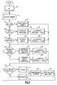
- FIG. 3 is a flowchart of main-line processing of a combined RFID and optical imager module the according to the present invention.
- FIGS. 4A and 4B are flowcharts of trigger command processing in a combined RFID and optical imager module according to the present invention.
- FIG. 5 is a schematic of an infusion pump according to the present invention.
- FIG. 6 is a flowchart of control processing in infusion pump according to the present invention.
- the present invention comprises an infusion pump including RFID and optical imaging capabilities.
- RFID and optical imaging capabilities are preferably provided via a combined RFID and optical imaging module that is interfaced with an infusion pump, or retrofit into an existing infusion pump, through a preexisting interface to provide RFID reading and optical imaging capabilities.
- Module 10 generally comprises a microcontroller 12 that interconnects a first submodule, such as an optical imager 14 , and a second submodule, such as an RFID unit 16 , to a single host interface 18 .
- module 10 is capable of interconnecting any variety of data capturing devices as submodules and providing host controllability, including optical imagers, RFID transceivers, lasers, scales, thermometers or temperature probes, etc., in any variety of combinations.
- Module 10 may be arranged on a single printed circuit board 22 and encased as a single unit or housing. Integration of imager 14 and RFID unit 16 through interface 18 allows for combining control of operation of both submodules, such as RFID reading and barcode, through module 10 , as will be explained in detail hereinafter.
- a first submodule of module 10 is illustrated as an optical imager 14 comprising an image engine 20 having image processing circuitry interconnected to microcontroller 12 for omni-directional optical scanning.
- Image engine 20 controls an image sensor 24 , such as a complementary metal oxide semiconductor (CMOS) image sensor, and is capable of capturing two-dimensional images of 1D linear barcodes, 2D stacked/matrix barcodes, standard optical character recognition (OCR) fonts, Reduced Space Symbology (RSS) barodes, and postal barcodes, as well as providing image captured images for use in a wide range of applications, such as image and shape recognition, signature capture, image capture, and non-standard optical character recognition.
- CMOS complementary metal oxide semiconductor
- Imager 14 may further include an illumination source 26 connected to engine 20 , such as one or more light emitting diodes (LEDs) of various wavelengths, to enhance illumination, operation, and image capture.
- module 10 may include red LEDs for general illumination and green LEDs for targeting.
- Imager 14 may comprise, but is not limited to, an IT4X10/80 SR/SF or IT5X10/80 series imager available from Hand Held Products, Inc. of Skaneateles Falls, N.Y. that is capable of scanning and decoding most standard barcodes including linear, stacked linear, matrix, OCR, and postal codes.
- the IT5X10/80 series imager is a CMOS-based decoded output engines that can read 2D codes, and has image capture capabilities sufficient for use with module 10 .
- Imager 14 obtains an optical image of the field of view and, using preprogrammed algorithms in image engine 20 , deciphers the context of the image to determine the presence of any decodable barcodes, linear codes, matrix codes, and the like.
- Image engine 20 may be programmed to perform other image processing algorithms on the image captured by imager 14 , such as shape recognition, match filtering, and other high-level processing techniques.
- a captured image may be processed by microprocessor 12 , albeit with a decreased level of performance due to the additional communication time needed to transfer images from image engine 20 to microprocessor 12 .
- Second submodule of module 10 may comprise an RFID unit 16 including an RFID transceiver 30 and associated RFID antenna 32 supporting standard RFID protocols, such as the TI Tag-it transponder protocol or ISO 15693.
- transceiver 30 operates at 13.56 MHz, and may comprise a S6700 Multi-Protocol Transceiver IC available from Texas Instruments of Dallas, Tex.
- RFID unit 16 may further include a speaker or LED (not shown) for audibly indicating a successful interrogation of an RFID tag.
- Antenna 32 is preferably a loop antenna of various sizes and turns implemented on a printed circuit board and connected to module 10 , or a wire loop installed antenna installed directly onto module 10 .
- Antenna 32 may be positioned remotely, thereby reducing the footprint of module 10 using an external connector, such as a MMCX coaxial connector.
- RFID transceiver 30 may be programmed to interrogate passive or active tags, process signals received from such tags (e.g., analog to digital conversion), and provide the information from the tags to microcontroller 12 for further processing or transmittal to a host computer via interface 18 .
- Host interface 18 comprises a host transceiver 34 and a host connector 36 for interconnection to a host device 38 .
- Interface 18 may comprise a conventional RS232 transceiver and associated 12 pin RJ style jack.
- an ADM202EARN available from Analog Devices, Inc. of Norwood, Mass. is a suitable RS-232/V.28 interface device having compliant levels of electromagnetic emissions and immunity.
- interface 18 may comprise other conventional buses, such as USB, IEEE 1394, 12C, SPI, or PCMCIA, or other connector styles, such as an FFC style to an embedded host or another module 10 .
- Interface 18 may also comprise a wireless transceiver in lieu of connector 36 for wireless communication to a host computer.
- SS-641010S-A-NF may serve as connector 36 for mating with a Stewart Connector 937-SP-361010-031 matching connector of a host device.
- Host interface 18 may also comprise a Molex MX52588 connector.
- host transceiver 34 is programmed with the applicable protocols for interfacing with a host computer, such as USB, Bluetooth(r), and IrDA protocols.
- Transceiver 34 may also be programmed to support both non-inverted signal sense and inverted signal sense.
- Microcontroller 12 comprises a conventional programmable microprocessor having on-chip peripherals, such as central processing unit, Flash EEPROM, RAM, asynchronous serial communications interface modules, serial peripheral interfaces, Inter-IC Buses, timer modules, pulse modulators with fault protection modules, pulse width modulators, analog-to-digital converters, and digital-to-analog converters. Additionally, the inclusion of a PLL circuit allows power consumption and performance to be adjusted to suit operational requirements. In addition to the I/O ports dedicated I/O port bits may be provided. Microcontroller 12 may further include an on-chip bandgap based voltage regulator that generates an internal digital supply voltage from an external supply range. Microcontroller 12 preferably comprises a Motorola MC9S12E128.
- microcontroller 12 which receives and interprets host commands, and then executes the appropriate functions by driving imager 14 and/or RFID unit 16 accordingly.
- the operation of imager 14 and RFID unit 16 may be triggered by serial commands sent to module 10 from a host device 38 , or by a hardware button communicating directly with connector 36 or through host device 38 .
- Microcontroller 12 may further be programmed to execute the functions otherwise performed by one or more of image engine 20 , RFID transceiver 30 , and host transceiver 34 , thereby reducing the amount of circuitry and hardware required by module 10 .
- module 10 When integrating imager 14 and RFID unit 16 , module 10 has three principle operational modes: image scanning using imager 14 , tag interrogation using RFID unit 16 , an interleaved mode that is a combination thereof, and a simultaneous mode.
- imaging-only mode module 10 will image and perform the applicable algorithms, such as barcode deciphering, until a barcode is detected or the device is un-triggered.
- RFID-only module 10 will interrogate until a tag is successfully read or module 10 is un-triggered.
- interleaved mode module 10 toggles between imaging and interrogation according to a predetermined timeout schedule.
- simultaneous mode module 10 causes simultaneous imaging and interrogation.
- module 10 may be programmed with timeouts to prevent hang-ups. As module 10 can receive, interpret, and execute host commands, these modes may be controlled by a user from host device 38 .
- Microcontroller 12 may direct RFID interrogation using RFID unit 16 in at least two modes.
- RFID unit 16 may operate in a free form mode that reads and writes data as a continuous stream, which is limited only by memory capacity. Once RFID unit 16 is triggered, depending on the mode, data is emitted from the serial port. Second, RFID unit 16 may operate in block mode, where a user may access individual blocks of information via commands sent through interface 18 and interpreted by microcontroller 12 .
- External control of module 10 is accomplished by a predefined protocol and set of serial host commands that are sent to module 10 from host device 38 .
- the host commands are received by microcontroller 12 , which executes the appropriate steps based on the content of the host command.
- microcontroller 12 may be programmed to recognize host commands that trigger the activation of imager 14 and/or RFID unit 16 .
- Host commands may also be defined to whether the data obtained from imager 14 and/or RFID unit 16 is stored locally in module 10 or passed through interface 18 to host device 38 .
- Host commands may also be provided that enable the various scanning or imaging modes available from imager 14 and RFID unit 16 , control the amount of time that imager 14 and RFID unit 16 will attempt scanning before timing out, direct the reading and writing of image and scan data, and select the location where the data is to be written.
- imager 14 and RFID unit 16 commands for opening and closing connections to image engine 20 and RFID transceiver 30 , as well as commands that return the status of the connection are useful.
- a host command received from host device 38 may trigger the capture of barcode or RFID data from imager 14 or RFID unit 16 .
- a timeout occurs or triggering is turned off via a second host command, and the appropriate feedback is provided to host device 38 .
- the host commands may be preprogrammed into microprocessor 12 and separately provided to host device 38 as a software package for controlling module 10 .
- software for editing host commands may be supplied to host device 38 to allow a user to edit, add, or delete commands and the corresponding functionality.
- FIG. 3 illustrates an embodiment of main-line host command processing in microprocessor 12 according to the present invention.
- the specific nomenclature used to define the various routines may be varied by the user or software developer provided that the appropriate functions are performed, and any number of routines and subroutines may be defined and executed in various orders to accomplish image and RFID reading and processing according to the present invention.
- microcontroller 12 runs a routine, referred to as GetHostCommand 42 , to check whether a host command has been received from host device 38 .
- microprocessor 12 Upon receipt of a host command, microprocessor 12 checks whether the command is an RFID control command, CMD_RFID 44 . If so, the command is processed by routine ProcessRFID_Command 46 .
- CMD_TRIGGER 48 If not, a check is performed to see whether the command is an trigger command, CMD_TRIGGER 48 . If the command is a trigger command, the appropriate instruction are processed to initiate triggering, InitTriggerProcessing 50 and a variable, referred to as CurrentlyTriggered 52 , is assigned the value of TRUE or FALSE depending on whether the selected device has already been triggered. If the command is not a trigger command, a check is performed to see whether the command is an untrigger command, CMD_UNTRIGGER 54 .
- UnTriggerImager 56 If the command is an untrigger command, the appropriate steps are taken to stop triggering, UnTriggerImager 56 , and a variable, CurrentlyTriggered 58 , is assigned the value of TRUE or FALSE depending on whether the selected device has already been triggered.
- microprocessor 12 checks to see whether a hardware trigger has been pressed 60 , the triggering processing is performed, InitTriggerProcessing 62 , and a variable, referred to as CurrentlyTriggered 64 , is assigned the value of TRUE or FALSE depending on whether the selected device has already been triggered. If a hardware trigger has not been pressed 60 , the appropriate instruction are processed to stop triggering, UnTriggerImager 66 , and a variable, referred to as CurrentlyTriggered 68 , is assigned the value of TRUE or FALSE depending on whether the selected device has already been triggered.
- microprocessor checks to see whether the CurrentlyTriggered variable is TRUE or FALSE 70 , and then calls function Trigger 72 or function UnTrigger 74 as appropriate. Data is then read from imager 14 and written to the host, ImagerReadAllHostWrite 76 , and host data that should be routed to imager 14 is written to it, FifoGetAllDataImagerWrite 78 .
- microcontroller 12 Upon receipt of a trigger command, microcontroller 12 first checks to see whether barcode only scanning 80 , RFID only scanning 82 , interleaved RFID and barcode scanning 84 , or simultaneous RFID and image scanning 86 has been previously selected. If bar code only scanning 80 has been selected for the first time 88 , and since InitTriggerProcessing 50 has been called, microcontroller 12 triggers imaging 90 . If an image is successfully captured and applicable information successfully extracted from the image 92 , such as barcode, microcontroller 12 assigns FALSE to the variable CurrentlyTriggered 94 .
- microcontroller 12 turns the RFID transmitter on 94 . If an RFID tag is successfully read 96 , an audible tone is sounded and microcontroller 12 sets variable CurrentlyTriggered to FALSE 98 . Microcontroller 12 turns transmitter off 100 . If interleaved RFID and barcode scanning 84 has been selected, microcontroller 12 toggles operation of imager 14 and RFID unit 16 using a timer 102 . If simultaneous RFID and image scanning 86 has been selected, microcontroller 12 checks to see whether the triggering is for the first time 104 and, if so, triggers the imager 106 . Transmission from the RFID unit 16 is also turned on 108 , and a nearby RFID tag is read 110 .
- variable CurrentlyTriggered is set to FALSE 112 .
- Imager 14 is also untriggered 114 and the transmitter is turned off 116 . If the image is successfully processed, e.g., a barcode is received 118 , and variable CurrentlyTriggered is set to FALSE 120 .
- an infusion pump 130 comprising a display screen 132 for visually presenting status or programming information and a keypad 134 or keyboard associated therewith for manual entry of data by medical personnel.
- Infusion pump 130 controls the delivery of fluid medication from an intravenous bag 136 through tubing 138 to a patient (not shown).
- Infusion pump 130 further comprises a microcontroller 140 for controlling the various operations and functionality of infusion pump 130 .
- Infusion pump 130 also comprises a combined RFID and imaging module 10 associated therewith.
- module 10 is provided within pump 130 and interconnected to microcontroller 140 via a connector 142 that mates with connector 36 of host interface 18 .
- microcontroller 140 of pump 130 acts as a host device, as explained above, and is programmed to provide host commands to module 10 , thereby controlling operation of optical imager 14 and RFID unit 16 .
- Module 10 is positioned within pump 130 so that imager 14 is flush with the housing of pump 130 , or so that all or a portion of imager 14 extends outwardly from pump 130 , such that object may be presented to imager 14 and one or images thereof may captured by imager 14 .
- Imager 14 may capture and decode barcode information contained on IV bag 136 , a badge 144 , or even a patient wristband 146 .
- module 10 also includes RFID unit 16 , information may be additionally stored on IV bag 136 , badge 144 , and patient wristband 146 for interrogation by RFID unit 16 .
- infusion pump 130 may be automatically provided with all of the information necessary to safely and securely verify that the proper medication is being given to the patient in the appropriate, prescribed dosages and rates.
- a sample control process 150 for pump 130 is illustrated in FIG. 6 . More particularly, infusion pump 130 is first activated 152 by a medical worker, such as by turning on infusion pump 130 . Next, the form of data retrieval is selected 154 , e.g., optical imaging/barcode and/or RFID. The format may be preprogrammed into microcontroller 140 , or manually selected by use of keypad 134 . After selection 154 , the appropriate host command is sent 156 to module 10 by microcontroller 140 . As described above, host commands controlling operation of module 10 may be supplied to a host device, such as infusion pump 130 , as software that is loadable onto microcontroller 140 . Next, data is acquired according to the host command 158 using imager 14 or RFID unit 16 .
- Successfully acquired data is then provided 160 by module 10 to infusion pump 130 via host interface 18 to microcontroller 140 using the appropriate protocols. If any additional data is to be automatically provided to infusion pump 130 , steps 154 - 160 may be repeated for each object from which data is to be acquired. Microcontroller 140 then verifies that delivery is proper 162 by considering the data acquired by module 10 , and infusion pump 130 is enabled for delivery of medication to the patient.
- Verification of delivery 162 encompasses any number of checks.
- microcontroller 140 may receive information about the particular medicine to be dispensed from bag 136 , about the individual who is authorizing the delivery of the medicine from badge 144 , and about the patient who will be receiving the medication from wristband 146 , whether by capturing optical images of identification objects containing indicia, such as barcodes, or data stored within identification objects, such as RFID tags.
- Microcontroller 140 may then retrieve the patient's electronic medical records from the hospital's electronic medical records database, whether copied and stored locally or accessed remotely through a hospital-wide network, and compare the stored information with the acquired information to ensure that the IV medications were actually ordered for the patient, and to confirm when the patient is scheduled to receive the medication.
- Microcontroller 140 can also verify the identity of the medical worker who is activating the infusion pump to ensure that the person is authorized to dispense the particular medication. Microcontroller 140 can further cross-check the prescribed dosage for the particular medication against stored medical records containing the proper dosages and infusion rates for particular medications. Only after some or all of these checks are performed will infusion pump 130 be enabled 164 to deliver medicine to the patient.
Abstract
Description
Claims (10)
Priority Applications (1)
| Application Number | Priority Date | Filing Date | Title |
|---|---|---|---|
| US11/279,275 US7743975B2 (en) | 2006-03-09 | 2006-04-11 | Infusion pump having radiofrequency identification and optical imaging capabilities |
Applications Claiming Priority (2)
| Application Number | Priority Date | Filing Date | Title |
|---|---|---|---|
| US11/308,170 US7766235B2 (en) | 2006-03-09 | 2006-03-09 | Combined radio frequency identification and optical imaging module |
| US11/279,275 US7743975B2 (en) | 2006-03-09 | 2006-04-11 | Infusion pump having radiofrequency identification and optical imaging capabilities |
Related Parent Applications (1)
| Application Number | Title | Priority Date | Filing Date |
|---|---|---|---|
| US11/308,170 Continuation-In-Part US7766235B2 (en) | 2006-03-09 | 2006-03-09 | Combined radio frequency identification and optical imaging module |
Publications (2)
| Publication Number | Publication Date |
|---|---|
| US20070210157A1 US20070210157A1 (en) | 2007-09-13 |
| US7743975B2 true US7743975B2 (en) | 2010-06-29 |
Family
ID=46325383
Family Applications (1)
| Application Number | Title | Priority Date | Filing Date |
|---|---|---|---|
| US11/279,275 Active 2026-08-11 US7743975B2 (en) | 2006-03-09 | 2006-04-11 | Infusion pump having radiofrequency identification and optical imaging capabilities |
Country Status (1)
| Country | Link |
|---|---|
| US (1) | US7743975B2 (en) |
Cited By (30)
| Publication number | Priority date | Publication date | Assignee | Title |
|---|---|---|---|---|
| US20080045930A1 (en) * | 2006-08-21 | 2008-02-21 | Ronald Makin | System and Method of Drug Identification Through Radio Frequency Identification (RFID) |
| US20090045261A1 (en) * | 2007-08-14 | 2009-02-19 | Jadak, Llc | Method For Providing User Feedback In An Autoidentification System |
| CN102122364A (en) * | 2011-02-22 | 2011-07-13 | 电子科技大学 | RFID wireless communication-based transfusion monitoring system |
| US8105269B2 (en) | 2008-10-24 | 2012-01-31 | Baxter International Inc. | In situ tubing measurements for infusion pumps |
| US8137083B2 (en) | 2009-03-11 | 2012-03-20 | Baxter International Inc. | Infusion pump actuators, system and method for controlling medical fluid flowrate |
| US8382447B2 (en) | 2009-12-31 | 2013-02-26 | Baxter International, Inc. | Shuttle pump with controlled geometry |
| US8567235B2 (en) | 2010-06-29 | 2013-10-29 | Baxter International Inc. | Tube measurement technique using linear actuator and pressure sensor |
| US9295778B2 (en) | 2011-12-21 | 2016-03-29 | Deka Products Limited Partnership | Syringe pump |
| US9384397B2 (en) | 2013-08-22 | 2016-07-05 | Ut-Battelle, Llc | Model for mapping settlements |
| US9489785B2 (en) | 2013-03-14 | 2016-11-08 | Covidien Lp | RFID secure authentication |
| US9675756B2 (en) | 2011-12-21 | 2017-06-13 | Deka Products Limited Partnership | Apparatus for infusing fluid |
| US9677555B2 (en) | 2011-12-21 | 2017-06-13 | Deka Products Limited Partnership | System, method, and apparatus for infusing fluid |
| US9744300B2 (en) | 2011-12-21 | 2017-08-29 | Deka Products Limited Partnership | Syringe pump and related method |
| US9789247B2 (en) | 2011-12-21 | 2017-10-17 | Deka Products Limited Partnership | Syringe pump, and related method and system |
| US10130382B2 (en) | 2014-03-27 | 2018-11-20 | Medtronic Xomed, Inc. | Powered surgical handpiece having a surgical tool with an RFID tag |
| US10242159B2 (en) | 2010-01-22 | 2019-03-26 | Deka Products Limited Partnership | System and apparatus for electronic patient care |
| US10265463B2 (en) | 2014-09-18 | 2019-04-23 | Deka Products Limited Partnership | Apparatus and method for infusing fluid through a tube by appropriately heating the tube |
| US10391241B2 (en) | 2010-01-22 | 2019-08-27 | Deka Products Limited Partnership | Syringe pump having a pressure sensor assembly |
| US10453157B2 (en) | 2010-01-22 | 2019-10-22 | Deka Products Limited Partnership | System, method, and apparatus for electronic patient care |
| US10722645B2 (en) | 2011-12-21 | 2020-07-28 | Deka Products Limited Partnership | Syringe pump, and related method and system |
| US10872685B2 (en) | 2010-01-22 | 2020-12-22 | Deka Products Limited Partnership | Electronic patient monitoring system |
| US10911515B2 (en) | 2012-05-24 | 2021-02-02 | Deka Products Limited Partnership | System, method, and apparatus for electronic patient care |
| US11016754B2 (en) | 2017-12-28 | 2021-05-25 | Elatec GmbH | Infusion pumps with RFID user identification |
| US11164672B2 (en) | 2010-01-22 | 2021-11-02 | Deka Products Limited Partnership | System and apparatus for electronic patient care |
| US11210611B2 (en) | 2011-12-21 | 2021-12-28 | Deka Products Limited Partnership | System, method, and apparatus for electronic patient care |
| US11217340B2 (en) | 2011-12-21 | 2022-01-04 | Deka Products Limited Partnership | Syringe pump having a pressure sensor assembly |
| US11244745B2 (en) | 2010-01-22 | 2022-02-08 | Deka Products Limited Partnership | Computer-implemented method, system, and apparatus for electronic patient care |
| US11295846B2 (en) | 2011-12-21 | 2022-04-05 | Deka Products Limited Partnership | System, method, and apparatus for infusing fluid |
| US11707615B2 (en) | 2018-08-16 | 2023-07-25 | Deka Products Limited Partnership | Medical pump |
| US11881307B2 (en) | 2012-05-24 | 2024-01-23 | Deka Products Limited Partnership | System, method, and apparatus for electronic patient care |
Families Citing this family (23)
| Publication number | Priority date | Publication date | Assignee | Title |
|---|---|---|---|---|
| US11087873B2 (en) | 2000-05-18 | 2021-08-10 | Carefusion 303, Inc. | Context-aware healthcare notification system |
| US9741001B2 (en) | 2000-05-18 | 2017-08-22 | Carefusion 303, Inc. | Predictive medication safety |
| US10062457B2 (en) | 2012-07-26 | 2018-08-28 | Carefusion 303, Inc. | Predictive notifications for adverse patient events |
| US7860583B2 (en) | 2004-08-25 | 2010-12-28 | Carefusion 303, Inc. | System and method for dynamically adjusting patient therapy |
| WO2001088828A2 (en) | 2000-05-18 | 2001-11-22 | Alaris Medical Systems, Inc. | Distributed remote asset and medication management drug delivery system |
| US10353856B2 (en) | 2011-03-17 | 2019-07-16 | Carefusion 303, Inc. | Scalable communication system |
| US9427520B2 (en) | 2005-02-11 | 2016-08-30 | Carefusion 303, Inc. | Management of pending medication orders |
| US8034019B2 (en) * | 2007-04-10 | 2011-10-11 | Amrita Vishwa Vidyapeetham | Dual microcontroller-based liquid infusion system |
| US8162219B2 (en) * | 2008-01-09 | 2012-04-24 | Jadak Llc | System and method for logo identification and verification |
| US10441710B2 (en) * | 2009-02-09 | 2019-10-15 | Baxter International Inc. | Infusion pump and method to prevent titration errors in infusion therapies |
| US8172798B2 (en) * | 2009-05-12 | 2012-05-08 | Sigma International General Medical Apparatus LLC | System and method for managing infusion therapies |
| TWI633902B (en) * | 2010-03-22 | 2018-09-01 | 賽諾菲阿凡提斯德意志有限公司 | Device, method, system and computer program for determining information related to a medical device |
| US9190010B2 (en) * | 2011-01-10 | 2015-11-17 | CareFushion 303, Inc. | Displaying visual elements on a medical device |
| CN102609544A (en) * | 2012-03-12 | 2012-07-25 | 腾讯科技(深圳)有限公司 | Method and device for obtaining information as well as mobile terminal |
| DK2945668T3 (en) | 2013-01-15 | 2018-09-03 | Sanofi Aventis Deutschland | ASSEMBLY ASSEMBLY FOR A MEDICAL INJECTION DEVICE FOR GENERATION OF USE REPORTS ON THE USE OF THE DIGITAL IMAGE INJECTION DEVICE |
| US11182728B2 (en) | 2013-01-30 | 2021-11-23 | Carefusion 303, Inc. | Medication workflow management |
| US10430554B2 (en) | 2013-05-23 | 2019-10-01 | Carefusion 303, Inc. | Medication preparation queue |
| CN105074766A (en) | 2013-03-13 | 2015-11-18 | 康尔福盛303公司 | Predictive medication safety |
| EP2973366B1 (en) | 2013-03-13 | 2020-08-19 | Carefusion 303 Inc. | Patient-specific medication management system |
| CN105188805B (en) * | 2013-03-13 | 2018-12-25 | 康尔福盛303公司 | Injection is single and conveys consistency |
| CN109045407A (en) * | 2018-08-31 | 2018-12-21 | 四川省肿瘤医院 | A kind of real-time transfusion monitoring system of gravity type stabilization based on ZigBee-network |
| WO2020227470A1 (en) * | 2019-05-07 | 2020-11-12 | University Of South Carolina | Syringe pump system and method for operating the same |
| WO2021211735A1 (en) * | 2020-04-15 | 2021-10-21 | Carefusion 303, Inc. | Infusion pump administration system |
Citations (16)
| Publication number | Priority date | Publication date | Assignee | Title |
|---|---|---|---|---|
| US6127928A (en) * | 1998-02-10 | 2000-10-03 | E-Tag Systems, Inc. | Method and apparatus for locating and tracking documents and other objects |
| US20020038392A1 (en) * | 1999-10-22 | 2002-03-28 | Carlos De La Huerga | Method and apparatus for controlling an infusion pump or the like |
| US20020063622A1 (en) * | 2000-11-29 | 2002-05-30 | Ludwig Kipp | Method and system for communicating with and tracking RFID transponders |
| US6501382B1 (en) | 2001-06-11 | 2002-12-31 | Timken Company | Bearing with data storage device |
| US20030095525A1 (en) | 2000-04-13 | 2003-05-22 | Daniel Lavin | Navigation control unit for a wireless computer resource access device, such as a wireless web content access device |
| US20030135388A1 (en) * | 2002-01-11 | 2003-07-17 | James Martucci | Medication delivery system |
| US20030132298A1 (en) | 1996-09-05 | 2003-07-17 | Jerome Swartz | Consumer interactive shopping system |
| US20040118920A1 (en) | 2002-12-18 | 2004-06-24 | Duanfeng He | System and method for verifying optical character recognition of optical code reads |
| US20040177032A1 (en) | 2003-03-03 | 2004-09-09 | Bradley A. (Tony) W. | System, method, and apparatus for identifying and authenticating the presence of high value assets at remote locations |
| US20050144044A1 (en) | 2003-09-29 | 2005-06-30 | Samsung Electronics Co., Ltd. | System and apparatus for efficiently utilizing network capacity in a healthcare setting |
| US20050150959A1 (en) | 2004-01-09 | 2005-07-14 | John Izzo | Optical reader |
| US20050156040A1 (en) | 2004-01-16 | 2005-07-21 | Young David H. | Radio frequency identification device with movable antenna |
| US20050184160A1 (en) | 2004-02-20 | 2005-08-25 | Jay Steinmetz | Combination handheld sealer/wireless scanning/imaging device |
| US20050203941A1 (en) | 2004-01-14 | 2005-09-15 | Polarine Christine D.A. | Monitoring device used for producing compositions |
| US20050282603A1 (en) | 2004-06-18 | 2005-12-22 | Igt | Gaming machine user interface |
| US20060023930A1 (en) | 2004-07-29 | 2006-02-02 | Mehul Patel | Device for digitizing and processing checks in accordance with the Check 21 Act and for reading and decoding optical codes |
-
2006
- 2006-04-11 US US11/279,275 patent/US7743975B2/en active Active
Patent Citations (17)
| Publication number | Priority date | Publication date | Assignee | Title |
|---|---|---|---|---|
| US20030132298A1 (en) | 1996-09-05 | 2003-07-17 | Jerome Swartz | Consumer interactive shopping system |
| US6127928A (en) * | 1998-02-10 | 2000-10-03 | E-Tag Systems, Inc. | Method and apparatus for locating and tracking documents and other objects |
| US20020038392A1 (en) * | 1999-10-22 | 2002-03-28 | Carlos De La Huerga | Method and apparatus for controlling an infusion pump or the like |
| US20030095525A1 (en) | 2000-04-13 | 2003-05-22 | Daniel Lavin | Navigation control unit for a wireless computer resource access device, such as a wireless web content access device |
| US20020063622A1 (en) * | 2000-11-29 | 2002-05-30 | Ludwig Kipp | Method and system for communicating with and tracking RFID transponders |
| US6501382B1 (en) | 2001-06-11 | 2002-12-31 | Timken Company | Bearing with data storage device |
| US20030135388A1 (en) * | 2002-01-11 | 2003-07-17 | James Martucci | Medication delivery system |
| WO2004059563A1 (en) | 2002-12-18 | 2004-07-15 | Symbol Technologies, Inc. | System and method for verifying optical code reads and rfid reads |
| US20040118920A1 (en) | 2002-12-18 | 2004-06-24 | Duanfeng He | System and method for verifying optical character recognition of optical code reads |
| US20040177032A1 (en) | 2003-03-03 | 2004-09-09 | Bradley A. (Tony) W. | System, method, and apparatus for identifying and authenticating the presence of high value assets at remote locations |
| US20050144044A1 (en) | 2003-09-29 | 2005-06-30 | Samsung Electronics Co., Ltd. | System and apparatus for efficiently utilizing network capacity in a healthcare setting |
| US20050150959A1 (en) | 2004-01-09 | 2005-07-14 | John Izzo | Optical reader |
| US20050203941A1 (en) | 2004-01-14 | 2005-09-15 | Polarine Christine D.A. | Monitoring device used for producing compositions |
| US20050156040A1 (en) | 2004-01-16 | 2005-07-21 | Young David H. | Radio frequency identification device with movable antenna |
| US20050184160A1 (en) | 2004-02-20 | 2005-08-25 | Jay Steinmetz | Combination handheld sealer/wireless scanning/imaging device |
| US20050282603A1 (en) | 2004-06-18 | 2005-12-22 | Igt | Gaming machine user interface |
| US20060023930A1 (en) | 2004-07-29 | 2006-02-02 | Mehul Patel | Device for digitizing and processing checks in accordance with the Check 21 Act and for reading and decoding optical codes |
Cited By (59)
| Publication number | Priority date | Publication date | Assignee | Title |
|---|---|---|---|---|
| US20080045930A1 (en) * | 2006-08-21 | 2008-02-21 | Ronald Makin | System and Method of Drug Identification Through Radio Frequency Identification (RFID) |
| US20090045261A1 (en) * | 2007-08-14 | 2009-02-19 | Jadak, Llc | Method For Providing User Feedback In An Autoidentification System |
| US7942329B2 (en) * | 2007-08-14 | 2011-05-17 | Jadak, Llc | Method for providing user feedback in an autoidentification system |
| US8105269B2 (en) | 2008-10-24 | 2012-01-31 | Baxter International Inc. | In situ tubing measurements for infusion pumps |
| US8496613B2 (en) | 2008-10-24 | 2013-07-30 | Baxter International Inc. | In situ tubing measurements for infusion pumps |
| US8137083B2 (en) | 2009-03-11 | 2012-03-20 | Baxter International Inc. | Infusion pump actuators, system and method for controlling medical fluid flowrate |
| US8382447B2 (en) | 2009-12-31 | 2013-02-26 | Baxter International, Inc. | Shuttle pump with controlled geometry |
| US11424029B2 (en) | 2010-01-22 | 2022-08-23 | Deka Products Limited Partnership | System, method and apparatus for electronic patient care |
| US11810653B2 (en) | 2010-01-22 | 2023-11-07 | Deka Products Limited Partnership | Computer-implemented method, system, and apparatus for electronic patient care |
| US11776671B2 (en) | 2010-01-22 | 2023-10-03 | Deka Products Limited Partnership | Electronic patient monitoring system |
| US11524107B2 (en) | 2010-01-22 | 2022-12-13 | Deka Products Limited Partnership | System, method, and apparatus for electronic patient care |
| US10242159B2 (en) | 2010-01-22 | 2019-03-26 | Deka Products Limited Partnership | System and apparatus for electronic patient care |
| US11244745B2 (en) | 2010-01-22 | 2022-02-08 | Deka Products Limited Partnership | Computer-implemented method, system, and apparatus for electronic patient care |
| US11164672B2 (en) | 2010-01-22 | 2021-11-02 | Deka Products Limited Partnership | System and apparatus for electronic patient care |
| US10872685B2 (en) | 2010-01-22 | 2020-12-22 | Deka Products Limited Partnership | Electronic patient monitoring system |
| US10453157B2 (en) | 2010-01-22 | 2019-10-22 | Deka Products Limited Partnership | System, method, and apparatus for electronic patient care |
| US10391241B2 (en) | 2010-01-22 | 2019-08-27 | Deka Products Limited Partnership | Syringe pump having a pressure sensor assembly |
| US8567235B2 (en) | 2010-06-29 | 2013-10-29 | Baxter International Inc. | Tube measurement technique using linear actuator and pressure sensor |
| CN102122364A (en) * | 2011-02-22 | 2011-07-13 | 电子科技大学 | RFID wireless communication-based transfusion monitoring system |
| US10561787B2 (en) | 2011-12-21 | 2020-02-18 | Deka Products Limited Partnership | Syringe pump and related method |
| US9677555B2 (en) | 2011-12-21 | 2017-06-13 | Deka Products Limited Partnership | System, method, and apparatus for infusing fluid |
| US10245374B2 (en) | 2011-12-21 | 2019-04-02 | Deka Products Limited Partnership | Syringe pump |
| US11826543B2 (en) | 2011-12-21 | 2023-11-28 | Deka Products Limited Partneship | Syringe pump, and related method and system |
| US10288057B2 (en) | 2011-12-21 | 2019-05-14 | Deka Products Limited Partnership | Peristaltic pump |
| US9295778B2 (en) | 2011-12-21 | 2016-03-29 | Deka Products Limited Partnership | Syringe pump |
| US10316834B2 (en) | 2011-12-21 | 2019-06-11 | Deka Products Limited Partnership | Peristaltic pump |
| US10202970B2 (en) | 2011-12-21 | 2019-02-12 | Deka Products Limited Partnership | System, method, and apparatus for infusing fluid |
| US11779703B2 (en) | 2011-12-21 | 2023-10-10 | Deka Products Limited Partnership | Apparatus for infusing fluid |
| US9675756B2 (en) | 2011-12-21 | 2017-06-13 | Deka Products Limited Partnership | Apparatus for infusing fluid |
| US10722645B2 (en) | 2011-12-21 | 2020-07-28 | Deka Products Limited Partnership | Syringe pump, and related method and system |
| US10753353B2 (en) | 2011-12-21 | 2020-08-25 | Deka Products Limited Partnership | Peristaltic pump |
| US10857293B2 (en) | 2011-12-21 | 2020-12-08 | Deka Products Limited Partnership | Apparatus for infusing fluid |
| US11756662B2 (en) | 2011-12-21 | 2023-09-12 | Deka Products Limited Partnership | Peristaltic pump |
| US11705233B2 (en) | 2011-12-21 | 2023-07-18 | Deka Products Limited Partnership | Peristaltic pump |
| US11664106B2 (en) | 2011-12-21 | 2023-05-30 | Deka Products Limited Partnership | Syringe pump |
| US11615886B2 (en) | 2011-12-21 | 2023-03-28 | Deka Products Limited Partnership | Syringe pump and related method |
| US11024409B2 (en) | 2011-12-21 | 2021-06-01 | Deka Products Limited Partnership | Peristaltic pump |
| US11129933B2 (en) | 2011-12-21 | 2021-09-28 | Deka Products Limited Partnership | Syringe pump, and related method and system |
| US10202971B2 (en) | 2011-12-21 | 2019-02-12 | Deka Products Limited Partnership | Peristaltic pump |
| US11210611B2 (en) | 2011-12-21 | 2021-12-28 | Deka Products Limited Partnership | System, method, and apparatus for electronic patient care |
| US11217340B2 (en) | 2011-12-21 | 2022-01-04 | Deka Products Limited Partnership | Syringe pump having a pressure sensor assembly |
| US9789247B2 (en) | 2011-12-21 | 2017-10-17 | Deka Products Limited Partnership | Syringe pump, and related method and system |
| US11295846B2 (en) | 2011-12-21 | 2022-04-05 | Deka Products Limited Partnership | System, method, and apparatus for infusing fluid |
| US11348674B2 (en) | 2011-12-21 | 2022-05-31 | Deka Products Limited Partnership | Peristaltic pump |
| US11373747B2 (en) | 2011-12-21 | 2022-06-28 | Deka Products Limited Partnership | Peristaltic pump |
| US9744300B2 (en) | 2011-12-21 | 2017-08-29 | Deka Products Limited Partnership | Syringe pump and related method |
| US11511038B2 (en) | 2011-12-21 | 2022-11-29 | Deka Products Limited Partnership | Apparatus for infusing fluid |
| US10911515B2 (en) | 2012-05-24 | 2021-02-02 | Deka Products Limited Partnership | System, method, and apparatus for electronic patient care |
| US11881307B2 (en) | 2012-05-24 | 2024-01-23 | Deka Products Limited Partnership | System, method, and apparatus for electronic patient care |
| US9489785B2 (en) | 2013-03-14 | 2016-11-08 | Covidien Lp | RFID secure authentication |
| US9774455B2 (en) | 2013-03-14 | 2017-09-26 | Covidien Lp | RFID secure authentication |
| US10298403B2 (en) | 2013-03-14 | 2019-05-21 | Covidien Lp | RFID secure authentication |
| US9384397B2 (en) | 2013-08-22 | 2016-07-05 | Ut-Battelle, Llc | Model for mapping settlements |
| US10987121B2 (en) | 2014-03-27 | 2021-04-27 | Medtronic Xomed, Inc. | Powered surgical handpiece having a surgical tool with an RFID tag |
| US10130382B2 (en) | 2014-03-27 | 2018-11-20 | Medtronic Xomed, Inc. | Powered surgical handpiece having a surgical tool with an RFID tag |
| US11672903B2 (en) | 2014-09-18 | 2023-06-13 | Deka Products Limited Partnership | Apparatus and method for infusing fluid through a tube by appropriately heating the tube |
| US10265463B2 (en) | 2014-09-18 | 2019-04-23 | Deka Products Limited Partnership | Apparatus and method for infusing fluid through a tube by appropriately heating the tube |
| US11016754B2 (en) | 2017-12-28 | 2021-05-25 | Elatec GmbH | Infusion pumps with RFID user identification |
| US11707615B2 (en) | 2018-08-16 | 2023-07-25 | Deka Products Limited Partnership | Medical pump |
Also Published As
| Publication number | Publication date |
|---|---|
| US20070210157A1 (en) | 2007-09-13 |
Similar Documents
| Publication | Publication Date | Title |
|---|---|---|
| US7743975B2 (en) | Infusion pump having radiofrequency identification and optical imaging capabilities | |
| CA2596701C (en) | Identification system and method for medication management | |
| US7236936B2 (en) | Security infusion pump with bar code reader | |
| AU2003291138B2 (en) | Medication management system | |
| US7614554B2 (en) | Electrosurgical device having RFID and optical imaging capabilities | |
| US7942329B2 (en) | Method for providing user feedback in an autoidentification system | |
| US7631809B2 (en) | Antenna for combined RFID optical imager | |
| EP1944709A1 (en) | Identification system and method for medication management | |
| NZ560952A (en) | Assigning a medication delivery device to a medication after barcode labels are read | |
| US7766235B2 (en) | Combined radio frequency identification and optical imaging module |
Legal Events
| Date | Code | Title | Description |
|---|---|---|---|
| AS | Assignment |
Owner name: JADAK TECHNOLOGIES, NEW YORK Free format text: ASSIGNMENT OF ASSIGNORS INTEREST;ASSIGNOR:MILLER, DAVID PAUL;REEL/FRAME:017465/0113 Effective date: 20060407 Owner name: JADAK TECHNOLOGIES,NEW YORK Free format text: ASSIGNMENT OF ASSIGNORS INTEREST;ASSIGNOR:MILLER, DAVID PAUL;REEL/FRAME:017465/0113 Effective date: 20060407 |
|
| AS | Assignment |
Owner name: JADAK TECHNOLOGIES, INC., NEW YORK Free format text: CORRECTIVE ASSIGNMENT TO CORRECT THE ASSIGNEE NAME PREVIOUSLY RECORDED ON REEL 017485 FRAME 0113;ASSIGNOR:MILLER, DAVID PAUL;REEL/FRAME:017919/0754 Effective date: 20060407 Owner name: JADAK TECHNOLOGIES, INC.,NEW YORK Free format text: CORRECTIVE ASSIGNMENT TO CORRECT THE ASSIGNEE NAME PREVIOUSLY RECORDED ON REEL 017485 FRAME 0113. ASSIGNOR(S) HEREBY CONFIRMS THE ASSIGNMENT;ASSIGNOR:MILLER, DAVID PAUL;REEL/FRAME:017919/0754 Effective date: 20060407 |
|
| AS | Assignment |
Owner name: JADAK, LLC,NEW YORK Free format text: ASSIGNMENT OF ASSIGNORS INTEREST;ASSIGNOR:JADAK TECHNOLOGIES, INC.;REEL/FRAME:019030/0897 Effective date: 20070319 Owner name: JADAK, LLC, NEW YORK Free format text: ASSIGNMENT OF ASSIGNORS INTEREST;ASSIGNOR:JADAK TECHNOLOGIES, INC.;REEL/FRAME:019030/0897 Effective date: 20070319 |
|
| STCF | Information on status: patent grant |
Free format text: PATENTED CASE |
|
| FPAY | Fee payment |
Year of fee payment: 4 |
|
| AS | Assignment |
Owner name: BANK OF AMERICA, N.A., ILLINOIS Free format text: SECURITY INTEREST;ASSIGNOR:JADAK, LLC;REEL/FRAME:032626/0987 Effective date: 20140404 |
|
| MAFP | Maintenance fee payment |
Free format text: PAYMENT OF MAINTENANCE FEE, 8TH YR, SMALL ENTITY (ORIGINAL EVENT CODE: M2552) Year of fee payment: 8 |
|
| AS | Assignment |
Owner name: NOVANTA CORPORATION, MASSACHUSETTS Free format text: ASSIGNMENT OF ASSIGNORS INTEREST;ASSIGNOR:JADAK, LLC;REEL/FRAME:044588/0785 Effective date: 20171229 |
|
| MAFP | Maintenance fee payment |
Free format text: PAYMENT OF MAINTENANCE FEE, 12TH YR, SMALL ENTITY (ORIGINAL EVENT CODE: M2553); ENTITY STATUS OF PATENT OWNER: SMALL ENTITY Year of fee payment: 12 |