US7738087B1 - Stereoscopic targeting, tracking and navigation device, system and method - Google Patents
Stereoscopic targeting, tracking and navigation device, system and method Download PDFInfo
- Publication number
- US7738087B1 US7738087B1 US12/245,756 US24575608A US7738087B1 US 7738087 B1 US7738087 B1 US 7738087B1 US 24575608 A US24575608 A US 24575608A US 7738087 B1 US7738087 B1 US 7738087B1
- Authority
- US
- United States
- Prior art keywords
- sensor
- target
- azimuth
- sensors
- beacon
- Prior art date
- Legal status (The legal status is an assumption and is not a legal conclusion. Google has not performed a legal analysis and makes no representation as to the accuracy of the status listed.)
- Expired - Fee Related
Links
Images


Classifications
-
- G—PHYSICS
- G01—MEASURING; TESTING
- G01C—MEASURING DISTANCES, LEVELS OR BEARINGS; SURVEYING; NAVIGATION; GYROSCOPIC INSTRUMENTS; PHOTOGRAMMETRY OR VIDEOGRAMMETRY
- G01C11/00—Photogrammetry or videogrammetry, e.g. stereogrammetry; Photographic surveying
- G01C11/04—Interpretation of pictures
- G01C11/30—Interpretation of pictures by triangulation
-
- G—PHYSICS
- G01—MEASURING; TESTING
- G01S—RADIO DIRECTION-FINDING; RADIO NAVIGATION; DETERMINING DISTANCE OR VELOCITY BY USE OF RADIO WAVES; LOCATING OR PRESENCE-DETECTING BY USE OF THE REFLECTION OR RERADIATION OF RADIO WAVES; ANALOGOUS ARRANGEMENTS USING OTHER WAVES
- G01S5/00—Position-fixing by co-ordinating two or more direction or position line determinations; Position-fixing by co-ordinating two or more distance determinations
- G01S5/16—Position-fixing by co-ordinating two or more direction or position line determinations; Position-fixing by co-ordinating two or more distance determinations using electromagnetic waves other than radio waves
Definitions
- the present invention relates to targeting and navigation systems and, more particularly, to triangulation-type targeting and navigating.
- U.S. Pat. No. 3,937,951 uses two sensors to determine the location of a lightning event. This device is only capable of determining the average location of the lightning event.
- a measurement system with at least 2 sensors to identify precise locations of remote objects.
- the sensors detect electro-magnetic radiation which is either emitted from or reflected off of the object, and measures the elevation and azimuth angles to the target. Given a known distance between the 2 sensors, the system is then able to calculate the exact location of the object using a modified type of triangulation. In the case of moving targets, this data is used to determine target trajectory, origin and destination. In the case of stationary targets, the data is used to determine the exact location of the target for mapping and for navigation to or around the stationary target.
- a sensor system for tracking and navigation comprising: two sensors, each sensor comprising a two-dimensional plurality of discrete detection pixels; for each sensor, computerized data associating each detection pixel thereof with a predetermined azimuth angle and a predetermined elevation angle; computerized means for automatically determining azimuth angles and elevation angles of a target or beacon simultaneously detected by each of the sensors, for each of the sensors, based on the computerized data; and computerized means for calculating a three-dimensional position of the target or beacon, based on the azimuth angles and the elevation angles of the target or beacon for each of the sensors, and based on a known distance and relative orientation between each of the sensors.
- a computerized device and related method for use in connection with a sensor system for tracking and navigation comprising computerized input, storage and processing means for: receiving input data specifying a detection pixel of a sensor which has detected a target or beacon; storing computerized data associating each detection pixel with a predetermined azimuth angle and a predetermined elevation angle; and determining an azimuth angle and an elevation angle of the detected target or beacon from the input data in association with the stored computerized data.
- a method and related apparatus for calibrating a sensor for tracking and navigation comprising the steps of: striking the sensor with calibration electromagnetic radiation originating at known azimuth and elevation angles; determining which detection pixels of the sensor are activated by the calibration electromagnetic radiation; and associating the activated detection pixels with the known azimuth and elevation angles.
- a sensor system and related method for tracking and navigation comprising: a sensor comprising a two-dimensional plurality of discrete detection pixels; and computerized data associating each the detection pixel with a predetermined azimuth angle and a predetermined elevation angle; wherein: when a target or beacon is detected by a given pixel of the sensor, an azimuth angle and an elevation angle of the target or beacon is automatically determined from the computerized data.
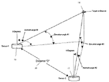
- FIG. 1 is a side view of a simplified two-sensor arrangement with key measurement parameters.
- FIG. 2 is a cross sectional view of a two-sensor system.
- FIG. 3 is a perspective top view of an image sensor, preferably an optical sensor and more preferably a charged coupled device (CCD). This Figure also shows a possible memory mapping for the CCD.
- CCD charged coupled device
- FIG. 4 is a perspective view of an advanced image sensor with self-calibration via, e.g., laser and/or GPS.
- FIG. 5 is a perspective top view of a 4 sensor array in an alternative preferred embodiment.
- FIG. 6 is a rear view of a situation in which a target is directly over the zenith of the left sensor (sensor 1 ).
- FIG. 7 is a perspective top view of a target in view of a two sensor array.
- FIG. 8 is an orthogonal view of a right triangle formed by elevation angle E 2 and hypotenuse D 2 .
- FIG. 9 is a perspective top view of a system memory configuration which is very resource intensive, and thus not preferred and illustrative only.
- FIG. 10 is a perspective view, for example not limitation, of a possible system memory configuration.
- FIG. 1 is a perspective side view of a simplified sensor arrangement with key measurement parameters.
- a minimum of two sensors left (first) sensor 10 , right (second) sensor 12 ) are located in the same horizontal plane. Both sensors are aligned such that their 0 degree azimuth directions (i.e. north) are congruent and they are each leveled with the sensing lens facing up to the sky.
- the distance between the sensors must be established. This may be done physically with, e.g., compasses, bubble levels, and sighting eyepieces.
- this process may also be simplified using a preferred sensor to be later described which comprises additional electronics to automate this process and allow for significant variation from this basic configuration.
- the upshot is that the distance and relative orientation between each of the sensors needs to be known before the system can be effectively utilized for tracking or navigation.
- the sensors 10 and 12 are used to detect electromagnetic radiation from a moving target or beacon 14 located in the sky or on the ground. For use at night, one may employ infra-red or ultraviolet sensors.
- each sensor in the system is able to independently determine the azimuth angle and the elevation angle to the target or beacon 14 . Given the initial conditions of azimuth angles A 1 , A 2 , elevation angles E 1 , E 2 , and Distance “D” 40 the system processor is able to calculate the exact location of the target using the following trigonometric calculations with right sensor 12 defined as the system origin.
- FIG. 8 is an orthogonal view of the right triangle formed by elevation E 2 and hypotenuse D 2 52 .
- the data may be represented in the X-Y-Z location coordinates derived above, or in any other suitable coordinate system.
- the data may also be converted into GPS data if system was initially calibrated with GPS.
- the trajectory data points obtained can be utilized in a number of ways.
- This system could be used directly for surveying.
- this system could be used to measure distance to the top of a mountain or building if, for example, one points a laser on the mountain or building, and then detects the X-Y-Z coordinate of the laser point.
- a series of coordinates with time separation data may be input to a computerized device with suitable hardware, software and storage for calculating a “best fit” trajectory in order to reverse-interpolate the origin of the target.
- series of coordinates with time separation data may be input to a computerized device with suitable hardware, software and storage for calculating a “best fit” trajectory in order to forward-interpolate the destination of the target. That is, it is possible to calculate an origin and/or destination of the target based on the above calculation of three-dimensional position at least two distinct times.
- left sensor 10 and right sensor 12 are attached to a mobile vehicle and the target or beacon 14 is stationary, the data can be used for navigation.
- FIG. 2 is a cross sectional view of one of the sensors.
- Target/beacon locations are shown in the sensor's field of view.
- the target or beacon 14 image is refracted by the fish eye lens on the left side 18 onto a left-side image sensor 20 .
- Left-side image sensor 20 converts the light data into memory mapped pixel computer data which is sent to the digital computer 22 memory.
- the computer converts the pixel data into angles of azimuth and elevation. The same occurs for a right-side image sensor 58 .
- X-Y-Z coordinate data (or data in another suitable coordinate representation) is calculated using the angles and distance “D” 40 as described in the above equations.
- FIG. 3 is a perspective top view of a single sensor, preferably, but not limited to, an optical sensor, and preferably, but not limited to, a CCD. This figure also shows how the memory mapping works for the, e.g., CCD.
- the square shown in FIG. 3 represents the light sensitive area of the image sensor.
- An optical sensor preferably, but not limited to, a CCD.
- the square shown in FIG. 3 represents the light sensitive area of the image sensor.
- the received images will strike pixels which can be inherently correlated with a location in the sky, and which each have an associated “pixel coordinate” inherently represented in bits of data.
- each pixel is assigned a unique azimuth and elevation value, and the mere reception of a signal on a given pixel directly correlates to an indication that target or beacon 14 resides at the associated azimuth and elevation.
- each sensor comprises a two-dimensional plurality of discrete detection pixels; and by providing computerized data associating each said detection pixel with a predetermined azimuth angle and a predetermined elevation angle; wherein: when a target or beacon is detected by a given pixel of said sensor, an azimuth angle and an elevation angle of said target or beacon is automatically determined from said computerized data.
- the data bytes generated from the CCDs output could correlate to a computerized storage location.
- the binary data obtained from a unique CCD pixel can be used as an indexed address for a unique storage location.
- this storage location is a pre-calculated value of X-Y-Z coordinates based on a preset distance “D” 40 between sensors.
- D preset distance
- FIG. 10 illustrates a preferred system storage configuration.
- This approach employs a table lookup for the azimuth and elevation angle for each sensor using indexed addressing. This only requires 4,194,304 storage locations for each 4 megapixel sensor.
- one sensor axis number is an index value and the other sensor axis number is an offset. Using these values, a unique storage location can be located for this pixel. In this unique location would be stored the azimuth and elevation angle for this pixel as indicated by the azimuth and elevations lines in FIG. 3 .
- the Zenith Point 30 is in the center of the sensor area indicating a target directly overhead.
- One technique for calibrating the system is to place the sensor in a dark room with a reflective ceiling.
- a laser light can be shined on the ceiling at a known angle of elevation and azimuth.
- the memory-mapped location for the excited pixel is then assigned the known angles of azimuth and elevation loaded there.
- a series of reference points are mapped in this manner. All of the data in between the reference points is interpolated from the reference points.
- This database only needs to be established one time and once acquired it can be reused for all equivalent assemblies.
- the data base is stored in a lookup table in the system processor.
- sensor calibration comprises the steps of: striking the sensor or an equivalent sensor with calibration electromagnetic radiation originating at known azimuth and elevation angles; determining which detection pixels of the sensor are activated by the calibration electromagnetic radiation; and associating the activated detection pixels with the known azimuth and elevation angles.
- First laser A 42 and second laser B 44 is mounted on the base of the sensor. Laser A 42 points on the reflective surface at a 90 degree azimuth and laser B 44 points at the reflective surface at a 270 degree azimuth.
- the corresponding pixels in the sensor are activated. Once the correct azimuth line is acquired, the laser is fixed in that azimuth plane.
- One of these lasers preferably, is also used to measure distance using light pulse time delay—a technology which is already known in the art for measuring distances and thus will not be described here.
- the two sensors are aligned by setting a distance between the lasers. For most practical situations, it is desirable to separate the sensors by at least 50 feet for the system to be able to track properly. If the sensors are too close together, there will not be a measurable difference between the active pixels on each sensor.
- the two sensor are positioned at a height above any moving objects that might enter into the active view filed of the sensors, and leveled with, e.g., a bubble level. Fifteen feet should be sufficient in a typical military camp, though it is recognized that this height may vary depending on situation.
- Left sensor 10 is rotated such that Laser A 42 hits center mass of right sensor 12 .
- Left sensor 10 also pulses Laser A 42 and measures the time of the reflection for accurate distance measurement.
- Right sensor 12 is rotated such that Laser B 44 hits center mass of left sensor 10 . Now the sensors are ready to measure targets. This establishes a known distance between the sensors.
- a simpler variation of the system might employ, for example, 3 sensors in a triangle. In this formation, all three sensors would track data. Only data from the two closest sensors are be used to calculate target position. The two closest sensors are the two with the largest elevation angles.
- such a system comprises at least one additional sensor substantially equivalent to each of the sensors in a two-sensor configuration and comprising substantially equivalent computerized data therefor; and computerized means for calculating the three-dimensional position of the target or beacon, based on azimuth angles and elevation angles of said target or beacon for a selected pair of sensors, and based on a known distance and relative orientation between the selected pair of sensors.
- each target is given its own identification. This identification is associated with the target's trajectory data in order to differentiate its data for coordinate calculation. Multiple targets are not an issue if this system is used for navigation. While mounted on a vehicle, the system will only track a stationary homing beacon for navigation. If used in conjunction with optical edge recognition type software, this program will identify the exact location of the edges of objects in the vehicle's path and allow for easier auto-navigation.
- data from this system can be converted into polar or GPS coordinates if desired.
Abstract
Description
Tan A1=Y/(D+X) (1)
Tan A2=Y/X (2)
X=Y/Tan A2 (3)
Tan A1=Y/(D+(Y/Tan A2)) (4)
Y=(Tan A1*D)/(1−(Tan A1/Tan A2)) (5)
Y=X*Tan A2 (6)
Tan A1=(X*Tan A2)/(D±X) (7)
X=(Tan A1*D)/(Tan A2−Tan A1) (8)
D22 =X 2 +Y 2 (9)
and the square root each side yields:
D2=Sqrt(X 2 +Y 2) (10)
Tan E2=Z/D2 (11)
Z=Tan E2/D2 (12)
Claims (28)
Priority Applications (1)
| Application Number | Priority Date | Filing Date | Title |
|---|---|---|---|
| US12/245,756 US7738087B1 (en) | 2004-08-10 | 2008-10-05 | Stereoscopic targeting, tracking and navigation device, system and method |
Applications Claiming Priority (3)
| Application Number | Priority Date | Filing Date | Title |
|---|---|---|---|
| US52206804P | 2004-08-10 | 2004-08-10 | |
| US11/161,044 US7433021B2 (en) | 2004-08-10 | 2005-07-20 | Stereoscopic targeting, tracking and navigation device, system and method |
| US12/245,756 US7738087B1 (en) | 2004-08-10 | 2008-10-05 | Stereoscopic targeting, tracking and navigation device, system and method |
Related Parent Applications (1)
| Application Number | Title | Priority Date | Filing Date |
|---|---|---|---|
| US11/161,044 Continuation US7433021B2 (en) | 2004-08-10 | 2005-07-20 | Stereoscopic targeting, tracking and navigation device, system and method |
Publications (1)
| Publication Number | Publication Date |
|---|---|
| US7738087B1 true US7738087B1 (en) | 2010-06-15 |
Family
ID=37589065
Family Applications (2)
| Application Number | Title | Priority Date | Filing Date |
|---|---|---|---|
| US11/161,044 Active 2025-10-10 US7433021B2 (en) | 2004-08-10 | 2005-07-20 | Stereoscopic targeting, tracking and navigation device, system and method |
| US12/245,756 Expired - Fee Related US7738087B1 (en) | 2004-08-10 | 2008-10-05 | Stereoscopic targeting, tracking and navigation device, system and method |
Family Applications Before (1)
| Application Number | Title | Priority Date | Filing Date |
|---|---|---|---|
| US11/161,044 Active 2025-10-10 US7433021B2 (en) | 2004-08-10 | 2005-07-20 | Stereoscopic targeting, tracking and navigation device, system and method |
Country Status (1)
| Country | Link |
|---|---|
| US (2) | US7433021B2 (en) |
Cited By (1)
| Publication number | Priority date | Publication date | Assignee | Title |
|---|---|---|---|---|
| US9026367B2 (en) | 2012-06-27 | 2015-05-05 | Microsoft Technology Licensing, Llc | Dynamic destination navigation system |
Families Citing this family (9)
| Publication number | Priority date | Publication date | Assignee | Title |
|---|---|---|---|---|
| US7433021B2 (en) | 2004-08-10 | 2008-10-07 | Joseph Saltsman | Stereoscopic targeting, tracking and navigation device, system and method |
| US7548697B2 (en) * | 2006-05-12 | 2009-06-16 | Edison Hudson | Method and device for controlling a remote vehicle |
| TWI379224B (en) * | 2009-06-30 | 2012-12-11 | Cheng Uei Prec Ind Co Ltd | Optical positing apparatus and positing method thereof |
| IL204455A (en) * | 2010-03-14 | 2015-03-31 | Shlomo Cohen | System and method for registration of artillery fire |
| US20140376821A1 (en) * | 2011-11-07 | 2014-12-25 | Dimensional Perception Technologies Ltd. | Method and system for determining position and/or orientation |
| WO2014039747A1 (en) * | 2012-09-07 | 2014-03-13 | Harsco Corporation | Reference measurement system for rail applications |
| CN103248905A (en) * | 2013-03-22 | 2013-08-14 | 深圳市云立方信息科技有限公司 | Display device and visual display method for simulating 3D scene |
| JP5950122B2 (en) * | 2013-12-27 | 2016-07-13 | 株式会社国際電気通信基礎技術研究所 | Calibration apparatus, calibration method, and calibration program |
| US10242269B2 (en) | 2017-02-21 | 2019-03-26 | Osram Sylvania Inc. | Occupant position tracking using imaging sensors |
Citations (19)
| Publication number | Priority date | Publication date | Assignee | Title |
|---|---|---|---|---|
| US4516851A (en) | 1981-03-26 | 1985-05-14 | Parker John C | Velocity measurement |
| US4622458A (en) | 1982-11-30 | 1986-11-11 | Messerschmitt-Boelkow-Blohm Gmbh | Trajectory acquisition and monitoring system |
| US4671650A (en) | 1982-09-20 | 1987-06-09 | Crane Co. (Hydro-Aire Division) | Apparatus and method for determining aircraft position and velocity |
| US4780719A (en) | 1985-05-23 | 1988-10-25 | Contraves Ag | Method of, and apparatus for, area and air space surveillance |
| US4834531A (en) * | 1985-10-31 | 1989-05-30 | Energy Optics, Incorporated | Dead reckoning optoelectronic intelligent docking system |
| US4957369A (en) * | 1989-01-23 | 1990-09-18 | California Institute Of Technology | Apparatus for measuring three-dimensional surface geometries |
| US5198607A (en) | 1992-02-18 | 1993-03-30 | Trw Inc. | Laser anti-missle defense system |
| US5351056A (en) | 1993-06-21 | 1994-09-27 | International Business Machines Corp. | Target tracking in clutter degraded scenes using central level stereo processing |
| US5386370A (en) | 1991-07-19 | 1995-01-31 | Hughes Aircraft Company | Method and parallel processor computing apparatus for determining the three-dimensional coordinates of objects using data from two-dimensional sensors |
| US5586063A (en) | 1993-09-01 | 1996-12-17 | Hardin; Larry C. | Optical range and speed detection system |
| US5631654A (en) | 1996-02-05 | 1997-05-20 | The Regents Of The University Of California | Ballistic projectile trajectory determining system |
| US5812247A (en) | 1995-12-23 | 1998-09-22 | Stn Atlas Electronik Gmbh | Arrangement for optically tracking moving objects and for measuring their trajectories |
| US6043867A (en) | 1997-05-05 | 2000-03-28 | The State Of Israel, Ministry Of Defense | Tracking system that includes means for early target detection |
| US6498580B1 (en) | 1997-08-26 | 2002-12-24 | Lockheed Martin Corporation | Missile launch point estimation system |
| US6527222B1 (en) | 2001-09-18 | 2003-03-04 | Richard T. Redano | Mobile ballistic missile detection and defense system |
| US6666401B1 (en) | 2003-01-08 | 2003-12-23 | Technology Patents, Llc | Missile defense system with dynamic trajectory adjustment |
| US6675121B1 (en) | 1999-07-06 | 2004-01-06 | Larry C. Hardin | Velocity measuring system |
| US6873406B1 (en) * | 2002-01-11 | 2005-03-29 | Opti-Logic Corporation | Tilt-compensated laser rangefinder |
| US20070002304A1 (en) | 2004-08-10 | 2007-01-04 | Joseph Saltsman | Stereoscopic Targeting, Tracking and Navigation Device, System and Method |
-
2005
- 2005-07-20 US US11/161,044 patent/US7433021B2/en active Active
-
2008
- 2008-10-05 US US12/245,756 patent/US7738087B1/en not_active Expired - Fee Related
Patent Citations (21)
| Publication number | Priority date | Publication date | Assignee | Title |
|---|---|---|---|---|
| US4516851A (en) | 1981-03-26 | 1985-05-14 | Parker John C | Velocity measurement |
| US4671650A (en) | 1982-09-20 | 1987-06-09 | Crane Co. (Hydro-Aire Division) | Apparatus and method for determining aircraft position and velocity |
| US4622458A (en) | 1982-11-30 | 1986-11-11 | Messerschmitt-Boelkow-Blohm Gmbh | Trajectory acquisition and monitoring system |
| US4780719A (en) | 1985-05-23 | 1988-10-25 | Contraves Ag | Method of, and apparatus for, area and air space surveillance |
| US4834531A (en) * | 1985-10-31 | 1989-05-30 | Energy Optics, Incorporated | Dead reckoning optoelectronic intelligent docking system |
| US4957369A (en) * | 1989-01-23 | 1990-09-18 | California Institute Of Technology | Apparatus for measuring three-dimensional surface geometries |
| US5386370A (en) | 1991-07-19 | 1995-01-31 | Hughes Aircraft Company | Method and parallel processor computing apparatus for determining the three-dimensional coordinates of objects using data from two-dimensional sensors |
| US5198607A (en) | 1992-02-18 | 1993-03-30 | Trw Inc. | Laser anti-missle defense system |
| US5351056A (en) | 1993-06-21 | 1994-09-27 | International Business Machines Corp. | Target tracking in clutter degraded scenes using central level stereo processing |
| US5586063A (en) | 1993-09-01 | 1996-12-17 | Hardin; Larry C. | Optical range and speed detection system |
| US5642299A (en) | 1993-09-01 | 1997-06-24 | Hardin; Larry C. | Electro-optical range finding and speed detection system |
| US5812247A (en) | 1995-12-23 | 1998-09-22 | Stn Atlas Electronik Gmbh | Arrangement for optically tracking moving objects and for measuring their trajectories |
| US5631654A (en) | 1996-02-05 | 1997-05-20 | The Regents Of The University Of California | Ballistic projectile trajectory determining system |
| US6043867A (en) | 1997-05-05 | 2000-03-28 | The State Of Israel, Ministry Of Defense | Tracking system that includes means for early target detection |
| US6498580B1 (en) | 1997-08-26 | 2002-12-24 | Lockheed Martin Corporation | Missile launch point estimation system |
| US6675121B1 (en) | 1999-07-06 | 2004-01-06 | Larry C. Hardin | Velocity measuring system |
| US6527222B1 (en) | 2001-09-18 | 2003-03-04 | Richard T. Redano | Mobile ballistic missile detection and defense system |
| US6873406B1 (en) * | 2002-01-11 | 2005-03-29 | Opti-Logic Corporation | Tilt-compensated laser rangefinder |
| US6666401B1 (en) | 2003-01-08 | 2003-12-23 | Technology Patents, Llc | Missile defense system with dynamic trajectory adjustment |
| US20070002304A1 (en) | 2004-08-10 | 2007-01-04 | Joseph Saltsman | Stereoscopic Targeting, Tracking and Navigation Device, System and Method |
| US7433021B2 (en) | 2004-08-10 | 2008-10-07 | Joseph Saltsman | Stereoscopic targeting, tracking and navigation device, system and method |
Cited By (3)
| Publication number | Priority date | Publication date | Assignee | Title |
|---|---|---|---|---|
| US9026367B2 (en) | 2012-06-27 | 2015-05-05 | Microsoft Technology Licensing, Llc | Dynamic destination navigation system |
| US9638535B2 (en) | 2012-06-27 | 2017-05-02 | Microsoft Technology Licensing, Llc | Dynamic destination navigation system |
| US10145697B2 (en) | 2012-06-27 | 2018-12-04 | Microsoft Technology Licensing, Llc | Dynamic destination navigation system |
Also Published As
| Publication number | Publication date |
|---|---|
| US20070002304A1 (en) | 2007-01-04 |
| US7433021B2 (en) | 2008-10-07 |
Similar Documents
| Publication | Publication Date | Title |
|---|---|---|
| US7738087B1 (en) | Stereoscopic targeting, tracking and navigation device, system and method | |
| CA2594841C (en) | Method and geodetic device for surveying at least one target | |
| US6031606A (en) | Process and device for rapid detection of the position of a target marking | |
| US20070103671A1 (en) | Passive-optical locator | |
| US9733082B2 (en) | Tilt detecting system and tilt detecting method | |
| US10187567B2 (en) | Method and handheld distance measurement device for indirect distance measurement by means of image-assisted angle determination function | |
| CA2834189C (en) | Calibration method for a device having a scan function | |
| US8077913B2 (en) | Method and device for determining the actual position of a geodetic instrument | |
| CN110737007A (en) | Portable positioning device and method for obtaining a geospatial position | |
| US11922653B2 (en) | Locating system | |
| CA2538728C (en) | Method for determination of the direction to an object for surveying | |
| AU2019353165B2 (en) | Optics based multi-dimensional target and multiple object detection and tracking method | |
| Mader et al. | An integrated flexible self-calibration approach for 2D laser scanning range finders applied to the Hokuyo UTM-30LX-EW | |
| KR101992417B1 (en) | Apparatus and method for measuring airburst height of weapon system | |
| US6414745B1 (en) | Method and apparatus for determining the relative height of two targets | |
| Shojaeipour et al. | Robot path obstacle locator using webcam and laser emitter | |
| JPH06167333A (en) | Device for determining absolute azimuth |
Legal Events
| Date | Code | Title | Description |
|---|---|---|---|
| FEPP | Fee payment procedure |
Free format text: PATENT HOLDER CLAIMS MICRO ENTITY STATUS, ENTITY STATUS SET TO MICRO (ORIGINAL EVENT CODE: STOM); ENTITY STATUS OF PATENT OWNER: MICROENTITY |
|
| FPAY | Fee payment |
Year of fee payment: 4 |
|
| FEPP | Fee payment procedure |
Free format text: MAINTENANCE FEE REMINDER MAILED (ORIGINAL EVENT CODE: REM.) |
|
| LAPS | Lapse for failure to pay maintenance fees |
Free format text: PATENT EXPIRED FOR FAILURE TO PAY MAINTENANCE FEES (ORIGINAL EVENT CODE: EXP.) |
|
| STCH | Information on status: patent discontinuation |
Free format text: PATENT EXPIRED DUE TO NONPAYMENT OF MAINTENANCE FEES UNDER 37 CFR 1.362 |
|
| FP | Lapsed due to failure to pay maintenance fee |
Effective date: 20180615 |
|
| FP | Lapsed due to failure to pay maintenance fee |
Effective date: 20180615 |