US7736122B1 - Self-orienting seals and methods - Google Patents
Self-orienting seals and methods Download PDFInfo
- Publication number
- US7736122B1 US7736122B1 US11/550,947 US55094706A US7736122B1 US 7736122 B1 US7736122 B1 US 7736122B1 US 55094706 A US55094706 A US 55094706A US 7736122 B1 US7736122 B1 US 7736122B1
- Authority
- US
- United States
- Prior art keywords
- seal
- seal member
- segment
- orientation
- turbine
- Prior art date
- Legal status (The legal status is an assumption and is not a legal conclusion. Google has not performed a legal analysis and makes no representation as to the accuracy of the status listed.)
- Active, expires
Links
Images


Classifications
-
- F—MECHANICAL ENGINEERING; LIGHTING; HEATING; WEAPONS; BLASTING
- F01—MACHINES OR ENGINES IN GENERAL; ENGINE PLANTS IN GENERAL; STEAM ENGINES
- F01D—NON-POSITIVE DISPLACEMENT MACHINES OR ENGINES, e.g. STEAM TURBINES
- F01D11/00—Preventing or minimising internal leakage of working-fluid, e.g. between stages
- F01D11/003—Preventing or minimising internal leakage of working-fluid, e.g. between stages by packing rings; Mechanical seals
-
- F—MECHANICAL ENGINEERING; LIGHTING; HEATING; WEAPONS; BLASTING
- F16—ENGINEERING ELEMENTS AND UNITS; GENERAL MEASURES FOR PRODUCING AND MAINTAINING EFFECTIVE FUNCTIONING OF MACHINES OR INSTALLATIONS; THERMAL INSULATION IN GENERAL
- F16J—PISTONS; CYLINDERS; SEALINGS
- F16J15/00—Sealings
- F16J15/02—Sealings between relatively-stationary surfaces
- F16J15/06—Sealings between relatively-stationary surfaces with solid packing compressed between sealing surfaces
- F16J15/08—Sealings between relatively-stationary surfaces with solid packing compressed between sealing surfaces with exclusively metal packing
- F16J15/0887—Sealings between relatively-stationary surfaces with solid packing compressed between sealing surfaces with exclusively metal packing the sealing effect being obtained by elastic deformation of the packing
-
- F—MECHANICAL ENGINEERING; LIGHTING; HEATING; WEAPONS; BLASTING
- F05—INDEXING SCHEMES RELATING TO ENGINES OR PUMPS IN VARIOUS SUBCLASSES OF CLASSES F01-F04
- F05D—INDEXING SCHEME FOR ASPECTS RELATING TO NON-POSITIVE-DISPLACEMENT MACHINES OR ENGINES, GAS-TURBINES OR JET-PROPULSION PLANTS
- F05D2250/00—Geometry
- F05D2250/70—Shape
Definitions
- the invention relates to metallic seals. More particularly, the invention relates to the sealing of split cases of steam turbines and industrial gas turbines.
- Stationary turbine installations include steam turbines and industrial gas turbines. A principal use is for power generation.
- Common configurations for such turbines include horizontally-split cases with upper and lower case sections joined along a pair of diametrically opposed mating flanges. The flanges may be sealed such as with a gasket material.
- One aspect of the invention involves a seal segment.
- the segment includes a C-sectioned seal member.
- An energizing spring is positioned within the seal member.
- An orientation block is secured at an end of the seal member.
- the seal member may extend straight between first and second ends.
- the orientation block may be welded to the seal member.
- the orientation block may be secured by a fastener to the energizing spring.
- FIG. 1 is a schematic side view of a stationary turbomachine.
- FIG. 2 is a schematic transverse sectional view of the turbomachine of FIG. 1 .
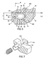
- FIG. 3 is a sectional view of mated flanges of the turbomachine of FIG. 2 .
- FIG. 4 is a plan view of one of the flanges of FIG. 2 including a seal-containing channel.
- FIG. 5 is a sectional view of the seal of FIG. 4 in a relaxed condition.
- FIG. 6 is a longitudinal sectional view of an end portion of the seal.
- FIG. 7 is an exploded view of the seal end portion of FIG. 6 .
- FIG. 8 is a longitudinal sectional view of an alternate seal end portion.
- FIG. 9 is a plan view of a flange having a channel containing the seal of FIG. 8 .
- FIG. 1 shows a turbomachine 20 having a central longitudinal axis 500 which forms an axis of rotation of the turbomachine rotors.
- the axis 500 falls along a transverse horizontal centerplane 502 .
- the turbomachine has a case assembly including an exemplary front (upstream) case 22 , intermediate case 24 , and rear case 26 .
- the intermediate case 24 is shown having ends fore and aft 28 and 30 at junctions with the front and rear cases.
- FIG. 2 shows the intermediate case 24 as including upper and lower halves 32 and 34 .
- these halves are symmetric across a vertical centerplane 504 .
- the halves 32 and 34 are joined along respective pairs of flanges 40 A, 42 A and 40 B, 42 B having faces 50 and 52 at junctions along the horizontal centerplane 502 .
- the flanges of each pair may be secured together such as via bolting.
- its interior surface 54 ( FIG. 3 ) varies in diameter relative to the centerline 500 to accommodate the diameters of the various rotating components.
- the flanges generally follow such change in radius.
- the surface 50 may initially be essentially flat and uninterrupted. A series of channel segments 60 may then be machined through the surface 50 to accommodate associated seal segments 62 .
- FIG. 3 shows a channel 60 closely spaced apart from the interior surface 54 .
- An exemplary channel 60 is essentially a right channel with a pair of sidewalls 70 and 72 and a base 74 with rounded junctions 76 and 78 .
- FIG. 4 shows the channel 60 as extending between a first end 80 and second end 82 .
- FIGS. 3 and 5 show further details of an exemplary seal 62 .
- the exemplary seal is a spring compression seal having a straight body formed by a C-sectioned outer jacket (seal member) 94 and a coiled energizing spring 96 concentrically within the jacket (e.g., along a seal centerline (axis) 510 ).
- the exemplary spring 96 has an outer diameter labeled as D S .
- the exemplary jacket 94 has a diameter D J which forms a relaxed thickness of the seal and jacket normal to a plane 512 discussed below.
- the jacket extends more than 180° around the axis 510 between edges 97 and 98 to form two sealing faces.
- the exemplary jacket extends approximately 270° around the axis 510 in a relaxed condition.
- the seal body and its axis 510 extend from a first axial end 100 to a second axial end 102 which, when installed, fall close to the channel segment ends 80 and 82 .
- there is a pressure gradient across the seal For example, there may be high internal pressure within the case and relatively low external pressure.
- the internal environment may also be relatively high temperature. It is advantageous to orient the seal so that the gap 99 between edges 97 and 98 faces the relatively high pressure/temperature environment. Due, however, to the gap, the seal center of gravity 514 ( FIG. 5 ) is shifted away from the gap. This center of gravity offset can cause the straight seal to roll into an undesirable orientation.
- the pressure difference across the seal may further encourage rolling.
- the seal may roll in any of several situations.
- FIG. 6 shows exemplary means as including an end block 120 mounted at the first end 100 of the seal body.
- the exemplary block 120 includes an inboard face 122 and an outboard face 124 .
- FIG. 7 shows the block as having a planform/cross-section corresponding to the cross-sectional shape of the channel so as to interfit with the channel to prevent seal rotation about the seal body axis.
- the exemplary block 120 has a base 130 and side faces 132 and 134 normal thereto. In the exemplary block 120 , there are rounded transition between the base and side faces.
- the exemplary block has a central aperture accommodating a screw 140 (e.g., a socket head machine screw). The threaded shaft of the screw is received in a retainer 142 whose perimeter is captured by the spring 96 .
- the seal jacket and spring are cut to a desired length (e.g., as a unit).
- the block 120 is machined (e.g., from bar or strip stock).
- the screw 140 and retainer 142 are mated to the block and inserted into the spring.
- the block is oriented relative to the jacket and tack welded thereto.
- the tack weld of the block to the adjacent jacket end preserves the relative orientation during handling and initial stages of installation.
- the seal assembly is then placed in the channel.
- the seal assembly may be transiently secured in place via material such as adhesive, wax, grease, or the like. This may be particularly desirable in situations where the channel is or becomes inverted during assembly. This material may be sacrificed (e.g., melted/vaporized) upon turbomachine operation.
- the seal Upon compressive assembly of the two flanges, the seal is compressed. This seal compression may break the tack weld. With the tack weld broken, the screw and retainer serve to retain the block to the segment. This retention may help prevent undesirable ingestion of the block by the turbomachine 20 (e.g., when the case is next opened). In some implementations, the retention may provide a residual orientation maintaining function for the jacket (e.g., a frictional retention).
- FIG. 8 shows an alternative block 150 otherwise similar to the block 120 but wherein the second side face 154 is displaced asymmetrically of the first face 152 by a protruding portion 160 which would extend beyond the associated channel sidewall. Accordingly, FIG. 9 shows a branch or alcove 170 at the associated end of the channel to accommodate the portion 160 .
- An exemplary turbomachine 20 is a stationary industrial gas turbine (IGT) or steam turbine used for electrical power generation. Implementations of the invention may involve: (1) remanufacture/retrofit of an existing turbomachine; and/or (2) a reengineering of an existing turbomachine configuration prior to manufacture of further units.
- An exemplary remanufacture/retrofit implementation is performed on-site with the turbomachine shut down.
- the upper and lower case halves are unbolted and separated along their junction.
- the channels are then machined (e.g., via conventional milling) in the associated flanges.
- the seals may then be inserted in the respective channels.
- the case halves may be reassembled and the bolts tightened to compress the seals.
- the channels are machined in the flanges of the upper case half. This permits machining to be performed away from the rest of the turbomachine so that there is better access to the flanges and less chance of introducing debris to the turbomachine. Although machining may be performed with the upper case half inverted, reassembly involves facing the channels downward.
Abstract
Description
Claims (20)
Priority Applications (1)
| Application Number | Priority Date | Filing Date | Title |
|---|---|---|---|
| US11/550,947 US7736122B1 (en) | 2005-10-20 | 2006-10-19 | Self-orienting seals and methods |
Applications Claiming Priority (2)
| Application Number | Priority Date | Filing Date | Title |
|---|---|---|---|
| US72946805P | 2005-10-20 | 2005-10-20 | |
| US11/550,947 US7736122B1 (en) | 2005-10-20 | 2006-10-19 | Self-orienting seals and methods |
Publications (1)
| Publication Number | Publication Date |
|---|---|
| US7736122B1 true US7736122B1 (en) | 2010-06-15 |
Family
ID=42237527
Family Applications (1)
| Application Number | Title | Priority Date | Filing Date |
|---|---|---|---|
| US11/550,947 Active 2029-03-05 US7736122B1 (en) | 2005-10-20 | 2006-10-19 | Self-orienting seals and methods |
Country Status (1)
| Country | Link |
|---|---|
| US (1) | US7736122B1 (en) |
Cited By (8)
| Publication number | Priority date | Publication date | Assignee | Title |
|---|---|---|---|---|
| US20110187058A1 (en) * | 2010-02-03 | 2011-08-04 | Baker Hughes Incorporated | Composite Metallic Elastomeric Sealing Components for Roller Cone Drill Bits |
| US8544852B2 (en) | 2011-06-03 | 2013-10-01 | General Electric Company | Torsion seal |
| US20180195415A1 (en) * | 2017-01-10 | 2018-07-12 | United Technologies Corporation | Carbon seal spring retention |
| US10370994B2 (en) | 2015-05-28 | 2019-08-06 | Rolls-Royce North American Technologies Inc. | Pressure activated seals for a gas turbine engine |
| US10480337B2 (en) | 2017-04-18 | 2019-11-19 | Rolls-Royce North American Technologies Inc. | Turbine shroud assembly with multi-piece seals |
| US10746037B2 (en) | 2016-11-30 | 2020-08-18 | Rolls-Royce Corporation | Turbine shroud assembly with tandem seals |
| US11428328B2 (en) * | 2016-07-28 | 2022-08-30 | Flowserve Management Company | Shutoff seal for high temperature pressure balance valve and related methods |
| US20230383667A1 (en) * | 2022-05-31 | 2023-11-30 | Pratt & Whitney Canada Corp. | Joint between gas turbine engine components with bonded fastener(s) |
Citations (16)
| Publication number | Priority date | Publication date | Assignee | Title |
|---|---|---|---|---|
| US3820799A (en) * | 1972-08-16 | 1974-06-28 | Commissariat Energie Atomique | Resilient metal gasket |
| US4114907A (en) * | 1976-09-09 | 1978-09-19 | Commissariat A L'energie Atomique | Resilient metal gasket |
| US4153281A (en) * | 1977-08-12 | 1979-05-08 | Vetco, Inc. | Misalignment connector with retained internal spherical seal |
| US4218067A (en) * | 1979-02-02 | 1980-08-19 | Pressure Science Incorporated | Multi-ply sealing rings |
| US4284479A (en) * | 1978-12-01 | 1981-08-18 | Didier Engineering Gmbh | Sealing arrangement for the oven chamber door on a coking oven |
| EP0134068A1 (en) * | 1983-05-19 | 1985-03-13 | Borg-Warner Corporation | Mechanical seal |
| US4561662A (en) * | 1983-12-29 | 1985-12-31 | Commissariat A L'energie Atomique | Flexible metal sealing joint incorporating expendable projecting portions |
| US4602888A (en) * | 1983-06-07 | 1986-07-29 | Commissariat A L'energie Atomique | Flexible metallic joint |
| US5022663A (en) * | 1988-09-08 | 1991-06-11 | Commissariat A L'energie Atomique | Metal gasket or joint provided with an extremely high unit-area pressure |
| US5354072A (en) * | 1989-12-19 | 1994-10-11 | Specialist Sealing Limited | Hollow metal sealing rings |
| US5797604A (en) * | 1995-12-25 | 1998-08-25 | Ckd Corporation | Metal gasket |
| US20030133792A1 (en) * | 2002-01-15 | 2003-07-17 | Srikanth Vedantam | Composite tubular woven seal for an inner compressor discharge case |
| US6631910B2 (en) * | 2001-04-23 | 2003-10-14 | Commissariat A L'energie Atomique | Elastic metal gasket with offset projecting parts |
| US7198303B2 (en) * | 2003-03-31 | 2007-04-03 | Metex Mfg. Corporation | Exhaust pipe joint and seal |
| US7372933B2 (en) * | 2004-07-08 | 2008-05-13 | Mitsubishi Heavy Industries, Ltd. | Radioactive-material container, metal gasket for sealing the radioactive-material container, and method of manufacturing the metal gasket |
| US7497443B1 (en) * | 2005-05-03 | 2009-03-03 | The United States Of America As Represented By The Administrator Of The National Aeronautics And Space Administration | Resilient flexible pressure-activated seal |
-
2006
- 2006-10-19 US US11/550,947 patent/US7736122B1/en active Active
Patent Citations (16)
| Publication number | Priority date | Publication date | Assignee | Title |
|---|---|---|---|---|
| US3820799A (en) * | 1972-08-16 | 1974-06-28 | Commissariat Energie Atomique | Resilient metal gasket |
| US4114907A (en) * | 1976-09-09 | 1978-09-19 | Commissariat A L'energie Atomique | Resilient metal gasket |
| US4153281A (en) * | 1977-08-12 | 1979-05-08 | Vetco, Inc. | Misalignment connector with retained internal spherical seal |
| US4284479A (en) * | 1978-12-01 | 1981-08-18 | Didier Engineering Gmbh | Sealing arrangement for the oven chamber door on a coking oven |
| US4218067A (en) * | 1979-02-02 | 1980-08-19 | Pressure Science Incorporated | Multi-ply sealing rings |
| EP0134068A1 (en) * | 1983-05-19 | 1985-03-13 | Borg-Warner Corporation | Mechanical seal |
| US4602888A (en) * | 1983-06-07 | 1986-07-29 | Commissariat A L'energie Atomique | Flexible metallic joint |
| US4561662A (en) * | 1983-12-29 | 1985-12-31 | Commissariat A L'energie Atomique | Flexible metal sealing joint incorporating expendable projecting portions |
| US5022663A (en) * | 1988-09-08 | 1991-06-11 | Commissariat A L'energie Atomique | Metal gasket or joint provided with an extremely high unit-area pressure |
| US5354072A (en) * | 1989-12-19 | 1994-10-11 | Specialist Sealing Limited | Hollow metal sealing rings |
| US5797604A (en) * | 1995-12-25 | 1998-08-25 | Ckd Corporation | Metal gasket |
| US6631910B2 (en) * | 2001-04-23 | 2003-10-14 | Commissariat A L'energie Atomique | Elastic metal gasket with offset projecting parts |
| US20030133792A1 (en) * | 2002-01-15 | 2003-07-17 | Srikanth Vedantam | Composite tubular woven seal for an inner compressor discharge case |
| US7198303B2 (en) * | 2003-03-31 | 2007-04-03 | Metex Mfg. Corporation | Exhaust pipe joint and seal |
| US7372933B2 (en) * | 2004-07-08 | 2008-05-13 | Mitsubishi Heavy Industries, Ltd. | Radioactive-material container, metal gasket for sealing the radioactive-material container, and method of manufacturing the metal gasket |
| US7497443B1 (en) * | 2005-05-03 | 2009-03-03 | The United States Of America As Represented By The Administrator Of The National Aeronautics And Space Administration | Resilient flexible pressure-activated seal |
Cited By (14)
| Publication number | Priority date | Publication date | Assignee | Title |
|---|---|---|---|---|
| US8967301B2 (en) * | 2010-02-03 | 2015-03-03 | Baker Hughes Incorporated | Composite metallic elastomeric sealing components for roller cone drill bits |
| US20110187058A1 (en) * | 2010-02-03 | 2011-08-04 | Baker Hughes Incorporated | Composite Metallic Elastomeric Sealing Components for Roller Cone Drill Bits |
| US10151148B2 (en) | 2010-02-03 | 2018-12-11 | Baker Hughes Incorporated | Composite metallic elastomeric sealing components for roller cone drill bits |
| US8544852B2 (en) | 2011-06-03 | 2013-10-01 | General Electric Company | Torsion seal |
| US10370994B2 (en) | 2015-05-28 | 2019-08-06 | Rolls-Royce North American Technologies Inc. | Pressure activated seals for a gas turbine engine |
| US11428328B2 (en) * | 2016-07-28 | 2022-08-30 | Flowserve Management Company | Shutoff seal for high temperature pressure balance valve and related methods |
| US11940053B2 (en) * | 2016-07-28 | 2024-03-26 | Flowserve Pte. Ltd. | Shutoff seal assemblies and related valve assemblies and methods |
| US20220403939A1 (en) * | 2016-07-28 | 2022-12-22 | Flowserve Management Company | Shutoff seal assemblies and related valve assemblies and methods |
| US10746037B2 (en) | 2016-11-30 | 2020-08-18 | Rolls-Royce Corporation | Turbine shroud assembly with tandem seals |
| US20180195415A1 (en) * | 2017-01-10 | 2018-07-12 | United Technologies Corporation | Carbon seal spring retention |
| US10718234B2 (en) * | 2017-01-10 | 2020-07-21 | United Technologies Corporation | Carbon seal spring retention |
| US11761352B2 (en) * | 2017-01-10 | 2023-09-19 | United Technologies Corporation | Carbon seal spring retention |
| US10480337B2 (en) | 2017-04-18 | 2019-11-19 | Rolls-Royce North American Technologies Inc. | Turbine shroud assembly with multi-piece seals |
| US20230383667A1 (en) * | 2022-05-31 | 2023-11-30 | Pratt & Whitney Canada Corp. | Joint between gas turbine engine components with bonded fastener(s) |
Similar Documents
| Publication | Publication Date | Title |
|---|---|---|
| US7736122B1 (en) | Self-orienting seals and methods | |
| US8039751B2 (en) | Motor and compressor with the same | |
| US6431550B1 (en) | Hydrogen seal ring having seal at ring intersegment | |
| CN101529667B (en) | Flexible RF seal for coaxial cable connector | |
| CN102102587B (en) | Exhaust turbine supercharger | |
| EP2620613B1 (en) | Sealing structure for turbocharger housing | |
| CA2552667C (en) | Tandem dual element intershaft carbon seal | |
| US20100007133A1 (en) | Axially moveable spool connector | |
| US5431534A (en) | Removable inspection hole plug | |
| JPH11507427A (en) | Steam seal exhaust system | |
| CN102713161A (en) | Means for locking a sealing ring on a turbine wheel | |
| EP0122509A1 (en) | Restrained pipe joint | |
| CN102439348A (en) | Pressure vessel for a high pressure press | |
| US9328625B2 (en) | Ram bearing assembly, seal assembly therefor and associated method | |
| KR20150020562A (en) | Exhaust-gas turbocharger | |
| US20190390571A1 (en) | Annular casting and shrink-fitted part of an aircraft turbine engine | |
| CA1216608A (en) | Hazardous location expansion fitting | |
| JPH0771617A (en) | Divided mechanical end-face seal | |
| EP0029686B1 (en) | Continuous self-locking spiral wound seal | |
| US9145914B2 (en) | Modular crankshaft | |
| EP2634379B1 (en) | Compression Sleeve Seal | |
| US11946548B2 (en) | Coil spring carbon face seal | |
| CN112594410B (en) | Top entry valve rod type ball valve | |
| US20060263208A1 (en) | Split case seals and methods | |
| EP2472069B1 (en) | Conduit for turbomachine and method |
Legal Events
| Date | Code | Title | Description |
|---|---|---|---|
| AS | Assignment |
Owner name: PARKER-HANNIFIN CORPORATION,OHIO Free format text: ASSIGNMENT OF ASSIGNORS INTEREST;ASSIGNOR:STONE, STEPHEN S.;REEL/FRAME:018411/0826 Effective date: 20061019 |
|
| STCF | Information on status: patent grant |
Free format text: PATENTED CASE |
|
| FPAY | Fee payment |
Year of fee payment: 4 |
|
| MAFP | Maintenance fee payment |
Free format text: PAYMENT OF MAINTENANCE FEE, 8TH YEAR, LARGE ENTITY (ORIGINAL EVENT CODE: M1552) Year of fee payment: 8 |
|
| AS | Assignment |
Owner name: PARKER INTANGIBLES, LLC, OHIO Free format text: ASSIGNMENT OF ASSIGNORS INTEREST;ASSIGNOR:PARKER-HANNIFIN CORPORATION;REEL/FRAME:045843/0859 Effective date: 20180405 |
|
| MAFP | Maintenance fee payment |
Free format text: PAYMENT OF MAINTENANCE FEE, 12TH YEAR, LARGE ENTITY (ORIGINAL EVENT CODE: M1553); ENTITY STATUS OF PATENT OWNER: LARGE ENTITY Year of fee payment: 12 |