US7726205B2 - Transducer for a rotating body - Google Patents
Transducer for a rotating body Download PDFInfo
- Publication number
- US7726205B2 US7726205B2 US11/835,829 US83582907A US7726205B2 US 7726205 B2 US7726205 B2 US 7726205B2 US 83582907 A US83582907 A US 83582907A US 7726205 B2 US7726205 B2 US 7726205B2
- Authority
- US
- United States
- Prior art keywords
- load cell
- axle
- hub
- assembly
- joined
- Prior art date
- Legal status (The legal status is an assumption and is not a legal conclusion. Google has not performed a legal analysis and makes no representation as to the accuracy of the status listed.)
- Active
Links
Images


Classifications
-
- G—PHYSICS
- G01—MEASURING; TESTING
- G01L—MEASURING FORCE, STRESS, TORQUE, WORK, MECHANICAL POWER, MECHANICAL EFFICIENCY, OR FLUID PRESSURE
- G01L3/00—Measuring torque, work, mechanical power, or mechanical efficiency, in general
- G01L3/02—Rotary-transmission dynamometers
- G01L3/14—Rotary-transmission dynamometers wherein the torque-transmitting element is other than a torsionally-flexible shaft
-
- G—PHYSICS
- G01—MEASURING; TESTING
- G01L—MEASURING FORCE, STRESS, TORQUE, WORK, MECHANICAL POWER, MECHANICAL EFFICIENCY, OR FLUID PRESSURE
- G01L5/00—Apparatus for, or methods of, measuring force, work, mechanical power, or torque, specially adapted for specific purposes
- G01L5/16—Apparatus for, or methods of, measuring force, work, mechanical power, or torque, specially adapted for specific purposes for measuring several components of force
- G01L5/161—Apparatus for, or methods of, measuring force, work, mechanical power, or torque, specially adapted for specific purposes for measuring several components of force using variations in ohmic resistance
- G01L5/1627—Apparatus for, or methods of, measuring force, work, mechanical power, or torque, specially adapted for specific purposes for measuring several components of force using variations in ohmic resistance of strain gauges
Definitions
- Wheel force transducer or load cells for measuring forces along or moments about three orthogonal axes are known.
- the wheel force transducer typically is mounted between and to a vehicle spindle and a portion of a vehicle rim.
- the transducer measures forces and moments reacted through a wheel assembly at the spindle as the vehicle is operated.
- this transducer includes a load cell body having a rigid central member, a rigid annular ring and a plurality of tubular members extending radially and joining the central member to the annular ring.
- a plurality of sensing circuits are mounted to the plurality of tubular members.
- the rigid central member is mounted to the vehicle spindle, while the annular ring is attached to the vehicle rim.
- An encoder measures the angular position of the load cell body allowing the forces transmitted through the radial tubular members to be resolved with respect to an orthogonal stationary coordinate system.
- An external slip ring assembly provides power to and receives signals from the sensors on the load cell body.
- aspects of the present invention relate to measuring and/or sensing forces and/or moments applied to a rotating body for example a wheel of a vehicle such as but not limited to a motorcycle.
- a first aspect comprises a load cell assembly for sensing force and/or moment components on a rotating body supported by a frame.
- the assembly includes an axle having opposite ends joined to the frame.
- a hub is supported by the axle and rotatable about a longitudinal axis thereof.
- a load cell body joined to the hub and the rotating body is used to sense force and/or moment components between the hub and the rotating body.
- a second aspect comprises a combination of a frame portion of a motorcycle or similar wheel assembly and a load cell assembly for sensing force and/or moment components on the motorcycle or similar wheel assembly.
- the load cell assembly includes an axle mounted at each end to the frame portion and a hub supported by the axle.
- a rim is provided and a tire is supported on the rim.
- a load cell body is operatively joined to the hub and the rim.
- a third aspect comprises a load cell assembly for sensing force and/or moment components on a rotating body supported by a frame.
- the assembly includes an axle joined to the frame on at least one end of the axle.
- a hub is supported by the axle and rotatable about a longitudinal axis thereof.
- a load cell body is joined to the hub and the rotating body to sense force and/or moment components between the hub and the rotating body.
- a slip ring assembly is disposed in the hub having a first member movable relative to a second member, the first member being rotatable with the hub.
- FIG. 1A is a side elevational view of a rear motorcycle wheel having a load cell system
- FIG. 1B is a sectional view of the rear motorcycle wheel of FIG. 1A taken along lines 1 B- 1 B;
- FIG. 2A is a side elevational view of a front motorcycle wheel having a load cell system
- FIG. 2B is a sectional view of the front motorcycle wheel of FIG. 2A taken along lines 2 B- 2 B;
- FIG. 3 is a side elevational view of a load cell
- FIG. 4 is a sectional view of the load cell of FIG. 3 taken along lines 4 - 4 ;
- FIG. 5 is a perspective view of a slip ring and brush assembly with parts separated
- FIG. 6A is a side elevational view of another rear motorcycle wheel having a load cell system
- FIG. 6B is a sectional view of the rear motorcycle wheel of FIG. 6A taken along lines 6 B- 6 B;
- FIG. 6C is an enlarged portion of FIG. 6B with the rim and spokes removed;
- FIG. 7A is a side elevational view of another front motorcycle wheel having a load cell system
- FIG. 7B is a sectional view of the front motorcycle wheel of FIG. 7A taken along lines 7 B- 7 B;
- FIG. 7C is an enlarged portion of FIG. 7B with the rim removed.
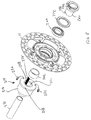
- FIG. 8 is an exploded perspective view of a hub assembly for the rear motorcycle wheel of FIG. 6A .
- FIGS. herein provided illustrate load cell systems well-suited for measuring force and moment components of a rotating body, and in one embodiment, a rotating body rotating on and about an axle supported at each end.
- a rotating body is a rolling wheel on, for instance, a trailer, cart or a vehicle such as but not limited to motorcycles.
- a motorcycle application will be used in view of its particular usefulness.
- FIGS. 1A and 1B illustrate a load cell system 10 as applied to a rear wheel assembly 13 of a motorcycle, wherein the motorcycle is not shown in its entirety, but can be considered as represented by sprocket 11 and swing arm 17 .
- FIGS. 2A and 2B illustrate a load cell system 10 ′ as applied to a front wheel assembly 19 of a motorcycle, wherein the motorcycle is not shown in its entirety, but can be considered as represented by frame portion (front forks) 15 .
- the load cell system 10 ′ is substantially similar to the load cell system 10 . Accordingly, where the same reference numbers have been used those parts have the same function.
- load cell system 10 generally includes a hub and axle assembly 12 , a transducer 14 and a tire and rim assembly 16 .
- the hub assembly 12 and elements connected thereto rotate about a longitudinal axis of an axle 18 that extends between and is joined to portions of the frame as is used to support the rear wheel of the motorcycle.
- a drive assembly Operatively connected to the hub assembly 12 is a drive assembly, herein the drive sprocket 11 although other forms of drive devices such as a shaft and gear assembly, belt, etc. can be used.
- a brake disc 30 is also illustrated as mounted to the other end of the hub assembly 12 .
- the size and location of the sprocket 11 and brake disc 30 will correspond to that made by the manufacturer, where the load cell system 10 can accommodate these elements. In this manner, the load cell system 10 can thereby accurately record real-life forces and moments present on a motorcycle wheel assembly.
- the hub assembly 12 is split, herein generally along the centerline of wheel assembly and comprises portions 40 and 42 .
- Hub portions 40 , 42 are joined together with the transducer 14 located therebetween with fasteners 43 .
- coupling teeth 46 can be provided to effectively transmit loads therebetween by increasing friction by the increased surface area provided by the mating teeth.
- the transducer has a central hub 64 and annular ring 66 .
- the hub portions 40 and 42 are joined to the central hub 64
- a rim adapter assembly 67 is joined with fasteners 65 to the annular ring 66 (which can include mating teeth) and to a wheel rim 69 with fasteners 75 .
- the transducer 14 is a separate component from rim adapter assembly 67 and one or both hub portions 40 , 42 , which conveniently allows the transducer 14 to be used many times with different types of wheel assemblies since then only the hub portions 40 , 42 and/or rim adapter assembly 67 need be specifically designed to particular wheel assembly.
- the transducer 14 for measuring force and moment components is secured to the hub assembly 12 and to rim adapter assembly 67 and used to support a tire on rim 69 .
- the transducer 14 thus replaces a portion of the rim and carries force and moment loads between the hub 12 and the tire.
- various forms of transducers can be used and incorporated in a manner as taught herein; however one particularly convenient transducer is as described in U.S. Pat. No. 5,969,268, the content of which is herein incorporated by reference in its entirety, wherein actual dimensions may be changed in order to accommodate the expected loads, size constraints and sensitivity.
- transducer 14 includes an integral load cell body 62 fabricated from a single block of material.
- the body 62 includes the rigid central hub 64 and the rigid annular ring 66 that is concentric with the central hub 64 .
- a plurality of radial tubes 70 joins the central hub 64 to the annular ring 66 .
- the plurality of radial tubes 70 comprises four tubes 71 , 72 , 73 and 74 .
- Each of the tubes 71 - 74 extend radially from the central hub 64 toward the annular ring 66 along corresponding longitudinal axes.
- the plurality of radial tubes 70 are spaced at equal angular intervals about a central axis indicated at 76 .
- flexure members 81 , 82 , 83 and 84 join an end of each radial tube 71 - 74 , respectively, to the annular ring 66 .
- the flexure members 81 - 84 are compliant for displacements of each corresponding radial tube 71 - 74 along the corresponding longitudinal axes.
- a plurality of sensors can be mounted on the plurality of tubes 70 to sense strain therein.
- the plurality of sensors can be located on the plurality of radial tubes 70 to provide an indication of bending stresses therein, in one embodiment, the strain sensors are mounted conventionally to provide an output signal indicative of shear stresses in the walls of the plurality of radial tubes 70 .
- four sets of strain sensors are provided on each tube 71 - 74 , preferably, approximately at the center of the longitudinal length of each tube.
- a first pair of strain sensors is provided on an upwardly facing portion of each radial tube 71 - 74 .
- a second pair of strain sensors is mounted on a downwardly facing surface approximately 180 degrees from the first pair of strain sensors.
- the first and second pairs of strain sensors on each tube 71 - 74 are connected in a conventional Wheatstone bridge to form a first sensing circuit on each radial tube 71 - 74 .
- a third pair of strain sensors is mounted approximately 90 degrees from the first pair of strain sensors while a fourth pair of strain sensors is mounted approximately 180 degrees from the third pair of strain sensors.
- the third and fourth pairs of strain sensors on each tube 71 - 74 are also connected in a conventional Wheatstone bridge to form a second sensing circuit on each radial tube 71 - 74 .
- the plurality of sensors comprises resistive strain gages.
- the plurality of sensors can function as shear sensors to provide an indication of shear stresses created in the radial tubes 70 .
- the plurality of sensors can be mounted to the radial tubes 70 to function as bending sensors to provide an indication of bending stresses in the radial tubes 70 .
- the bending sensors can be located at a root of the tube or start of the fillet joining each tube 71 - 74 to the central hub 64 .
- other forms of sensing devices such as but not limited to optically based sensors or capacitively based sensors can also be used.
- the flexures 81 - 84 can be used as sensing structures with suitable sensing devices detecting strain or displacement thereof.
- each radial tube 71 - 74 eight individual shear-sensing Wheatstone bridges can be used.
- the number of sensing circuits can be increased or decreased, depending on the number of radial tubes used.
- Output signals from the sensors or sensing circuits are indicative of force and moment components transmitted between the central hub 64 and the annular ring 66 in up to six degrees of freedom. It should be understood that the number of strain sensors and the number of sensing circuits can be reduced if measured forces and moments of less than six degrees of freedom is desired. Further details regarding resolving the signals from the sensors of the transducer 14 as force and moment measurements are described in U.S. Pat. No. 5,969,268; however, again it should be understood that other forms of transducers may be used.
- power is supplied to and output signals are obtained from the plurality of sensors by a controller and/or recorder 112 through a slip ring assembly 114 as the tire rim 69 , transducer 14 and hub 12 with elements connected thereto rotate on bearings 120 .
- a first embodiment of a slip ring assembly 114 includes an outer member 130 secured to the central hub 64 so as to rotate therewith such as with a pin through aperture 132 .
- An inner member 134 is secured to the axle 18 and remains stationary therewith.
- a key 136 can be provided to mate with a corresponding longitudinal groove 138 provided in the axle 18 , which can be solid.
- a brush and slip ring assembly 139 are operably coupled to members 130 and 132 in the annular space therebetween.
- an encoder assembly 140 can also be provided in the annular space. Cabling 144 from the brush assembly 139 with respect to the inner member 134 can extend along the length of the groove 138 , while cabling 146 from the brush assembly 139 with respect to the outer member 130 can be routed to circuitry of the transducer 14 .
- the slip ring assembly 114 and bearings 120 are held in place longitudinally along axle 18 through a concentric loading assembly 151 around the axle 18 .
- the concentric loading assembly 151 includes spacers 150 , 152 and 154 (each having a bore through which the axle 18 extends) in compression along with the inner races of the bearings 120 and inner member 134 when the axle 18 is placed in tension by axle nut 156 . It should be noted that the location of the slip ring assembly 114 on the axle 18 allows seals 162 used to protect the bearings 120 and also the slip ring assembly 114 , while the overall design allows access to the brush assembly 139 when repair is necessary.
- an external encoder 170 to monitor the angular position of the wheel assembly can be used.
- a sprocket or similar rotating member 176 can be used to drive a drive wheel of the encoder mounted somewhere else on the motorcycle.
- FIGS. 6A , 6 B and 6 C illustrate a load cell system 10 ′′ as applied to another rear wheel assembly 13 ′ of a motorcycle, wherein the motorcycle is not shown in its entirety, but can be considered as represented by sprocket 11 and swing arm 17 .
- FIGS. 7A , 73 and 7 B illustrate a load cell system 10 ′′′ as applied to another front wheel assembly 19 ′ of a motorcycle, wherein the motorcycle is not shown in its entirety, but can be considered as represented by frame portion (front forks) 15 .
- the load cell systems 10 ′′ and 10 ′′′ are substantially similar to each other, but have also have similar components to those discussed above with respect to the load cell systems 10 and 10 ′. Accordingly, where the same reference numbers have been used those parts have the same function as described above.
- load cell system 10 ′′ generally includes the split hub (portions 40 , 42 ) and axle assembly 12 , the transducer 14 and the tire and rim assembly 16 , which rotate about and on the axle shaft 18 that extends between and is joined portions of the frame as is used to support the rear wheel of the motorcycle.
- the hub portions 40 , 42 are joined to the sprocket 11 and brake disc 30 , respectively, as well as to the central hub 64 of transducer 14 .
- the annular ring 66 of transducer 14 is joined to the rim 69 using a spoke assembly 200 comprising a spoke hub support 202 and a plurality of spokes 204 .
- the spoke hub support 202 includes portions 206 and 208 suitably fastened such as with bolts to annular ring 66 on opposite sides thereof.
- This construction conveniently allows the transducer 14 to be used many times with different types of wheel assemblies where the hub portions 40 , 42 and/or spoke assembly 200 need be specifically designed to a particular wheel assembly.
- the slip ring assembly 214 includes an outer member 216 secured to the central hub 64 so as to rotate therewith such as with a pin through aperture 218 .
- An inner member 220 is secured to the axle 18 and remains stationary therewith.
- a keyway 221 in the inner member 220 can be provided to mate key elements on a spacer described below.
- a brush and slip ring assembly (not illustrated but similar to that of slip ring 114 ) are operably coupled to members 216 and 220 (schematically separated in FIGS. 63 and 6C ). Connectors 230 and 232 connect to transducer 14 , while wires 234 extend outwardly toward an end of the axle 18 . If desired, an encoder assembly can be provided in the slip ring assembly 214 , or an external encoder can be used. A suitable slip ring assembly is available from Michigan Scientific Corporation of Charlevoix, Mich., USA.
- concentric loading assembly 250 includes an axle spacers 259 , 260 and load spacer 262 with ends thereof cooperating with each other so as to mount and support bearing assembly 264 .
- axle spacer 260 includes a longitudinal groove 280 parallel to axle 18 through which wires 234 extend and then out through aperture 282 and guided through a channel 284 in a wire guide 286 proximate swing arm 17 .
- axle spacer 266 and load spacer 268 have ends that cooperate so as to mount and support bearing assembly 270 .
- a sleeve 271 can be disposed along the axle radially inward from inner member 220 . The thickness of the sleeve 271 allows the various components supported by the axle to adapt to the diameters of different axles.
- the axle spacers 260 , 266 , load spacers 262 , 268 , inner races of bearings 264 , 270 and inner member 220 (each having a bore through which the axle 18 extends) are loaded in compression with tightening of axle nut 275 and tension on the axle 18 .
- Each end further includes seals 272 and 274 to prevent water and other contaminates from reaching the slip ring assembly 214 .
- slip ring assembly 114 , 214 are located on the axle 18 between the bearings and in the hub 12 preferably inline with the central hub 64 , or stated another way so as to intersect with a central plane of the load cell body 62 .
- the load cell body 62 is not sensitive to loads (such as chain or braking loads on a motorcycle) that are not reacted to the annular ring 66 (i.e. tire contact patch) of the load cell body 62 , which are rather shunted into the bearings.
- FIGS. 7A-7C A similar construction is used in the front wheel assembly of FIGS. 7A-7C , where the same reference numbers have been used to identify similar functioning elements as those described above.
- the axle 18 is supported at both ends of the frame
- aspects herein described can be used on a frame where the frame supports the rotating body such as a wheel from one side.
- aspects of the invention can be used on a single sided swing arm as found on some motorcycles.
- tire testing machines and truck axles commonly have a quill shaft to drive the rotating body.
- the slip ring assembly can be mounted so that a first member rotates with the hub (which need not always be split) and a second member is held stationary where the wires exit toward the frame along a groove in the axle and/or through a channel formed in an axle spacer as described above.
- a hollow or partial hollow axle e.g. FIG.
- an aperture 291 can be provided at any point along the length where the wires 234 from the slip ring assembly can then extend into and thus along the axle within its bore. Rings or brushes of the slip ring assembly can also be directly attached to or formed on the axle if desired.
Abstract
Description
Claims (26)
Priority Applications (1)
| Application Number | Priority Date | Filing Date | Title |
|---|---|---|---|
| US11/835,829 US7726205B2 (en) | 2006-08-08 | 2007-08-08 | Transducer for a rotating body |
Applications Claiming Priority (2)
| Application Number | Priority Date | Filing Date | Title |
|---|---|---|---|
| US83655406P | 2006-08-08 | 2006-08-08 | |
| US11/835,829 US7726205B2 (en) | 2006-08-08 | 2007-08-08 | Transducer for a rotating body |
Publications (2)
| Publication Number | Publication Date |
|---|---|
| US20080034894A1 US20080034894A1 (en) | 2008-02-14 |
| US7726205B2 true US7726205B2 (en) | 2010-06-01 |
Family
ID=39082568
Family Applications (1)
| Application Number | Title | Priority Date | Filing Date |
|---|---|---|---|
| US11/835,829 Active US7726205B2 (en) | 2006-08-08 | 2007-08-08 | Transducer for a rotating body |
Country Status (5)
| Country | Link |
|---|---|
| US (1) | US7726205B2 (en) |
| EP (1) | EP2057449A2 (en) |
| JP (1) | JP2010500561A (en) |
| CN (1) | CN101501467A (en) |
| WO (1) | WO2008021106A2 (en) |
Cited By (6)
| Publication number | Priority date | Publication date | Assignee | Title |
|---|---|---|---|---|
| US8720285B2 (en) | 2010-12-17 | 2014-05-13 | Industrial Technology Research Institute | Non-contact measurement signal transmission system and method thereof |
| US20150033875A1 (en) * | 2013-08-01 | 2015-02-05 | Mts Systems Corporation | Two-Axis Sensor Body For A Load Transducer |
| US9638654B2 (en) | 2013-11-25 | 2017-05-02 | Oil States Industries, Inc. | Method and system for health monitoring of composite elastomeric flexible elements |
| US10272720B2 (en) * | 2015-12-23 | 2019-04-30 | Mts Systems Coporation | Wheel support having a transducer sensor body |
| US10591373B2 (en) | 2013-08-01 | 2020-03-17 | Mts Systems Corporation | Load transducer having a biasing assembly |
| US20210325264A1 (en) * | 2019-01-28 | 2021-10-21 | Nidec Copal Electronics Corporation | Elastic body and force sensor using the same |
Families Citing this family (7)
| Publication number | Priority date | Publication date | Assignee | Title |
|---|---|---|---|---|
| JP2000034544A (en) * | 1998-07-16 | 2000-02-02 | Kawasaki Steel Corp | Steel sheet excellent in pitting resistance |
| US8322901B2 (en) * | 2010-01-28 | 2012-12-04 | Michelotti William M | Illuminated vehicle wheel with bearing seal slip ring assembly |
| ITMO20120107A1 (en) * | 2012-04-20 | 2013-10-21 | Tecnoelettra Impianti S R L | DEVICE FOR THE MEASUREMENT OF THE MOTORCYCLE TORQUE TRANSMITTED TO THE WHEELS OF MOTORIZED VEHICLES |
| JP2015203595A (en) * | 2014-04-11 | 2015-11-16 | スズキ株式会社 | Traction sensor of saddle type vehicle |
| WO2017112929A1 (en) * | 2015-12-23 | 2017-06-29 | Mts Systems Corporation | Transducer sensor body |
| JP6605365B2 (en) * | 2016-03-10 | 2019-11-13 | 川崎重工業株式会社 | Arrangement structure of load measuring device for front wheel of motorcycle |
| FR3084157B1 (en) * | 2018-07-20 | 2021-07-02 | Commissariat Energie Atomique | CYCLE WHEEL HUB ALLOWS THE DETERMINATION OF THE DRIVE TORQUE AND THE DRIVE POWER PROVIDED BY THE CYCLIST |
Citations (20)
| Publication number | Priority date | Publication date | Assignee | Title |
|---|---|---|---|---|
| US4655080A (en) * | 1985-10-02 | 1987-04-07 | Theodore Ongaro | Dynamic tire balancing machine and method |
| US4811612A (en) | 1986-11-19 | 1989-03-14 | Ste Look | Method and device for measuring the torque transmitted by the driving wheel of a cycle and a cycle equipped with said device |
| US4966380A (en) * | 1988-05-17 | 1990-10-30 | STE Look rue de la Pigue | Driving wheel for a bicycle or the like, including a sensor for measuring the transmitted torque, and a bicycle equipped with such a wheel |
| US4969694A (en) | 1987-11-16 | 1990-11-13 | Skf France | Wheel hub mounting with a pulse transmitter |
| US5018597A (en) | 1988-12-28 | 1991-05-28 | Aisin Seiki Kabushiki Kaisha | Free wheel hub control system |
| US5025884A (en) | 1988-12-28 | 1991-06-25 | Aisin Seiki Kabushiki Kaisha | Free wheel hub system |
| US5097702A (en) | 1988-01-07 | 1992-03-24 | The Torrington Company | Automobile wheel hub |
| DE4431029A1 (en) | 1994-08-31 | 1996-03-21 | Karlheinz Nicolai | Torque measurement value transmitter esp. for bicycles with two circular discs |
| EP0841549A1 (en) | 1996-11-07 | 1998-05-13 | Mavic S.A. | Hub for cycle wheel and wheel with such a hub |
| DE19857025A1 (en) | 1997-12-10 | 1999-07-01 | Honda Motor Co Ltd | Device for measuring force exerted on wheel at point where it touches ground, for motorbike, etc. |
| WO1999045350A1 (en) | 1998-03-04 | 1999-09-10 | Tune Corporation | Apparatus and method for sensing power in a bicycle |
| US5969268A (en) | 1997-07-15 | 1999-10-19 | Mts Systems Corporation | Multi-axis load cell |
| US6002327A (en) * | 1998-11-04 | 1999-12-14 | Ford Global Technologies, Inc. | Low tire warning system with axle torque signal |
| US6038933A (en) | 1997-07-15 | 2000-03-21 | Mts Systems Corporation | Multi-axis load cell |
| US6688168B1 (en) * | 2002-11-19 | 2004-02-10 | Delphi Technologies, Inc. | Method for determining axle load of a moving vehicle |
| WO2004027366A1 (en) | 2002-09-20 | 2004-04-01 | Ecole Polytechnique Federale De Lausanne (Epfl) | Device for measuring the amplitude of a force produced on an axis and a vehicle provided with said device |
| US6729178B2 (en) | 1999-09-17 | 2004-05-04 | Mts Systems Corporation | Output spindle shaft for a rolling wheel testing apparatus |
| US6845675B2 (en) * | 2000-12-15 | 2005-01-25 | Mts Systems Corporation | Multi-axis load cell |
| WO2006015284A2 (en) | 2004-07-29 | 2006-02-09 | Saris Cycling Group, Inc. | Exercise device with power input measuring capability and user applied resistance mechanism |
| US7028540B2 (en) * | 2004-02-26 | 2006-04-18 | Denso Corporation | Device and method for detecting force acting on tire |
-
2007
- 2007-08-08 CN CNA2007800296954A patent/CN101501467A/en active Pending
- 2007-08-08 WO PCT/US2007/017580 patent/WO2008021106A2/en active Application Filing
- 2007-08-08 US US11/835,829 patent/US7726205B2/en active Active
- 2007-08-08 EP EP07811165A patent/EP2057449A2/en not_active Withdrawn
- 2007-08-08 JP JP2009523827A patent/JP2010500561A/en not_active Withdrawn
Patent Citations (23)
| Publication number | Priority date | Publication date | Assignee | Title |
|---|---|---|---|---|
| US4655080A (en) * | 1985-10-02 | 1987-04-07 | Theodore Ongaro | Dynamic tire balancing machine and method |
| US4811612A (en) | 1986-11-19 | 1989-03-14 | Ste Look | Method and device for measuring the torque transmitted by the driving wheel of a cycle and a cycle equipped with said device |
| US4969694A (en) | 1987-11-16 | 1990-11-13 | Skf France | Wheel hub mounting with a pulse transmitter |
| US5097702A (en) | 1988-01-07 | 1992-03-24 | The Torrington Company | Automobile wheel hub |
| US5097701A (en) | 1988-01-07 | 1992-03-24 | The Torrington Company | Automobile wheel hub |
| US4966380A (en) * | 1988-05-17 | 1990-10-30 | STE Look rue de la Pigue | Driving wheel for a bicycle or the like, including a sensor for measuring the transmitted torque, and a bicycle equipped with such a wheel |
| US5018597A (en) | 1988-12-28 | 1991-05-28 | Aisin Seiki Kabushiki Kaisha | Free wheel hub control system |
| US5025884A (en) | 1988-12-28 | 1991-06-25 | Aisin Seiki Kabushiki Kaisha | Free wheel hub system |
| DE4431029A1 (en) | 1994-08-31 | 1996-03-21 | Karlheinz Nicolai | Torque measurement value transmitter esp. for bicycles with two circular discs |
| EP0841549A1 (en) | 1996-11-07 | 1998-05-13 | Mavic S.A. | Hub for cycle wheel and wheel with such a hub |
| US5969268A (en) | 1997-07-15 | 1999-10-19 | Mts Systems Corporation | Multi-axis load cell |
| US6038933A (en) | 1997-07-15 | 2000-03-21 | Mts Systems Corporation | Multi-axis load cell |
| DE19857025A1 (en) | 1997-12-10 | 1999-07-01 | Honda Motor Co Ltd | Device for measuring force exerted on wheel at point where it touches ground, for motorbike, etc. |
| WO1999045350A1 (en) | 1998-03-04 | 1999-09-10 | Tune Corporation | Apparatus and method for sensing power in a bicycle |
| US6418797B1 (en) | 1998-03-04 | 2002-07-16 | Graber Products, Inc. | Apparatus and method for sensing power in a bicycle |
| US6002327A (en) * | 1998-11-04 | 1999-12-14 | Ford Global Technologies, Inc. | Low tire warning system with axle torque signal |
| US6729178B2 (en) | 1999-09-17 | 2004-05-04 | Mts Systems Corporation | Output spindle shaft for a rolling wheel testing apparatus |
| US6845675B2 (en) * | 2000-12-15 | 2005-01-25 | Mts Systems Corporation | Multi-axis load cell |
| WO2004027366A1 (en) | 2002-09-20 | 2004-04-01 | Ecole Polytechnique Federale De Lausanne (Epfl) | Device for measuring the amplitude of a force produced on an axis and a vehicle provided with said device |
| US6688168B1 (en) * | 2002-11-19 | 2004-02-10 | Delphi Technologies, Inc. | Method for determining axle load of a moving vehicle |
| US7028540B2 (en) * | 2004-02-26 | 2006-04-18 | Denso Corporation | Device and method for detecting force acting on tire |
| WO2006015284A2 (en) | 2004-07-29 | 2006-02-09 | Saris Cycling Group, Inc. | Exercise device with power input measuring capability and user applied resistance mechanism |
| US20060079382A1 (en) | 2004-07-29 | 2006-04-13 | Lassanske Todd W | Exercise device with power input measuring capability and user applied resistance mechanism |
Non-Patent Citations (2)
| Title |
|---|
| Official Search Report of the European Patent Office in counterpart foreign application No. PCT/US2007/017580 filed Aug. 8, 2007. |
| Written Opinion of the European Patent Office in counterpart foreign application No. PCT/US2007/017580 filed Aug. 8, 2007. |
Cited By (8)
| Publication number | Priority date | Publication date | Assignee | Title |
|---|---|---|---|---|
| US8720285B2 (en) | 2010-12-17 | 2014-05-13 | Industrial Technology Research Institute | Non-contact measurement signal transmission system and method thereof |
| US20150033875A1 (en) * | 2013-08-01 | 2015-02-05 | Mts Systems Corporation | Two-Axis Sensor Body For A Load Transducer |
| US9778122B2 (en) * | 2013-08-01 | 2017-10-03 | Mts Systems Corporation | Two-axis sensor body for a load transducer |
| US10495533B2 (en) | 2013-08-01 | 2019-12-03 | Mts Systems Corporation | Load transducer with lockup assembly |
| US10591373B2 (en) | 2013-08-01 | 2020-03-17 | Mts Systems Corporation | Load transducer having a biasing assembly |
| US9638654B2 (en) | 2013-11-25 | 2017-05-02 | Oil States Industries, Inc. | Method and system for health monitoring of composite elastomeric flexible elements |
| US10272720B2 (en) * | 2015-12-23 | 2019-04-30 | Mts Systems Coporation | Wheel support having a transducer sensor body |
| US20210325264A1 (en) * | 2019-01-28 | 2021-10-21 | Nidec Copal Electronics Corporation | Elastic body and force sensor using the same |
Also Published As
| Publication number | Publication date |
|---|---|
| US20080034894A1 (en) | 2008-02-14 |
| EP2057449A2 (en) | 2009-05-13 |
| WO2008021106A3 (en) | 2008-07-10 |
| WO2008021106A2 (en) | 2008-02-21 |
| CN101501467A (en) | 2009-08-05 |
| JP2010500561A (en) | 2010-01-07 |
Similar Documents
| Publication | Publication Date | Title |
|---|---|---|
| US7726205B2 (en) | Transducer for a rotating body | |
| US8887581B2 (en) | Load-measuring bearing unit | |
| US7683274B2 (en) | Force-measurement cell and a connection pin fitted with such a cell | |
| JP4817213B2 (en) | Method and apparatus for measuring tire rolling resistance | |
| CN100334435C (en) | Multi-axis load cell | |
| US5447060A (en) | Chasis dynamometer with improved torque measurement | |
| US20060130595A1 (en) | Multi axis load cell body | |
| US20090180722A1 (en) | Load sensing wheel end | |
| JPH0641898B2 (en) | Multi-component measurement disk car | |
| JPH03209016A (en) | Hub bearing unit | |
| JP6656904B2 (en) | Vehicle test device and simulated wheel used in vehicle test device | |
| US6845675B2 (en) | Multi-axis load cell | |
| KR20050092753A (en) | Hub unit with sensor | |
| US6439063B1 (en) | Wheel load transducer | |
| JP4352162B2 (en) | Torque detection device for drive shaft | |
| CN111656153B (en) | Method and device for dynamometer testing of motor vehicle | |
| Gobbi et al. | Sensors for Measuring Forces and Moments With Application to Ground Vehicles Design and Engineering | |
| JPH11173929A (en) | Apparatus for measuring wheel working force | |
| US6308583B1 (en) | Axle force and moment transducer | |
| US6799479B1 (en) | Wheel load measurement system | |
| US8961022B2 (en) | Rolling bearing for rotatively mounting a machine element | |
| JP2010151676A (en) | Tire acting force detection device | |
| JPH07117668A (en) | Longitudinal force detecting device for vehicle | |
| US10272720B2 (en) | Wheel support having a transducer sensor body | |
| EP2438318B1 (en) | Load-measuring bearing unit |
Legal Events
| Date | Code | Title | Description |
|---|---|---|---|
| AS | Assignment |
Owner name: MTS SYSTEMS CORPORATION, MINNESOTA Free format text: ASSIGNMENT OF ASSIGNORS INTEREST;ASSIGNORS:MEYER, RICHARD A.;OLSON, DOUGLAS J.;KUNSCH, IAN T.;AND OTHERS;REEL/FRAME:019901/0422 Effective date: 20070925 Owner name: MTS SYSTEMS CORPORATION,MINNESOTA Free format text: ASSIGNMENT OF ASSIGNORS INTEREST;ASSIGNORS:MEYER, RICHARD A.;OLSON, DOUGLAS J.;KUNSCH, IAN T.;AND OTHERS;REEL/FRAME:019901/0422 Effective date: 20070925 |
|
| STCF | Information on status: patent grant |
Free format text: PATENTED CASE |
|
| FPAY | Fee payment |
Year of fee payment: 4 |
|
| AS | Assignment |
Owner name: JPMORGAN CHASE BANK, N.A., AS ADMINISTRATIVE AGENT, ILLINOIS Free format text: SUPPLEMENTAL CONFIRMATORY GRANT OF SECURITY INTEREST IN UNITED STATES PATENTS;ASSIGNOR:MTS SYSTEMS CORPORATION;REEL/FRAME:039258/0587 Effective date: 20160705 Owner name: JPMORGAN CHASE BANK, N.A., AS ADMINISTRATIVE AGENT Free format text: SUPPLEMENTAL CONFIRMATORY GRANT OF SECURITY INTEREST IN UNITED STATES PATENTS;ASSIGNOR:MTS SYSTEMS CORPORATION;REEL/FRAME:039258/0587 Effective date: 20160705 |
|
| FPAY | Fee payment |
Year of fee payment: 8 |
|
| AS | Assignment |
Owner name: MTS SYSTEMS CORPORATION, MINNESOTA Free format text: RELEASE BY SECURED PARTY;ASSIGNOR:JPMORGAN CHASE BANK, N.A., AS ADMINISTRATIVE AGENT;REEL/FRAME:055911/0315 Effective date: 20210407 |
|
| MAFP | Maintenance fee payment |
Free format text: PAYMENT OF MAINTENANCE FEE, 12TH YEAR, LARGE ENTITY (ORIGINAL EVENT CODE: M1553); ENTITY STATUS OF PATENT OWNER: LARGE ENTITY Year of fee payment: 12 |