US7725252B2 - Device and method for positioning and controlling railway vehicles with ultra-large bandwidth - Google Patents
Device and method for positioning and controlling railway vehicles with ultra-large bandwidth Download PDFInfo
- Publication number
- US7725252B2 US7725252B2 US10/564,836 US56483606A US7725252B2 US 7725252 B2 US7725252 B2 US 7725252B2 US 56483606 A US56483606 A US 56483606A US 7725252 B2 US7725252 B2 US 7725252B2
- Authority
- US
- United States
- Prior art keywords
- rail
- transmitter
- rail vehicle
- signals
- vehicle
- Prior art date
- Legal status (The legal status is an assumption and is not a legal conclusion. Google has not performed a legal analysis and makes no representation as to the accuracy of the status listed.)
- Expired - Fee Related, expires
Links
Images

Classifications
-
- B—PERFORMING OPERATIONS; TRANSPORTING
- B61—RAILWAYS
- B61L—GUIDING RAILWAY TRAFFIC; ENSURING THE SAFETY OF RAILWAY TRAFFIC
- B61L23/00—Control, warning, or like safety means along the route or between vehicles or vehicle trains
- B61L23/08—Control, warning, or like safety means along the route or between vehicles or vehicle trains for controlling traffic in one direction only
- B61L23/14—Control, warning, or like safety means along the route or between vehicles or vehicle trains for controlling traffic in one direction only automatically operated
-
- B—PERFORMING OPERATIONS; TRANSPORTING
- B61—RAILWAYS
- B61L—GUIDING RAILWAY TRAFFIC; ENSURING THE SAFETY OF RAILWAY TRAFFIC
- B61L27/00—Central railway traffic control systems; Trackside control; Communication systems specially adapted therefor
- B61L27/20—Trackside control of safe travel of vehicle or vehicle train, e.g. braking curve calculation
-
- B—PERFORMING OPERATIONS; TRANSPORTING
- B61—RAILWAYS
- B61L—GUIDING RAILWAY TRAFFIC; ENSURING THE SAFETY OF RAILWAY TRAFFIC
- B61L3/00—Devices along the route for controlling devices on the vehicle or vehicle train, e.g. to release brake, to operate a warning signal
- B61L3/02—Devices along the route for controlling devices on the vehicle or vehicle train, e.g. to release brake, to operate a warning signal at selected places along the route, e.g. intermittent control simultaneous mechanical and electrical control
- B61L3/08—Devices along the route for controlling devices on the vehicle or vehicle train, e.g. to release brake, to operate a warning signal at selected places along the route, e.g. intermittent control simultaneous mechanical and electrical control controlling electrically
- B61L3/12—Devices along the route for controlling devices on the vehicle or vehicle train, e.g. to release brake, to operate a warning signal at selected places along the route, e.g. intermittent control simultaneous mechanical and electrical control controlling electrically using magnetic or electrostatic induction; using radio waves
- B61L3/125—Devices along the route for controlling devices on the vehicle or vehicle train, e.g. to release brake, to operate a warning signal at selected places along the route, e.g. intermittent control simultaneous mechanical and electrical control controlling electrically using magnetic or electrostatic induction; using radio waves using short-range radio transmission
-
- G—PHYSICS
- G01—MEASURING; TESTING
- G01S—RADIO DIRECTION-FINDING; RADIO NAVIGATION; DETERMINING DISTANCE OR VELOCITY BY USE OF RADIO WAVES; LOCATING OR PRESENCE-DETECTING BY USE OF THE REFLECTION OR RERADIATION OF RADIO WAVES; ANALOGOUS ARRANGEMENTS USING OTHER WAVES
- G01S5/00—Position-fixing by co-ordinating two or more direction or position line determinations; Position-fixing by co-ordinating two or more distance determinations
- G01S5/02—Position-fixing by co-ordinating two or more direction or position line determinations; Position-fixing by co-ordinating two or more distance determinations using radio waves
-
- B—PERFORMING OPERATIONS; TRANSPORTING
- B61—RAILWAYS
- B61L—GUIDING RAILWAY TRAFFIC; ENSURING THE SAFETY OF RAILWAY TRAFFIC
- B61L2205/00—Communication or navigation systems for railway traffic
- B61L2205/04—Satellite based navigation systems, e.g. GPS
Definitions
- the average distance tends to increase between the stations of urban railway lines relative to the older network. This distance which is approximately 500 m on the older underground Parisian network has, for instance, been increased to 2000 m on the automated line, “Mraumor”, built in 1998.
- This extension of the interval between the stations which depends on the planning of the towns to be supplied, enables to increase the commercial speed of the transport trains to reach speeds close to 50 km/h whereas they are only about 25 km/h on the former networks. This gain in speed does not only aim at reducing the average travel time for the user, but should also enable sufficient flow of passengers to meet the so-called rush hours.
- the purpose of the present invention is hence to provide a device and a method for positioning and controlling rail vehicles with ultra wide frequency bands simple in their design and in their operating mode, with very high transfer rate of data and economical, limiting the risks of interferences with other wireless communication systems, thereby enabling rail vehicle-ground telecommunication with a radioelectric coverage, in particular in tunnel, close to 100% and highly available, very reliable hodometry of the rail vehicle and a perception of the front environment of said vehicle for the detection of obstacles and hence reinforced safety of the passengers.
- Such system also enables direct communication between vehicles, which proved necessary in certain operating modes.
- the invention relates to a device for positioning and controlling rail vehicles including fixed stations comprising first transmission-reception means of signals and a central control station to which are connected the fixed stations and controlling a transport zone.
- rail vehicle is meant here any guided transport system, regardless whether the guiding system is operated by railways, longitudinal sleepers or any other means.
- the invention also concerns a method for positioning and controlling rail vehicles including fixed stations comprising first transmission-reception means of signals and a central control station to which are connected the fixed stations.
- the present invention also concerns the following characteristics which should be considered individually or according to all their technically possible combinations:
- the device and the method for controlling and positioning as described previously may be used advantageously for automated underground transport trains.
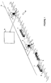
- FIG. 1 is schematic representation of the device for positioning and controlling rail vehicles according to an embodiment of the invention.
- FIG. 1 shows a device for positioning and controlling rail vehicles according to a particular embodiment of the invention.
- This device includes fixed stations 1 comprising first transmission-reception means 2 of signals. It also includes a central control station 3 controlling a transport zone and to which are connected the fixed stations 1 .
- This central control station 3 sends rail operation control orders.
- such orders include navigation instructions for at least one rail vehicle 4 localised in the transport zone controlled by said central station 3 .
- Such orders may comprise moreover a communication intended for the passengers on-board said rail vehicle 4 such as traffic information, messages multimedia, etc.
- the ground information processed by the fixed stations 1 may be aggregated among al the fixed stations 1 by a point-to-point link 5 for instance by optic fibre so that the central control station 3 knows comprehensively the speeds, positions and states of al the rail vehicles 4 in circulation on a line or over the whole transport zone.
- the central control station 3 may comprise a processing unit for centralising and processing the data sent by the fixed stations and means for displaying said data on a screen in real time.
- Each rail vehicle 4 comprises second transmission-reception means 6 of signals.
- the signals transmitted by the first and second transmission-reception means of signals 2 , 6 contain a specific identifier of the transmitter and at least one message. Indeed, along an urban guided transport line, there are a finite number of stations and hence of fixed stations 1 associated with each of these stations, of the order of a few tens. There are also a finite number of rail vehicles 4 moving in the transport zone controlled by the central control station 3 .
- Each fixed station 1 , and hence each station, and each rail vehicle 4 may therefore be ascribed a single identifier like the PRN codes PRN of the GPS satellites (Global positioning system).
- identifier is meant here a specific code and a specific identity which are ascribed to a transmitter. These identifiers are known by the whole transport network but not divulged to the outside since such elements are kept confidential to improve the stealthiness of the communications and thereby increase global safety of the transport system of transport. These single identifiers per rail vehicle 4 and fixed station 1 modulate a pulse string according to an ultra wide band technique. In radio communication, the gap between successive pulses may, indeed be kept constant or varied by a piece of information, a code or both at the same time.
- said specific identifier is obtained by pseudo-random encoding.
- a single radio transmission channel is available typically in a tunnel.
- several rail vehicles or fixed stations should be able to access simultaneously said radio channel.
- all transmitting over the same channel in band L to each rail vehicle element or to each fixed communication station of the transport network is associated a particular code derived from a family (for example family of the Gold codes in the case of GPS satellites or still codes derived from families with orthogonal functions).
- a property particularly sought-after in this family of codes lies in its orthogonality properties which enable a given receiver to discriminate the signals, codes in this field, with minimal interferences.
- the signals of the first and second transmission-reception means 2 , 6 are radio signals with a very large passband whereof the frequency spectrum ranges between 1 and 10 GHz. Indeed, for such high frequencies, the tunnel behaves like an oversized wave guide. From then on, for tunnel sections of tunnel of several hundred meters, the signals of frequencies 1 to 10 GHz are attenuated much less. There results that the transmission balances of these signals are compatible with a range of the order of one kilometer. These signals are hence perfected surrounded in the frequency range propagating efficiently in an underground tunnel.
- the wide spectrum spread of the signals processed as well as the very small elementary duration (of the order of a nanosecond) of an ultra wide band signal enable to dispense with difficult propagation conditions in tunnel characterised by numerous multiple paths linked with the reflections against the walls as well as to signal spreads which may be as high, in tunnel, as several ten nanoseconds.
- the ultra wide band technology enables therefore optimal radioelectric coverage necessary to an automated driving system of rail vehicles such as an automated underground train.
- the first and second transmission-reception means 2 , 6 comprise for instance a wide band aerial 7 .
- Such aerial 7 may be, when a little directive radiation is requested, on-board for instance, a circular disk type monopole or a dipole formed of two circular disks.
- Such arrangement enables to provide the requested passband 1 to 10 GHz for disk diameters smaller than some ten centimeters.
- Such aerials 7 may also be placed, for instance in station for fixed stations 1 , at the focus of a parabola or of a wide band focus element in order to increase the directivity and hence the transmission balance of the ground-rail vehicle link.
- Each rail vehicle 4 and each fixed station 1 include processing means 8 for determining the identifier and at least said message of each signal received.
- each ultra wide band receiver may play the part, locally, of these different identifiers and attempt at decoding by correlation the signals from the first transmission-reception means 2 of the fixed stations 1 (stations) or from the second transmission-reception means 6 coming from the rail vehicles 4 , such as radioelectric range trains.
- Each transmission-reception means 2 , 6 has therefore:
- Each fixed station 1 may hence known the pieces of basic information relative to the rail vehicles 4 circulating in its coverage zone 9 . It is possible on the ground to measure remotely the speeds and positions of said rail vehicles 4 or still to receive such pieces of information prepared on-board the rail vehicle 4 on the base of the analysis of the ultra wide band signals exchanged between the ground and the vehicles 4 .
- All the rail vehicles 4 may calculate their distances to the downstream and upstream fixed stations where they are situated locally.
- the vehicles 4 may also acquire pieces of information regarding the identity, the speed and the position relative to the other vehicles 4 in the vicinity.
- This positioning and controlling device enables accurate train hodometry. It includes precise localisation of the rail vehicles 4 (trains . . . ) in the transport zone capable of authorising for exemplification purposes ⁇ goal shoot>>, i.e. the capacity of managing automatically the stoppage of rail vehicles 4 accurately before landing gates or still the entrance into a particular lane zone of a few hundred meters called block section.
- the rail vehicles 4 move following a single dimension along the lanes. Measuring the distance relative to a fixed reference upstream and/or downstream as based on the flight time of signals derived from pieces of geolocalised equipment and situated in upstream/downstream stations determines, with high degree of certainty and accuracy, the absolute position of the guided mobile.
- this duration corresponds to a distance travelled through the air of approximately 30 cm.
- a distance resolution equal to a fraction of this length may be obtained by processing the signal. This leads to a distance resolution of the order of several centimeters, which is compatible notably with the target shooting objective for an accurate stoppage before a landing gate of a rail vehicle 4 .
- the ultra wide band technology also enables to reach, notably by deriving from this distance, an ⁇ (actual speed measurement of the rail vehicle>>, realised without detriment to the cinematic capacities of the vehicles (no un-braked axle . . . ) and highly performing, including for low speeds (zero speed detection-vehicle stoppage).
- Each rail vehicle 4 also includes means for detecting passive obstacles on the lanes by the perception of the front environment of the vehicle by means of an ultra wide band radar technology.
- a lane locked on the incident code transmitted by the second transmission-reception means endeavours to detect passive obstacles in lane.
- Such surveillance authorises the detection of obstacles (objects left on the lane during night-time works, stone falls from a tunnel vault . . . ) or of other vehicles and enables to react on the speed programme of the train (emergency braking for instance in case of unexpected obstacle).
- surveillance function enables to operate the transport system according to particular modes such as docking the vehicles after breakdown or operating a line in dividable trains having, for example, a maximum of running elements in the centre of the line and a minimum at the ends.
- the invention also concerns a method for positioning and controlling rail vehicles 4 including fixed stations 1 comprising first transmission-reception means 2 of signals and a central control station 3 to which are connected the fixed stations 1 .
- Each rail vehicle 4 comprises second transmission-reception means of signals 6 .
- a specific identifier is determined for each of the first and second transmission-reception means 2 , 6 , said signals being non-sinewave radio signals with a very large passband whereof the frequency spectrum ranges between 1 and 10 GHz containing said identifier and at least one message.
- the identifier and at least said message of this signal are determined by processing means.
- Rail operation control orders are sent by the central control station.
- a railway line operation is performed according to two possible operating modes.
- the transport zone controlled by the central station 3 and wherein the rail vehicles 4 are displaced is divided into a grid of points defined by the repetition of a same elementary mesh of length D.
- the length D of the elementary mesh may be set typically to several hundred meters and the system then switches to so-called mode with fixed block sections.
- Rail operation control orders are then sent by the central control station 3 to each rail vehicle 4 so that a single vehicle is included any time over the length D.
- This operating mode in fixed blocks is the most common operating mode.
- the underground line a few kilometer long, is divided materially into a series of fixed length blocks.
- the automatic driving system processes the pieces of information derived from trains and the ground (speed, position, block inlet and occupancy detectors) in order to implement all possible means so that a single train occupies, at any time, a block.
- the fixed and on-board automatisms will dialogue, prepare and manage the stoppage, at the borderline of the upstream block, of a train attempting to enter a downstream block occupied by another train.
- the length D of the elementary mesh may also be variable with time and it is then a so-called deformable moving block mode.
- the length D of the elementary mesh is determined in real time from the signals transmitted by each rail vehicle 4 , said length being at least equal to the safety distance D min between each vehicle, the central station 3 sending rail operation control orders to each rail vehicle 4 for keeping said distance D between each vehicle.
- the railway line is not limited any longer in immovable blocks, but a central control station 3 receives the speed and position information from each of the rail vehicles 4 on the line. It calculates permanently safety interval before each of the trains enabling said trains to stop in safety mode if needed. According to the cinematic capacities of the trains (speed, braking capacities, adhesion), this distance evolves rapidly.
- the ground system calculates and sends in return, to each of the trains of the line, valid speed and itinerary authorisations for a limited time period (a few hundred milliseconds). This operating mode enables in theory to process a maximum of trains on the line and hence to optimise the transport resource.
- a mixed operating mode exists however.
- rendezvous manoeuvres should take place so that a train may push, when not in operating mode, the train broken down or become coupled with an extent train in order to provide for instance in the central zone of a particularly loaded line, an additional transport capacity.
- a train enters a block occupied and the system must manage the safety of such operation which therefore proves contrary to the basic operating principle of a line with fixed blocks.
- the device and the method for positioning and controlling rail vehicles 4 may advantageously be implemented to fulfil one or several of the following functions:
Abstract
Description
-
- each rail vehicle comprises second transmission-reception means of signals containing a specific identifier of the transmitter and at least one message,
- the signals transmitted by the first transmission-reception means fixed stations contain a specific identifier of the transmitter and at least one message,
- the central control station sends rail operation control orders,
- each rail vehicle and each fixed station include processing means for determining the identifier and at least said message of each signal received,
- the signals of the first and second transmission-reception means are non-sinewave radio signals with a very large passband whereof the frequency spectrum ranges between 1 and 10 GHz.
-
- each rail vehicle includes on the one hand, means for determining the position and the direction of said vehicle in the transport zone and, on the other hand, means for determining an actual speed measurement of said vehicle, said means receiving signals from the processing means,
- each rail vehicle includes means for detecting passive obstacles or other vehicles on the lanes receiving signals from said processing means,
- the localisation in the transport zone, the speed and the direction of each rail vehicle are determined on the one hand, and the detection of obstacles is realised on the other hand, in real time and simultaneously,
- said specific identifier is obtained by pseudo-random encoding,
- the rail operation control orders transmitted by the central station include navigation instructions of at least one rail vehicle,
- said orders comprise a communication for said rail vehicle,
- the central control station includes a processing unit for centralising and processing the data sent by the fixed stations and means for displaying said data on a screen in real time.
-
- each rail vehicle comprises second transmission-reception means of signals,
- a specific identifier is determined for each of the first and second transmission-reception means, said signals being non-sinewave radio signals with a very large passband whereof the frequency spectrum ranges between 1 and 10 GHz containing said identifier and at least one message,
- for each of the signals received by the fixed station and by each rail vehicle, the identifier and at least said message of this signal are determined by processing means,
- rail operation control orders are sent by the central control station.
-
- the transport zone controlled by the central station and wherein the rail vehicles are displaced, is divided into a grid of points defined by the repetition of a same elementary mesh of length D,
- the length D of the elementary mesh is set typically to a few hundred meters,
- rail operation control orders are sent by the central control station to each rail vehicle so that a single vehicle is included any time over the length D,
- rail operation control orders are sent by the central control station to at least two rail vehicles to conduct a rendezvous manoeuvre over the length D,
- the length D of the elementary mesh is variable with time,
- the length D of the elementary mesh is determined in real time from the signals transmitted by each rail vehicle, said length being at least equal to the safety distance Dmin between each vehicle, the central station sending rail operation control orders to each rail vehicle for keeping said distance D between each vehicle,
- passive obstacles on the lanes are determined by the second transmission-reception means and for each rail vehicle in motion.
-
- One or several processing lanes locked onto the codes of the fixed stations 1 (stations) and rail vehicles 4 (trains) in radio range. They collect the operating data transmitted (identity, speeds, positions, state of the trains and stations . . . );
- One lane or several processing lanes calculate the speeds relative to the fixed
stations 1 or rail vehicles 4 with which the ultra wide band communication is established; - One lane calculates the distance between stations in order to determine the position of the train 4 between two identified intermediate stations of the transport zone;
- One lane scans for the appearance of new rail vehicles 4 or fixed
stations 1 in the radio coverage zone while generating locally all the vehicle codes 4 and fixedstations 1 and attempting to detected by correlation a new useful signal.
-
- i) Ground-rail vehicle communication 4,
- ii) Direct communication between rail vehicles 4,
- iii) Precise localisation of the rail vehicles 4 (trains . . . ) in the transport zone controlled by the central control station 3,
- iv) <<actual speed measurement of the rail vehicle>>, realised without detriment to the cinematic capacities of the vehicles (no un-braked axle . . . ) and highly performing, including for low speeds (zero speed detection-vehicle stoppage),
- v) surveillance for passive obstacles or other vehicles on the lanes by the perception of the front environment of the vehicle by means of an ultra wide band radar technology.
Claims (17)
Applications Claiming Priority (3)
| Application Number | Priority Date | Filing Date | Title |
|---|---|---|---|
| FR0350336 | 2003-07-16 | ||
| FR0350336A FR2857644B1 (en) | 2003-07-16 | 2003-07-16 | DEVICE AND METHOD FOR POSITIONING AND CONTROLLING RAILWAY VEHICLES WITH ULTRA - WIDE FREQUENCY BANDS. |
| PCT/FR2004/050336 WO2005007482A1 (en) | 2003-07-16 | 2004-07-15 | Device and method for positioning and controlling railway vehicles with ultra-large bandwidth |
Publications (2)
| Publication Number | Publication Date |
|---|---|
| US20060151672A1 US20060151672A1 (en) | 2006-07-13 |
| US7725252B2 true US7725252B2 (en) | 2010-05-25 |
Family
ID=33548334
Family Applications (1)
| Application Number | Title | Priority Date | Filing Date |
|---|---|---|---|
| US10/564,836 Expired - Fee Related US7725252B2 (en) | 2003-07-16 | 2004-07-15 | Device and method for positioning and controlling railway vehicles with ultra-large bandwidth |
Country Status (9)
| Country | Link |
|---|---|
| US (1) | US7725252B2 (en) |
| EP (1) | EP1648753B1 (en) |
| JP (1) | JP2007516121A (en) |
| CN (1) | CN1822976B (en) |
| AT (1) | ATE387366T1 (en) |
| DE (1) | DE602004012112T2 (en) |
| ES (1) | ES2299866T3 (en) |
| FR (1) | FR2857644B1 (en) |
| WO (1) | WO2005007482A1 (en) |
Cited By (30)
| Publication number | Priority date | Publication date | Assignee | Title |
|---|---|---|---|---|
| US20100114358A1 (en) * | 2005-11-14 | 2010-05-06 | Reiner Krapf | Power tool monitoring device |
| US20110093144A1 (en) * | 2009-03-17 | 2011-04-21 | Todd Goodermuth | System and method for communicating data in a train having one or more locomotive consists |
| US20110099413A1 (en) * | 2009-10-22 | 2011-04-28 | Jared Klineman Cooper | System and method for locomotive inter-consist equipment sparing and redundancy |
| US20120296562A1 (en) * | 2011-05-19 | 2012-11-22 | Carlson Richard C | Collision avoidance system for rail line vehicles |
| US8380363B2 (en) | 2008-03-27 | 2013-02-19 | Hetronic International, Inc. | Remote control system having a touchscreen for controlling a railway vehicle |
| US20140005863A1 (en) * | 2012-06-27 | 2014-01-02 | Alstom Transport Sa | Train and Method for Safely Determining the Configuration of such a Train |
| US8655517B2 (en) | 2010-05-19 | 2014-02-18 | General Electric Company | Communication system and method for a rail vehicle consist |
| US20140129060A1 (en) * | 2009-10-22 | 2014-05-08 | General Electric Company | System And Method For Vehicle Communication, Vehicle Control, And/Or Route Inspection |
| US20140142868A1 (en) * | 2012-11-18 | 2014-05-22 | Andian Technologies Ltd. | Apparatus and method for inspecting track in railroad |
| US8751127B2 (en) | 2011-11-30 | 2014-06-10 | General Electric Company | Position estimation system and method |
| US8798821B2 (en) | 2009-03-17 | 2014-08-05 | General Electric Company | System and method for communicating data in a locomotive consist or other vehicle consist |
| US20140236957A1 (en) * | 2013-02-15 | 2014-08-21 | Norfolk Southern Corporation | System and method for terminal capacity management |
| US8914170B2 (en) | 2011-12-07 | 2014-12-16 | General Electric Company | System and method for communicating data in a vehicle system |
| US8935022B2 (en) | 2009-03-17 | 2015-01-13 | General Electric Company | Data communication system and method |
| US9134411B2 (en) | 2011-11-30 | 2015-09-15 | General Electric Company | Distance estimation system and method for a railway vehicle |
| US9379775B2 (en) | 2009-03-17 | 2016-06-28 | General Electric Company | Data communication system and method |
| US9513630B2 (en) | 2010-11-17 | 2016-12-06 | General Electric Company | Methods and systems for data communications |
| US9566988B2 (en) | 2012-12-06 | 2017-02-14 | Siemens Aktiengesellschaft | Locating of vehicles |
| US9637147B2 (en) | 2009-03-17 | 2017-05-02 | General Electronic Company | Data communication system and method |
| US9650059B2 (en) | 2012-05-23 | 2017-05-16 | General Electric Company | System and method for inspecting a route during movement of a vehicle system over the route |
| US9956974B2 (en) | 2004-07-23 | 2018-05-01 | General Electric Company | Vehicle consist configuration control |
| US10144440B2 (en) | 2010-11-17 | 2018-12-04 | General Electric Company | Methods and systems for data communications |
| US10621451B1 (en) * | 2014-04-10 | 2020-04-14 | Waymo Llc | Image and video compression for remote vehicle assistance |
| US10778363B2 (en) | 2017-08-04 | 2020-09-15 | Metrom Rail, Llc | Methods and systems for decentralized rail signaling and positive train control |
| US11208125B2 (en) * | 2016-08-08 | 2021-12-28 | Transportation Ip Holdings, Llc | Vehicle control system |
| US11529981B2 (en) | 2020-01-31 | 2022-12-20 | Siemens Mobility, Inc. | Ultra-wideband based vital train tracking |
| US11780481B2 (en) | 2015-03-23 | 2023-10-10 | Metrom Rail, Llc | Methods and systems for worker protection system with ultra-wideband (UWB) based anchor network |
| US20230347949A1 (en) * | 2022-04-27 | 2023-11-02 | Rockwell Automation Technologies, Inc. | System and Method for Controlling Movers in an Independent Cart System During Heavy Traffic |
| US11814088B2 (en) | 2013-09-03 | 2023-11-14 | Metrom Rail, Llc | Vehicle host interface module (vHIM) based braking solutions |
| US11952028B2 (en) | 2019-04-08 | 2024-04-09 | Metrom Rail, Llc | Methods and systems for achieving vital ultra-wideband (UWB) based train control |
Families Citing this family (22)
| Publication number | Priority date | Publication date | Assignee | Title |
|---|---|---|---|---|
| EP2022697B1 (en) * | 2007-08-07 | 2010-02-03 | Alstom Ferroviaria S.P.A. | Communication system for vehicles particularly railway vehicles or the like and stationary units |
| US8290646B2 (en) * | 2008-03-27 | 2012-10-16 | Hetronic International, Inc. | Remote control system implementing haptic technology for controlling a railway vehicle |
| US8344877B2 (en) * | 2009-07-07 | 2013-01-01 | Bombardier Transportation Gmbh | Track worker safety system |
| CN102088442B (en) * | 2009-12-02 | 2015-04-01 | 王峥 | Vehicle-mounted multimedia information exchange system and method |
| DE102009060728A1 (en) * | 2009-12-21 | 2011-06-22 | Siemens Aktiengesellschaft, 80333 | Method and device for securing the route of track-bound vehicles |
| US9083861B2 (en) | 2010-04-09 | 2015-07-14 | Wabtec Holding Corp. | Visual data collection system for a train |
| CN101905704B (en) * | 2010-08-04 | 2012-03-14 | 北京全路通信信号研究设计院有限公司 | Method, equipment and system for monitoring railway equipment |
| NO331979B1 (en) * | 2010-09-17 | 2012-05-14 | Stiftelsen Norsar | System and method for early detection of trains |
| CN103183043B (en) * | 2011-12-27 | 2015-08-19 | 北京交通大学 | A kind of train positioning system |
| US9393977B2 (en) * | 2013-01-03 | 2016-07-19 | Wise Electronics, Llc | End of train video system |
| CN103171598B (en) * | 2013-04-12 | 2017-02-15 | 莱芜钢铁集团有限公司 | Method and system for positioning train |
| US20150060608A1 (en) | 2013-09-03 | 2015-03-05 | Metrom Rail, Llc | Rail Vehicle Signal Enforcement and Separation Control |
| FR3010678B1 (en) * | 2013-09-19 | 2015-10-16 | Alstom Transport Sa | COMMUNICATION DEVICE FOR A RAILWAY VEHICLE, RAIL VEHICLE EQUIPPED WITH SUCH A DEVICE |
| FR3019676B1 (en) | 2014-04-02 | 2017-09-01 | Alstom Transp Tech | METHOD FOR CALCULATING A POSITIONS INTERVAL OF A RAILWAY VEHICLE ON A RAILWAY AND ASSOCIATED DEVICE |
| WO2016154295A1 (en) | 2015-03-23 | 2016-09-29 | Metrom Rail, Llc | Worker protection system |
| JP2017088078A (en) * | 2015-11-16 | 2017-05-25 | 株式会社日立製作所 | Train safety device and signal security system |
| RU2663564C2 (en) * | 2016-07-13 | 2018-08-07 | Открытое Акционерное Общество "Российские Железные Дороги" | System for train traffic regulation |
| CN106314484B (en) * | 2016-08-09 | 2018-08-07 | 北京永安信通科技股份有限公司 | Vehicle positioning device and the mine locomotive for including the vehicle positioning device |
| EP3456606B1 (en) * | 2017-09-15 | 2020-07-15 | Aktiebolaget SKF | Position determination method and system |
| CN109334714A (en) * | 2018-08-16 | 2019-02-15 | 浙江浙大列车智能化工程技术研究中心有限公司 | The accurate shutdown system of train based on UWB wireless distance finding technology |
| DE102018217081B4 (en) | 2018-10-05 | 2020-06-25 | Audi Ag | Transport system and method for carrying out at least one transport order as well as associated transport unit for such a transport system |
| WO2023037473A1 (en) * | 2021-09-09 | 2023-03-16 | 三菱電機株式会社 | Railway management system, track number detection device, track number detection method, control circuit, and storage medium |
Citations (6)
| Publication number | Priority date | Publication date | Assignee | Title |
|---|---|---|---|---|
| US4873531A (en) * | 1987-11-20 | 1989-10-10 | Societe Anonyme Dite : Alsthom | Identification transponder for use when a vehicle passes a given point |
| EP0341826A2 (en) | 1988-05-09 | 1989-11-15 | Westinghouse Brake And Signal Holdings Limited | A railway signalling system |
| US5366183A (en) | 1992-02-11 | 1994-11-22 | Westinghouse Brake And Signal Holdings Limited | Railway signalling system |
| DE4336799A1 (en) | 1993-10-28 | 1995-05-04 | Sel Alcatel Ag | Device for the detection of, and reading out from, transponders which move relative to this device |
| US5420883A (en) | 1993-05-17 | 1995-05-30 | Hughes Aircraft Company | Train location and control using spread spectrum radio communications |
| DE19907466C1 (en) | 1999-02-13 | 2000-11-23 | Abb Daimler Benz Transp | Train sequence safety method for rail network allows second train to enter occupied track section with safety distance between successive trains maintained to prevent collision |
Family Cites Families (1)
| Publication number | Priority date | Publication date | Assignee | Title |
|---|---|---|---|---|
| EP1238501B1 (en) * | 1999-11-29 | 2008-03-12 | Multispectral Solutions, Inc. | Ultra-wideband data transmission system |
-
2003
- 2003-07-16 FR FR0350336A patent/FR2857644B1/en not_active Expired - Fee Related
-
2004
- 2004-07-15 WO PCT/FR2004/050336 patent/WO2005007482A1/en active IP Right Grant
- 2004-07-15 JP JP2006519978A patent/JP2007516121A/en active Pending
- 2004-07-15 CN CN2004800203458A patent/CN1822976B/en not_active Expired - Fee Related
- 2004-07-15 AT AT04767897T patent/ATE387366T1/en not_active IP Right Cessation
- 2004-07-15 EP EP04767897A patent/EP1648753B1/en not_active Not-in-force
- 2004-07-15 ES ES04767897T patent/ES2299866T3/en active Active
- 2004-07-15 US US10/564,836 patent/US7725252B2/en not_active Expired - Fee Related
- 2004-07-15 DE DE602004012112T patent/DE602004012112T2/en active Active
Patent Citations (6)
| Publication number | Priority date | Publication date | Assignee | Title |
|---|---|---|---|---|
| US4873531A (en) * | 1987-11-20 | 1989-10-10 | Societe Anonyme Dite : Alsthom | Identification transponder for use when a vehicle passes a given point |
| EP0341826A2 (en) | 1988-05-09 | 1989-11-15 | Westinghouse Brake And Signal Holdings Limited | A railway signalling system |
| US5366183A (en) | 1992-02-11 | 1994-11-22 | Westinghouse Brake And Signal Holdings Limited | Railway signalling system |
| US5420883A (en) | 1993-05-17 | 1995-05-30 | Hughes Aircraft Company | Train location and control using spread spectrum radio communications |
| DE4336799A1 (en) | 1993-10-28 | 1995-05-04 | Sel Alcatel Ag | Device for the detection of, and reading out from, transponders which move relative to this device |
| DE19907466C1 (en) | 1999-02-13 | 2000-11-23 | Abb Daimler Benz Transp | Train sequence safety method for rail network allows second train to enter occupied track section with safety distance between successive trains maintained to prevent collision |
Cited By (46)
| Publication number | Priority date | Publication date | Assignee | Title |
|---|---|---|---|---|
| US9956974B2 (en) | 2004-07-23 | 2018-05-01 | General Electric Company | Vehicle consist configuration control |
| US10065665B2 (en) | 2004-07-23 | 2018-09-04 | General Electric Company | Vehicle consist configuration control |
| US8190286B2 (en) * | 2005-11-14 | 2012-05-29 | Robert Bosch Gmbh | Machine tool monitoring device |
| US20100114358A1 (en) * | 2005-11-14 | 2010-05-06 | Reiner Krapf | Power tool monitoring device |
| US8509964B2 (en) | 2008-03-27 | 2013-08-13 | Hetronic International, Inc. | Remote control system having a touchscreen for controlling a railway vehicle |
| US8380363B2 (en) | 2008-03-27 | 2013-02-19 | Hetronic International, Inc. | Remote control system having a touchscreen for controlling a railway vehicle |
| US8483887B2 (en) | 2008-03-27 | 2013-07-09 | Hetronic International, Inc. | Remote control system having a touchscreen for controlling a railway vehicle |
| US8798821B2 (en) | 2009-03-17 | 2014-08-05 | General Electric Company | System and method for communicating data in a locomotive consist or other vehicle consist |
| US8583299B2 (en) | 2009-03-17 | 2013-11-12 | General Electric Company | System and method for communicating data in a train having one or more locomotive consists |
| US20110093144A1 (en) * | 2009-03-17 | 2011-04-21 | Todd Goodermuth | System and method for communicating data in a train having one or more locomotive consists |
| US8935022B2 (en) | 2009-03-17 | 2015-01-13 | General Electric Company | Data communication system and method |
| US9637147B2 (en) | 2009-03-17 | 2017-05-02 | General Electronic Company | Data communication system and method |
| US9379775B2 (en) | 2009-03-17 | 2016-06-28 | General Electric Company | Data communication system and method |
| US20110099413A1 (en) * | 2009-10-22 | 2011-04-28 | Jared Klineman Cooper | System and method for locomotive inter-consist equipment sparing and redundancy |
| US8645010B2 (en) * | 2009-10-22 | 2014-02-04 | General Electric Company | System and method for locomotive inter-consist equipment sparing and redundancy |
| US20140129060A1 (en) * | 2009-10-22 | 2014-05-08 | General Electric Company | System And Method For Vehicle Communication, Vehicle Control, And/Or Route Inspection |
| US9983593B2 (en) * | 2009-10-22 | 2018-05-29 | General Electric Company | System and method for vehicle communication, vehicle control, and/or route inspection |
| US9581998B2 (en) | 2009-10-22 | 2017-02-28 | General Electric Company | System and method for vehicle communication, vehicle control, and/or route inspection |
| US8903574B2 (en) * | 2009-10-22 | 2014-12-02 | General Electric Company | System and method for vehicle communication, vehicle control, and/or route inspection |
| US8655517B2 (en) | 2010-05-19 | 2014-02-18 | General Electric Company | Communication system and method for a rail vehicle consist |
| US10144440B2 (en) | 2010-11-17 | 2018-12-04 | General Electric Company | Methods and systems for data communications |
| US9513630B2 (en) | 2010-11-17 | 2016-12-06 | General Electric Company | Methods and systems for data communications |
| US20120296562A1 (en) * | 2011-05-19 | 2012-11-22 | Carlson Richard C | Collision avoidance system for rail line vehicles |
| US8812227B2 (en) * | 2011-05-19 | 2014-08-19 | Metrom Rail, Llc | Collision avoidance system for rail line vehicles |
| US9134411B2 (en) | 2011-11-30 | 2015-09-15 | General Electric Company | Distance estimation system and method for a railway vehicle |
| US8751127B2 (en) | 2011-11-30 | 2014-06-10 | General Electric Company | Position estimation system and method |
| US8914170B2 (en) | 2011-12-07 | 2014-12-16 | General Electric Company | System and method for communicating data in a vehicle system |
| US9650059B2 (en) | 2012-05-23 | 2017-05-16 | General Electric Company | System and method for inspecting a route during movement of a vehicle system over the route |
| US20140005863A1 (en) * | 2012-06-27 | 2014-01-02 | Alstom Transport Sa | Train and Method for Safely Determining the Configuration of such a Train |
| US9221479B2 (en) * | 2012-06-27 | 2015-12-29 | Alstom Transport Technologies | Train and method for safely determining the configuration of such a train |
| US20140142868A1 (en) * | 2012-11-18 | 2014-05-22 | Andian Technologies Ltd. | Apparatus and method for inspecting track in railroad |
| US9566988B2 (en) | 2012-12-06 | 2017-02-14 | Siemens Aktiengesellschaft | Locating of vehicles |
| US20140236957A1 (en) * | 2013-02-15 | 2014-08-21 | Norfolk Southern Corporation | System and method for terminal capacity management |
| US9171345B2 (en) * | 2013-02-15 | 2015-10-27 | Norfolk Southern Corporation | System and method for terminal capacity management |
| US11814088B2 (en) | 2013-09-03 | 2023-11-14 | Metrom Rail, Llc | Vehicle host interface module (vHIM) based braking solutions |
| US11831868B2 (en) | 2014-04-10 | 2023-11-28 | Waymo Llc | Image and video compression for remote vehicle assistance |
| US10621451B1 (en) * | 2014-04-10 | 2020-04-14 | Waymo Llc | Image and video compression for remote vehicle assistance |
| US11443525B1 (en) * | 2014-04-10 | 2022-09-13 | Waymo Llc | Image and video compression for remote vehicle assistance |
| US11780481B2 (en) | 2015-03-23 | 2023-10-10 | Metrom Rail, Llc | Methods and systems for worker protection system with ultra-wideband (UWB) based anchor network |
| US11208125B2 (en) * | 2016-08-08 | 2021-12-28 | Transportation Ip Holdings, Llc | Vehicle control system |
| US10778363B2 (en) | 2017-08-04 | 2020-09-15 | Metrom Rail, Llc | Methods and systems for decentralized rail signaling and positive train control |
| US11349589B2 (en) | 2017-08-04 | 2022-05-31 | Metrom Rail, Llc | Methods and systems for decentralized rail signaling and positive train control |
| US11700075B2 (en) | 2017-08-04 | 2023-07-11 | Metrom Rail, Llc | Methods and systems for decentralized rail signaling and positive train control |
| US11952028B2 (en) | 2019-04-08 | 2024-04-09 | Metrom Rail, Llc | Methods and systems for achieving vital ultra-wideband (UWB) based train control |
| US11529981B2 (en) | 2020-01-31 | 2022-12-20 | Siemens Mobility, Inc. | Ultra-wideband based vital train tracking |
| US20230347949A1 (en) * | 2022-04-27 | 2023-11-02 | Rockwell Automation Technologies, Inc. | System and Method for Controlling Movers in an Independent Cart System During Heavy Traffic |
Also Published As
| Publication number | Publication date |
|---|---|
| ES2299866T3 (en) | 2008-06-01 |
| ATE387366T1 (en) | 2008-03-15 |
| JP2007516121A (en) | 2007-06-21 |
| DE602004012112D1 (en) | 2008-04-10 |
| DE602004012112T2 (en) | 2009-02-19 |
| FR2857644A1 (en) | 2005-01-21 |
| EP1648753A1 (en) | 2006-04-26 |
| WO2005007482A1 (en) | 2005-01-27 |
| CN1822976B (en) | 2010-07-14 |
| FR2857644B1 (en) | 2006-03-10 |
| US20060151672A1 (en) | 2006-07-13 |
| CN1822976A (en) | 2006-08-23 |
| EP1648753B1 (en) | 2008-02-27 |
Similar Documents
| Publication | Publication Date | Title |
|---|---|---|
| US7725252B2 (en) | Device and method for positioning and controlling railway vehicles with ultra-large bandwidth | |
| Zhang et al. | Breaking the blockage for big data transmission: Gigabit road communication in autonomous vehicles | |
| US6418371B1 (en) | Traffic guidance system | |
| US7479919B2 (en) | Surface vehicle transponder | |
| RU2288509C1 (en) | Method for monitoring, tracking and controlling ground-based vehicles | |
| CN108769949A (en) | A kind of road test method of V2X equipment | |
| KR20020077285A (en) | Road traffic monitoring system | |
| Ansari et al. | Vehicle-to-vehicle real-time relative positioning using 5.9 GHz DSRC media | |
| Unterhuber et al. | Path loss models for train‐to‐train communications in typical high speed railway environments | |
| KR20160110457A (en) | Vehicle identification | |
| KR101714378B1 (en) | Management apparatus for communication performance of roadside equipment based on traffic information. and apparatus applied to the same | |
| CN110839209B (en) | Method for direct-view path discrimination and cooperative positioning among vehicles suitable for Internet of vehicles | |
| CN109727453B (en) | Passive radar system for highway traffic monitoring and monitoring method thereof | |
| Nakamura et al. | Road vehicle communication system for vehicle control using leaky coaxial cable | |
| Elbahhar et al. | Advanced train positioning/communication system | |
| Lehner et al. | Direct train‐to‐train communications at low UHF frequencies | |
| CN110065527A (en) | A kind of railway signal occlusion auxiliary system based on fiber grating | |
| Wang et al. | A channel awareness vehicle detector | |
| RU2348551C1 (en) | Centralised vehicle status and location monitoring method | |
| JP5008488B2 (en) | Metal object detection system | |
| CN113706866B (en) | Road jam monitoring method and device, electronic equipment and storage medium | |
| RU2547909C1 (en) | Crossing signal control method | |
| CN108594231A (en) | A kind of particular vehicle crossing priority radar detection method and its system | |
| Lim et al. | Making connected cars untraceable via dsrc radios | |
| Inoue et al. | Dedicated short-range communications (DSRC) for AHS services |
Legal Events
| Date | Code | Title | Description |
|---|---|---|---|
| AS | Assignment |
Owner name: CENTRE NATIONAL DE LA RECHERCHE SCIENTIFIQUE (CNRS Free format text: ASSIGNMENT OF ASSIGNORS INTEREST;ASSIGNORS:HEDDEBAUT, MARC;RIVENQ-MENHAJ, ATIKA;ROUVAEN, JEAN-MICHEL;AND OTHERS;REEL/FRAME:017318/0928 Effective date: 20060210 Owner name: INSTITUT NATIONAL DE RECHERCHE SUR LES TRANSPORTS Free format text: ASSIGNMENT OF ASSIGNORS INTEREST;ASSIGNORS:HEDDEBAUT, MARC;RIVENQ-MENHAJ, ATIKA;ROUVAEN, JEAN-MICHEL;AND OTHERS;REEL/FRAME:017318/0928 Effective date: 20060210 |
|
| STCF | Information on status: patent grant |
Free format text: PATENTED CASE |
|
| FPAY | Fee payment |
Year of fee payment: 4 |
|
| MAFP | Maintenance fee payment |
Free format text: PAYMENT OF MAINTENANCE FEE, 8TH YEAR, LARGE ENTITY (ORIGINAL EVENT CODE: M1552) Year of fee payment: 8 |
|
| FEPP | Fee payment procedure |
Free format text: MAINTENANCE FEE REMINDER MAILED (ORIGINAL EVENT CODE: REM.); ENTITY STATUS OF PATENT OWNER: LARGE ENTITY |
|
| LAPS | Lapse for failure to pay maintenance fees |
Free format text: PATENT EXPIRED FOR FAILURE TO PAY MAINTENANCE FEES (ORIGINAL EVENT CODE: EXP.); ENTITY STATUS OF PATENT OWNER: LARGE ENTITY |
|
| STCH | Information on status: patent discontinuation |
Free format text: PATENT EXPIRED DUE TO NONPAYMENT OF MAINTENANCE FEES UNDER 37 CFR 1.362 |
|
| STCH | Information on status: patent discontinuation |
Free format text: PATENT EXPIRED DUE TO NONPAYMENT OF MAINTENANCE FEES UNDER 37 CFR 1.362 |
|
| FP | Lapsed due to failure to pay maintenance fee |
Effective date: 20220525 |