US7724679B2 - Device and method for automatically detecting network information - Google Patents
Device and method for automatically detecting network information Download PDFInfo
- Publication number
- US7724679B2 US7724679B2 US10/609,591 US60959103A US7724679B2 US 7724679 B2 US7724679 B2 US 7724679B2 US 60959103 A US60959103 A US 60959103A US 7724679 B2 US7724679 B2 US 7724679B2
- Authority
- US
- United States
- Prior art keywords
- address
- monitored
- subnet mask
- network
- packet
- Prior art date
- Legal status (The legal status is an assumption and is not a legal conclusion. Google has not performed a legal analysis and makes no representation as to the accuracy of the status listed.)
- Active, expires
Links
Images


Classifications
-
- H—ELECTRICITY
- H04—ELECTRIC COMMUNICATION TECHNIQUE
- H04L—TRANSMISSION OF DIGITAL INFORMATION, e.g. TELEGRAPHIC COMMUNICATION
- H04L41/00—Arrangements for maintenance, administration or management of data switching networks, e.g. of packet switching networks
- H04L41/08—Configuration management of networks or network elements
- H04L41/085—Retrieval of network configuration; Tracking network configuration history
- H04L41/0853—Retrieval of network configuration; Tracking network configuration history by actively collecting configuration information or by backing up configuration information
-
- H—ELECTRICITY
- H04—ELECTRIC COMMUNICATION TECHNIQUE
- H04L—TRANSMISSION OF DIGITAL INFORMATION, e.g. TELEGRAPHIC COMMUNICATION
- H04L61/00—Network arrangements, protocols or services for addressing or naming
- H04L61/50—Address allocation
- H04L61/5092—Address allocation by self-assignment, e.g. picking addresses at random and testing if they are already in use
-
- H—ELECTRICITY
- H04—ELECTRIC COMMUNICATION TECHNIQUE
- H04L—TRANSMISSION OF DIGITAL INFORMATION, e.g. TELEGRAPHIC COMMUNICATION
- H04L41/00—Arrangements for maintenance, administration or management of data switching networks, e.g. of packet switching networks
- H04L41/08—Configuration management of networks or network elements
- H04L41/0866—Checking the configuration
-
- H—ELECTRICITY
- H04—ELECTRIC COMMUNICATION TECHNIQUE
- H04L—TRANSMISSION OF DIGITAL INFORMATION, e.g. TELEGRAPHIC COMMUNICATION
- H04L43/00—Arrangements for monitoring or testing data switching networks
- H04L43/02—Capturing of monitoring data
- H04L43/028—Capturing of monitoring data by filtering
-
- H—ELECTRICITY
- H04—ELECTRIC COMMUNICATION TECHNIQUE
- H04L—TRANSMISSION OF DIGITAL INFORMATION, e.g. TELEGRAPHIC COMMUNICATION
- H04L2101/00—Indexing scheme associated with group H04L61/00
- H04L2101/60—Types of network addresses
- H04L2101/604—Address structures or formats
Definitions
- the present invention relates to a technique of automatically acquiring network information from a network system, and in particular to a device and method for detecting network information such as subnet masks and router IP addresses from a local network.
- DHCP Dynamic Host Configuration Protocol
- network information can be automatically acquired from the DHCP server.
- a server aiming at providing network information must be installed.
- Japanese Patent Application Unexamined Publication No. 2002-190811 discloses a method of automatically acquiring the IP addresses and subnet masks of devices on a network.
- an ICMP Internet Control Message Protocol
- Information is collected from monitored traffic on the network and replies generated to the ICMP request to determine an effective IP configuration.
- unused IP addresses are detected and a default router is detected using an ICMP selection message.
- the conventional IP configuration acquisition method however, the ICMP address mask request message is sent to the network and the reply to the request is used to detect the subnet mask. Accordingly, the load on the network is increased and it is difficult to speed up the subnet mask detection.
- the conventional router detection method merely employs the router IP address detection method described in RFC1256 without paying attention to speedups of router detection. Furthermore, since some routers do not provide support for ICMP router selection message, there are cases where the conventional method cannot detect routers.
- An object of the present invention is to provide a network information detection device and method which can automatically and rapidly acquiring network information from a network without the need of server functions for providing network information.
- Another object of the present invention is to provide a network information detection device and method which can automatically and rapidly acquiring subnet masks of network devices on the network.
- Still another object of the present invention is to provide a network information detection device and method which can automatically and rapidly acquiring the IP address of a router on the network.
- a packet monitoring section monitors packets on a local network composed of a plurality of network devices and a subnet mask detecting section detects a subnet mask of a network device related to at least one packet monitored by the packet monitoring section based on at least one IP (Internet Protocol) address included in said at least one packet.
- IP Internet Protocol
- the subnet mask detecting section obtains a maximum IP address and a minimum IP address from at least one set of source IP address and a destination IP address included in said at least one packet monitored by the packet monitoring section and identifies a high end bit having a different value in a subnet and host section between said maximum IP address and said minimum IP address to detect said subnet mask.
- the subnet mask detecting section obtains an IP region of each of a plurality of monitored packets from a source IP address and a destination IP address included in each monitored packet, combines a plurality of IP regions into a single IP region when said plurality of IP regions continuously overlap, obtains a maximum IP address and a minimum IP address from at least one finally obtained IP region, and identifies a high end bit having a different value in a subnet and host section between said maximum IP address and said minimum IP address to detect said subnet mask.
- the subnet mask detecting section determines whether an IP address included in a monitored packet is allowed to communicate with each of check IP addresses in network layer, determines an IP address region allowing network-layer communication, and detects said subnet mask depending on said IP address region.
- the network information detection device may further include an IP address determination section for determining an allocable IP address which is an IP address within a subnet indicated by said subnet mask detected, wherein no ARP reply to an ARP request sent to said IP address is received from said IP address.
- the network information detection device may further include router detection section for detecting an IP address of a router from an ICMP reply to an ICMP echo request which is sent to IP addresses within a subnet indicated by said subnet mask detected.
- the network information detection device may further include a router detection section for detecting an IP address of a router which corresponds to a destination MAC address included in a monitored packet when said destination MAC address does not indicate a network device which a destination IP address included in said monitored packet indicates.
- the network information detection device may further include a subnet mask check section for checking whether its own subnet is identical to a subnet of another network device having an IP address monitored, using an ICMP echo request and echo reply function, wherein, when said subnet of another network device is different from said own subnet, said subnet mask detection section detects said subnet of another network device.
- a device for detecting network information from a local network connecting a plurality of network devices includes: a packet monitoring section for monitoring packets on the local network; and a router detection section for detecting an IP address of a router which corresponds to a destination MAC address included in a monitored packet when said destination MAC address does not indicate a network device which a destination IP address included in said monitored packet indicates.
- a method for detecting network information from a local network connecting a plurality of network devices includes the steps of: a) monitoring packets on the local network; b) comparing a network address of a monitored IP address included in a monitored packet with its own network address of its own IP address; and c) when said network address of said monitored IP address is identical to said own network address, checking whether its own subnet is identical to a subnet of another network device having said monitored IP address, using an ICMP echo request and echo reply function.
- subnet mask information used in a local area network can be acquired without using any IP address of another network outside a subnet. Since an IP address of another network outside a subnet is not used, there is no need of sending any packet to outside the subnet. Accordingly, even when a network device using the IP address exists outside the subnet, there can eliminate a possibility that sending an IP packet to the outside network device interferes with the proper operations of the outside network device.
- network-layer communication with another network device can be easily made just by connecting a commercially available network device to the user's network without the need of specially setting network information.
- network-layer communication with another network device can be automatically made without the need of specially setting network information.
- network address and/or subnet mask are equal to those of its own device, it is possible to notify a manager of a network device having a monitored IP address of erroneous settings of network address or subnet mask by e-mail, dedicated application, dedicated device or word of mouth, and further to automatically install the network information onto the erroneously set network device.
- FIG. 1 is a schematic block diagram showing an example of a network including a network information detection device according to the present invention
- FIG. 2 is a block diagram showing a network information detection device according to a first embodiment of the present invention
- FIG. 3 is a diagram showing a format of Ethernet packet
- FIG. 4 is a diagram showing a format of IP packet
- FIG. 5 is a diagram showing a format of ARP packet
- FIG. 6 is a diagram showing an IP address format o
- FIG. 7A is a diagram showing a format of ICMP echo request/reply packet
- FIG. 7B is a diagram showing a format of ICMP time exceed message packet
- FIG. 7C is a diagram showing a format of ICMP redirect message packet
- FIG. 8 is a flowchart showing a first example of a subnet mask detection operation in the network information detection device according to the first embodiment of the present invention.
- FIG. 9 is a schematic diagram showing IP regions and IP addresses included in each of packets when four ARP/IP packets have been monitored.
- FIG. 10 is a flowchart showing a second example of a subnet mask detection operation in the network information detection device according to the first embodiment of the present invention.
- FIG. 11 is a flowchart showing a third example of a subnet mask detection operation in the network information detection device according to the first embodiment of the present invention.
- FIG. 12 is a schematic diagram showing a subnet mask detection operation of FIG. 11 when four IP addresses to be checked are generated;
- FIG. 13 is a flowchart showing an allocable IP address determination operation in an IP address determination section 25 in the first embodiment
- FIG. 14 is a flowchart showing a first example of a router detection operation of a router detection section 26 in the first embodiment
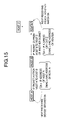
- FIG. 15 is a sequence diagram showing a network for explaining the feature of an IP packet to be sent to a host connected to a network outside the subnetwork;
- FIG. 16 is a flowchart showing a second example of a router detection operation of a router detection section 26 in the first embodiment
- FIG. 17 is a block diagram showing a network information detection device according to a second embodiment of the present invention.
- FIGS. 18A and 18B are sequence diagrams showing a first example of a subnet mask checking method in the second embodiment
- FIG. 19 is a flowchart showing the first example of the subnet mask checking operation in the second embodiment
- FIGS. 20A and 20B are sequence diagrams showing a second example of subnet mask checking method in the second embodiment
- FIG. 21 is a flowchart showing the second example of the subnet mask checking operation in the second embodiment
- FIGS. 22A and 22B are sequence diagrams showing a third example of subnet mask checking method in the second embodiment
- FIG. 23 is a flowchart showing the third example of the subnet mask checking operation in the second embodiment.
- FIGS. 24A and 24B are sequence diagrams showing a fourth example of subnet mask checking method in the second embodiment
- FIG. 25 is a flowchart showing the fourth example of the subnet mask checking operation in the second embodiment.
- FIG. 26 is a block diagram showing a network information detection device according to a third embodiment of the present invention.
- a local area network (LAN) 10 is composed of a plurality of network devices such as a network information detection device 20 , host computers 30 - 50 , and a router 60 .
- the network information detection device 20 uses IP packets and/or ARP (Address Resolution Protocol) packets to perform subnet mask detection, IP address determination, router detection and network information settings.
- ARP Address Resolution Protocol
- the network information detection device 20 is provided with a network interface section 21 which is used for connection to the LAN 10 .
- the network interface section 21 is connected to a packet monitor 23 , a subnet mask detection section 24 , an IP address determination section 25 , a router detection section 26 , and a network information sending section 28 to send and receive IP packets or ARP packets to and from the LAN 10 .
- the network interface section 21 passes all packets on the LAN 10 to the packet monitor 23 .
- the packet monitor 23 is connected to the subnet mask detection section 24 to monitor IP packets or ARP packets received from the network interface section 21 .
- the subnet mask detection section 24 , the IP address determination section 25 , the router detection section 26 , and the network information sending section 28 are connected to a network information setting section 27 .
- the entire operation of the network information detection device 20 is controlled by a controller 22 .
- a packet flowing on the LAN 10 is a data-link-layer packet having a format of FIG. 3 , an IP packet having a format of FIG. 4 , or an ARP packet having a format of FIG. 5 .
- the subnet mask detection section 24 analyzes IP or ARP packets monitored by the packet monitor 23 to detect subnet mask information of a host having source/destination IP address included in the monitored packet and/or determine the subnet, which will be described in detail by referring to FIGS. 8-12 .
- IP address For information, a general format of IP address is shown in FIG. 6 .
- the IP address determination section 25 detects an unallocated IP address based on the subnet mask detected by the subnet mask detection section 24 to determine an IP address to be allocated to the network information detection device 20 , which will be described in detail by referring to FIG. 13 .
- the router detection section 26 detects the router 60 by determining whether the IP packet monitored by the packet monitor 23 has the feature of an IP packet sent to the router 60 , which will be described in detail by referring to FIGS. 14-15 .
- the router detection section 26 sends an ICMP echo request as shown in FIG. 7A to each IP address of the subnet detected by the subnet mask detection section 24 and detects the router 60 by receiving an ICMP time exceed message as shown in FIG. 7B or an ICMP redirect message as shown in FIG. 7C , which will be described in detail by referring to FIG. 16 .
- the network information setting section 27 receives network information composed of at least one of the subnet mask detected by the subnet mask detection section 24 , the unallocated IP address detected by the IP address determination section 25 , and the router IP address detected by the router detection section 26 . Thereafter, the network information setting section 27 sets the received network information into the device 20 or outputs it to the network information sending section 28 to send it to another network device through the LAN 10 so that the other network device can make use of the network information.
- the packet monitor 23 monitors ARP or IP packets for a preset time period under control of the controller 22 (step S 2401 ). As shown in FIG. 3 , the packet monitor 23 determines the type of a received packet such that it is an ARP packet when the type of Ethernet header indicates 0x806 and an IP packet when 0x800. When at least one ARP/IP packet has been monitored for the preset time period (YES in step S 2402 ), the packet monitor 23 passes the monitored packet to the subnet mask detection section 24 . If neither ARP nor IP packet has been never monitored (NO in step S 2402 ), control goes back to the step S 2401 .
- the subnet mask detection section 24 reads the source IP address and destination IP address from at least one IP packet (see FIG. 4 ) or ARP packet (see FIG. 5 ) received from the packet monitor 23 and takes Max_IP as the maximum one of the read source and destination IP addresses (step S 2403 ) and Min_IP as the minimum one thereof (step S 2404 ).
- the subnet mask detection section 24 compares the Max_IP and Min_IP bit by bit to determine the high end bit of host section having a different value between Max_IP and Min_IP (step S 2405 )
- a subnet mask can be determined by one's complement of a 32-bit value obtained by setting the digits between the high end bit and the least significant bit to 1 and resetting the remaining digits to 0 (step S 2406 ).
- the low-order 8 bits are “00000101” for the Max_IP and “00000011” for the Min_IP. Since the Max_IP and Min_IP have the same high-order 24 bits, the high end bit of a different value between them is underlined bit 2 which is the last but two. Therefore, the high end bit of the host section in subnet is bit 2 .
- bit 2 By resetting all bits higher than the high end bit (bit 2 ) and setting all bits from bit 2 - 0 , a 32-bit value “0.0.0.7” is obtained.
- the subnet mask detection operation will be described taking as an example the case where four ARP/IP packets are monitored.
- the IP region A corresponds to a subnet.
- the Min_IP of the IP region A is the minimum IP address of the packet No. 1 and the Max_IP of the region A is the maximum IP address of the packet No. 4.
- the packet monitor 23 monitors ARP or IP packets for a preset time period under control of the controller 22 (step S 2411 ).
- the packet monitor 23 passes the monitored packet to the subnet mask detection section 24 . If two or more ARP/IP packets have been never monitored (NO in step S 2412 ), control goes back to the step S 2411 .
- the subnet mask detection section 24 detects an IP region determined by the source IP address and the destination IP address for each of monitored packets (step S 2413 ), and further detects overlapping IP regions (steps S 2414 -S 2416 ).
- step S 2414 it is determined whether the following determination conditions are satisfied for arbitrary two IP regions A and B: MINa ⁇ MAXb, and, MAXa ⁇ MINb (step S 2414 ). When the conditions are satisfied (YES in step S 2414 ), the IP regions A and B are combined into a single IP region (step S 2415 ).
- the overlapping region detection steps S 2414 -S 2416 are repeatedly performed for combinations of all IP regions.
- Max_IP is set to the maximum IP address of at least one finally detected IP region (step S 2417 ) and Min_IP is set to the minimum IP address thereof (step S 2418 ).
- the subnet mask detection section 24 compares the Max_IP and Min_IP bit by bit to determine the high end bit of host section having a different value between Max_IP and Min_IP (step S 2419 ).
- a subnet mask can be determined by one's complement of a 32-bit value obtained by setting the digits between the high end bit and the least significant bit to 1 and resetting the remaining digits to 0 (step S 2420 ).
- the above steps S 2417 -S 2420 are repeatedly performed until the subnet mask detection operation has been performed for all IP regions (NO in step S 2421 ).
- the subnet mask detection section 24 uses the detected subnet mask to determine that subnets having the same value in network and subnet are identical to each other (step S 2422 ).
- the subnet mask detection section 24 determines that the individual IP regions of the packets Nos. 2-4 are combined into a signal IP region C because their IP regions continuously overlap. Therefore, based on the monitored four packets, the subnet mask detection section 24 determines that the IP region B and the IP region C correspond to individual subnets.
- the Min_IP and the Max_IP of the IP region B are the minimum IP address and the maximum IP address of the packet No. 1, respectively.
- the Min_IP of the IP region C is the minimum IP address of the packet No. 2 and the Max_IP of the IP region C is the maximum IP address of the packet No. 4.
- the packet monitor 23 monitors ARP or IP packets under control of the controller 22 (step S 2441 ).
- the packet monitor 23 passes the monitored packet to the subnet mask detection section 24 .
- the subnet mask detection section 24 reads the source IP address or destination IP address from the IP packet monitored by the packet monitor 23 , takes Monitor_IP as the read IP address, takes Check_IP as the Monitor_IP, sets Bit_Copunter to zero (step S 2442 ). Thereafter, the subnet mask detection section 24 performs a logical OR of the Check_IP and the Set_Bit to store the result into the Check_IP, increments the Bit_Counter by one, and shifts the Set_Bit left by one bit (step S 2443 ).
- the subnet mask detection section 24 generates an ICMP echo request (see FIG. 7A ) having the Check_IP as its source IP address and the Monitor_IP as its destination IP address and sends it to the LAN 10 through the network interface section 21 (step S 2444 ).
- the subnet mask detection section 24 determines whether an ICMP echo reply (see FIG. 7A ) having no broadcast address as its destination MAC address of Ethernet header (step S 2445 ). When a received ICMP echo reply has no broadcast address as its destination MAC address (YES in step S 2445 ), it is determined that the Check_IP can communicate with Monitor_IP on Network layer without using Broadcast address as MAC address, and the control goes back to the step S 2443 .
- step S 2445 when an ICMP echo reply has no broadcast address as its destination MAC address has never been received (NO in step S 2445 ), the subnet mask detection section 24 determines that the Check_IP cannot communicate with Monitor_IP on Network layer without using Broadcast address as MAC address, and decrements the Bit_Counter by one before setting Bit_Num A to the resultant Bit_Counter (step S 2446 ), sets the Bit_Counter to 0, and sets Reset_Bit to 1 (step S 2447 ).
- the subnet mask detection section 24 performs a logical AND of the Check_IP and one's complement of the Reset_Bit to store the result into the Check_IP, increments the Bit_Counter by one, and shifts the Reset_Bit left by one bit (step S 2448 ).
- the subnet mask detection section 24 generates an ICMP echo request (see FIG. 7A ) having the Check_IP as its source IP address and the Monitor_IP as its destination IP address and sends it to the LAN 10 through the network interface section 21 (step S 2449 ).
- the subnet mask detection section 24 determines whether an ICMP echo reply having no broadcast address as its destination MAC address of Ethernet header (step S 2450 ). When a received ICMP echo reply has no broadcast address as its destination MAC address (YES in step S 2450 ), it is determined that the Check_IP can communicate with Monitor_IP on Network layer without using Broadcast address as MAC address, and the control goes back to the step S 2448 .
- the subnet mask detection section 24 determines that the Check_IP cannot communicate with Monitor_IP on Network layer without using Broadcast address as MAC address, decrements the Bit_Counter by one before setting Bit_Num B to the resultant Bit_Counter (step S 2451 ), and uses the Bit_Num B as the high end bit number in Host section of Subnet (step S 2452 ).
- the subnet mask detection section 24 determines whether the Bit_Num A is greater than the Bit_Num B (step S 2453 ).
- Bit_Num A>Bit_NumB YES in step S 2453
- the Bit_Num A is used as the high end bit number in Host section of Subnet (step S 2454 ) before performing the step S 2455 .
- the step S 2455 is performed without performing the step S 2454 .
- the steps S 2455 performs one's complement of a 32-bit value obtained by setting the digits between the high end bit and the least significant bit to 1 and resetting the remaining digits to 0 to produce a subset mask.
- check IP addresses are sequentially generated based on a monitor IP address to check whether communication between the generated check IP address and the monitor IP address is allowed without using broadcast address as MAC address and determines a subnet region depending on whether such communication is possible.
- the subnet mask detection will be described with reference to FIG. 12 , taking as an example the case where check IP addresses Nos. 1-4 are generated based on source or destination IP address of a monitored ARP/IP address.
- check IP addresses No. 1 and No. 2 are adjacent to each other and check IP addresses No. 3 and No. 4 are adjacent to each other.
- an ICMP echo reply having no broadcast address as MAC address is sent from the monitor IP address back to each of check IP addresses Nos. 2 and 3 and therefore the network-layer communication as described above is possible, which is labeled with “Comm.OK”.
- such an ICMP echo reply is not sent back to each of check IP addresses Nos. 1 and 4 and therefore the network-layer communication as described above is impossible, which is labeled with “Comm.NG”.
- each of the check IP addresses Nos. 1 and 4 is the maximum or minimum IP address in the subnet, that is, the broadcast address, which cannot be assigned to any network device.
- the network-layer communication without using broadcast address as MAC address is possible between the monitor IP address and the check IP addresses Nos. 2 and 3 and impossible between the monitor IP address and the check IP addresses Nos. 1 and 4, which means that the ICMP echo communication cannot be also made without using broadcast address as MAC address.
- the subnet ranges between the check IP addresses No. 1 and No. 4.
- the IP address determination section 25 determines IP addresses which are allocable within the subnet.
- the IP address determination section 25 sets Check_IP to the minimum IP address of the subnet (step S 2591 ) and increments the Check_IP by one (step S 2592 ).
- the IP address determination section 25 determines whether the Check_IP is equal to the maximum IP address of the subnet (step S 2593 ). When Check_IP is equal to the subnet max IP (YES in step S 2593 ), it is determined that no IP address is allocable and then the process is terminated. When the Check_IP is not equal to the maximum IP address of the subnet (NO in step S 2593 ), the IP address determination section 25 generates an ARP request having the Check_IP as a target IP address and sends it to the LAN 10 through the network interface section 21 (step S 2594 ).
- the IP address determination section 25 determines whether an ARP reply to the ART request has been received within a preset time period (step S 2595 ).
- the ARP reply has been received (YES in step S 2595 )
- it is determined that the Check_IP is an IP address that has been already allocated to some network device and therefore the control goes back to the step S 2592 so that a subsequent IP address is checked.
- the Check_IP is an IP address that is not allocated to any network device and therefore the IP address determination section 25 determines that this Check_IP is an allocable IP address (step S 2596 ).
- the router detection section 26 determines whether the monitored IP address belongs to another network outside the subnet (step S 2682 ). When the monitored IP address is inside the subnet (NO in step S 2682 ), the control goes back to the step S 2681 . The determination whether the monitored IP address is outside the subnet will be described later.
- the router detection section 26 sets a MAC address of a router (Router_MAC) to the destination MAC address of the monitored IP packet (step S 2683 ) and sends an InARP (Inverse Address Resolution Protocol) request having the Router_MAC as its target hardware address to the LAN 10 through the network interface section 21 (step S 2684 ).
- Router_MAC MAC address of a router
- InARP Inverse Address Resolution Protocol
- the router detection section 26 determines whether an InARP reply to the InARP request is received within a preset time period (step S 2685 ) When no InARP reply has been received (NO in step S 2685 ), the control goes back to the step S 2681 .
- an InARP reply to the InARP request has been received within the preset time period (YES in step S 2685 )
- it is determined that the IP address of a router is the source protocol address included in the received InARP reply packet (step S 2686 ) and the process is terminated.
- the IP address of a router in the subnet can be identified by monitoring an IP packet sent to outside the subnet.
- the feature of such an IP packet sent to outside the subnet will be described with reference to FIG. 15 .
- the destination IP address of the IP packet (1) is the same as the IP address of the host A that will directly receive the IP packet (1) from the host B.
- the destination IP address of the IP packet (2) is the IP address of the host Z, which is different from the IP address of the router that will directly receive the IP packet (2) from the host B. Accordingly, it is determined that the destination IP address of the IP packet (2) is outside the subnet and the MAC address of the router is the destination MAC address of the IP packet (2). In this manner, the IP address of the router can be detected based on the InARP request/reply process.
- the router detection section 26 sets Check_IP to the minimum IP address of the subnet (step S 2691 ) and increments the Check_IP by one (step S 2692 ).
- the router detection section 26 determines whether the Check_IP is equal to the maximum IP address of the subnet (step S 2693 ). When Check_IP is equal to the subnet max IP (YES in step S 2693 ), it is determined that no router exists in the subnet and then the process is terminated.
- the router detection section 26 When the Check_IP is not equal to the maximum IP address of the subnet (NO in step S 2693 ), the router detection section 26 generates an ICMP echo request having its destination IP address set to the Check_IP and TTL (Time To Live) set to a predetermined value and sends it to the LAN 10 through the network interface section 21 (step S 2694 ).
- TTL is set to 2, which means that the ICMP echo request packet is permitted to pass through up to two routers.
- the router detection section 26 determines that the router IP address is the router IP address included in the ICMP redirect message packet (step S 2698 ) and the router detection operation is terminated. In this manner, the IP address of a router can be detected.
- the subnet mask detection, the IP address detection and the router detection are performed to detect the network information including the subnet, allocable IP address and router IP address.
- the network information detected like these are output to the network information setting section 27 .
- the network information detection device 20 As shown in FIG. 17 , the network information detection device 20 according to a second embodiment is different from the first embodiment of FIG. 2 in that the second embodiment is further provided with a subnet mask check section 29 . Therefore, blocks similar to those previously described with reference to FIG. 2 are denoted by the same reference numerals 21 - 28 and the details thereof will be omitted.
- FIGS. 18A and 18B it is assumed for simplicity that a network device which performs comparison of subnet mask values is denoted by “Device 1 ” and another network device which is to be compared is denoted by “Device 2 ”.
- Device 1 sends Device 2 an ICMP echo request having its source IP address set to an IP address obtained by setting the host section of the IP address of Device 1 or 2 to 0 (all bits are 0s) or ⁇ 1 (all bits are 1s), which will be described in detail later.
- Device 2 sends an ICMP echo reply back to Device 1 by unicast.
- Device 2 does not send any ICMP echo reply back to Device 1 by unicast or replies to the ICMP echo request by broadcast.
- Device 1 When no ICMP echo reply has been received by unicast, as shown in FIG. 18B , Device 1 sends Device 2 an ICMP echo request having its source IP address set to an IP address obtained by inverting each bit for Host of the IP address of Device 2 , which will be described in detail later.
- Device 2 When the subnet mask of Device 1 is equal to that of Device 2 , Device 2 sends an ICMP echo reply back to Device 1 by unicast.
- the subnet mask of Device 1 When the subnet mask of Device 1 is smaller than that of Device 2 , Device 2 does not send any ICMP echo reply back to Device 1 .
- the subnet mask check operation is performed by the subnet mask check section 29 .
- Device 1 and Device 2 of FIGS. 18A and 18B correspond to “its own device” and “device using monitored IP address”, respectively.
- the packet monitor 23 monitors packets on the LAN 10 (step S 3001 ) and determines whether the monitored packet is an ARP packet under control of the controller 22 (step S 3002 ). When it is not an ARP packet (NO in step S 3002 ), it is further determined whether it is an IP packet (step S 3003 ). If it is not an IP packet (NO in step S 3003 ), the control goes back to the step S 3001 .
- the subnet mask check section 29 produces an ARP request having its source IP address set to the IP address of its own device and its destination IP address set to the monitored I address and sends it to the LAN 10 (step S 3004 ), and then waits for replies.
- step S 3005 When no ARP reply to the ARP request has been received within a preset time period (NO in step S 3005 ), it is determined that the monitored IP address is located outside the LAN 10 and then the control goes back to the step S 3001 .
- the subnet mask check section 29 determines that the monitored IP address is located within the LAN 10 and then determines whether the network address (Network+Subnet) of the monitored IP address is equal to that of its own device (step S 3006 ). When the network address of the monitored IP address is not equal to that of its own device (NO in step S 3006 ), the check operation is terminated.
- the subnet mask check section 29 produces an ICMP echo request having its source IP address obtained by setting the host section of the IP address of its own device or the monitored IP address to 0 or ⁇ 1 and its destination IP address set to the monitored IP address, and sends it to the LAN 10 (step S 3007 )
- setting Host to 0 is to set all bits for Host to 0, which is performed when the least significant bit (LSB) of the network address of the IP address of its own device is 1.
- Setting Host to ⁇ 1 is to set all bits for Host to 1, which is performed when LSB of the network address of the IP address of its own device is 0.
- the source IP address of the ICMP echo request is set to “10.56.88.255”.
- the source IP address of the ICMP echo request is set to “10.56.89.0”.
- the subnet mask check section 29 determines whether any ICMP echo reply is received by unicast from the device having the monitored IP address allocated thereto (step S 3008 ).
- the subnet mask check section 29 produces an ICMP echo request having its source IP address obtained by inverting each bit of the host section of the monitored IP address and its destination IP address set to the monitored IP address, and sends it to the LAN 10 (step S 3009 ).
- the source IP address of the ICMP echo request is obtained by inverting at least MSB of the host section of the monitored IP address with the remaining bits set to an arbitrary value other than 0 or ⁇ 1.
- the source IP address of the ICMP echo request is set to an arbitrary value ranging between “10.56.88.254” and “10.56.88.128”.
- the subnet mask check section 29 determines whether any ICMP echo reply is received by unicast from the device having the monitored IP address allocated thereto (step S 3010 ).
- the subnet mask check section 29 determines that the subnet mask value of its own device is smaller than that of the monitored IP address allocated device (step S 3011 ) and the process is terminated.
- the subnet mask check section 29 determines that the subnet mask value of its own device is equal to that of the monitored IP address allocated device (step S 3013 ) and the process is terminated.
- the subnet mask check section 29 determines that the subnet mask value of its own device is greater than that of the monitored IP address allocated device (step S 3012 ) and the process is terminated.
- the controller 22 controls the subnet mask detection section 24 , the IP address determination section 25 , and the router detection section 26 so as to selectively perform or re-execute, as necessary, detections of a desired subnet mask, an allocable IP address and a router IP address, transfer of these network information to the network information setting section 27 , transfer of the network information from the network information setting section 27 to the network information sending section 28 , and transfer of the network information from the network information sending section 28 to the network interface section 21 .
- a network device when it is determined that a network device has a different subnet mask or a different network address, such a network device may be notified of erroneous setting of subnet mask or network address by communication means such as e-mail. In such a case, necessary network information may be sent to the network device through the network information sending section 28 so as to automatically perform the setting of a correct network address or subnet mask.
- FIGS. 20A and 20B it is assumed for simplicity that a network device which performs comparison of subnet mask values is denoted by “Device 1 ” and another network device which is to be compared is denoted by “Device 2 ”.
- Device 1 sends Device 2 an ICMP echo request having its source IP address set to an IP address obtained by inverting each bit for Host of the IP address of Device 2 , which will be described in detail later.
- Device 2 sends an ICMP echo reply back to Device 1 by unicast.
- Device 2 does not send any ICMP echo reply back to Device 1 .
- Device 1 sends Device 2 an ICMP echo request having its source IP address set to an IP address obtained by setting the host section of the IP address of Device 1 or 2 to 0 (all bits are 0s) or ⁇ 1 (all bits are 1s), which will be described in detail later.
- the subnet mask of Device 1 is greater than that of Device 2
- Device 2 sends an ICMP echo reply back to Device 1 by unicast.
- the subnet mask of Device 1 is equal to that of Device 2
- Device 2 does not send any ICMP echo reply back to Device 1 by unicast or replies to the ICMP echo request by broadcast.
- the subnet mask check operation is performed by the subnet mask check section 29 .
- Device 1 and Device 2 of FIGS. 18A and 18B correspond to “its own device” and “device using monitored IP address”, respectively. Since the steps S 4001 -S 4006 of FIG. 21 are the same as the steps S 3001 -S 3006 of FIG. 19 , their details will be omitted.
- the subnet mask check section 29 produces an ICMP echo request having its source IP address obtained by inverting each bit of the host section of the monitored IP address and its destination IP address set to the monitored IP address, and sends it to the LAN 10 (step S 4007 ).
- the source IP address of the ICMP echo request is obtained by inverting at least MSB of the host section of the monitored IP address with the remaining bits set to an arbitrary value other than 0 or ⁇ 1.
- the source IP address of the ICMP echo request is set to an arbitrary value ranging between “10.56.88.254” and “10.56.88.128”.
- the subnet mask check section 29 determines whether any ICMP echo reply is received by unicast from the device having the monitored IP address allocated thereto (step S 4008 ).
- the subnet mask check section 29 produces an ICMP echo request having its source IP address obtained by setting the host section of the IP address of its own device or the monitored IP address to 0 or ⁇ 1 and its destination IP address set to the monitored IP address, and sends it to the LAN 10 (step S 4009 ).
- setting Host to 0 is to set all bits for Host to 0, which is performed when the least significant bit (LSB) of the network address of the IP address of its own device is 1.
- Setting Host to ⁇ 1 is to set all bits for Host to 1, which is performed when LSB of the network address of the IP address of its own device is 0.
- the subnet mask check section 29 determines whether any ICMP echo reply is received by unicast from the device having the monitored IP address allocated thereto (step S 4010 ).
- the subnet mask check section 29 determines that the subnet mask value of its own device is greater than that of the monitored IP address allocated device (step S 4011 ) and the process is terminated.
- the subnet mask check section 29 determines that the subnet mask value of its own device is equal to that of the monitored IP address allocated device (step S 4013 ) and the process is terminated.
- the subnet mask check section 29 determines that the subnet mask value of its own device is smaller than that of the monitored IP address allocated device (step S 4012 ) and the process is terminated.
- the controller 22 controls the subnet mask detection section 24 , the IP address determination section 25 , and the router detection section 26 so as to selectively perform or re-execute, as necessary, detections of a desired subnet mask, an allocable IP address and a router IP address, transfer of these network information to the network information setting section 27 , transfer of the network information from the network information setting section 27 to the network information sending section 28 , and transfer of the network information from the network information sending section 28 to the network interface section 21 .
- a network device when it is determined that a network device has a different subnet mask or a different network address, such a network device may be notified of erroneous setting of subnet mask or network address by communication means such as e-mail. In such a case, necessary network information may be sent to the network device through the network information sending section 28 so as to automatically perform the setting of a correct network address or subnet mask.
- FIGS. 22A and 22B it is assumed for simplicity that a network device which performs comparison of subnet mask values is denoted by “Device 1 ” and another network device which is to be compared is denoted by “Device 2 ”.
- Device 1 sends Device 2 an ICMP echo request having its source IP address set to an IP address obtained by inverting each bit for Host of the IP address of Device 2 , which will be described in detail later.
- Device 2 sends an ICMP echo reply back to Device 1 by unicast.
- Device 2 does not send any ICMP echo reply back to Device 1 .
- Device 1 sends Device 2 an ICMP echo request having its source IP address set to an IP address obtained by inverting the least significant bit (LSB) of the network address of Device 1 or 2 .
- LSB least significant bit
- Device 2 sends an ICMP echo reply back to Device 1 by unicast.
- the subnet mask of Device 1 is equal to that of Device 2 , Device 2 does not send any ICMP echo reply back to Device 1 by unicast.
- the subnet mask check operation is performed by the subnet mask check section 29 .
- Device 1 and Device 2 of FIGS. 22A and 22B correspond to “its own device” and “device using monitored IP address”, respectively. Since the steps S 5001 -S 5006 of FIG. 23 are the same as the steps S 3001 -S 3006 of FIG. 19 , their details will be omitted.
- the subnet mask check section 29 produces an ICMP echo request having its source IP address obtained by inverting each bit of the host section of the monitored IP address and its destination IP address set to the monitored IP address, and sends it to the LAN 10 (step S 5007 ).
- the source IP address of the ICMP echo request is obtained by inverting at least MSB of the host section of the monitored IP address with the remaining bits set to an arbitrary value other than 0 or ⁇ 1.
- the source IP address of the ICMP echo request is set to an arbitrary value ranging between “10.56.88.254” and “10.56.88.128”.
- the subnet mask check section 29 determines whether any ICMP echo reply is received by unicast from the device having the monitored IP address allocated thereto (step S 5008 ).
- the subnet mask check section 29 produces an ICMP echo request having its source IP address obtained by inverting the LSB of the network address specified by the subnet mask of its own device in the IP address of its own device or the monitored IP address and its destination IP address set to the monitored IP address, and sends it to the LAN 10 (step S 5009 ).
- the subnet mask check section 29 determines whether any ICMP echo reply is received by unicast from the device having the monitored IP address allocated thereto (step S 5010 ).
- the subnet mask check section 29 determines that the subnet mask value of its own device is greater than that of the monitored IP address allocated device (step S 5011 ) and the process is terminated.
- the subnet mask check section 29 determines that the subnet mask value of its own device is equal to that of the monitored IP address allocated device (step S 5013 ) and the process is terminated.
- the subnet mask check section 29 determines that the subnet mask value of its own device is smaller than that of the monitored IP address allocated device (step S 5012 ) and the process is terminated.
- the controller 22 controls the subnet mask detection section 24 , the IP address determination section 25 , and the router detection section 26 so as to selectively perform or re-execute, as necessary, detections of a desired subnet mask, an allocable IP address and a router IP address, transfer of these network information to the network information setting section 27 , transfer of the network information from the network information setting section 27 to the network information sending section 28 , and transfer of the network information from the network information sending section 28 to the network interface section 21 .
- a network device when it is determined that a network device has a different subnet mask or a different network address, such a network device may be notified of erroneous setting of subnet mask or network address by communication means such as e-mail. In such a case, necessary network information may be sent to the network device through the network information sending section 28 so as to automatically perform the setting of a correct network address or subnet mask.
- FIGS. 24A and 24B it is assumed for simplicity that a network device which performs comparison of subnet mask values is denoted by “Device 1 ” and another network device which is to be compared is denoted by “Device 2 ”.
- Device 1 sends Device 2 an ICMP echo request having its source IP address set to an IP address obtained by inverting the least significant bit (LSB) of the network address of Device 1 or 2 .
- LSB least significant bit
- Device 1 sends Device 2 an ICMP echo request having its source IP address set to an IP address obtained by inverting each bit for Host of the IP address of Device 2 .
- Device 2 sends an ICMP echo reply back to Device 1 by unicast.
- the subnet mask of Device 1 is smaller than that of Device 2 , Device 2 does not send any ICMP echo reply back to Device 1 .
- the subnet mask check operation is performed by the subnet mask check section 29 .
- Device 1 and Device 2 of FIGS. 24A and 24B correspond to “its own device” and “device using monitored IP address”, respectively. Since the steps S 6001 -S 6006 of FIG. 25 are the same as the steps S 3001 -S 3006 of FIG. 19 , their details will be omitted.
- the subnet mask check section 29 produces an ICMP echo request having its source IP address obtained by inverting the LSB of the network address specified by the subnet mask of its own device in the IP address of its own device or the monitored IP address and its destination IP address set to the monitored IP address, and sends it to the LAN 10 (step S 6007 ).
- the subnet mask check section 29 determines whether any ICMP echo reply is received by unicast from the device having the monitored IP address allocated thereto (step S 6008 ).
- the subnet mask check section 29 produces an ICMP echo request having its source IP address obtained by inverting each bit of the host section of the monitored IP address and its destination IP address set to the monitored IP address, and sends it to the LAN 10 (step S 6009 ).
- the source IP address of the ICMP echo request is obtained by inverting at least MSB of the host section of the monitored IP address with the remaining bits set to an arbitrary value other than 0 or ⁇ 1.
- the source IP address of the ICMP echo request is set to an arbitrary value ranging between “10.56.88.254” and “10.56.88.128”.
- the subnet mask check section 29 determines whether any ICMP echo reply is received by unicast from the device having the monitored IP address allocated thereto (step S 6010 ).
- the subnet mask check section 29 determines that the subnet mask value of its own device is equal to that of the monitored IP address allocated device (step S 6011 ) and the process is terminated.
- the subnet mask check section 29 determines that the subnet mask value of its own device is smaller than that of the monitored IP address allocated device (step S 6013 ) and the process is terminated.
- the subnet mask check section 29 determines that the subnet mask value of its own device is greater than that of the monitored IP address allocated device (step S 6012 ) and the process is terminated.
- the controller 22 controls the subnet mask detection section 24 , the IP address determination section 25 , and the router detection section 26 so as to selectively perform or re-execute, as necessary, detections of a desired subnet mask, an allocable IP address and a router IP address, transfer of these network information to the network information setting section 27 , transfer of the network information from the network information setting section 27 to the network information sending section 28 , and transfer of the network information from the network information sending section 28 to the network interface section 21 .
- a network device when it is determined that a network device has a different subnet mask or a different network address, such a network device may be notified of erroneous setting of subnet mask or network address by communication means such as e-mail. In such a case, necessary network information may be sent to the network device through the network information sending section 28 so as to automatically perform the setting of a correct network address or subnet mask.
- the network information detection device 20 is provided with a network interface 201 for connecting to the network 10 and a communication controller 202 for sending and receiving IP or ARP packets as described before.
- a program-controlled processor 203 controls the above-described processing of detection, determination and setting of network information by executing subnet mask detection program, IP address determination program, router detection program and subnet mask check program which are read from a program memory 204 .
- the network information detected as described above is stored in a network information memory 205 and is installed onto its own device or is sent to another network device on the network 10 so that the network information be set to the other network device.
- the network information detected as described above is not limited to the above-described items and, as necessary, any desired function may be implemented in the network information detection device. Only one of the IP address determination section and the network information sending section may be implemented in the network information detection device.
Abstract
Description
Claims (34)
Applications Claiming Priority (4)
| Application Number | Priority Date | Filing Date | Title |
|---|---|---|---|
| JP2002-191717 | 2002-07-01 | ||
| JP2002191717 | 2002-07-01 | ||
| JP2003180537A JP4232550B2 (en) | 2002-07-01 | 2003-06-25 | Network information detection apparatus and method |
| JP2003-180537 | 2003-06-25 |
Publications (2)
| Publication Number | Publication Date |
|---|---|
| US20040017814A1 US20040017814A1 (en) | 2004-01-29 |
| US7724679B2 true US7724679B2 (en) | 2010-05-25 |
Family
ID=30772201
Family Applications (1)
| Application Number | Title | Priority Date | Filing Date |
|---|---|---|---|
| US10/609,591 Active 2027-09-08 US7724679B2 (en) | 2002-07-01 | 2003-07-01 | Device and method for automatically detecting network information |
Country Status (2)
| Country | Link |
|---|---|
| US (1) | US7724679B2 (en) |
| JP (1) | JP4232550B2 (en) |
Cited By (3)
| Publication number | Priority date | Publication date | Assignee | Title |
|---|---|---|---|---|
| US20070280244A1 (en) * | 2006-06-05 | 2007-12-06 | Fujitsu Limited | Management device to investigate path states of network and network system |
| US20080301811A1 (en) * | 2006-03-09 | 2008-12-04 | Sung Wook Jung | System For Stabilizing of Web Service and Method Thereof |
| US20170180305A1 (en) * | 2015-12-21 | 2017-06-22 | Verizon Deutschland Gmbh | Configuring a protocol address of a network device using an address resolution protocol request |
Families Citing this family (24)
| Publication number | Priority date | Publication date | Assignee | Title |
|---|---|---|---|---|
| US7614993B2 (en) * | 2001-07-20 | 2009-11-10 | Dixie Consumer Products Llc | Liquid container with uninterrupted comfort band and method of forming same |
| US7496659B1 (en) * | 2003-08-06 | 2009-02-24 | Cisco Technology, Inc. | Method and apparatus for monitoring the availability of network resources |
| US7424004B2 (en) * | 2004-06-28 | 2008-09-09 | Intel Corporation | Systems and methods for networking passive information devices |
| US7649834B2 (en) * | 2004-09-15 | 2010-01-19 | At&T Intellectual Property Ii, L.P. | Method and apparatus for determining neighboring routing elements and rerouting traffic in a computer network |
| JP2006094416A (en) * | 2004-09-27 | 2006-04-06 | Nec Corp | Subscriber's line accommodation apparatus and packet filtering method |
| JP4499526B2 (en) * | 2004-10-19 | 2010-07-07 | 富士通株式会社 | Data transmission path establishment system between mobile phone terminals |
| US8510833B2 (en) * | 2005-10-27 | 2013-08-13 | Hewlett-Packard Development Company, L.P. | Connection-rate filtering using ARP requests |
| JP4682056B2 (en) * | 2006-02-17 | 2011-05-11 | 株式会社リコー | Device management apparatus, device management system, device management method, device search program, and recording medium |
| JP4681472B2 (en) * | 2006-02-24 | 2011-05-11 | 富士通株式会社 | Topology information collection program, topology information collection device, and topology information collection method |
| WO2007114035A1 (en) * | 2006-03-30 | 2007-10-11 | Matsushita Electric Industrial Co., Ltd. | Connection support server and communication apparatus |
| US8027271B2 (en) * | 2006-05-30 | 2011-09-27 | Panasonic Corporation | Communicating apparatus and controlling method of thereof |
| JP5012207B2 (en) * | 2006-05-30 | 2012-08-29 | パナソニック株式会社 | COMMUNICATION DEVICE, COMMUNICATION DEVICE CONTROL METHOD, AND COMMUNICATION DEVICE CONTROL PROGRAM |
| US8107396B1 (en) * | 2006-07-24 | 2012-01-31 | Cisco Technology, Inc. | Host tracking in a layer 2 IP ethernet network |
| TW200826562A (en) * | 2006-12-01 | 2008-06-16 | Inst Information Industry | Data transmission system for dynamically adjusting PDU length, method thereof, and readable-by-computer recording medium |
| US7848271B2 (en) | 2007-06-26 | 2010-12-07 | Research In Motion Limited | System and method for conserving power for a wireless device while maintaining a connection to a network |
| JP5115561B2 (en) * | 2008-01-17 | 2013-01-09 | 日本電気株式会社 | Wireless communication terminal, method, program, recording medium, and wireless communication system |
| JP4809880B2 (en) * | 2008-09-09 | 2011-11-09 | 日本電信電話株式会社 | Network topology estimation system, network topology estimation method and recording medium |
| US10659734B2 (en) * | 2009-06-29 | 2020-05-19 | Ideal Industries, Inc. | Handheld communications devices and communications methods |
| JP5501052B2 (en) * | 2010-03-24 | 2014-05-21 | キヤノン株式会社 | COMMUNICATION DEVICE, COMMUNICATION DEVICE CONTROL METHOD, PROGRAM |
| US9313085B2 (en) | 2010-12-16 | 2016-04-12 | Microsoft Technology Licensing, Llc | DNS-based determining whether a device is inside a network |
| US8949411B2 (en) | 2010-12-16 | 2015-02-03 | Microsoft Corporation | Determining whether a device is inside a network |
| US10015162B2 (en) * | 2015-05-11 | 2018-07-03 | Huawei Technologies Co., Ltd. | Firewall authentication of controller-generated internet control message protocol (ICMP) echo requests |
| CN111224815B (en) * | 2019-11-22 | 2023-04-18 | 山东英信计算机技术有限公司 | Data center equipment access method, device and related components |
| KR20230031714A (en) * | 2021-08-27 | 2023-03-07 | 삼성전자주식회사 | A display apparatus, an electronic apparatus and a method of the same |
Citations (13)
| Publication number | Priority date | Publication date | Assignee | Title |
|---|---|---|---|---|
| JPH08223169A (en) | 1995-02-13 | 1996-08-30 | Nec Miyagi Ltd | Method for automatically setting tcp/ip host address and device therefor |
| US5835710A (en) * | 1994-08-31 | 1998-11-10 | Kabushiki Kaisha Toshiba | Network interconnection apparatus, network node apparatus, and packet transfer method for high speed, large capacity inter-network communication |
| JPH10336228A (en) | 1997-05-28 | 1998-12-18 | Hitachi Cable Ltd | Router and network management equipment |
| JPH11187057A (en) | 1997-12-19 | 1999-07-09 | Hitachi Cable Ltd | Repeating hub and network management device |
| US6292838B1 (en) | 1999-08-23 | 2001-09-18 | 3Com Corporation | Technique for automatic remote media access control (MAC) layer address resolution |
| US6345294B1 (en) | 1999-04-19 | 2002-02-05 | Cisco Technology, Inc. | Methods and apparatus for remote configuration of an appliance on a network |
| US20020032773A1 (en) * | 2000-07-31 | 2002-03-14 | Servgate Technology, Inc. | System, method and computer software products for network firewall fast policy look-up |
| JP2002190811A (en) | 2000-09-30 | 2002-07-05 | Fluke Networks Inc | Device and method for automatically acquiring effective ip configuration in local area network |
| US6532217B1 (en) * | 1998-06-29 | 2003-03-11 | Ip Dynamics, Inc. | System for automatically determining a network address |
| JP2003188900A (en) | 2001-12-18 | 2003-07-04 | Brother Ind Ltd | System, method and program for estimating address, and network device |
| US20030198219A1 (en) * | 2001-03-06 | 2003-10-23 | Robert Coggeshall | Contacting a computing device outside a local network |
| US7281036B1 (en) * | 1999-04-19 | 2007-10-09 | Cisco Technology, Inc. | Method and apparatus for automatic network address assignment |
| US7466703B1 (en) * | 1998-05-01 | 2008-12-16 | Alcatel-Lucent Usa Inc. | Scalable high speed router apparatus |
-
2003
- 2003-06-25 JP JP2003180537A patent/JP4232550B2/en not_active Expired - Fee Related
- 2003-07-01 US US10/609,591 patent/US7724679B2/en active Active
Patent Citations (14)
| Publication number | Priority date | Publication date | Assignee | Title |
|---|---|---|---|---|
| US5835710A (en) * | 1994-08-31 | 1998-11-10 | Kabushiki Kaisha Toshiba | Network interconnection apparatus, network node apparatus, and packet transfer method for high speed, large capacity inter-network communication |
| JPH08223169A (en) | 1995-02-13 | 1996-08-30 | Nec Miyagi Ltd | Method for automatically setting tcp/ip host address and device therefor |
| JPH10336228A (en) | 1997-05-28 | 1998-12-18 | Hitachi Cable Ltd | Router and network management equipment |
| JPH11187057A (en) | 1997-12-19 | 1999-07-09 | Hitachi Cable Ltd | Repeating hub and network management device |
| US7466703B1 (en) * | 1998-05-01 | 2008-12-16 | Alcatel-Lucent Usa Inc. | Scalable high speed router apparatus |
| US6532217B1 (en) * | 1998-06-29 | 2003-03-11 | Ip Dynamics, Inc. | System for automatically determining a network address |
| US6757723B1 (en) * | 1999-04-19 | 2004-06-29 | Cisco Technology, Inc. | Methods and apparatus for remote configuration of an appliance on a network |
| US6345294B1 (en) | 1999-04-19 | 2002-02-05 | Cisco Technology, Inc. | Methods and apparatus for remote configuration of an appliance on a network |
| US7281036B1 (en) * | 1999-04-19 | 2007-10-09 | Cisco Technology, Inc. | Method and apparatus for automatic network address assignment |
| US6292838B1 (en) | 1999-08-23 | 2001-09-18 | 3Com Corporation | Technique for automatic remote media access control (MAC) layer address resolution |
| US20020032773A1 (en) * | 2000-07-31 | 2002-03-14 | Servgate Technology, Inc. | System, method and computer software products for network firewall fast policy look-up |
| JP2002190811A (en) | 2000-09-30 | 2002-07-05 | Fluke Networks Inc | Device and method for automatically acquiring effective ip configuration in local area network |
| US20030198219A1 (en) * | 2001-03-06 | 2003-10-23 | Robert Coggeshall | Contacting a computing device outside a local network |
| JP2003188900A (en) | 2001-12-18 | 2003-07-04 | Brother Ind Ltd | System, method and program for estimating address, and network device |
Cited By (5)
| Publication number | Priority date | Publication date | Assignee | Title |
|---|---|---|---|---|
| US20080301811A1 (en) * | 2006-03-09 | 2008-12-04 | Sung Wook Jung | System For Stabilizing of Web Service and Method Thereof |
| US20070280244A1 (en) * | 2006-06-05 | 2007-12-06 | Fujitsu Limited | Management device to investigate path states of network and network system |
| US8254388B2 (en) | 2006-06-05 | 2012-08-28 | Fujitsu Limited | Management device to investigate path states of network and network system |
| US20170180305A1 (en) * | 2015-12-21 | 2017-06-22 | Verizon Deutschland Gmbh | Configuring a protocol address of a network device using an address resolution protocol request |
| US10432575B2 (en) * | 2015-12-21 | 2019-10-01 | Verizon Patent And Licensing Inc. | Configuring a protocol address of a network device using an address resolution protocol request |
Also Published As
| Publication number | Publication date |
|---|---|
| US20040017814A1 (en) | 2004-01-29 |
| JP4232550B2 (en) | 2009-03-04 |
| JP2004088747A (en) | 2004-03-18 |
Similar Documents
| Publication | Publication Date | Title |
|---|---|---|
| US7724679B2 (en) | Device and method for automatically detecting network information | |
| EP0943202B1 (en) | Method and apparatus for assignment of ip addresses | |
| US7436783B2 (en) | Method and apparatus for detecting a router that improperly responds to ARP requests | |
| US6925079B2 (en) | IP address duplication detection method using address resolution protocol | |
| US5708654A (en) | Method for detecting proxy ARP replies from devices in a local area network | |
| US5922049A (en) | Method for using DHCP and marking to override learned IP addesseses in a network | |
| US6542510B1 (en) | Network communication system | |
| EP2051446B1 (en) | Method of resolving duplicate mac addresses, network device managing system, server, and information device | |
| US20120304294A1 (en) | Network Monitoring Apparatus and Network Monitoring Method | |
| US7480250B2 (en) | Apparatus and method for establishing network | |
| US11418444B2 (en) | IPv6 network node managing method and equipment | |
| US7530100B2 (en) | Apparatus for limiting use of particular network address | |
| US7636791B2 (en) | Network information detection apparatus and method | |
| US6751697B1 (en) | Method and system for a multi-phase net refresh on a bus bridge interconnect | |
| US7613123B2 (en) | Apparatus and method for establishing network | |
| JPH08223206A (en) | Automatic address assignment system | |
| US20060056313A1 (en) | Method for automatic network integration of a network | |
| WO2015196719A1 (en) | Address configuration method, apparatus and device | |
| JP7376289B2 (en) | Address monitoring device and address monitoring method | |
| JP3892235B2 (en) | Automatic address assignment method | |
| JP7444600B2 (en) | Detection device and detection method | |
| JP7417395B2 (en) | Fraud detection device and fraud detection method | |
| JP7359586B2 (en) | Address management device and address management method | |
| US20050135364A1 (en) | Communication method and apparatus using multicast address | |
| JP2004266546A (en) | Communication device, communication control method and communication control program |
Legal Events
| Date | Code | Title | Description |
|---|---|---|---|
| AS | Assignment |
Owner name: NEC CORPORATION, JAPAN Free format text: ASSIGNMENT OF ASSIGNORS INTEREST;ASSIGNOR:SHIMADA, MASAO;REEL/FRAME:014260/0487 Effective date: 20030624 Owner name: NEC CORPORATION,JAPAN Free format text: ASSIGNMENT OF ASSIGNORS INTEREST;ASSIGNOR:SHIMADA, MASAO;REEL/FRAME:014260/0487 Effective date: 20030624 |
|
| STCF | Information on status: patent grant |
Free format text: PATENTED CASE |
|
| FPAY | Fee payment |
Year of fee payment: 4 |
|
| MAFP | Maintenance fee payment |
Free format text: PAYMENT OF MAINTENANCE FEE, 8TH YEAR, LARGE ENTITY (ORIGINAL EVENT CODE: M1552) Year of fee payment: 8 |
|
| MAFP | Maintenance fee payment |
Free format text: PAYMENT OF MAINTENANCE FEE, 12TH YEAR, LARGE ENTITY (ORIGINAL EVENT CODE: M1553); ENTITY STATUS OF PATENT OWNER: LARGE ENTITY Year of fee payment: 12 |