US7722358B2 - Electrical connection between devices - Google Patents
Electrical connection between devices Download PDFInfo
- Publication number
- US7722358B2 US7722358B2 US11/763,951 US76395107A US7722358B2 US 7722358 B2 US7722358 B2 US 7722358B2 US 76395107 A US76395107 A US 76395107A US 7722358 B2 US7722358 B2 US 7722358B2
- Authority
- US
- United States
- Prior art keywords
- magnetic
- input device
- pins
- connector
- magnet
- Prior art date
- Legal status (The legal status is an assumption and is not a legal conclusion. Google has not performed a legal analysis and makes no representation as to the accuracy of the status listed.)
- Expired - Fee Related, expires
Links
Images


Classifications
-
- G—PHYSICS
- G06—COMPUTING; CALCULATING OR COUNTING
- G06F—ELECTRIC DIGITAL DATA PROCESSING
- G06F1/00—Details not covered by groups G06F3/00 - G06F13/00 and G06F21/00
- G06F1/16—Constructional details or arrangements
-
- G—PHYSICS
- G06—COMPUTING; CALCULATING OR COUNTING
- G06F—ELECTRIC DIGITAL DATA PROCESSING
- G06F1/00—Details not covered by groups G06F3/00 - G06F13/00 and G06F21/00
- G06F1/26—Power supply means, e.g. regulation thereof
-
- G—PHYSICS
- G06—COMPUTING; CALCULATING OR COUNTING
- G06F—ELECTRIC DIGITAL DATA PROCESSING
- G06F13/00—Interconnection of, or transfer of information or other signals between, memories, input/output devices or central processing units
- G06F13/14—Handling requests for interconnection or transfer
-
- G—PHYSICS
- G06—COMPUTING; CALCULATING OR COUNTING
- G06F—ELECTRIC DIGITAL DATA PROCESSING
- G06F3/00—Input arrangements for transferring data to be processed into a form capable of being handled by the computer; Output arrangements for transferring data from processing unit to output unit, e.g. interface arrangements
- G06F3/01—Input arrangements or combined input and output arrangements for interaction between user and computer
- G06F3/03—Arrangements for converting the position or the displacement of a member into a coded form
- G06F3/033—Pointing devices displaced or positioned by the user, e.g. mice, trackballs, pens or joysticks; Accessories therefor
- G06F3/0354—Pointing devices displaced or positioned by the user, e.g. mice, trackballs, pens or joysticks; Accessories therefor with detection of 2D relative movements between the device, or an operating part thereof, and a plane or surface, e.g. 2D mice, trackballs, pens or pucks
- G06F3/03543—Mice or pucks
-
- G—PHYSICS
- G06—COMPUTING; CALCULATING OR COUNTING
- G06F—ELECTRIC DIGITAL DATA PROCESSING
- G06F3/00—Input arrangements for transferring data to be processed into a form capable of being handled by the computer; Output arrangements for transferring data from processing unit to output unit, e.g. interface arrangements
- G06F3/01—Input arrangements or combined input and output arrangements for interaction between user and computer
- G06F3/03—Arrangements for converting the position or the displacement of a member into a coded form
- G06F3/033—Pointing devices displaced or positioned by the user, e.g. mice, trackballs, pens or joysticks; Accessories therefor
- G06F3/038—Control and interface arrangements therefor, e.g. drivers or device-embedded control circuitry
- G06F3/0383—Signal control means within the pointing device
-
- H—ELECTRICITY
- H01—ELECTRIC ELEMENTS
- H01R—ELECTRICALLY-CONDUCTIVE CONNECTIONS; STRUCTURAL ASSOCIATIONS OF A PLURALITY OF MUTUALLY-INSULATED ELECTRICAL CONNECTING ELEMENTS; COUPLING DEVICES; CURRENT COLLECTORS
- H01R13/00—Details of coupling devices of the kinds covered by groups H01R12/70 or H01R24/00 - H01R33/00
- H01R13/62—Means for facilitating engagement or disengagement of coupling parts or for holding them in engagement
- H01R13/6205—Two-part coupling devices held in engagement by a magnet
-
- H—ELECTRICITY
- H02—GENERATION; CONVERSION OR DISTRIBUTION OF ELECTRIC POWER
- H02J—CIRCUIT ARRANGEMENTS OR SYSTEMS FOR SUPPLYING OR DISTRIBUTING ELECTRIC POWER; SYSTEMS FOR STORING ELECTRIC ENERGY
- H02J50/00—Circuit arrangements or systems for wireless supply or distribution of electric power
- H02J50/10—Circuit arrangements or systems for wireless supply or distribution of electric power using inductive coupling
Definitions
- computing systems such as personal computers, hand-held or laptop devices, multi-processor systems, set top boxes, network PCs, mini computers, and the like typically receive input from a user via a device such as a keyboard and/or a mouse.
- a device such as a keyboard and/or a mouse.
- These types of input devices can be attached to a processing unit of the computing systems by a wired connection. Signals generated by operations such as pressing an actuable switch on a mouse are provided via the wired connection so that the computing device can process the inputs provided by a user.
- an input device in another situation, includes data stored in memory that is transferred to a computing system.
- These devices can include watches, mobile devices, personal digital assistants, cellular telephones and cameras.
- the data can be transferred via a wired connection to the computing system such that the data can be stored and/or manipulated by the computing system. If desired, the computing system can transmit electrical signals to these devices for purposes of synchronization.
- input devices may include a rechargeable power store for powering the input devices.
- the internal power store located within the devices has a finite amount of energy stored therein. When the devices are unconnected to any type of external device under normal operation, normal usage of the devices will dissipate the energy stored within the power supply. Eventually, it may be necessary to replenish or recharge the power store in order for a user to continue to use the devices.
- Electrical power and data signals can be supplied by a first device through a cord to a second device.
- the cord can be adapted to form a magnetic coupling with the first device and/or the second device.
- transfer of electrical power and data signals between the devices can be provided.
- one of the devices can be adapted to transmit wireless signals to the other device and remain in operation while coupled to the cord.
- FIG. 1 is an isometric view of an electrical connection system.
- FIG. 2 is a block diagram of components in an electrical connection system.
- FIG. 3 is an isometric view of a dongle.
- FIG. 4 is an isometric view of a cord.
- FIG. 5 is a schematic view of a magnetic coupling between a dongle and a cord.
- FIG. 6 is an isometric bottom view of an input device.
- FIG. 7 is a schematic view of a magnetic coupling between a cord and an input device.
- FIG. 8 is an isometric bottom view of an input device having a cord attached thereto.
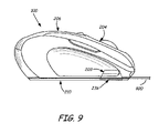
- FIG. 9 is a side view of an input device having a cord attached thereto.
- FIG. 1 is an isometric view of an input device 100 that interfaces with a computer 102 , which also operates as a charging and/or communication device for input device 100 .
- Input device 100 includes several components for interfacing with computer 102 to perform various tasks.
- Input device 100 is illustrated as a mouse, although other input devices can also be used such as game controllers, keyboards, scanners, sensors, watches, cameras, personal digital assistants, cellular telephones, etc. and any other devices that can receive and/or transmit input as well as receive power from computer 102 .
- computer 102 is illustrated as a laptop computer although other devices used for communication with and/or charging input device 100 , such as, but not limited to desktop computers, mobile devices, personal digital assistants, cellular telephones, memory storage units, etc.
- Input device 100 can communicate wirelessly through a transceiver dongle 104 that is directly coupled to computer 102 .
- transceiver dongle 104 can be adapted to transmit power from computer 102 to input device 100 through a cord 106 .
- transceiver dongle 104 can transfer electrical power (i.e. energy) to input device 100 in order to recharge a power store within input device 100 .
- signals can be transferred from input device 100 to computer 102 through cord 106 .
- computer 102 can be configured to transmit signals to input device 102 .
- device 100 and cord 106 are configured to allow operation of input device 100 as in normal operation.
- cord 106 can be positioned within a recess provided in input device 100 such that cord 106 moves therewith and a position of device 100 can still be sensed by a sensor within input device 100 and transmitted to transceiver dongle 104 .
- computer 102 can be adapted to provide an indicator such as an icon displayed thereon that indicates electrical power and/or signals are being transferred between input device 100 and computer 102 .
- the input device 100 can also then be configured to operate in a wired mode such that actuation of components of the input device 100 are sent to computer 102 through cord 106 .
- a transceiver to communicate wirelessly with input device 100 can be an internal component of computer 102 .
- a connector for receiving cord 106 can be integrated into a form factor of computer 102 , as desired.
- FIG. 2 provides a more detailed diagram of internal components illustrated in FIG. 1 .
- input device 100 includes a processing module 200 coupled to a power store 202 , which is adapted to provide power to the processing module 200 .
- power store 202 includes a rechargeable battery and is coupled to a connector 203 to receive power provided through cord 106 .
- Input device 100 also includes a set of keys 204 positioned on a top surface 206 of input device 100 and a position tracking sensor 208 positioned on a bottom surface 210 of input device 100 .
- the positioning of keys 204 and position tracking sensor 208 is illustrative only, and can be positioned in several locations as desired.
- Keys 204 can be any form of input mechanism such as buttons, wheels, balls, switches, pads, etc that can be actuated by a user. Upon actuation of any of the keys 204 , processing module 200 provides a signal indicative thereof to a transceiver 214 .
- Transceiver 214 can be any type of wireless communication module that transmits signals to transceiver dongle 104 that is directly coupled to computer 102 .
- transceiver 214 is a Bluetooth® compatible transceiver for wirelessly transmitting signals to and receiving signals from transceiver dongle 104 .
- Other types of transceivers that can be used include 2.4 GHz transceivers, 27 MHz transceivers and wireless USB transceivers.
- Position tracking sensor 208 can be any type of tracking sensor such as a track ball, optical sensor, etc. Relative movements of input device 100 or a portion thereof correspond to movements of a cursor in a plane as detected by position tracking sensor 208 .
- Transceiver 214 can send a signal indicative of movement sensed by position tracking sensor 208 to transceiver dongle 104 . For example, when surface 210 is positioned on a flat surface such as a table top, sensor 208 tracks the position of device 100 on the table top. If sensor 208 is a track ball sensor, movement of the track ball relative to a device housing is sensed to provide the position.
- Transceiver dongle 104 includes a connector 216 that is adapted to be coupled to a corresponding connector 218 on an input device interface 220 of computer 102 .
- Input device interface 220 receives signals from input device 100 , in particular from transceiver dongle 104 that are received from transceiver 214 .
- Computer 102 also includes a processing unit 222 , memory 224 and a video interface 226 .
- Memory 224 can include one or more applications, such as applications 228 A-B.
- video interface 226 is coupled to a monitor 230 to display images thereon. By operating input device 100 , a user can interact with any of the applications 228 A-B for display on monitor 230 .
- cord 106 can be coupled to transceiver dongle 104 and input device 100 .
- Transceiver dongle 104 includes a connector 232 that mates with a corresponding connector 234 provided on cord 106 .
- Cord 106 also includes second connector 236 that interfaces with connector 203 on input device 100 .
- electrical power transmission can be provided to recharge power store 202 .
- transfer of electrical signals can be provided between input device 100 and computer 102 .
- Connector 203 is recessed from surface 210 to allow connector 236 to be connected thereto such that connector 236 can be flush with or recessed from surface 210 .
- signals sent by transceiver 114 can instead be sent via cord 106 , for example when wireless communication between input device 100 and computer 102 is prohibited.
- FIG. 3 is an isometric view of transceiver dongle 104 .
- Transceiver dongle 104 includes a housing 300 with connectors 216 and 232 positioned on either end of the housing.
- Housing 300 includes transceiver circuitry positioned therein that is adapted to communicate wirelessly with transceiver 214 of input device 100 .
- housing 300 includes electrical wiring adapted to transfer electrical power and signals from connector 216 to connector 232 .
- connector 216 is a Universal Serial Bus (USB) connector, although other types of connections can be used.
- USB Universal Serial Bus
- Connector 232 includes a plurality of electrical interface elements, herein connector pins 304 A, 304 B and 304 C. These connector pins 304 A- 304 C are adapted to interface with corresponding pins on connector 234 of cord 106 to form an electrical connection from connector 216 through wires in housing 300 and to connector 234 .
- Connector 232 also includes a magnet 306 adapted to attract a corresponding magnet on connector 234 and a cup-shaped recess 308 extending inwardly from housing 300 to receive an outwardly extending protrusion from connector 234 of cord 106 .
- Cup-shaped recess 308 includes a central rectangular recessed surface surrounded by four beveled surfaces adjacent thereto.
- the beveled surfaces aid in forming a cup shape to receive connector 234 .
- the cup-shaped recess 308 can be asymmetrical to aid a person in aligning connector 234 with connector 232 .
- one of the beveled surfaces can be longer than a beveled surface on the opposite side of the recess 308 to provide a physical guide for aligning connector 232 with connector 234 .
- FIG. 4 is an isometric view of cord 106 , which includes an elongated cable 400 extending between connectors 234 and 236 .
- Connector 234 includes a housing 402 , a plurality of interface elements, herein connector pins 404 A, 404 B and 404 C that are adapted to be coupled to pins 304 A, 304 B and 304 C, respectively, of connector 232 .
- connector 234 includes a magnet 406 and an outwardly extending protrusion 408 .
- Protrusion 408 includes a central rectangular protruding surface with four beveled surfaces adjacent thereto. The beveled surfaces are configured to mate with corresponding surfaces in recess 308 of connector 232 . As such, these beveled surfaces can also be asymmetrical to match the surfaces of recess 308 .
- Connector 236 includes a housing 410 with connector pins 412 A, 412 B and 412 C and includes a magnet 414 .
- Housing 410 is disc shaped and adapted to fit within a recess in input device 100 .
- Connector pins 404 A-C are electrically coupled to connector pins 412 A-C, respectively, through wires provided within cable 400 .
- FIG. 5 is a schematic view of a magnetic coupling 500 between connector 232 of transceiver dongle 104 and connector 234 of cord 106 .
- cup-shaped recess 308 of transceiver dongle 104 is aligned to mate with protrusion 408 of connector 234 .
- surfaces 308 A, 308 B and 308 C of recess 308 are adapted to mate with surfaces 408 A, 408 B and 408 C of protrusion 408 .
- one of the beveled surfaces of recess 308 and a corresponding surface of protrusion 408 can be of a different length and/or angle than the other beveled surfaces of recess 308 and protrusions 408 .
- both surfaces 308 A and 408 A can be of a longer length and a different angle than surface 308 C and 408 C, respectively.
- This asymmetric arrangement can provide a more visual alignment mechanism for a user when connecting connectors 232 and 234 .
- connectors 232 and 234 can include other mechanisms to aid in aligning and connecting pins 304 A- 304 C with pins 404 A- 404 C.
- pins 304 A- 304 C include concave end portions 501 to receive convex end portions 502 of pins 404 A- 404 C.
- a magnetic coupling is also used to secure connectors 232 and 234 together and form an electrical connection from transceiver dongle 104 to cord 106 .
- Magnetizing pins 304 A-C and 404 A-C with magnetic forces having opposite polarization can aid in ensuring that pins 304 A-C and 404 A-C are attracted and drawn towards each other and in a proper orientation. Additionally, the magnetization of the pins can resist being separated once they are engaged.
- Magnet 306 includes a magnetic orientation where North is in a direction toward pin 304 A and magnet 406 includes a magnetic orientation where North faces away from pin 404 A.
- magnetization of pin 304 A can be oriented in a direction where a North pole is proximate recess 308 and magnetization of pin 404 A is oriented in a direction where a South pole is proximate protrusion 408 .
- Pins 304 B and 304 C will be oriented in a magnetic direction opposite of pin 304 A such that pins 304 B-C include a South pole proximate recess 308 .
- pins 404 B and 404 C will be oriented in a magnetic direction opposite of pin 404 A such that pins 404 B-C include a North pole proximate protrusion 408 .
- pins 304 A-C and 404 A-C When brought in close proximity and in proper alignment, pins 304 A-C and 404 A-C will be brought into contact due to the magnetic force of the pins as well as magnets 306 and 406 . When in an improper alignment, magnetization of the pins and magnets 306 and 406 will repel connection of the pins. While connected, convex end portions 502 of pins 404 A-C are secured in concave portions 501 of pins 304 A-C, respectively. The North pole of pin 304 A is aligned with and connected to the South pole of pin 404 A. Likewise, the South poles of pins 304 B-C are aligned with and connected to the North poles of pins 404 B-C, respectively.
- Pins 304 A-C and 404 A-C can be drill rods that are formed of a ferrous material such as steel and have copper plating near end portions 501 and 502 .
- FIG. 6 is an isometric view of bottom surface 210 of input device 100 .
- Bottom surface 210 includes a connector receiving portion 600 that includes a connector recess 602 and a cable recess 604 .
- Connector recess 602 receives connector 236 and cable recess 604 receives cable 400 such that connector 236 and cable 400 can be flush with or recessed from surface 210 so as to not interfere with positioning of device 100 .
- connector 203 is illustrated that includes electrical interface elements, herein connector pins 606 A, 606 B and 606 C that connect to pins 412 A, 412 B and 412 C of connector 236 , respectively.
- Pins 606 A-C are electrically coupled to power store 202 within device 100 .
- Connector 203 also includes a magnet 608 to aid in forming a magnetic coupling with magnet 414 of connector 236 .
- FIG. 7 is a schematic view of a magnetic coupling 700 between connector 203 of input device 100 and connector 236 of cord 106 .
- a user can position input device 100 over connector 236 such that housing 410 can enter recess 602 and cable 400 can enter recess 604 .
- pins 606 A-C include convex end portions 701 that are received by concave end portions 702 of pins 412 A-C.
- magnetic forces can bring pins 412 A-C in contact with pins 606 A-C, respectively.
- magnetic forces will repel connection between connectors 203 and 236 .
- magnetic orientation of magnet 414 is in an opposite orientation from magnet 608 .
- Magnet 414 has a magnetic North orientation in a direction away from pin 412 A and toward pins 412 B-C. This orientation causes pin 412 A to have a South pole facing connector 203 while pins 412 B-C have North poles facing connector 203 .
- Magnet 608 is used to magnetically orient pins 606 A-C as well. Magnet 608 has a North orientation in a direction toward pin 606 A, causing pin 606 A to have a North pole facing connector 236 and pins 606 B-C having South poles facing connector 236 . Magnetic forces in the pins cause connection of connectors 203 and 236 such that end portions 701 are disposed in end portions 702 . Thus, an electrical connection is formed between pins 412 A-C and pins 606 A-C, respectively.
- FIG. 8 illustrates a bottom view of cord 106 connected to device 100
- FIG. 9 illustrates a side view of cord 106 connected to device 100 . While connected, cord 106 is flush or recessed from surface 210 of device 100 to allow cord 106 to move with device 100 . Thus, a user can operate device 100 while keys 204 and position tracking sensor 208 remain operational.
Abstract
Description
Claims (20)
Priority Applications (9)
| Application Number | Priority Date | Filing Date | Title |
|---|---|---|---|
| US11/763,951 US7722358B2 (en) | 2007-06-15 | 2007-06-15 | Electrical connection between devices |
| KR1020097023537A KR20100020941A (en) | 2007-06-15 | 2008-06-05 | Electrical connection between devices |
| JP2010512276A JP4644313B2 (en) | 2007-06-15 | 2008-06-05 | Electrical connection between devices |
| PCT/US2008/065915 WO2008157062A2 (en) | 2007-06-15 | 2008-06-05 | Electrical connection between devices |
| CN200880020143A CN101681186A (en) | 2007-06-15 | 2008-06-05 | Electrical connection between the equipment |
| CA002687229A CA2687229A1 (en) | 2007-06-15 | 2008-06-05 | Electrical connection between devices |
| EP08770196.7A EP2158534A4 (en) | 2007-06-15 | 2008-06-05 | Electrical connection between devices |
| US12/757,219 US8138717B2 (en) | 2007-06-15 | 2010-04-09 | Electrical connection between devices |
| US13/367,541 US20120135613A1 (en) | 2007-06-15 | 2012-02-07 | Electrical connection between devices |
Applications Claiming Priority (1)
| Application Number | Priority Date | Filing Date | Title |
|---|---|---|---|
| US11/763,951 US7722358B2 (en) | 2007-06-15 | 2007-06-15 | Electrical connection between devices |
Related Child Applications (1)
| Application Number | Title | Priority Date | Filing Date |
|---|---|---|---|
| US12/757,219 Continuation US8138717B2 (en) | 2007-06-15 | 2010-04-09 | Electrical connection between devices |
Publications (2)
| Publication Number | Publication Date |
|---|---|
| US20080311765A1 US20080311765A1 (en) | 2008-12-18 |
| US7722358B2 true US7722358B2 (en) | 2010-05-25 |
Family
ID=40132754
Family Applications (3)
| Application Number | Title | Priority Date | Filing Date |
|---|---|---|---|
| US11/763,951 Expired - Fee Related US7722358B2 (en) | 2007-06-15 | 2007-06-15 | Electrical connection between devices |
| US12/757,219 Expired - Fee Related US8138717B2 (en) | 2007-06-15 | 2010-04-09 | Electrical connection between devices |
| US13/367,541 Abandoned US20120135613A1 (en) | 2007-06-15 | 2012-02-07 | Electrical connection between devices |
Family Applications After (2)
| Application Number | Title | Priority Date | Filing Date |
|---|---|---|---|
| US12/757,219 Expired - Fee Related US8138717B2 (en) | 2007-06-15 | 2010-04-09 | Electrical connection between devices |
| US13/367,541 Abandoned US20120135613A1 (en) | 2007-06-15 | 2012-02-07 | Electrical connection between devices |
Country Status (7)
| Country | Link |
|---|---|
| US (3) | US7722358B2 (en) |
| EP (1) | EP2158534A4 (en) |
| JP (1) | JP4644313B2 (en) |
| KR (1) | KR20100020941A (en) |
| CN (1) | CN101681186A (en) |
| CA (1) | CA2687229A1 (en) |
| WO (1) | WO2008157062A2 (en) |
Cited By (31)
| Publication number | Priority date | Publication date | Assignee | Title |
|---|---|---|---|---|
| US20120148195A1 (en) * | 2010-12-09 | 2012-06-14 | Microsoft Corporation | Power and data connector |
| US8272876B2 (en) * | 2010-07-20 | 2012-09-25 | Magnetic Innovations, L.L.C. | Magnetically enhanced electrical signal conduction apparatus and methods |
| US20120329293A1 (en) * | 2011-06-23 | 2012-12-27 | K. S. Terminals Inc. | Magnetic connection cable |
| US20140180280A1 (en) * | 2012-12-20 | 2014-06-26 | Cook Medical Technologies Llc | Magnetic activation of monopolar and bipolar devices |
| US20140204514A1 (en) * | 2012-03-02 | 2014-07-24 | Microsoft Corporation | Flexible Hinge and Removable Attachment |
| US20140220793A1 (en) * | 2013-02-04 | 2014-08-07 | Kingston Digital, Inc. | Connecting device and electronic device assembly |
| US20140287601A1 (en) * | 2013-03-22 | 2014-09-25 | Samsung Electronics Co., Ltd. | Magnetic connection device |
| US9130291B2 (en) | 2012-08-29 | 2015-09-08 | Hewlett-Packard Development Company, Lp. | Device connector including magnet |
| US20150277508A1 (en) * | 2014-03-28 | 2015-10-01 | Microsoft Corporation | Mechanical Attach and Retention Feature |
| US20150346793A1 (en) * | 2014-06-03 | 2015-12-03 | Inventec (Pudong) Technology Corporation | Selective assembling type computing device |
| US9268373B2 (en) | 2012-03-02 | 2016-02-23 | Microsoft Technology Licensing, Llc | Flexible hinge spine |
| US9298236B2 (en) | 2012-03-02 | 2016-03-29 | Microsoft Technology Licensing, Llc | Multi-stage power adapter configured to provide a first power level upon initial connection of the power adapter to the host device and a second power level thereafter upon notification from the host device to the power adapter |
| US9300081B2 (en) | 2010-02-02 | 2016-03-29 | Charles Albert Rudisill | Interposer connectors with magnetic components |
| US9304549B2 (en) | 2013-03-28 | 2016-04-05 | Microsoft Technology Licensing, Llc | Hinge mechanism for rotatable component attachment |
| US20160141809A1 (en) * | 2014-11-18 | 2016-05-19 | Samsung Electronics Co., Ltd. | Electrical connector and electronic device including the same |
| US9348605B2 (en) | 2012-05-14 | 2016-05-24 | Microsoft Technology Licensing, Llc | System and method for accessory device architecture that passes human interface device (HID) data via intermediate processor |
| US9360893B2 (en) | 2012-03-02 | 2016-06-07 | Microsoft Technology Licensing, Llc | Input device writing surface |
| US20160191771A1 (en) * | 2012-10-04 | 2016-06-30 | Cognex Corporation | Component Attachment Devices and Related Systems and Methods for Machine Vision Systems |
| US20160211889A1 (en) * | 2013-09-30 | 2016-07-21 | Apple Inc. | Stackable, magnetically-retained connector interface |
| US9407034B2 (en) | 2007-09-14 | 2016-08-02 | Panasonic Avionics Corporation | Communication connector system and method |
| US9426905B2 (en) | 2012-03-02 | 2016-08-23 | Microsoft Technology Licensing, Llc | Connection device for computing devices |
| US9631691B2 (en) | 2013-06-28 | 2017-04-25 | Magnetic Innovations Llc | Vibration dampening devices and methods |
| US9793073B2 (en) | 2012-03-02 | 2017-10-17 | Microsoft Technology Licensing, Llc | Backlighting a fabric enclosure of a flexible cover |
| US9870066B2 (en) | 2012-03-02 | 2018-01-16 | Microsoft Technology Licensing, Llc | Method of manufacturing an input device |
| US10031556B2 (en) | 2012-06-08 | 2018-07-24 | Microsoft Technology Licensing, Llc | User experience adaptation |
| US20200076138A1 (en) * | 2018-09-05 | 2020-03-05 | Assa Abloy Ab | Systems and devices for authentication |
| US10680383B2 (en) | 2013-03-14 | 2020-06-09 | Apex Technologies, Inc. | Linear electrode systems for module attachment with non-uniform axial spacing |
| US20220029320A1 (en) * | 2018-11-28 | 2022-01-27 | Fujikura Ltd. | Cable and image transmission system |
| USRE48963E1 (en) | 2012-03-02 | 2022-03-08 | Microsoft Technology Licensing, Llc | Connection device for computing devices |
| US11322253B2 (en) * | 2019-12-08 | 2022-05-03 | Modo Medical Design Llc | Wireless sensor connectivity |
| US20230144303A1 (en) * | 2021-11-11 | 2023-05-11 | Onanon, Inc. | Electromagnetic Electrical Connector System |
Families Citing this family (74)
| Publication number | Priority date | Publication date | Assignee | Title |
|---|---|---|---|---|
| CN101802766A (en) * | 2007-09-14 | 2010-08-11 | 松下航空电子公司 | Media device interface system and method for vehicle information systems |
| US7997914B2 (en) * | 2008-06-11 | 2011-08-16 | Google Inc. | Push-to-insert, push-to-eject and pull-to-extract card connector |
| US8410622B1 (en) * | 2008-08-06 | 2013-04-02 | Christopher S. Wallach | Vertical axis wind turbine with computer controlled wings |
| US8554136B2 (en) | 2008-12-23 | 2013-10-08 | Waveconnex, Inc. | Tightly-coupled near-field communication-link connector-replacement chips |
| US9322904B2 (en) | 2011-06-15 | 2016-04-26 | Keyssa, Inc. | Proximity sensing using EHF signals |
| US9407311B2 (en) | 2011-10-21 | 2016-08-02 | Keyssa, Inc. | Contactless signal splicing using an extremely high frequency (EHF) communication link |
| CN101943956A (en) * | 2009-07-08 | 2011-01-12 | 深圳富泰宏精密工业有限公司 | Multifunctional mouse |
| US8742814B2 (en) | 2009-07-15 | 2014-06-03 | Yehuda Binder | Sequentially operated modules |
| US8602833B2 (en) | 2009-08-06 | 2013-12-10 | May Patents Ltd. | Puzzle with conductive path |
| CN102947769B (en) * | 2010-06-07 | 2016-09-21 | 慧与发展有限责任合伙企业 | Module and port |
| NO20101208A1 (en) * | 2010-08-31 | 2012-03-01 | Kibano As | Magnetically removable removable electronic devices |
| WO2012034111A1 (en) | 2010-09-10 | 2012-03-15 | Panasonic Avionics Corporation | Integrated user interface system and method |
| US8838868B2 (en) * | 2010-12-17 | 2014-09-16 | Qualcomm Incorporated | Communication port and connector |
| EP2469663B1 (en) * | 2010-12-24 | 2020-06-17 | Phitek Systems Limited | Magnetic connector apparatus |
| US8298084B2 (en) | 2011-02-03 | 2012-10-30 | Edmond Yee | Multi-player game controller system with combinable hand-held game controllers |
| US8879748B2 (en) | 2011-03-15 | 2014-11-04 | Microsoft Corporation | Multi-protocol wireless audio client device |
| WO2012129426A2 (en) | 2011-03-24 | 2012-09-27 | Waveconnex, Inc. | Integrated circuit with electromagnetic communication |
| US8811526B2 (en) | 2011-05-31 | 2014-08-19 | Keyssa, Inc. | Delta modulated low power EHF communication link |
| GB201110019D0 (en) * | 2011-06-15 | 2011-07-27 | Optilume Ltd | Electrical connection means |
| EP2541367B1 (en) | 2011-06-30 | 2018-08-15 | BlackBerry Limited | Dock for a portable electronic device |
| US9019718B2 (en) | 2011-08-26 | 2015-04-28 | Littlebits Electronics Inc. | Modular electronic building systems with magnetic interconnections and methods of using the same |
| US9597607B2 (en) | 2011-08-26 | 2017-03-21 | Littlebits Electronics Inc. | Modular electronic building systems with magnetic interconnections and methods of using the same |
| US11330714B2 (en) | 2011-08-26 | 2022-05-10 | Sphero, Inc. | Modular electronic building systems with magnetic interconnections and methods of using the same |
| CN104145380B (en) * | 2011-12-14 | 2017-09-29 | 基萨公司 | The connector of touch feedback is provided |
| ES2618728T3 (en) * | 2012-01-30 | 2017-06-22 | Sensoria Inc. | Sensors, interfaces and sensor systems for data collection and integration of remote monitoring of nearby conditions or on body surfaces |
| WO2013131095A2 (en) | 2012-03-02 | 2013-09-06 | Waveconnex, Inc. | Systems and methods for duplex communication |
| EP2642611A1 (en) | 2012-03-19 | 2013-09-25 | Nigel Greig | Connector apparatus |
| GB201210361D0 (en) | 2012-06-12 | 2012-07-25 | Fugro Subsea Services Ltd | Apparatus and method |
| TWI595715B (en) | 2012-08-10 | 2017-08-11 | 奇沙公司 | Dielectric coupling systems for ehf communications |
| CN104769852B (en) | 2012-09-14 | 2016-09-21 | 凯萨股份有限公司 | There are the wireless connections of virtual magnetic hysteresis |
| KR20150098645A (en) | 2012-12-17 | 2015-08-28 | 키사, 아이엔씨. | Modular electronics |
| TWI525937B (en) * | 2012-12-21 | 2016-03-11 | 緯創資通股份有限公司 | Protection device for protecting a power cable connector and related power supply and electronic system |
| US20140210719A1 (en) * | 2013-01-28 | 2014-07-31 | Dexin Corporation | Wireless input device |
| CN103972935A (en) * | 2013-01-31 | 2014-08-06 | 凡甲电子(苏州)有限公司 | Controller and control method for electronic device charging system |
| CA2841685C (en) | 2013-03-15 | 2021-05-18 | Panasonic Avionics Corporation | System and method for providing multi-mode wireless data distribution |
| EP2974504B1 (en) | 2013-03-15 | 2018-06-20 | Keyssa, Inc. | Ehf secure communication device |
| EP2974057B1 (en) | 2013-03-15 | 2017-10-04 | Keyssa, Inc. | Extremely high frequency communication chip |
| US9912174B2 (en) * | 2013-05-10 | 2018-03-06 | Cynetic Designs Ltd. | Inductively coupled wireless power and data for a garment via a dongle |
| EP3065659A2 (en) * | 2013-11-08 | 2016-09-14 | Cook Medical Technologies LLC | Handle and power cord assemblies for bipolar electrosurgical devices |
| US20150246293A1 (en) * | 2014-02-28 | 2015-09-03 | Alexander Kokhan | Electrical construction toy system |
| EP3175514B1 (en) | 2014-07-31 | 2022-08-31 | Hewlett-Packard Development Company, L.P. | Dock connector |
| KR20160001560U (en) * | 2014-11-04 | 2016-05-12 | (주)에스피에스 | Portable storage device in which magnet is embedded |
| US10582891B2 (en) | 2015-03-23 | 2020-03-10 | Consensus Orthopedics, Inc. | System and methods for monitoring physical therapy and rehabilitation of joints |
| US11684260B2 (en) | 2015-03-23 | 2023-06-27 | Tracpatch Health, Inc. | System and methods with user interfaces for monitoring physical therapy and rehabilitation |
| EP3273846A1 (en) | 2015-03-23 | 2018-01-31 | Consensus Orthopedics, Inc | Joint sensor system and method of operation thereof |
| US11272879B2 (en) | 2015-03-23 | 2022-03-15 | Consensus Orthopedics, Inc. | Systems and methods using a wearable device for monitoring an orthopedic implant and rehabilitation |
| US9778705B2 (en) | 2015-09-04 | 2017-10-03 | Apple Inc. | Electronic device with moveable contacts at an exterior surface |
| US10579097B2 (en) * | 2015-09-04 | 2020-03-03 | Apple Inc. | Electronic device with contacts flush with housing |
| US9948018B2 (en) | 2015-09-08 | 2018-04-17 | Apple Inc. | Low-profile power and data contacts |
| US9363904B1 (en) * | 2015-12-18 | 2016-06-07 | Nanoport Technology Inc. | Adapters for adapting an electronic device to a modular electronic device system |
| KR20170088231A (en) * | 2016-01-22 | 2017-08-01 | (주)에스피에스 | Magnetic connecting device |
| US9852098B2 (en) * | 2016-02-26 | 2017-12-26 | Essential Products, Inc. | Systems and techniques for intelligently switching between multiple sources of universal serial bus signals |
| DE102017002146A1 (en) | 2016-03-04 | 2017-09-07 | Logitech Europe S.A. | Wireless charging for an input device |
| US20170256978A1 (en) * | 2016-03-04 | 2017-09-07 | Logitech Europe S.A. | Wireless charging for an input device |
| US10365493B2 (en) | 2016-12-23 | 2019-07-30 | Realwear, Incorporated | Modular components for a head-mounted display |
| US11507216B2 (en) | 2016-12-23 | 2022-11-22 | Realwear, Inc. | Customizing user interfaces of binary applications |
| US10936872B2 (en) | 2016-12-23 | 2021-03-02 | Realwear, Inc. | Hands-free contextually aware object interaction for wearable display |
| US10620910B2 (en) | 2016-12-23 | 2020-04-14 | Realwear, Inc. | Hands-free navigation of touch-based operating systems |
| US11099716B2 (en) | 2016-12-23 | 2021-08-24 | Realwear, Inc. | Context based content navigation for wearable display |
| US10437070B2 (en) | 2016-12-23 | 2019-10-08 | Realwear, Inc. | Interchangeable optics for a head-mounted display |
| US10393312B2 (en) | 2016-12-23 | 2019-08-27 | Realwear, Inc. | Articulating components for a head-mounted display |
| WO2018144715A1 (en) * | 2017-02-01 | 2018-08-09 | Consensus Orthopedics, Inc. | Systems and methods using a wearable device for monitoring an orthopedic implant and rehabilitation |
| GB201712312D0 (en) * | 2017-07-31 | 2017-09-13 | Ksg Global Consulting Ltd | Apparatus and method |
| CN111094881A (en) * | 2017-08-02 | 2020-05-01 | 双天收购有限责任公司 | System for providing in-transit power for active storage containers |
| US10707627B2 (en) | 2017-09-29 | 2020-07-07 | Apple Inc. | Hybrid connector |
| TWI650633B (en) * | 2017-10-06 | 2019-02-11 | 財團法人國家實驗研究院 | Modular electronic combination device |
| US11177673B1 (en) * | 2018-07-30 | 2021-11-16 | Frank Dale Boxberger | Electronic device charging apparatus that maintains proper electrical polarity to the device |
| US11616844B2 (en) | 2019-03-14 | 2023-03-28 | Sphero, Inc. | Modular electronic and digital building systems and methods of using the same |
| CN212725101U (en) * | 2019-09-20 | 2021-03-16 | 光宝电子(广州)有限公司 | Backlight keyboard |
| US10863928B1 (en) | 2020-01-28 | 2020-12-15 | Consensus Orthopedics, Inc. | System and methods for monitoring the spine, balance, gait, or posture of a patient |
| US11283215B2 (en) | 2020-07-13 | 2022-03-22 | Xerox Corporation | Magnetic connector system and method of using |
| TWI744076B (en) * | 2020-11-06 | 2021-10-21 | 寶德科技股份有限公司 | Mouse device |
| KR102512306B1 (en) * | 2021-02-22 | 2023-03-22 | 근로복지공단 | Mouse using electromyogram signal |
| CN113032308A (en) * | 2021-04-21 | 2021-06-25 | 立讯精密工业股份有限公司 | Multifunctional single-interface type electronic expansion equipment and external electronic expansion device |
Citations (20)
| Publication number | Priority date | Publication date | Assignee | Title |
|---|---|---|---|---|
| US3146049A (en) * | 1962-04-27 | 1964-08-25 | Clifford E Sloop | Electric by-pass assembly |
| KR980010692A (en) | 1996-01-19 | 1998-04-30 | 이데이 노브유끼 | Connector device |
| US5941729A (en) * | 1997-09-10 | 1999-08-24 | International Business Machines Corporation | Safe-snap computer cable |
| KR20010073664A (en) | 2000-01-19 | 2001-08-01 | 김일환 | A Wire and Wireless Mouse Device for Computer |
| US6445379B1 (en) | 2000-04-03 | 2002-09-03 | Hsien-Cheng Liu | Structure of cordless mouse device |
| US6498458B1 (en) | 2001-11-01 | 2002-12-24 | Cliff Chen | Battery charger for charging a wireless signal source and detachable receiver |
| KR20030051027A (en) | 2001-12-20 | 2003-06-25 | 삼성전자주식회사 | apparatus for connecting a cable using electromagnet |
| US20030151593A1 (en) | 2002-02-13 | 2003-08-14 | Asoka Inc. | Portable wireless rechargeable optical sliding-mouse-pen |
| US20030160762A1 (en) | 2002-02-22 | 2003-08-28 | Ho-Lung Lu | Rechargeable wireless mouse |
| KR20040036478A (en) | 2002-10-26 | 2004-04-30 | 엘지전자 주식회사 | Connection apparatus for pc and peripheral device |
| US6747633B2 (en) | 2001-02-23 | 2004-06-08 | Chic Technology Corp. | Wireless mouse recharge system |
| JP2004220315A (en) | 2003-01-15 | 2004-08-05 | Matsushita Electric Ind Co Ltd | Wireless pointing device, wireless mouse and personal computer |
| US6908324B1 (en) * | 2000-09-08 | 2005-06-21 | 3Com Corporation | Connector scheme to allow physical orientation of a computer peripheral |
| US20050219208A1 (en) | 2004-04-06 | 2005-10-06 | Logitech Europe S.A. | Wireless input device |
| US20060007147A1 (en) | 2004-07-06 | 2006-01-12 | Cruise Lee | Wireless mouse with multiple charging modes |
| US20060145663A1 (en) | 2005-01-05 | 2006-07-06 | Microsoft Corporation | Device interfaces with non-mechanical securement mechanisms |
| US20060221055A1 (en) | 2005-04-05 | 2006-10-05 | An-Sheng Chang | Wireless mouse |
| US7158116B2 (en) | 2003-04-04 | 2007-01-02 | Drb Institute Llc | Rechargeable cordless input and pointing device |
| US20070141860A1 (en) * | 2005-12-16 | 2007-06-21 | Motorola, Inc. | Magnetic connector |
| US7351066B2 (en) * | 2005-09-26 | 2008-04-01 | Apple Computer, Inc. | Electromagnetic connector for electronic device |
Family Cites Families (10)
| Publication number | Priority date | Publication date | Assignee | Title |
|---|---|---|---|---|
| TW527542B (en) * | 2001-08-09 | 2003-04-11 | Tai-He Yang | Multi-functional wireless transceiving unit |
| TW545648U (en) * | 2002-03-21 | 2003-08-01 | Paten Wireless Technology Inc | Wireless input device capable of receiving receiver |
| US20040233168A1 (en) * | 2003-05-19 | 2004-11-25 | Gateway, Inc. | System and methods for interacting with a supplemental hand-held mouse |
| US20040252106A1 (en) * | 2003-06-10 | 2004-12-16 | Chao-Ming Koh | Wireless input device charged through an attachable receiver |
| US7380145B2 (en) * | 2003-11-25 | 2008-05-27 | Microsoft Corporation | Modifying a power management algorithm based on wireless communication parameters |
| US7200765B2 (en) * | 2004-01-12 | 2007-04-03 | Hewlett-Packard Development Company, L.P. | Docking station for a wireless mouse with control of a computer |
| TW200632626A (en) * | 2004-07-28 | 2006-09-16 | Manifold Products Llc | Peripheral devices for portable computer |
| US7656853B2 (en) * | 2004-12-27 | 2010-02-02 | Microsoft Corporation | Reducing power consumption of a wireless device |
| US8654868B2 (en) * | 2006-04-18 | 2014-02-18 | Qualcomm Incorporated | Offloaded processing for wireless applications |
| US20080136366A1 (en) * | 2006-12-12 | 2008-06-12 | Tung-Chi Lee | Charging System for Wireless Mouse and Charging Method Thereof |
-
2007
- 2007-06-15 US US11/763,951 patent/US7722358B2/en not_active Expired - Fee Related
-
2008
- 2008-06-05 WO PCT/US2008/065915 patent/WO2008157062A2/en active Application Filing
- 2008-06-05 KR KR1020097023537A patent/KR20100020941A/en active IP Right Grant
- 2008-06-05 CN CN200880020143A patent/CN101681186A/en active Pending
- 2008-06-05 EP EP08770196.7A patent/EP2158534A4/en not_active Withdrawn
- 2008-06-05 JP JP2010512276A patent/JP4644313B2/en not_active Expired - Fee Related
- 2008-06-05 CA CA002687229A patent/CA2687229A1/en not_active Abandoned
-
2010
- 2010-04-09 US US12/757,219 patent/US8138717B2/en not_active Expired - Fee Related
-
2012
- 2012-02-07 US US13/367,541 patent/US20120135613A1/en not_active Abandoned
Patent Citations (20)
| Publication number | Priority date | Publication date | Assignee | Title |
|---|---|---|---|---|
| US3146049A (en) * | 1962-04-27 | 1964-08-25 | Clifford E Sloop | Electric by-pass assembly |
| KR980010692A (en) | 1996-01-19 | 1998-04-30 | 이데이 노브유끼 | Connector device |
| US5941729A (en) * | 1997-09-10 | 1999-08-24 | International Business Machines Corporation | Safe-snap computer cable |
| KR20010073664A (en) | 2000-01-19 | 2001-08-01 | 김일환 | A Wire and Wireless Mouse Device for Computer |
| US6445379B1 (en) | 2000-04-03 | 2002-09-03 | Hsien-Cheng Liu | Structure of cordless mouse device |
| US6908324B1 (en) * | 2000-09-08 | 2005-06-21 | 3Com Corporation | Connector scheme to allow physical orientation of a computer peripheral |
| US6747633B2 (en) | 2001-02-23 | 2004-06-08 | Chic Technology Corp. | Wireless mouse recharge system |
| US6498458B1 (en) | 2001-11-01 | 2002-12-24 | Cliff Chen | Battery charger for charging a wireless signal source and detachable receiver |
| KR20030051027A (en) | 2001-12-20 | 2003-06-25 | 삼성전자주식회사 | apparatus for connecting a cable using electromagnet |
| US20030151593A1 (en) | 2002-02-13 | 2003-08-14 | Asoka Inc. | Portable wireless rechargeable optical sliding-mouse-pen |
| US20030160762A1 (en) | 2002-02-22 | 2003-08-28 | Ho-Lung Lu | Rechargeable wireless mouse |
| KR20040036478A (en) | 2002-10-26 | 2004-04-30 | 엘지전자 주식회사 | Connection apparatus for pc and peripheral device |
| JP2004220315A (en) | 2003-01-15 | 2004-08-05 | Matsushita Electric Ind Co Ltd | Wireless pointing device, wireless mouse and personal computer |
| US7158116B2 (en) | 2003-04-04 | 2007-01-02 | Drb Institute Llc | Rechargeable cordless input and pointing device |
| US20050219208A1 (en) | 2004-04-06 | 2005-10-06 | Logitech Europe S.A. | Wireless input device |
| US20060007147A1 (en) | 2004-07-06 | 2006-01-12 | Cruise Lee | Wireless mouse with multiple charging modes |
| US20060145663A1 (en) | 2005-01-05 | 2006-07-06 | Microsoft Corporation | Device interfaces with non-mechanical securement mechanisms |
| US20060221055A1 (en) | 2005-04-05 | 2006-10-05 | An-Sheng Chang | Wireless mouse |
| US7351066B2 (en) * | 2005-09-26 | 2008-04-01 | Apple Computer, Inc. | Electromagnetic connector for electronic device |
| US20070141860A1 (en) * | 2005-12-16 | 2007-06-21 | Motorola, Inc. | Magnetic connector |
Non-Patent Citations (4)
| Title |
|---|
| "A4Tech BatteryFree Mouse", www.a4tech.com/en/media/Overclockers%20Australia1.htm, Australia, Nov. 2004. |
| "Rechargeable Wireless Mouse", Pocket-lint, UK, Jun. 14, 2007 www.pocket-lint.co.uk/news/news.phtml/7410/8434/Saitek-Mouse-Obsidian-Rechargeable-Wireless.phtml. |
| "Si670M Bluetooth Wireless Notebook Mouse", www.us.kensington.com.html/12635.html, Jun. 14, 2007. |
| International Search Report , no date. |
Cited By (68)
| Publication number | Priority date | Publication date | Assignee | Title |
|---|---|---|---|---|
| US9407034B2 (en) | 2007-09-14 | 2016-08-02 | Panasonic Avionics Corporation | Communication connector system and method |
| US9300081B2 (en) | 2010-02-02 | 2016-03-29 | Charles Albert Rudisill | Interposer connectors with magnetic components |
| US8272876B2 (en) * | 2010-07-20 | 2012-09-25 | Magnetic Innovations, L.L.C. | Magnetically enhanced electrical signal conduction apparatus and methods |
| US8403680B2 (en) | 2010-07-20 | 2013-03-26 | Magnetic Innovations Llc | Magnetically enhanced electrical signal conduction apparatus and methods |
| US10045440B1 (en) | 2010-07-20 | 2018-08-07 | Magnetic Innovations Llc | Magnetically enhanced electrical signal conduction apparatus and methods |
| US9992869B2 (en) | 2010-07-20 | 2018-06-05 | Magnetic Innovations Llc | Magnetically enhanced electrical signal conduction apparatus and methods |
| US9326379B2 (en) | 2010-07-20 | 2016-04-26 | Magnetic Innovations Llc | Magnetically enhanced electrical signal conduction apparatus and methods |
| US8596881B2 (en) * | 2010-12-09 | 2013-12-03 | Microsoft Corporation | Power and data connector |
| US8622629B1 (en) | 2010-12-09 | 2014-01-07 | Microsoft Corporation | Power connector |
| US20120148195A1 (en) * | 2010-12-09 | 2012-06-14 | Microsoft Corporation | Power and data connector |
| US9306328B2 (en) | 2010-12-09 | 2016-04-05 | Microsoft Technology Licensing, Llc | Power connector |
| US20120329293A1 (en) * | 2011-06-23 | 2012-12-27 | K. S. Terminals Inc. | Magnetic connection cable |
| US20160306396A1 (en) * | 2012-03-02 | 2016-10-20 | Microsoft Technology Licensing, Llc | Connection Device for Computing Devices |
| US9360893B2 (en) | 2012-03-02 | 2016-06-07 | Microsoft Technology Licensing, Llc | Input device writing surface |
| USRE48963E1 (en) | 2012-03-02 | 2022-03-08 | Microsoft Technology Licensing, Llc | Connection device for computing devices |
| US9268373B2 (en) | 2012-03-02 | 2016-02-23 | Microsoft Technology Licensing, Llc | Flexible hinge spine |
| US9275809B2 (en) | 2012-03-02 | 2016-03-01 | Microsoft Technology Licensing, Llc | Device camera angle |
| US9298236B2 (en) | 2012-03-02 | 2016-03-29 | Microsoft Technology Licensing, Llc | Multi-stage power adapter configured to provide a first power level upon initial connection of the power adapter to the host device and a second power level thereafter upon notification from the host device to the power adapter |
| US9176900B2 (en) | 2012-03-02 | 2015-11-03 | Microsoft Technology Licensing, Llc | Flexible hinge and removable attachment |
| US10963087B2 (en) | 2012-03-02 | 2021-03-30 | Microsoft Technology Licensing, Llc | Pressure sensitive keys |
| US9710093B2 (en) | 2012-03-02 | 2017-07-18 | Microsoft Technology Licensing, Llc | Pressure sensitive key normalization |
| US9766663B2 (en) | 2012-03-02 | 2017-09-19 | Microsoft Technology Licensing, Llc | Hinge for component attachment |
| US10013030B2 (en) | 2012-03-02 | 2018-07-03 | Microsoft Technology Licensing, Llc | Multiple position input device cover |
| US9793073B2 (en) | 2012-03-02 | 2017-10-17 | Microsoft Technology Licensing, Llc | Backlighting a fabric enclosure of a flexible cover |
| US20140204514A1 (en) * | 2012-03-02 | 2014-07-24 | Microsoft Corporation | Flexible Hinge and Removable Attachment |
| US9619071B2 (en) | 2012-03-02 | 2017-04-11 | Microsoft Technology Licensing, Llc | Computing device and an apparatus having sensors configured for measuring spatial information indicative of a position of the computing devices |
| US9176901B2 (en) | 2012-03-02 | 2015-11-03 | Microsoft Technology Licensing, Llc | Flux fountain |
| US9678542B2 (en) | 2012-03-02 | 2017-06-13 | Microsoft Technology Licensing, Llc | Multiple position input device cover |
| US9946307B2 (en) | 2012-03-02 | 2018-04-17 | Microsoft Technology Licensing, Llc | Classifying the intent of user input |
| US9411751B2 (en) | 2012-03-02 | 2016-08-09 | Microsoft Technology Licensing, Llc | Key formation |
| US9904327B2 (en) * | 2012-03-02 | 2018-02-27 | Microsoft Technology Licensing, Llc | Flexible hinge and removable attachment |
| US9426905B2 (en) | 2012-03-02 | 2016-08-23 | Microsoft Technology Licensing, Llc | Connection device for computing devices |
| US9460029B2 (en) | 2012-03-02 | 2016-10-04 | Microsoft Technology Licensing, Llc | Pressure sensitive keys |
| US9465412B2 (en) | 2012-03-02 | 2016-10-11 | Microsoft Technology Licensing, Llc | Input device layers and nesting |
| US9870066B2 (en) | 2012-03-02 | 2018-01-16 | Microsoft Technology Licensing, Llc | Method of manufacturing an input device |
| US9852855B2 (en) | 2012-03-02 | 2017-12-26 | Microsoft Technology Licensing, Llc | Pressure sensitive key normalization |
| US9618977B2 (en) | 2012-03-02 | 2017-04-11 | Microsoft Technology Licensing, Llc | Input device securing techniques |
| US9959241B2 (en) | 2012-05-14 | 2018-05-01 | Microsoft Technology Licensing, Llc | System and method for accessory device architecture that passes via intermediate processor a descriptor when processing in a low power state |
| US9348605B2 (en) | 2012-05-14 | 2016-05-24 | Microsoft Technology Licensing, Llc | System and method for accessory device architecture that passes human interface device (HID) data via intermediate processor |
| US10031556B2 (en) | 2012-06-08 | 2018-07-24 | Microsoft Technology Licensing, Llc | User experience adaptation |
| US9130291B2 (en) | 2012-08-29 | 2015-09-08 | Hewlett-Packard Development Company, Lp. | Device connector including magnet |
| US20160191771A1 (en) * | 2012-10-04 | 2016-06-30 | Cognex Corporation | Component Attachment Devices and Related Systems and Methods for Machine Vision Systems |
| DE102013219278B4 (en) | 2012-10-04 | 2018-12-27 | Cognex Corp. | Camera lighting modules and machine vision systems |
| US10097743B2 (en) * | 2012-10-04 | 2018-10-09 | Cognex Corporation | Component attachment devices and related systems and methods for machine vision systems |
| US20140180280A1 (en) * | 2012-12-20 | 2014-06-26 | Cook Medical Technologies Llc | Magnetic activation of monopolar and bipolar devices |
| US9468498B2 (en) * | 2012-12-20 | 2016-10-18 | Cook Medical Technologies Llc | Magnetic activation of monopolar and bipolar devices |
| US9362664B2 (en) * | 2013-02-04 | 2016-06-07 | Kingston Digital, Inc. | Connecting device and electronic device assembly |
| US20140220793A1 (en) * | 2013-02-04 | 2014-08-07 | Kingston Digital, Inc. | Connecting device and electronic device assembly |
| US10680383B2 (en) | 2013-03-14 | 2020-06-09 | Apex Technologies, Inc. | Linear electrode systems for module attachment with non-uniform axial spacing |
| US9647385B2 (en) * | 2013-03-22 | 2017-05-09 | Samsung Electronics Co., Ltd. | Magnetic connection device |
| US20140287601A1 (en) * | 2013-03-22 | 2014-09-25 | Samsung Electronics Co., Ltd. | Magnetic connection device |
| US9304549B2 (en) | 2013-03-28 | 2016-04-05 | Microsoft Technology Licensing, Llc | Hinge mechanism for rotatable component attachment |
| US9631691B2 (en) | 2013-06-28 | 2017-04-25 | Magnetic Innovations Llc | Vibration dampening devices and methods |
| US20160211889A1 (en) * | 2013-09-30 | 2016-07-21 | Apple Inc. | Stackable, magnetically-retained connector interface |
| US9838085B2 (en) * | 2013-09-30 | 2017-12-05 | Apple Inc. | Stackable, magnetically-retained connector interface |
| US9423826B2 (en) * | 2014-03-28 | 2016-08-23 | Microsoft Technology Licensing, Llc | Mechanical attach and retention feature |
| US20150277508A1 (en) * | 2014-03-28 | 2015-10-01 | Microsoft Corporation | Mechanical Attach and Retention Feature |
| US10073494B2 (en) | 2014-03-28 | 2018-09-11 | Microsoft Technology Licensing, Llc | Mechanical attach and retention feature |
| RU2689192C2 (en) * | 2014-03-28 | 2019-05-24 | МАЙКРОСОФТ ТЕКНОЛОДЖИ ЛАЙСЕНСИНГ, ЭлЭлСи | Attachment and retention element |
| US20150346793A1 (en) * | 2014-06-03 | 2015-12-03 | Inventec (Pudong) Technology Corporation | Selective assembling type computing device |
| US9640921B2 (en) * | 2014-11-18 | 2017-05-02 | Samsung Electronics Co., Ltd | Electrical connector and electronic device including the same |
| US20160141809A1 (en) * | 2014-11-18 | 2016-05-19 | Samsung Electronics Co., Ltd. | Electrical connector and electronic device including the same |
| US10944221B2 (en) * | 2018-09-05 | 2021-03-09 | Assa Abloy Ab | Systems and devices for authentication |
| US20200076138A1 (en) * | 2018-09-05 | 2020-03-05 | Assa Abloy Ab | Systems and devices for authentication |
| US20220029320A1 (en) * | 2018-11-28 | 2022-01-27 | Fujikura Ltd. | Cable and image transmission system |
| US11322253B2 (en) * | 2019-12-08 | 2022-05-03 | Modo Medical Design Llc | Wireless sensor connectivity |
| US20230144303A1 (en) * | 2021-11-11 | 2023-05-11 | Onanon, Inc. | Electromagnetic Electrical Connector System |
| US11757229B2 (en) * | 2021-11-11 | 2023-09-12 | Onanon, Inc. | Electromagnetic Electrical Connector System |
Also Published As
| Publication number | Publication date |
|---|---|
| EP2158534A2 (en) | 2010-03-03 |
| JP4644313B2 (en) | 2011-03-02 |
| CA2687229A1 (en) | 2008-12-24 |
| US20120135613A1 (en) | 2012-05-31 |
| WO2008157062A3 (en) | 2009-02-12 |
| KR20100020941A (en) | 2010-02-23 |
| JP2010531035A (en) | 2010-09-16 |
| US20100194350A1 (en) | 2010-08-05 |
| US20080311765A1 (en) | 2008-12-18 |
| WO2008157062A2 (en) | 2008-12-24 |
| US8138717B2 (en) | 2012-03-20 |
| EP2158534A4 (en) | 2013-04-24 |
| CN101681186A (en) | 2010-03-24 |
Similar Documents
| Publication | Publication Date | Title |
|---|---|---|
| US7722358B2 (en) | Electrical connection between devices | |
| JP2010531035A5 (en) | ||
| CN106471447B (en) | Touch control pen battery charging system | |
| EP3217482A1 (en) | Module assembly and connector and electronic device | |
| EP3089279A1 (en) | A connector for exchanging power and data via inductive means | |
| US20110216495A1 (en) | Docking system for electronic devices | |
| US9825399B2 (en) | Module assembly and connector and electronic device | |
| US20120295462A1 (en) | Connector with locking mechanisms | |
| US20100172090A1 (en) | Interior connector scheme for accessorizing a mobile computing device with a removeable housing segment | |
| US10817453B2 (en) | Information handling system multiple peripheral cable management | |
| EP1566724A2 (en) | Kinetic energy utilizing input device | |
| US20180008016A1 (en) | Modular wearable smart band with interchangeable functional units | |
| US7755324B2 (en) | Recharging system for wireless input devices | |
| US20230017395A1 (en) | Electronic device | |
| US8089463B2 (en) | Chargeable wireless mouse attachable to a computer host via a wireless signal receiver having a charging plate | |
| US8228295B2 (en) | Wireless mouse chargeable by a computer system | |
| CN104577488A (en) | Electronic equipment provided with electrical alignment connector | |
| US20220045457A1 (en) | Electromagnetic connectors | |
| WO2022203934A1 (en) | Magnetic alignment systems for wireless power devices | |
| CN205104960U (en) | A supplementary electronic equipment for wearable electronic equipment | |
| CN108023227A (en) | Quick connection magnetic interfaces product and method | |
| US20040183502A1 (en) | Rechargeable receiver | |
| WO2019055001A1 (en) | Portable wireless charging | |
| TWM383192U (en) | Inductive switch for wireless device | |
| TW200944998A (en) | Protection structure for plug-in type connection device between tablet PC and base |
Legal Events
| Date | Code | Title | Description |
|---|---|---|---|
| AS | Assignment |
Owner name: MICROSOFT CORPORATION, WASHINGTON Free format text: ASSIGNMENT OF ASSIGNORS INTEREST;ASSIGNORS:CHATTERJEE, MONIQUE;ODELL, DANIEL L.;MURZANSKI, CHRIS A.;AND OTHERS;REEL/FRAME:019990/0855;SIGNING DATES FROM 20070906 TO 20071016 Owner name: MICROSOFT CORPORATION,WASHINGTON Free format text: ASSIGNMENT OF ASSIGNORS INTEREST;ASSIGNORS:CHATTERJEE, MONIQUE;ODELL, DANIEL L.;MURZANSKI, CHRIS A.;AND OTHERS;SIGNING DATES FROM 20070906 TO 20071016;REEL/FRAME:019990/0855 |
|
| REMI | Maintenance fee reminder mailed | ||
| LAPS | Lapse for failure to pay maintenance fees | ||
| STCH | Information on status: patent discontinuation |
Free format text: PATENT EXPIRED DUE TO NONPAYMENT OF MAINTENANCE FEES UNDER 37 CFR 1.362 |
|
| FP | Lapsed due to failure to pay maintenance fee |
Effective date: 20140525 |
|
| AS | Assignment |
Owner name: MICROSOFT TECHNOLOGY LICENSING, LLC, WASHINGTON Free format text: ASSIGNMENT OF ASSIGNORS INTEREST;ASSIGNOR:MICROSOFT CORPORATION;REEL/FRAME:034542/0001 Effective date: 20141014 |