US7720237B2 - Phase equalization for multi-channel loudspeaker-room responses - Google Patents
Phase equalization for multi-channel loudspeaker-room responses Download PDFInfo
- Publication number
- US7720237B2 US7720237B2 US11/222,000 US22200005A US7720237B2 US 7720237 B2 US7720237 B2 US 7720237B2 US 22200005 A US22200005 A US 22200005A US 7720237 B2 US7720237 B2 US 7720237B2
- Authority
- US
- United States
- Prior art keywords
- subwoofer
- bass
- response
- satellite
- speaker
- Prior art date
- Legal status (The legal status is an assumption and is not a legal conclusion. Google has not performed a legal analysis and makes no representation as to the accuracy of the status listed.)
- Active, expires
Links
Images


Classifications
-
- H—ELECTRICITY
- H04—ELECTRIC COMMUNICATION TECHNIQUE
- H04S—STEREOPHONIC SYSTEMS
- H04S3/00—Systems employing more than two channels, e.g. quadraphonic
- H04S3/002—Non-adaptive circuits, e.g. manually adjustable or static, for enhancing the sound image or the spatial distribution
Definitions
- the present invention relates to signal processing and more particularly to a use of all-pass filtering to correct the phase of speakers in a speaker system to improve performance in a cross-over region.
- Modern sound systems have become increasingly capable and sophisticated. Such systems may be utilized for listening to music or integrated into a home theater system.
- One important aspect of any sound system is the speaker suite used to convert electrical signals to sound waves.
- An example of a modern speaker suite is a multi-channel 5.1 channel speaker system comprising six separate speakers (or electroacoustic transducers) namely: a center speaker, front left speaker, front right speaker, rear left speaker, rear right speaker, and a subwoofer speaker.
- the center, front left, front right, rear left, and rear right speakers (commonly referred to as satellite speakers) of such systems generally provide moderate to high frequency sound waves, and the subwoofer provides low frequency sound waves.
- the allocation of frequency bands to speakers for sound wave reproduction requires that the electrical signal provided to each speaker be filtered to match the desired sound wave frequency range for each speaker. Because different speakers, rooms, and listener positions may influence how each speaker is heard, accurate sound reproduction may require to adjusting or tuning the filtering for each listening environment.
- Cross-over filters also called bass-management filters
- bass-management filters are commonly used to allocate the frequency bands in speaker systems. Because each speaker is designed (or dedicated) for optimal performance over a limited range of frequencies, the cross-over filters are frequency domain splitters for filtering the signal delivered to each speaker.
- cross-over filters include an inability to achieve a net or recombined amplitude response, when measured by a microphone in a reverberant room, which is sufficiently flat or constant around the cross-over region to provide accurate sound reproduction.
- a listener may receive sound waves from multiple speakers such as a subwoofer and satellite speakers, which are at non-coincident positions. If these sound waves are substantially out of phase (viz., substantially incoherent), the waves may to some extent cancel each other, resulting in a spectral notch in the net frequency response of the audio system.
- the complex addition of these sound waves may create large variations in the magnitude response in the net or combined subwoofer and satellite response.
- bass-management filters for each speaker which are typically nonlinear phase Infinite Impulse Response (IIR) filters (for example, Butterworth design), may further introduce complex interactions during the additive process.
- IIR Infinite Impulse Response
- Room equalization has traditionally been approached as a classical inverse filter problem for compensating the magnitude responses, or for performing filtering in the time domain to obtain a desired convolution between a Room Transfer Function (RTF) and the equalization filter.
- RTF Room Transfer Function
- the convolution of the equalization filter with the RTF measured between a speaker and a given listener position, results in a desired target equalization curve.
- the target equalization curve is represented in the time domain by the Kronecker delta function.
- subjectively preferred target curves may be designed based on the dimensions of the room and the direct to reverberant energy in the measured room response.
- the THX® speaker system based X-curve is used as a target curve and movie theaters.
- equalization may work well in simulations or highly controlled experimental conditions, when the complexities of real-world listening environments are factored in, the problem becomes significantly more difficult. This is particularly true for small rooms in which standing waves at low frequencies may cause significant variations in the frequency response at a listening position. Furthermore, since room responses may vary dramatically with listener position, room equalization must be performed, in a multiple listener environment (for example, home theater, the movie theater, automobile, etc.), with measurements obtained at multiple listening positions.
- Known equalization filter designs, for multiple listener equalization have been proposed which minimizes the variations in the RTF at multiple positions.
- including an equalization filter for each channel for a single listener or multiple listeners will not alleviate the issue of complex interaction between the phase of the non-coincident speakers, around the cross-over region, especially if these filters introduce additional frequency dependent delay.
- the present invention addresses the above and other needs by providing a system and method for minimizing the complex phase interaction between non-coincident subwoofer and satellite speakers for improved magnitude response control in a cross-over region.
- An all-pass filter is cascaded with bass-management filters in at least one filter channel, and preferably all-pass filters are cascaded in each satellite speaker channel. Pole angles and magnitudes for the all-pass filters are recursively calculated to minimize phase incoherence.
- a step of selecting an optimal cross-over frequency may be performed in conjunction with the all-pass filtering, and is preferably used to select an optimal cross-over frequency prior to determining all-pass filter coefficients.
- a method for minimizing the spectral deviations in the cross-over region of a combined bass-managed subwoofer-room and bass-managed satellite-room response comprises defining at least one second order all-pass filter having coefficients to reduce incoherent addition of acoustic signals produced by the subwoofer and the satellite speaker, the all-pass filter being in cascade with at least one of the satellite speaker filter and subwoofer bass-management filter.
- the coefficients of the all-pass filter are adapted by minimizing a phase response error, the error being a function of phase responses of the subwoofer-room response, the satellite-room response, and the subwoofer and satellite bass-management filter responses.
- the method for computing all-pass filter coefficients comprises selecting initial values for pole angles and magnitudes, computing gradients ⁇ ri and ⁇ ⁇ i for pole angle and magnitude, multiplying the angle and magnitude gradients ⁇ ri and ⁇ ⁇ i times an error function J(n) and times adaptation rate control parameters ⁇ r and ⁇ ⁇ to obtain increments, adding the increments to the pole angles and magnitudes to recursively compute new pole angles and magnitudes, randomizing the pole magnitude if the pole magnitude is ⁇ 1, and testing to determine if the pole angle and magnitudes have converged. If the if the pole angle and magnitudes have converged, the computing method is done, otherwise, the steps stating with computing gradients are repeated.
- FIG. 1 is a typical home theater layout.
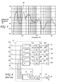
- FIG. 2 is a prior art signal processing flow for a home theater speaker suite.
- FIG. 3 shows typical magnitude responses for a speaker of the speaker suite.
- FIG. 4A is a frequency response for a subwoofer.
- FIG. 4B is a frequency response for a speaker.
- FIG. 5 is a combined subwoofer and speaker magnitude response having a spectral notch.
- FIG. 6 is a signal processing flow for a prior art signal processor including equalization filters.
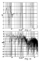
- FIG. 7 is a combined speaker and subwoofer magnitude response for a cross-over frequency of 30 Hz.
- FIG. 8 is a third octave smoothed magnitude response corresponding to FIG. 7 .
- FIG. 9 shown the effect of phase incoherence.
- FIG. 10 shows the net reduction in magnitude response due to phase incoherence.
- FIG. 11 is a family of unwrapped phases for all-pass filters.
- FIG. 12 shows group delays for the all-pass filters.
- FIG. 13 is an original phase difference function.
- FIG. 14 is a phase difference function after all-pass filtering.
- FIG. 15 is the phase correction introduced by the all-pass filtering.
- FIG. 16 is the net magnitude response in the cross-over region resulting from the all-pass filtering
- FIG. 17 is a third octave smoother representation of FIG. 16 .
- FIG. 18 is a plot of the third octave smoother representation superimposed on the third octave smoother before all-pass filtering.
- FIG. 19 is a signal processor flow according to the present invention including all-pass filters.
- FIG. 20 is a method according to the present invention.
- FIG. 21 is a method for computing all-pass filter coefficients according to the present invention.
- FIG. 1 A typical home theater 10 is shown in FIG. 1 .
- the home theater 10 comprises a media player (for example, a DVD player) 11 , a signal processor 12 , a monitor (or television) 14 , a center speaker 16 , left and right front speakers 18 a and 18 b respectively, left and right rear (or surround) speakers 20 a and 20 b respectively (the speakers 16 , 18 a , 18 b , 20 a , and 20 b subsequently referred to as satellite speakers), a subwoofer speaker 22 , and a listening position 24 .
- the media player 11 provides video and audio signals to the signal processor 12 .
- the signal processor 12 in often an audio video receiver including a multiplicity of functions, for example, a tuner, a pre-amplifier, a power amplifier, and signal processing circuits (for example, a family of graphic equalizers) to condition (or color) the speaker signals to match a listener's preferences and/or room acoustics.
- a multiplicity of functions for example, a tuner, a pre-amplifier, a power amplifier, and signal processing circuits (for example, a family of graphic equalizers) to condition (or color) the speaker signals to match a listener's preferences and/or room acoustics.
- Signal processors 12 used in home theater systems 10 which home theater systems 10 includes a subwoofer 22 , also generally include cross-over filters 30 a - 30 e and 32 (also called bass-management filters) as shown in FIG. 2 .
- the subwoofer 22 is designed to produce low frequency sound waves, and may cause distortion if it receives high frequency electrical signals.
- the center, front, and rear speakers 16 , 18 a , 18 b , 20 a , and 20 b are designed to produce moderate and high frequency sound waves, and may cause distortion if they receive low frequency electrical signals.
- the unfiltered (or full-range) signals 26 a - 26 e provided to the speakers 16 , 18 a , 18 b , 20 a , and 20 b are processed through high pass filters 30 a - 30 e to generate filtered (or bass-managed) speaker signals 38 a - 38 e .
- the same unfiltered signals 26 a - 26 e are processed by a lowpass filter 32 and summed with a subwoofer signal 28 in a summer 34 to generate a filtered (or bass-managed) subwoofer signal 40 provided to the subwoofer 22 .
- FIG. 2 An example of a system including a prior art signal processor 12 as described in FIG. 2 is a THX® certified speaker system.
- the frequency responses of THX® bass-management filters for subwoofer and satellite speakers of such THX® certified speaker system are shown in FIG. 3 .
- Such THX® speaker system certified signal processors are designed with a cross-over frequency (i.e., the 3 dB point) of 80 Hz and include a bass management filter 32 preferably comprising a fourth order low-pass Butterworth filter (or a dual stage filter, each stage being a second order low-pass Butterworth filter) having a roll off rate of approximately 24 dB/octave above 80 Hz (with low pass response 44 ), and high pass bass management filters 30 a - 30 e comprising a second order Butterworth filter having a roll-off rate of approximately 12 DB per octave below 80 Hz (with high pass response 42 ).
- a bass management filter 32 preferably comprising a fourth order low-pass Butterworth filter (or a dual stage filter, each stage being a second order low-pass Butterworth filter) having a roll off rate of approximately 24 dB/octave above 80 Hz (with low pass response 44 )
- high pass bass management filters 30 a - 30 e
- THX® speaker system certified signal processors conform to the THX® speaker system standard, many speaker systems do not include THX® speaker system certified signal processors.
- Such non-THX® systems (and even THX® speaker systems) often benefit from selection of a cross-over frequency dependent upon the signal processor 12 , satellite speakers 16 , 18 a , 18 b , 20 a , 20 b , subwoofer speaker 22 , listener position, and listener preference.
- the 24 dB/octave and 12 dB/octave filter slopes may still be utilized to provide adequately good performance.
- individual subwoofer 22 and non-subwoofer speaker in this example the center channel speaker 16 in FIG. 2 ) full-range (i.e., non bass-managed or without high pass or low pass filtering) frequency responses (one third octave smoothed), as measured in a room with reverberation time T 60 of approximately 0.75 seconds, are shown in FIGS. 4A and 4B respectively.
- the center channel speaker 16 has a center channel frequency response 48 extending below 100 Hz (down to about 40 Hz)
- the subwoofer 22 has a subwoofer frequency response 46 extending up to about 200 Hz.
- the satellite speakers 16 , 18 a , 18 b , 20 a , 20 b , and subwoofer speaker 22 as shown in FIG. 1 generally reside at different positions around a room, for example, the subwoofer 22 may be at one side of the room, while the center channel speaker 16 is generally position near the monitor 14 . Due to such non-coincident positions of the speakers, the sound waves near the cross-over frequency may add incoherently (i.e., at or near 180 degrees out of phase), thereby creating a spectral notch 50 and/or other substantial amplitude variations in the cross-over region shown in FIG. 5 . Such spectral notch 50 and/or amplitude variations may further vary by listening position 24 , and more specifically by acoustic path differences from the individual satellite speakers and subwoofer speaker to the listening position 24 .
- the spectral notch 50 and/or amplitude variations in the cross-over region may contribute to loss of acoustical efficiency because some of the sound around the cross-over frequency may be undesirably attenuated or amplified.
- the spectral notch 50 may result in a significant loss of sound reproduction to as low as 40 Hz (about the lowest frequency which the center channel speaker 16 is capable of producing).
- Such spectral notches have been verified using real world measurements, where the subwoofer speaker 22 and satellite speakers 16 , 18 a , 18 b , 20 a , and 20 b were excited with a broadband stimuli (for example, log-chirp signal) and the net response was de-convolved from the measured signal.
- a broadband stimuli for example, log-chirp signal
- known signal processors 12 may include equalization filters 52 a - 52 e , and 54 , as shown in FIG. 6 .
- the equalization filters 52 a - 52 e , and 54 provides some ability to tune the sound reproduction for a particular room environment and/or listener preference, the equalization filters 52 a - 52 e , and 54 do not generally remove the spectral notch 50 , nor do they minimize the variations in the response in the cross-over region.
- the equalization filters 52 a - 52 e , and 54 are minimum phase and as such often do little to influence the frequency response around the cross-over.
- the present invention provides a system and method for minimizing the spectral notching 50 and/or response variations in the cross-over region. While the embodiment of the present invention described herein does not describe the application of the present invention to systems including equalization filters for each channel, the method of the present invention is easily extended to such systems.
- the home theater 10 generally resides in a room comprising an acoustic enclosure which can be modeled as a linear system whose behavior at a particular listening position is characterized by a time domain impulse function, h(n); n ⁇ 0, 1, 2, . . . ⁇ .
- the impulse response h(n) is generally called the room impulse response which has an associated frequency response, H(e j ⁇ ) which is a function of frequency (for example, between 20 Hz and 20,000 Hz).
- H(e j ⁇ ) is generally referred to the Room Transfer Function (RTF).
- the time domain response h(n) and the frequency domain response RTF are linearly related through the Fourier transform, that is, given one we can find the other via the Fourier relations, wherein the Fourier transform of the time domain response yields the RTF.
- the RTF provides a complete description of the changes the acoustic signal undergoes when it travels from a source to a receiver (microphone/listener).
- the RTF may be measured by transmitting an appropriate signal, for example, a logarithmic chirp signal, from a speaker, and deconvolving a response at a listener position.
- the impulse responses h(n) and H(e j ⁇ ) yield a complete description of the changes the acoustic signal undergoes when it travels from a source (e.g. speaker) to a receiver (e.g., microphone/listener).
- the signal at a listening position 24 consists of direct path components, discrete reflections which arrive a few milliseconds after the direct path components, as well as reverberant field components.
- phase interaction between speakers may be understood through the complex addition of frequency responses (i.e., time domain edition) from linear system theory. Specifically, the addition is most interesting when observed through the magnitude response of the resulting addition between subwoofer and satellite speakers.
- the resulting squared magnitude response is:
- phase response of the subwoofer 22 and the satellite speaker 16 , 18 a , 18 b , 20 a , or 20 b are given by ⁇ sub ( ⁇ ) and ⁇ sat ( ⁇ ) respectively.
- the resulting magnitude response is actually the difference between the magnitude responses of the subwoofer and satellite speaker thereby, possibly introducing a spectral notch 50 around the cross-over frequency.
- FIG. 7 shows an exemplary combined subwoofer and center channel speaker response in a room with reverberation time of about 0.75 seconds.
- a large spectral notch is observed around the cross-over frequency, and one of the reasons for the introduction of this cross-over notch is the additive term ⁇ (e j ⁇ ) which adds incoherently to the magnitude response sum.
- FIG. 8 is a third octave smoothed magnitude response corresponding to FIG. 7 , or as FIG.
- FIG. 9 shows the effect of the ⁇ (e j ⁇ ) term clearly exhibiting an inhibitory effect around the cross-over region due to the phase interaction between the subwoofer and the satellite speaker response at the listener position 24 (see FIG. 1 ).
- the cosine of the phase difference (viz., cos( ⁇ sub ( ⁇ ) ⁇ sat ( ⁇ ))), that causes the reduction in net magnitude response, is shown in FIG. 10 .
- ⁇ (e j ⁇ ) term provides improved net magnitude response in the cross-over region.
- All-pass filters 60 a - 60 e may be included in the signal processor 12 .
- the all-pass filters 60 a - 60 e have unit magnitude response across the frequency spectrum, while introducing frequency dependent group delays (e.g., frequency shifts).
- the all-pass filters 60 a - 60 e are preferably cascaded with the high pass filters 30 a - 30 e and are preferably M-cascade all-pass filters A M (e j ) where each section in the cascade comprises a second order all-pass filter.
- a family of all-pass filter unwrapped phases as a function of frequency is plotted in FIG. 11 .
- a second order all-pass filter, A(z) may be expressed as:
- the first order all-pass filter in the satellite channel (e.g., center channel).
- the all-pass filter were to be placed in the subwoofer channel, the net response between the subwoofer and the remaining channels (e.g., left front, right front, left rear, and/or right rear,) could be affected and undesirable manner.
- the all-pass filter is cascaded with the satellite speaker signal processing (e.g., the bass-management filter) to reduce or remove the effects of phase between each satellite speaker and the subwoofer at a particular listening position.
- the method of the present invention may be adapted to include information describing the net response at multiple listening positions so as to optimize the ⁇ term in order to minimize the effects of phase interaction over multiple positions.
- the attenuation of the spectral notch is achieved by adaptively minimizing a phase term: ⁇ sub ( ⁇ ) ⁇ speaker ( ⁇ ) ⁇ A M ( ⁇ ) where:
- ⁇ sub ( ⁇ ) the phase spectrum for the subwoofer 22 ;
- ⁇ speaker ( ⁇ ) the phase spectrum for the satellite speakers 16 , 18 a , 18 b , 20 a , or 20 b ;
- ⁇ A M ( ⁇ ) the phase spectrum of the all-pass filter.
- 2 of a subwoofer and satellite speaker suite having an M-cascade all-pass filter A M (e j ⁇ ) in the satellite speaker channel may be expressed as:
- ⁇ H ⁇ ( e j ⁇ ) ⁇ 2 ⁇ ⁇ H ⁇ sub ⁇ ( ⁇ ) ⁇ 2 + ⁇ H ⁇ sat ⁇ ( ⁇ ) ⁇ 2 + ⁇ 2 ⁇ ⁇ H ⁇ sub ⁇ ( ⁇ ) ⁇ ⁇ ⁇ H ⁇ sat ⁇ ( ⁇ ) ⁇ ⁇ cos ⁇ ⁇ ( ⁇ sub ⁇ ( ⁇ ) - ⁇ sat ⁇ ( ⁇ ) - ⁇ A M ⁇ ( ⁇ ) )
- the M cascade all-pass filter A M may be expressed as:
- W( ⁇ i ) is a frequency dependent weighting function.
- the recursive update equations are:
- ⁇ r and ⁇ ⁇ are adaptation rate control parameters chosen to guarantee stable convergence and are typically between zero and one.
- the magnitude of the pole radius r i (n) is preferably kept less than one.
- a preferable method for keeping the magnitude of the pole radius r i (n) less than one is to randomize r i (n) between zero and one whenever r i (n) is greater than or equal to one.
- the original phase difference function ( ⁇ sub ( ⁇ ) ⁇ sat( ⁇ )) 2 is plotted in FIG. 13 and the cosine term cos( ⁇ sub ( ⁇ ) ⁇ sat ( ⁇ )) which shows incoherent shown in FIG. 10 as can be seen, by minimizing the phase difference (using all-pass filter cascaded in the satellite channel) around the cross-over region will minimize the spectral notch.
- the resulting all-pass filter and phase difference function ( ⁇ sub ( ⁇ ) ⁇ sat ( ⁇ ) ⁇ A M ( ⁇ )) 2 resulting from the adaptation of r i (n) and ⁇ i (n) is shown in FIG. 14 , thereby demonstrating the minimization of the phase difference around the cross-over.
- FIG. 15 The resulting all-pass filtering term, ⁇ F ( ⁇ ), and is shown in FIG. 15 . Comparing FIGS. 9 and 15 , it may be seen that the inhibition turns to an excitation to the net magnitude response around the cross-over region.
- FIG. 16 shows the resulting combined magnitude response with the cascade all-pass filter in the satellite channel
- FIG. 17 shows the third octave smoothed version of FIG. 16 .
- a superimposed plot, comprising FIG. 17 and the original combined response of FIG. 8 is depicted in FIG. 18 and an improvement of about 70 be around the cross-over may be seen.
- All-pass filters 60 a - 60 e are cascaded with high pass (or bass-management) filters 30 a - 30 e.
- the method comprises defining at least one second order all-pass filter at step 96 , recursively computing all-pass filter coefficients at step 98 , and cascading the at least one all-pass filter with at least one bass-management filter at step 100 .
- the at least one all-pass filter is preferably a plurality of all-pass filters and are preferably cascaded with high-pass filters processing signals for satellite speakers 16 , 18 a , 18 b , 20 a , and 20 b shown in FIG. 1 .
- the recursively computing all-pass filter weights step 98 preferably comprises a computing methods described in FIG. 21 .
- the computing method comprises the steps of selecting initial values for pole angles ⁇ i and magnitudes r i at step 102 , computing gradients ⁇ ri and ⁇ ⁇ i for pole angle and magnitude at step 104 , multiplying the angle and magnitude gradients ⁇ ri and ⁇ ⁇ i times an error function J(n) and times adaptation rate control parameters ⁇ r and ⁇ ⁇ to obtain increments at step 106 , adding the increments to the pole angles and magnitudes to recursively compute new pole angles and magnitudes at step 108 , randomizing the pole magnitude if the pole magnitude is ⁇ 1 at step 110 , and testing to determine if the pole angle and magnitudes have converged at step 112 . If the pole angle and magnitudes have converged, the computing method is done, otherwise, the steps 104 , 106 , 108 , 110 , and 112 are repeated.
- the methods of the present invention may further include a method for selecting an optimal cross-over frequency including the steps of measuring the full-range (i.e., non bass-managed) subwoofer and satellite speaker response in at least one position in a room, selecting a cross-over region, selecting a set of candidate cross-over frequencies and corresponding bass-management filters for the subwoofer and the satellite speaker, applying the corresponding bass-management filters to the subwoofer and satellite speaker full-range response, level matching the bass managed subwoofer and satellite speaker response, performing addition of the subwoofer and satellite speaker response to obtain the net bass-managed subwoofer and satellite speaker response, computing an objective function using the net response for each of the candidate cross-over frequencies, and selecting the candidate cross-over frequency resulting in the lowest objective function.
- a method for selecting an optimal cross-over frequency including the steps of measuring the full-range (i.e., non bass-managed) subwoofer and satellite speaker response in at least one position in a room, selecting a cross-over region, selecting a set of candidate cross
Abstract
Description
where {tilde over (H)}subejω and {tilde over (H)}satejω are bass-managed subwoofer and satellite room responses measured at a listening position l in the room, and where At(ejω) is the complex conjugate of A(ejω). The phase response of the
{tilde over (H)} sub(e jω)=BM sub(e jω)H sub(e jω)
and,
{tilde over (H)} sat(e jω)=BM sat(e jω)H sat(e jω)
where BMsub(ejω) and BMsat(ejω) are the THX® bass-management Infinite Impulse Response (IIR) filters, and Hsub(ejω) and Hsat(ejω) are the full-range subwoofer and satellite speaker responses respectively.
Λ(e jω)=2|H sub(e jω)∥H sat(e jω)|cos(φsub(ω)−φsat(ω))
This term influences the combined magnitude response, generally, in a detrimental manner, when it adds incoherently to the magnitude response sum of the subwoofer and satellite speakers. Specifically, when:
φsub(ω)=φsat(ω)+kπ(k=1, 3, 5, . . . )
where zi=riejθ
φsub(ω)−φspeaker(ω)−φA
where:
where the M cascade all-pass filter AM may be expressed as:
and the additive term ΛF(ejω) may be expressed as:
ΛF(e jω)=2|{tilde over (H)} sub(ω)|·|{tilde over (H)} sat(ω)|·cos(φsub(ω)−φsat(ω)−φA
Thus, to minimize the negative affect of the Λ term, (or effectively cause Λ to add coherently to |{tilde over (H)}sub(ω)|2+|{tilde over (H)}sat(ω)|2, in the example above, a preferred objective function, J(n) may be defined as:
Where W(ωi) is a frequency dependent weighting function. The terms ri and θi, (i=1, 2, 3, . . . M) may be determined using an adaptive recursive formula by minimizing the objective function J(n) with respect to ri and θi. The recursive update equations are:
where μr and μθ are adaptation rate control parameters chosen to guarantee stable convergence and are typically between zero and one. Finally, the gradients of the objective function J(n) with respect to the parameters of the all-pass function is are:
Claims (10)
Priority Applications (2)
| Application Number | Priority Date | Filing Date | Title |
|---|---|---|---|
| US11/222,000 US7720237B2 (en) | 2004-09-07 | 2005-09-07 | Phase equalization for multi-channel loudspeaker-room responses |
| US12/753,051 US8218789B2 (en) | 2004-09-07 | 2010-04-01 | Phase equalization for multi-channel loudspeaker-room responses |
Applications Claiming Priority (2)
| Application Number | Priority Date | Filing Date | Title |
|---|---|---|---|
| US60760204P | 2004-09-07 | 2004-09-07 | |
| US11/222,000 US7720237B2 (en) | 2004-09-07 | 2005-09-07 | Phase equalization for multi-channel loudspeaker-room responses |
Related Child Applications (1)
| Application Number | Title | Priority Date | Filing Date |
|---|---|---|---|
| US12/753,051 Continuation US8218789B2 (en) | 2004-09-07 | 2010-04-01 | Phase equalization for multi-channel loudspeaker-room responses |
Publications (2)
| Publication Number | Publication Date |
|---|---|
| US20060056646A1 US20060056646A1 (en) | 2006-03-16 |
| US7720237B2 true US7720237B2 (en) | 2010-05-18 |
Family
ID=36033969
Family Applications (2)
| Application Number | Title | Priority Date | Filing Date |
|---|---|---|---|
| US11/222,000 Active 2029-03-18 US7720237B2 (en) | 2004-09-07 | 2005-09-07 | Phase equalization for multi-channel loudspeaker-room responses |
| US12/753,051 Active 2026-02-28 US8218789B2 (en) | 2004-09-07 | 2010-04-01 | Phase equalization for multi-channel loudspeaker-room responses |
Family Applications After (1)
| Application Number | Title | Priority Date | Filing Date |
|---|---|---|---|
| US12/753,051 Active 2026-02-28 US8218789B2 (en) | 2004-09-07 | 2010-04-01 | Phase equalization for multi-channel loudspeaker-room responses |
Country Status (1)
| Country | Link |
|---|---|
| US (2) | US7720237B2 (en) |
Cited By (33)
| Publication number | Priority date | Publication date | Assignee | Title |
|---|---|---|---|---|
| US20070165878A1 (en) * | 2004-01-05 | 2007-07-19 | Yamaha Corporation | Loudspeaker array audio signal supply apparartus |
| US20070217621A1 (en) * | 2004-08-26 | 2007-09-20 | Yamaha Corporation | Audio reproduction apparatus |
| US20080101631A1 (en) * | 2006-11-01 | 2008-05-01 | Samsung Electronics Co., Ltd. | Front surround sound reproduction system using beam forming speaker array and surround sound reproduction method thereof |
| US20080159545A1 (en) * | 2004-01-07 | 2008-07-03 | Yamaha Corporation | Speaker System |
| US20090060237A1 (en) * | 2005-02-25 | 2009-03-05 | Yamaha Corporation | Array speaker system |
| US20100070226A1 (en) * | 2008-09-12 | 2010-03-18 | Jack Harris Arnold | Analysis of Chirp Frequency Response Using Arbitrary Resampling Filters |
| US20100189282A1 (en) * | 2004-09-07 | 2010-07-29 | Audyssey Laboratories, Inc. | Phase equalization for multi-channel loudspeaker-room responses |
| US20100310092A1 (en) * | 2004-09-07 | 2010-12-09 | Audyssey Laboratories, Inc. | Cross-over frequency selection and optimization of response around cross-over |
| US8705764B2 (en) | 2010-10-28 | 2014-04-22 | Audyssey Laboratories, Inc. | Audio content enhancement using bandwidth extension techniques |
| US9781510B2 (en) | 2012-03-22 | 2017-10-03 | Dirac Research Ab | Audio precompensation controller design using a variable set of support loudspeakers |
| US10284983B2 (en) | 2015-04-24 | 2019-05-07 | Sonos, Inc. | Playback device calibration user interfaces |
| US10299061B1 (en) | 2018-08-28 | 2019-05-21 | Sonos, Inc. | Playback device calibration |
| US10299054B2 (en) | 2016-04-12 | 2019-05-21 | Sonos, Inc. | Calibration of audio playback devices |
| US10299055B2 (en) | 2014-03-17 | 2019-05-21 | Sonos, Inc. | Restoration of playback device configuration |
| US10334386B2 (en) | 2011-12-29 | 2019-06-25 | Sonos, Inc. | Playback based on wireless signal |
| US10405117B2 (en) | 2016-01-18 | 2019-09-03 | Sonos, Inc. | Calibration using multiple recording devices |
| US10402154B2 (en) | 2016-04-01 | 2019-09-03 | Sonos, Inc. | Playback device calibration based on representative spectral characteristics |
| US10405116B2 (en) | 2016-04-01 | 2019-09-03 | Sonos, Inc. | Updating playback device configuration information based on calibration data |
| US10412517B2 (en) * | 2014-03-17 | 2019-09-10 | Sonos, Inc. | Calibration of playback device to target curve |
| US10419864B2 (en) | 2015-09-17 | 2019-09-17 | Sonos, Inc. | Validation of audio calibration using multi-dimensional motion check |
| US10462592B2 (en) | 2015-07-28 | 2019-10-29 | Sonos, Inc. | Calibration error conditions |
| US10459684B2 (en) | 2016-08-05 | 2019-10-29 | Sonos, Inc. | Calibration of a playback device based on an estimated frequency response |
| US10585639B2 (en) | 2015-09-17 | 2020-03-10 | Sonos, Inc. | Facilitating calibration of an audio playback device |
| US10599386B2 (en) | 2014-09-09 | 2020-03-24 | Sonos, Inc. | Audio processing algorithms |
| US10664224B2 (en) | 2015-04-24 | 2020-05-26 | Sonos, Inc. | Speaker calibration user interface |
| US10674293B2 (en) | 2012-06-28 | 2020-06-02 | Sonos, Inc. | Concurrent multi-driver calibration |
| US10701501B2 (en) | 2014-09-09 | 2020-06-30 | Sonos, Inc. | Playback device calibration |
| US10734965B1 (en) | 2019-08-12 | 2020-08-04 | Sonos, Inc. | Audio calibration of a portable playback device |
| US10735879B2 (en) | 2016-01-25 | 2020-08-04 | Sonos, Inc. | Calibration based on grouping |
| US10750303B2 (en) | 2016-07-15 | 2020-08-18 | Sonos, Inc. | Spatial audio correction |
| US10853022B2 (en) | 2016-07-22 | 2020-12-01 | Sonos, Inc. | Calibration interface |
| US11106423B2 (en) | 2016-01-25 | 2021-08-31 | Sonos, Inc. | Evaluating calibration of a playback device |
| US11206484B2 (en) | 2018-08-28 | 2021-12-21 | Sonos, Inc. | Passive speaker authentication |
Families Citing this family (30)
| Publication number | Priority date | Publication date | Assignee | Title |
|---|---|---|---|---|
| JP4081768B2 (en) * | 2004-03-03 | 2008-04-30 | ソニー株式会社 | Plural sound reproducing device, plural sound reproducing method, and plural sound reproducing system |
| US10158337B2 (en) | 2004-08-10 | 2018-12-18 | Bongiovi Acoustics Llc | System and method for digital signal processing |
| US11431312B2 (en) | 2004-08-10 | 2022-08-30 | Bongiovi Acoustics Llc | System and method for digital signal processing |
| US10848118B2 (en) | 2004-08-10 | 2020-11-24 | Bongiovi Acoustics Llc | System and method for digital signal processing |
| US8284955B2 (en) | 2006-02-07 | 2012-10-09 | Bongiovi Acoustics Llc | System and method for digital signal processing |
| US8355510B2 (en) * | 2004-12-30 | 2013-01-15 | Harman International Industries, Incorporated | Reduced latency low frequency equalization system |
| US9008331B2 (en) * | 2004-12-30 | 2015-04-14 | Harman International Industries, Incorporated | Equalization system to improve the quality of bass sounds within a listening area |
| LV13342B (en) * | 2005-05-18 | 2005-10-20 | Real Sound Lab Sia | Method and device for correction of acoustic parameters of electro-acoustic transducers |
| US9314222B2 (en) * | 2005-07-07 | 2016-04-19 | Stereotaxis, Inc. | Operation of a remote medical navigation system using ultrasound image |
| US10069471B2 (en) | 2006-02-07 | 2018-09-04 | Bongiovi Acoustics Llc | System and method for digital signal processing |
| US11202161B2 (en) | 2006-02-07 | 2021-12-14 | Bongiovi Acoustics Llc | System, method, and apparatus for generating and digitally processing a head related audio transfer function |
| US10848867B2 (en) | 2006-02-07 | 2020-11-24 | Bongiovi Acoustics Llc | System and method for digital signal processing |
| US10701505B2 (en) | 2006-02-07 | 2020-06-30 | Bongiovi Acoustics Llc. | System, method, and apparatus for generating and digitally processing a head related audio transfer function |
| US8229143B2 (en) * | 2007-05-07 | 2012-07-24 | Sunil Bharitkar | Stereo expansion with binaural modeling |
| KR100930835B1 (en) * | 2008-01-29 | 2009-12-10 | 한국과학기술원 | Sound playback device |
| TWI465122B (en) | 2009-01-30 | 2014-12-11 | Dolby Lab Licensing Corp | Method for determining inverse filter from critically banded impulse response data |
| JP5347902B2 (en) * | 2009-10-22 | 2013-11-20 | ヤマハ株式会社 | Sound processor |
| EP2357846A1 (en) * | 2009-12-22 | 2011-08-17 | Harman Becker Automotive Systems GmbH | Group-delay based bass management |
| US9059786B2 (en) * | 2011-07-07 | 2015-06-16 | Vecima Networks Inc. | Ingress suppression for communication systems |
| US9883318B2 (en) | 2013-06-12 | 2018-01-30 | Bongiovi Acoustics Llc | System and method for stereo field enhancement in two-channel audio systems |
| US9264004B2 (en) * | 2013-06-12 | 2016-02-16 | Bongiovi Acoustics Llc | System and method for narrow bandwidth digital signal processing |
| US9906858B2 (en) | 2013-10-22 | 2018-02-27 | Bongiovi Acoustics Llc | System and method for digital signal processing |
| US9402145B2 (en) | 2014-01-24 | 2016-07-26 | Sony Corporation | Wireless speaker system with distributed low (bass) frequency |
| US10820883B2 (en) | 2014-04-16 | 2020-11-03 | Bongiovi Acoustics Llc | Noise reduction assembly for auscultation of a body |
| US10639000B2 (en) | 2014-04-16 | 2020-05-05 | Bongiovi Acoustics Llc | Device for wide-band auscultation |
| JP2018537910A (en) | 2015-11-16 | 2018-12-20 | ボンジョビ アコースティックス リミテッド ライアビリティー カンパニー | Surface acoustic transducer |
| US9621994B1 (en) | 2015-11-16 | 2017-04-11 | Bongiovi Acoustics Llc | Surface acoustic transducer |
| WO2018186779A1 (en) | 2017-04-07 | 2018-10-11 | Dirac Research Ab | A novel parametric equalization for audio applications |
| CN112236812A (en) | 2018-04-11 | 2021-01-15 | 邦吉欧维声学有限公司 | Audio-enhanced hearing protection system |
| WO2020028833A1 (en) | 2018-08-02 | 2020-02-06 | Bongiovi Acoustics Llc | System, method, and apparatus for generating and digitally processing a head related audio transfer function |
Citations (29)
| Publication number | Priority date | Publication date | Assignee | Title |
|---|---|---|---|---|
| US4109107A (en) | 1977-07-05 | 1978-08-22 | Iowa State University Research Foundation, Inc. | Method and apparatus for frequency compensation of electro-acoustical transducer and its environment |
| US4694498A (en) | 1984-10-31 | 1987-09-15 | Pioneer Electronic Corporation | Automatic sound field correcting system |
| US4771466A (en) * | 1983-10-07 | 1988-09-13 | Modafferi Acoustical Systems, Ltd. | Multidriver loudspeaker apparatus with improved crossover filter circuits |
| US4888809A (en) | 1987-09-16 | 1989-12-19 | U.S. Philips Corporation | Method of and arrangement for adjusting the transfer characteristic to two listening position in a space |
| US5185801A (en) | 1989-12-28 | 1993-02-09 | Meyer Sound Laboratories Incorporated | Correction circuit and method for improving the transient behavior of a two-way loudspeaker system |
| US5572443A (en) | 1993-05-11 | 1996-11-05 | Yamaha Corporation | Acoustic characteristic correction device |
| US5771294A (en) | 1993-09-24 | 1998-06-23 | Yamaha Corporation | Acoustic image localization apparatus for distributing tone color groups throughout sound field |
| US5815580A (en) | 1990-12-11 | 1998-09-29 | Craven; Peter G. | Compensating filters |
| US5930374A (en) * | 1996-10-17 | 1999-07-27 | Aphex Systems, Ltd. | Phase coherent crossover |
| US6064770A (en) | 1995-06-27 | 2000-05-16 | National Research Council | Method and apparatus for detection of events or novelties over a change of state |
| US6072877A (en) | 1994-09-09 | 2000-06-06 | Aureal Semiconductor, Inc. | Three-dimensional virtual audio display employing reduced complexity imaging filters |
| US6118875A (en) | 1994-02-25 | 2000-09-12 | Moeller; Henrik | Binaural synthesis, head-related transfer functions, and uses thereof |
| US20010038702A1 (en) | 2000-04-21 | 2001-11-08 | Lavoie Bruce S. | Auto-Calibrating Surround System |
| US6519344B1 (en) | 1998-09-30 | 2003-02-11 | Pioneer Corporation | Audio system |
| US20030112981A1 (en) | 2001-12-17 | 2003-06-19 | Siemens Vdo Automotive, Inc. | Active noise control with on-line-filtered C modeling |
| US20030200236A1 (en) | 2002-04-19 | 2003-10-23 | Yan Hong | Curve tracing system |
| US6650756B1 (en) | 1997-05-21 | 2003-11-18 | Alpine Electronics, Inc. | Method and apparatus for characterizing audio transmitting system, and method and apparatus for setting characteristics of audio filter |
| US6650776B2 (en) | 1998-06-30 | 2003-11-18 | Sony Corporation | Two-dimensional code recognition processing method, two-dimensional code recognition processing apparatus, and storage medium |
| US20030235318A1 (en) | 2002-06-21 | 2003-12-25 | Sunil Bharitkar | System and method for automatic room acoustic correction in multi-channel audio environments |
| US6721428B1 (en) | 1998-11-13 | 2004-04-13 | Texas Instruments Incorporated | Automatic loudspeaker equalizer |
| US6760451B1 (en) * | 1993-08-03 | 2004-07-06 | Peter Graham Craven | Compensating filters |
| US6792114B1 (en) | 1998-10-06 | 2004-09-14 | Gn Resound A/S | Integrated hearing aid performance measurement and initialization system |
| US6854005B2 (en) | 1999-09-03 | 2005-02-08 | Techstream Pty Ltd. | Crossover filter system and method |
| US20050031135A1 (en) | 2003-08-04 | 2005-02-10 | Devantier Allan O. | Statistical analysis of potential audio system configurations |
| US20050069153A1 (en) | 2003-09-26 | 2005-03-31 | Hall David S. | Adjustable speaker systems and methods |
| US20050157891A1 (en) | 2002-06-12 | 2005-07-21 | Johansen Lars G. | Method of digital equalisation of a sound from loudspeakers in rooms and use of the method |
| US20050220312A1 (en) * | 1998-07-31 | 2005-10-06 | Joji Kasai | Audio signal processing circuit |
| US6956955B1 (en) | 2001-08-06 | 2005-10-18 | The United States Of America As Represented By The Secretary Of The Air Force | Speech-based auditory distance display |
| US6980665B2 (en) | 2001-08-08 | 2005-12-27 | Gn Resound A/S | Spectral enhancement using digital frequency warping |
Family Cites Families (14)
| Publication number | Priority date | Publication date | Assignee | Title |
|---|---|---|---|---|
| US3067297A (en) | 1960-02-26 | 1962-12-04 | Philco Corp | Apparatus for determining the polarities of stereophonic channel connections at anyselected point |
| US4514596A (en) | 1980-07-17 | 1985-04-30 | Plessey Overseas Limited | Telephone handsets |
| US4698842A (en) | 1985-07-11 | 1987-10-06 | Electronic Engineering And Manufacturing, Inc. | Audio processing system for restoring bass frequencies |
| US4908868A (en) | 1989-02-21 | 1990-03-13 | Mctaggart James E | Phase polarity test instrument and method |
| US5319714A (en) | 1992-09-23 | 1994-06-07 | Mctaggart James E | Audio phase polarity test system |
| US5727074A (en) * | 1996-03-25 | 1998-03-10 | Harold A. Hildebrand | Method and apparatus for digital filtering of audio signals |
| US5930373A (en) | 1997-04-04 | 1999-07-27 | K.S. Waves Ltd. | Method and system for enhancing quality of sound signal |
| EP1044583B2 (en) | 1998-09-08 | 2007-09-05 | Koninklijke Philips Electronics N.V. | Means for bass enhancement in an audio system |
| JP3286603B2 (en) | 1998-09-22 | 2002-05-27 | ヤマハ株式会社 | Speaker polarity discrimination circuit, audio circuit with speaker polarity discrimination function, audio circuit with speaker polarity discrimination and polarity switching function |
| CN1274184C (en) | 2001-09-21 | 2006-09-06 | 西门子公司 | Method and apparatus for controlling bass reproduction of audio frequency signal in electroacoustic transducer |
| US7567675B2 (en) | 2002-06-21 | 2009-07-28 | Audyssey Laboratories, Inc. | System and method for automatic multiple listener room acoustic correction with low filter orders |
| AU2003281100A1 (en) * | 2002-07-10 | 2004-02-02 | Koninklijke Philips Electronics N.V. | A stereo signal processing apparatus |
| US7720237B2 (en) | 2004-09-07 | 2010-05-18 | Audyssey Laboratories, Inc. | Phase equalization for multi-channel loudspeaker-room responses |
| US7826626B2 (en) | 2004-09-07 | 2010-11-02 | Audyssey Laboratories, Inc. | Cross-over frequency selection and optimization of response around cross-over |
-
2005
- 2005-09-07 US US11/222,000 patent/US7720237B2/en active Active
-
2010
- 2010-04-01 US US12/753,051 patent/US8218789B2/en active Active
Patent Citations (31)
| Publication number | Priority date | Publication date | Assignee | Title |
|---|---|---|---|---|
| US4109107A (en) | 1977-07-05 | 1978-08-22 | Iowa State University Research Foundation, Inc. | Method and apparatus for frequency compensation of electro-acoustical transducer and its environment |
| US4771466A (en) * | 1983-10-07 | 1988-09-13 | Modafferi Acoustical Systems, Ltd. | Multidriver loudspeaker apparatus with improved crossover filter circuits |
| US4694498A (en) | 1984-10-31 | 1987-09-15 | Pioneer Electronic Corporation | Automatic sound field correcting system |
| US4888809A (en) | 1987-09-16 | 1989-12-19 | U.S. Philips Corporation | Method of and arrangement for adjusting the transfer characteristic to two listening position in a space |
| US5185801A (en) | 1989-12-28 | 1993-02-09 | Meyer Sound Laboratories Incorporated | Correction circuit and method for improving the transient behavior of a two-way loudspeaker system |
| US5377274A (en) * | 1989-12-28 | 1994-12-27 | Meyer Sound Laboratories Incorporated | Correction circuit and method for improving the transient behavior of a two-way loudspeaker system |
| US5815580A (en) | 1990-12-11 | 1998-09-29 | Craven; Peter G. | Compensating filters |
| US5572443A (en) | 1993-05-11 | 1996-11-05 | Yamaha Corporation | Acoustic characteristic correction device |
| US6760451B1 (en) * | 1993-08-03 | 2004-07-06 | Peter Graham Craven | Compensating filters |
| US5771294A (en) | 1993-09-24 | 1998-06-23 | Yamaha Corporation | Acoustic image localization apparatus for distributing tone color groups throughout sound field |
| US6118875A (en) | 1994-02-25 | 2000-09-12 | Moeller; Henrik | Binaural synthesis, head-related transfer functions, and uses thereof |
| US6072877A (en) | 1994-09-09 | 2000-06-06 | Aureal Semiconductor, Inc. | Three-dimensional virtual audio display employing reduced complexity imaging filters |
| US6064770A (en) | 1995-06-27 | 2000-05-16 | National Research Council | Method and apparatus for detection of events or novelties over a change of state |
| US5930374A (en) * | 1996-10-17 | 1999-07-27 | Aphex Systems, Ltd. | Phase coherent crossover |
| US6650756B1 (en) | 1997-05-21 | 2003-11-18 | Alpine Electronics, Inc. | Method and apparatus for characterizing audio transmitting system, and method and apparatus for setting characteristics of audio filter |
| US6650776B2 (en) | 1998-06-30 | 2003-11-18 | Sony Corporation | Two-dimensional code recognition processing method, two-dimensional code recognition processing apparatus, and storage medium |
| US20050220312A1 (en) * | 1998-07-31 | 2005-10-06 | Joji Kasai | Audio signal processing circuit |
| US6519344B1 (en) | 1998-09-30 | 2003-02-11 | Pioneer Corporation | Audio system |
| US6792114B1 (en) | 1998-10-06 | 2004-09-14 | Gn Resound A/S | Integrated hearing aid performance measurement and initialization system |
| US6721428B1 (en) | 1998-11-13 | 2004-04-13 | Texas Instruments Incorporated | Automatic loudspeaker equalizer |
| US6854005B2 (en) | 1999-09-03 | 2005-02-08 | Techstream Pty Ltd. | Crossover filter system and method |
| US7158643B2 (en) | 2000-04-21 | 2007-01-02 | Keyhold Engineering, Inc. | Auto-calibrating surround system |
| US20010038702A1 (en) | 2000-04-21 | 2001-11-08 | Lavoie Bruce S. | Auto-Calibrating Surround System |
| US6956955B1 (en) | 2001-08-06 | 2005-10-18 | The United States Of America As Represented By The Secretary Of The Air Force | Speech-based auditory distance display |
| US6980665B2 (en) | 2001-08-08 | 2005-12-27 | Gn Resound A/S | Spectral enhancement using digital frequency warping |
| US20030112981A1 (en) | 2001-12-17 | 2003-06-19 | Siemens Vdo Automotive, Inc. | Active noise control with on-line-filtered C modeling |
| US20030200236A1 (en) | 2002-04-19 | 2003-10-23 | Yan Hong | Curve tracing system |
| US20050157891A1 (en) | 2002-06-12 | 2005-07-21 | Johansen Lars G. | Method of digital equalisation of a sound from loudspeakers in rooms and use of the method |
| US20030235318A1 (en) | 2002-06-21 | 2003-12-25 | Sunil Bharitkar | System and method for automatic room acoustic correction in multi-channel audio environments |
| US20050031135A1 (en) | 2003-08-04 | 2005-02-10 | Devantier Allan O. | Statistical analysis of potential audio system configurations |
| US20050069153A1 (en) | 2003-09-26 | 2005-03-31 | Hall David S. | Adjustable speaker systems and methods |
Non-Patent Citations (9)
| Title |
|---|
| B. Radlovic and R. A. Kennedy,Nonminimum-Phase Equalization and Its Subjective Importance in Room Acoustics IEEE Transactions on Speech and Audio Processing, vol. 8, No. 6, Nov. 2000. |
| Bhariktar, Sunil, A Classification Scheme For Acoustical Room Responses, IEEE, Aug. 2001, vol. 2, pp. 671-674. |
| Bharitkar, s., A Cluster Centroid Method for Room Respone Equilization at Multiple Locations., Applications of Signal Processing To Audio and Acoustics, Oct. 2001, pp. 55-58. |
| Bharitkar, Sunil and Kyriakakis, Chris, Multiple Point Room Response Equalization Using Clustering, Apr. 24, 2001, pp. 1-24. |
| Hatziantoniou, Panaglotis. Results for Room Acustics Based on Smooth Respnses. Audio Group. Electrical and Computer Engineering Department, University of Patras. |
| http://www.snellacoustics.com/RSC1000.htm. Snell Acoustics RCS 1000 Digital Room Correction System. |
| International Search Report dated Oct. 3, 2003 for PCT/US03/16226. |
| Kumin, Daniel, Snell Acoustics RSC 1000 Room-Correction System, Audio, Nov. 1997, vol. 81, No. 11, pp. 96-102. |
| S.J. Elliott, Multiple-Point Equalization in a Room Using Adaptive Digital Filters. Journal of Audio Engineering Society, Nov. 1989, vol. 37, pp. 899-907. |
Cited By (95)
| Publication number | Priority date | Publication date | Assignee | Title |
|---|---|---|---|---|
| US20070165878A1 (en) * | 2004-01-05 | 2007-07-19 | Yamaha Corporation | Loudspeaker array audio signal supply apparartus |
| US8199925B2 (en) | 2004-01-05 | 2012-06-12 | Yamaha Corporation | Loudspeaker array audio signal supply apparatus |
| US8194863B2 (en) | 2004-01-07 | 2012-06-05 | Yamaha Corporation | Speaker system |
| US20080159545A1 (en) * | 2004-01-07 | 2008-07-03 | Yamaha Corporation | Speaker System |
| US20070217621A1 (en) * | 2004-08-26 | 2007-09-20 | Yamaha Corporation | Audio reproduction apparatus |
| US8391521B2 (en) | 2004-08-26 | 2013-03-05 | Yamaha Corporation | Audio reproduction apparatus and method |
| US8363852B2 (en) | 2004-09-07 | 2013-01-29 | Audyssey Laboratories, Inc. | Cross-over frequency selection and optimization of response around cross-over |
| US20100189282A1 (en) * | 2004-09-07 | 2010-07-29 | Audyssey Laboratories, Inc. | Phase equalization for multi-channel loudspeaker-room responses |
| US20100310092A1 (en) * | 2004-09-07 | 2010-12-09 | Audyssey Laboratories, Inc. | Cross-over frequency selection and optimization of response around cross-over |
| US8218789B2 (en) | 2004-09-07 | 2012-07-10 | Audyssey Laboratories, Inc. | Phase equalization for multi-channel loudspeaker-room responses |
| US20090060237A1 (en) * | 2005-02-25 | 2009-03-05 | Yamaha Corporation | Array speaker system |
| US8150068B2 (en) * | 2005-02-25 | 2012-04-03 | Yamaha Corporation | Array speaker system |
| US8345892B2 (en) * | 2006-11-01 | 2013-01-01 | Samsung Electronics Co., Ltd. | Front surround sound reproduction system using beam forming speaker array and surround sound reproduction method thereof |
| US20080101631A1 (en) * | 2006-11-01 | 2008-05-01 | Samsung Electronics Co., Ltd. | Front surround sound reproduction system using beam forming speaker array and surround sound reproduction method thereof |
| US8108166B2 (en) | 2008-09-12 | 2012-01-31 | National Instruments Corporation | Analysis of chirp frequency response using arbitrary resampling filters |
| US20100070226A1 (en) * | 2008-09-12 | 2010-03-18 | Jack Harris Arnold | Analysis of Chirp Frequency Response Using Arbitrary Resampling Filters |
| US8705764B2 (en) | 2010-10-28 | 2014-04-22 | Audyssey Laboratories, Inc. | Audio content enhancement using bandwidth extension techniques |
| US11528578B2 (en) | 2011-12-29 | 2022-12-13 | Sonos, Inc. | Media playback based on sensor data |
| US10945089B2 (en) | 2011-12-29 | 2021-03-09 | Sonos, Inc. | Playback based on user settings |
| US11910181B2 (en) | 2011-12-29 | 2024-02-20 | Sonos, Inc | Media playback based on sensor data |
| US11889290B2 (en) | 2011-12-29 | 2024-01-30 | Sonos, Inc. | Media playback based on sensor data |
| US10986460B2 (en) | 2011-12-29 | 2021-04-20 | Sonos, Inc. | Grouping based on acoustic signals |
| US10334386B2 (en) | 2011-12-29 | 2019-06-25 | Sonos, Inc. | Playback based on wireless signal |
| US11290838B2 (en) | 2011-12-29 | 2022-03-29 | Sonos, Inc. | Playback based on user presence detection |
| US11849299B2 (en) | 2011-12-29 | 2023-12-19 | Sonos, Inc. | Media playback based on sensor data |
| US11825289B2 (en) | 2011-12-29 | 2023-11-21 | Sonos, Inc. | Media playback based on sensor data |
| US11153706B1 (en) | 2011-12-29 | 2021-10-19 | Sonos, Inc. | Playback based on acoustic signals |
| US11122382B2 (en) | 2011-12-29 | 2021-09-14 | Sonos, Inc. | Playback based on acoustic signals |
| US11197117B2 (en) | 2011-12-29 | 2021-12-07 | Sonos, Inc. | Media playback based on sensor data |
| US11825290B2 (en) | 2011-12-29 | 2023-11-21 | Sonos, Inc. | Media playback based on sensor data |
| US9781510B2 (en) | 2012-03-22 | 2017-10-03 | Dirac Research Ab | Audio precompensation controller design using a variable set of support loudspeakers |
| US11516608B2 (en) | 2012-06-28 | 2022-11-29 | Sonos, Inc. | Calibration state variable |
| US11368803B2 (en) | 2012-06-28 | 2022-06-21 | Sonos, Inc. | Calibration of playback device(s) |
| US11064306B2 (en) | 2012-06-28 | 2021-07-13 | Sonos, Inc. | Calibration state variable |
| US11800305B2 (en) | 2012-06-28 | 2023-10-24 | Sonos, Inc. | Calibration interface |
| US10674293B2 (en) | 2012-06-28 | 2020-06-02 | Sonos, Inc. | Concurrent multi-driver calibration |
| US11516606B2 (en) | 2012-06-28 | 2022-11-29 | Sonos, Inc. | Calibration interface |
| US10412517B2 (en) * | 2014-03-17 | 2019-09-10 | Sonos, Inc. | Calibration of playback device to target curve |
| US10511924B2 (en) | 2014-03-17 | 2019-12-17 | Sonos, Inc. | Playback device with multiple sensors |
| US10299055B2 (en) | 2014-03-17 | 2019-05-21 | Sonos, Inc. | Restoration of playback device configuration |
| US10863295B2 (en) | 2014-03-17 | 2020-12-08 | Sonos, Inc. | Indoor/outdoor playback device calibration |
| US10791407B2 (en) | 2014-03-17 | 2020-09-29 | Sonon, Inc. | Playback device configuration |
| US11540073B2 (en) | 2014-03-17 | 2022-12-27 | Sonos, Inc. | Playback device self-calibration |
| US11696081B2 (en) | 2014-03-17 | 2023-07-04 | Sonos, Inc. | Audio settings based on environment |
| US11625219B2 (en) | 2014-09-09 | 2023-04-11 | Sonos, Inc. | Audio processing algorithms |
| US10599386B2 (en) | 2014-09-09 | 2020-03-24 | Sonos, Inc. | Audio processing algorithms |
| US10701501B2 (en) | 2014-09-09 | 2020-06-30 | Sonos, Inc. | Playback device calibration |
| US11029917B2 (en) | 2014-09-09 | 2021-06-08 | Sonos, Inc. | Audio processing algorithms |
| US10284983B2 (en) | 2015-04-24 | 2019-05-07 | Sonos, Inc. | Playback device calibration user interfaces |
| US10664224B2 (en) | 2015-04-24 | 2020-05-26 | Sonos, Inc. | Speaker calibration user interface |
| US10462592B2 (en) | 2015-07-28 | 2019-10-29 | Sonos, Inc. | Calibration error conditions |
| US11099808B2 (en) | 2015-09-17 | 2021-08-24 | Sonos, Inc. | Facilitating calibration of an audio playback device |
| US11803350B2 (en) | 2015-09-17 | 2023-10-31 | Sonos, Inc. | Facilitating calibration of an audio playback device |
| US11706579B2 (en) | 2015-09-17 | 2023-07-18 | Sonos, Inc. | Validation of audio calibration using multi-dimensional motion check |
| US10419864B2 (en) | 2015-09-17 | 2019-09-17 | Sonos, Inc. | Validation of audio calibration using multi-dimensional motion check |
| US10585639B2 (en) | 2015-09-17 | 2020-03-10 | Sonos, Inc. | Facilitating calibration of an audio playback device |
| US11197112B2 (en) | 2015-09-17 | 2021-12-07 | Sonos, Inc. | Validation of audio calibration using multi-dimensional motion check |
| US10841719B2 (en) | 2016-01-18 | 2020-11-17 | Sonos, Inc. | Calibration using multiple recording devices |
| US10405117B2 (en) | 2016-01-18 | 2019-09-03 | Sonos, Inc. | Calibration using multiple recording devices |
| US11432089B2 (en) | 2016-01-18 | 2022-08-30 | Sonos, Inc. | Calibration using multiple recording devices |
| US11800306B2 (en) | 2016-01-18 | 2023-10-24 | Sonos, Inc. | Calibration using multiple recording devices |
| US11106423B2 (en) | 2016-01-25 | 2021-08-31 | Sonos, Inc. | Evaluating calibration of a playback device |
| US11184726B2 (en) | 2016-01-25 | 2021-11-23 | Sonos, Inc. | Calibration using listener locations |
| US11516612B2 (en) | 2016-01-25 | 2022-11-29 | Sonos, Inc. | Calibration based on audio content |
| US10735879B2 (en) | 2016-01-25 | 2020-08-04 | Sonos, Inc. | Calibration based on grouping |
| US11006232B2 (en) | 2016-01-25 | 2021-05-11 | Sonos, Inc. | Calibration based on audio content |
| US10880664B2 (en) | 2016-04-01 | 2020-12-29 | Sonos, Inc. | Updating playback device configuration information based on calibration data |
| US10405116B2 (en) | 2016-04-01 | 2019-09-03 | Sonos, Inc. | Updating playback device configuration information based on calibration data |
| US11736877B2 (en) | 2016-04-01 | 2023-08-22 | Sonos, Inc. | Updating playback device configuration information based on calibration data |
| US10402154B2 (en) | 2016-04-01 | 2019-09-03 | Sonos, Inc. | Playback device calibration based on representative spectral characteristics |
| US11379179B2 (en) | 2016-04-01 | 2022-07-05 | Sonos, Inc. | Playback device calibration based on representative spectral characteristics |
| US10884698B2 (en) | 2016-04-01 | 2021-01-05 | Sonos, Inc. | Playback device calibration based on representative spectral characteristics |
| US11212629B2 (en) | 2016-04-01 | 2021-12-28 | Sonos, Inc. | Updating playback device configuration information based on calibration data |
| US11218827B2 (en) | 2016-04-12 | 2022-01-04 | Sonos, Inc. | Calibration of audio playback devices |
| US11889276B2 (en) | 2016-04-12 | 2024-01-30 | Sonos, Inc. | Calibration of audio playback devices |
| US10299054B2 (en) | 2016-04-12 | 2019-05-21 | Sonos, Inc. | Calibration of audio playback devices |
| US10750304B2 (en) | 2016-04-12 | 2020-08-18 | Sonos, Inc. | Calibration of audio playback devices |
| US11736878B2 (en) | 2016-07-15 | 2023-08-22 | Sonos, Inc. | Spatial audio correction |
| US10750303B2 (en) | 2016-07-15 | 2020-08-18 | Sonos, Inc. | Spatial audio correction |
| US11337017B2 (en) | 2016-07-15 | 2022-05-17 | Sonos, Inc. | Spatial audio correction |
| US11237792B2 (en) | 2016-07-22 | 2022-02-01 | Sonos, Inc. | Calibration assistance |
| US11531514B2 (en) | 2016-07-22 | 2022-12-20 | Sonos, Inc. | Calibration assistance |
| US10853022B2 (en) | 2016-07-22 | 2020-12-01 | Sonos, Inc. | Calibration interface |
| US10459684B2 (en) | 2016-08-05 | 2019-10-29 | Sonos, Inc. | Calibration of a playback device based on an estimated frequency response |
| US11698770B2 (en) | 2016-08-05 | 2023-07-11 | Sonos, Inc. | Calibration of a playback device based on an estimated frequency response |
| US10853027B2 (en) | 2016-08-05 | 2020-12-01 | Sonos, Inc. | Calibration of a playback device based on an estimated frequency response |
| US10582326B1 (en) | 2018-08-28 | 2020-03-03 | Sonos, Inc. | Playback device calibration |
| US11350233B2 (en) | 2018-08-28 | 2022-05-31 | Sonos, Inc. | Playback device calibration |
| US10848892B2 (en) | 2018-08-28 | 2020-11-24 | Sonos, Inc. | Playback device calibration |
| US11877139B2 (en) | 2018-08-28 | 2024-01-16 | Sonos, Inc. | Playback device calibration |
| US11206484B2 (en) | 2018-08-28 | 2021-12-21 | Sonos, Inc. | Passive speaker authentication |
| US10299061B1 (en) | 2018-08-28 | 2019-05-21 | Sonos, Inc. | Playback device calibration |
| US11728780B2 (en) | 2019-08-12 | 2023-08-15 | Sonos, Inc. | Audio calibration of a portable playback device |
| US10734965B1 (en) | 2019-08-12 | 2020-08-04 | Sonos, Inc. | Audio calibration of a portable playback device |
| US11374547B2 (en) | 2019-08-12 | 2022-06-28 | Sonos, Inc. | Audio calibration of a portable playback device |
Also Published As
| Publication number | Publication date |
|---|---|
| US8218789B2 (en) | 2012-07-10 |
| US20060056646A1 (en) | 2006-03-16 |
| US20100189282A1 (en) | 2010-07-29 |
Similar Documents
| Publication | Publication Date | Title |
|---|---|---|
| US7720237B2 (en) | Phase equalization for multi-channel loudspeaker-room responses | |
| US7826626B2 (en) | Cross-over frequency selection and optimization of response around cross-over | |
| US8160282B2 (en) | Sound system equalization | |
| US7545946B2 (en) | Method and system for surround sound beam-forming using the overlapping portion of driver frequency ranges | |
| JP6877664B2 (en) | Enhanced virtual stereo playback for mismatched transoral loudspeaker systems | |
| US8077880B2 (en) | Combined multirate-based and fir-based filtering technique for room acoustic equalization | |
| EP3526981B1 (en) | Gain phase equalization (gpeq) filter and tuning methods for asymmetric transaural audio reproduction | |
| JP7410082B2 (en) | crosstalk processing b-chain | |
| CN110557710A (en) | low complexity multi-channel intelligent loudspeaker with voice control | |
| US20080285768A1 (en) | Method and System for Modifying and Audio Signal, and Filter System for Modifying an Electrical Signal | |
| EP1843636A1 (en) | Method for automatically equalizing a sound system | |
| US10805726B1 (en) | Audio system equalization | |
| US9119002B2 (en) | Equalization of an audio signal | |
| Fincham | Multiple-driver loudspeaker systems | |
| Cecchi et al. | Crossover Networks: A Review | |
| CN107534813B (en) | Apparatus for reproducing multi-channel audio signal and method of generating multi-channel audio signal | |
| Bharitkar et al. | Optimization of the bass management filter parameters for multichannel audio applications | |
| CN116389972A (en) | Audio signal processing method, system, chip and electronic equipment | |
| Bharitkar et al. | Optimization of crossover frequency and crossover region response for multichannel acoustic applications |
Legal Events
| Date | Code | Title | Description |
|---|---|---|---|
| AS | Assignment |
Owner name: AUDYSSEY LABORATORIES, INC., CALIFORNIA Free format text: ASSIGNMENT OF ASSIGNORS INTEREST;ASSIGNORS:BHARITKAR, SUNIL;KYRIAKAKIS, CHRIS;REEL/FRAME:023349/0300 Effective date: 20090922 Owner name: AUDYSSEY LABORATORIES, INC.,CALIFORNIA Free format text: ASSIGNMENT OF ASSIGNORS INTEREST;ASSIGNORS:BHARITKAR, SUNIL;KYRIAKAKIS, CHRIS;REEL/FRAME:023349/0300 Effective date: 20090922 |
|
| STCF | Information on status: patent grant |
Free format text: PATENTED CASE |
|
| CC | Certificate of correction | ||
| FEPP | Fee payment procedure |
Free format text: PAYOR NUMBER ASSIGNED (ORIGINAL EVENT CODE: ASPN); ENTITY STATUS OF PATENT OWNER: SMALL ENTITY |
|
| AS | Assignment |
Owner name: COMERICA BANK, A TEXAS BANKING ASSOCIATION, MICHIG Free format text: SECURITY AGREEMENT;ASSIGNOR:AUDYSSEY LABORATORIES, INC., A DELAWARE CORPORATION;REEL/FRAME:027479/0477 Effective date: 20111230 |
|
| FPAY | Fee payment |
Year of fee payment: 4 |
|
| MAFP | Maintenance fee payment |
Free format text: PAYMENT OF MAINTENANCE FEE, 8TH YR, SMALL ENTITY (ORIGINAL EVENT CODE: M2552) Year of fee payment: 8 |
|
| AS | Assignment |
Owner name: AUDYSSEY LABORATORIES, INC., CALIFORNIA Free format text: RELEASE BY SECURED PARTY;ASSIGNOR:COMERICA BANK;REEL/FRAME:044578/0280 Effective date: 20170109 |
|
| AS | Assignment |
Owner name: SOUND UNITED, LLC, CALIFORNIA Free format text: SECURITY INTEREST;ASSIGNOR:AUDYSSEY LABORATORIES, INC.;REEL/FRAME:044660/0068 Effective date: 20180108 |
|
| MAFP | Maintenance fee payment |
Free format text: PAYMENT OF MAINTENANCE FEE, 12TH YR, SMALL ENTITY (ORIGINAL EVENT CODE: M2553); ENTITY STATUS OF PATENT OWNER: SMALL ENTITY Year of fee payment: 12 |