US7719305B2 - Signal isolator using micro-transformers - Google Patents
Signal isolator using micro-transformers Download PDFInfo
- Publication number
- US7719305B2 US7719305B2 US12/009,766 US976608A US7719305B2 US 7719305 B2 US7719305 B2 US 7719305B2 US 976608 A US976608 A US 976608A US 7719305 B2 US7719305 B2 US 7719305B2
- Authority
- US
- United States
- Prior art keywords
- signal
- response
- logic signal
- edge
- isolator
- Prior art date
- Legal status (The legal status is an assumption and is not a legal conclusion. Google has not performed a legal analysis and makes no representation as to the accuracy of the status listed.)
- Active, expires
Links
Images


Classifications
-
- H—ELECTRICITY
- H03—ELECTRONIC CIRCUITRY
- H03K—PULSE TECHNIQUE
- H03K19/00—Logic circuits, i.e. having at least two inputs acting on one output; Inverting circuits
- H03K19/003—Modifications for increasing the reliability for protection
-
- H—ELECTRICITY
- H03—ELECTRONIC CIRCUITRY
- H03K—PULSE TECHNIQUE
- H03K19/00—Logic circuits, i.e. having at least two inputs acting on one output; Inverting circuits
- H03K19/02—Logic circuits, i.e. having at least two inputs acting on one output; Inverting circuits using specified components
- H03K19/16—Logic circuits, i.e. having at least two inputs acting on one output; Inverting circuits using specified components using saturable magnetic devices
-
- H—ELECTRICITY
- H01—ELECTRIC ELEMENTS
- H01L—SEMICONDUCTOR DEVICES NOT COVERED BY CLASS H10
- H01L2224/00—Indexing scheme for arrangements for connecting or disconnecting semiconductor or solid-state bodies and methods related thereto as covered by H01L24/00
- H01L2224/01—Means for bonding being attached to, or being formed on, the surface to be connected, e.g. chip-to-package, die-attach, "first-level" interconnects; Manufacturing methods related thereto
- H01L2224/42—Wire connectors; Manufacturing methods related thereto
- H01L2224/47—Structure, shape, material or disposition of the wire connectors after the connecting process
- H01L2224/48—Structure, shape, material or disposition of the wire connectors after the connecting process of an individual wire connector
- H01L2224/481—Disposition
- H01L2224/48135—Connecting between different semiconductor or solid-state bodies, i.e. chip-to-chip
- H01L2224/48137—Connecting between different semiconductor or solid-state bodies, i.e. chip-to-chip the bodies being arranged next to each other, e.g. on a common substrate
-
- H—ELECTRICITY
- H01—ELECTRIC ELEMENTS
- H01L—SEMICONDUCTOR DEVICES NOT COVERED BY CLASS H10
- H01L2924/00—Indexing scheme for arrangements or methods for connecting or disconnecting semiconductor or solid-state bodies as covered by H01L24/00
- H01L2924/0001—Technical content checked by a classifier
- H01L2924/00014—Technical content checked by a classifier the subject-matter covered by the group, the symbol of which is combined with the symbol of this group, being disclosed without further technical details
-
- H—ELECTRICITY
- H01—ELECTRIC ELEMENTS
- H01L—SEMICONDUCTOR DEVICES NOT COVERED BY CLASS H10
- H01L2924/00—Indexing scheme for arrangements or methods for connecting or disconnecting semiconductor or solid-state bodies as covered by H01L24/00
- H01L2924/10—Details of semiconductor or other solid state devices to be connected
- H01L2924/11—Device type
- H01L2924/13—Discrete devices, e.g. 3 terminal devices
- H01L2924/1304—Transistor
- H01L2924/1306—Field-effect transistor [FET]
- H01L2924/13091—Metal-Oxide-Semiconductor Field-Effect Transistor [MOSFET]
Definitions
- the subject invention relates to signal isolators, more particularly digital signal isolators, and even more particularly to digital signal isolators employing transformers to establish an isolation barrier.
- signals In a variety of environments, signals must be transmitted between diverse sources and circuitry using those signals, while maintaining electrical (i.e., galvanic) isolation between the sources and the using circuitry. Isolation may be needed, for example, between microcontrollers, on the one hand, and devices or transducers which use microcontroller output signals, on the other hand. Electrical isolation is intended, inter alia, to prevent extraneous transient signals, including common-mode transients, from inadvertently being processed as status or control information, or to protect the equipment from shock hazards or to permit the equipment on each side of an isolation barrier to be operated at a different supply voltage, among other known objectives and uses.
- isolation techniques including the use of optical isolators that convert input electrical signals to light levels or pulses generated by light emitting diodes, and then to receive and convert the light signals back into electrical signals.
- Isolators also exist which are based upon the use of Hall effect devices, magneto-resistive sensors, capacitive isolators and coil- or transformer-based isolators.
- Optical isolators which are probably the most prevalent, present certain well-known limitations. Among other limitations, they require significant space on a card or circuit board, they draw a large current, they do not operate well at high frequencies, and they are very inefficient. They also provide somewhat limited levels of isolation. To achieve greater isolation, optical-electronic isolators have been made with some attempts at providing an electrostatic shield between the optical transmitter and the optical receiver. However, a conductive shield which provides a significant degree of isolation is not sufficiently transparent for use in this application.
- U.S. Pat. No. 4,748,419 to Somerville shows the differentiation of an input data signal to create a pair of differential signals that are each transmitted across high-voltage capacitors to create differentiated spike signals for the differential input pair.
- Circuitry on the other side of the capacitor barrier has a differential amplifier, a pair of converters for comparing the amplified signal against high and low thresholds, and a set/reset flip-flop to restore the spikes created by the capacitors into a logic signal.
- the capacitors couple high, common-mode energy into the receiving circuit.
- a logic signal isolator comprising, in a first aspect, a transformer having a primary winding and a secondary winding; a transmitter circuit which drives said primary winding in response to a received logic signal, such that in response to a first type of edge in the logic signal, a signal of a first predetermined type is supplied to the primary winding and in response to a second type of edge in the logic signal, a signal of a second predetermined type is supplied to said primary winding, the primary winding and the transmitter being referenced to a first ground; and the secondary winding being referenced to a second ground which is galvanically (i.e., electrically) isolated from the first ground and said secondary winding supplying to a receiver circuit signals received in correspondence to the signals provided to the primary winding, the receiver reconstructing the received logic signal from the received signals.
- the isolator's receiver may include circuitry for distinguishing between the received signals corresponding to the transmitted signals of the first type and second type and using the distinguished received signals to reconstitute the received logic signal.
- the signals of the first type may, for example, comprise multiple pulses in a predetermined pattern and the signals of the second type comprise one or more pulses in a different pattern.
- the signals of the first type also may comprise pulses of a first duration and the signals of the second type may comprise pulses of a second, distinguishable duration. At least one of the signals of the first or the second type also may comprise at least one burst. If both comprise bursts, they may be at different frequencies or be for different durations.
- the transmitter circuit may be on a first substrate and the receiver may be on a second substrate electrically isolated from the first substrate.
- the primary winding and the secondary winding desirably may be substantially planar windings arrange in a stacked arrangement with at least one of the windings substantially in or on one of the substrates.
- the primary winding then may be a bottom winding (closer to the substrate) and the secondary winding may be a top winding (further from the substrate).
- the isolator may further include a compensation network connected to the top winding for damping its response.
- the primary winding may be a top winding and the secondary winding may be a bottom winding.
- a bi-directional isolator is provided by including a second transmitter connected to drive said secondary winding in response to a second received logic signal, such that in response to a first type of edge in the second received logic signal, a signal of a third predetermined type is supplied to the secondary winding and in response to a second type of edge in the second received logic signal, a signal of a fourth predetermined type is supplied to said secondary winding, the secondary winding and the second transmitter being referenced to the second ground; and the primary winding being referenced to the first ground and said primary winding supplying to a second receiver circuit signals received in correspondence to the signals provided to the secondary winding, the second receiver reconstructing the second received logic signal.
- the isolator's second receiver may include circuitry for distinguishing between the signals received from the primary winding and using the distinguished received signals to reconstitute the second received logic signal.
- the signals from the first transmitter and the second transmitter may be similar or different.
- a digital logic isolator comprises a transformer having a primary winding referenced to a first ground and a secondary winding referenced to a second ground isolated from the first ground, means for providing to the primary winding signals of a first type in response to transitions of a first type in an input logic signal, means for providing to the primary winding signals of a second type different from the signals of the first type in response to transitions of a second type in the input logic signal, and means for receiving from the secondary winding signals corresponding to the signals of the first and second types and for reconstituting the input logic signal from them.
- a method of providing an isolated logic signal output in response to a logic signal input comprises providing a transformer having a primary winding referenced to a first ground and a secondary winding referenced to a second ground isolated from the first ground, providing to the primary winding signals of a first type in response to transitions of a first type in the input logic signal, providing to the primary winding signals of a second type different from the signals of the first type in response to transitions of a second type in the input logic signal, and receiving from the secondary winding signals corresponding to the signals of the first and second types and reconstituting the input logic signal from them.
- the signals of a first type may comprise multiple pulses
- the signals of the second type may comprise a single pulse and reconstituting the input logic signal may comprise distinguishing between the signals corresponding to said multiple pulses and the signals corresponding to said single pulses so as to provide an output signal reconstituting the transitions in the input logic signal.
- the signals of a first type or the signals of a second type comprise a burst. If both the signals of a first type and the signals of a second type comprise bursts, they may be distinguishable from each other by frequency, duration or other characteristic.
- a signal of the first type alternatively may comprise a pulse of a first duration and a signal of the second type may comprise a pulse of a second duration different from the first duration and distinguishable therefrom; and reconstituting the input logic signal may comprise distinguishing between received signals corresponding to the pulses of a first duration and the pulses of a second duration so as to provide an output signal reconstituting the transitions in the input logic signal.
- a logic isolator comprises a micro-transformer comprising, on a substrate, vertically stacked, a bottom winding and a top winding disposed over and insulated from the bottom winding, with a damping network connected across the top winding.
- a transmitter circuit receives a logic input signal and drives a signal to said bottom winding; and a receiving circuit is connected to receive from the top winding a signal corresponding to the signal driving the bottom winding and generates an output comprising a reconstituted logic input signal.
- a logic isolator comprises a micro-transformer having, on a substrate, vertically stacked, a bottom winding and a top winding disposed over and insulated from the bottom winding; a damping network connected across the top winding; a transmitter circuit receiving a logic input signal and providing a transformer driving signal; a receiving circuit connected to receive from the transformer a signal corresponding to the driving signal and generating an output comprising a reconstituted logic input signal; and means for programming the isolator by coupling the driving signal to a selected one of the windings and coupling the receiving circuit to the other one of the windings.
- the means for programming may comprise a fusible connection(s) programmed by blowing open a conductive path(s).
- the means for programming alternatively may comprise bond wires provided between the transformer windings on the one hand and the transmitter and receiving circuits, on the other hand.
- the means for programming comprises programmable circuitry configurable to connect the transmitter circuit to either the top winding or the bottom winding and to connect the receiving circuit to the other winding.
- the programmable circuitry may include programmable switching circuits and a memory containing programming to control the switching circuits.
- the memory may be read-only memory.
- a logic isolator comprises a micro-transformer comprising, on a substrate, vertically stacked, a bottom winding and a top winding disposed over and insulated from the bottom winding; a damping network connected across the top winding; a first module coupled to the top winding capable of either receiving a logic input signal and providing a transformer driving signal or receiving from the transformer a signal corresponding to the driving signal and generating an output comprising a reconstituted logic input signal; a second module coupled to the bottom winding capable of either receiving a logic input signal and providing a transformer driving signal or receiving from the transformer a signal corresponding to the driving signal and generating an output comprising a reconstituted logic input signal; and means for programming the isolator such that the first module operates in the transformer drive mode while the second circuit operates in the receive mode or that the first module operates in the receive mode while the second module operates in the transformer drive mode.
- Such means may comprise, for example, at least one fusible connection programmed by blowing open at least one conductive path.
- the means for programming may comprise one or more bond wires provided between the transformer windings on the one hand and the first and second modules, on the other hand.
- the means for programming also may comprise programmable circuitry configurable to connect the first module to either the top winding or the bottom winding and to connect the second module to the other winding.
- Such programmable circuitry may include programmable switching circuits and a memory containing programming to control the switching circuits.
- the memory may include a read-only memory.
- a dual-channel, bi-directional isolator comprises first and second micro-transformers arranged on a first substrate, each transformer having a top winding and a bottom winding.
- a first transmitter circuit is connected to drive the bottom winding of the first transformer; a second transmitter circuit is connected to drive the top winding of the second transformer.
- a first receiver circuit is connected to receive signals from the bottom winding of the second transformer.
- a second receiver circuit is connected to receive signals from the top winding of the first transformer.
- the first transmitter circuit and first receiver circuit are on the first substrate, and the second transmitter circuit and second receiver circuit are on a second substrate which is electrically isolated from the first substrate.
- Yet another aspect of the invention is a single channel bi-directional isolator comprising a micro-transformer arranged on a first substrate, the transformer having a top winding and a bottom winding; a first transmitter circuit connected to drive the bottom winding; a second transmitter circuit connected to drive the top winding; a first receiver circuit connected to receive signals from the top winding; a second receiver circuit connected to receive signals from the bottom winding; and the first and second transmitter circuits transmitting so as to avoid interfering with each other.
- the first transmitter circuit and the second receiver circuit are on the first substrate and the second transmitter circuit and the first receiver circuit are on a second substrate which is electrically isolated from the first substrate.
- a delay element for use in pulse generating circuits for generating pulses usable, for example, to drive a transformer as above-described.
- the delay element is useful for generating a delay interval, and therefore a pulse duration, of a length that is substantially independent of the supply voltage—i.e., is insensitive to variations in supply voltage.
- the delay element comprises first and second current sources which supply currents I 1 and I 2 , respectively, in parallel, and a switching element.
- the sum of currents I 1 and I 2 is directly proportional to the supply voltage, and a threshold of the switching element is a predetermined portion of the supply voltage.
- the delay element may further include a capacitor of capacitance C, connected to a node in common with the input of the switching element and the current sources, chargeable by the current sources.
- the first current source comprises a single transistor and a resistor, the resistor, of resistance value R, having one end connected to the supply voltage and the other end connected to said transistor.
- the delay interval is then approximately 0.5 RC if the switching threshold of the switching element is set to be VDD/2, and is relatively insensitive to changes in VDD.
- Such a delay element may be used in conventional pulse generating circuits that rely upon use of a delay element.
- the subject invention features a logic signal isolator comprising a micro-transformer with a primary winding and a secondary winding,
- a transmitter circuit drives the primary winding in response to a received input logic signal such that, in response to a first type of edge in the logic signal, at least a first amplitude signal is supplied to the primary winding and, in response to a second type of edge in the logic signal, a second different amplitude signal is supplied to the primary winding.
- a receiver circuit receives corresponding first amplitude and second amplitude signals from the secondary winding and reconstructs the received logic input signal from the received signals.
- the transmitter circuit includes a first differentiator for generating a first pulse in response to the first type of edge and a second differentiator for generating a second pulse in response to the second type of edge.
- the transmitter may include a gate connected to both differentiators and responsive to a first voltage for generating the first amplitude signal and responsive to a second voltage for generating the second amplitude signal.
- the transmitter circuit may further include a refresh circuit for periodically sending a refresh signal across the micro-transformer.
- the receiver circuit includes a first threshold detector connected to the secondary winding generating pulses in response to both the first amplitude and second amplitude signals and a second threshold detector connected to the secondary winding generating a pulse in response to the first amplitude signal.
- the receiver circuit may further include a gate responsive to both threshold detectors.
- the preferred gate is a NOR gate and produces a high signal only when no pulses are present.
- the receiver circuit may also include a watchdog circuit.
- FIG. 1 is a simplified schematic circuit diagram of a transformer-based isolator according to the prior art
- FIG. 2 is a simplified schematic circuit diagram of a glitch filter for use in an isolator according to the invention
- FIG. 3 is a set of waveforms for the circuit of FIG. 2 ;
- FIG. 4 is a simplified schematic circuit diagram of a first embodiment of a transformer-based isolator embodying aspects taught herein;
- FIG. 5 is a set of waveforms for the circuit of FIG. 4 ;
- FIG. 6 is a simplified schematic circuit diagram of a second embodiment of a transformer-based isolator embodying aspects taught herein.
- FIG. 7 is a waveform depicting two distinguishable pulses of different pulse width, such as may be used in an alternative embodiment of an isolator as taught herein;
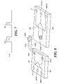
- FIG. 8 is a diagrammatic illustration of an isolator according to some aspects of the invention, wherein the primary winding is a top winding;
- FIG. 9 is an illustration of input and output waveforms when driving a micro-transformer of the type preferably employed in implementing embodiments of the isolators taught herein, particularly illustrating the difference between driving top and bottom transformer windings;
- FIG. 10 is a diagrammatic illustration of an isolator according to some aspects of the invention, wherein the primary winding is a bottom winding;
- FIG. 11 is a diagrammatic illustration of a bi-directional dual channel isolator such as may be implemented using the teachings herein;
- FIG. 12 is a simplified schematic circuit diagram for a supply-independent delay element for use in a pulse generator (transmitter) in isolators such as are taught herein;
- FIGS. 13 and 14 are simplified schematic circuit diagrams for current sources for use in the delay element of FIG. 12 ;
- FIG. 15 is a highly schematic block diagram showing an embodiment of a logic signal isolator in accordance with the subject invention.
- FIGS. 16A-16D are schematic timing diagrams showing the various signals processed and produced by the logic isolator of FIG. 15 ;
- FIG. 17 is a schematic circuit diagram showing an example of a logic signal isolator in accordance with the subject invention.
- FIG. 18 is a schematic circuit diagram of an example of a logic gate used in the circuit of FIG. 17 .
- Micro-transformer based digital isolators have been developed in recent years by applicants and their colleagues. This genus of digital isolators shows dramatic improvements over traditional opto-isolators in terms of speed, power, edge symmetry and cost.
- the transmission methods employed in these micro-transformer based digital isolators fall into two main categories. The first category is based on edge detection; the second, on level detection. Those designs that are based on edge detection have the advantage of lower power, lower pulse width distortion and higher common mode transient immunity over those based on level detection. Typically, implementations based on edge detection require two transmitters, two receivers and two transformers to make a single channel isolator. A need exists for a less expensive design.
- a digital isolator may be formed, which is based on a micro-transformer-created isolation barrier, using only a single transmitter, a single receiver and a single transmitter.
- This approach dramatically reduces the die cost while still preserving the merits of edge detection.
- the present invention enables bi-directional signal transfer. That is, the signal can be transferred from the top coil to the bottom coil or from the bottom coil to the top coil. This capability can be leveraged to make bi-directional, multi-channel signal isolators or to program the channel direction of a single data channel.
- This invention preserves the main advantages of high speed, low power, high common-mode immunity and adds to them a reduction in size and enhanced ease of integration.
- micro-transformer there is meant transformer formed in, partially in, or on, a semiconductor substrate of flat, parallel conductive windings and having no magnetic core. These transformers are also referred to as “air-core” transformers though there actually will be more than air between the windings, typically one or more layers of dielectric materials.
- FIG. 1 A block diagram of a typical prior art example of a transformer-based isolator for digital signals is shown in FIG. 1 .
- the isolator 100 comprises (after an optional, though preferable, glitch filter 101 ), a pair of edge detectors 102 and 104 , edge detector 104 being driven by the logical complement to the signal driving edge detector 102 , by means of inverter 106 .
- the output of edge detector 102 provides a pulse, the SET_HI signal to the primary winding of transformer 108 responsive to detection of a low-to-high transition (i.e., a leading edge) in the output of the glitch filter 101 .
- the secondary winding of transformer 108 is connected to the set input of a flip-flop 110 .
- the output of edge detector 104 is a pulse named the SET_LO signal which is supplied to the primary winding 120 A of transformer 120 responsive to detection of a high-to-low transition (i.e., a falling edge) in the output of the glitch filter 101 .
- the secondary winding of transformer 120 is supplied to the reset input of flip-flop 110 .
- the connection from each transformer secondary winding to the flip-flop 110 is not direct, but is made through a Schmitt trigger or other waveform-shaping circuitry intended to provide clean, fast transitions to the flip-flop.
- the primary windings 108 A and 120 A of transformers 108 and 120 are connected (referenced) to a first electrical ground, GNDA, while the secondary windings 108 A and 120 B, together with the flip-flop 110 , are referenced to a second electrical ground, GNDB, which is isolated from the first ground.
- the outputs of the edge detectors 102 and 104 comprise encoded leading edge and falling edge indicators. These indicators may be in the form of pulses, short bursts, or any periodic signal. So, the edge detectors may be monostable multivibrators, differentiators or other suitable circuits. In the illustration, a single pulse of about ins duration is shown as an edge indicator signal.
- Glitch filter 101 may be of any suitable design.
- a brick wall filter is typical. Typically, it should have a bandwidth larger than that to which the edge detectors respond.
- FIG. 2 provides a schematic circuit diagram for a usable filter, corresponding timing diagrams showing the waveforms at the input, nodes A-D and the filter output being provided in FIG. 3 .
- the filtered pulse width is given approximately by CVthreshold/i, where Vthreshold is the threshold voltage of the Schmitt triggers 22 and 24 and i is the current from current sources 26 , 28 .
- FIG. 4 illustrates a logic signal isolator 200 in which encoded leading and falling edge indicators from a pair of edge detectors 202 and 204 (corresponding to edge detectors 102 and 104 of FIG. 1 ) are sent to a single transformer 210 .
- the leading edge and falling edge indicators are encoded as different, distinguishable signals. That is, the SET_HI signal output from leading edge detector 202 is distinct from the SET_LO signal output from falling edge detector 204 .
- the receiving side circuitry connected to the secondary winding 210 B of transformer 210 (again, typically via a Schmitt trigger or other suitable wave-shaping circuit, not show) then reconstructs the logic edges based on distinguishing between those two signals.
- edge detector 202 produces two consecutive short pulses 232 and 234 as a leading edge indicator and edge detector 204 produces only a single pulse 236 as a falling edge indicator.
- the pulses 232 and 234 preferably have a known, fixed spacing between them. If transformer 210 is a high bandwidth micro-transformer, the pulse widths may be as narrow as 1 ns or even less.
- the outputs of edge detectors 202 and 204 are combined by and OR gate 240 , to drive the primary winding 210 A of the transformer. The pulses cannot be so short or weak in amplitude that the OR gate will not respond properly.
- the concept is to use two different, distinguishable signals. They need not be a single pulse and a double pulse. For example, a narrow pulse (e.g., 1 ns) could be used as one edge indicator and a wider pulse (e.g., 2 ns) could be used as the other edge indicator. It is only necessary that the receiver be able to distinguish the two signals.
- the concept lends itself to the use of other distinguishable signals but at the same time, one would not wish to use an unnecessarily complicated arrangement or one which would add any significant delay in signal processing. For signals other than those illustrated, it might be necessary to replace OR gate 240 with other elements that would effectively combine the outputs of the edge detectors into a single signal for driving the transformer.
- the two pulses in the SET_HI signal have a known, fixed spacing between them.
- the total duration of the two pulses and the intervening gap between them in the SET-HI signal if sufficiently short with respect to the shortest interval between two leading edges in the input signal, will permit resolution between the SET-HI and SET_LO pulses.
- a receiver circuit 250 connected to secondary winding 210 B, recovers the output of transformer 210 , distinguishes between the SET_HI and SET_LO pulses, and reconstructs the input logic signal as a data out signal. More specifically, the received pulses at node 252 clock a D-type flip-flop 254 and also act as the input to a non-retriggerable edge-triggered mono-stable multivibrator 256 .
- the multivibrator 256 puts out a pulse on line 258 that is of duration at least as long as the combination of pulse 232 and the interval between pulse 232 and pulse 234 in the SET_HI signal.
- the pulse on line 258 should be at least about 2 ns long; 3 ns is used in this example to allow some “hold” time to facilitate clocking of flip-flop 254 .
- Line 258 connects to the D input of flip-flop 254 , to the reset input of that flip-flop and to the input of inverter 262 .
- the output of inverter 262 is connected to the input of an edge detector 264 and the QB output (the complementary output) of flip-flop 254 is connected to the input of another edge detector 266 .
- the output of edge detector 264 is connected to one input of each of AND gates 272 and 274 .
- edge detector 266 is connected to the second input of AND gate 272 and through inverter 276 to the second input of AND gate 274 .
- the output of AND gate 272 is connected to the set input of set/reset flip-flop 278 and the output of AND gate 274 is connected to the reset input of flip-flop 278 .
- the DATA OUT signal corresponding to an isolated and slightly delayed version of the DATA IN signal received by the glitch filter, appears at the Q output of flip-flop 278 .
- the operation of this circuit will now be explained with reference to the waveforms of FIG. 5 .
- the COIL signal is received.
- Pulses 232 and 234 have been generated by edge detector (i.e., transmitter) 202 in response to the leading, positive-going edge of the input signal and pulse 236 has been generated by edge detector 204 in response to the negative-going, trailing edge of the input signal.
- the edge-triggered mono-stable (ETMS) multivibrator 256 generates an output waveform on line 258 as shown at ETMS. In the ETMS signal, the leading edge of pulse 232 causes the pulse 304 to be generated.
- ETMS edge-triggered mono-stable
- the multivibrator 256 does not do anything in response to the falling edge of pulse 232 or to either edge of the second pulse 234 . Only after pulse 304 has been output is the multivibrator 256 able to respond to a new input, which it does when it receives the leading edge of pulse 236 . Detection of the leading edge of pulse 236 causes the outputting of pulse 306 .
- the second of the two initial pulses, pulse 234 is detected and the output signal is formed as follows.
- the D input of the flip-flop 254 still sees a low output from the edge-triggered mono-stable multivibrator on line 258 . That means the QB output of the flip-flop 254 is set to a high value and the Q output is set to a low value.
- the output of the edge-triggered mono-stable is now high and the QB output of flip-flop 254 transitions to a low value, meaning that the Q output of flip-flop 254 goes high as at the leading edge of the pulse 308 in the “2 Pulse Detect” signal on FIG. 5 .
- This H-L edge is sensed by edge detector 266 , which produces a pulse 310 to the second (bottom) input of AND gate 272 .
- the output of the edge-triggered mono-stable is also supplied to the input of inverter 262 .
- edge detector 264 sees a high-to-low transition (edge) at the output of inverter 262 and responsively generates a positive-going pulse 312 to the first (top) input of AND gate 272 and to a first (top) input of AND gate 274 .
- Inverter 262 is designed to have a propagation delay that is substantially equal to that from the D input to the QB output of flip-flop 254 .
- edge detectors 264 and 266 produce substantially concurrent output pulses 310 and 312 to AND gate 272 .
- the output 314 of AND gate 272 goes from low to high at the same time and sets the set (S) input of the SR flip-flop 278 ; and the Q output thereof, being the DATA OUT signal, goes high.
- the second (bottom) input of AND gate 274 is responsive to the output of edge detector 266 through inverter 276 , the first and second pulses have no impact on the output of AND gate 274 and do not affect the output of flip-flop 278 .
- third pulse 236 triggers edge-triggered mono-stable 256 , to produce its second output pulse 306 , this results as stated above, in the generation of a pulse at the output of edge detector 264 upon the falling edge of the mono-stable output pulse.
- FIG. 6 An alternative embodiment 200 ′ for the pulse receiver circuitry is shown in FIG. 6 .
- Edge detectors 264 , 266 and gates 272 , 274 and 276 have been eliminated and the output flip-flop 278 ′ is changed from a set-reset flip-flop to a D-type flip-flop.
- the first pulse 232 clocks flip-flop 254 before the edge-triggered mono-stable 256 has generated an output pulse on the D input of flip-flop 278 ′. Therefore, the Q output of flip-flop 254 assumes a low state.
- the second pulse 234 clocks flip-flop 254 , the D input thereof now sees the output pulse 304 from the edge-triggered mono-stable and the Q output of flip-flop 254 transitions to a high value.
- the falling edge of the mono-stable pulse 304 is coupled to the clock input of flip-flop 278 ′ through inverter 262 , and clocks flip-flop 278 ′; as a result, the high value from the Q output of flip-flop 254 supplies a high value on the Q output of flip-flop 278 ′, and the DATA OUT signal.
- the falling edge of the mono-stable output pulses also reset flip-flop 254 via its RB (i.e., R complement) input.
- the output flip-flop 278 ′ is next clocked, again, by the falling edge of the output pulse from the mono-stable, being edge 306 B, of pulse 306 generated in response to the third pulse, 236 , on the transformer.
- flip-flop 254 has been reset to have a low output and the output of flip-flop 278 ′ accordingly goes low.
- a reset signal termed PWReset_B is supplied to the reset (complement) input of flip-flop 278 ′ and causes flip-flop 278 ′ to be reset whenever device power is reset.
- FIG. 7 An alternative signaling arrangement, mentioned above, is shown in FIG. 7 .
- a double-width pulse 350 is used to indicate a rising edge and a single-width pulse 360 is used to indicate a falling edge.
- Those skilled in the art of electrical engineering will readily be able to device logic circuitry to discriminate between a pulse of single width duration ⁇ and a pulse of double width duration 2 ⁇ .
- FIG. 8 An exemplary physical implementation for an isolator according to the present invention, capable of being packaged in an integrated circuit form, is shown in FIG. 8 .
- a transmitter (or driver) circuit 802 is formed on a first substrate 804 .
- a transformer comprising a first winding 806 A and a second winding 806 B is formed on a second substrate 808 , along with a receiver circuit 810 .
- Wire leads 812 A, 812 B from bond pads 814 A and 814 B on substrate 804 connect the driver output to the primary winding 806 A of the transformer.
- the primary (driving) coil winding is the top coil 806 A and the secondary (receiving) coil winding is the bottom coil 806 B. It is important to note that the two coils, even if made in the same dimensions and geometry, will exhibit different quality factor Q, because the bottom coil has higher capacitance to substrate 808 .
- the damping network consists of a resistor 922 and a capacitor 924 in series. Damping with a resistor only would dramatically reduce the received signal and typically would not be acceptable.
- the capacitor 924 has very low impedance at high frequencies and blocks DC current through the damping resistor, providing the desired response characteristics. Note that with the damping network, the received waveform 926 from the top coil is substantially the same as the received waveform from the bottom coil as shown at 908 in FIG. 9A .
- the edge-detection based isolator above described can be implemented as pictured in FIG. 10 .
- the primary coil is the bottom coil 906 instead of the top coil 904 .
- a bi-directional dual isolator arrangement as shown in FIG. 11 is thus enabled.
- This bi-directional isolator has a pair of stacked transformers arranged side by side.
- a first transformer is formed by the windings 1102 A and 1102 B, while a second transformer is formed by the windings 1104 A and 1104 B.
- Only one substrate 1106 carries the transformer structure because the primary winding now can be the top coil or bottom coil of a transformer. Absent this possibility, each of the two substrates 1106 and 1108 would need to have an isolated transformer structure thereon and the product would be considerably more expensive to make.
- signals can be transmitted bi-directionally concurrently through a single transformer.
- single- and multiple-channel isolators can be manufactured so that the selection of configuration (i.e., which channels transmit in which directions) can be made in final assembly and test steps of production. That lowers product cost by allowing one product core to be made and sold for multiple configurations.
- configuration i.e., which channels transmit in which directions
- the designs shown above lend themselves to this approach in one of two ways.
- a logic isolator comprises a micro-transformer having, on a substrate, vertically stacked, a bottom winding and a top winding disposed over and insulated from the bottom winding; a damping network connected across the top winding; a transmitter circuit receiving a logic input signal and providing a transformer driving signal; a receiving circuit connected to receive from the transformer a signal corresponding to the driving signal and generating an output comprising a reconstituted logic input signal; and means for programming the isolator by coupling the driving signal to a selected one of the windings and coupling the receiving circuit to the other one of the windings.
- the programming would have to be effected before final testing of the isolator in order to maintain isolation between input and output.
- the means for programming may, for example, comprise a fusible connection(s) programmed by blowing open a conductive path(s).
- the means for programming alternatively may comprise bond wires provided between the transformer windings on the one hand and the transmitter and receiving circuits, on the other hand. In either instance, the isolator cannot be tested until isolation-destroying paths are blown open or isolation-destroying bond wires are removed (if there had been any); of course, bond wires could selectively be installed as the last step in manufacture, before testing.
- the means for programming may comprise programmable circuitry configurable to connect the transmitter circuit to either the top winding or the bottom winding and to connect the receiving circuit to the other winding. Again, however, only one set of valid connections can be established if input-output isolation is to be maintained.
- the programmable circuitry may include programmable switching circuits and a memory containing programming to control the switching circuits. The memory may be read-only memory.
- a second approach may be based on providing modules, each having both a transformer-driving circuit (i.e., transmitter) and a receiver circuit, such that the module is configured to operate only as a driving circuit or only as a receiving circuit, configuring done at final assembly or by the user.
- a logic isolator comprises a micro-transformer having, on a substrate, vertically stacked, a bottom winding and a top winding disposed over and insulated from the bottom winding; a damping network connected across the top winding; a first module coupled to the top winding capable of either receiving a logic input signal and providing a transformer driving signal or receiving from the transformer a signal corresponding to the driving signal and generating an output comprising a reconstituted logic input signal; a second module coupled to the bottom winding capable of either receiving a logic input signal and providing a transformer driving signal or receiving from the transformer a signal corresponding to the driving signal and generating an output comprising a reconstituted logic input signal; and means for programming the isolator such that the first module operates in the transformer drive mode while the second circuit operates in the receive mode or that the first module operates in the receive mode while the second module operates in the transformer drive mode.
- Such means may comprise, for example, at least one fusible connection programmed by blowing open at least one conductive path.
- the means for programming may comprise one or more bond wires provided between the transformer windings on the one hand and the first and second modules, on the other hand.
- the means for programming also may comprise programmable circuitry configurable to connect the first module to either the top winding or the bottom winding and to connect the second module to the other winding.
- Such programmable circuitry may include programmable switching circuits and a memory containing programming to control the switching circuits.
- the memory may include a read-only memory.
- a dual-channel, bi-directional isolator comprises first and second micro-transformers arranged on a first substrate, each transformer having a top winding and a bottom winding.
- a first transmitter circuit is connected to drive the bottom winding of the first transformer; a second transmitter circuit is connected to drive the top winding of the second transformer.
- a first receiver circuit is connected to receive signals from the bottom winding of the second transformer.
- a second receiver circuit is connected to receive signals from the top winding of the first transformer.
- the first transmitter circuit and first receiver circuit are on the first substrate, and the second transmitter circuit and second receiver circuit are on a second substrate which is electrically isolated from the first substrate.
- a single channel bi-directional isolator comprising a micro-transformer arranged on a first substrate, the transformer having a top winding and a bottom winding; a first transmitter circuit connected to drive the bottom winding; a second transmitter circuit connected to drive the top winding; a first receiver circuit connected to receive signals from the top winding; a second receiver circuit connected to receive signals from the bottom winding; and the first and second transmitter circuits transmitting so as to avoid interfering with each other.
- the first transmitter circuit and the second receiver circuit are on the first substrate and the second transmitter circuit and the first receiver circuit are on a second substrate which is electrically isolated from the first substrate.
- a delay element typically is required in such pulse generators.
- a delay element 1200 comprises two current sources 1202 and 1204 which supply currents I 1 and I 2 , respectively, one capacitor, C, and one switching element such as an inverter or a Schmitt trigger 1206 .
- current source 1202 for generating current I 1 is shown in FIG. 13 .
- current source 1202 comprises a single transistor 1212 and a resistor R.
- the resistor R has one end connected to the supply voltage VDD and the other end connected to the drain of transistor 1212 .
- Current I 1 (VDD ⁇ VT)/R, where VT is the threshold voltage of the MOS transistor 1212 .
- Current source 1204 for generating current I 2 can be easily implemented. For example, a simplified schematic circuit diagram for such a current source is shown in FIG. 14 .
- Transistor 1214 imposes the voltage VT across resistor R, inducing current I 2 and that current is mirrored in the drain path of transistor 1214 .
- the delay element 1200 can be easily used to generate pulses whose width is independent of the supply voltage.
- the illustrated design need not be used to form the required current source. Any design can be used that will produce a supply-independent pulse width. In the examples shown, this is achieved by adding a first current that is proportional to the supply voltage to a second current that is inversely proportional to the supply voltage. Other approaches are not ruled out.
- a driver or transmitter circuit 2000 , FIG. 15 is responsive to a first type of edge, e.g., a rising edge 2004 a , FIG. 16A of an input signal and generates a first high amplitude signal 2006 a , FIG. 16B supplied to the primary winding of transformer 2002 , FIG. 15 .
- driver circuit 2000 , FIG. 15 In response to falling edge 2004 b , FIG. 16A of the input signal, driver circuit 2000 , FIG. 15 generates lower amplitude signal 2006 b , FIG. 16B supplied to the primary winding of the transformer.
- Receiver circuit 2008 receives, as shown FIG. 16C , corresponding first high and second low amplitude signals 2006 a ′ and 2006 b ′ from the secondary winding and reconstructs the logic input signal as shown in FIG. 16D as an output of the signal isolator.
- driver circuit 2000 is configured as shown in FIG. 17 .
- Differentiator 2010 a generates pulse 2012 a in response to rising edge 2004 a of the input signal and differentiator 2010 b generates a pulse 2012 b in response to falling edge 2004 b of the input signal.
- OR gate 2014 is responsive to a high voltage V 1 and to a low voltage V 2 .
- gate 2014 In response to pulse 2012 a and high voltage V 1 , gate 2014 generates higher amplitude pulse 2006 a .
- pulse 2012 b and lower voltage source V 2 gate 2014 generates lower amplitude pulse 2006 b .
- Pulses 2006 a and 2006 b are supplied to primary 2016 of micro-transformer 2002 and, as noted above, corresponding pulses 2006 a ′ and 2006 b ′ are output by secondary 2018 .
- Receiver circuit 2008 in this example, includes threshold detector 2020 a tied to a high reference and threshold detector 2020 b tied to a low reference. In this way, threshold detector 2020 a produces an output in response to high amplitude pulse 2006 a ′ and threshold detector 2020 b produces an output in response to both high amplitude pulse 2006 a and lower amplitude pulse 2006 b .
- NOR gate 2022 is response to both threshold detectors and produces a high signal only when no pulses are input thus recreating the input logic signal.
- transmitter circuit 2000 may include glitch filter 2030 as described above with reference to FIG. 1 .
- transmitter circuit 2000 may include refresh circuit 2040 configured to periodically send a refresh signal across micro-transformer 2002 .
- a stable 2042 through differentiator 2044 will generate a refresh signal 2006 a when the input is high and neither an edge 2004 a nor an edge 2004 b was detected for 1 us.
- a stable 2042 will generate a refresh signal 2006 b when the input is low and neither an edge 2004 a nor an edge 2004 b was detected.
- the refresh signals are generated to ensure the output is always updated.
- gate 2014 is configured as shown in FIG. 18 .
- Gate 2014 is similar to a normal OR gate except that PMOS 2080 a and PMOS 2080 b have their source tied to different power supplies, one to V 1 and one to V 2 .
- a higher speed isolator is realized in only a single channel.
- a single pulse with two different amplitudes can be used to differentiate the rising edge from the falling edge of the input signal which is easier to decode since the input signal is recovered based on different pulse amplitudes.
Abstract
Description
Claims (17)
Priority Applications (1)
| Application Number | Priority Date | Filing Date | Title |
|---|---|---|---|
| US12/009,766 US7719305B2 (en) | 2006-07-06 | 2008-01-22 | Signal isolator using micro-transformers |
Applications Claiming Priority (2)
| Application Number | Priority Date | Filing Date | Title |
|---|---|---|---|
| US11/481,997 US7692444B2 (en) | 2003-04-30 | 2006-07-06 | Signal isolators using micro-transformers |
| US12/009,766 US7719305B2 (en) | 2006-07-06 | 2008-01-22 | Signal isolator using micro-transformers |
Related Parent Applications (1)
| Application Number | Title | Priority Date | Filing Date |
|---|---|---|---|
| US11/481,997 Continuation-In-Part US7692444B2 (en) | 2003-04-30 | 2006-07-06 | Signal isolators using micro-transformers |
Publications (2)
| Publication Number | Publication Date |
|---|---|
| US20080136442A1 US20080136442A1 (en) | 2008-06-12 |
| US7719305B2 true US7719305B2 (en) | 2010-05-18 |
Family
ID=39497209
Family Applications (1)
| Application Number | Title | Priority Date | Filing Date |
|---|---|---|---|
| US12/009,766 Active 2026-07-31 US7719305B2 (en) | 2006-07-06 | 2008-01-22 | Signal isolator using micro-transformers |
Country Status (1)
| Country | Link |
|---|---|
| US (1) | US7719305B2 (en) |
Cited By (31)
| Publication number | Priority date | Publication date | Assignee | Title |
|---|---|---|---|---|
| US20080179963A1 (en) * | 2006-08-28 | 2008-07-31 | Avago Technologies Ecbu (Singapore) Pte. Ltd. | Galvanic Isolators and Coil Transducers |
| US20090195082A1 (en) * | 2008-02-04 | 2009-08-06 | Baoxing Chen | Solid state relay |
| US20100148911A1 (en) * | 2007-05-10 | 2010-06-17 | Avago Technologies Ecbu Ip (Singapore) Pte. Ltd. | Miniature Transformers Adapted For Use In Galvanic Isolators And The like |
| US20100176660A1 (en) * | 2006-08-28 | 2010-07-15 | Avago Technologies General IP (Singpore) Pte. Ltd. | Galvanic isolator |
| US20100259909A1 (en) * | 2006-08-28 | 2010-10-14 | Avago Technologies Ecbu (Singapore) Pte. Ltd. | Widebody Coil Isolators |
| US20110075449A1 (en) * | 2008-03-31 | 2011-03-31 | Avago Technologies Ecbu Ip (Singapore) Pte. Ltd. | Compact Power Transformer Components, Devices, Systems and Methods |
| US20110156812A1 (en) * | 2009-12-31 | 2011-06-30 | Avago Technologies Wireless Ip (Singapore) Pte. Ltd. | Multi-band, multi-mode rf transmit amplifier system with separate signal paths for linear and saturated operation |
| US20110174999A1 (en) * | 2010-01-21 | 2011-07-21 | William French | Galvanic isolation that incorporates a transformer with an optical link and that can be integrated onto a single semiconductor substrate |
| US20110222316A1 (en) * | 2008-11-27 | 2011-09-15 | Toyota Jidosha Kabushiki Kaisha | Electrically insulated switching element driver and method for controlling same |
| US20120002377A1 (en) * | 2010-06-30 | 2012-01-05 | William French | Galvanic isolation transformer |
| US8374003B2 (en) | 2010-06-11 | 2013-02-12 | Murata Manufacturing Co., Ltd. | Isolated switching power supply apparatus |
| US8385043B2 (en) | 2006-08-28 | 2013-02-26 | Avago Technologies ECBU IP (Singapoare) Pte. Ltd. | Galvanic isolator |
| US8497700B2 (en) | 2011-10-21 | 2013-07-30 | Samsung Electro-Mechanics | Systems and methods for propagating digital data across an isolation barrier |
| US8558344B2 (en) | 2011-09-06 | 2013-10-15 | Analog Devices, Inc. | Small size and fully integrated power converter with magnetics on chip |
| CN103731038A (en) * | 2012-10-11 | 2014-04-16 | 富士电机株式会社 | Signal transmission device and switching power supply |
| US8786393B1 (en) | 2013-02-05 | 2014-07-22 | Analog Devices, Inc. | Step up or step down micro-transformer with tight magnetic coupling |
| US8829955B1 (en) | 2013-03-14 | 2014-09-09 | Analog Devices, Inc. | Isolator-based transmission system with side isolator channel for refresh signals |
| US8928383B2 (en) | 2013-03-15 | 2015-01-06 | Analog Devices, Inc. | Integrated delayed clock for high speed isolated SPI communication |
| US20150180228A1 (en) * | 2013-12-19 | 2015-06-25 | Silicon Laboratories Inc. | Suppression of transients in communications across an isolation barrier |
| US9105391B2 (en) | 2006-08-28 | 2015-08-11 | Avago Technologies General Ip (Singapore) Pte. Ltd. | High voltage hold-off coil transducer |
| US9293997B2 (en) | 2013-03-14 | 2016-03-22 | Analog Devices Global | Isolated error amplifier for isolated power supplies |
| US9525411B2 (en) | 2014-11-13 | 2016-12-20 | Analog Devices, Inc. | Power supply circuits for gate drivers |
| US9531253B2 (en) | 2014-01-30 | 2016-12-27 | Silicon Laboratories Inc. | Soft-start for isolated power converter |
| US9531284B2 (en) | 2014-01-30 | 2016-12-27 | Silicon Laboratories Inc. | Pseudo-constant frequency control for voltage converter |
| US9660848B2 (en) | 2014-09-15 | 2017-05-23 | Analog Devices Global | Methods and structures to generate on/off keyed carrier signals for signal isolators |
| US9998301B2 (en) | 2014-11-03 | 2018-06-12 | Analog Devices, Inc. | Signal isolator system with protection for common mode transients |
| US10270630B2 (en) | 2014-09-15 | 2019-04-23 | Analog Devices, Inc. | Demodulation of on-off-key modulated signals in signal isolator systems |
| US10277278B2 (en) | 2014-09-24 | 2019-04-30 | Analog Devices, Inc. | Circuits and systems for multiplexed isolator communication |
| US10290608B2 (en) | 2016-09-13 | 2019-05-14 | Allegro Microsystems, Llc | Signal isolator having bidirectional diagnostic signal exchange |
| US10536309B2 (en) | 2014-09-15 | 2020-01-14 | Analog Devices, Inc. | Demodulation of on-off-key modulated signals in signal isolator systems |
| US11115244B2 (en) | 2019-09-17 | 2021-09-07 | Allegro Microsystems, Llc | Signal isolator with three state data transmission |
Families Citing this family (7)
| Publication number | Priority date | Publication date | Assignee | Title |
|---|---|---|---|---|
| US8432182B2 (en) * | 2009-03-30 | 2013-04-30 | Analog Devices, Inc. | USB isolator with advanced control features |
| JP6368111B2 (en) * | 2013-06-07 | 2018-08-01 | ローム株式会社 | Signal transmission device |
| US9379746B2 (en) * | 2014-06-30 | 2016-06-28 | Texas Instruments Incorporated | Isolation circuits for digital communications and methods to provide isolation for digital communications |
| US9941999B1 (en) * | 2017-03-08 | 2018-04-10 | Allegro Microsystems, Llc | Methods and apparatus for communication over an isolation barrier with monitoring |
| DE102017126635B4 (en) | 2017-11-13 | 2020-10-08 | Infineon Technologies Ag | Microelectromechanical light emitter component and method for producing a microelectromechanical light emitter component |
| US10978135B2 (en) * | 2019-02-28 | 2021-04-13 | Texas Instruments Incorporated | Architecture for resolution of data and refresh-path conflict for low-power digital isolator |
| CN110601680A (en) * | 2019-08-22 | 2019-12-20 | 宜宾市叙芯半导体有限公司 | Edge switching circuit and switching method of integrated magnetic isolation chip |
Citations (101)
| Publication number | Priority date | Publication date | Assignee | Title |
|---|---|---|---|---|
| US3058078A (en) | 1956-02-21 | 1962-10-09 | Siegfried R Hoh | Low capacitance transformer |
| US3537022A (en) | 1968-01-10 | 1970-10-27 | Hewlett Packard Co | Signal translating circuit |
| US3714540A (en) | 1970-11-10 | 1973-01-30 | Oxy Metal Finishing Corp | Isolation and transforming circuit |
| US3760198A (en) | 1970-11-06 | 1973-09-18 | Yokogawa Electric Works Ltd | Circuitry for transmitting pulses with ground isolation but without pulse waveform distortion |
| US3798608A (en) | 1972-12-15 | 1974-03-19 | Johnson Service Co | Digital signal transmission apparatus |
| US3808673A (en) | 1971-03-17 | 1974-05-07 | Monsanto Co | Opto-isolator devices and method for the fabrication thereof |
| DE2529296A1 (en) | 1975-07-01 | 1977-01-20 | Ferranti Ltd | Isolating transformer used as pulse transformer - is for use with high speed pulses and has two annular cores covered in windings |
| US4024452A (en) | 1976-03-10 | 1977-05-17 | Bell Telephone Laboratories, Incorporated | Integrated solid state isolator circuit |
| US4027152A (en) | 1975-11-28 | 1977-05-31 | Hewlett-Packard Company | Apparatus and method for transmitting binary-coded information |
| US4118603A (en) | 1977-05-31 | 1978-10-03 | Noramco, Inc. | DC signaling circuit for use in conjunction with isolation transformers |
| US4159431A (en) | 1977-02-18 | 1979-06-26 | Robert Bosch Gmbh | Electronic switch maintaining a predetermined state independent of supply voltage variation |
| US4227045A (en) | 1978-06-28 | 1980-10-07 | Honeywell Inc. | Data processing protocol system |
| US4275404A (en) | 1979-10-05 | 1981-06-23 | Bell Telephone Laboratories, Incorporated | Monolithic opto-isolator |
| US4302807A (en) | 1980-08-04 | 1981-11-24 | Burroughs Corporation | Controlled current base drive circuit |
| US4538136A (en) | 1981-03-30 | 1985-08-27 | Amtel Systems Corporation | Power line communication system utilizing a local oscillator |
| US4547961A (en) | 1980-11-14 | 1985-10-22 | Analog Devices, Incorporated | Method of manufacture of miniaturized transformer |
| GB2173956A (en) | 1985-03-29 | 1986-10-22 | Plessey Co Plc | Integrated electrical transformer |
| US4660014A (en) | 1985-06-19 | 1987-04-21 | Jaycor | Electromagnetic pulse isolation transformer |
| US4703283A (en) | 1986-02-24 | 1987-10-27 | Howard Samuels | Isolation amplifier with T-type modulator |
| US4748419A (en) * | 1986-04-28 | 1988-05-31 | Burr-Brown Corporation | Isolation amplifier with precise timing of signals coupled across isolation barrier |
| EP0282102A2 (en) | 1987-03-12 | 1988-09-14 | The Boeing Company | Binary data communication system |
| US4780795A (en) | 1986-04-28 | 1988-10-25 | Burr-Brown Corporation | Packages for hybrid integrated circuit high voltage isolation amplifiers and method of manufacture |
| US4785345A (en) | 1986-05-08 | 1988-11-15 | American Telephone And Telegraph Co., At&T Bell Labs. | Integrated transformer structure with primary winding in substrate |
| US4818855A (en) | 1985-01-11 | 1989-04-04 | Indala Corporation | Identification system |
| US4817865A (en) | 1988-03-17 | 1989-04-04 | Racal Data Communications Inc. | Ventilation system for modular electronic housing |
| US4835486A (en) | 1986-04-28 | 1989-05-30 | Burr-Brown Corporation | Isolation amplifier with precise timing of signals coupled across isolation barrier |
| US4859877A (en) | 1988-01-04 | 1989-08-22 | Gte Laboratories Incorporated | Bidirectional digital signal transmission system |
| US4885582A (en) | 1987-09-28 | 1989-12-05 | The Grass Valley Group, Inc. | "Simple code" encoder/decoder |
| US4922883A (en) | 1987-10-29 | 1990-05-08 | Aisin Seiki Kabushiki Kaisha | Multi spark ignition system |
| US4924210A (en) | 1987-03-17 | 1990-05-08 | Omron Tateisi Electronics Company | Method of controlling communication in an ID system |
| US4937468A (en) | 1989-01-09 | 1990-06-26 | Sundstrand Corporation | Isolation circuit for pulse waveforms |
| US4945264A (en) | 1989-01-05 | 1990-07-31 | Acer Incorporated | Interface control circuit with active circuit charge or discharge |
| US4959631A (en) | 1987-09-29 | 1990-09-25 | Kabushiki Kaisha Toshiba | Planar inductor |
| US5041780A (en) | 1988-09-13 | 1991-08-20 | California Institute Of Technology | Integrable current sensors |
| US5057968A (en) | 1989-10-16 | 1991-10-15 | Lockheed Corporation | Cooling system for electronic modules |
| US5095357A (en) | 1989-08-18 | 1992-03-10 | Mitsubishi Denki Kabushiki Kaisha | Inductive structures for semiconductor integrated circuits |
| US5102040A (en) | 1991-03-28 | 1992-04-07 | At&T Bell Laboratories | Method and apparatus for fan control to achieve enhanced cooling |
| US5128729A (en) | 1990-11-13 | 1992-07-07 | Motorola, Inc. | Complex opto-isolator with improved stand-off voltage stability |
| US5142432A (en) | 1991-10-21 | 1992-08-25 | General Motors Corporation | Fault detection apparatus for a transformer isolated transistor drive circuit for a power device |
| US5164621A (en) | 1990-11-06 | 1992-11-17 | Mitsubishi Denki Kabushiki Kaisha | Delay device including generator compensating for power supply fluctuations |
| US5204551A (en) | 1991-07-01 | 1993-04-20 | Motorola, Inc. | Method and apparatus for high power pulse modulation |
| FR2679670B1 (en) | 1991-07-23 | 1993-10-29 | Dan Serbanescu | CONTACTLESS BILATERAL COMMUNICATION SYSTEM FOR MICROPROCESSOR CREDIT CARDS. |
| US5270882A (en) | 1992-07-15 | 1993-12-14 | International Business Machines Corporation | Low-voltage, low-power amplifier for magnetoresistive sensor |
| US5293400A (en) | 1990-05-18 | 1994-03-08 | Centre National Du Machinisme Agricole, Du Genie Rural, Des Eaux Et Des Forets | Contactless linking device for interconnecting data bus sections |
| US5334882A (en) | 1992-12-14 | 1994-08-02 | National Semiconductor | Driver for backplane transceiver logic bus |
| US5353001A (en) | 1991-01-24 | 1994-10-04 | Burr-Brown Corporation | Hybrid integrated circuit planar transformer |
| US5369666A (en) | 1992-06-09 | 1994-11-29 | Rockwell International Corporation | Modem with digital isolation |
| US5384808A (en) * | 1992-12-31 | 1995-01-24 | Apple Computer, Inc. | Method and apparatus for transmitting NRZ data signals across an isolation barrier disposed in an interface between adjacent devices on a bus |
| US5396394A (en) | 1990-02-06 | 1995-03-07 | International Business Machines Corp. | ISDN device line protection circuit |
| US5469098A (en) | 1993-03-29 | 1995-11-21 | Exide Electronics Corporation | Isolated gate drive |
| US5467607A (en) | 1994-02-22 | 1995-11-21 | At&T Corp. | Air conditioning control system |
| US5484012A (en) | 1994-03-15 | 1996-01-16 | Fujitsu Limited | Electronic apparatus having cooling system |
| US5533054A (en) | 1993-07-09 | 1996-07-02 | Technitrol, Inc. | Multi-level data transmitter |
| US5539241A (en) | 1993-01-29 | 1996-07-23 | The Regents Of The University Of California | Monolithic passive component |
| US5539598A (en) | 1994-12-08 | 1996-07-23 | International Business Machines Corporation | Electrostatic protection for a shielded MR sensor |
| US5572179A (en) | 1992-05-27 | 1996-11-05 | Fuji Electric Co., Ltd. | Thin film transformer |
| US5588021A (en) | 1992-09-25 | 1996-12-24 | Light & Sound Design Limited | Repeater for use in a control network |
| US5596466A (en) | 1995-01-13 | 1997-01-21 | Ixys Corporation | Intelligent, isolated half-bridge power module |
| US5650357A (en) | 1992-12-03 | 1997-07-22 | Linear Technology Corporation | Process for manufacturing a lead frame capacitor and capacitively-coupled isolator circuit using same |
| US5701037A (en) | 1994-11-15 | 1997-12-23 | Siemens Aktiengesellschaft | Arrangement for inductive signal transmission between the chip layers of a vertically integrated circuit |
| US5714938A (en) | 1996-11-19 | 1998-02-03 | Cae Electronics Ltd. | Temperature protection device for air cooled electronics housing |
| US5716323A (en) | 1995-04-05 | 1998-02-10 | Karl Storz Imaging | Electrical isolation of endoscopic video camera |
| US5731954A (en) | 1996-08-22 | 1998-03-24 | Cheon; Kioan | Cooling system for computer |
| US5774791A (en) | 1993-07-02 | 1998-06-30 | Phonic Ear Incorporated | Low power wireless communication system employing magnetic control zones |
| US5781077A (en) | 1997-01-28 | 1998-07-14 | Burr-Brown Corporation | Reducing transformer interwinding capacitance |
| US5781071A (en) | 1994-12-17 | 1998-07-14 | Sony Corporation | Transformers and amplifiers |
| US5786979A (en) | 1995-12-18 | 1998-07-28 | Douglass; Barry G. | High density inter-chip connections by electromagnetic coupling |
| US5801602A (en) | 1996-04-30 | 1998-09-01 | 3Com Corporation | Isolation and signal filter transformer |
| US5812598A (en) | 1993-07-02 | 1998-09-22 | Phonic Ear Incorporated | Hearing assist system employing time variant modulation transmission to hearing aid |
| US5825259A (en) | 1994-08-03 | 1998-10-20 | Madge Networks Limited | Electromagnetic interference isolator with common mode choke |
| US5831426A (en) | 1996-08-16 | 1998-11-03 | Nonvolatile Electronics, Incorporated | Magnetic current sensor |
| US5831525A (en) | 1997-09-18 | 1998-11-03 | Harvey; James C. | Filtered air, temperature controlled removable computer cartridge devices |
| DE19718420A1 (en) | 1997-04-30 | 1998-11-12 | Siemens Ag | Integrated data transmission circuit with electrical isolation between input and output circuit |
| US5877667A (en) | 1996-08-01 | 1999-03-02 | Advanced Micro Devices, Inc. | On-chip transformers |
| US5900683A (en) | 1997-12-23 | 1999-05-04 | Ford Global Technologies, Inc. | Isolated gate driver for power switching device and method for carrying out same |
| US5942937A (en) | 1997-11-19 | 1999-08-24 | Advanced Micro Devices, Inc. | Signal detection circuit using a plurality of delay stages with edge detection logic |
| US5952849A (en) * | 1997-02-21 | 1999-09-14 | Analog Devices, Inc. | Logic isolator with high transient immunity |
| US5969590A (en) | 1997-08-05 | 1999-10-19 | Applied Micro Circuits Corporation | Integrated circuit transformer with inductor-substrate isolation |
| US5990753A (en) | 1996-01-29 | 1999-11-23 | Stmicroelectronics, Inc. | Precision oscillator circuit having a controllable duty cycle and related methods |
| US6054780A (en) | 1997-10-23 | 2000-04-25 | Analog Devices, Inc. | Magnetically coupled signal isolator using a Faraday shielded MR or GMR receiving element |
| US6069802A (en) | 1998-07-31 | 2000-05-30 | Priegnitz; Robert A. | Transformer isolated driver and isolated forward converter |
| US6087882A (en) | 1998-12-04 | 2000-07-11 | Analog Devices, Inc. | Ultra-low power magnetically coupled digital isolator using spin valve resistors |
| US6104003A (en) | 1998-10-09 | 2000-08-15 | Ericsson, Inc. | Electronics cabinet cooling system |
| US6124756A (en) | 1996-04-08 | 2000-09-26 | Texas Instruments Incorporated | Method and apparatus for galvanically isolating two integrated circuits from each other |
| DE19922129C1 (en) | 1999-05-12 | 2000-09-28 | Siemens Ag | Logical combination method for signals |
| DE19922127A1 (en) | 1999-05-12 | 2000-11-23 | Siemens Ag | Integrated circuit with an A / D or D / A converter with electrical isolation |
| DE19922123A1 (en) | 1999-05-12 | 2000-11-23 | Siemens Ag | Bus interface implemented as integrated circuit |
| DE19922128C1 (en) | 1999-05-12 | 2001-01-25 | Siemens Ag | Integrated circuit for generating a drive signal for an isolated gate bipolar transistor (IGBT) |
| US6262600B1 (en) | 2000-02-14 | 2001-07-17 | Analog Devices, Inc. | Isolator for transmitting logic signals across an isolation barrier |
| US6501363B1 (en) | 1999-11-03 | 2002-12-31 | Innosys, Inc. | Vertical transformer |
| US20030042571A1 (en) | 1997-10-23 | 2003-03-06 | Baoxing Chen | Chip-scale coils and isolators based thereon |
| WO2002086969B1 (en) | 2001-04-19 | 2004-01-08 | Analog Devices Inc | Non-optical signal isolator |
| US6686768B2 (en) | 2001-07-05 | 2004-02-03 | Alan Elbert Comer | Electrically-programmable interconnect architecture for easily-configurable stacked circuit arrangements |
| US6720816B2 (en) | 2002-02-12 | 2004-04-13 | Infineon Technologies Ag | Integratable circuit configuration for potential-free signal transmission |
| US6728320B1 (en) | 1999-09-23 | 2004-04-27 | Texas Instruments Incorporated | Capacitive data and clock transmission between isolated ICs |
| US6911860B1 (en) | 2001-11-09 | 2005-06-28 | Altera Corporation | On/off reference voltage switch for multiple I/O standards |
| US6927662B2 (en) | 2002-07-18 | 2005-08-09 | Infineon Technologies Ag | Integrated transformer configuration |
| US20060039169A1 (en) * | 2004-08-20 | 2006-02-23 | Analog Devices | Power and information signal transfer using micro-transformers |
| US7075329B2 (en) | 2003-04-30 | 2006-07-11 | Analog Devices, Inc. | Signal isolators using micro-transformers |
| US20070258513A1 (en) | 2002-09-18 | 2007-11-08 | Bernhard Strzalkowski | Digital signal transfer using integrated transformers with electrical isolation |
| US7376212B2 (en) | 2004-06-03 | 2008-05-20 | Silicon Laboratories Inc. | RF isolator with differential input/output |
-
2008
- 2008-01-22 US US12/009,766 patent/US7719305B2/en active Active
Patent Citations (109)
| Publication number | Priority date | Publication date | Assignee | Title |
|---|---|---|---|---|
| US3058078A (en) | 1956-02-21 | 1962-10-09 | Siegfried R Hoh | Low capacitance transformer |
| US3537022A (en) | 1968-01-10 | 1970-10-27 | Hewlett Packard Co | Signal translating circuit |
| US3760198A (en) | 1970-11-06 | 1973-09-18 | Yokogawa Electric Works Ltd | Circuitry for transmitting pulses with ground isolation but without pulse waveform distortion |
| US3714540A (en) | 1970-11-10 | 1973-01-30 | Oxy Metal Finishing Corp | Isolation and transforming circuit |
| US3808673A (en) | 1971-03-17 | 1974-05-07 | Monsanto Co | Opto-isolator devices and method for the fabrication thereof |
| US3798608A (en) | 1972-12-15 | 1974-03-19 | Johnson Service Co | Digital signal transmission apparatus |
| DE2529296A1 (en) | 1975-07-01 | 1977-01-20 | Ferranti Ltd | Isolating transformer used as pulse transformer - is for use with high speed pulses and has two annular cores covered in windings |
| US4027152A (en) | 1975-11-28 | 1977-05-31 | Hewlett-Packard Company | Apparatus and method for transmitting binary-coded information |
| US4024452A (en) | 1976-03-10 | 1977-05-17 | Bell Telephone Laboratories, Incorporated | Integrated solid state isolator circuit |
| US4159431A (en) | 1977-02-18 | 1979-06-26 | Robert Bosch Gmbh | Electronic switch maintaining a predetermined state independent of supply voltage variation |
| US4118603A (en) | 1977-05-31 | 1978-10-03 | Noramco, Inc. | DC signaling circuit for use in conjunction with isolation transformers |
| US4227045A (en) | 1978-06-28 | 1980-10-07 | Honeywell Inc. | Data processing protocol system |
| US4275404A (en) | 1979-10-05 | 1981-06-23 | Bell Telephone Laboratories, Incorporated | Monolithic opto-isolator |
| US4302807A (en) | 1980-08-04 | 1981-11-24 | Burroughs Corporation | Controlled current base drive circuit |
| US4547961A (en) | 1980-11-14 | 1985-10-22 | Analog Devices, Incorporated | Method of manufacture of miniaturized transformer |
| US4538136A (en) | 1981-03-30 | 1985-08-27 | Amtel Systems Corporation | Power line communication system utilizing a local oscillator |
| US4818855A (en) | 1985-01-11 | 1989-04-04 | Indala Corporation | Identification system |
| GB2173956A (en) | 1985-03-29 | 1986-10-22 | Plessey Co Plc | Integrated electrical transformer |
| US4660014A (en) | 1985-06-19 | 1987-04-21 | Jaycor | Electromagnetic pulse isolation transformer |
| US4703283A (en) | 1986-02-24 | 1987-10-27 | Howard Samuels | Isolation amplifier with T-type modulator |
| US4748419A (en) * | 1986-04-28 | 1988-05-31 | Burr-Brown Corporation | Isolation amplifier with precise timing of signals coupled across isolation barrier |
| US4835486A (en) | 1986-04-28 | 1989-05-30 | Burr-Brown Corporation | Isolation amplifier with precise timing of signals coupled across isolation barrier |
| US4780795A (en) | 1986-04-28 | 1988-10-25 | Burr-Brown Corporation | Packages for hybrid integrated circuit high voltage isolation amplifiers and method of manufacture |
| US4785345A (en) | 1986-05-08 | 1988-11-15 | American Telephone And Telegraph Co., At&T Bell Labs. | Integrated transformer structure with primary winding in substrate |
| US4825450A (en) | 1987-03-12 | 1989-04-25 | The Boeing Company | Binary data communication system |
| EP0282102A2 (en) | 1987-03-12 | 1988-09-14 | The Boeing Company | Binary data communication system |
| US4924210A (en) | 1987-03-17 | 1990-05-08 | Omron Tateisi Electronics Company | Method of controlling communication in an ID system |
| US4885582A (en) | 1987-09-28 | 1989-12-05 | The Grass Valley Group, Inc. | "Simple code" encoder/decoder |
| US4959631A (en) | 1987-09-29 | 1990-09-25 | Kabushiki Kaisha Toshiba | Planar inductor |
| US4922883A (en) | 1987-10-29 | 1990-05-08 | Aisin Seiki Kabushiki Kaisha | Multi spark ignition system |
| US4859877A (en) | 1988-01-04 | 1989-08-22 | Gte Laboratories Incorporated | Bidirectional digital signal transmission system |
| US4817865A (en) | 1988-03-17 | 1989-04-04 | Racal Data Communications Inc. | Ventilation system for modular electronic housing |
| US5041780A (en) | 1988-09-13 | 1991-08-20 | California Institute Of Technology | Integrable current sensors |
| US4945264A (en) | 1989-01-05 | 1990-07-31 | Acer Incorporated | Interface control circuit with active circuit charge or discharge |
| US4937468A (en) | 1989-01-09 | 1990-06-26 | Sundstrand Corporation | Isolation circuit for pulse waveforms |
| US5095357A (en) | 1989-08-18 | 1992-03-10 | Mitsubishi Denki Kabushiki Kaisha | Inductive structures for semiconductor integrated circuits |
| US5057968A (en) | 1989-10-16 | 1991-10-15 | Lockheed Corporation | Cooling system for electronic modules |
| US5396394A (en) | 1990-02-06 | 1995-03-07 | International Business Machines Corp. | ISDN device line protection circuit |
| US5293400A (en) | 1990-05-18 | 1994-03-08 | Centre National Du Machinisme Agricole, Du Genie Rural, Des Eaux Et Des Forets | Contactless linking device for interconnecting data bus sections |
| US5164621A (en) | 1990-11-06 | 1992-11-17 | Mitsubishi Denki Kabushiki Kaisha | Delay device including generator compensating for power supply fluctuations |
| US5128729A (en) | 1990-11-13 | 1992-07-07 | Motorola, Inc. | Complex opto-isolator with improved stand-off voltage stability |
| US5353001A (en) | 1991-01-24 | 1994-10-04 | Burr-Brown Corporation | Hybrid integrated circuit planar transformer |
| US5102040A (en) | 1991-03-28 | 1992-04-07 | At&T Bell Laboratories | Method and apparatus for fan control to achieve enhanced cooling |
| US5204551A (en) | 1991-07-01 | 1993-04-20 | Motorola, Inc. | Method and apparatus for high power pulse modulation |
| FR2679670B1 (en) | 1991-07-23 | 1993-10-29 | Dan Serbanescu | CONTACTLESS BILATERAL COMMUNICATION SYSTEM FOR MICROPROCESSOR CREDIT CARDS. |
| US5142432A (en) | 1991-10-21 | 1992-08-25 | General Motors Corporation | Fault detection apparatus for a transformer isolated transistor drive circuit for a power device |
| US5572179A (en) | 1992-05-27 | 1996-11-05 | Fuji Electric Co., Ltd. | Thin film transformer |
| US5369666A (en) | 1992-06-09 | 1994-11-29 | Rockwell International Corporation | Modem with digital isolation |
| US5270882A (en) | 1992-07-15 | 1993-12-14 | International Business Machines Corporation | Low-voltage, low-power amplifier for magnetoresistive sensor |
| EP0586062A1 (en) | 1992-07-15 | 1994-03-09 | International Business Machines Corporation | Amplifier for magnetoresistive sensor |
| US5588021A (en) | 1992-09-25 | 1996-12-24 | Light & Sound Design Limited | Repeater for use in a control network |
| US5926358A (en) | 1992-12-03 | 1999-07-20 | Linear Technology Corporation | Lead frame capacitor and capacitively-coupled isolator circuit using same |
| US5650357A (en) | 1992-12-03 | 1997-07-22 | Linear Technology Corporation | Process for manufacturing a lead frame capacitor and capacitively-coupled isolator circuit using same |
| US5334882A (en) | 1992-12-14 | 1994-08-02 | National Semiconductor | Driver for backplane transceiver logic bus |
| US5384808A (en) * | 1992-12-31 | 1995-01-24 | Apple Computer, Inc. | Method and apparatus for transmitting NRZ data signals across an isolation barrier disposed in an interface between adjacent devices on a bus |
| US5539241A (en) | 1993-01-29 | 1996-07-23 | The Regents Of The University Of California | Monolithic passive component |
| US5469098A (en) | 1993-03-29 | 1995-11-21 | Exide Electronics Corporation | Isolated gate drive |
| US5774791A (en) | 1993-07-02 | 1998-06-30 | Phonic Ear Incorporated | Low power wireless communication system employing magnetic control zones |
| US5812598A (en) | 1993-07-02 | 1998-09-22 | Phonic Ear Incorporated | Hearing assist system employing time variant modulation transmission to hearing aid |
| US5533054A (en) | 1993-07-09 | 1996-07-02 | Technitrol, Inc. | Multi-level data transmitter |
| US5467607A (en) | 1994-02-22 | 1995-11-21 | At&T Corp. | Air conditioning control system |
| US5484012A (en) | 1994-03-15 | 1996-01-16 | Fujitsu Limited | Electronic apparatus having cooling system |
| US5825259A (en) | 1994-08-03 | 1998-10-20 | Madge Networks Limited | Electromagnetic interference isolator with common mode choke |
| US5701037A (en) | 1994-11-15 | 1997-12-23 | Siemens Aktiengesellschaft | Arrangement for inductive signal transmission between the chip layers of a vertically integrated circuit |
| US5539598A (en) | 1994-12-08 | 1996-07-23 | International Business Machines Corporation | Electrostatic protection for a shielded MR sensor |
| US5781071A (en) | 1994-12-17 | 1998-07-14 | Sony Corporation | Transformers and amplifiers |
| US5596466A (en) | 1995-01-13 | 1997-01-21 | Ixys Corporation | Intelligent, isolated half-bridge power module |
| US5716323A (en) | 1995-04-05 | 1998-02-10 | Karl Storz Imaging | Electrical isolation of endoscopic video camera |
| US5786979A (en) | 1995-12-18 | 1998-07-28 | Douglass; Barry G. | High density inter-chip connections by electromagnetic coupling |
| US5990753A (en) | 1996-01-29 | 1999-11-23 | Stmicroelectronics, Inc. | Precision oscillator circuit having a controllable duty cycle and related methods |
| US6124756A (en) | 1996-04-08 | 2000-09-26 | Texas Instruments Incorporated | Method and apparatus for galvanically isolating two integrated circuits from each other |
| US5801602A (en) | 1996-04-30 | 1998-09-01 | 3Com Corporation | Isolation and signal filter transformer |
| US5877667A (en) | 1996-08-01 | 1999-03-02 | Advanced Micro Devices, Inc. | On-chip transformers |
| US5831426A (en) | 1996-08-16 | 1998-11-03 | Nonvolatile Electronics, Incorporated | Magnetic current sensor |
| US5731954A (en) | 1996-08-22 | 1998-03-24 | Cheon; Kioan | Cooling system for computer |
| US5714938A (en) | 1996-11-19 | 1998-02-03 | Cae Electronics Ltd. | Temperature protection device for air cooled electronics housing |
| US5781077A (en) | 1997-01-28 | 1998-07-14 | Burr-Brown Corporation | Reducing transformer interwinding capacitance |
| US5952849A (en) * | 1997-02-21 | 1999-09-14 | Analog Devices, Inc. | Logic isolator with high transient immunity |
| DE19718420A1 (en) | 1997-04-30 | 1998-11-12 | Siemens Ag | Integrated data transmission circuit with electrical isolation between input and output circuit |
| US5969590A (en) | 1997-08-05 | 1999-10-19 | Applied Micro Circuits Corporation | Integrated circuit transformer with inductor-substrate isolation |
| US5831525A (en) | 1997-09-18 | 1998-11-03 | Harvey; James C. | Filtered air, temperature controlled removable computer cartridge devices |
| US6054780A (en) | 1997-10-23 | 2000-04-25 | Analog Devices, Inc. | Magnetically coupled signal isolator using a Faraday shielded MR or GMR receiving element |
| US6291907B1 (en) | 1997-10-23 | 2001-09-18 | Analog Devices, Inc. | Magnetically coupled signal isolator using a faraday shielded MR or GMR receiving element |
| US6873065B2 (en) | 1997-10-23 | 2005-03-29 | Analog Devices, Inc. | Non-optical signal isolator |
| US20030042571A1 (en) | 1997-10-23 | 2003-03-06 | Baoxing Chen | Chip-scale coils and isolators based thereon |
| US5942937A (en) | 1997-11-19 | 1999-08-24 | Advanced Micro Devices, Inc. | Signal detection circuit using a plurality of delay stages with edge detection logic |
| US5900683A (en) | 1997-12-23 | 1999-05-04 | Ford Global Technologies, Inc. | Isolated gate driver for power switching device and method for carrying out same |
| US6069802A (en) | 1998-07-31 | 2000-05-30 | Priegnitz; Robert A. | Transformer isolated driver and isolated forward converter |
| US6104003A (en) | 1998-10-09 | 2000-08-15 | Ericsson, Inc. | Electronics cabinet cooling system |
| US6087882A (en) | 1998-12-04 | 2000-07-11 | Analog Devices, Inc. | Ultra-low power magnetically coupled digital isolator using spin valve resistors |
| DE19922128C1 (en) | 1999-05-12 | 2001-01-25 | Siemens Ag | Integrated circuit for generating a drive signal for an isolated gate bipolar transistor (IGBT) |
| DE19922123A1 (en) | 1999-05-12 | 2000-11-23 | Siemens Ag | Bus interface implemented as integrated circuit |
| DE19922127A1 (en) | 1999-05-12 | 2000-11-23 | Siemens Ag | Integrated circuit with an A / D or D / A converter with electrical isolation |
| DE19922129C1 (en) | 1999-05-12 | 2000-09-28 | Siemens Ag | Logical combination method for signals |
| US6728320B1 (en) | 1999-09-23 | 2004-04-27 | Texas Instruments Incorporated | Capacitive data and clock transmission between isolated ICs |
| US6501363B1 (en) | 1999-11-03 | 2002-12-31 | Innosys, Inc. | Vertical transformer |
| US6262600B1 (en) | 2000-02-14 | 2001-07-17 | Analog Devices, Inc. | Isolator for transmitting logic signals across an isolation barrier |
| US6525566B2 (en) | 2000-02-14 | 2003-02-25 | Analog Devices, Inc. | Isolator for transmitting logic signals across an isolation barrier |
| US6922080B2 (en) | 2000-02-14 | 2005-07-26 | Analog Devices, Inc. | Logic isolator for transmitting periodic signals across an isolation barrier |
| US6903578B2 (en) | 2000-02-14 | 2005-06-07 | Analog Devices, Inc. | Logic isolator |
| WO2002086969B1 (en) | 2001-04-19 | 2004-01-08 | Analog Devices Inc | Non-optical signal isolator |
| US6686768B2 (en) | 2001-07-05 | 2004-02-03 | Alan Elbert Comer | Electrically-programmable interconnect architecture for easily-configurable stacked circuit arrangements |
| US6911860B1 (en) | 2001-11-09 | 2005-06-28 | Altera Corporation | On/off reference voltage switch for multiple I/O standards |
| US6720816B2 (en) | 2002-02-12 | 2004-04-13 | Infineon Technologies Ag | Integratable circuit configuration for potential-free signal transmission |
| US6927662B2 (en) | 2002-07-18 | 2005-08-09 | Infineon Technologies Ag | Integrated transformer configuration |
| US20070258513A1 (en) | 2002-09-18 | 2007-11-08 | Bernhard Strzalkowski | Digital signal transfer using integrated transformers with electrical isolation |
| US7075329B2 (en) | 2003-04-30 | 2006-07-11 | Analog Devices, Inc. | Signal isolators using micro-transformers |
| US7376212B2 (en) | 2004-06-03 | 2008-05-20 | Silicon Laboratories Inc. | RF isolator with differential input/output |
| US20060039169A1 (en) * | 2004-08-20 | 2006-02-23 | Analog Devices | Power and information signal transfer using micro-transformers |
Non-Patent Citations (227)
| Title |
|---|
| "Amendment" Isolator for Transmitting Logic Signals Across an Isolation Barrier, U.S. Appl. No. 09/872,779 (published Feb. 14, 2002), Jul. 30, 2002, pp. 1-10. |
| "Chip-Scale Coils and Isolators Based Thereon", U.S. Appl. No. 10/214,883, published Mar. 6, 2003, SIL-00003829-00003847, pp. 1-19. |
| "Claims", U.S. Appl. No. 10/214,883 published Mar. 6, 2003, SIL-00003848-00003854. |
| "Electronics Engineers' Handbook" Donald Christiansen, Editor in Chief, Fourth Edition, McGraw-Hill, Inc., 1996, 3 pages (unnumbered). |
| "Notice of Allowability", U.S. Appl. No. 09/872,779 (published Feb. 14, 2002), mailed Feb. 14, 2002 Cover Sheet (unnumbered), pp. 2-3. |
| "Office Action Summary", mailed Aug. 10, 2006, U.S. Appl. No. 10/214,883 (published Mar. 6, 2003), SIL-00003343-00003351. |
| "Office Action", U.S. Appl. No. 09/872,779 (published Feb. 14, 2002), mailed Apr. 24, 2002, 2 Cover Sheets (unnumbered), pp. 2-7. |
| "Preliminary Amendment", mailed Oct. 12, 2001, Isolator for Transmitting Logic Signals Across an Isolation Barrier, U.S. Appl. No. 09/872,779 published Feb. 25, 2003, 8 pgs. (unnumbered). |
| "Standard Handbook for Electrical Engineers "Tenth Edition Copyright 1968 by McGraw-Hill, Inc., 2 Cover Sheets (unnumbered) pp. 15-75, 15-84, and 15-85. |
| "Supplemental, Amendment" In re Patent Appl. of: Geoffrey T. Haigh, et al., U.S. Appl. No. 09/872,779 (published Feb. 14, 2002), Title: Isolator for 'Transmitting Logic Signals Across an Isolation Barrier, pp. 1-3, Fax Cover Sheet Hale and Dorr LLP, p. 1, cited Aug. 19, 2002. |
| 2 datasheets, User: dholberg, Date: Wed May 9 14:07:42 2007, Plot Size: 5.09x 10.50 inches, Magnification: 174.36X, Library: Isolator, Cell: si8440, View: layout, Plot Area: (0.0.0.0) (741.31 1529.61), 2 pages (unnumbered). |
| 3.3V/5-V High Speed Digital Isolators, Texas Instruments, 2006-2007, pp. 1-18, Addendum, pp. 1-2, Pack Materials, pp. 1-2, Plastic Small-Outline Package, 2 pages (unnumbered). |
| 30(b)(6) Deposition of Timothy J. Dupuis, United States District Court in the District of Massachussetts, Analog Devices, Inc. v. Silicon Laboratories, Inc., Civil Action No. 06-12240 (WGY) Oral and Videotaped Deposition of Timothy J .Dupuis-30(B)(6) Oct. 24, 2007, LiveNote World Service, p. 1, 62, 63, 204. |
| '600 Patent Family, 1 pages (unnumbered). |
| Analog Devices data sheet,AD260, " High Speed, Logic Isolator with Power Transformer", date unknown, pp. SIL-00006531-SIL-00006538. |
| Analog Devices Inc. v. Silicon Laboratories, Inc., Civil Action No. 06-12240-WGY, "Parties Disputed Claim Construction", pp. 1-2, Exhibit B, "Parties' Agreed Upon Claim Construction", cited Aug. 10, 2007, pp. 1-2. |
| Analog Devices Inc. v. Silicon Laboratories, Inc., U.S.D.C. Mass. Civil No. Action No. 06-12240(WGY), "Plaintiff Analog Devices, Inc.'s Preliminary Infringement Contentions May 25, 2007", pp. 1-28. |
| Analog Devices, "Frequently Asked Questions", Isolation, iCoupler Technology, and iCoupler Products Mar. 2006, pp. AD1002323-AD1002332. |
| Analog Devices, "iCoupler Digital Isolation Products", date unknown, pp. AD1002006-AD1002017. |
| Analog Devices, Inc. data sheet, AD208, High Precision, Low Offset, mV Input Isolation Amplifier, date unknown, Cover Sheet (unnumbered), pp. 2-16. |
| Analog Devices, Inc., "High Precision, Low Offset, mV Input Isolation Amplifier, AD208" data sheet. |
| Analog Devices, Inc., "High Speed Digital Isolators, ADuM1100AR/ADuM1100BR", Rev. 0 data sheet (2001). |
| Analog Devices, Inc., "High Speed, Logic Isolator With Power Transformer, AD260", Rev. 0 data sheet (1998). |
| Analog Devices, Inc., "Low Cost, Miniature Isolation Amplifiers, AD202/AD204", Rev. B data sheet (1994). |
| Analog Devices, Inc., "Precision, Wide Bandwidth 3-Port Isolation Amplifier, AD210" Rev. A data sheet. |
| Analog Devices, Inc., Rugged, Military Temperature Range, 10 kHz Bandwidth Isolation Amplifier, AD203SNW, Rev. A data sheet. |
| Audio Transformers: 2 Ohm to 40K Ohm; 400 Hz to 100 KHz; 400 miliwatt at 1 KHz, PICO Electronics, date unknown, 8 pages (unnumbered). |
| Avago Technologies, Cross Reference Search Results, http://avago.mnl.com, date unknown, 1 page (unnumbered). |
| Banerjee and Kliger, "Micromachined Magnetics: a New Step in the Evolution of Isolation Technology", Electronic Engineering (Jun. 2000). |
| Biography, Dr. Luke J. Turgeon, PE, date unknown, 4 pages (unnumbered). |
| Bourgeois, J.M., "PCB Based Transformer for Power MOSFET Drive", IEEE, pp. 238-244 (1994). |
| Burr-Brown "A System Designer's Guide to Isolation Devices", Sensors, 1999, pp. SIL-00004907-SIL-00004913. |
| Burr-Brown, "Dual, Isolated, Bi-Directional Digital Coupler", 1993, IS0150. |
| Burr-Brown, "Dual, Isolated, Bi-Directional Digital Coupler", 2000, IS0150. |
| Business Wire: Pulse's New Miniature Transformers are Optimized for Wideband RF Applications, Jul. 26, 2000, pp. 1-2. |
| Charles H. Roth, Jr., Fundamentals of Logic Design, "Discrete and Integrated Circuit Logic Gates", Third Edition, 1985, 2 Cover Sheets (unnumbered), pp. 613-616. |
| Charles H. Roth, Jr., Fundamentals of Logic Design, Third Edition, 1985, 2 pages (unnumbered), pp. 254-256. |
| Chen et al., High Speed Digital Isolators Using Microscale On-Chip Transformers, Exhibit 314, Oct. 31, 2007, pp. AD1002178-AD1002183. |
| Chiu et al., "Thin-Film Inductive Heads", IBM, J. Res. Develop., vol. 40, No. 3, May 1996, pp. 283-300. |
| Circuit - Definitions from Dictionary.com, 14 results for: circuit, date unknown, p. 2 of 10, http://dictionary.reference.com/browse/circuit. Sep. 28, 2007. |
| Claim Chart, "U.S. Patent No. 6,262,600, issued Jul. 17, 2001, in view of U.S. Patent No. 5,650,357, Issued Jul. 22, 1997, to Dobkin", pp. 1-5. |
| Claims Chart "U.S. Patent Nos. 6,262,600, issued Jul. 17, 2001, 6,525,566, issued Feb. 25, 2003, 6,903,578, issued JUn. 7, 2005 and 6,873,065, issued Mar.29, 2005 in view of U.S. Patent No. 4,785,345 issued Nov. 15, 1998 to Rawls et al., " Exhibit 18 to 1217/07 Neikirk Report, pp. 1-18. |
| Claims Chart U.S. Patent No. 6,262,600 issued Jul. 17, 2001, in view of U.S. Patent No. 5,781,077, issued Jul. 14, 1998 to Leitch, 12 pages (unnumbered). |
| Claims Chart U.S. Patent No. Issued Jan. 17, 2001, in view of French Patent No. 2678670A to Serbanescu, 9 pages (unnumbered). |
| Claims Chart, "U.S. Patent No. 6,262,600, issued Jul. 17, 2001, in view of Japanese Patent No. 57-132460, published Aug. 16, 1982 to Inanari", pp. 1-4. |
| Claims Chart, Patent No. 6,262 600 issued Jul. 17, 2001, in view of "Method of Controlling Communication in an Id System,", U.S. Patent No. 4,924,210, issued May 8, 1990 to Matsui et al., pp. 1-3. |
| Claims Chart, U.S. Patent No. 6,262,600 issued Jul. 17, 2001 in view of "A Monolithic Signal Isolator," by Knoedl et al., pp. 1-13. |
| Claims Chart, U.S. Patent No. 6,262,600 issued Jul. 17, 2001 in view of "Electrical Isolation of Endoscopic Video Camera," U.S. Patent No. 5,716,323, issued, Feb. 10, 1998, to Lee, 3 pages (unnumbered). |
| Claims Chart, U.S. Patent No. 6,262,600 issued Jul. 17, 2001 in view of "Isolated gate driver for power switching device and method for carrying out same" U.S. Patent No. 5,900,683, issued May 4, 1999 to Rinehart, pp. 1-4. |
| Claims Chart, U.S. Patent No. 6,262,600 issued Jul. 17, 2001 in view of AD260/AD261 as described in "Practical Design Techniques for Sensor Signal Conditioning," Kester, W. ed., 11 pages (unnumbered). |
| Claims Chart, U.S. Patent No. 6,262,600, issued Jul. 17, 2001, in view of "An Isolated MOSFET Gate Driver", by Geoff Walker, pp. 1-7. |
| Claims Chart, U.S. Patent No. 6,262,600, issued Jul. 17, 2001, in view of ADI Isolation Amplifier Sheets including AD202, AD203SN, AD210, 12 pages (unnumbered). |
| Claims Chart, U.S. Patent No. 6,262,600, issued Jul. 17, 2001, in view of U.S. Patent No. 5,469,098 issued Nov. 21, 1995 to Johnson, Jr., 12 pages (unnumbered). |
| Claims Chart, U.S. Patent No. 6,873,065, issued Mar. 29, 2005 in view of Bougeois, J.M. "PCB Based Transformer for Power MOSFET Drive", pp. 1-2. |
| Claims Chart, U.S. Patent No. 6,873,065, issued Sep. 26, 2002, in view of U.S. Patent No. 5,369,666, issued Nov. 29, 1994, "Modem with Digital Isolation," to Folwell, et al., pp. 1-2. |
| Claims Chart, U.S. Patent No. 61262,600 issued Jul. 17, 2001 in view of U.S. Patent No. 6,728,320, issued Apr. 27, 2004, Capacitive Data and Clock Transmission Between Isolated 1Cs, to Khasnis et al., pp. 1-7, 4 pages (unnumbered). |
| Claims Chart, U.S. Patent No. 7,075,329, issued Jul. 11, 2006 in view of ADuMIIOOAR/ADuMIIOOBR, 3 pages (unnumbered). |
| Claims Chart, U.S. Patent No. 7,075,329, issued Jul. 11, 2006 in view of Kilger, R. et al. "Micromachined magnetics: a new step in the evolution of isolation technology," Electronic Engineering, Jun. 2000, pp. 27- 32, 4 pages (unnumbered). |
| Claims Chart, U.S. Patent No. 7,075,329, issued Jul. 11, 2006 in view of Transformer Isolated Driver and Isolated Forward Converter, U.S. Patent No. 6,069,802, issued May 30, 2000 to Priegnitz, pp. 1-3. |
| Claims Chart, U.S. Patent No. 7,075,329, issued Mar. 17, 2005, in view of U.S. Patent No. 6,262,600, issued Jul. 17, 2001 to Haigh et al., 6 pages (unnumbered). |
| Claims chart, U.S. Patent Nos. 6,262,600, issued Jul. 17, 2001, 6,525,566, published Feb. 14, 2002, 6,903,578, published Oct. 21, 2004, 6,873,065, published Sep. 26, 2002 and 7,075,329, published Mar. 17, 2005 in view of U.S. Patent No. 5,650,357, published Jul. 22, 1997 to Dobkin, 13 pages (unnumbered). |
| Claims Chart, U.S. Patent Nos. 6,626,600, issued Jul. 17, 2001 6,525 566, issued Feb. 14, 2002, 6,903,578, issued Jun. 7, 2005, and 7,075,329, issued Jun. 11, 2006 in view of U.S. Patent No. 5,293,400, issued Mar. 8, 1994 to Monod et al., 9 pages (unnumbered). |
| Data sheet, National Instruments, NI Developer Zone, "Technologies behind NI Industrial M and S Series Data Acquisition Devices with Isolation", date unknown, pp. 1-5. |
| Datasheet "Welcome to the 17th Annual EDN Innovation Awards", Reed Business Information, 1997-2007, 2 pages. |
| Dean P. Neikirk, "Biography", Dec. 7, 2007, pp. 1-52. |
| Digital Isolation, Power Electronics Europe, "Isolation with Waferscale Transformers" Issue 6, 2005, pp. 40-43. |
| Dual Digital Isolators, Texas Instruments, 2006-2007 Cover Sheet (unnumbered) pp. 2-19, Addendum, pp. 1-2, Pack Materials, pp. 1-2, Plastic Small-Outline Package, 2 pages (unnumbered). |
| E-mail dated Jan. 25, 2008 regarding Notice of Electronic Filing Notice, ECFnotice@mad.uscourts.gov, pp. 1-2. |
| Email from Park, Ted, Sent Wednesday, Aug. 9, 2006, To ODoherty, Pat, Subject Re: Samsung SDI iCoupler Business Update, date unknown, pp. ADI28361-ADI128367. |
| Email from Tim J. Dupuis, Sent Tuesday, Apr. 4, 2006, To Bruce Webb; Walt S. Schopfer, Subject Isolator Design Reviews, date unknown, pp. SIL-0018097-SI1-0018261. |
| Email From: EECFnotice@mad.uscourts.gov, sent: Friday, Jan. 25 ,2008, To: CourtCopy@mad.uscourts.gov, pp. 1-2 regarding Notice of Electronic Filing. |
| European Patent Office "Decision to refuse a European Patent application", Application No. 01 909 157.8-1237, 13 pages, dated Mar. 15, 2007 (unnumbered). |
| European Patent Office, Communication pursuant to Article 96(2) EPC, Application No. 01909157.8-1237, Analog Devices, Inc., Feb. 9, 2006, Cover Sheet (unnumbered), pp. 1-3. |
| European Patent Office, Provision of a copy of the minutes in accordance with Rule 76(4) EPC, Patent Application No. 01 909 157.8-1237, mailed Mar. 15, 2007, 9 pages (unnumbered). |
| Exhibit 1, Travis N. Blalock Biography, date unknown, Cover Sheet and 5 pages (unnumbered). |
| Exhibit 10 to Dec. 7, 2007 Neikirk Report, U.S. Patent No. 5,781,077, issued Jul. 14, 1998 to Leitch, pp. 1-18. |
| Exhibit 10 to Dec. 7, 2007 Turgeon Report, U.S. Patent No. 4,785,345 issued Nov. 15, 1988 to Rawls et al., pp. 1-7. |
| Exhibit 104 to Jan. 4, 2008 Neikirk Report, WO 99/21332 to Haigh [Ex. 42] et al., pp. 1-7. |
| Exhibit 117 to Jan. 8, 2008 Neikirk Report, U.S. Patent No. 4,024,452, issued May 17, 1977 to Seidel [Ex. 117], pp. 1-10. |
| Exhibit 12 to Dec. 7, 2007 Neikirk Report, U.S. Patent No. 5,293,400 issued Mar. 8, 1994 to Monod et al., pp. 1-13. |
| Exhibit 14 to Dec. 7, 2007 Neikirk Expert Report, U.S. Patent No. 5,701,037, issued Dec. 23, 1997 to Weber et al., Cover Sheet (unnumbered); pp. 2-5. |
| Exhibit 16 to Dec. 17, 2007 Neikirk Report, Japanese Patent No. 57-132460, published Aug. 16, 1982 to Inanari, pp. 1-4. |
| Exhibit 2, Listing of Publications and Patents, date unknown, Cover Sheet (unnumbered), pp. 1-5. |
| Exhibit 20 to Dec. 7, 2007 Neikirk Report, U.S. Patent No. 6,262,600, issued Jul. 17, 2001 to Haigh et al., pp. 1-11. |
| Exhibit 3, Wedlock et al., "Electronic Components and Measurements", Prentice-Hall Inc., 1969, 5 Sheets (unnumbered), and p. 89. |
| Exhibit 4, the documents bearing Bates Nos. AD1132891-892 ADI132876, ADI132881-882, AD1132885-886, and AD1132860-861.email messages, date unknown, Cover Sheet (unnumbered), and pp. 1-3. |
| Exhibit 5 the documents bearing Bates Nos. SIL-0144437, SIL-0237769, and SIL-0173171,e-mail messages, date unknown, cover Sheet (unnumbered), and pp. 1-2. |
| Exhibit 6 to Dec. 7, 2007 Neikirk Report, French Patent No. 2678670A to Serbanescu, pp. 1-14. |
| Exhibit 6, miscellaneous publications including "Isolation in Medical Applications", "Isolation Technologies for Reliable Industrial Measurements", "Medical devices demand stringent isolation techniques", "Electronics Technology Elite Compete for Industry's Highest Honors as EE Times Announces Finalists for 2007 EE Times ACE Awards", 41 pages (unnumbered). |
| Exhibit 7, IEEE 100 The Authoritative Dictionaly of IEEE Standard Terms, Seventh Edition, Standards Information Network, IEEE Press, 2000, 3 pp. (unnumbered), and pp. 168, 351, 592, 911, and 1123. |
| Exhibit 70 to Dec. 7, 2007 Neikirk Report, ADI Isoation Amplifier AD203SN, pp. 1-4. |
| Exhibit 8 to Dec. 7, 2007 Neikirk Report, U.S. Patent No. 5,650,357, issued Jun. 17, 1997 to Dobkin [Ex. 9], pp. 1-24. |
| Exhibit 8, Japanese Patent Application No. S56-18236, published Aug. 16, 1982, entitled "Insulation Method" translation to English, 9 pages (unnumbered). |
| Exhibit A, "Summary of the Claim Construction Issues, The '600, '566 and '578 Patents", pp. 1-3. |
| Exhibit B, "List of Representative Asserted Claims for the Patents-In-Brief", date unknown, pp. 1-4. |
| Exhibit H, "The American Heritage Dictionary of the English Language", American Heritage Publishing Co., 1999, 3 Cover Sheets (unnumbered) p. 516. |
| Exhibit I, "Encarta World English Dictionary", St. Martin's Press, 1999, 3 Cover Sheets (unnumbered), p. 699. |
| Exhibit J, The Concise Oxford Dictionary, Oxford University Press, 1999, 3 Cover Sheets (unnumbered), p. 556. |
| Exhibit K, Part 2, Silicon Laboratories, Si306x, Rev. 0.9, date unknown, Cover Sheet and pp. 31-62. |
| Exhibit', K, Part I, Silicon Laboratories, Data Sheet for Si306x, Rev. 0.9 "Global Line-Side DAA For Embedded System-Side Module," 1/05, Cover Sheet and pp. 1-30 |
| Gediminas P. Kurpis, Chair, "The New IEEE Standard Dictionary of Electrical and Electronics Terms [Including Abstracts of All Current IEEE Standards]," IEEE St. 100-1992, Fifth Edition, date unknown. |
| Green, M.W., et al., "Miniature Multilayer Spiral Inductors, for GaAs MMICs", IEEE GaAs 1C Symposium, pp. 303-306 (1989). |
| Hermann et al., "Magnetically Coupled Linear Isolator", IEEE Transactions on Magnetics, vol. 33, No. 5, Sep. 1997, pp. 4029-4031. |
| Hewlett Packard, 40 ns Prop, Delay, SO-8 Optocoupler: Technical Data for HCPL-0710 (1997). |
| Hewlett Packard, HCPL-0710, "40 ns. Prop. Delay, SO-8 Optocoupler", Technical Data, date unknown, 16 pages (unnumbered). |
| Highlights of the Si844x Quad Digital Isolators, datasheet, Silicon Laboratories, date unknown, one page, SIL-0007143. |
| IEEE 100, The Authoritative Dictionary of IEEE Standards Terms Seventh Edition date unknown, 3 pages (unnumbered). |
| IEEE 100, The Authoritative Dictionary of IEEE Standards Terms, Seventh Edition, IEEE, date unknown, 2 pages (unnumbered), and pp. 168-169. |
| IEEE Standard for a HighPerformance Serial Bus, IEEE Std 1394-1995, 1996, pp. SIL-00006001-SIL-00006392. |
| IL260/IL261, High Speed Five-Channel Digital Isolators, NVE Corporation, Cover Sheet (unnumbered), date unknown, pp. 2-11. |
| IL710, High Speed Digital Coupler, Rev. E, NVE Corporation, date unknown, pp. SIL-00005879-SIL00005886. |
| In the U.S. District Court District of Massachusetts, Analog Devices, Inc. v. Silicon Laboratories Inc., Civil Action No. 06-12240(WGY), "Expert Report of Dr. Luke J. Turgeon, P.E. Regarding Invalidity of U.S. Patent No. 6,873,065," issued Mar. 29, 2005, date unknown, 2 Cover Sheets (unnumbered), p. ii, pp. 3-33. |
| In the U.S. District Court for the District of Massachusetts No. 1:06-CV-12240(WGY), Analog Devices, Inc. v. Silicon Laboratories Inc.," Videotaped Deposition of Baoxing Chen, Ph.D.", Wednesday, Sep. 5, 2007 9:43 a.m., Proskauer Rose LLP, pp. 1, 98-101, and 267. |
| In the U.S. District Court for the District of Massachusetts, Analog Devices Inc. v. Silicon Laboratones, Inc., Case No. 06-CV-12240(WGY), Oral Argument Requested, "Analog Devices, In.'s Opening Claim Construction Brief", cited Aug. 31, 2007, pp. 1-26. |
| In the U.S. District Court for the District of Massachusetts, Analog Devices Inc. v. Silicon Laboratones, Inc., Case No. 1:06-CV-12240 WGY," Jury Trial Demand, Silicon Labs Second Supplemental Invalidity Contentions", date unknown, Cover Sheet (unnumbered), pp. 2-25. |
| In The U.S. District Court for the District of Massachusetts, Analog Devices Inc. v. Silicon Laboratones, Inc., Case No. 1:06-CV-12240(WGY), "Jury Trial Demand, Silicon Labs Third Supplemental Invalidity Contentions", date unknown, Cover Sheet (unnumbered), pp. 2-28. |
| In the U.S. District Court for the District of Massachusetts, Analog Devices Inc. v. Silicon Laboratones, Inc., Case No. I :06-CV-12240 WGY, "Jury Trial Demand, Silicon Labs First Supplemental Invalidity Contentions," date unknown, including supporting documents Cover Sheet (unnumbered), pp. 2-22, and supporting documents including 102 pages (unnumbered). |
| In The U.S. District Court for the District of Massachusetts, Analog Devices Inc. v. Silicon Laboratones, Inc., Case No. I :06-CV-12240(WGY)," Jury Trial Demand, Silicon Labs Preliminary Invalidity Contentions," date unknown, Cover Sheet (unnumbered), pp. 2-21. |
| In the U.S. District Court for The District of Massachusetts, Analog Devices Inc. v. Silicon Laboratories, Inc., Civil Action No. 06-12240(WGY), "Rebuttal Expert Report of Travis N. Blalock, PH.D.", Cover Sheet (unnumbered), date unknown, pp. i-ii, pp. 1-153. |
| In the U.S. District Court for The District of Massachusetts, Analog Devices, Inc. v. Silicon Laboratories, Inc., Civil Action No. 06-12240 (WGY), "Analog Devices, Inc.'s Claim Construction Rely Brief", cited Sep. 28, 2007, Cover Sheet and Table of Contents (unnumbered), pp. 1-14. |
| In the U.S. District Court for the District of Massachusetts, Analog Devices, Inc. v. Silicon Laboratories, Inc., Civil Action No. 06-12240 WGY," Supplemental Rebuttal Expert Report of Travis N. Blalock, Ph.D.", date unknown, Cover Sheet (unnumbered), pp. 1-12. |
| In the U.S. District Court for the District of Massachusetts, Analog Devices, Inc. v. Silicon Laboratories, Inc., Civil Action No. 06-12240(WGY)," Plaintiff Analog Devices, Inc.'s Responses and Objections to Defendant's Third Set of Interrogatories", date unknown, cover sheet (unnumbered), pp. 2-32. |
| In the U.S. District Court in the District of Massachusetts, Analog Devices Inc. v. Silicon Laboratories, Inc., Civil Action No. 06-12240(WGY), "Plaintiff Analog Devices Inc.'s Responses and Objections to Defendants Third Set of Interrogatories", Cover Sheet (unnumbered), pp. 2-3, date unknown, 19-27, and 32. |
| In the U.S. Patent and Trademark Office," Amendment, Interview Summary and Request for Reconsideration . . . ", U.S. Appl. No. 09/838,520 (published Sep. 26, 2002), Cover Sheet (unnumbered), Sep. 10, 2003, pp. 2-10. |
| In the United States Patent and Trademark Office," Amendment, Interview Summary and Request for Reconsideration," U.S. Appl. No. 09/838,520 (published Sep. 26, 2002), dated Sep. 12, 2003, AD1000589-AD1000598, Cover Sheet (unnumbered), pp. 2-10. |
| Information sheet, "powerZONE Products for the week of May 26, 2003", pp. 1-2. |
| International Search Report for PCT/US2004/013806, mailed on Jun. 24, 2005. |
| Introduction Section 1, Walt Rester, "Origins of Real-World Signals and Their Units of Measurement", date unknown, pp. 1.1-1.9. |
| Irvine, M.M. "Early Digital Computers at Bell Telephone Laboratories", IEEE Annals of the History of Computing, 2001, date unknown, pp. 22-42. |
| Kester W., "Practical Design Techniques for Sensor Signal Conditioning", Analog Devices, Inc., pp. 10.55-10.57 (1999). |
| Kester, W., "Origins of Real-World Signals and Their Units of Measurement", section 1, pp. 1.1-1.10. |
| Knoedl, G., Jr., et al., "A Monolithic Signal Isolator". IEEE (1989). |
| Laughton et al., Electrical Engineer's Reference Book, Sixteenth Edition, Chapter 14, Newnes, 2003, pp. 3 cover sheets (unnumbered), pp. 14/6-14/9. |
| Materials Considered by DEan Neikirk, date unknown, 4 pages (unknown). |
| Materials Considered by Dean Neikirk, date unknown, 7 pages (unnumbered). |
| Materials Considered by Luke Turgeon, date unknown, 2 pages (unnumbered). |
| McGraw-Hill Dictionary of Scientific and Technical Terms, Fifth Edition, 1994, 3 pages (unnumbered), and pp. 1797-1798. |
| Nihtianov, Stoyan "Magnetogalvanic Approach to Isolation of Analog Circuits", IEEE Transactions on Instrumentation and Measurement, vol. 43, No. 4, Aug. 1994, pp. 677-680. |
| One sheet labeled "Power Electronics Europe", Jul. 2005, (unnumbered). |
| Park et al., "Packaging Compatible Microtransformers on a Silicon Substrate", IEEE Transactions on Advanced Packaging, vol. 26, No. 2, May 2003, pp. 160-164. |
| Philip Babcock Gove, Ph.D., Editor in Chief, Webster's Third New International Dictionary of the English Language Unabridged, Konemann Verlagsgesellschaft MBH, 1993, 3 pp. (unnumbered), and p. 1680. |
| Plaintiff Analog Devices Inc.'s Preliminary Infringement Contentions May 25, 2007, pp. 1-7. |
| Presentation on claims of '600 Patent, '566 Patent, '578 Patent, '065 Patent, pp. 1-6. |
| Press Release, "Emerson Selects Analog Devices' Digital Isolation Technology for Industrial Systems; ADI's iCoupler Technology Enables Low-Cost Signal Isolation in High-Temperature Environments", Sep. 24, 2003, Business Wire, pp. 1-2. |
| Press Release, Global Sources, EE TimesAsia, New Products, "ADI digital isolators reduce per-channel costs", Jun. 19, 2003, p. 1 of 1. |
| Press Release, Mentor Graphics, "EE Times Names ACE Finalists", EEtimes Online, Jan. 15, 2007, pp. 1-3. |
| Provisional U.S. Appl. No. 60/466,602 (filed Apr. 30, 2003), "Bi-directional Signal Isolators Using Micro-transformers", including U.S. Patent and Trademark Office Bib Data Sheet, and Drawings, date unknown pp. AD1001934-ADI001942. |
| QCPL-073H, Dual-channel High Speed 15 MBd CMOS optocoupler Datasheet, Avago Technologies, date unknown, 10 pages (unnumbered). |
| QCPL-073H, Single-channel High Speed 15 MBd CMOS optocoupler Datasheet, Avago Technologies, date unknown, 10 pages (unnumbered). |
| Quad Digital Isolators, Texas Instruments, 2007, cover sheet (unnumbered), pp. 2-19, Addendum, pp. 1-2, Pack Materials, pp. 1-2, Plastic Small-Outline Package, 2 pages (unnumbered). |
| RF Transformers, Transformers for Wideband RF Applications, Pulse, A Technitrol Company, date unknown, 2 pages (unnumbered). |
| Ronkainen, H. et al., "IC Compatible Planar, Inductors on Silicon", Iee Proc. - Circuits Devices Syst., vol. 144, No. 1, (Feb. 1997). |
| Rudolf F. Graf, Modern Dictionary of Electronics, Seventh Edition, Newnes, 1999, 7 pages (unnumbered). |
| S. Wolf, Silicon Processing for the VLSI Era, vol. 2-Process Integration, Latice Press, 1990, 2 Cover Sheets (unnumbered), pp. 66-69. |
| S.M. Sze, Physics of Semiconductor Devices, Second Edition, John Wiley & Sons, 1981, 2 Cover Sheets (unnumbered, and p. 1. |
| Sayani et al., "Isolated Feedback for Off-Line Switching Power Supplies with Primary-Side Control", IEEE pp. 203-211 (1998). |
| Silicon Laboratories, [Si8440/41/42/45, "Quad-Channel Digital Isolator", Rev.0.6, 8/07, cover sheet (unnumbered), pp. 2-30. |
| Silicon Laboratories, Inc., Bonding Diagram Specification ASY-32044, date unknown, pp. 1-3. |
| Silicon Laboratories, News Release "Silicon Laboratories Announces Industry's Fastest, Most Integrated Four Channel Digital Isolators", date unknown, pp. SIL-0007561-SIL-0007563. |
| Silicon Laboratories, Si8430/31/35, "Triple-Channel Digital Isolator", Rev. 0.3, 8/07, cover sheet (unnumbered), pp. 2-30. |
| Silicon Laboratories, Various schematic diagrams, date unknown, pp. SIL-0320244-SIL-0320262. |
| Simburger, W., et al., "A Monolithic Transformer Coupled 5-W Silicon Power Amplifier with 59% PAE at 0.9 GHz", IEEE Journal of Solid-State Circuits, vol. 34, No. 12 (Dec. 1999). |
| Streetman, Ben G. Solid State Electronic Devices, Second Edition, Prentice-Hall Series in Solid State Physical Electronics, 1980, 2 Cover Sheets (unnumbered), pp. 346-347. |
| Streetrnan, Ben G., Solid State Electronic Devices, Third Edition, Prentice Hall, Chapter 1, "Crystal Properties and Growth of Semiconductors" date unknown, pp. SIL-0320240-SIL-0320243 and p. 355. |
| Tarlton Fleming, Ed., "Isolation amplifiers break ground loops and achieve high CMRR", EDN, Dec. 1987, pp. 97-102, and p. 5. |
| Texas Instruments, Technology for Inventors, "Interface", http://focus.ti.com, date unknown, I page (unnumbered). |
| The Electromagnetic Spectrum, Chart by LASP/University of Colorado, Boulder, date unknown, 1 page (unnumbered). |
| The Poetical Works of Longfellow, 2 Cover Sheets (unnumbered), pp. 207-209. |
| TSang et al., Design, fabrication and performance of spin-valve read heads for magnetic recording applications, IBM J. Res. Develop, vol. 42, No. 1, Jan. 1998, pp. 103-116. |
| U.S. Appl. No. 09/872,779, published Feb. 14, 2002, entitled "Isolator for Transmitting Logic Signals Across an Isolation Barrier", unknown date, pp. AD1000363-AD1000376. |
| U.S. District Court District of Massachusetts Analog Devices Inc. v. Silicon Labs Inc. "Expert Report of Dr. Dean P. Neikirk Regarding Invalidity of Analog Devices Patents", Cover Sheet (unnumbered), date unknown, pp. 1-vii, pp. 1-94, last page (unnumbered). |
| U.S. District Court District of Massachusetts, Analog Devices Inc. v. Silicon Laboratories, Inc. "Expert Report of Dr. Dean P. Neikirk Jan. 14, 2008 Regarding Invalidity of Analog Devices Patents," Cover Sheet (unnumbered) pp. 57-68 last sheet (unnumbered). |
| U.S. District Court District of Massachusetts, Analog Devices, Inc. v. Silicon Laboratories, Inc., Civil Action No. 06-12240(WGY), "Motion to Withdraw", 3 pages (unnumbered), cited Dec. 14, 2007. |
| U.S. District Court District of Massachusetts, Analog Devices, Inc., v. Silicon Laboratories, Inc., Civil Action No. 06-12240(WGY) Silicon Labs' Statement of Facts Support of Its Motion Fo Summary Judgment As to Count II, Cover Sheet (unnumbered), pp. 1-28, date unknown. |
| U.S. District Court for the District of Massachusetts Analog Devices Inc. v. Silicon Laboratories, Inc., Civil Action No. 06-12240(WGY) "Analog Devices Inc.'s Claim Construction Reply Brief," cited Sep. 28, 2007, Cover Sheet (unnumbered), pp. 13-14. |
| U.S. District Court for the District of Massachusetts Analog Devices, Inc. v. Silicon Laboratories, Inc., Civil Action No. 06-12240-WGY, "Markman Hearing", Nov. 14, 2007, pp. 1-44. |
| U.S. District Court for the District of Massachusetts, Analog Devices Inc. v. Silicon Laboratones, Inc., Case No. 06-CV-12240(WGY) "Joint Claim Construction Statement", Cover Sheet (unnumbered), pp. 2-3, including Exhibits A & B, cited Aug. 10, 2007, 5 pages (unnumbered). |
| U.S. District Court For The District of Massachusetts, Analog Devices Inc. v. Silicon Laboratories, Inc., "Videotaped Deposition of David A. Hodges PH.D., Thursday, Jan. 17, 2008", 9:35 A.M., p. 1, pp. 96-109. |
| U.S. District Court for the District of Massachusetts, Analog Devices Inc. v. Silicon Laboratories, Inc., Civil Action No. 06-12240(WGY)"Joint Claim Construction Statement", cited Aug. 11, 2007, pp. 1-3 |
| U.S. District Court for the District of Massachusetts, Analog Devices Inc. v. Silicon Laboratories, Inc., Civil Action No. 06-12240(WGY), "Videotaped Deposition of Geoffrey T. Haigh", Exhibits 105-139, vol. 1, date unknown, pp. 1-238. |
| U.S. District Court for the District of Massachusetts, Analog Devices Inc. v. Silicon Laboratories, Inc., Civil Action No. 06-12240(WGY), Plaintiff Analog Devices, Inc.'s Responses and Objections to Defendant's Third Set of Interrogatories, Cover Sheet, (unnumbered) pp. 10, 11, and Objections, date unknown. |
| U.S. District Court for the District of Massachusetts, Analog Devices, Inc. v. Silicon Laboratories Inc., "Videotaped 30(b) (6) Deposition of Analog Devices by Ronn Kliger and of Roan Kliger Individually," Wednesday, Oct. 31, 2007, 9:51 a.m., p. 1, page 20, pp. 43-51, p. 234. |
| U.S. District Court for the District of Massachusetts, Analog Devices, Inc. v. Silicon Laboratories, Inc., Civil Action No. 06-12240(WGY) "Markman Hearing" cited Nov. 14, 2007 pp. 1-12. |
| U.S. District Court in the District of Massachusetts Analog Devices Inc. v. Silicon Laboratories, Inc., Civil Action No. 06-12240(WGY), "Oral and Videotaped Deposition of Timothy J. Dupuis, Oct. 24, 2007", p. 1, pp. 72-75, pp. 126-127, pp. 169-172, p. 204. |
| U.S. District Court in the District of Massachusetts Analog Devices, Inc. v. Silicon Laboratories Inc. "Declaration of Jeremy P. Oczek in Support of Analog Devices' Opposition to Silicon Labs' Motion for Partial, Summ. Judg. for Invalidity Re: Count V", Cover Sheet unnumbered), p. 2, cited Aug. 6, 2007. |
| U.S. District Court in the District of Massachusetts Analog Devices, Inc. v. Silicon Laboratories Inc., Civil Action No. 06-12240(WGY)," Plaintiff Analog Devices Inc.'s Supplemental Disclosure of Asserted Claims and Infringement Contentions", Cover Sheet (unnumbered), date unknown, pp. 2-4, and Attachment 1, cover sheet (unnumbered), pp. l-53. |
| U.S. District Court in the District of Massachusetts, Analog Devices Inc. v. Silicon Laboratories Inc. Civil Action No. 06-12240(WGY) "Analog Devices' Counter-Statement of Facts Pursuant to Local Rule 56.1 in Support of Its Opp. to Silicon LabS' Motion For Summ. Judg. as To Count II," Cover Sheet and 2nd p. (unnumbered), pp. 3-56, cited Jan. 9, 2008. |
| U.S. District Court in the District of Massachusetts, Analog Devices Inc. v. Silicon Laboratories, Inc. Civil Action No. 06-12240(WGY)," Declaration of Baoxing Chen, PH.D.", signed Jan. 9, 2008, pp. 1-3. |
| U.S. District Court in the District of Massachusetts, Analog Devices Inc. v. Silicon Laboratories, Inc., Civil Action No. 06-12240(WGY) "Declaration of Dr. Dean P. Neikirk in Support of Defendants Motion for Partial Summary Judgment of Invalidity With Respect to Count V," Cover Sheet (unnumbered), pp. 2-3, signed Nov. 14, 2008. |
| U.S. District Court in The District of Massachusetts, Analog Devices Inc. v. Silicon Laboratories, Inc., Civil Action No. 06-12240(WGY) "First Supplemental Declaration of Dr.. Dean P. Neikirk in Support of Defendant'S Motion for Partial Summary Judgment of Invalidity With Respect to Count V", Cover Sheet (unnumbered), date unknown, pp. 2-4. |
| U.S. District Court in the District of Massachusetts, Analog Devices Inc. v. Silicon Laboratories, Inc., Civil Action No. 06-12240(WGY), "Analog Devices' Opp. To Silicon Laboratories' Motion for Partial Summ. Judg. of Invalidity Re: Count V," Cover Sheet (unnumbered), Table of Contents (unnumbered), pp. ii, Introduction (unnumbered), pp. 2-20, cited Jan. 18, 2008. |
| U.S. District Court in the District of Massachusetts, Analog Devices Inc. v. Silicon Laboratories, Inc., Civil Action No. 06-12240(WGY), "Analog Devices, Inc.'s Counter-Statement of Facts Pursuant to Local Rule 56.1 in Support of Its Opposition to Silicon Labs' Motion for Partial Summ. Judg. Of Invalidity . . . ", Cover Sheet (unnumbered), pp. 2-72, cited Jan. 9, 2008. |
| U.S. District Court in the District of Massachusetts, Analog Devices Inc. v. Silicon Laboratories, Inc., Civil Action No. 06-12240(WGY), "Declaration of Baoxing Chen, PH.D.," signed Aug. 6, 2007, pp. 1-5. |
| U.S. District Court in the District of Massachusetts, Analog Devices Inc. v. Silicon Laboratories, Inc., Civil Action No. 06-12240(WGY), "Declaration of Gentry C. McLean in Support of Defendants Motion for Partial Summ. Judg. of Invalidity Regarding Count V", Cover Sheet (unnumbered), pp. 2-4, cited Oct. 26, 2007. |
| U.S. District Court in the District of Massachusetts, Analog Devices Inc. v. Silicon Laboratories, Inc., Civil Action No. 06-12240(WGY), "Declaration of Travis N. Blalock, PH.D.", date unknown, pp. 1-2. |
| U.S. District Court in The District of Massachusetts, Analog Devices Inc. v. Silicon Laboratories, Inc., Civil Action No. 06-12240(WGY), "Leave to File Granted Jan. 24, 2008, DeclaraTiOn of Gentry C. McLean in Support of Silicon Labs' Partial Summary Judgment Reply Brief as to Count V", pp. 1-3. |
| U.S. District Court in the District of Massachusetts, Analog Devices Inc. v. Silicon Laboratories, Inc., Civil Action No. 06-12240(WGY), "Leave to File Granted Jan. 24, 2008, Reply to Analog'S Counter Statement of Facts for Count V Motion", Cover Sheet (unnumbered), pp. i, pp. 1-12. |
| U.S. District Court in the District of Massachusetts, Analog Devices Inc. v. Silicon Laboratories, Inc., Civil Action No. 06-12240(WGY), "Leave to File Granted Jan. 24, 2008, Silicon Labs' Response to Analog's Rebuttal of Silicon Labs' Statement of Facts Regarding Count V," Cover Sheet (unnumbered), pp. j, pp. 1-6. |
| U.S. District Court in the District of Massachusetts, Analog Devices Inc. v. Silicon Laboratories, Inc., Civil Action No. 06-12240(WGY), "Oral and Videotaped Deposition of Dr. Luke J. Turgeon, P.E. Jan. 9, 2008, "p. 1, pp. 13-18, p. 209 pp. 60-61, pp. 67-69, p. 276. |
| U.S. District Court in the District of Massachusetts, Analog Devices Inc. v. Silicon Laboratories, Inc., Civil Action No. 06-12240(WGY), "Plaintiff Analog Devices, Inc.'s Supplemental Disclosure of Asserted Claims and Infringement Contentions" cover sheet (unnumbered), date unknown, pp. 2-4, Attachment I (unnumbered), date unknown, pp. 1-53. |
| U.S. District Court in the District of Massachusetts, Analog Devices Inc. v. Silicon Laboratories, Inc., Civil Action No. 06-12240(WGY), "Plaintiff Analog Devices, Inc.'s Supplemental Disclosure of Asserted Claims and Infringement Contentions", Cover Sheet (unnumbered), pp. 2-4, date unknown, and Attachment 1, Cover Sheet (unnumbered), pp. 1-53. |
| U.S. District Court in the District of Massachusetts, Analog Devices Inc. v. Silicon Laboratories, Inc., Civil Action No. 06-12240(WGY), "Rebuttal Expert Report of Travis N. Blalock, PH.D.", Cover Sheet (unnumbered), date unknown, pp. i-ii, pp. 1-153. |
| U.S. District Court in the District of Massachusetts, Analog Devices Inc. v. Silicon Laboratories, Inc., Civil Action No. 06-12240(WGY), "Silicon Labs'Motion for Partial Summary Judgment of Invalidity with Respect to Count V", pp. 1-4, cited Jan. 4, 2008. |
| U.S. District Court in the District of Massachusetts, Analog Devices Inc. v. Silicon Laboratories, Inc., Civil Action No. 06-12240(WGY), "Silicon Labs'Rule 56.1 Statement of Undisputed Material Facts in Support of its Motion for Partial Summ. Judg. as to Count V", Cover Sheet (unnumbered), pp. i-ii, pp. 1-28, cited Jan. 4, 2008. |
| U.S. District Court in the District of Massachusetts, Analog Devices Inc. v. Silicon Laboratories, Inc., Civil Action No. 06-12240(WGY), Leave to File Granted January 24, 2008, Silicon Labs' Reply Brief in Support of Its Motion for Partial Summary Judgment of Invalidity Re: Count V, Cover Sheet (unnumbered), pp. i-ii, pp. 1-13. |
| U.S. District Court in the District of Massachusetts, Analog Devices Inc. v. Silicon Laboratories, Inc., Civil Action No. 06-12240(WGY), Leave to File Granted January 24, 2008, Silicon Labs' Reply Brief in Support of Its Motion for Partial Summary Judgment of Invalidity Re: Count V, Cover Sheet (unnumbered), pp. i-ii, pp. 1-13. |
| U.S. District Court in the District of Massachusetts, Analog Devices Inc. v. Silicon Laboratories, Inc., Civil Action No. 06-12240(WGY), Leave to File Granted on Jan. 17, 2008," Silicon Labs' Summary Judgment Reply Brief", Cover Sheet (unnumbered), pp. i-ii, pp. 1-13. |
| U.S. District Court in the District of Massachusetts, Analog Devices Inc. v. Silicon Laboratories, Inc., Civil Action No. 06-12240(WGY), Leave To File Granted on Oct. 4, 2007, "Silicon Labs' Claim Construction Sur-Reply Brief", pp. 1-15. |
| U.S. District Court in the District of Massachusetts, Analog Devices Inc. v. Silicon Laboratories, Inc., Civil Action No. 06-12240(WGY)," Analog Devices' Opposition To Silicon Labs' Motion as to Count II", Cover Sheet and Table of Contents (unnumbered), Pgs. ii-iii, Introduction (unnumbered), pp. 2-23, cited Jan. 9, 2008. |
| U.S. District Court in the District of Massachusetts, Analog Devices Inc. v. Silicon Laboratories, Inc., Civil Action No. 06-12240(WGY)," Silicon Labs' Memorandum of Law in Support of its Motion for Partial Summ. Judg. as to Count V", Cover Sheet and Table of Contents (unnumbered), p. ii, Introduction (unnumbered), pp. 2-14, cited Jan. 4, 2008. |
| U.S. District Court in the District of Massachusetts, Analog Devices Inc. v. Silicon Laboratories, Inc., Civil Action No. 06-12240(WGY),"Oral and Videotaped Deposition of Dr. .Luke J. Turgeon, P.E. Jan. 9, 2008," pp. 1, 48-51, pp. 53-58 pp. 61-64, pp. 79-83, pp. 88-92, pp. 98-102, pp. 103-105, pp. 114-116, pp. 118-120, pp. 199-200, pp. 232-234, pp. 240-246, pp. |
| U.S. District Court in the District of Massachusetts, Analog Devices Inc. v. Silicon Laboratories, Inc., Civil Action No. 06-12240-WGY, "Markman Hearing", pp. 1-44, cited Nov. 14, 2007. |
| U.S. District Court in the District of Masschusetts, Analog Devices Inc. v. Silicon Laboratories, Inc., Civil Action No. 06-12240(WGY)," Declaration of John W. Pint in Support of Analog Devices' Opposition to Silicon Labs' Motion as to Count II", Cover Sheet (unnumbered), pp. 2-3, cited Jan. 9, 2008. |
| U.S. District Court of Massachusetts, Analog Devices Inc. v. Silicon Laboratories Inc., Civil Action No. 06-12240(WGY)," Silicon Labs' Motion for Summary Judgment as to Count II Seeking Summ. Judg. of Invalidity of The Asserted Claims . . . ," pp. 1-4, cited Jul. 16, 2007. |
| U.S. District Court of Massachusetts, Analog Devices Inc. v. Silicon Laboratories, Inc. "Expert 54 Report of Dr. Dean P. Neikirk Regarding Non-Infringement of Analog Devices Patents," Cover Sheet (unnumbered), date unknown, pp. 49 and 90. |
| U.S. District Court of Massachusetts, Analog Devices, Inc. v. Silicon Laboratories, Inc., Civil Action No. 06-12240(WGY) ,"Silicon Labs' Memorandum of Law in Support of It'S Motion for Summary Judgment as to Count II Seeking Summ. Judg. of Invalidity of . . . " Cover ' Sheet, Table of Contents (unnumbered), pp. II-III, Introduction (unnumbered), pp. 1-21, cited Jul. 16, 2007. |
| U.S. District Court, District of Massachusetts, Analog Devices Inc. v. Silicon Laboratories, Inc., Civil Action No. 06-12240(WGY), "Silicon Labs' Claim Construction Brief", cited Sep. 14, 2007, Cover Sheet (unnumbered), pp. i-iii, pp. 1-21. |
| U.S. District Court, Tyler Division, Analog Devices, Inc. v. Silicon Laboratories Inc., Civil Action No. 06-12240 (WGY), "Declaration of Nicholas A. Schuneman in Support of Silicon Labs' Claim Construction Brief", cited Sep. 14, 2007, Cover Sheet (unnumbered, pp. 2-4. |
| U.S. Patent and Trademark Office cover sheet, U.S. Appl. No. 10/214,883 (published Mar. 6, 2003),mailed May 29, 2007, "Notice of Abandonment", 2 pages. (unnumbered). |
| U.S. Patent Application Publication No. 2005/0272378, publication date Dec. 8, 2005, Timothy Dupuis. |
| United States District Court Tyler Division, Analog Devices, Inc. v. Silicon Laboratories Inc., Civil Action No. 06-12240(AVGY) Declaration of Nicholas A. Schuneman in Support of Defendant'S Motion for Summ. Judg. as to Count II, Cover Sheet (unnumbered), pp. 2-5, cited Dec. 14, 2007. |
| Utility Patent Application Transmittal for U.S. Appl. No. 10/214,883 (published Mar. 6, 2003), filed Aug. 8, 2002, SIL-00003 826-0003864. |
| Various lifiagrams (Bond Wires)(Magnetic field), dare unknown, 7 pages (unnumbered). |
| Walker, G., et al., An Isolated Mosfet Gate Driver, Dept. of Electrical & computer Engineering, University of - Newcastle, Australia. |
| XFA-0401-1U, Surface Mount Transformer, Premier Devices, Inc., date unknown, I page (unnumbered). |
| Zhou, Jian-jun et al., "A Fully Integrated CMOS 900MHz LNA utilizing Monolithic Transformers". |
| Zhou, Jianjun J., et al., "Monolithic Transformers and Their Application in a Differential CMOS RF Low-Noise Amplifier", IEEE Journal of Solid State Circuits, vol. 33, No. 12, pp. 2020-2027 (Dec. 1998). |
Cited By (52)
| Publication number | Priority date | Publication date | Assignee | Title |
|---|---|---|---|---|
| US8385028B2 (en) | 2006-08-28 | 2013-02-26 | Avago Technologies General Ip (Singapore) Pte. Ltd. | Galvanic isolator |
| US9019057B2 (en) | 2006-08-28 | 2015-04-28 | Avago Technologies General Ip (Singapore) Pte. Ltd. | Galvanic isolators and coil transducers |
| US9105391B2 (en) | 2006-08-28 | 2015-08-11 | Avago Technologies General Ip (Singapore) Pte. Ltd. | High voltage hold-off coil transducer |
| US20100176660A1 (en) * | 2006-08-28 | 2010-07-15 | Avago Technologies General IP (Singpore) Pte. Ltd. | Galvanic isolator |
| US20100259909A1 (en) * | 2006-08-28 | 2010-10-14 | Avago Technologies Ecbu (Singapore) Pte. Ltd. | Widebody Coil Isolators |
| US20080179963A1 (en) * | 2006-08-28 | 2008-07-31 | Avago Technologies Ecbu (Singapore) Pte. Ltd. | Galvanic Isolators and Coil Transducers |
| US8436709B2 (en) | 2006-08-28 | 2013-05-07 | Avago Technologies General Ip (Singapore) Pte. Ltd. | Galvanic isolators and coil transducers |
| US8427844B2 (en) * | 2006-08-28 | 2013-04-23 | Avago Technologies Ecbu Ip (Singapore) Pte. Ltd. | Widebody coil isolators |
| US8385043B2 (en) | 2006-08-28 | 2013-02-26 | Avago Technologies ECBU IP (Singapoare) Pte. Ltd. | Galvanic isolator |
| US8237534B2 (en) | 2007-05-10 | 2012-08-07 | Avago Technologies Ecbu Ip (Singapore) Pte. Ltd. | Miniature transformers adapted for use in galvanic isolators and the like |
| US20100148911A1 (en) * | 2007-05-10 | 2010-06-17 | Avago Technologies Ecbu Ip (Singapore) Pte. Ltd. | Miniature Transformers Adapted For Use In Galvanic Isolators And The like |
| US20090195082A1 (en) * | 2008-02-04 | 2009-08-06 | Baoxing Chen | Solid state relay |
| US8084894B2 (en) | 2008-02-04 | 2011-12-27 | Analog Devices, Inc. | Solid state relay |
| US8258911B2 (en) | 2008-03-31 | 2012-09-04 | Avago Technologies ECBU IP (Singapor) Pte. Ltd. | Compact power transformer components, devices, systems and methods |
| US20110075449A1 (en) * | 2008-03-31 | 2011-03-31 | Avago Technologies Ecbu Ip (Singapore) Pte. Ltd. | Compact Power Transformer Components, Devices, Systems and Methods |
| US8054654B2 (en) * | 2008-11-27 | 2011-11-08 | Toyota Jidosha Kabushiki Kaisha | Electrically insulated switching element driver and method for controlling same |
| US20110222316A1 (en) * | 2008-11-27 | 2011-09-15 | Toyota Jidosha Kabushiki Kaisha | Electrically insulated switching element driver and method for controlling same |
| US20110156812A1 (en) * | 2009-12-31 | 2011-06-30 | Avago Technologies Wireless Ip (Singapore) Pte. Ltd. | Multi-band, multi-mode rf transmit amplifier system with separate signal paths for linear and saturated operation |
| US8380146B2 (en) | 2009-12-31 | 2013-02-19 | Avago Technologies Wireless Ip (Singapore) Pte. Ltd. | Multi-band, multi-mode RF transmit amplifier system with separate signal paths for linear and saturated operation |
| US8324603B2 (en) * | 2010-01-21 | 2012-12-04 | National Semiconductor Corporation | Galvanic isolation that incorporates a transformer with an optical link and that can be integrated onto a single semiconductor substrate |
| US20110174999A1 (en) * | 2010-01-21 | 2011-07-21 | William French | Galvanic isolation that incorporates a transformer with an optical link and that can be integrated onto a single semiconductor substrate |
| US8374003B2 (en) | 2010-06-11 | 2013-02-12 | Murata Manufacturing Co., Ltd. | Isolated switching power supply apparatus |
| US20120002377A1 (en) * | 2010-06-30 | 2012-01-05 | William French | Galvanic isolation transformer |
| US8558344B2 (en) | 2011-09-06 | 2013-10-15 | Analog Devices, Inc. | Small size and fully integrated power converter with magnetics on chip |
| US9640604B2 (en) | 2011-09-06 | 2017-05-02 | Analog Devices, Inc. | Small size and fully integrated power converter with magnetics on chip |
| US8907448B2 (en) | 2011-09-06 | 2014-12-09 | Analog Devices, Inc. | Small size and fully integrated power converter with magnetics on chip |
| US8497700B2 (en) | 2011-10-21 | 2013-07-30 | Samsung Electro-Mechanics | Systems and methods for propagating digital data across an isolation barrier |
| US9589720B2 (en) * | 2012-10-11 | 2017-03-07 | Fuji Electric Co., Ltd. | Signal transmission device and switching power supply |
| US20140103736A1 (en) * | 2012-10-11 | 2014-04-17 | Fuji Electric Co., Ltd. | Signal transmission device and switching power supply |
| CN103731038B (en) * | 2012-10-11 | 2017-10-03 | 富士电机株式会社 | Signal transmission apparatus and Switching Power Supply |
| CN103731038A (en) * | 2012-10-11 | 2014-04-16 | 富士电机株式会社 | Signal transmission device and switching power supply |
| US8786393B1 (en) | 2013-02-05 | 2014-07-22 | Analog Devices, Inc. | Step up or step down micro-transformer with tight magnetic coupling |
| US8829955B1 (en) | 2013-03-14 | 2014-09-09 | Analog Devices, Inc. | Isolator-based transmission system with side isolator channel for refresh signals |
| US9293997B2 (en) | 2013-03-14 | 2016-03-22 | Analog Devices Global | Isolated error amplifier for isolated power supplies |
| US8928383B2 (en) | 2013-03-15 | 2015-01-06 | Analog Devices, Inc. | Integrated delayed clock for high speed isolated SPI communication |
| CN104852556B (en) * | 2013-12-19 | 2019-10-22 | 硅谷实验室公司 | Inhibit to across the transition in the communication of isolation barrier |
| US20150180228A1 (en) * | 2013-12-19 | 2015-06-25 | Silicon Laboratories Inc. | Suppression of transients in communications across an isolation barrier |
| US9257836B2 (en) * | 2013-12-19 | 2016-02-09 | Silicon Laboratories Inc. | Suppression of transients in communications across an isolation barrier |
| CN104852556A (en) * | 2013-12-19 | 2015-08-19 | 硅谷实验室公司 | Suppression of transients in communications across an isolation barrier |
| US9531284B2 (en) | 2014-01-30 | 2016-12-27 | Silicon Laboratories Inc. | Pseudo-constant frequency control for voltage converter |
| US11218077B2 (en) | 2014-01-30 | 2022-01-04 | Skyworks Solutions, Inc. | Soft-start for isolated power converter |
| US9531253B2 (en) | 2014-01-30 | 2016-12-27 | Silicon Laboratories Inc. | Soft-start for isolated power converter |
| US9660848B2 (en) | 2014-09-15 | 2017-05-23 | Analog Devices Global | Methods and structures to generate on/off keyed carrier signals for signal isolators |
| US10536309B2 (en) | 2014-09-15 | 2020-01-14 | Analog Devices, Inc. | Demodulation of on-off-key modulated signals in signal isolator systems |
| US10270630B2 (en) | 2014-09-15 | 2019-04-23 | Analog Devices, Inc. | Demodulation of on-off-key modulated signals in signal isolator systems |
| US10277278B2 (en) | 2014-09-24 | 2019-04-30 | Analog Devices, Inc. | Circuits and systems for multiplexed isolator communication |
| US11398848B2 (en) | 2014-09-24 | 2022-07-26 | Analog Devices, Inc. | Circuits and systems for multiplexed isolator communication |
| US9998301B2 (en) | 2014-11-03 | 2018-06-12 | Analog Devices, Inc. | Signal isolator system with protection for common mode transients |
| US9525411B2 (en) | 2014-11-13 | 2016-12-20 | Analog Devices, Inc. | Power supply circuits for gate drivers |
| US10290608B2 (en) | 2016-09-13 | 2019-05-14 | Allegro Microsystems, Llc | Signal isolator having bidirectional diagnostic signal exchange |
| US10651147B2 (en) | 2016-09-13 | 2020-05-12 | Allegro Microsystems, Llc | Signal isolator having bidirectional communication between die |
| US11115244B2 (en) | 2019-09-17 | 2021-09-07 | Allegro Microsystems, Llc | Signal isolator with three state data transmission |
Also Published As
| Publication number | Publication date |
|---|---|
| US20080136442A1 (en) | 2008-06-12 |
Similar Documents
| Publication | Publication Date | Title |
|---|---|---|
| US7719305B2 (en) | Signal isolator using micro-transformers | |
| US7683654B2 (en) | Signal isolators using micro-transformers | |
| US6054780A (en) | Magnetically coupled signal isolator using a Faraday shielded MR or GMR receiving element | |
| US7545059B2 (en) | Chip-scale coils and isolators based thereon | |
| JP5613833B2 (en) | Receiving circuit and signal receiving method | |
| RU2369977C2 (en) | Current mode coupler for high-speed communication outside microcircuit chips | |
| EP3540973B1 (en) | Termination for wire pair carrying dc and differential signals using isolation transformer with split primary and secondary windings | |
| US8582669B2 (en) | Noise reduction circuit in a digital isolator system | |
| JPWO2010095368A1 (en) | Receiving circuit and signal receiving method | |
| US7587193B2 (en) | Signal transmission arrangement having a transformer and a receiver circuit | |
| CN113452364B (en) | Digital isolator | |
| Shi et al. | A Compact 6 ns Propagation Delay 200 Mbps $100\\text {kV}/\mu\mathrm {s} $ CMR Capacitively Coupled Direction Configurable 4-Channel Digital Isolator in Standard CMOS | |
| US11533027B2 (en) | Low power receiver circuit for isolated data communications | |
| US9407321B2 (en) | Method for communication and validation of electrical signals | |
| WO2007145086A1 (en) | Semiconductor device, signal transmitter and signal transmission method | |
| JP4765034B2 (en) | Receiver and semiconductor device | |
| US20020122496A1 (en) | Circuit configuration and method for directly electrically isolated broadband transmission | |
| KR102136228B1 (en) | Transmitter/receiver for differential signaling and semiconductor transmitter/receiver system including the same |
Legal Events
| Date | Code | Title | Description |
|---|---|---|---|
| AS | Assignment |
Owner name: ANALOG DEVICES, INC., MASSACHUSETTS Free format text: ASSIGNMENT OF ASSIGNORS INTEREST;ASSIGNOR:CHEN, BAOXING;REEL/FRAME:020446/0343 Effective date: 20080110 Owner name: ANALOG DEVICES, INC.,MASSACHUSETTS Free format text: ASSIGNMENT OF ASSIGNORS INTEREST;ASSIGNOR:CHEN, BAOXING;REEL/FRAME:020446/0343 Effective date: 20080110 |
|
| STCF | Information on status: patent grant |
Free format text: PATENTED CASE |
|
| FPAY | Fee payment |
Year of fee payment: 4 |
|
| MAFP | Maintenance fee payment |
Free format text: PAYMENT OF MAINTENANCE FEE, 8TH YEAR, LARGE ENTITY (ORIGINAL EVENT CODE: M1552) Year of fee payment: 8 |
|
| MAFP | Maintenance fee payment |
Free format text: PAYMENT OF MAINTENANCE FEE, 12TH YEAR, LARGE ENTITY (ORIGINAL EVENT CODE: M1553); ENTITY STATUS OF PATENT OWNER: LARGE ENTITY Year of fee payment: 12 |