US7717717B1 - User-friendly USB connector - Google Patents
User-friendly USB connector Download PDFInfo
- Publication number
- US7717717B1 US7717717B1 US12/492,763 US49276309A US7717717B1 US 7717717 B1 US7717717 B1 US 7717717B1 US 49276309 A US49276309 A US 49276309A US 7717717 B1 US7717717 B1 US 7717717B1
- Authority
- US
- United States
- Prior art keywords
- male connector
- usb
- friendly
- user
- connector
- Prior art date
- Legal status (The legal status is an assumption and is not a legal conclusion. Google has not performed a legal analysis and makes no representation as to the accuracy of the status listed.)
- Active - Reinstated
Links
Images


Classifications
-
- H—ELECTRICITY
- H01—ELECTRIC ELEMENTS
- H01R—ELECTRICALLY-CONDUCTIVE CONNECTIONS; STRUCTURAL ASSOCIATIONS OF A PLURALITY OF MUTUALLY-INSULATED ELECTRICAL CONNECTING ELEMENTS; COUPLING DEVICES; CURRENT COLLECTORS
- H01R13/00—Details of coupling devices of the kinds covered by groups H01R12/70 or H01R24/00 - H01R33/00
- H01R13/64—Means for preventing incorrect coupling
-
- H—ELECTRICITY
- H01—ELECTRIC ELEMENTS
- H01R—ELECTRICALLY-CONDUCTIVE CONNECTIONS; STRUCTURAL ASSOCIATIONS OF A PLURALITY OF MUTUALLY-INSULATED ELECTRICAL CONNECTING ELEMENTS; COUPLING DEVICES; CURRENT COLLECTORS
- H01R2107/00—Four or more poles
-
- H—ELECTRICITY
- H01—ELECTRIC ELEMENTS
- H01R—ELECTRICALLY-CONDUCTIVE CONNECTIONS; STRUCTURAL ASSOCIATIONS OF A PLURALITY OF MUTUALLY-INSULATED ELECTRICAL CONNECTING ELEMENTS; COUPLING DEVICES; CURRENT COLLECTORS
- H01R24/00—Two-part coupling devices, or either of their cooperating parts, characterised by their overall structure
- H01R24/60—Contacts spaced along planar side wall transverse to longitudinal axis of engagement
- H01R24/62—Sliding engagements with one side only, e.g. modular jack coupling devices
Definitions
- This present invention is related to improve existing and future USB (Universal Serial Bus) connectors and provides better user-friendly connections between a host computer and its peripherals.
- USB Universal Serial Bus
- USB devices are extremely popular as today's standard connectors for host computers to connect and communicate to its peripheral devices.
- Typical USB devices such as, computer keyboards, mice, printers, cameras, scanners, modems, battery chargers, PDAs, cellular phones, external hard disks (flash drives) and so forth.
- the peripheral part of USB male connector is “keyed” and not symmetrical to the USB female connector, so it has to be in the correct orientation (to match the USB female counter part) in order to plug into the USB female connector of the host computer.
- the USB male connector on the peripheral is a narrow rectangle. It looks symmetrical outside but is “keyed” inside.
- the USB female receptacle connector is also a rectangular and looks symmetrical outside too.
- USB male connector does have markings of its orientation. It takes education to know which side should be up or down (or left and right). After all, some computers have the female connector mounted upside down, and some computers have their USB connector mounted vertically. It is difficult, confusing and frustrating for computer users to know the right way to plug their devices (or cables) into the host computers, especially since the USB female connector is often hard to see and reach or on the back side of the host computers.
- the present invention is directed to provide solutions to the poorly designed conventional USB connectors with a new user-friendly USB male connector which is not polarized, not keyed. It can plug into the USB female connector of the host computer either way.
- connection pins are damaged, there is a 2 nd set of connector pins to provide the spare connection.
- the conventional type “A” USB male connector is designed to plug into the type “A” USB female connector in one orientation, they have to match.
- the current USB male connector has a rectangular metal shell.
- Half of the USB male connector is filled with plastic (or non-conductive equivalent material) and attaches conductive contact pins
- half of the USB female connector (on the computers or cables) is also filled with plastic and attached with conductive contact pins.
- This present invention converting the plastic part of the conventional USB male connector, making the plastic part thinner, placing it in the middle of the metal shell, keeping original conductive contact pins on top and providing additional conductive contact pins on bottom side of the thin plastic.
- This design allows the USB female connector contact pins to make connection to pins on either top or bottom side of the modified USB male connector.
- USB male (the invention) connector (prior art) Fast to plug in? Yes No Works in opposite Yes No position? Spare or backup Yes No connections? Preventing/protecting Yes No damage to USB (Plug in either way . . . (Wrong way and connector? so it won't damage the brute force insertions connectors) will damage both USB connectors) How about cost? Cost less as no plastic Cost more wasted to serve as “key” Overall performance? Perfect Need improve
- FIG. 1 USB female connector for host computers
- FIG. 2 (Prior Art) Conventional USB male connector for peripheral devices
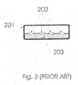
- FIG. 3 (Prior Art) Enlarged view of conventional USB male connector
- FIG. 4 (Prior Art) Conventional USB male connector without metal housing
- FIG. 5 New design of USB male connector
- FIG. 6 New design of USB male connector without housing
- FIG. 7 Plastic part of the new USB male connector with 2 sets of conductive contact pins
- the present invention converts and improves the conventional type “A” USB male connectors. These connectors are normally located on the peripheral part of the computer systems. The host computers always use type “A” USB female connectors to connect to outside world.
- peripheral devices are more demanding and produced, it is logical to modify and improve the conventional USB male connectors on the peripherals to provide these new features.
- FIG. 1 shows the conventional type “A” USB female connector located mostly on the host computer.
- the outside rectangular is a metal housing/shell ( 101 ). Inside of the metal housing/shell, there is a rectangular plastic carrier ( 103 ) that holds and supports 4 conductive contact pins ( 102 ).
- the rectangular plastic carrier ( 103 ) is like a “tongue” sticking out afloat from the rear holder.
- FIG. 2 shows a rectangular metal housing/shell ( 201 ) which is slightly smaller than the previously mentioned type “A” USB female connector housing/shell so the type “A” USB male connector housing/shell can fit and plug into the inside of type “A” USB female metal housing/shell ( 101 ).
- the inside of the conventional type “A” USB male FIG. 2 is filled half way with plastic carrier ( 203 ) and 4 conductive contact pins ( 202 ). Since the plastic part ( 203 ) of the type “A” USB male connector is half filled inside the metal housing/shell ( 201 ), it serves as a directional “key”, therefore, the type “A” USB male connector can only plug into the type “A” USB female according to the “key” position.
- the conventional type “A” USB male connector can “not” plug into the conventional type “A” USB female connector in the opposite orientation.
- FIG. 3 shows the enlarged view of conventional type “A” USB male connectors.
- the plastic part ( 203 ) is filled half way inside, to serve as directional “key” and there is no gaps between the plastic part ( 203 ) and the rectangular metal housing/shell ( 201 ) of the type “A” USB male connector.
- FIG. 4 shows the conventional type “A” USB male connector rectangular plastic piece without metal housing.
- this plastic ( 202 ) is half the size of the opening of the metal housing/shell ( 201 ), making the conventional type “A” USB male connector only plug into the female counter part the “matching” way.
- the present invention of user-friendly USB male connector is reducing the size of the rectangular plastic ( 203 ) inside the conventional type “A” USB male connector, make it much thinner (0.024′′) ( 504 ).
- the thin plastic ( 504 ) is placed and attached at the center of the conventional type “A” USB male connector housing/shell ( 201 ). As we can see FIG. 5 , the thin plastic ( 504 ) does not fill half the space as the conventional type “A” USB male connector does.
- the thinner plastic ( 504 ) is placed at the center of the conventional type “A” USB male connector housing/shell ( 201 ) and provides symmetrical and equal spacing from top to the thin plastic ( 505 ) and bottom to the thin plastic ( 506 ).
- FIG. 6 shows the “thin” rectangular piece ( 504 ) of the connector without housing. There are conductive contact pins ( 501 ) ( 502 ) on opposite sides of the piece.
- FIG. 7 shows the thin plastic piece ( 504 ) with the 4 position conductive contact pins ( 701 ) ( 702 ) on the modified thin plastic piece.
- Normal, regular insertion of the user-friendly USB male connection uses ( 701 ) conductive contact pins.
- the other 4 position conductive contact pins ( 702 ) is for opposite insertions and conductive contact pins have to be re-arranged and in reverse order for connection to the peripheral devices.
- the recommended way of implementation is to use a thin (0.024 inch), strong, low-cost double layered fiber glass (FR4) PC (Printed Circuit) board, etches the copper traces as conductive contact pins, plates it with gold on both side of the PC board, drills through holes ( 703 ), and routes the traces to mirror and reverse the arrangement of 4 wires of the user-friendly type “A” USB power lines and signals.
- FR4 Printed Circuit
- the newly modified user-friendly type “A” USB male connector is 100% physically and functionally compatible to the existing and future USB female type “A” connectors. It is a truly user-friendly operation with the spare set of conductive contact pins for users to quickly and easily plug into their peripheral devices and eliminating the possibilities of damaging both male and female USB connectors.
- USB 3.0 specifications will also be compatible with future and newly published USB 3.0 specifications.
- futuristic USB 3.0 specifications provides additional 5 more smaller conductive contact pins (on the same side) behind original 4 conductive contact pins.
Abstract
Description
| User-friendly type “A” | Conventional type | ||
| USB male connector | “A” USB male | ||
| (the invention) | connector (prior art) | ||
| Fast to plug in? | Yes | No |
| Works in opposite | Yes | No |
| position? | ||
| Spare or backup | Yes | No |
| connections? | ||
| Preventing/protecting | Yes | No |
| damage to USB | (Plug in either way . . . | (Wrong way and |
| connector? | so it won't damage the | brute force insertions |
| connectors) | will damage both | |
| USB connectors) | ||
| How about cost? | Cost less as no plastic | Cost more |
| wasted to serve as “key” | ||
| Overall performance? | Perfect | Need improve |
Claims (17)
Priority Applications (6)
| Application Number | Priority Date | Filing Date | Title |
|---|---|---|---|
| US12/492,763 US7717717B1 (en) | 2009-06-26 | 2009-06-26 | User-friendly USB connector |
| CN2009202665803U CN201623325U (en) | 2009-06-26 | 2009-11-11 | USB male interface convenient for users |
| CN200910221809.6A CN101728664B (en) | 2009-06-26 | 2009-11-11 | User-friendly usb male connector and method for designing thereof |
| JP2010000157U JP3158319U (en) | 2009-06-26 | 2010-01-13 | USB connector for easy insertion and connection |
| CA2707240A CA2707240C (en) | 2009-06-26 | 2010-06-23 | User-friendly usb connector |
| JP2013002753A JP5636620B2 (en) | 2009-06-26 | 2013-01-10 | USB connector for easy insertion and connection |
Applications Claiming Priority (1)
| Application Number | Priority Date | Filing Date | Title |
|---|---|---|---|
| US12/492,763 US7717717B1 (en) | 2009-06-26 | 2009-06-26 | User-friendly USB connector |
Publications (1)
| Publication Number | Publication Date |
|---|---|
| US7717717B1 true US7717717B1 (en) | 2010-05-18 |
Family
ID=42166534
Family Applications (1)
| Application Number | Title | Priority Date | Filing Date |
|---|---|---|---|
| US12/492,763 Active - Reinstated US7717717B1 (en) | 2009-06-26 | 2009-06-26 | User-friendly USB connector |
Country Status (4)
| Country | Link |
|---|---|
| US (1) | US7717717B1 (en) |
| JP (2) | JP3158319U (en) |
| CN (2) | CN201623325U (en) |
| CA (1) | CA2707240C (en) |
Cited By (37)
| Publication number | Priority date | Publication date | Assignee | Title |
|---|---|---|---|---|
| US20120015561A1 (en) * | 2010-07-19 | 2012-01-19 | Chou Hsien Tsai | Electrical connector |
| US20120231655A1 (en) * | 2011-03-11 | 2012-09-13 | Huang guang-li | Electrical connector |
| US20120276760A1 (en) * | 2010-01-12 | 2012-11-01 | Clear Electronics, Inc | Double-sided plug having a quadrangular frame |
| US8461465B2 (en) | 2010-05-28 | 2013-06-11 | Apple Inc. | Conductive frame for an electrical connector |
| CN103187642A (en) * | 2012-08-16 | 2013-07-03 | 赖约瑟 | Conveniently used USB (Universal Serial Bus) connector free from metal cover |
| US8517766B2 (en) | 2011-11-07 | 2013-08-27 | Apple Inc. | Plug connector with external contacts |
| US20140068933A1 (en) * | 2012-09-11 | 2014-03-13 | Apple Inc. | Connectors and methods for manufacturing connectors |
| US8686600B2 (en) | 2011-11-07 | 2014-04-01 | Apple Inc. | Techniques for configuring contacts of a connector |
| US8724281B2 (en) | 2012-04-25 | 2014-05-13 | Apple Inc. | Techniques for detecting removal of a connector |
| US8777666B2 (en) | 2012-09-07 | 2014-07-15 | Apple Inc. | Plug connector modules |
| USRE45050E1 (en) | 2007-01-05 | 2014-07-29 | Apple Inc. | Systems and methods for determining the configuration of electronic connections |
| US8799527B2 (en) | 2012-09-07 | 2014-08-05 | Apple Inc. | Data structures for facilitating communication between a host device and an accessory |
| US8882524B2 (en) | 2010-06-21 | 2014-11-11 | Apple Inc. | External contact plug connector |
| US8891216B2 (en) | 2012-04-25 | 2014-11-18 | Apple Inc. | Techniques for detecting removal of a connector |
| US8911260B2 (en) | 2010-06-21 | 2014-12-16 | Apple Inc. | External contact plug connector |
| US8931962B2 (en) | 2010-06-18 | 2015-01-13 | Apple Inc. | Dual orientation connector with side contacts |
| US9054477B2 (en) | 2012-09-11 | 2015-06-09 | Apple Inc. | Connectors and methods for manufacturing connectors |
| US9059531B2 (en) | 2012-09-11 | 2015-06-16 | Apple Inc. | Connectors and methods for manufacturing connectors |
| US20150207254A1 (en) * | 2014-01-22 | 2015-07-23 | Apple Inc. | Molded Plastic Structures With Graphene Signal Paths |
| US9093803B2 (en) | 2012-09-07 | 2015-07-28 | Apple Inc. | Plug connector |
| US9112327B2 (en) | 2011-11-30 | 2015-08-18 | Apple Inc. | Audio/video connector for an electronic device |
| US9124048B2 (en) | 2010-06-09 | 2015-09-01 | Apple Inc. | Flexible TRS connector |
| US9142925B2 (en) | 2010-05-28 | 2015-09-22 | Apple Inc. | D-shaped connector |
| US20150288110A1 (en) * | 2014-04-03 | 2015-10-08 | Hosiden Corporation | Connector |
| EP2999060A1 (en) | 2014-09-18 | 2016-03-23 | Joseph Lai | Magnetic force assisted connector adapters |
| US9307312B2 (en) | 2013-03-15 | 2016-04-05 | Apple Inc. | Audio accessory with internal clock |
| US9325097B2 (en) | 2012-11-16 | 2016-04-26 | Apple Inc. | Connector contacts with thermally conductive polymer |
| US9350125B2 (en) | 2013-01-24 | 2016-05-24 | Apple Inc. | Reversible USB connector with compliant member to spread stress and increase contact normal force |
| US9478918B1 (en) * | 2015-04-10 | 2016-10-25 | Zheng-Kai Yin | USB connector having a tongue with a plurality of contacts on its upper and lower sides symmetrically and reversely arranged |
| WO2017065769A1 (en) * | 2015-10-15 | 2017-04-20 | Hewlett-Packard Development Company, L.P. | Utilizing pins on a universal serial bus (usb) type-c connector for a data signal |
| US20170155208A1 (en) * | 2015-11-27 | 2017-06-01 | Foxconn Interconnect Technology Limited | Waterproof electrical connector |
| US20170179634A1 (en) * | 2015-12-18 | 2017-06-22 | Foxconn Interconnect Technology Limited | Connector with waterproof structure |
| US20170279226A1 (en) * | 2014-09-19 | 2017-09-28 | Chou Hsien Tsai | Reversible dual-position electric connector and method of assembling the same |
| WO2017220817A1 (en) * | 2016-06-24 | 2017-12-28 | Ceramtec Gmbh | Components for plug-in connectors |
| US20180011255A1 (en) * | 2014-12-05 | 2018-01-11 | Joseph Lai | User-Friendly USB Connectors with Fiber-Optical Connections |
| US10014638B1 (en) * | 2016-12-21 | 2018-07-03 | Microsoft Technology Licensing, Llc | Ultra-thin USB-C connector |
| USRE49451E1 (en) | 2015-10-15 | 2023-03-07 | Samsung Electronics Co., Ltd. | Electronic device case and material layer details of the same |
Families Citing this family (8)
| Publication number | Priority date | Publication date | Assignee | Title |
|---|---|---|---|---|
| US7717717B1 (en) * | 2009-06-26 | 2010-05-18 | Joseph Lai | User-friendly USB connector |
| CN102324637A (en) * | 2011-05-13 | 2012-01-18 | 陈觉明 | Electrical-connector plug and socket, double-surfaced U disk, card reader and interface converter |
| TWI459208B (en) * | 2011-11-18 | 2014-11-01 | Primax Electronics Ltd | Usb device and method for assembling usb device |
| JP2014017122A (en) * | 2012-07-09 | 2014-01-30 | Buffalo Inc | External apparatus |
| WO2015158307A1 (en) | 2014-04-17 | 2015-10-22 | 蔡周贤 | Reversible electrical connection female socket and reversible electrical connection male plug and combination thereof |
| WO2015197002A1 (en) * | 2014-06-24 | 2015-12-30 | 蔡周贤 | Electrical connector |
| KR20180030984A (en) * | 2015-07-16 | 2018-03-27 | 네스텍 소시에테아노님 | Disposable cup for heating food products |
| CN107565277B (en) * | 2017-07-31 | 2019-09-17 | 北京汽车股份有限公司 | USB maternal interface and automobile |
Citations (15)
| Publication number | Priority date | Publication date | Assignee | Title |
|---|---|---|---|---|
| US6626706B2 (en) | 2002-02-08 | 2003-09-30 | Microsoft Corporation | Eight-pin electrical connector and USB connector |
| US6893267B1 (en) | 2003-08-07 | 2005-05-17 | Wen Hsiang Yueh | USB plug with a multi-directional rotation structure |
| US6948983B1 (en) | 2004-08-10 | 2005-09-27 | Megaforce Company Limited | Slim USB male connector with anti-disorientation design |
| US6981887B1 (en) | 2004-08-26 | 2006-01-03 | Lenovo (Singapore) Pte. Ltd. | Universal fit USB connector |
| US6991483B1 (en) * | 2002-06-11 | 2006-01-31 | Henry Milan | Flash memory drive with quick connector |
| US7004794B2 (en) | 2003-09-11 | 2006-02-28 | Super Talent Electronics, Inc. | Low-profile USB connector without metal case |
| US7052287B1 (en) | 2005-05-16 | 2006-05-30 | Super Talent Electronics, Inc. | USB device with plastic housing having integrated plug shell |
| US7090541B1 (en) | 2005-05-27 | 2006-08-15 | Inventec Multimedia & Telecom Corporation | Slim USB electronic device |
| US7331796B2 (en) * | 2005-09-08 | 2008-02-19 | International Business Machines Corporation | Land grid array (LGA) interposer utilizing metal-on-elastomer hemi-torus and other multiple points of contact geometries |
| US7381060B2 (en) * | 2006-05-25 | 2008-06-03 | Lotes Co., Ltd. | Electrical connector array |
| US7507119B2 (en) * | 2000-01-06 | 2009-03-24 | Super Talent Electronics, Inc. | USB device with integrated USB plug with USB-substrate supporter inside |
| US20090111320A1 (en) * | 2007-10-30 | 2009-04-30 | Sony Ericsson Mobile Communications Ab | Enhanced universal serial bus connector |
| US20090111533A1 (en) * | 2007-10-29 | 2009-04-30 | Sony Ericsson Mobile Communications Ab | Universal serial bus connector with antenna capabilities |
| US7537471B2 (en) | 2006-11-22 | 2009-05-26 | Sandisk Il, Ltd. | Systems of reliably interconnectable reversible USB connectors |
| US7645147B2 (en) * | 2004-03-19 | 2010-01-12 | Neoconix, Inc. | Electrical connector having a flexible sheet and one or more conductive connectors |
Family Cites Families (8)
| Publication number | Priority date | Publication date | Assignee | Title |
|---|---|---|---|---|
| DE19940101A1 (en) * | 1999-08-24 | 2001-03-22 | Braun Gmbh | Multi-pin connector for low voltage devices |
| JP4898437B2 (en) * | 2003-07-28 | 2012-03-14 | サンディスク セキュア コンテンツ ソリューションズ インコーポレイテッド | Electrical connector |
| EP1784896A4 (en) * | 2004-08-02 | 2007-08-08 | Milsys Ltd | Reversible universal serial bus (usb) device and connector |
| CN201038524Y (en) * | 2006-07-11 | 2008-03-19 | 孙振宇 | Double-face universal serial bus interface |
| CN201113094Y (en) * | 2007-06-20 | 2008-09-10 | 成丹 | Two-sided inserting USB mother structure |
| CN201181784Y (en) * | 2007-09-06 | 2009-01-14 | 吴宁 | USB interface capable of two-sided insertion |
| JP2010251319A (en) * | 2009-04-15 | 2010-11-04 | Chou Hsien Tsai | Socket structure with duplex electrical connection |
| US7717717B1 (en) * | 2009-06-26 | 2010-05-18 | Joseph Lai | User-friendly USB connector |
-
2009
- 2009-06-26 US US12/492,763 patent/US7717717B1/en active Active - Reinstated
- 2009-11-11 CN CN2009202665803U patent/CN201623325U/en not_active Expired - Fee Related
- 2009-11-11 CN CN200910221809.6A patent/CN101728664B/en not_active Expired - Fee Related
-
2010
- 2010-01-13 JP JP2010000157U patent/JP3158319U/en not_active Ceased
- 2010-06-23 CA CA2707240A patent/CA2707240C/en not_active Expired - Fee Related
-
2013
- 2013-01-10 JP JP2013002753A patent/JP5636620B2/en active Active
Patent Citations (16)
| Publication number | Priority date | Publication date | Assignee | Title |
|---|---|---|---|---|
| US7507119B2 (en) * | 2000-01-06 | 2009-03-24 | Super Talent Electronics, Inc. | USB device with integrated USB plug with USB-substrate supporter inside |
| US6626706B2 (en) | 2002-02-08 | 2003-09-30 | Microsoft Corporation | Eight-pin electrical connector and USB connector |
| US6991483B1 (en) * | 2002-06-11 | 2006-01-31 | Henry Milan | Flash memory drive with quick connector |
| US6893267B1 (en) | 2003-08-07 | 2005-05-17 | Wen Hsiang Yueh | USB plug with a multi-directional rotation structure |
| US7004794B2 (en) | 2003-09-11 | 2006-02-28 | Super Talent Electronics, Inc. | Low-profile USB connector without metal case |
| US7645147B2 (en) * | 2004-03-19 | 2010-01-12 | Neoconix, Inc. | Electrical connector having a flexible sheet and one or more conductive connectors |
| US6948983B1 (en) | 2004-08-10 | 2005-09-27 | Megaforce Company Limited | Slim USB male connector with anti-disorientation design |
| US6981887B1 (en) | 2004-08-26 | 2006-01-03 | Lenovo (Singapore) Pte. Ltd. | Universal fit USB connector |
| US7052287B1 (en) | 2005-05-16 | 2006-05-30 | Super Talent Electronics, Inc. | USB device with plastic housing having integrated plug shell |
| US7090541B1 (en) | 2005-05-27 | 2006-08-15 | Inventec Multimedia & Telecom Corporation | Slim USB electronic device |
| US7331796B2 (en) * | 2005-09-08 | 2008-02-19 | International Business Machines Corporation | Land grid array (LGA) interposer utilizing metal-on-elastomer hemi-torus and other multiple points of contact geometries |
| US7467951B2 (en) * | 2005-09-08 | 2008-12-23 | International Business Machines Corporation | Land grid array (LGA) interposer utilizing metal-on-elastomer hemi torus and other multiple points of contact geometries |
| US7381060B2 (en) * | 2006-05-25 | 2008-06-03 | Lotes Co., Ltd. | Electrical connector array |
| US7537471B2 (en) | 2006-11-22 | 2009-05-26 | Sandisk Il, Ltd. | Systems of reliably interconnectable reversible USB connectors |
| US20090111533A1 (en) * | 2007-10-29 | 2009-04-30 | Sony Ericsson Mobile Communications Ab | Universal serial bus connector with antenna capabilities |
| US20090111320A1 (en) * | 2007-10-30 | 2009-04-30 | Sony Ericsson Mobile Communications Ab | Enhanced universal serial bus connector |
Cited By (71)
| Publication number | Priority date | Publication date | Assignee | Title |
|---|---|---|---|---|
| USRE45492E1 (en) | 2007-01-05 | 2015-04-28 | Apple Inc. | Systems and methods for determining the configuration of electronic connections |
| USRE45050E1 (en) | 2007-01-05 | 2014-07-29 | Apple Inc. | Systems and methods for determining the configuration of electronic connections |
| US9065231B2 (en) * | 2010-01-12 | 2015-06-23 | Clear Electronics, Inc | Reversible USB connector |
| US20120276760A1 (en) * | 2010-01-12 | 2012-11-01 | Clear Electronics, Inc | Double-sided plug having a quadrangular frame |
| US9871319B2 (en) | 2010-05-28 | 2018-01-16 | Apple Inc. | Dual orientation connector with external contacts |
| US9142925B2 (en) | 2010-05-28 | 2015-09-22 | Apple Inc. | D-shaped connector |
| US10637192B2 (en) | 2010-05-28 | 2020-04-28 | Apple Inc. | Dual orientation connector with external contacts |
| US8517751B1 (en) | 2010-05-28 | 2013-08-27 | Apple Inc. | Dual orientation connector with external contacts and conductive frame |
| US8535075B1 (en) | 2010-05-28 | 2013-09-17 | Apple Inc. | Electronic device with circuitry to detect the insertion orientation of a plug connector |
| US10090619B2 (en) * | 2010-05-28 | 2018-10-02 | Apple Inc. | Dual orientation connector with external contacts |
| US20150155657A1 (en) * | 2010-05-28 | 2015-06-04 | Apple Inc. | Dual orientation connector with external contacts |
| US20180145452A1 (en) * | 2010-05-28 | 2018-05-24 | Apple Inc. | Dual orientation connector with external contacts |
| US8461465B2 (en) | 2010-05-28 | 2013-06-11 | Apple Inc. | Conductive frame for an electrical connector |
| US9478905B2 (en) * | 2010-05-28 | 2016-10-25 | Apple Inc. | Dual orientation connector with external contacts |
| US8998632B2 (en) | 2010-05-28 | 2015-04-07 | Apple Inc. | Dual orientation connector with external contacts |
| US9124048B2 (en) | 2010-06-09 | 2015-09-01 | Apple Inc. | Flexible TRS connector |
| US8931962B2 (en) | 2010-06-18 | 2015-01-13 | Apple Inc. | Dual orientation connector with side contacts |
| US8882524B2 (en) | 2010-06-21 | 2014-11-11 | Apple Inc. | External contact plug connector |
| US8911260B2 (en) | 2010-06-21 | 2014-12-16 | Apple Inc. | External contact plug connector |
| US9142926B2 (en) * | 2010-07-19 | 2015-09-22 | Chou Hsien Tsai | Electrical connector for bidirectional plug insertion |
| US20120015561A1 (en) * | 2010-07-19 | 2012-01-19 | Chou Hsien Tsai | Electrical connector |
| US10680393B2 (en) * | 2010-07-19 | 2020-06-09 | Chou Hsien Tsai | Bidirectional duplex electrical connector having circuit board and combination of the bidirectional duplex electrical connector and docking electrical connector |
| US20150288115A1 (en) * | 2010-07-19 | 2015-10-08 | Chou Hsien Tsai | Electrical connector having step formed between connection surfaces |
| US10074947B2 (en) * | 2010-07-19 | 2018-09-11 | Chou Hsien Tsai | Electrical connector having step formed between connection surfaces for bidirectionally electrical connections |
| US8277258B1 (en) * | 2011-03-11 | 2012-10-02 | Cheng Uei Precision Industry Co., Ltd. | Electrical connector |
| US20120231655A1 (en) * | 2011-03-11 | 2012-09-13 | Huang guang-li | Electrical connector |
| US8806067B2 (en) | 2011-11-07 | 2014-08-12 | Apple Inc. | Techniques for configuring contacts of a connector |
| US8686600B2 (en) | 2011-11-07 | 2014-04-01 | Apple Inc. | Techniques for configuring contacts of a connector |
| US8517766B2 (en) | 2011-11-07 | 2013-08-27 | Apple Inc. | Plug connector with external contacts |
| US8573995B2 (en) | 2011-11-07 | 2013-11-05 | Apple Inc. | Dual orientation connector with external contacts and conductive frame |
| US8647156B2 (en) | 2011-11-07 | 2014-02-11 | Apple Inc. | Plug connector with external contacts |
| US9106031B2 (en) | 2011-11-07 | 2015-08-11 | Apple Inc. | Dual orientation electronic connector |
| US9979139B2 (en) | 2011-11-07 | 2018-05-22 | Apple Inc. | Dual orientation electronic connector |
| US9667007B2 (en) | 2011-11-07 | 2017-05-30 | Apple Inc. | Techniques for configuring contacts of a connector |
| US9647398B2 (en) | 2011-11-07 | 2017-05-09 | Apple Inc. | Dual orientation electronic connector |
| US8708745B2 (en) | 2011-11-07 | 2014-04-29 | Apple Inc. | Dual orientation electronic connector |
| US9437984B2 (en) | 2011-11-07 | 2016-09-06 | Apple Inc. | Dual orientation electronic connector |
| US9293876B2 (en) | 2011-11-07 | 2016-03-22 | Apple Inc. | Techniques for configuring contacts of a connector |
| US9112327B2 (en) | 2011-11-30 | 2015-08-18 | Apple Inc. | Audio/video connector for an electronic device |
| US8891216B2 (en) | 2012-04-25 | 2014-11-18 | Apple Inc. | Techniques for detecting removal of a connector |
| US9166345B2 (en) | 2012-04-25 | 2015-10-20 | Apple Inc. | Techniques for detecting removal of a connector |
| US8724281B2 (en) | 2012-04-25 | 2014-05-13 | Apple Inc. | Techniques for detecting removal of a connector |
| CN103187642A (en) * | 2012-08-16 | 2013-07-03 | 赖约瑟 | Conveniently used USB (Universal Serial Bus) connector free from metal cover |
| US9093803B2 (en) | 2012-09-07 | 2015-07-28 | Apple Inc. | Plug connector |
| US9223742B2 (en) | 2012-09-07 | 2015-12-29 | Apple Inc. | Data structures for facilitating communication between a host device and an accessory |
| US8777666B2 (en) | 2012-09-07 | 2014-07-15 | Apple Inc. | Plug connector modules |
| US8799527B2 (en) | 2012-09-07 | 2014-08-05 | Apple Inc. | Data structures for facilitating communication between a host device and an accessory |
| US9054477B2 (en) | 2012-09-11 | 2015-06-09 | Apple Inc. | Connectors and methods for manufacturing connectors |
| US9160129B2 (en) * | 2012-09-11 | 2015-10-13 | Apple Inc. | Connectors and methods for manufacturing connectors |
| US20140068933A1 (en) * | 2012-09-11 | 2014-03-13 | Apple Inc. | Connectors and methods for manufacturing connectors |
| US9059531B2 (en) | 2012-09-11 | 2015-06-16 | Apple Inc. | Connectors and methods for manufacturing connectors |
| US9325097B2 (en) | 2012-11-16 | 2016-04-26 | Apple Inc. | Connector contacts with thermally conductive polymer |
| US9350125B2 (en) | 2013-01-24 | 2016-05-24 | Apple Inc. | Reversible USB connector with compliant member to spread stress and increase contact normal force |
| US9307312B2 (en) | 2013-03-15 | 2016-04-05 | Apple Inc. | Audio accessory with internal clock |
| US20150207254A1 (en) * | 2014-01-22 | 2015-07-23 | Apple Inc. | Molded Plastic Structures With Graphene Signal Paths |
| US20150288110A1 (en) * | 2014-04-03 | 2015-10-08 | Hosiden Corporation | Connector |
| KR20150115632A (en) * | 2014-04-03 | 2015-10-14 | 호시덴 가부시기가이샤 | Connector |
| US9716350B2 (en) * | 2014-04-03 | 2017-07-25 | Hosiden Corporation | Connector having a thermal protection circuit |
| EP2999060A1 (en) | 2014-09-18 | 2016-03-23 | Joseph Lai | Magnetic force assisted connector adapters |
| US20170279226A1 (en) * | 2014-09-19 | 2017-09-28 | Chou Hsien Tsai | Reversible dual-position electric connector and method of assembling the same |
| US10297954B2 (en) * | 2014-09-19 | 2019-05-21 | Chou Hsien Tsai | Reversible dual-position electric connector and method of assembling the same |
| US20180011255A1 (en) * | 2014-12-05 | 2018-01-11 | Joseph Lai | User-Friendly USB Connectors with Fiber-Optical Connections |
| US9478918B1 (en) * | 2015-04-10 | 2016-10-25 | Zheng-Kai Yin | USB connector having a tongue with a plurality of contacts on its upper and lower sides symmetrically and reversely arranged |
| WO2017065769A1 (en) * | 2015-10-15 | 2017-04-20 | Hewlett-Packard Development Company, L.P. | Utilizing pins on a universal serial bus (usb) type-c connector for a data signal |
| USRE49451E1 (en) | 2015-10-15 | 2023-03-07 | Samsung Electronics Co., Ltd. | Electronic device case and material layer details of the same |
| US9871317B2 (en) * | 2015-11-27 | 2018-01-16 | Foxconn Interconnect Technology Limited | Waterproof electrical connector |
| US20170155208A1 (en) * | 2015-11-27 | 2017-06-01 | Foxconn Interconnect Technology Limited | Waterproof electrical connector |
| US9768544B2 (en) * | 2015-12-18 | 2017-09-19 | Foxconn Interconnect Technology Limited | Connector with waterproof structure |
| US20170179634A1 (en) * | 2015-12-18 | 2017-06-22 | Foxconn Interconnect Technology Limited | Connector with waterproof structure |
| WO2017220817A1 (en) * | 2016-06-24 | 2017-12-28 | Ceramtec Gmbh | Components for plug-in connectors |
| US10014638B1 (en) * | 2016-12-21 | 2018-07-03 | Microsoft Technology Licensing, Llc | Ultra-thin USB-C connector |
Also Published As
| Publication number | Publication date |
|---|---|
| JP3158319U (en) | 2010-03-25 |
| CA2707240A1 (en) | 2010-09-15 |
| CN201623325U (en) | 2010-11-03 |
| CN101728664B (en) | 2015-12-16 |
| CN101728664A (en) | 2010-06-09 |
| JP2013138009A (en) | 2013-07-11 |
| JP5636620B2 (en) | 2014-12-10 |
| CA2707240C (en) | 2011-05-24 |
Similar Documents
| Publication | Publication Date | Title |
|---|---|---|
| US7717717B1 (en) | User-friendly USB connector | |
| EP1649555B1 (en) | Electrical connector | |
| CN201956490U (en) | Universal serial bus (USB) socket with two pluggable sides and plug | |
| US8794997B2 (en) | Wall outlet type USB hub with independent charging function | |
| US7938659B1 (en) | Compound connector plug | |
| CN102214882B (en) | Electrical connector combination | |
| WO2015165416A1 (en) | Usb plug capable of being plugged in positive and negative directions | |
| TW201344396A (en) | Assembly structure of an electronic device | |
| US8746990B2 (en) | Universal modular connector | |
| CN204597047U (en) | A kind of pin connector based on TYPE-C | |
| US10439326B2 (en) | Button structure and terminal applying same | |
| US8845366B2 (en) | Apparatus, system and method for composite and symmetrical hybrid electronic connectors | |
| US20130045632A1 (en) | User-Friendly No-Metal Shell USB male Connector | |
| CN203850552U (en) | Plug connector, socket connector, and combination thereof | |
| US6896527B1 (en) | Slim USB male connector with system grounding | |
| KR101348141B1 (en) | Multi type receptacle connector and Plug connector applied for it | |
| US20140213111A1 (en) | Connector with expandable chip | |
| CN201508929U (en) | Easy-insert USB connector | |
| CN202454842U (en) | Electric connector with built-in signal gain circuit | |
| TWM445791U (en) | Universal circuit board module and connector using the universal circuit board module | |
| US8029304B1 (en) | Portable storage device | |
| TWM546033U (en) | Multi-card connector module for electronic communication device | |
| CN104538773A (en) | Power plug connector capable of being plugged in forward and reverse directions | |
| TWI633716B (en) | Multi-card connector module for communication electronic device | |
| CN202632767U (en) | Novel USB (Universal Serial Bus) storage equipment |
Legal Events
| Date | Code | Title | Description |
|---|---|---|---|
| FPAY | Fee payment |
Year of fee payment: 4 |
|
| FEPP | Fee payment procedure |
Free format text: MAINTENANCE FEE REMINDER MAILED (ORIGINAL EVENT CODE: REM.) |
|
| LAPS | Lapse for failure to pay maintenance fees |
Free format text: PATENT EXPIRED FOR FAILURE TO PAY MAINTENANCE FEES (ORIGINAL EVENT CODE: EXP.) |
|
| PRDP | Patent reinstated due to the acceptance of a late maintenance fee |
Effective date: 20180621 |
|
| FEPP | Fee payment procedure |
Free format text: SURCHARGE, PETITION TO ACCEPT PYMT AFTER EXP, UNINTENTIONAL. (ORIGINAL EVENT CODE: M2558); ENTITY STATUS OF PATENT OWNER: SMALL ENTITY Free format text: PETITION RELATED TO MAINTENANCE FEES FILED (ORIGINAL EVENT CODE: PMFP) Free format text: PETITION RELATED TO MAINTENANCE FEES GRANTED (ORIGINAL EVENT CODE: PMFG) |
|
| MAFP | Maintenance fee payment |
Free format text: PAYMENT OF MAINTENANCE FEE, 8TH YR, SMALL ENTITY (ORIGINAL EVENT CODE: M2552) Year of fee payment: 8 |
|
| STCF | Information on status: patent grant |
Free format text: PATENTED CASE |
|
| FP | Lapsed due to failure to pay maintenance fee |
Effective date: 20180518 |
|
| FEPP | Fee payment procedure |
Free format text: MAINTENANCE FEE REMINDER MAILED (ORIGINAL EVENT CODE: REM.); ENTITY STATUS OF PATENT OWNER: SMALL ENTITY |
|
| FEPP | Fee payment procedure |
Free format text: 11.5 YR SURCHARGE- LATE PMT W/IN 6 MO, SMALL ENTITY (ORIGINAL EVENT CODE: M2556); ENTITY STATUS OF PATENT OWNER: SMALL ENTITY |
|
| MAFP | Maintenance fee payment |
Free format text: PAYMENT OF MAINTENANCE FEE, 12TH YR, SMALL ENTITY (ORIGINAL EVENT CODE: M2553); ENTITY STATUS OF PATENT OWNER: SMALL ENTITY Year of fee payment: 12 |