US7717683B2 - Self contained pump electrical equipment power supply - Google Patents
Self contained pump electrical equipment power supply Download PDFInfo
- Publication number
- US7717683B2 US7717683B2 US10/142,181 US14218102A US7717683B2 US 7717683 B2 US7717683 B2 US 7717683B2 US 14218102 A US14218102 A US 14218102A US 7717683 B2 US7717683 B2 US 7717683B2
- Authority
- US
- United States
- Prior art keywords
- pump
- generator
- alternating current
- pump system
- drive shaft
- Prior art date
- Legal status (The legal status is an assumption and is not a legal conclusion. Google has not performed a legal analysis and makes no representation as to the accuracy of the status listed.)
- Expired - Fee Related, expires
Links
Images


Classifications
-
- F—MECHANICAL ENGINEERING; LIGHTING; HEATING; WEAPONS; BLASTING
- F04—POSITIVE - DISPLACEMENT MACHINES FOR LIQUIDS; PUMPS FOR LIQUIDS OR ELASTIC FLUIDS
- F04B—POSITIVE-DISPLACEMENT MACHINES FOR LIQUIDS; PUMPS
- F04B49/00—Control, e.g. of pump delivery, or pump pressure of, or safety measures for, machines, pumps, or pumping installations, not otherwise provided for, or of interest apart from, groups F04B1/00 - F04B47/00
- F04B49/06—Control using electricity
- F04B49/065—Control using electricity and making use of computers
-
- F—MECHANICAL ENGINEERING; LIGHTING; HEATING; WEAPONS; BLASTING
- F04—POSITIVE - DISPLACEMENT MACHINES FOR LIQUIDS; PUMPS FOR LIQUIDS OR ELASTIC FLUIDS
- F04B—POSITIVE-DISPLACEMENT MACHINES FOR LIQUIDS; PUMPS
- F04B23/00—Pumping installations or systems
-
- F—MECHANICAL ENGINEERING; LIGHTING; HEATING; WEAPONS; BLASTING
- F04—POSITIVE - DISPLACEMENT MACHINES FOR LIQUIDS; PUMPS FOR LIQUIDS OR ELASTIC FLUIDS
- F04D—NON-POSITIVE-DISPLACEMENT PUMPS
- F04D13/00—Pumping installations or systems
- F04D13/02—Units comprising pumps and their driving means
-
- F—MECHANICAL ENGINEERING; LIGHTING; HEATING; WEAPONS; BLASTING
- F04—POSITIVE - DISPLACEMENT MACHINES FOR LIQUIDS; PUMPS FOR LIQUIDS OR ELASTIC FLUIDS
- F04D—NON-POSITIVE-DISPLACEMENT PUMPS
- F04D15/00—Control, e.g. regulation, of pumps, pumping installations or systems
-
- H—ELECTRICITY
- H02—GENERATION; CONVERSION OR DISTRIBUTION OF ELECTRIC POWER
- H02K—DYNAMO-ELECTRIC MACHINES
- H02K7/00—Arrangements for handling mechanical energy structurally associated with dynamo-electric machines, e.g. structural association with mechanical driving motors or auxiliary dynamo-electric machines
- H02K7/14—Structural association with mechanical loads, e.g. with hand-held machine tools or fans
-
- H—ELECTRICITY
- H02—GENERATION; CONVERSION OR DISTRIBUTION OF ELECTRIC POWER
- H02K—DYNAMO-ELECTRIC MACHINES
- H02K7/00—Arrangements for handling mechanical energy structurally associated with dynamo-electric machines, e.g. structural association with mechanical driving motors or auxiliary dynamo-electric machines
- H02K7/18—Structural association of electric generators with mechanical driving motors, e.g. with turbines
- H02K7/1807—Rotary generators
- H02K7/1823—Rotary generators structurally associated with turbines or similar engines
Definitions
- This invention relates to systems and methods for supplying electrical power to equipment located near or attached to a pump, and more particularly, to a pump driven electrical current generator that powers electrical pump instrumentation and process control equipment located near or attached to the pump.
- the prior art utilizes essentially three basic techniques for supplying electrical power to equipment, such as pressure transmitters, temperature transmitters, vibration sensors, and the like, located near or attached to a pump.
- the first technique involves hard wiring directly to each piece of electrical equipment.
- the second technique involves providing the electrical equipment with internal batteries or external batteries.
- the third technique involves providing the electrical equipment with a combination of a rechargeable battery and solar panel. The solar panel powers the equipment during daylight hours and charges the battery for use during night hours.
- Hard wiring electrical power directly to the electrical equipment has the highest installation cost of the three methods mentioned above. In most facilities conduit and wiring must be purchased and installed from the power panel to where the pump is located. Battery powered electrical equipment has a lower installation cost but a higher maintenance cost in terms of checking battery condition and performing battery replacement. Battery powered electrical equipment with rechargeable batteries charged via solar panels reduces the need to check battery condition and battery replacement, but requires adequate light hours to recharge the batteries.
- An electrical power supply for powering electrical pump instrumentation and process control equipment associated with a pump having a rotating member comprising an electrical current generator driven by the rotating member of the pump.
- a pump system comprising a pump having a rotating member, electrical pump monitor and control equipment, an electrical current generator driven by the rotating member of the pump, the current generator for powering the electrical pump instrumentation and process control equipment.
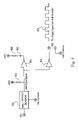
- FIG. 1 is a elevational view of an exemplary pump system that utilizes an electrical power supply made according to an embodiment of the present invention.
- FIG. 2A is perspective view of an AC generator used in the power supply of the present invention
- FIG. 2B is an elevational view of the AC generator.
- FIG. 3 is a block diagram of the electrical power supply according to the present invention.
- FIG. 4 is a circuit diagram of a voltage regulator of the electrical power supply according to an embodiment of the present invention.
- FIG. 5 is a circuit diagram of a sensor buffer of the electrical power supply according to an embodiment of the present invention.
- FIG. 1 shows a pump system 10 generally comprising a pump 12 and electrical pump instrumentation and process control equipment 30 which may be at (e.g., mechanically attached to the pump) or near the pump 12 .
- electrical pump instrumentation and process control equipment 30 which may be at (e.g., mechanically attached to the pump) or near the pump 12 .
- a similar pump system is described in detail in U.S. Pat. No. 6,464,464, entitled APPARATUS AND METHOD FOR CONTROLLING A PUMP SYSTEM, which is incorporated herein by reference in its entirety.
- the pump 12 may be of any desired type, for example, a centrifugal or positive displacement pump.
- the pump 12 has a stationary casing 14 with a pump suction inlet nozzle 16 , a discharge nozzle 18 and a bearing frame 20 with thrust end cover 22 .
- An impeller (not visible), disposed within the casing 14 , is coupled to a drive motor 24 by an impeller drive shaft 26 supported in the bearing frame 20 .
- the pump system 10 further includes a self contained electrical power supply for powering the pump instrumentation and process control equipment 30 at or near the pump 12 .
- the power supply generally comprises an alternating current (AC) generator 42 driven by the pump 12 and a voltage regulator 44 for processing the voltage output of the AC generator 42 .
- the voltage regulator 44 has DC voltage outputs for the instrumentation and process control equipment 30 .
- the DC voltage outputs of the voltage regulator may include but are not limited to +/ ⁇ 5.0 VDC, 12 VDC, and 24 VDC.
- the AC generator 42 of the power supply includes a rotating component 46 (rotor) and a stationary component 48 (stator).
- the stator 48 comprises an annular arrangement of electrically conductive wire coils or windings attached to the thrust end cover 22 of the bearing frame 20
- the rotor 46 comprises a ring-shaped permanent magnet arrangement mounted to a section of the impeller drive shaft 26 that extends through the thrust end cover 22 .
- the rotor 46 is positioned on this section of the impeller drive shaft 26 such that it spins inside the stator 48 and induces a voltage in the stator windings that alternately reverses from positive to negative polarity, thereby producing a corresponding change in the direction of current flow, i.e., an alternating current.
- the stator 48 can also be stationary mounted on the housing 25 of the drive motor 24 .
- a sensor 50 that senses impeller drive shaft rotation to provide a TTL output signal that is useful for determining pump operating parameters such as pump speed or as a trigger for vibration analysis via for example, Time Synchronous Averaging.
- the sensor 50 is typically embedded in the stator 48 such that it can sense the magnets of the rotor 46 as they pass by.
- the sensor 50 may comprise a Hall latching sensor.
- Hall latching sensor One of ordinary skill in the art will of course appreciate that other types of Hall or like sensors may be utilized.
- FIG. 3 is a block diagram of the power supply of the invention.
- Block 51 represents the permanent magnet of the AC generator
- block 52 represents a rectifier circuit that converts the AC voltage produced by the generator to an unregulated DC voltage
- block 53 represents filter capacitors that smooth the unregulated DC voltage
- block 54 represents voltage regulators that regulate the DC voltages.
- Block 55 represents the Hall effect sensor that senses impeller drive shaft rotation
- block 56 represents a buffer circuit that boosts the signal produced by the sensor to provide a square wave signal output.
- FIG. 4 shows a circuit diagram of the voltage regulator 44 according to an illustrative embodiment of the present invention.
- a bridge rectifier circuit 60 converts the AC voltage induced in the windings of the stator 48 by the rotor magnets to an unregulated DC voltage, which is smoothened by a filter capacitor 62 .
- An adjustable voltage regulator circuit 64 having an adjustable voltage regulator 66 regulates the unregulated DC voltage to a desired magnitude via a variable resistor 68 that allows the desired DC voltage at equipment output 73 to be selectively adjusted and a resistor 70 that provides the adjustable voltage regulator with feedback pertaining to its output.
- a second filter capacitor 72 smoothes the regulated DC voltage for output to the instrumentation and process control equipment.
- a fixed voltage regulator 74 whose output is smoothened via a third filter capacitor 76 , regulates the unregulated DC voltage to a predetermined DC voltage at output 77 , e.g., 5 volts DC, to power the Hall sensor 50 and a buffer circuit ( FIG. 5 ) which boosts the signal from the sensor 50 .
- FIG. 5 shows a circuit diagram of a sensor buffer according to an illustrative embodiment of the present invention, wherein the sensor 50 comprises a latching type Hall sensor.
- the regulated DC voltage produced at the sensor output 77 of the voltage regulator 74 ( FIG. 4 ) is fed to the Hall sensor 50 .
- the regulated DC voltage is also fed to first and second TTL line drivers 80 , 82 via a first resistor 84 , and an LED 86 via a second resistor 88 .
- the first TTL line driver 80 boosts the Hall output signal applied to the LED 86 , which indicates Hall operation.
- the second TTL line driver 82 boosts the Hall output signal to provide a TTL data signal 90 .
- the number of TTL cycles per revolution of the impeller shaft 26 FIG.
- 1 is dependent upon the number of poles used in the rotor 46 .
- a four pole rotor will produce a TTL data signal having 2 TTL cycles per revolution of the impeller drive shaft 26 . It should be apparent to those skilled in the art that other configurations of the generator's rotor 46 can produce more or less TTL cycles per revolution of the impeller drive shaft 26 .
- the voltage regulator and sensor buffer circuits may be formed on a conventional printed-circuit PC board using conventional electronic components.
- the PC board 95 may be mounted either integral with the AC generator or as a stand alone unit.
- the power supply of the present invention may also include a rechargeable battery backup 100 ( FIG. 1 ) for powering the pump equipment to obtain pump system information when the pump of the system is not operating.
- the rechargeable batteries 100 are recharged by the AC generator when the pump is in operation.
- the voltage regulators of block 54 are not limited to the linear voltage regulator design described above.
- a switching regulator design may be used in place of the linear voltage regulator design to produce DC voltages.
- the power supply of the present invention is an inexpensive addition to a conventional pump system, that provides local electrical power to power electrical equipment at or near the pump.
- the invention eliminates the need to hard wire electrical power directly to the instrumentation and process control equipment of the pump system from an external power grid.
- Standard batteries associated with conventional power supplies whose condition must be checked and replaced when low, are not used in the present invention. If power is required to obtain pump system information when the pump of the system is not operating, the rechargeable battery backup may be used. The dependency on adequate solar light to fully recharge the batteries is no longer needed as the rechargeable batteries are recharged when the pump is in operation.
Abstract
Description
Claims (20)
Priority Applications (3)
| Application Number | Priority Date | Filing Date | Title |
|---|---|---|---|
| US10/142,181 US7717683B2 (en) | 2002-05-09 | 2002-05-09 | Self contained pump electrical equipment power supply |
| PCT/US2003/014627 WO2003095832A1 (en) | 2002-05-09 | 2003-05-09 | Self contained pump electrical equipment power supply |
| AU2003233518A AU2003233518A1 (en) | 2002-05-09 | 2003-05-09 | Self contained pump electrical equipment power supply |
Applications Claiming Priority (1)
| Application Number | Priority Date | Filing Date | Title |
|---|---|---|---|
| US10/142,181 US7717683B2 (en) | 2002-05-09 | 2002-05-09 | Self contained pump electrical equipment power supply |
Publications (2)
| Publication Number | Publication Date |
|---|---|
| US20030210993A1 US20030210993A1 (en) | 2003-11-13 |
| US7717683B2 true US7717683B2 (en) | 2010-05-18 |
Family
ID=29399824
Family Applications (1)
| Application Number | Title | Priority Date | Filing Date |
|---|---|---|---|
| US10/142,181 Expired - Fee Related US7717683B2 (en) | 2002-05-09 | 2002-05-09 | Self contained pump electrical equipment power supply |
Country Status (3)
| Country | Link |
|---|---|
| US (1) | US7717683B2 (en) |
| AU (1) | AU2003233518A1 (en) |
| WO (1) | WO2003095832A1 (en) |
Cited By (2)
| Publication number | Priority date | Publication date | Assignee | Title |
|---|---|---|---|---|
| US20130167535A1 (en) * | 2012-01-03 | 2013-07-04 | Ronald Edward Graf | Rotary Engine with Unidirectional Monatomic Gas Flow, Static Heat Exchangers |
| WO2019054885A1 (en) * | 2017-09-14 | 2019-03-21 | Pathwalker Industries Corporation | Self-powered internal energy and power generation system and process |
Families Citing this family (6)
| Publication number | Priority date | Publication date | Assignee | Title |
|---|---|---|---|---|
| US20070216238A1 (en) * | 2006-03-16 | 2007-09-20 | Itt Industries | Self contained pump electrical equipment power supply integrated into sealing device |
| US20110068638A1 (en) * | 2007-02-26 | 2011-03-24 | Phillip Cooper | Magnetic Power Supply Engine |
| US20110056444A1 (en) * | 2009-09-08 | 2011-03-10 | Im Chai S | Polarity sequenced electro magnetic head gasket engine and replacement kit |
| US8531048B2 (en) * | 2010-11-19 | 2013-09-10 | Gulfstream, Inc. | Light kit in combination with a pump system |
| JP6013302B2 (en) * | 2013-10-04 | 2016-10-25 | 東京エレクトロン株式会社 | Bubble removal method, bubble removal apparatus, deaeration apparatus, and computer-readable recording medium |
| CA2956946A1 (en) | 2016-08-09 | 2018-02-09 | Mihn S. Tran | Foot spa with illumination |
Citations (24)
| Publication number | Priority date | Publication date | Assignee | Title |
|---|---|---|---|---|
| US1672191A (en) * | 1926-10-18 | 1928-06-05 | Gen Motors Corp | Water pump and generator mounting |
| US2364013A (en) * | 1941-07-07 | 1944-11-28 | Waseige Charles Raymond | Engined compressor-generator unit |
| US3751192A (en) * | 1971-04-12 | 1973-08-07 | Borg Warner | Submersible pump drive system |
| US4095922A (en) * | 1976-10-20 | 1978-06-20 | Tecumseh Products Company | Electro-mechanical device |
| US4429242A (en) * | 1981-06-06 | 1984-01-31 | Layh Hans Dieter | Arrangement of actual value indicator |
| US4467657A (en) * | 1982-01-20 | 1984-08-28 | Telfa Jabsco Ab | Device for measuring the amount of flow and/or the speed of flow of a medium |
| US4469966A (en) | 1981-10-28 | 1984-09-04 | Mitsubishi Denki Kabushiki Kaisha | Electric generator for use with vehicles |
| US4512726A (en) * | 1982-02-09 | 1985-04-23 | Strimling Walter E | Pump adaptable for use as an artificial heart |
| US4971522A (en) * | 1989-05-11 | 1990-11-20 | Butlin Duncan M | Control system and method for AC motor driven cyclic load |
| US5059097A (en) * | 1989-01-26 | 1991-10-22 | Diesel Kiki Co. Ltd. | Variable capacity wobble plate compressor |
| US5087824A (en) * | 1990-04-09 | 1992-02-11 | Bill Nelson | Power plant for generation of electrical power and pneumatic pressure |
| US5242278A (en) * | 1991-10-11 | 1993-09-07 | Vanair Manufacturing, Inc. | Power generator air compressor |
| US5362207A (en) * | 1993-06-09 | 1994-11-08 | Ingersoll-Rand Company | Portable diesel-driven centrifugal air compressor |
| US5604412A (en) * | 1993-03-19 | 1997-02-18 | Nidec Corporation | Brushless motor and a control circuit thereof |
| US5625276A (en) | 1994-09-14 | 1997-04-29 | Coleman Powermate, Inc. | Controller for permanent magnet generator |
| US5709103A (en) * | 1996-08-15 | 1998-01-20 | Mcdonnell Douglas Coporation | Electrically powered differential air-cycle air conditioning machine |
| US5959385A (en) * | 1995-10-19 | 1999-09-28 | Denso Corporation | Rotary machine having starter for vehicle |
| US6093986A (en) * | 1999-03-08 | 2000-07-25 | Emerson Electric Co. | Method and apparatus for powering shaft-mounted sensors on motors and generators |
| US6099265A (en) * | 1998-09-14 | 2000-08-08 | Ingersoll-Rand Company | Machine with at least two modes of operation and switching means for changing the machine mode of operation |
| US6132186A (en) * | 1997-08-06 | 2000-10-17 | Shurflo Pump Manufacturing Co. | Impeller pump driven by a dynamo electric machine having a stator comprised of a mass of metal particles |
| US6315524B1 (en) * | 1999-03-22 | 2001-11-13 | David Muhs | Pump system with vacuum source |
| US20020089248A1 (en) * | 2000-11-30 | 2002-07-11 | Gozdawa Richard Julius | Gas turbomachinery generator |
| US20030011259A1 (en) * | 2001-07-16 | 2003-01-16 | Johnsen Tyrone A. | High-speed, high-power rotary electrodynamic machine with dual rotors |
| US6534958B1 (en) * | 1999-08-16 | 2003-03-18 | Coleman Powermate, Inc. | System that supplies electrical power and compressed air with throttle control |
-
2002
- 2002-05-09 US US10/142,181 patent/US7717683B2/en not_active Expired - Fee Related
-
2003
- 2003-05-09 WO PCT/US2003/014627 patent/WO2003095832A1/en not_active Application Discontinuation
- 2003-05-09 AU AU2003233518A patent/AU2003233518A1/en not_active Abandoned
Patent Citations (26)
| Publication number | Priority date | Publication date | Assignee | Title |
|---|---|---|---|---|
| US1672191A (en) * | 1926-10-18 | 1928-06-05 | Gen Motors Corp | Water pump and generator mounting |
| US2364013A (en) * | 1941-07-07 | 1944-11-28 | Waseige Charles Raymond | Engined compressor-generator unit |
| US3751192A (en) * | 1971-04-12 | 1973-08-07 | Borg Warner | Submersible pump drive system |
| US4095922A (en) * | 1976-10-20 | 1978-06-20 | Tecumseh Products Company | Electro-mechanical device |
| US4203710A (en) * | 1976-10-20 | 1980-05-20 | Tecumseh Products Company | Unified pump and generator arrangement |
| USRE31947E (en) * | 1976-10-20 | 1985-07-16 | Tecumseh Products Company | Electro-mechanical device |
| US4429242A (en) * | 1981-06-06 | 1984-01-31 | Layh Hans Dieter | Arrangement of actual value indicator |
| US4469966A (en) | 1981-10-28 | 1984-09-04 | Mitsubishi Denki Kabushiki Kaisha | Electric generator for use with vehicles |
| US4467657A (en) * | 1982-01-20 | 1984-08-28 | Telfa Jabsco Ab | Device for measuring the amount of flow and/or the speed of flow of a medium |
| US4512726A (en) * | 1982-02-09 | 1985-04-23 | Strimling Walter E | Pump adaptable for use as an artificial heart |
| US5059097A (en) * | 1989-01-26 | 1991-10-22 | Diesel Kiki Co. Ltd. | Variable capacity wobble plate compressor |
| US4971522A (en) * | 1989-05-11 | 1990-11-20 | Butlin Duncan M | Control system and method for AC motor driven cyclic load |
| US5087824A (en) * | 1990-04-09 | 1992-02-11 | Bill Nelson | Power plant for generation of electrical power and pneumatic pressure |
| US5242278A (en) * | 1991-10-11 | 1993-09-07 | Vanair Manufacturing, Inc. | Power generator air compressor |
| US5604412A (en) * | 1993-03-19 | 1997-02-18 | Nidec Corporation | Brushless motor and a control circuit thereof |
| US5362207A (en) * | 1993-06-09 | 1994-11-08 | Ingersoll-Rand Company | Portable diesel-driven centrifugal air compressor |
| US5625276A (en) | 1994-09-14 | 1997-04-29 | Coleman Powermate, Inc. | Controller for permanent magnet generator |
| US5959385A (en) * | 1995-10-19 | 1999-09-28 | Denso Corporation | Rotary machine having starter for vehicle |
| US5709103A (en) * | 1996-08-15 | 1998-01-20 | Mcdonnell Douglas Coporation | Electrically powered differential air-cycle air conditioning machine |
| US6132186A (en) * | 1997-08-06 | 2000-10-17 | Shurflo Pump Manufacturing Co. | Impeller pump driven by a dynamo electric machine having a stator comprised of a mass of metal particles |
| US6099265A (en) * | 1998-09-14 | 2000-08-08 | Ingersoll-Rand Company | Machine with at least two modes of operation and switching means for changing the machine mode of operation |
| US6093986A (en) * | 1999-03-08 | 2000-07-25 | Emerson Electric Co. | Method and apparatus for powering shaft-mounted sensors on motors and generators |
| US6315524B1 (en) * | 1999-03-22 | 2001-11-13 | David Muhs | Pump system with vacuum source |
| US6534958B1 (en) * | 1999-08-16 | 2003-03-18 | Coleman Powermate, Inc. | System that supplies electrical power and compressed air with throttle control |
| US20020089248A1 (en) * | 2000-11-30 | 2002-07-11 | Gozdawa Richard Julius | Gas turbomachinery generator |
| US20030011259A1 (en) * | 2001-07-16 | 2003-01-16 | Johnsen Tyrone A. | High-speed, high-power rotary electrodynamic machine with dual rotors |
Cited By (2)
| Publication number | Priority date | Publication date | Assignee | Title |
|---|---|---|---|---|
| US20130167535A1 (en) * | 2012-01-03 | 2013-07-04 | Ronald Edward Graf | Rotary Engine with Unidirectional Monatomic Gas Flow, Static Heat Exchangers |
| WO2019054885A1 (en) * | 2017-09-14 | 2019-03-21 | Pathwalker Industries Corporation | Self-powered internal energy and power generation system and process |
Also Published As
| Publication number | Publication date |
|---|---|
| WO2003095832A1 (en) | 2003-11-20 |
| AU2003233518A1 (en) | 2003-11-11 |
| US20030210993A1 (en) | 2003-11-13 |
Similar Documents
| Publication | Publication Date | Title |
|---|---|---|
| CN101233326B (en) | Blower and electric device with such blower mounted thereon | |
| EP1562281B1 (en) | Wind power generator | |
| US6278248B1 (en) | Brushless DC motor fan driven by an AC power source | |
| US5336956A (en) | Brushless dynamo machine with novel armature construction | |
| JP4173587B2 (en) | Air conditioning control device for brushless motor | |
| EP2159582B1 (en) | Methods and Apparatus for Monitoring Average Current and Input Power in an Electronically Commutated Motor | |
| EP1968185B1 (en) | Methods and systems for operating direct current motors | |
| US6236183B1 (en) | Device for sensing the angular position for controlling a synchronous motor excited by a permanent magnet | |
| KR100904128B1 (en) | Method and Apparatus for Driving a Brushless DC Motor | |
| US7717683B2 (en) | Self contained pump electrical equipment power supply | |
| US7262568B2 (en) | Brushless DC motor coupled directly to AC source and electric apparatus using the same motor | |
| US20100164420A1 (en) | Brushless direct current motor and driving unit thereof | |
| US20140339943A1 (en) | Energy harvester and rotating shaft vibration sensor | |
| EP1998434A2 (en) | Drive control circuit for electric motor and elctric motor equipped with same | |
| US8093860B2 (en) | Ceiling fan motor with generator winding | |
| JP2017147817A (en) | Motor drive device | |
| CN109072853B (en) | Method and system for controlling an integrated starter-generator | |
| CN212412822U (en) | Self-charging device of gear box remote state monitoring system | |
| JPH1164545A (en) | Continuously rotating small motor control method | |
| US11770082B2 (en) | Electric motor for viscous pumping | |
| US6323619B1 (en) | Condition monitoring and battery recharging system | |
| CN111641248A (en) | Self-charging device of gear box remote state monitoring system | |
| JP2656890B2 (en) | Control device for canned motor pump | |
| US20110279111A1 (en) | Electronic probe housing and electronic governor for steam turbine | |
| US7609010B2 (en) | Inverter |
Legal Events
| Date | Code | Title | Description |
|---|---|---|---|
| AS | Assignment |
Owner name: ITT MANUFACTURING ENTERPRISES, INC., DELAWARE Free format text: ASSIGNMENT OF ASSIGNORS INTEREST;ASSIGNORS:SABINI, EUGENE P.;LORENC, JEROME A.;HENYAN, OAKLEY;AND OTHERS;REEL/FRAME:012886/0878 Effective date: 20020502 Owner name: ITT MANUFACTURING ENTERPRISES, INC.,DELAWARE Free format text: ASSIGNMENT OF ASSIGNORS INTEREST;ASSIGNORS:SABINI, EUGENE P.;LORENC, JEROME A.;HENYAN, OAKLEY;AND OTHERS;REEL/FRAME:012886/0878 Effective date: 20020502 |
|
| STCF | Information on status: patent grant |
Free format text: PATENTED CASE |
|
| AS | Assignment |
Owner name: ITT MANUFACTURING ENTERPRISES LLC, DELAWARE Free format text: CHANGE OF NAME;ASSIGNOR:ITT MANUFACTURING ENTERPRISES, INC.;REEL/FRAME:028661/0032 Effective date: 20110930 |
|
| FPAY | Fee payment |
Year of fee payment: 4 |
|
| MAFP | Maintenance fee payment |
Free format text: PAYMENT OF MAINTENANCE FEE, 8TH YEAR, LARGE ENTITY (ORIGINAL EVENT CODE: M1552) Year of fee payment: 8 |
|
| FEPP | Fee payment procedure |
Free format text: MAINTENANCE FEE REMINDER MAILED (ORIGINAL EVENT CODE: REM.); ENTITY STATUS OF PATENT OWNER: LARGE ENTITY |
|
| LAPS | Lapse for failure to pay maintenance fees |
Free format text: PATENT EXPIRED FOR FAILURE TO PAY MAINTENANCE FEES (ORIGINAL EVENT CODE: EXP.); ENTITY STATUS OF PATENT OWNER: LARGE ENTITY |
|
| STCH | Information on status: patent discontinuation |
Free format text: PATENT EXPIRED DUE TO NONPAYMENT OF MAINTENANCE FEES UNDER 37 CFR 1.362 |
|
| FP | Lapsed due to failure to pay maintenance fee |
Effective date: 20220518 |