US7701658B2 - Vehicle system and method for preparing an in-vehicle device - Google Patents
Vehicle system and method for preparing an in-vehicle device Download PDFInfo
- Publication number
- US7701658B2 US7701658B2 US11/693,133 US69313307A US7701658B2 US 7701658 B2 US7701658 B2 US 7701658B2 US 69313307 A US69313307 A US 69313307A US 7701658 B2 US7701658 B2 US 7701658B2
- Authority
- US
- United States
- Prior art keywords
- vehicle
- message
- messages
- data
- bus
- Prior art date
- Legal status (The legal status is an assumption and is not a legal conclusion. Google has not performed a legal analysis and makes no representation as to the accuracy of the status listed.)
- Expired - Fee Related, expires
Links
Images


Classifications
-
- G—PHYSICS
- G08—SIGNALLING
- G08G—TRAFFIC CONTROL SYSTEMS
- G08G1/00—Traffic control systems for road vehicles
- G08G1/20—Monitoring the location of vehicles belonging to a group, e.g. fleet of vehicles, countable or determined number of vehicles
- G08G1/205—Indicating the location of the monitored vehicles as destination, e.g. accidents, stolen, rental
Definitions
- the present disclosure relates generally to a vehicle system and a method for preparing an in-vehicle device.
- Portable electronic equipment is often provided with “locking” devices that lock certain internal components, such as hard drives, in the event that the equipment is dropped.
- the internal component when locked, is placed in a state in which data on the device and the mechanism of the component may be more likely to survive the dropping event.
- a sensor within the internal component may be used to trigger the locked state.
- a method for preparing an in-vehicle device includes monitoring a communication bus for one or more messages. The method also includes determining if at least one of the one or more messages corresponds with a message in a list of messages indicative of a change in vehicle state. Data is extracted from the at least one message that corresponds with the message in the list of messages. A signal is transmitted to the in-vehicle device based on the extracted data.
- a vehicle system includes a first unit for sensing and processing data indicative of a vehicle state, a communication bus that is coupled to the first unit, and a second unit that is coupled to the communication bus.
- the second unit includes a device with a park mode and an operating mode. The second unit activates the park mode in response to a signal received from the first unit indicating that the vehicle state has changed.
- FIG. 1 is a flowchart depicting an embodiment of a method of preparing an in-vehicle device
- FIG. 2 is a schematic diagram depicting an embodiment of a vehicle system for preparing an in-vehicle device
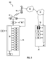
- FIG. 3 is a schematic diagram depicting an embodiment of a system including the system shown in FIG. 2 , an in-vehicle telematics unit, a wireless communication system, and a call center.
- Embodiment(s) of the method and system disclosed herein advantageously prepare in-vehicle devices when changes in vehicle behavior are detected.
- the method and system utilize different vehicle components to monitor and detect actual or potential changes in vehicle behavior.
- the in-vehicle device(s) are put into park, stop, or off mode. It is believed that parking or stopping the device prepares the device and may reduce the likelihood of damage to the device when the vehicle behavior changes substantially.
- a user may include a service subscriber and/or a vehicle operator/passenger.
- connection and/or the like are broadly defined herein to encompass a variety of divergent connected arrangements and assembly techniques. These arrangements and techniques include, but are not limited to (1) the direct communication between one component and another component with no intervening components therebetween; and (2) the communication of one component and another component with one or more components therebetween, provided that the one component being “connected to” the other component is somehow in operative communication with the other component (notwithstanding the presence of one or more additional components therebetween). Additionally, two components may be permanently, semi-permanently, or releasably engaged with and/or connected to one another.
- communication is to be construed to include all forms of communication, including direct communication and indirect communication.
- indirect communication is to be interpreted to include communication between two components having additional component(s) located therebetween.
- the method includes monitoring a communication bus for one or more messages, as shown at reference numeral 11 ; determining if at least one of the one or more messages corresponds with a message in a list of messages indicative of a change in a vehicle state, as shown at reference numeral 13 ; extracting data from the at least one message that corresponds with the message in the list of messages, as shown at reference numeral 15 ; and transmitting a signal to the in-vehicle device based on the extracted data, as shown at reference numeral 17 . It is to be understood that embodiments of the method will be discussed in further detail in reference to FIGS. 2 and 3 .
- the system 10 includes a first unit 12 , a communication bus 14 , and a second unit 16 . It is to be understood that the components of the system 10 are located within or on the vehicle 18 , shown in FIG. 3 .
- the first unit 12 senses and processes data indicative of a vehicle state.
- the first unit 12 includes sensor(s) 20 that are located within the vehicle 18 or on the exterior of the vehicle 18 .
- the sensor(s) 20 sense one or more conditions of the vehicle 18 (i.e., vehicle state). Such conditions may include vehicle speed, acceleration, and/or deceleration, wheel slip, brake application, engine torque, steering wheel angle, rollover status, chassis status, and/or the like, and/or combinations thereof.
- Non-limiting examples of such sensors 20 include vehicle collision sensors, vehicle pre-collision sensors, accelerometers, inclinometers, gyroscopes (e.g., turn rate sensors), magnetic compasses, and/or the like, and/or combinations thereof.
- the sensor(s) 20 Upon sensing the condition or vehicle state, the sensor(s) 20 generate data indicative of the condition.
- the first unit 12 also includes one or more sensor modules 22 .
- Each sensor(s) 20 is operatively connected to a sensor module 22 .
- multiple sensors 20 may be operatively connected to one sensor module 22 .
- one sensor 20 may be operatively connected to one sensor module 22 .
- any number of sensor modules 22 may be used in the system 10 .
- Non-limiting examples of sensor modules 22 include an ABS braking system module, a collision notification (CN) module, and/or other like vehicle modules, and/or combinations thereof.
- the module(s) 22 receives sensed data from the respective sensor(s) 20 operatively connected thereto.
- the module(s) 22 then process the received data and formulate one or more messages based on such data. As such, the formulated messages are indicative of the sensed vehicle state/condition.
- the first unit 12 is operatively connected to or in communication with the communication bus 14 . More specifically, the module(s) 22 of the first unit 12 are in direct communication with the system bus 24 of the communication bus 14 .
- the communication bus 14 includes the system bus 24 and an audio bus 26 . The messages formulated by the module(s) 22 are passed from the respective modules 20 to the system bus 24 , and if present, to the audio bus 26 .
- the system 10 also includes the second unit 16 , which is operatively connected or coupled to the communication bus 14 , via the system bus 24 or the audio bus 26 . It is to be understood, as shown in FIG. 2 , that the second unit 16 may be directly connected to the system bus 24 , or may be connected to the system bus 24 via, for example, the audio bus 26 .
- the second unit 16 includes the in-vehicle device 28 and a bus message listener 30 .
- the in-vehicle device 28 is switchable between a park/stop/off mode and an operating/on mode.
- the in-vehicle device 28 is a vehicle multimedia system, a vehicle audio system, and/or combinations thereof.
- the device 28 may include a hard drive 32 , a motor, a laser mechanism, a media read head mechanism, or other parts that operate the device 28 .
- the bus message listener 30 monitors the communication bus 14 for the message(s) sent from the first unit 12 .
- the bus message listener 30 scans the message(s) for content that indicates a change or an impending change in the vehicle state/condition.
- two messages of interest to the bus message listener 28 may include input or data of a braking condition that indicates a potentially abrupt stop of the vehicle, or input or data indicating an actual vehicle collision.
- the messages of interest to the bus message listener 30 may also include those messages that contain wheel slip data (e.g., front and/or rear wheel slip), brake application status (e.g., antilock brake system indication on, actual vehicle acceleration), engine torque status (e.g., accelerator effective position, accelerator effective position validity), steering wheel angle (e.g., vehicle dynamics yaw rate), rollover status (e.g., rollover sensor fault status, rollover event classification type), chassis status (e.g., brake pedal driver applied pressure detected, vehicle stability enhancement lateral acceleration), or the like, or combinations thereof.
- wheel slip data e.g., front and/or rear wheel slip
- brake application status e.g., antilock brake system indication on, actual vehicle acceleration
- engine torque status e.g., accelerator effective position, accelerator effective position validity
- steering wheel angle e.g., vehicle dynamics yaw rate
- rollover status e.g., rollover sensor fault status, rollover event classification type
- chassis status e.g., brake pedal driver applied pressure
- the bus message listener 30 stores a list of messages to monitor.
- the list of messages generally contains the type of message content for which the bus message listener 30 is listening or monitoring.
- Such a list may be delivered to the bus message listener 30 from the telematics unit (shown as reference numeral 34 in FIG. 3 ). Further, such a list may be compiled at and updated by the call center 36 , which is in operative communication with the telematics unit 34 , described further hereinbelow.
- the call center 36 sends the list to the telematics unit 34 , which transmits the list to the bus message listener 30 .
- the bus message listener 30 monitors the messages received by the communication bus 14 from the first unit 12 to determine if at least one of the messages corresponds with a message in the list of messages stored therein.
- the bus message listener 30 monitors the communication bus 14 substantially continuously or at predetermined intervals.
- Substantially continuous monitoring generally means that the bus message listener 30 monitors the communication bus 14 in near real time as soon as the vehicle 18 is turned on until the vehicle 18 is turned off. An interrupt in the substantially continuous monitoring is generated if a message of interest is detected.
- the bus message listener 30 compares the content of the messages received by the communication bus 14 with the content of the messages stored in the list. If the content of one or more of the monitored messages is found to match a message in the list, then the listener 30 extracts and examines the data from the monitored message.
- the received message may be encoded in a binary string and compared to a binary string representing the message stored in the list. If the strings match, then the bus message listener 30 extracts the data from the received message.
- the bus message listener 30 responsive to an incoming message that matches a message in the list, generates an interrupt that is recognized and acted upon by device 28 .
- the data is indicative of a sensed vehicle state/condition.
- the bus message listener 30 determines whether the vehicle state/condition has changed. Generally, the bus message listener 30 is looking for substantially rapid changes in vehicle behavior that indicate impending or actual incidences potentially likely to cause damage to the vehicle 18 and/or to the device 28 (e.g., hitting a pothole).
- the state/condition changes that the bus message listener 30 is looking for are those that indicate that the state/condition has exceeded a predetermined threshold or is outside a predetermined range.
- the predetermined threshold or range is particular to a vehicle state/condition and represents states/conditions at which the device 28 is able to activate the operating/on mode substantially without sustaining damage thereto.
- the predetermined threshold for brake application status may be when the antilock braking system is engaged.
- a significant change in brake or throttle condition within a certain amount of time may be outside a predetermined range of suitable brake or throttle condition changes.
- the bus message listener 30 transmits a signal to the device 28 to activate the park/stop/off mode.
- the signal is received by the device 28 , which, in response, activates the park/stop/off mode.
- activating the park/stop/off mode includes the in-vehicle device 28 parking a hard drive head, stopping a hard drive platter, stopping a compact disc player motor, stopping a digital video disc player motor, stopping a compact disc player laser mechanism, stopping a digital video disc player laser mechanism, stopping a blue-violet laser optical storage disk (e.g., BLU-RAY®) motor and/or laser mechanism, stopping a high-definition digital video disk player motor and/or laser mechanism, and/or the like, and/or combinations thereof. It is believed that by activating the park/stop/off mode when such vehicle changes are detected, the system 10 may substantially reduce the risk of damaging the device 28 components.
- BLU-RAY® blue-violet laser optical storage disk
- the communication system 100 includes the vehicle 18 , the vehicle system 10 , a vehicle communications network 38 , the telematics unit 34 , a wireless communication system (including, but not limited to, one or more wireless carrier systems 40 , one or more communication networks 42 , one or more land networks 44 ), and one or more call centers 36 .
- the wireless communication system is a two-way radio frequency communication system.
- vehicle 18 is a mobile vehicle with suitable hardware and software for transmitting and receiving voice and data communications.
- System 100 may include additional components suitable for use in telematics units 34 .
- vehicle communications network 38 the vehicle 18 sends signals from the telematics unit 34 to various units of equipment and systems 38 within the vehicle 18 to perform various functions, such as unlocking a door, executing personal comfort settings, and/or the like.
- vehicle communications network 46 utilizes interfaces such as controller area network (CAN), ISO standard 11989 for high speed applications, ISO standard 11519 for lower speed applications, and Society of Automotive Engineers (SAE) standard J1850 for high speed and lower speed applications.
- CAN controller area network
- SAE Society of Automotive Engineers
- the telematics unit 34 may send and receive radio transmissions from wireless carrier system 40 .
- wireless carrier system 40 may be a cellular telephone system and/or any other suitable system for transmitting signals between the vehicle 18 and communications network 42 .
- the wireless carrier system 40 may include a cellular communication transceiver, a satellite communications transceiver, a wireless computer network transceiver (a non-limiting example of which includes a Wide Area Network (WAN) transceiver), and/or combinations thereof.
- WAN Wide Area Network
- Telematics unit 34 may include a processor 48 operatively coupled to a wireless modem 50 , a location detection system 52 (a non-limiting example of which is a global positioning system (GPS)), an in-vehicle memory 54 , a microphone 56 , one or more speakers 58 , an embedded or in-vehicle mobile phone 60 , a real-time clock (RTC) 62 , a short-range wireless communication network 64 (e.g. a BLUETOOTH® unit), a user interface 66 , and/or a user interface panel 68 .
- GPS global positioning system
- RTC real-time clock
- the telematics unit 34 is operatively connected to the bus message listener 30 of the system 10 for transmitting the message list and other communications to the system 10 . It is to be understood that the bus message system 30 is also capable of transmitting signals to the telematics unit 34 , and thus to the call center 36 .
- telematics unit 34 may include additional components and functionality as desired for a particular end use. It is to be understood that the telematics unit 34 may also be implemented without one or more of the above listed components, such as, for example, speakers 58 . Additionally, it is to be understood that the speaker(s) 58 may be a component of the device 28 (for example, when the device 28 is a multimedia and/or audio system).
- the device 28 may be configured, in addition to accepting and outputting radio broadcasts, to accept and output audio and other signals.
- the device 28 may be adapted to output audio signals (i.e., an audio output) embodied in one or more of a variety of formats.
- the device 28 may output audio signals from the telematics unit 34 , FM radio, AM radio, satellite radio, a compact disc (CD), a digital audio file (such as, for example, an .mp3 file), a cassette tape, a minidisk, and/or combinations thereof.
- Processor 48 may be a micro controller, a controller, a microprocessor, a host processor, and/or a vehicle communications processor. In another embodiment, processor 48 may be an application specific integrated circuit (ASIC). Alternatively, processor 48 may be a processor working in conjunction with a central processing unit (CPU) performing the function of a general-purpose processor.
- CPU central processing unit
- Non-limiting examples of the location detection system 52 associated with processor 48 include a Global Position Satellite receiver, a radio triangulation system, a dead reckoning position system, and/or combinations thereof.
- a GPS receiver provides accurate time and latitude and longitude coordinates of the vehicle 18 responsive to a GPS broadcast signal received from a GPS satellite constellation (not shown).
- In-vehicle mobile phone 60 may be a cellular type phone, such as, for example an analog, digital, dual-mode, dual-band, multi-mode and/or multi-band cellular phone.
- RTC real time clock
- processor 48 Also associated with processor 48 is the previously mentioned real time clock (RTC) 62 , which provides accurate date and time information to the telematics unit hardware and software components that may require date and time information.
- date and time information may be requested from the RTC 62 by other telematics unit components.
- the RTC 62 may provide date and time information periodically, such as, for example, every ten milliseconds.
- Processor 48 may execute various computer programs that interact with operational modes of electronic and mechanical systems within the vehicle 34 . It is to be understood that processor 48 controls communication (e.g., call signals) between system 10 , telematics unit 34 , wireless carrier system 40 , and call center 36 .
- communication e.g., call signals
- processor 48 may generate and accept digital signals transmitted between the telematics unit 34 and the vehicle communication network 38 , which is connected to various electronic modules in the vehicle 18 . In one embodiment, these digital signals activate the programming mode and operation modes within the electronic modules, as well as provide for data transfer between the electronic modules. In another embodiment, certain signals from processor 48 may be translated into vibrations and/or visual alarms.
- software 70 may be associated with processor 48 for monitoring and/or recording the incoming caller utterances and/or data transmissions.
- the communications network 42 may include services from one or more mobile telephone switching offices and/or wireless networks. Communications network 42 connects wireless carrier system 40 to land network 44 . Communications network 42 may be any suitable system or collection of systems for connecting the wireless carrier system 40 to the vehicle 18 and the land network 44 .
- the land network 44 connects the communications network 40 to the call center 46 .
- land network 44 is a public switched telephone network (PSTN).
- land network 44 is an Internet Protocol (IP) network.
- IP Internet Protocol
- land network 44 is a wired network, an optical network, a fiber network, another wireless network, and/or any combinations thereof.
- the land network 44 may be connected to one or more landline telephones. It is to be understood that the communications network 42 and the land network 44 connect the wireless carrier system 40 to the call center 46 .
- Call center 46 may contain one or more data switches 72 , one or more communication services managers 74 , one or more communication services databases 76 containing, for example, subscriber profile records and/or subscriber information, one or more communication services advisors 78 , and one or more network systems 80 .
- a service provider may be located at the call center 36
- the call center 36 is a separate and distinct entity from the service provider.
- the service provider is located remote from the call center 36 .
- a service provider provides the user with telephone and/or Internet services.
- the service provider is a wireless carrier (such as, for example, Verizon Wireless®, Cingular®, Sprint®, etc.). It is to be understood that the service provider may interact with the call center 36 to provide service(s) to the user.
- Switch 72 of call center 36 may connect to land network 44 .
- Switch 72 may transmit voice or data transmissions from call center 36 , and may receive voice or data transmissions from telematics unit 34 in vehicle 18 through wireless carrier system 40 , communications network 42 , and land network 44 .
- a connection between the telematics unit 34 and the call center 36 may be established via the wireless carrier system 40 , communications network 42 , and/or land network 44 .
- Switch 72 may receive data transmissions from, or send data transmissions to one or more communication service managers 74 , via one or more network systems 80 .
- Call center 36 may contain one or more service advisors 78 .
- the service advisor 78 is human.
- a service advisor 78 is an automaton. It is to be understood that the service advisor 78 may be located at the call center 36 or may be located remote from the call center 36 while communicating therethrough.
- Communication may be accomplished via voice mode or data mode.
- Voice mode communications generally occur between the user and the service advisor 78 or some other third party.
- Data mode communications generally occur between the telematics unit 34 and components of the call center 36 or service provider. Data mode is used, for example, to send the list of messages from the call center 36 to the telematics unit 34 .
- the communication is established via a connection extending (e.g., via the wireless communication system) between the telematics unit 34 and the call center 36 .
- verbal communication may take place via microphone 56 coupled to the in-vehicle or mobile phone 60 associated with the telematics unit 34 .
- caller utterances into the microphone 56 are received at the call center 36 , which may tokenize the utterance stream for further processing.
- the tokenized utterances are placed in a subscriber information database 76 at the call center 36 .
- Communication between a telematics unit 34 user and a service advisor 78 may be initiated automatically, or may be initiated by the user or the service advisor 78 .
- the call center 36 initiates communication with the telematics unit 34 in data mode to transmit data to and/or receive data from the telematics unit 34 .
- the user may initiate a call or a request via an input system (e.g., user interface 66 and/or user interface panel 68 ) in communication with the telematics unit 34 and/or the two-way radio frequency communication system. Initiation of the communication may be verbal and/or via a physical motion.
- the input system may include an alphanumeric keypad, a microphone 56 , a menu selection system, and/or combinations thereof.
- embodiment(s) of the method and systems 10 , 100 disclosed herein advantageously prepare in-vehicle devices 28 when changes in one or more vehicle states/conditions are detected. When such changes are recognized, the in-vehicle device(s) 28 are activated in park, stop, or off mode, thereby reducing the likelihood of damage to the device 28 during such radical changes.
Abstract
Description
Claims (19)
Priority Applications (1)
| Application Number | Priority Date | Filing Date | Title |
|---|---|---|---|
| US11/693,133 US7701658B2 (en) | 2007-03-29 | 2007-03-29 | Vehicle system and method for preparing an in-vehicle device |
Applications Claiming Priority (1)
| Application Number | Priority Date | Filing Date | Title |
|---|---|---|---|
| US11/693,133 US7701658B2 (en) | 2007-03-29 | 2007-03-29 | Vehicle system and method for preparing an in-vehicle device |
Publications (2)
| Publication Number | Publication Date |
|---|---|
| US20080238642A1 US20080238642A1 (en) | 2008-10-02 |
| US7701658B2 true US7701658B2 (en) | 2010-04-20 |
Family
ID=39793301
Family Applications (1)
| Application Number | Title | Priority Date | Filing Date |
|---|---|---|---|
| US11/693,133 Expired - Fee Related US7701658B2 (en) | 2007-03-29 | 2007-03-29 | Vehicle system and method for preparing an in-vehicle device |
Country Status (1)
| Country | Link |
|---|---|
| US (1) | US7701658B2 (en) |
Families Citing this family (9)
| Publication number | Priority date | Publication date | Assignee | Title |
|---|---|---|---|---|
| GB201008710D0 (en) | 2010-05-25 | 2010-07-07 | Jaguar Cars | Vehicle communications |
| US20120176232A1 (en) | 2011-01-11 | 2012-07-12 | International Business Machines Corporation | Prevention of texting while operating a motor vehicle |
| US20120176235A1 (en) * | 2011-01-11 | 2012-07-12 | International Business Machines Corporation | Mobile computing device emergency warning system and method |
| FR2992079A1 (en) * | 2012-06-15 | 2013-12-20 | France Telecom | DEVICE AND METHOD FOR EXTRACTING DATA ON A COMMUNICATION BUS OF A MOTOR VEHICLE |
| US8862318B2 (en) * | 2012-10-17 | 2014-10-14 | General Motors Llc | Method for teaching an aftermarket accessory component, and an aftermarket accessory component configured to learn |
| JP6072748B2 (en) * | 2014-10-03 | 2017-02-01 | 本田技研工業株式会社 | Notification device |
| US9610893B2 (en) * | 2015-03-18 | 2017-04-04 | Car1St Technologies, Llc | Methods and systems for providing alerts to a driver of a vehicle via condition detection and wireless communications |
| US10328855B2 (en) | 2015-03-18 | 2019-06-25 | Uber Technologies, Inc. | Methods and systems for providing alerts to a connected vehicle driver and/or a passenger via condition detection and wireless communications |
| US11176760B2 (en) * | 2018-01-25 | 2021-11-16 | Micron Technology, Inc. | In-vehicle monitoring and reporting apparatus for vehicles |
Citations (6)
| Publication number | Priority date | Publication date | Assignee | Title |
|---|---|---|---|---|
| US5546755A (en) * | 1995-03-07 | 1996-08-20 | Krieger; Todd N. | Automatic air conditioner shutoff system |
| US5809437A (en) * | 1995-06-07 | 1998-09-15 | Automotive Technologies International, Inc. | On board vehicle diagnostic module using pattern recognition |
| US20040252403A1 (en) * | 2000-10-02 | 2004-12-16 | Wehrenberg Paul James | Method and apparatus for detecting free fall |
| US7161758B2 (en) | 2004-11-12 | 2007-01-09 | Lenovo (Singapore) Pte. Ltd. | Hard drive protection override |
| US20070015485A1 (en) * | 2005-07-14 | 2007-01-18 | Scosche Industries, Inc. | Wireless Media Source for Communication with Devices on Data Bus of Vehicle |
| US7477469B2 (en) * | 2006-04-27 | 2009-01-13 | Seagate Technology Llc | Active protection system |
-
2007
- 2007-03-29 US US11/693,133 patent/US7701658B2/en not_active Expired - Fee Related
Patent Citations (6)
| Publication number | Priority date | Publication date | Assignee | Title |
|---|---|---|---|---|
| US5546755A (en) * | 1995-03-07 | 1996-08-20 | Krieger; Todd N. | Automatic air conditioner shutoff system |
| US5809437A (en) * | 1995-06-07 | 1998-09-15 | Automotive Technologies International, Inc. | On board vehicle diagnostic module using pattern recognition |
| US20040252403A1 (en) * | 2000-10-02 | 2004-12-16 | Wehrenberg Paul James | Method and apparatus for detecting free fall |
| US7161758B2 (en) | 2004-11-12 | 2007-01-09 | Lenovo (Singapore) Pte. Ltd. | Hard drive protection override |
| US20070015485A1 (en) * | 2005-07-14 | 2007-01-18 | Scosche Industries, Inc. | Wireless Media Source for Communication with Devices on Data Bus of Vehicle |
| US7477469B2 (en) * | 2006-04-27 | 2009-01-13 | Seagate Technology Llc | Active protection system |
Also Published As
| Publication number | Publication date |
|---|---|
| US20080238642A1 (en) | 2008-10-02 |
Similar Documents
| Publication | Publication Date | Title |
|---|---|---|
| US7701658B2 (en) | Vehicle system and method for preparing an in-vehicle device | |
| US9524593B2 (en) | Systems and methods for vehicle data acquisition using telematics-enabled portable devices | |
| US8086368B2 (en) | Variable function communication gateway for vehicles | |
| US7627406B2 (en) | System and method for data storage and diagnostics in a portable communications device interfaced with a telematics unit | |
| US8441344B2 (en) | Vehicle alarm customization systems and methods | |
| US8606457B2 (en) | System and method for adaptable mobile interface | |
| US8751241B2 (en) | Method and system for enabling a device function of a vehicle | |
| US8344913B2 (en) | Transmission of an emergency call comprising address data | |
| EP2229576B1 (en) | Vehicle user interface systems and methods | |
| US20120146809A1 (en) | Information providing apparatus and method for vehicles | |
| US20130226369A1 (en) | Portable vehicle telematics systems and methods | |
| US20080086266A1 (en) | System and method for storing a vehicle location on the occurrence of an error | |
| US8571752B2 (en) | Vehicle mirror and telematics system | |
| CA2897481A1 (en) | Method and system for providing feedback based on driving behavior | |
| US6349246B1 (en) | Preemptive control of a vehicle computer system based on local and environmental sensing | |
| US20040239488A1 (en) | Disabling vehicle with in-vehicle telematics unit | |
| CN101450652B (en) | Theft-protection safety monitor system for automobile | |
| US7698033B2 (en) | Method for realizing a preferred in-vehicle chime | |
| CN202043238U (en) | Vehicle-mounted navigation audio system | |
| US7130633B2 (en) | Method and system for establishing communication to a mobile module | |
| US20140136397A1 (en) | Method and system for determining credit risk from driving behavior | |
| JP2007261526A (en) | Vehicle control device and information communication system | |
| US8942691B2 (en) | Aftermarket telematics unit and method for detecting a target mounting angle thereof | |
| JP2013152571A (en) | Information processing apparatus, information processing method, and program | |
| CN113873476A (en) | Vehicle help seeking method and system |
Legal Events
| Date | Code | Title | Description |
|---|---|---|---|
| AS | Assignment |
Owner name: GENERAL MOTORS CORPORATION, MICHIGAN Free format text: ASSIGNMENT OF ASSIGNORS INTEREST;ASSIGNOR:MAUTI, THOMAS K., JR.;REEL/FRAME:019109/0512 Effective date: 20070328 Owner name: GENERAL MOTORS CORPORATION,MICHIGAN Free format text: ASSIGNMENT OF ASSIGNORS INTEREST;ASSIGNOR:MAUTI, THOMAS K., JR.;REEL/FRAME:019109/0512 Effective date: 20070328 |
|
| AS | Assignment |
Owner name: UNITED STATES DEPARTMENT OF THE TREASURY, DISTRICT Free format text: SECURITY AGREEMENT;ASSIGNOR:GENERAL MOTORS CORPORATION;REEL/FRAME:022191/0254 Effective date: 20081231 Owner name: UNITED STATES DEPARTMENT OF THE TREASURY,DISTRICT Free format text: SECURITY AGREEMENT;ASSIGNOR:GENERAL MOTORS CORPORATION;REEL/FRAME:022191/0254 Effective date: 20081231 |
|
| AS | Assignment |
Owner name: CITICORP USA, INC. AS AGENT FOR BANK PRIORITY SECU Free format text: SECURITY AGREEMENT;ASSIGNOR:GENERAL MOTORS CORPORATION;REEL/FRAME:022552/0006 Effective date: 20090409 Owner name: CITICORP USA, INC. AS AGENT FOR HEDGE PRIORITY SEC Free format text: SECURITY AGREEMENT;ASSIGNOR:GENERAL MOTORS CORPORATION;REEL/FRAME:022552/0006 Effective date: 20090409 |
|
| AS | Assignment |
Owner name: MOTORS LIQUIDATION COMPANY (F/K/A GENERAL MOTORS C Free format text: RELEASE BY SECURED PARTY;ASSIGNOR:UNITED STATES DEPARTMENT OF THE TREASURY;REEL/FRAME:023119/0491 Effective date: 20090709 |
|
| AS | Assignment |
Owner name: MOTORS LIQUIDATION COMPANY (F/K/A GENERAL MOTORS C Free format text: RELEASE BY SECURED PARTY;ASSIGNORS:CITICORP USA, INC. AS AGENT FOR BANK PRIORITY SECURED PARTIES;CITICORP USA, INC. AS AGENT FOR HEDGE PRIORITY SECURED PARTIES;REEL/FRAME:023119/0817 Effective date: 20090709 Owner name: MOTORS LIQUIDATION COMPANY, MICHIGAN Free format text: CHANGE OF NAME;ASSIGNOR:GENERAL MOTORS CORPORATION;REEL/FRAME:023129/0236 Effective date: 20090709 Owner name: MOTORS LIQUIDATION COMPANY,MICHIGAN Free format text: CHANGE OF NAME;ASSIGNOR:GENERAL MOTORS CORPORATION;REEL/FRAME:023129/0236 Effective date: 20090709 |
|
| AS | Assignment |
Owner name: GENERAL MOTORS COMPANY, MICHIGAN Free format text: ASSIGNMENT OF ASSIGNORS INTEREST;ASSIGNOR:MOTORS LIQUIDATION COMPANY;REEL/FRAME:023148/0248 Effective date: 20090710 Owner name: UNITED STATES DEPARTMENT OF THE TREASURY, DISTRICT Free format text: SECURITY AGREEMENT;ASSIGNOR:GENERAL MOTORS COMPANY;REEL/FRAME:023155/0814 Effective date: 20090710 Owner name: UAW RETIREE MEDICAL BENEFITS TRUST, MICHIGAN Free format text: SECURITY AGREEMENT;ASSIGNOR:GENERAL MOTORS COMPANY;REEL/FRAME:023155/0849 Effective date: 20090710 Owner name: GENERAL MOTORS COMPANY,MICHIGAN Free format text: ASSIGNMENT OF ASSIGNORS INTEREST;ASSIGNOR:MOTORS LIQUIDATION COMPANY;REEL/FRAME:023148/0248 Effective date: 20090710 Owner name: UNITED STATES DEPARTMENT OF THE TREASURY,DISTRICT Free format text: SECURITY AGREEMENT;ASSIGNOR:GENERAL MOTORS COMPANY;REEL/FRAME:023155/0814 Effective date: 20090710 Owner name: UAW RETIREE MEDICAL BENEFITS TRUST,MICHIGAN Free format text: SECURITY AGREEMENT;ASSIGNOR:GENERAL MOTORS COMPANY;REEL/FRAME:023155/0849 Effective date: 20090710 |
|
| AS | Assignment |
Owner name: GENERAL MOTORS LLC, MICHIGAN Free format text: CHANGE OF NAME;ASSIGNOR:GENERAL MOTORS COMPANY;REEL/FRAME:023504/0691 Effective date: 20091016 Owner name: GENERAL MOTORS LLC,MICHIGAN Free format text: CHANGE OF NAME;ASSIGNOR:GENERAL MOTORS COMPANY;REEL/FRAME:023504/0691 Effective date: 20091016 |
|
| FEPP | Fee payment procedure |
Free format text: PAYOR NUMBER ASSIGNED (ORIGINAL EVENT CODE: ASPN); ENTITY STATUS OF PATENT OWNER: LARGE ENTITY |
|
| STCF | Information on status: patent grant |
Free format text: PATENTED CASE |
|
| AS | Assignment |
Owner name: GM GLOBAL TECHNOLOGY OPERATIONS, INC., MICHIGAN Free format text: RELEASE BY SECURED PARTY;ASSIGNOR:UNITED STATES DEPARTMENT OF THE TREASURY;REEL/FRAME:025245/0656 Effective date: 20100420 |
|
| AS | Assignment |
Owner name: GENERAL MOTORS LLC, MICHIGAN Free format text: RELEASE BY SECURED PARTY;ASSIGNOR:UAW RETIREE MEDICAL BENEFITS TRUST;REEL/FRAME:025315/0162 Effective date: 20101026 |
|
| AS | Assignment |
Owner name: WILMINGTON TRUST COMPANY, DELAWARE Free format text: SECURITY AGREEMENT;ASSIGNOR:GENERAL MOTORS LLC;REEL/FRAME:025327/0196 Effective date: 20101027 |
|
| FPAY | Fee payment |
Year of fee payment: 4 |
|
| AS | Assignment |
Owner name: GENERAL MOTORS LLC, MICHIGAN Free format text: RELEASE BY SECURED PARTY;ASSIGNOR:WILMINGTON TRUST COMPANY;REEL/FRAME:034183/0436 Effective date: 20141017 |
|
| MAFP | Maintenance fee payment |
Free format text: PAYMENT OF MAINTENANCE FEE, 8TH YEAR, LARGE ENTITY (ORIGINAL EVENT CODE: M1552) Year of fee payment: 8 |
|
| FEPP | Fee payment procedure |
Free format text: MAINTENANCE FEE REMINDER MAILED (ORIGINAL EVENT CODE: REM.); ENTITY STATUS OF PATENT OWNER: LARGE ENTITY |
|
| LAPS | Lapse for failure to pay maintenance fees |
Free format text: PATENT EXPIRED FOR FAILURE TO PAY MAINTENANCE FEES (ORIGINAL EVENT CODE: EXP.); ENTITY STATUS OF PATENT OWNER: LARGE ENTITY |
|
| STCH | Information on status: patent discontinuation |
Free format text: PATENT EXPIRED DUE TO NONPAYMENT OF MAINTENANCE FEES UNDER 37 CFR 1.362 |
|
| FP | Lapsed due to failure to pay maintenance fee |
Effective date: 20220420 |