US7695552B2 - Ionizer - Google Patents

Ionizer Download PDF

Info

Publication number
US7695552B2
US7695552B2 US12/015,010 US1501008A US7695552B2 US 7695552 B2 US7695552 B2 US 7695552B2 US 1501008 A US1501008 A US 1501008A US 7695552 B2 US7695552 B2 US 7695552B2
Authority
US
United States
Prior art keywords
electrode needle
air
main body
cartridge
body block
Prior art date
Legal status (The legal status is an assumption and is not a legal conclusion. Google has not performed a legal analysis and makes no representation as to the accuracy of the status listed.)
Active, expires
Application number
US12/015,010
Other versions
US20080190294A1 (en
Inventor
Toshio Sato
Gen Tsuchiya
Current Assignee (The listed assignees may be inaccurate. Google has not performed a legal analysis and makes no representation or warranty as to the accuracy of the list.)
SMC Corp
Original Assignee
SMC Corp
Priority date (The priority date is an assumption and is not a legal conclusion. Google has not performed a legal analysis and makes no representation as to the accuracy of the date listed.)
Filing date
Publication date
Application filed by SMC Corp filed Critical SMC Corp
Assigned to SMC CORPORATION reassignment SMC CORPORATION ASSIGNMENT OF ASSIGNORS INTEREST (SEE DOCUMENT FOR DETAILS). Assignors: SATO, TOSHIO, TSUCHIYA, GEN
Publication of US20080190294A1 publication Critical patent/US20080190294A1/en
Application granted granted Critical
Publication of US7695552B2 publication Critical patent/US7695552B2/en
Active legal-status Critical Current
Adjusted expiration legal-status Critical

Links

Images

Classifications

    • HELECTRICITY
    • H05ELECTRIC TECHNIQUES NOT OTHERWISE PROVIDED FOR
    • H05FSTATIC ELECTRICITY; NATURALLY-OCCURRING ELECTRICITY
    • H05F3/00Carrying-off electrostatic charges
    • HELECTRICITY
    • H05ELECTRIC TECHNIQUES NOT OTHERWISE PROVIDED FOR
    • H05FSTATIC ELECTRICITY; NATURALLY-OCCURRING ELECTRICITY
    • H05F3/00Carrying-off electrostatic charges
    • H05F3/04Carrying-off electrostatic charges by means of spark gaps or other discharge devices
    • HELECTRICITY
    • H01ELECTRIC ELEMENTS
    • H01TSPARK GAPS; OVERVOLTAGE ARRESTERS USING SPARK GAPS; SPARKING PLUGS; CORONA DEVICES; GENERATING IONS TO BE INTRODUCED INTO NON-ENCLOSED GASES
    • H01T23/00Apparatus for generating ions to be introduced into non-enclosed gases, e.g. into the atmosphere

Definitions

  • the present invention relates to an ionizer for use in a discharge for various kinds of electrostatically charged workpieces.
  • an ionizer is used for discharging the workpiece, which is electrostatically charged.
  • the ionizer is constructed such that a corona discharge is generated by applying a positive and negative high voltage to an electrode needle, and that static electricity is neutralized by spraying a then-generated positive ion and a negative ion with air.
  • the electrode needle tends to have a stain due to adhesion of dust or the like, and when the adhesion of the stain proceeds, a generating amount of the ion is being reduced because the corona discharge gradually becomes difficult to be generated. Therefore, there is a possibility that the generation of the ions is finally stopped. Therefore, this requires maintenance such as a cleaning operation, an exchanging operation, and so forth for the electrode needle in each time when the electrode needle has the stain. In order to perform the complicated maintenance, as simply and safely as possible, it is important that the electrode needle is configured to be detached from a housing portion simply and safely.
  • an ionizer where an electrode needle unit is configured to be detachable from a main body case is disclosed as an ionizer in which maintenance for a discharge needle (electrode needle) can simply be performed.
  • This ionizer is configured such that a nozzle provided with an air-blowing outlet serving as an ion-generating chamber is provided in the main body case.
  • the ionizer is further configured such that a printed circuit board where a high voltage generating circuit for applying a high voltage to the electrode needle is mounted in the main body case, and that the electrode needle unit is configured to be detachable from a rear side of the nozzle in the ion generating chamber of the nozzle.
  • the ionizer described in the Patent Document is formed with all of electricity-relating parts or portions such as a printed circuit board where the high voltage generating circuit is mounted, a connector therefor, and so forth, air-relating parts or portions such as an air communication hole, connecting port for use in piping, and so forth, in the main body case in a built-in manner, a structure of the main body case tends to be complicated and large-sized at the same time, depending on a structure for disposing and electrically insulating the each of the parts or portions, or the like. Further, since it is necessary to form a structure for connecting or cutting out the electrode needle to the high voltage generating circuit in a built-in manner, when detaching the electrode needle unit, the structure therefor has been also complicated.
  • an object of the present invention is to provide an ionizer provided with a rational design structure, where electricity-relating parts and portions, such as an electrode needle, a high voltage generating device, and so forth, and air-relating parts and portions, such as a nozzle, an air-communication hole, a connecting port for use in piping, and so forth are provided while dividing the same into separate members, and thereby facilitating a disposition therefor and simplifying a structure thereof.
  • the object of the present invention is to provide an ionizer where attaching and detaching operations for the electrode needle are thereby enabled to be performed in a simple and safe manner.
  • an ionizer is constructed by separatably connecting an electrode needle cartridge including an electrode needle for generating an ion, and a main body block including an air-blowing outlet serving as an electrode needle housing chamber in a condition where the electrode needle is inserted into the air-blowing outlet, and that in the ionizer constructed such that the electrode needle is inserted into or removed from the air-blowing outlet from an electrode needle inserting entrance at a rear end portion side of the air-blowing outlet, when the electrode needle cartridge and the main body block are connected or separated, the electrode needle cartridge is provided with the detachable electrode needle and a high voltage generating device for applying high voltage to the electrode needle, and the main body block is provided with an air passing-through hole for supplying air to the air-blowing outlet and a connecting port for connecting an air piping to the air passing-through hole.
  • the ionizer is constructed such that the electrode needle cartridge is connected to or separated from the main body block, and the electrode needle is inserted into or removed from the air-blowing outlet by only sliding the electrode needle cartridge in a front-and-back direction without rotating the same.
  • a convex step portion and a concave step portion which are in contact with each other, are formed at a front end portion of the main body block and a front end portion of the electrode needle cartridge, respectively, and the air-blowing outlet is formed at a position of the convex step portion and the electrode needle is formed at a position of the concave step portion.
  • the main body block includes a base portion provided with the air-blowing outlet, the air passing-through hole, and the connecting port, and a cartridge housing portion for housing the electrode needle cartridge while being positioned on the base portion, and at an upper surface of a tip end portion of the base portion, the convex step portion rising upward is formed, and at a front surface of the convex step portion, the air-blowing outlet is provided, and at a rear surface of the convex step portion, the electrode needle inserting entrance is provided in a concentric manner relative to the air-blowing outlet.
  • the electrode needle cartridge has a length in a front-and-back direction approximating to the main body block, and includes the concave step portion conforming to the convex step portion at a lower surface of a tip end portion.
  • the electrode needle is attached to a position of the concave step portion in a condition of extending forward, and the electrode needle cartridge is configured to be attached to and detached from the main body block by sliding in the front-and-back direction along an upper surface of the base portion as a guide.
  • the electrode needle may detachably and elastically be held by a conductive electrode needle holder having elasticity, and the electrode needle holder may be detachably and elastically attached to a column-shaped feeding terminal protruding outward from a housing of the electrode needle cartridge.
  • the electrode needle inserting entrance is composed of a large diameter portion at an entrance side, and a small diameter portion at a rear side and the electrode needle holder includes a flange-shaped contacting portion at a base end portion.
  • a diameter of the contacting portion is formed to be greater than a bore diameter of the small diameter portion, and when the electrode needle held by the electrode needle holder is inserted into the air-blowing outlet from the electrode needle inserting entrance, frontward movement of the electrode needle holder is configured to be limited by that the contacting portion is in contact with and hooked on a mouth edge of the small diameter portion.
  • the ionizer includes a locking member for locking the electrode needle cartridge and the main body block in a connected condition, and the locking member is configured to limit an operation for releasing a locking operation in a condition where the high voltage generating device is connected to a power source.
  • the electrode needle cartridge includes a receiving connector for connecting the feeding connector attached to a power cable
  • the locking member includes a main shaft portion rotatably supported by the electrode needle cartridge, a hooking portion hooked on and tripped from the main body block by forward-and reverse rotation of the main shaft portion, and a handle portion for performing a rotating operation for the main shaft portion.
  • a rotation of the handle portion in a direction where the locking operation is released is configured to be limited by means of the feeding connector by that the handle portion is disposed in the vicinity of the connecting port of the receiving connector.
  • the electrode needle cartridge is provided with the electrode needle and the high voltage generating device, and the main body block is provided with the air-blowing outlet, the air passing-through hole, and the connecting port.
  • FIG. 1 is a side elevation illustrating an embodiment of an ionizer according to the present invention.
  • FIG. 2 is a rear side elevation illustrating the ionizer in FIG. 1 .
  • FIG. 3 is a longitudinal side elevation of FIG. 1 .
  • FIG. 4 is a side elevation illustrating a condition where an electrode needle cartridge and a main body block in the ionizer are separated.
  • FIG. 5 is a partial side elevation illustrating the electrode needle cartridge in a condition where an electrode needle is detached.
  • FIG. 6 is a partial side elevation illustrating the electrode needle cartridge where parts relating to an attaching operation for the electrode needle are shown, while dismantling the same.
  • FIG. 7 is an enlarged cross-sectional view of a main part in FIG. 1 , and is a view illustrating an operating condition different from that of FIG. 3 .
  • FIG. 8 is a rear side elevation of the ionizer, and is a view illustrating an operating condition different from that of FIG. 2 .
  • FIG. 9 is a cross-sectional view of a main part illustrating an internal structure in the operating condition of FIG. 8 .
  • FIG. 10 is a rear side elevation illustrating the ionizer in a condition where a feeding connector is connected.
  • FIG. 11 is a cross-sectional view of a main part illustrating an internal structure in the operating condition of FIG. 10 .
  • FIG. 12 is a cross-sectional view illustrating another construction example of a nozzle.
  • FIG. 1 through FIG. 11 are views illustrating an embodiment of an ionizer according to the present invention.
  • the ionizer is an ionizer of an alternating current (AC) type where AC high voltage is applied to an electrode needle so that an ion is generated, and is composed of an electrode needle cartridge 1 provided with an electrode needle 3 for generating the ion, and a main body block 2 provided with a nozzle 4 for blowing out air ionized by the ion generated by means of the electrode needle 3 , to a workpiece.
  • AC alternating current
  • the main body block 2 is made of an electrical insulation material such as synthetic resin or the like. Further, as is clearly understood from FIG. 4 , the main body block 2 includes a base portion 6 extending in a front-and-back direction at a lower half portion of the main body block 2 in an elongated manner, and a cartridge housing portion 7 that houses the electrode needle cartridge 1 , while being partitioned and formed above the base portion 6 , and is formed into a long rectangular outer shape in the front-and-back direction, looking from a side.
  • a convex step portion 8 rising upward is formed, and an upper surface 6 a of the base portion 6 is formed into a substantially flat surface without having an asperity in the front-and-back direction of the base portion 6 b including an upper surface of this convex step portion 8 .
  • the nozzle 4 having a cylindrical shape, for blowing out air is attached at a position corresponding to the convex step portion 8 .
  • the nozzle 4 is made of an electrically conductive material, and serves as a ground electrode for earthing.
  • the nozzle 4 is inserted into a nozzle attaching hole 5 formed in the base portion 6 , and fixed thereto with a hooking clamp 4 a .
  • the nozzle 4 is connected to an earthing portion, not shown, provided in the main body block 2 .
  • a round shaped air-blowing outlet 9 serving as an electrode needle housing chamber is provided.
  • a sleeve 10 having an electrical insulation is attached in a manner so as to surround an inner periphery of the air-blowing outlet 9 .
  • an electrode needle inserting entrance 11 for the electrode needle 3 to be inserted into or removed from the air-blowing outlet 9 of the nozzle 4 is provided in a concentric manner relative to the air-blowing outlet 9 .
  • the electrode needle inserting entrance 11 is composed of a large-diameter portion 11 a at an entrance side and a small-diameter portion 11 b at a back side.
  • an air passing-through hole 12 that is allowed to communicate with the air-blowing outlet 9 is formed.
  • the air passing-through hole 12 is once extended downward from a position between the nozzle 4 and the electrode needle inserting entrance 11 , and is thereafter bent sideways and extended backward inside the base portion 6 .
  • the air passing-through hole 12 is allowed to communicate with a connecting port 13 for use in an air piping that is formed at a rear end portion of the base portion 6 .
  • a pipe joint 14 of a simple connection type is attached, and by only plugging a piping tube into the pipe joint 14 , the piping tube is configured to be connected in a retaining manner.
  • the cartridge housing portion 7 includes a side surface cover 16 .
  • the side surface cover 16 is composed of a side wall portion 16 a that covers a side surface of one side of the cartridge housing portion 7 , a front wall portion 16 b that covers a front surface, and an upper wall portion 16 c that covers part of an upper surface. Portions of the side surface cover 16 corresponding to a side surface of the other side of the cartridge housing portion 7 , and a rear surface thereof are open.
  • the electrode needle cartridge 1 is mounted on the upper surface 6 a of the base portion 6 , and is slid forward along the upper surface 6 a as a guide in a non-rotating condition, and is fitted inside the side surface cover 16 .
  • electrode needle cartridge 1 is housed in the cartridge housing portion 7 and connected to the main body block 2 .
  • the electrode needle cartridge 1 is separated from the main body block 2 , it is sufficient that an operation opposite to the above-described operation, which is performed when the electrode needle cartridge 1 is connected to the main body block 2 , is performed.
  • an entire shape of the ionizer is formed to be a rectangular block shape by the electrode needle cartridge 1 and the main body block 2 .
  • the electrode needle cartridge 1 is, as is clear from FIG. 3 and FIG. 4 , constructed by providing the electrode needle 3 , a high voltage generating device 21 for applying high voltage to the electrode needle 3 , a printed circuit board 22 where the high voltage generating device 21 is attached, and a receiving connector 25 for connecting a feeding connector 24 attached to the power cable 23 to a housing 20 made of an electrical insulation material such as synthetic resin or the like.
  • the housing 20 is formed into a box shape of a substantially rectangular or a similar cross-sectional shape, and is formed by joining two of left and right dish-shaped housing members confronting each other.
  • the housing 20 has a length in a front-and-back direction approximating to the length in the front-and-back direction of the main body block 2 , and a height approximating to a height of the cartridge housing portion 7 .
  • a concave step portion 26 which is fitting to and in contact with the convex step portion 8 of the main body block 2 each other, is formed.
  • a lower surface 20 a of the housing 20 is, including a lower surface of the concave step portion 26 , formed into a substantially flat surface without having an asperity in the front-and-back direction of the housing 20 , except a portion where a locking member 27 , described later, is attached.
  • the electrode needle 3 is detachably attached via a feeding terminal 30 and an electrode needle holder 31 .
  • the feeding terminal 30 is made of a conductive material such as metal or the like. Further, as is clear from FIG. 5 and FIG. 6 , the feeding terminal 30 includes an electrode needle attaching shaft portion 30 a having a column-shape and preferably, a cylindrical shape, a circular disk portion 30 b for use in sealing where an O-ring 32 is attached on an outer periphery thereof, a fitting shaft portion 30 c fitting in an attaching hole 26 b of the step wall 26 a of the housing 20 , a flange-shaped hooking portion 30 d , which is in contact with and hooked on an inner surface of the housing 20 , and a connecting shaft portion 30 e to be connected with the high voltage generating device 21 in an integral manner from a tip end side of the feeding terminal 30 in turn.
  • an electrode needle attaching shaft portion 30 a having a column-shape and preferably, a cylindrical shape, a circular disk portion 30 b for use in sealing where an O-ring 32 is attached on an outer periphery thereof,
  • the feeding terminal 30 is electrically connected to a terminal connecting portion 22 a on the printed circuit board 22 via a clip-type feeding plate 33 attached to the connecting shaft portion 30 e .
  • the feeding plate 33 is formed into approximately U-shape in cross-section from a metal sheet having elasticity, and is elastically attached to the connecting shaft portion 30 e and the terminal connecting portion 22 a in a sandwiching manner.
  • the circular disk portion 30 b is positioned in front of an outer part of the step wall 26 a , and the electrode needle attaching shaft portion 30 a extends out frontward from a center of a front surface of the circular disk portion 30 b in a concentric manner relative to the disk portion 30 b.
  • the attaching hole 26 b is formed by confronting half holes formed in the housing members each other, at a commissure of the left and right housing members in the housing 20 .
  • the fitting shaft portion 30 c is attached inside the attaching hole 26 b by fitting and sandwiching the fitting shaft portion 30 c between the half holes.
  • the electrode needle holder 31 is a cylindrical member formed from a material having conductivity and elasticity, such as metal or the like.
  • the electrode needle holder 31 includes a gradually tapered circular conic retaining portion 31 a at a tip end thereof, a flange-shaped contacting portion 31 b overhanging in an outer peripheral direction at a rear end thereof, and a slit extending in an axis direction of the electrode needle holder 31 at a side face thereof.
  • a diameter of the electrode needle holder 31 is configured to be elastically and automatically adjusted corresponding to diameters of the electrode needle 3 and the electrode needle attaching shaft portion 30 a of the feeding terminal 30 by means of the slit.
  • a diameter D of the contacting portion 31 b is formed to be greater than a bore diameter d of the small-diameter portion 11 b of the main body block 2 .
  • the electrode needle 3 includes a main body portion 3 a having a circular cylinder shape, which is closely fitting to, and electrically in contact with the electrode needle holder 31 , and a gradually tapered circular conic tip end portion 3 b .
  • the electrode needle 3 is inserted into the electrode needle holder 31 from a rear end portion side, and the tip end portion 3 b is hooked on the retaining portion 31 a of the electrode needle holder 31 .
  • the electrode needle 3 is detachably held by the electrode needle holder 31 in a condition so that the electrode needle 31 is prevented from being pulled out forward.
  • the electrode needle holder 31 holding the electrode needle 3 is fitted into the attaching shaft portion 30 a up to a position where the contacting portion 31 b becomes in contact with the circular disk portion 30 b . Thereby, the electrode needle 3 is attached to the feeding terminal 30 via the electrode needle holder 31 .
  • the electrode needle 3 is positioned within an area of the concave step portion 26 , and that the tip end portion 3 b is not protruded forward from the housing 20 .
  • the electrode needle 3 is inserted into inside the nozzle 4 from the electrode needle inserting entrance 11 , and the tip end portion 3 b of the electrode needle 3 is brought to be positioned inside the air-blowing outlet 9 , specifically inside the sleeve 10 .
  • the circular disk portion 30 b is fitted into the large-diameter portion 11 a of the electrode needle inserting entrance 11 , and the O-ring 32 seals a space between an outer periphery of the circular disk portion 30 b and an inner periphery of the large-diameter portion 11 a.
  • the contacting portion 31 b of the electrode needle holder 31 is in contact with a mouth edge of the small-diameter portion 11 b and hooked thereto.
  • the contacting portion 31 b is sandwiched between the mouth edge and the circular disk portion 30 b , and thereby the electrode needle holder 31 is prevented from moving to a nozzle 4 side while passing through the small-diameter portion 11 b.
  • the electrode needle cartridge 1 When the maintenance for the electrode needle 3 is performed, the electrode needle cartridge 1 is slid backward along the upper surface 6 a of the base portion 6 and is removed from the main body block 2 . The electrode needle 3 is thereby taken out backward from the nozzle 4 . Therefore, a removal operation for the stain on the electrode needle 3 , exchanging operation for the electrode needle 3 , or the like can be performed.
  • the high voltage generating device 21 is mounted on the printed circuit board 22 where a printed wiring operation is performed, and is provided in an inside of the housing 20 via the printed circuit board 22 . Further, at a rear end portion of the housing 20 , the receiving connector 25 is attached while a connecting port 25 a thereof is faced to a backside of the housing 20 , and is connected to the high voltage generating device 21 via the printed wiring on the printed circuit board 22 .
  • the locking member 27 for locking the electrode needle cartridge 1 and the main body block 2 in a connected condition is provided.
  • the locking member 27 includes a main shaft portion 27 a supported so as to be rotatable around an axis line L, as a center, in a front-and-back direction in the housing 20 , a hooking portion 27 b formed at a tip end of the main shaft portion 27 a so as to protrude sideward of the main shaft portion 27 a , and hooked or unhooked on a hooking hole 36 of the main body block 2 by forward-and reverse rotation of the main shaft portion 27 a , and a handle portion 27 c , which is formed at a rear end portion of the main shaft portion 27 a in a manner so as to be protruded sideward while keeping an angle difference at 90 degrees around the axis line L relative to the hooking portion 27 b , for performing a rotating operation for the main shaft portion 27 a .
  • the locking member 27 includes a main shaft portion 27 a supported so as
  • the handle portion 27 c in a locking condition where the hooking portion 27 b is hooked on the hooking hole 36 , the handle portion 27 c is horizontally positioned beneath the connecting port 25 a of the receiving connector 25 and occupies a locking position where the handle portion 27 c is retracted from the connecting port 25 a as illustrated in FIG. 10 , and in a condition where the hooking portion 27 b is tripped from the hooking hole 36 , and the locking operation is released, as illustrated in FIG. 7 and FIG.
  • the handle portion 27 c is located in front of the connecting port 25 a of the receiving connector 25 and configured to occupy a locking operation releasing position where the handle portion 27 c covers part of the connecting port 25 a , as illustrated in FIG. 7 and FIG. 8 . Accordingly, when the handle portion 27 c is located at the locking position, the feeding connector 24 can freely be attached to or detached from the receiving connector 25 . When the handle portion 27 c is located at the locking operation releasing position, the feeding connector 24 cannot be connected to the receiving connector 25 .
  • the handle portion 27 c located at the locking position cannot be rotated to the locking operation releasing position.
  • the feeding connector 24 is connected to the receiving connector 25 , namely in a condition that the high voltage generating device 21 is connected to a power source, a rotating operation of the handle portion 27 c is limited by the feeding connector 24 .
  • the handle portion 27 c can be rotated toward the locking operation releasing position, therefore the maintenance for the electrode needle 3 can safely be performed while removing the electrode needle cartridge 1 .
  • the ionizer having the construction is used by connecting the feeding connector 24 of the power cable 23 to the receiving connector 25 , and by connecting an air piping tube to the connecting port 13 for use in piping.
  • the locking member 27 locks the main body block 2 and the electrode needle cartridge 1 in a connected condition while the handle portion 27 c occupies the locking position as illustrated in FIG. 10 , and the hooking portion 27 b is hooked on the hooking hole 36 of the main body block 2 .
  • the AC high voltage is applied from the high voltage generating device 21 to the electrode needle 3 , the electrode needle 3 generates a corona discharge and positive and negative ions are alternately generated.
  • air is supplied to the nozzle 4 through the air passing-through hole 12 , and the air is blown out from the air-blowing outlet 9 .
  • the air takes in the ion generated from the electrode needle 3 resulting in becoming ionized air.
  • the ionized air is blown out toward a workpiece in this condition.
  • the locking operation is released by rotating the handle portion 27 c of the locking member 27 in the locking operation releasing position after removing the feeding connector 24 from the receiving connector 25 , as illustrated in FIG. 7 .
  • the electrode needle cartridge 1 is slid backward, and is removed from the main body block 2 , as illustrated in FIG. 4 , and a cleaning operation or an exchanging operation for the electrode needle 3 is performed.
  • the electrode needle holder 31 is taken out from the electrode needle attaching shaft portion 30 a of the feeding terminal 30 , and the electrode needle 3 is taken out from the electrode needle holder 31 , as illustrated in FIG. 5 and FIG. 6 .
  • the attaching and detaching operations for the electrode needle 3 or the attaching and detaching operations for the electrode needle attaching shaft portion 30 a are easy because the electrode needle holder 31 is provided with elasticity and is provided with the slit in an axis direction.
  • the electrode needle cartridge 1 is provided with the electrode needle 3 , the high voltage generating device 21 , and the receiving connector 25 , and the main body block 2 is provided with the air-blowing outlet 9 , the air passing-through hole 12 , and the connecting port 13 .
  • the electricity-relating parts and portions, and the air-relating parts and portions can rationally be distributed into separate members, and supported.
  • an entire construction can be simplified and at the same time, the attaching and detaching operations for the electrode needle cartridge 1 and the main body block 2 can simply and safely be performed.
  • the separating operation for the electrode needle cartridge 1 and the main body block 2 can safely be performed by means of the locking member 27 , safety of the maintenance for the electrode needle 3 is also excellent.
  • the ionizer in the embodiment is an ionizer of an alternating current (AC) type
  • the present invention can also be applied to an ionizer of a direct current (DC) type.
  • DC direct current
  • two of positive and negative electrode needles 3 are held in the electrode needle cartridge 1 , and the electrode needles 3 are housed in the air-blowing outlet 9 of the main body block 2 .
  • the nozzle 4 is provided with conductivity and the nozzle 4 serves as the ground electrode.
  • the nozzle 4 may be formed with a non-conductive material such as synthetic resin or the like, and the ground electrode may separately be provided.
  • a ground electrode 37 having conductivity may be held by the circular cylinder-shaped nozzle 4 made of synthetic resin.
  • the ground electrode 37 is preferable to have a circular cylinder shape, the cross-section of the ground electrode 37 is not always necessary to be a complete circular shape. Namely, the ground electrode 37 may have a C-shaped cross-section having a slit in an axis direction at a side surface.
  • a plurality of (for example, two to four in number) ground electrodes 37 each having an arc shape or a shape similar thereto in cross-section may be held while disposing in an approximately cylindrical manner in a condition where a gap intervenes inbetween each other.
  • Each of the ground electrodes 37 can be attached to an inner periphery, an outer periphery, or in a wall thickness of the nozzle 4 .
  • an electrical insulation sleeve may be attached along an inner periphery of the ground electrode 37 as needed.
  • a numeral 3 denotes the electrode needle
  • a numeral 9 denotes the air-blowing outlet
  • a numeral 31 denotes the electrode needle holder, respectively.

Abstract

In an ionizer composed of an electrode needle cartridge and a main body block, the electrode needle cartridge is provided with an electrode needle for generating an ion, a high voltage generating device for applying high voltage to the electrode needle, and a receiving connector for connecting a feeding connector, and the main body block is provided with an air-blowing outlet serving as an electrode needle housing portion, an air passing-through hole for supplying air to the air-blowing outlet, and a connecting port for connecting an air piping. The electrode needle cartridge is configured such that when the electrode needle cartridge and the main body block are connected or separated, the electrode needle is inserted into or removed from the air-blowing outlet from a rear end portion side of the air-blowing outlet.

Description

TECHNICAL FIELD
The present invention relates to an ionizer for use in a discharge for various kinds of electrostatically charged workpieces.
BACKGROUND ART
In a treating process for various types of workpiece such as a semiconductor wafer, liquid crystal glass, or the like, an ionizer is used for discharging the workpiece, which is electrostatically charged. The ionizer is constructed such that a corona discharge is generated by applying a positive and negative high voltage to an electrode needle, and that static electricity is neutralized by spraying a then-generated positive ion and a negative ion with air.
In this kind of ionizer, the electrode needle tends to have a stain due to adhesion of dust or the like, and when the adhesion of the stain proceeds, a generating amount of the ion is being reduced because the corona discharge gradually becomes difficult to be generated. Therefore, there is a possibility that the generation of the ions is finally stopped. Therefore, this requires maintenance such as a cleaning operation, an exchanging operation, and so forth for the electrode needle in each time when the electrode needle has the stain. In order to perform the complicated maintenance, as simply and safely as possible, it is important that the electrode needle is configured to be detached from a housing portion simply and safely.
In the Japanese Unexamined Patent Application Publication No. 2004-228069, an ionizer where an electrode needle unit is configured to be detachable from a main body case is disclosed as an ionizer in which maintenance for a discharge needle (electrode needle) can simply be performed. This ionizer is configured such that a nozzle provided with an air-blowing outlet serving as an ion-generating chamber is provided in the main body case. The ionizer is further configured such that a printed circuit board where a high voltage generating circuit for applying a high voltage to the electrode needle is mounted in the main body case, and that the electrode needle unit is configured to be detachable from a rear side of the nozzle in the ion generating chamber of the nozzle. By this construction, when the electrode needle has the stain, the cleaning operation and the exchanging operation for the electrode needle can be performed by detaching the electrode needle unit from the nozzle.
However, since the ionizer described in the Patent Document is formed with all of electricity-relating parts or portions such as a printed circuit board where the high voltage generating circuit is mounted, a connector therefor, and so forth, air-relating parts or portions such as an air communication hole, connecting port for use in piping, and so forth, in the main body case in a built-in manner, a structure of the main body case tends to be complicated and large-sized at the same time, depending on a structure for disposing and electrically insulating the each of the parts or portions, or the like. Further, since it is necessary to form a structure for connecting or cutting out the electrode needle to the high voltage generating circuit in a built-in manner, when detaching the electrode needle unit, the structure therefor has been also complicated.
DISCLOSURE OF INVENTION
Accordingly, an object of the present invention is to provide an ionizer provided with a rational design structure, where electricity-relating parts and portions, such as an electrode needle, a high voltage generating device, and so forth, and air-relating parts and portions, such as a nozzle, an air-communication hole, a connecting port for use in piping, and so forth are provided while dividing the same into separate members, and thereby facilitating a disposition therefor and simplifying a structure thereof. At the same time, the object of the present invention is to provide an ionizer where attaching and detaching operations for the electrode needle are thereby enabled to be performed in a simple and safe manner.
So as to achieve the object, the present invention is characterized in that an ionizer is constructed by separatably connecting an electrode needle cartridge including an electrode needle for generating an ion, and a main body block including an air-blowing outlet serving as an electrode needle housing chamber in a condition where the electrode needle is inserted into the air-blowing outlet, and that in the ionizer constructed such that the electrode needle is inserted into or removed from the air-blowing outlet from an electrode needle inserting entrance at a rear end portion side of the air-blowing outlet, when the electrode needle cartridge and the main body block are connected or separated, the electrode needle cartridge is provided with the detachable electrode needle and a high voltage generating device for applying high voltage to the electrode needle, and the main body block is provided with an air passing-through hole for supplying air to the air-blowing outlet and a connecting port for connecting an air piping to the air passing-through hole.
In the present invention, it is preferable that the ionizer is constructed such that the electrode needle cartridge is connected to or separated from the main body block, and the electrode needle is inserted into or removed from the air-blowing outlet by only sliding the electrode needle cartridge in a front-and-back direction without rotating the same.
Further, in the present invention, it is preferable that a convex step portion and a concave step portion, which are in contact with each other, are formed at a front end portion of the main body block and a front end portion of the electrode needle cartridge, respectively, and the air-blowing outlet is formed at a position of the convex step portion and the electrode needle is formed at a position of the concave step portion.
More preferably, the main body block includes a base portion provided with the air-blowing outlet, the air passing-through hole, and the connecting port, and a cartridge housing portion for housing the electrode needle cartridge while being positioned on the base portion, and at an upper surface of a tip end portion of the base portion, the convex step portion rising upward is formed, and at a front surface of the convex step portion, the air-blowing outlet is provided, and at a rear surface of the convex step portion, the electrode needle inserting entrance is provided in a concentric manner relative to the air-blowing outlet. Further, the electrode needle cartridge has a length in a front-and-back direction approximating to the main body block, and includes the concave step portion conforming to the convex step portion at a lower surface of a tip end portion. The electrode needle is attached to a position of the concave step portion in a condition of extending forward, and the electrode needle cartridge is configured to be attached to and detached from the main body block by sliding in the front-and-back direction along an upper surface of the base portion as a guide.
In the present invention, the electrode needle may detachably and elastically be held by a conductive electrode needle holder having elasticity, and the electrode needle holder may be detachably and elastically attached to a column-shaped feeding terminal protruding outward from a housing of the electrode needle cartridge.
Alternatively, it may be constructed that the electrode needle inserting entrance is composed of a large diameter portion at an entrance side, and a small diameter portion at a rear side and the electrode needle holder includes a flange-shaped contacting portion at a base end portion. Furthermore, it may be constructed that a diameter of the contacting portion is formed to be greater than a bore diameter of the small diameter portion, and when the electrode needle held by the electrode needle holder is inserted into the air-blowing outlet from the electrode needle inserting entrance, frontward movement of the electrode needle holder is configured to be limited by that the contacting portion is in contact with and hooked on a mouth edge of the small diameter portion.
Further, in the present invention, more preferably, the ionizer includes a locking member for locking the electrode needle cartridge and the main body block in a connected condition, and the locking member is configured to limit an operation for releasing a locking operation in a condition where the high voltage generating device is connected to a power source.
It is more preferable that, the electrode needle cartridge includes a receiving connector for connecting the feeding connector attached to a power cable, and that the locking member includes a main shaft portion rotatably supported by the electrode needle cartridge, a hooking portion hooked on and tripped from the main body block by forward-and reverse rotation of the main shaft portion, and a handle portion for performing a rotating operation for the main shaft portion. Further, it is also more preferable that when the feeding connector is connected to the receiving connector, a rotation of the handle portion in a direction where the locking operation is released is configured to be limited by means of the feeding connector by that the handle portion is disposed in the vicinity of the connecting port of the receiving connector.
In the ionizer according to the present invention, the electrode needle cartridge is provided with the electrode needle and the high voltage generating device, and the main body block is provided with the air-blowing outlet, the air passing-through hole, and the connecting port. Thereby, the electricity-relating parts and portions, and the air-relating parts and portions can rationally be distributed into separate members, and supported. As a result, above-described heretofore known problems are solved. Further, an entire construction can be simplified, and at the same time, the attaching and detaching operations for the electrode needle can be performed simply and safely.
BRIEF DESCRIPTION OF THE DRAWINGS
FIG. 1 is a side elevation illustrating an embodiment of an ionizer according to the present invention.
FIG. 2 is a rear side elevation illustrating the ionizer in FIG. 1.
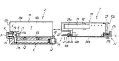
FIG. 3 is a longitudinal side elevation of FIG. 1.
FIG. 4 is a side elevation illustrating a condition where an electrode needle cartridge and a main body block in the ionizer are separated.
FIG. 5 is a partial side elevation illustrating the electrode needle cartridge in a condition where an electrode needle is detached.
FIG. 6 is a partial side elevation illustrating the electrode needle cartridge where parts relating to an attaching operation for the electrode needle are shown, while dismantling the same.
FIG. 7 is an enlarged cross-sectional view of a main part in FIG. 1, and is a view illustrating an operating condition different from that of FIG. 3.
FIG. 8 is a rear side elevation of the ionizer, and is a view illustrating an operating condition different from that of FIG. 2.
FIG. 9 is a cross-sectional view of a main part illustrating an internal structure in the operating condition of FIG. 8.
FIG. 10 is a rear side elevation illustrating the ionizer in a condition where a feeding connector is connected.
FIG. 11 is a cross-sectional view of a main part illustrating an internal structure in the operating condition of FIG. 10.
FIG. 12 is a cross-sectional view illustrating another construction example of a nozzle.
BEST MODE FOR CARRYING OUT THE INVENTION
FIG. 1 through FIG. 11 are views illustrating an embodiment of an ionizer according to the present invention. The ionizer is an ionizer of an alternating current (AC) type where AC high voltage is applied to an electrode needle so that an ion is generated, and is composed of an electrode needle cartridge 1 provided with an electrode needle 3 for generating the ion, and a main body block 2 provided with a nozzle 4 for blowing out air ionized by the ion generated by means of the electrode needle 3, to a workpiece.
The main body block 2 is made of an electrical insulation material such as synthetic resin or the like. Further, as is clearly understood from FIG. 4, the main body block 2 includes a base portion 6 extending in a front-and-back direction at a lower half portion of the main body block 2 in an elongated manner, and a cartridge housing portion 7 that houses the electrode needle cartridge 1, while being partitioned and formed above the base portion 6, and is formed into a long rectangular outer shape in the front-and-back direction, looking from a side.
At a tip end portion of the base portion 6, a convex step portion 8 rising upward is formed, and an upper surface 6 a of the base portion 6 is formed into a substantially flat surface without having an asperity in the front-and-back direction of the base portion 6 b including an upper surface of this convex step portion 8.
At a front end surface of the base portion 6, the nozzle 4 having a cylindrical shape, for blowing out air is attached at a position corresponding to the convex step portion 8. The nozzle 4 is made of an electrically conductive material, and serves as a ground electrode for earthing. The nozzle 4 is inserted into a nozzle attaching hole 5 formed in the base portion 6, and fixed thereto with a hooking clamp 4 a. The nozzle 4 is connected to an earthing portion, not shown, provided in the main body block 2. In an inside of the nozzle 4, a round shaped air-blowing outlet 9 serving as an electrode needle housing chamber is provided. In addition, a sleeve 10 having an electrical insulation is attached in a manner so as to surround an inner periphery of the air-blowing outlet 9. Further, at a rear end surface of the convex step portion 8, an electrode needle inserting entrance 11 for the electrode needle 3 to be inserted into or removed from the air-blowing outlet 9 of the nozzle 4 is provided in a concentric manner relative to the air-blowing outlet 9. The electrode needle inserting entrance 11 is composed of a large-diameter portion 11 a at an entrance side and a small-diameter portion 11 b at a back side.
At a position between the nozzle 4 and the small-diameter portion 11 b of the electrode needle inserting entrance 11, an air passing-through hole 12 that is allowed to communicate with the air-blowing outlet 9 is formed. The air passing-through hole 12 is once extended downward from a position between the nozzle 4 and the electrode needle inserting entrance 11, and is thereafter bent sideways and extended backward inside the base portion 6. The air passing-through hole 12 is allowed to communicate with a connecting port 13 for use in an air piping that is formed at a rear end portion of the base portion 6. To the connecting port 13, a pipe joint 14 of a simple connection type is attached, and by only plugging a piping tube into the pipe joint 14, the piping tube is configured to be connected in a retaining manner.
Accordingly, when pressure air is supplied into the air passing-through hole 12 from the piping tube, the air is blown out toward the workpiece from the air-blowing outlet 9 of the nozzle 4.
The cartridge housing portion 7 includes a side surface cover 16. As is clear from FIG. 2 and FIG. 4, the side surface cover 16 is composed of a side wall portion 16 a that covers a side surface of one side of the cartridge housing portion 7, a front wall portion 16 b that covers a front surface, and an upper wall portion 16 c that covers part of an upper surface. Portions of the side surface cover 16 corresponding to a side surface of the other side of the cartridge housing portion 7, and a rear surface thereof are open. Further, the electrode needle cartridge 1 is mounted on the upper surface 6 a of the base portion 6, and is slid forward along the upper surface 6 a as a guide in a non-rotating condition, and is fitted inside the side surface cover 16. Thereby, electrode needle cartridge 1 is housed in the cartridge housing portion 7 and connected to the main body block 2. When the electrode needle cartridge 1 is separated from the main body block 2, it is sufficient that an operation opposite to the above-described operation, which is performed when the electrode needle cartridge 1 is connected to the main body block 2, is performed.
When the ionizer is assembled by connecting the electrode needle cartridge 1 with the main body block 2 as described above, an entire shape of the ionizer is formed to be a rectangular block shape by the electrode needle cartridge 1 and the main body block 2.
The electrode needle cartridge 1 is, as is clear from FIG. 3 and FIG. 4, constructed by providing the electrode needle 3, a high voltage generating device 21 for applying high voltage to the electrode needle 3, a printed circuit board 22 where the high voltage generating device 21 is attached, and a receiving connector 25 for connecting a feeding connector 24 attached to the power cable 23 to a housing 20 made of an electrical insulation material such as synthetic resin or the like.
The housing 20 is formed into a box shape of a substantially rectangular or a similar cross-sectional shape, and is formed by joining two of left and right dish-shaped housing members confronting each other. The housing 20 has a length in a front-and-back direction approximating to the length in the front-and-back direction of the main body block 2, and a height approximating to a height of the cartridge housing portion 7. At a lower surface of a tip end portion of the housing 20, a concave step portion 26, which is fitting to and in contact with the convex step portion 8 of the main body block 2 each other, is formed. Each of the heights of the convex step portion 8 and the concave step portion 26 is approximately the same, and the lengths in the front-and-back direction are approximately the same. Further, a lower surface 20 a of the housing 20 is, including a lower surface of the concave step portion 26, formed into a substantially flat surface without having an asperity in the front-and-back direction of the housing 20, except a portion where a locking member 27, described later, is attached.
In the housing 20, at a step wall 26 a in a longitudinal direction of the concave step portion 26, the electrode needle 3 is detachably attached via a feeding terminal 30 and an electrode needle holder 31.
The feeding terminal 30 is made of a conductive material such as metal or the like. Further, as is clear from FIG. 5 and FIG. 6, the feeding terminal 30 includes an electrode needle attaching shaft portion 30 a having a column-shape and preferably, a cylindrical shape, a circular disk portion 30 b for use in sealing where an O-ring 32 is attached on an outer periphery thereof, a fitting shaft portion 30 c fitting in an attaching hole 26 b of the step wall 26 a of the housing 20, a flange-shaped hooking portion 30 d, which is in contact with and hooked on an inner surface of the housing 20, and a connecting shaft portion 30 e to be connected with the high voltage generating device 21 in an integral manner from a tip end side of the feeding terminal 30 in turn. The feeding terminal 30 is electrically connected to a terminal connecting portion 22 a on the printed circuit board 22 via a clip-type feeding plate 33 attached to the connecting shaft portion 30 e. The feeding plate 33 is formed into approximately U-shape in cross-section from a metal sheet having elasticity, and is elastically attached to the connecting shaft portion 30 e and the terminal connecting portion 22 a in a sandwiching manner.
Thus, when the feeding terminal 30 is attached to the housing 20, the circular disk portion 30 b is positioned in front of an outer part of the step wall 26 a, and the electrode needle attaching shaft portion 30 a extends out frontward from a center of a front surface of the circular disk portion 30 b in a concentric manner relative to the disk portion 30 b.
The attaching hole 26 b is formed by confronting half holes formed in the housing members each other, at a commissure of the left and right housing members in the housing 20. At this moment, the fitting shaft portion 30 c is attached inside the attaching hole 26 b by fitting and sandwiching the fitting shaft portion 30 c between the half holes.
Further, the electrode needle holder 31 is a cylindrical member formed from a material having conductivity and elasticity, such as metal or the like. The electrode needle holder 31 includes a gradually tapered circular conic retaining portion 31 a at a tip end thereof, a flange-shaped contacting portion 31 b overhanging in an outer peripheral direction at a rear end thereof, and a slit extending in an axis direction of the electrode needle holder 31 at a side face thereof. A diameter of the electrode needle holder 31 is configured to be elastically and automatically adjusted corresponding to diameters of the electrode needle 3 and the electrode needle attaching shaft portion 30 a of the feeding terminal 30 by means of the slit. A diameter D of the contacting portion 31 b is formed to be greater than a bore diameter d of the small-diameter portion 11 b of the main body block 2.
On the other hand, the electrode needle 3 includes a main body portion 3 a having a circular cylinder shape, which is closely fitting to, and electrically in contact with the electrode needle holder 31, and a gradually tapered circular conic tip end portion 3 b. The electrode needle 3 is inserted into the electrode needle holder 31 from a rear end portion side, and the tip end portion 3 b is hooked on the retaining portion 31 a of the electrode needle holder 31. Thereby, the electrode needle 3 is detachably held by the electrode needle holder 31 in a condition so that the electrode needle 31 is prevented from being pulled out forward.
Further, the electrode needle holder 31 holding the electrode needle 3 is fitted into the attaching shaft portion 30 a up to a position where the contacting portion 31 b becomes in contact with the circular disk portion 30 b. Thereby, the electrode needle 3 is attached to the feeding terminal 30 via the electrode needle holder 31. In this case, it is preferable that the electrode needle 3 is positioned within an area of the concave step portion 26, and that the tip end portion 3 b is not protruded forward from the housing 20.
By this construction, when the lower surface 20 a of the housing 20 of the electrode needle cartridge 1 is in contact with the upper surface 6 a of the base portion 6 of the main body block 2 and when the electrode needle cartridge 1 is slid forward and connected to the main block 2, as indicated by an arrow in FIG. 4, the electrode needle 3 is inserted into inside the nozzle 4 from the electrode needle inserting entrance 11, and the tip end portion 3 b of the electrode needle 3 is brought to be positioned inside the air-blowing outlet 9, specifically inside the sleeve 10. At this moment, the circular disk portion 30 b is fitted into the large-diameter portion 11 a of the electrode needle inserting entrance 11, and the O-ring 32 seals a space between an outer periphery of the circular disk portion 30 b and an inner periphery of the large-diameter portion 11 a.
Further, the contacting portion 31 b of the electrode needle holder 31 is in contact with a mouth edge of the small-diameter portion 11 b and hooked thereto. In addition, the contacting portion 31 b is sandwiched between the mouth edge and the circular disk portion 30 b, and thereby the electrode needle holder 31 is prevented from moving to a nozzle 4 side while passing through the small-diameter portion 11 b.
When the maintenance for the electrode needle 3 is performed, the electrode needle cartridge 1 is slid backward along the upper surface 6 a of the base portion 6 and is removed from the main body block 2. The electrode needle 3 is thereby taken out backward from the nozzle 4. Therefore, a removal operation for the stain on the electrode needle 3, exchanging operation for the electrode needle 3, or the like can be performed.
The high voltage generating device 21 is mounted on the printed circuit board 22 where a printed wiring operation is performed, and is provided in an inside of the housing 20 via the printed circuit board 22. Further, at a rear end portion of the housing 20, the receiving connector 25 is attached while a connecting port 25 a thereof is faced to a backside of the housing 20, and is connected to the high voltage generating device 21 via the printed wiring on the printed circuit board 22.
Further, at the rear end portion of the housing 20 of the electrode needle cartridge 1, the locking member 27 for locking the electrode needle cartridge 1 and the main body block 2 in a connected condition is provided. The locking member 27 includes a main shaft portion 27 a supported so as to be rotatable around an axis line L, as a center, in a front-and-back direction in the housing 20, a hooking portion 27 b formed at a tip end of the main shaft portion 27 a so as to protrude sideward of the main shaft portion 27 a, and hooked or unhooked on a hooking hole 36 of the main body block 2 by forward-and reverse rotation of the main shaft portion 27 a, and a handle portion 27 c, which is formed at a rear end portion of the main shaft portion 27 a in a manner so as to be protruded sideward while keeping an angle difference at 90 degrees around the axis line L relative to the hooking portion 27 b, for performing a rotating operation for the main shaft portion 27 a. The locking member 27 is disposed at a position in the vicinity of the receiving connector 25.
Furthermore, as illustrated in FIG. 3 and FIG. 11, in a locking condition where the hooking portion 27 b is hooked on the hooking hole 36, the handle portion 27 c is horizontally positioned beneath the connecting port 25 a of the receiving connector 25 and occupies a locking position where the handle portion 27 c is retracted from the connecting port 25 a as illustrated in FIG. 10, and in a condition where the hooking portion 27 b is tripped from the hooking hole 36, and the locking operation is released, as illustrated in FIG. 7 and FIG. 9, the handle portion 27 c is located in front of the connecting port 25 a of the receiving connector 25 and configured to occupy a locking operation releasing position where the handle portion 27 c covers part of the connecting port 25 a, as illustrated in FIG. 7 and FIG. 8. Accordingly, when the handle portion 27 c is located at the locking position, the feeding connector 24 can freely be attached to or detached from the receiving connector 25. When the handle portion 27 c is located at the locking operation releasing position, the feeding connector 24 cannot be connected to the receiving connector 25.
In other words, in a case that the electrode needle cartridge 1 is removed from the main body block 2 when the maintenance for the electrode needle 3 is performed, the handle portion 27 c located at the locking position cannot be rotated to the locking operation releasing position. This is because, when the feeding connector 24 is connected to the receiving connector 25, namely in a condition that the high voltage generating device 21 is connected to a power source, a rotating operation of the handle portion 27 c is limited by the feeding connector 24. Thereby, a risk such as that the electrode needle cartridge 1 is removed without turning off the power distribution for the electrode needle 3 is avoided and high safety is secured.
However, when the feeding connector 24 is removed from the receiving connector 25, the handle portion 27 c can be rotated toward the locking operation releasing position, therefore the maintenance for the electrode needle 3 can safely be performed while removing the electrode needle cartridge 1.
The ionizer having the construction is used by connecting the feeding connector 24 of the power cable 23 to the receiving connector 25, and by connecting an air piping tube to the connecting port 13 for use in piping. When the ionizer is used, the locking member 27 locks the main body block 2 and the electrode needle cartridge 1 in a connected condition while the handle portion 27 c occupies the locking position as illustrated in FIG. 10, and the hooking portion 27 b is hooked on the hooking hole 36 of the main body block 2.
When the power source is turned on in the condition, the AC high voltage is applied from the high voltage generating device 21 to the electrode needle 3, the electrode needle 3 generates a corona discharge and positive and negative ions are alternately generated.
On the other hand, air is supplied to the nozzle 4 through the air passing-through hole 12, and the air is blown out from the air-blowing outlet 9. However, the air takes in the ion generated from the electrode needle 3 resulting in becoming ionized air. The ionized air is blown out toward a workpiece in this condition.
When a need for the maintenance occurs when the electrode needle 3 gets stained, the locking operation is released by rotating the handle portion 27 c of the locking member 27 in the locking operation releasing position after removing the feeding connector 24 from the receiving connector 25, as illustrated in FIG. 7. Further, the electrode needle cartridge 1 is slid backward, and is removed from the main body block 2, as illustrated in FIG. 4, and a cleaning operation or an exchanging operation for the electrode needle 3 is performed. In a case that the electrode needle 3 is removed for performing the cleaning operation or the exchanging operation therefor, it is sufficient that the electrode needle holder 31 is taken out from the electrode needle attaching shaft portion 30 a of the feeding terminal 30, and the electrode needle 3 is taken out from the electrode needle holder 31, as illustrated in FIG. 5 and FIG. 6.
In this case, the attaching and detaching operations for the electrode needle 3, or the attaching and detaching operations for the electrode needle attaching shaft portion 30 a are easy because the electrode needle holder 31 is provided with elasticity and is provided with the slit in an axis direction.
Thus, in the ionizer having the construction, the electrode needle cartridge 1 is provided with the electrode needle 3, the high voltage generating device 21, and the receiving connector 25, and the main body block 2 is provided with the air-blowing outlet 9, the air passing-through hole 12, and the connecting port 13. Thereby, the electricity-relating parts and portions, and the air-relating parts and portions can rationally be distributed into separate members, and supported. As a result, an entire construction can be simplified and at the same time, the attaching and detaching operations for the electrode needle cartridge 1 and the main body block 2 can simply and safely be performed. In addition, since the separating operation for the electrode needle cartridge 1 and the main body block 2 can safely be performed by means of the locking member 27, safety of the maintenance for the electrode needle 3 is also excellent.
Incidentally, although the ionizer in the embodiment is an ionizer of an alternating current (AC) type, the present invention can also be applied to an ionizer of a direct current (DC) type. In this case, two of positive and negative electrode needles 3 are held in the electrode needle cartridge 1, and the electrode needles 3 are housed in the air-blowing outlet 9 of the main body block 2.
Further, in the embodiment illustrated, the nozzle 4 is provided with conductivity and the nozzle 4 serves as the ground electrode. However, the nozzle 4 may be formed with a non-conductive material such as synthetic resin or the like, and the ground electrode may separately be provided. For example, as illustrated in FIG. 12, a ground electrode 37 having conductivity may be held by the circular cylinder-shaped nozzle 4 made of synthetic resin. In this case, although the ground electrode 37 is preferable to have a circular cylinder shape, the cross-section of the ground electrode 37 is not always necessary to be a complete circular shape. Namely, the ground electrode 37 may have a C-shaped cross-section having a slit in an axis direction at a side surface. Alternatively, as illustrated, a plurality of (for example, two to four in number) ground electrodes 37 each having an arc shape or a shape similar thereto in cross-section may be held while disposing in an approximately cylindrical manner in a condition where a gap intervenes inbetween each other.
Each of the ground electrodes 37 can be attached to an inner periphery, an outer periphery, or in a wall thickness of the nozzle 4. In a case that the ground electrode 37 is attached to the inner periphery of the nozzle 4, as illustrated in FIG. 12, so as to avoid a contact of the ground electrode 37 with the electrode needle 3, an electrical insulation sleeve may be attached along an inner periphery of the ground electrode 37 as needed.
Incidentally, in FIG. 12, a numeral 3 denotes the electrode needle, a numeral 9 denotes the air-blowing outlet, and a numeral 31 denotes the electrode needle holder, respectively.

Claims (12)

1. An ionizer constructed by separatably connecting an electrode needle cartridge comprising an electrode needle for generating an ion, and a main body block comprising an air-blowing outlet serving as an electrode needle housing chamber in a condition where the electrode needle is inserted into the air-blowing outlet, and constructed such that the electrode needle is inserted into or removed from the air-blowing outlet, from an electrode needle inserting entrance at a rear end portion side of the air-blowing outlet when the electrode needle cartridge and the main body block are connected or separated,
wherein the electrode needle cartridge includes the detachable electrode needle and a high voltage generating device for applying high voltage to the electrode needle, and wherein the main body block includes an air passing-through hole for supplying air to the air-blowing outlet and a connecting port (13) for connecting an air piping to the air passing-through hole.
2. The ionizer according to claim 1, wherein the ionizer is constructed such that the electrode needle cartridge is connected to or separated from the main body block and the electrode needle is inserted into or removed from the air-blowing outlet, by only sliding the electrode needle cartridge in a front-and-back direction without rotating the same.
3. The ionizer according to claim 1, wherein a convex step portion and a concave step portion being in contact with each other when the same are connected are formed at a front end portion of the main body block and a front end portion of the electrode needle cartridge, respectively, and wherein the air-blowing outlet is formed at a position of the convex step portion and the electrode needle is formed at a position of the concave step portion.
4. The ionizer according to claim 3, wherein the main body block includes a base portion provided with the air-blowing outlet, the air passing-through hole, and the connecting port, and a cartridge housing portion for housing the electrode needle cartridge while being positioned on the base portion, and wherein at an upper surface of a tip end portion of the base portion, the convex step portion rising upward is formed, and at a front surface of the convex step portion, the air-blowing outlet is provided, and at a rear surface of the convex step portion, the electrode needle inserting entrance is provided in a concentric manner relative to the air-blowing outlet, and wherein the electrode needle cartridge has a length in a front-and-back direction approximating to the main body block, and includes the concave step portion conforming to the convex step portion at a lower surface of a tip end portion, and wherein the electrode needle is attached to a position of the concave step portion in a condition of extending forward, and wherein the electrode needle cartridge is configured to be attached to and detached from the main body block by sliding in the front-and-back direction along an upper surface of the base portion as a guide.
5. The ionizer according to claim 1, wherein the electrode needle is detachably and elastically held by a conductive electrode needle holder having elasticity, and wherein the electrode needle holder is detachably and elastically attached to a column-shaped feeding terminal protruding outward from a housing of the electrode needle cartridge.
6. The ionizer according to claim 5, wherein the electrode needle inserting entrance is composed of a large diameter portion at an entrance side and a small diameter portion at a rear side, and the electrode needle holder includes a flange-shaped contacting portion at a base end portion, and wherein a diameter of the contacting portion is formed to be greater than a bore diameter of the small diameter portion, and when the electrode needle held by the electrode needle holder is inserted into the air-blowing outlet from the electrode needle inserting entrance, frontward movement of the electrode needle holder is configured to be limited by that the contacting portion is in contact with and hooked on a mouth edge of the small diameter portion.
7. The ionizer according to claim 1, wherein the ionizer includes a locking member for locking the electrode needle cartridge and the main body block in a connected condition, and the locking member is configured to limit an operation for releasing a locking operation in a condition where the high voltage generating device is connected to a power source.
8. The ionizer according to claim 7, wherein the electrode needle cartridge includes a receiving connector for connecting the feeding connector attached to a power cable, and wherein the locking member includes a main shaft portion rotatably supported by the electrode needle cartridge, a hooking portion hooked on and tripped from the main body block by forward-and-reverse rotation of the main shaft portion, and a handle portion for performing a rotating operation for the main shaft portion, and wherein when the feeding connector is connected to the receiving connector, a rotation of the handle portion in a direction where the locking operation is released is configured to be limited by means of the feeding connector by that the handle portion is disposed in a vicinity of the connecting port of the receiving connector.
9. The ionizer according to claim 3, wherein the electrode needle is detachably and elastically held by a conductive electrode needle holder having elasticity, and wherein the electrode needle holder is detachably and elastically attached to a column-shaped feeding terminal protruding outward from a housing of the electrode needle cartridge.
10. The ionizer according to claim 9, wherein the electrode needle inserting entrance is composed of a large diameter portion at an entrance side and a small diameter portion at a rear side, and the electrode needle holder includes a flange-shaped contacting portion at a base end portion, and wherein a diameter of the contacting portion is formed to be greater than a bore diameter of the small diameter portion, and when the electrode needle held by the electrode needle holder is inserted into the air-blowing outlet from the electrode needle inserting entrance, frontward movement of the electrode needle holder is configured to be limited by that the contacting portion is in contact with and hooked on a mouth edge of the small diameter portion.
11. The ionizer according to claim 3, wherein the ionizer includes a locking member for locking the electrode needle cartridge and the main body block in a connected condition, and the locking member is configured to limit an operation for releasing a locking operation in a condition where the high voltage generating device is connected to a power source.
12. The ionizer according to claim 11, wherein the electrode needle cartridge includes a receiving connector for connecting the feeding connector attached to a power cable, and wherein the locking member includes a main shaft portion rotatably supported by the electrode needle cartridge, a hooking portion hooked on and tripped from the main body block by forward-and-reverse rotation of the main shaft portion, and a handle portion for performing a rotating operation for the main shaft portion, and wherein when the feeding connector is connected to the receiving connector, a rotation of the handle portion in a direction where the locking operation is released is configured to be limited by means of the feeding connector by that the handle portion is disposed in a vicinity of the connecting port of the receiving connector.
US12/015,010 2007-02-14 2008-01-16 Ionizer Active 2028-09-26 US7695552B2 (en)

Applications Claiming Priority (2)

Application Number Priority Date Filing Date Title
JP2007-034017 2007-02-14
JP2007034017A JP4811731B2 (en) 2007-02-14 2007-02-14 Ionizer

Publications (2)

Publication Number Publication Date
US20080190294A1 US20080190294A1 (en) 2008-08-14
US7695552B2 true US7695552B2 (en) 2010-04-13

Family

ID=39646244

Family Applications (1)

Application Number Title Priority Date Filing Date
US12/015,010 Active 2028-09-26 US7695552B2 (en) 2007-02-14 2008-01-16 Ionizer

Country Status (6)

Country Link
US (1) US7695552B2 (en)
JP (1) JP4811731B2 (en)
KR (1) KR100983018B1 (en)
CN (1) CN101247696B (en)
DE (1) DE102008007990B4 (en)
TW (1) TWI357288B (en)

Cited By (6)

* Cited by examiner, † Cited by third party
Publication number Priority date Publication date Assignee Title
US20110199714A1 (en) * 2010-02-17 2011-08-18 Koganei Corporation Ion generator
US20130008315A1 (en) * 2011-07-05 2013-01-10 Dawn White System and method for energy and particle extraction from an exhaust system
US8451578B1 (en) * 2010-02-12 2013-05-28 Western Digital Technologies, Inc. Hard drive particle cleaning system and method
US9660425B1 (en) 2015-12-30 2017-05-23 Plasma Air International, Inc Ion generator device support
US9847623B2 (en) 2014-12-24 2017-12-19 Plasma Air International, Inc Ion generating device enclosure
US20210356148A1 (en) * 2020-05-15 2021-11-18 Genano Oy Air purifying device, arrangement and method for separating materials from a gas flow

Families Citing this family (11)

* Cited by examiner, † Cited by third party
Publication number Priority date Publication date Assignee Title
JP4759430B2 (en) * 2006-04-13 2011-08-31 株式会社コガネイ Static eliminator and discharge module
KR101001454B1 (en) * 2009-01-23 2010-12-14 삼성모바일디스플레이주식회사 Electrostatic Chuck and Manufacturing Device of Organic Light Emitting Diode Having the Same
CH702246A1 (en) 2009-11-18 2011-05-31 Beat Mueller Electrostatic dust filter system, support for an electrode and electrode therefor.
DE102010054747A1 (en) 2010-12-16 2012-06-21 Arnulf Deinzer Ionizer for dissipation of electrostatic charges for producing air jet to clean dust from e.g. semi-finished product, has needle-shaped electrodes inserted into additional elements that are connected to blower as nozzles
US9815072B2 (en) 2011-10-12 2017-11-14 1366 Technologies Inc. Apparatus for depositing a thin layer of polymer resist on a substrate
KR101632519B1 (en) 2011-12-13 2016-06-21 코요 베어링즈 노쓰 아메리카 엘엘씨 Bearing outer race
CN102711351A (en) * 2012-01-06 2012-10-03 无锡市中联电子设备有限公司 Integrated ion nozzle
US8730642B2 (en) * 2012-09-20 2014-05-20 Shenzhen China Star Optoelectronics Technology Co., Ltd. Stacker and static elimination device for the same
JP2014157668A (en) * 2013-02-14 2014-08-28 Panasonic Industrial Devices Sunx Co Ltd Discharge electrode and static eliminator
US9293895B2 (en) * 2013-05-17 2016-03-22 Illinois Tool Works Inc. Ionizing bar for air nozzle manifold
JP6824286B2 (en) * 2016-12-14 2021-02-03 シャープ株式会社 Refrigerator, ion generator and storage

Citations (29)

* Cited by examiner, † Cited by third party
Publication number Priority date Publication date Assignee Title
US1995790A (en) * 1932-07-26 1935-03-26 Int Precipitation Co Apparatus for electrical precipitation
US2209798A (en) * 1936-09-12 1940-07-30 Union Oil Co Electrostatic fractionator
US2381578A (en) * 1936-09-12 1945-08-07 Union Oil Co Apparatus and method for coalescing foam
US3156847A (en) * 1960-04-21 1964-11-10 Simco Co Inc Ionizing air gun
US3195819A (en) * 1962-03-14 1965-07-20 Watanabe Tamotsu Spray nozzle for coating articles
US3206625A (en) * 1961-07-14 1965-09-14 Litton Systems Inc Hydrodynamic high voltage generator
US3476095A (en) * 1966-06-21 1969-11-04 Plastus Sa Method and means for feeding internal combustion engines
US3768258A (en) * 1971-05-13 1973-10-30 Consan Pacific Inc Polluting fume abatement apparatus
US3879986A (en) * 1973-10-05 1975-04-29 Atomic Energy Commission Parallel point to plane electrostatic precipitator particle size sampler
US3957374A (en) * 1974-02-01 1976-05-18 Carl Zeiss-Stiftung Apparatus for obtaining samples of dusts for analysis by spectrochemical examination
JPS5678645A (en) * 1979-12-03 1981-06-27 Ono Gijutsu Kenkyusho:Kk Air purifier
US4391614A (en) * 1981-11-16 1983-07-05 Kelsey-Hayes Company Method and apparatus for preventing lubricant flow from a vacuum source to a vacuum chamber
US4477263A (en) * 1982-06-28 1984-10-16 Shaver John D Apparatus and method for neutralizing static electric charges in sensitive manufacturing areas
US4741746A (en) * 1985-07-05 1988-05-03 University Of Illinois Electrostatic precipitator
US5149339A (en) * 1991-03-11 1992-09-22 California Institute Of Technology Rotary device for removing particulates from a gas stream
US5217510A (en) * 1991-10-18 1993-06-08 The United States Of America As Represented By The United States Department Of Energy Apparatus for preventing particle deposition from process streams on optical access windows
US5518531A (en) * 1994-05-05 1996-05-21 Joannu; Constantinos J. Ion injector for air handling systems
US5667563A (en) * 1995-07-13 1997-09-16 Silva, Jr.; John C. Air ionization system
US6004375A (en) * 1994-01-13 1999-12-21 Gutsch; Andreas Process and apparatus to treat gasborne particles
US6464754B1 (en) * 1999-10-07 2002-10-15 Kairos, L.L.C. Self-cleaning air purification system and process
US6506232B2 (en) * 2001-03-13 2003-01-14 Ion Systems, Inc. Air ionization apparatus and method for efficient generation and cleaning
US6635105B2 (en) * 2000-07-11 2003-10-21 Ing. Walter Hengst Gmbh & Co. Kg Electrostatic precipitator
JP2004228069A (en) 2002-11-29 2004-08-12 Sunx Ltd Static eliminator
US7115153B2 (en) * 2002-07-12 2006-10-03 Hengst Gmbh & Co. Kg Electric separator with a rinsing cleaning system
US20060278081A1 (en) * 2005-06-14 2006-12-14 Samsung Gwangju Electronics Co., Ltd. Cyclone dust collecting device for vacuum cleaner
US20070034082A1 (en) * 2005-08-10 2007-02-15 Adair Joel E Air purifier
US20070126363A1 (en) 2005-12-05 2007-06-07 Smc Corporation Ionizer with drop-off prevention device for electrode
US7465340B2 (en) * 2005-12-05 2008-12-16 Smc Corporation Ionizer with parts-extension unit
US7497898B2 (en) * 2006-10-31 2009-03-03 Smc Corporation Ionizer

Family Cites Families (17)

* Cited by examiner, † Cited by third party
Publication number Priority date Publication date Assignee Title
JPH0747838Y2 (en) * 1991-09-18 1995-11-01 春日電機株式会社 Air jet static eliminator for paper sheet separation
US5550703A (en) * 1995-01-31 1996-08-27 Richmond Technology, Inc. Particle free ionization bar
JP4636710B2 (en) * 2001-03-01 2011-02-23 株式会社キーエンス Ionizer
JP4903942B2 (en) * 2001-03-15 2012-03-28 株式会社キーエンス Ion generator
JP2003243199A (en) * 2002-02-21 2003-08-29 Koganei Corp Static charge eliminator
JP2004213988A (en) * 2002-12-27 2004-07-29 Sunx Ltd Static eliminator
JP4226359B2 (en) * 2003-03-10 2009-02-18 株式会社キーエンス Static eliminator
US6807044B1 (en) * 2003-05-01 2004-10-19 Ion Systems, Inc. Corona discharge apparatus and method of manufacture
JP4363903B2 (en) * 2003-06-05 2009-11-11 株式会社キーエンス Static eliminator
JP2005166268A (en) * 2003-11-28 2005-06-23 Sunx Ltd Static eliminator
TWI362682B (en) * 2003-12-02 2012-04-21 Keyence Co Ltd Ionizer and discharge electrode assembly mounted therein
JP2005196977A (en) * 2003-12-26 2005-07-21 Sunx Ltd Static eliminator
KR200377019Y1 (en) 2004-11-16 2005-03-11 (주)해강 Electrostatic remove apparatus
JP4345060B2 (en) * 2004-11-30 2009-10-14 Smc株式会社 Ionizer
JP4704192B2 (en) * 2005-11-09 2011-06-15 株式会社キーエンス Electrode needle unit of ionizer and ionizer
EP1791232B1 (en) * 2005-11-25 2014-01-08 Samsung Electronics Co., Ltd. Air cleaning apparatus using an ion generating apparatus
KR200424015Y1 (en) 2006-05-23 2006-08-14 하이-팩 인코포레이티드 The structured electrostatic eliminator without a fuse

Patent Citations (29)

* Cited by examiner, † Cited by third party
Publication number Priority date Publication date Assignee Title
US1995790A (en) * 1932-07-26 1935-03-26 Int Precipitation Co Apparatus for electrical precipitation
US2209798A (en) * 1936-09-12 1940-07-30 Union Oil Co Electrostatic fractionator
US2381578A (en) * 1936-09-12 1945-08-07 Union Oil Co Apparatus and method for coalescing foam
US3156847A (en) * 1960-04-21 1964-11-10 Simco Co Inc Ionizing air gun
US3206625A (en) * 1961-07-14 1965-09-14 Litton Systems Inc Hydrodynamic high voltage generator
US3195819A (en) * 1962-03-14 1965-07-20 Watanabe Tamotsu Spray nozzle for coating articles
US3476095A (en) * 1966-06-21 1969-11-04 Plastus Sa Method and means for feeding internal combustion engines
US3768258A (en) * 1971-05-13 1973-10-30 Consan Pacific Inc Polluting fume abatement apparatus
US3879986A (en) * 1973-10-05 1975-04-29 Atomic Energy Commission Parallel point to plane electrostatic precipitator particle size sampler
US3957374A (en) * 1974-02-01 1976-05-18 Carl Zeiss-Stiftung Apparatus for obtaining samples of dusts for analysis by spectrochemical examination
JPS5678645A (en) * 1979-12-03 1981-06-27 Ono Gijutsu Kenkyusho:Kk Air purifier
US4391614A (en) * 1981-11-16 1983-07-05 Kelsey-Hayes Company Method and apparatus for preventing lubricant flow from a vacuum source to a vacuum chamber
US4477263A (en) * 1982-06-28 1984-10-16 Shaver John D Apparatus and method for neutralizing static electric charges in sensitive manufacturing areas
US4741746A (en) * 1985-07-05 1988-05-03 University Of Illinois Electrostatic precipitator
US5149339A (en) * 1991-03-11 1992-09-22 California Institute Of Technology Rotary device for removing particulates from a gas stream
US5217510A (en) * 1991-10-18 1993-06-08 The United States Of America As Represented By The United States Department Of Energy Apparatus for preventing particle deposition from process streams on optical access windows
US6004375A (en) * 1994-01-13 1999-12-21 Gutsch; Andreas Process and apparatus to treat gasborne particles
US5518531A (en) * 1994-05-05 1996-05-21 Joannu; Constantinos J. Ion injector for air handling systems
US5667563A (en) * 1995-07-13 1997-09-16 Silva, Jr.; John C. Air ionization system
US6464754B1 (en) * 1999-10-07 2002-10-15 Kairos, L.L.C. Self-cleaning air purification system and process
US6635105B2 (en) * 2000-07-11 2003-10-21 Ing. Walter Hengst Gmbh & Co. Kg Electrostatic precipitator
US6506232B2 (en) * 2001-03-13 2003-01-14 Ion Systems, Inc. Air ionization apparatus and method for efficient generation and cleaning
US7115153B2 (en) * 2002-07-12 2006-10-03 Hengst Gmbh & Co. Kg Electric separator with a rinsing cleaning system
JP2004228069A (en) 2002-11-29 2004-08-12 Sunx Ltd Static eliminator
US20060278081A1 (en) * 2005-06-14 2006-12-14 Samsung Gwangju Electronics Co., Ltd. Cyclone dust collecting device for vacuum cleaner
US20070034082A1 (en) * 2005-08-10 2007-02-15 Adair Joel E Air purifier
US20070126363A1 (en) 2005-12-05 2007-06-07 Smc Corporation Ionizer with drop-off prevention device for electrode
US7465340B2 (en) * 2005-12-05 2008-12-16 Smc Corporation Ionizer with parts-extension unit
US7497898B2 (en) * 2006-10-31 2009-03-03 Smc Corporation Ionizer

Non-Patent Citations (1)

* Cited by examiner, † Cited by third party
Title
U.S. Appl. No. 11/877,269, filed Oct. 23, 2007, Sato, et al.

Cited By (14)

* Cited by examiner, † Cited by third party
Publication number Priority date Publication date Assignee Title
US8451578B1 (en) * 2010-02-12 2013-05-28 Western Digital Technologies, Inc. Hard drive particle cleaning system and method
US20110199714A1 (en) * 2010-02-17 2011-08-18 Koganei Corporation Ion generator
US8355237B2 (en) 2010-02-17 2013-01-15 Koganei Corporation Ion generator
US20130008315A1 (en) * 2011-07-05 2013-01-10 Dawn White System and method for energy and particle extraction from an exhaust system
US10297984B2 (en) 2014-12-24 2019-05-21 Plasma Air International, Inc Ion generating device enclosure
US9847623B2 (en) 2014-12-24 2017-12-19 Plasma Air International, Inc Ion generating device enclosure
US10978858B2 (en) 2014-12-24 2021-04-13 Plasma Air International, Inc Ion generating device enclosure
US9985421B2 (en) 2015-12-30 2018-05-29 Plasma Air International, Inc Ion generator device support
US10014667B2 (en) 2015-12-30 2018-07-03 Plasma Air International, Inc Ion generator device support
US10153623B2 (en) 2015-12-30 2018-12-11 Plasma Air International, Inc Ion generator device support
US9660425B1 (en) 2015-12-30 2017-05-23 Plasma Air International, Inc Ion generator device support
US10439370B2 (en) 2015-12-30 2019-10-08 Plasma Air International, Inc Ion generator device support
US11018478B2 (en) 2015-12-30 2021-05-25 Plasma Air International, Inc Ion generator device support
US20210356148A1 (en) * 2020-05-15 2021-11-18 Genano Oy Air purifying device, arrangement and method for separating materials from a gas flow

Also Published As

Publication number Publication date
US20080190294A1 (en) 2008-08-14
TWI357288B (en) 2012-01-21
KR20080076783A (en) 2008-08-20
CN101247696B (en) 2013-01-09
DE102008007990A1 (en) 2008-08-28
JP4811731B2 (en) 2011-11-09
DE102008007990B4 (en) 2016-02-25
CN101247696A (en) 2008-08-20
KR100983018B1 (en) 2010-09-17
JP2008198533A (en) 2008-08-28
TW200843562A (en) 2008-11-01

Similar Documents

Publication Publication Date Title
US7695552B2 (en) Ionizer
KR101167958B1 (en) Plasma torch, plasma torch nozzle, and plasma working machine
US8355237B2 (en) Ion generator
KR101111377B1 (en) Static eliminator and electric discharge module
RU2496619C2 (en) Attachment of gas nozzle
CN103477720B (en) Neutralizer
US5440094A (en) Plasma arc torch with removable anode ring
JP2004228069A (en) Static eliminator
JP5539848B2 (en) Ion generator
KR100955456B1 (en) Ionizer
KR100788186B1 (en) Blower type ionizer includes chamber which can be slided out
CN210994841U (en) Powder gun with electric needle convenient to replace
CN113764951A (en) Replaceable negative ion carbon brush and mounting structure thereof
JPS61279373A (en) Plasma torch
KR100495711B1 (en) Processing chamber of FPD manufacturing machine comprising showerhead
JP2721703B2 (en) Tig welding torch
EP2375875B1 (en) Swirler for plasma cutting torches
RU97073U1 (en) ELECTRODE WELDING TORCH
KR200271807Y1 (en) Insulation bushing of a ion beam generation apparatus
TWI836527B (en) Apparatus and ionizing bar for silicon based charge neutralization
JP2667005B2 (en) Tig welding torch
JP5654400B2 (en) Static eliminator
JP2009277434A (en) Ion source
KR20150100466A (en) Apparatus for generating plasma

Legal Events

Date Code Title Description
AS Assignment

Owner name: SMC CORPORATION, JAPAN

Free format text: ASSIGNMENT OF ASSIGNORS INTEREST;ASSIGNORS:SATO, TOSHIO;TSUCHIYA, GEN;REEL/FRAME:020372/0409

Effective date: 20080107

Owner name: SMC CORPORATION,JAPAN

Free format text: ASSIGNMENT OF ASSIGNORS INTEREST;ASSIGNORS:SATO, TOSHIO;TSUCHIYA, GEN;REEL/FRAME:020372/0409

Effective date: 20080107

STCF Information on status: patent grant

Free format text: PATENTED CASE

FEPP Fee payment procedure

Free format text: PAYOR NUMBER ASSIGNED (ORIGINAL EVENT CODE: ASPN); ENTITY STATUS OF PATENT OWNER: LARGE ENTITY

FPAY Fee payment

Year of fee payment: 4

MAFP Maintenance fee payment

Free format text: PAYMENT OF MAINTENANCE FEE, 8TH YEAR, LARGE ENTITY (ORIGINAL EVENT CODE: M1552)

Year of fee payment: 8

MAFP Maintenance fee payment

Free format text: PAYMENT OF MAINTENANCE FEE, 12TH YEAR, LARGE ENTITY (ORIGINAL EVENT CODE: M1553); ENTITY STATUS OF PATENT OWNER: LARGE ENTITY

Year of fee payment: 12