US7689565B1 - Methods and apparatus for synchronizing network management data - Google Patents
Methods and apparatus for synchronizing network management data Download PDFInfo
- Publication number
- US7689565B1 US7689565B1 US11/477,026 US47702606A US7689565B1 US 7689565 B1 US7689565 B1 US 7689565B1 US 47702606 A US47702606 A US 47702606A US 7689565 B1 US7689565 B1 US 7689565B1
- Authority
- US
- United States
- Prior art keywords
- staging
- database
- changeset
- transaction
- dataset
- Prior art date
- Legal status (The legal status is an assumption and is not a legal conclusion. Google has not performed a legal analysis and makes no representation as to the accuracy of the status listed.)
- Active, expires
Links
Images


Classifications
-
- G—PHYSICS
- G06—COMPUTING; CALCULATING OR COUNTING
- G06F—ELECTRIC DIGITAL DATA PROCESSING
- G06F16/00—Information retrieval; Database structures therefor; File system structures therefor
- G06F16/20—Information retrieval; Database structures therefor; File system structures therefor of structured data, e.g. relational data
- G06F16/27—Replication, distribution or synchronisation of data between databases or within a distributed database system; Distributed database system architectures therefor
Definitions
- a storage area network is a collection of data storage systems that are networked with a number of host computer systems that operate as servers to access data stored in the data storage systems.
- Elements of a typical conventional storage area network implementation include one or more connectivity devices such as high speed data switches or routers that interconnect the various data storage systems to each other and to one or more host or server computer systems (servers) that require access to (e.g., read and/or write) the data in the data storage systems on behalf of client software applications and/or client computer systems.
- connectivity devices such as high speed data switches or routers that interconnect the various data storage systems to each other and to one or more host or server computer systems (servers) that require access to (e.g., read and/or write) the data in the data storage systems on behalf of client software applications and/or client computer systems.
- a developer or administrator of such a storage area network environment may install one or more distributed storage area network management software applications within the storage area network to manage or administer the various elements (i.e., devices, computer systems, storage systems, etc.) that operate within the storage area network.
- a network manager i.e., a user responsible for management of the storage area network operates the network management software application to perform management tasks such as performance monitoring, network analysis and remote configuration and administration of the various components operating within the storage area network.
- a typical conventional storage area network management software application may have several different software components that execute independently of each other on different computer systems but that collectively interoperate together to perform network management.
- conventional designs of storage area network management applications can include console, server, agent and storage software components.
- the server component operates as a central control process within the storage area network management application and coordinates communication between the console, storage and agent components.
- the console component often executes within a dedicated storage area network management workstation to allow the network administrator to visualize and remotely control and manage the various elements within the storage area network that are graphically represented within the console.
- Certain console applications include Graphical User Interface (GUI) software programs that enable network managers to graphically manage, control and configure various types of hardware and software resources or managed entities associated with a corresponding managed network.
- GUI Graphical User Interface
- rendering the graphical user interface enables the network manager to graphically select, interact with, and manage local or remote devices and associated software processes operating in the network.
- a network manager is able to manage hardware and software entities such as storage devices, peripherals, network data communications devices, and so forth associated with the network.
- a network manager may select a displayed icon representing a corresponding resource (i.e., a managed resource) in the storage area network and apply a management command in order to display corresponding management information.
- SANs Storage Area Networks
- elements such as storage arrays, switches, hosts and databases all inter-networked. These elements may exist in number by the hundreds in large installations of such environments. These elements in turn may consist of several hundred or thousands of manageable elements or managed resources such as storage devices, storage and switch ports, database instances, host devices and file systems, and the like. Management of such environments is a daunting task and typically requires Storage Resource Management solutions such as EMC's Control Center (ECC) family of products, available from EMC Corporation of Hopkinton, Mass. ECC includes agents that are deployed on host computer systems in a SAN for the purpose of gathering data about the various managed resources in the SAN.
- ECC EMC's Control Center
- the agents periodically collect network management data on components such as hosts, switches and storage systems that process and persist data, as well as on applications that use persisted information to enable the management of these environments.
- agents collect data associated with the managed resources, and that data is inserted into databases for use within Storage Resource Management solutions, such as ECC.
- ECC identifies the entire process of retrieving the collected data from agents to data persistence as a transaction.
- Agents collect data periodically, such as nightly, on the resources and engage in a transaction to send the collected data to the ECC repository for access by ECC applications such as console and server processes that allow SAN administrators to manage the SAN.
- an agent collects data associated with the managed resources such as data storage systems, hosts, switches and the like.
- the agent transmits the data to a production database where the data is inserted.
- that data can be displayed on the console for the network manager to view.
- a set of managed object data collected by an agent from a resource such as a Symmetrix disk array system is a very large amount of data to be placed into the production database.
- the agent divides the collected set of data into manageable partitions prior to being transmitted to the production database. The agent then transmits each partition, one by one, to the production database for storage.
- problems can occur when one or more partitions are not successfully inserted into the production database, resulting in partial data being delivered to the console and resulting in the inability to access the production database during updates from agents (i.e., during transaction processing).
- Use of a staging database as an interim processing step resolves this problem as described in that co-pending and related patent application.
- a staging database receives each partition serially from the agent, and the data in each partition is inserted into the staging database first, rather than the production database.
- the production database synchronizes with the staging database that is a faster process than transferring partition data directly into the production database as is done in conventional systems.
- the staging database can be maintained accessible in a read-only mode so that consoles, server processes and other SAN management processes can still at least view the production database, as opposed to having to take this database offline during transaction processing to avoid inconsistent view of data.
- Embodiments disclosed herein operate in conjunction with the staging system described in the above co-pending patent and allow the system to track all changes made to the staging database during transaction processing. By tracking these changes in a changeset, once a transaction has completed and has been committed to the staging database, the system disclosed herein operates to cause all changes to be then reflected or synchronized with the production database.
- embodiments described herein provide a system that includes a computer system executing a database synchronizing process that is used to synchronize a staging database that has been modified with data collected from an agent operating in a SAN.
- the database synchronizing process receives a dataset of managed resource data from an agent.
- the dataset is inserted into a staging database.
- a changeset record is inserted into a changeset table.
- the changeset record includes a transaction identifier, a table name (referencing the table in the staging database in which the data record was inserted), a table record identifier (identifying a specific data record in the table in the staging database), and an action associated with the data record, such as whether the data record was inserted into the table, deleted from the table, or if the data record was updated in the table.
- a transaction record is inserted into a transaction table.
- the transaction table includes a transaction identifier (the same transaction identifier referenced by the changeset table), and a status identifier identifying the status associated with the transaction of copying the data record from the staging database to the production database.
- the status can include “in progress”, “success” or “error”.
- a data record that is in the staging database, but not yet copied over to the production database has a status of “in progress”.
- a data record that has been successfully copied from the staging database to the production database has a status of “success”.
- a data record that has not been successfully copied from the staging database to the production database has a status of “error”.
- the corresponding record in the changeset table is deleted.
- a process is run periodically that deletes any records in the transaction table that have a status of “success” or “error” in the transaction table.
- Embodiments disclosed include a computer system executing a database synchronizing process.
- the database synchronizing process receives a dataset for storing in a staging database.
- the dataset contains network management data collected from a managed resource.
- the database synchronizing process stores the dataset in the staging database, and maintains a changeset identifying changes made to the staging database during the step of storing the dataset.
- the database synchronizing process then synchronizes the staging database and the production database with each other using the changeset.
- a system executing the database synchronizing process on a staging database, receives an extra large dataset from a Symmetrix storage system.
- the extra large dataset has been partitioned into a set of partitions by an agent software process.
- the partitions are then processed by a store system for transmission to the staging database.
- the database synchronizing process receives each partition in the set of partitions.
- the data in each partition is inserted into the staging database.
- a changeset record is inserted into a changeset table.
- the changeset record includes a transaction identifier, a table name (referencing the Adapter table), a table record identifier (identifying a specific record in the Adapter table), and an action associated with the data record, indicating the data record was inserted into the Adapter table.
- a corresponding transaction record is inserted into a transaction table.
- the transaction table includes a transaction identifier (the same transaction identifier referenced by the changeset table), and a status identifier identifying the status associated with the data record (inserted into the Adapter table) as being “in progress”.
- the data record in the Adapter table is copied from the staging database to a corresponding Adapter table in the production database, the corresponding record in the changeset table is deleted, and the status in the transaction table is changed from “in progress” to “success”.
- a process is run nightly that deletes the record in the transaction table (associated with the data record inserted into the Adapter table in the production database).
- inventions disclosed herein include any type of computerized device, workstation, handheld or laptop computer, or the like configured with software and/or circuitry (e.g., a processor) to process any or all of the method operations disclosed herein.
- a computerized device such as a computer or a data communications device or any type of processor that is programmed or configured to operate as explained herein is considered an embodiment disclosed herein.
- One such embodiment comprises a computer program product that has a computer-readable medium including computer program logic encoded thereon that, when performed in a computerized device having a coupling of a memory and a processor, programs the processor to perform the operations disclosed herein.
- Such arrangements are typically provided as software, code and/or other data (e.g., data structures) arranged or encoded on a computer readable medium such as an optical medium (e.g., CD-ROM), floppy or hard disk or other a medium such as firmware or microcode in one or more ROM or RAM or PROM chips or as an Application Specific Integrated Circuit (ASIC).
- the software or firmware or other such configurations can be installed onto a computerized device to cause the computerized device to perform the techniques explained herein as embodiments disclosed herein.
- system disclosed herein may be embodied strictly as a software program, as software and hardware, or as hardware alone.
- the features disclosed herein may be employed in data communications devices and other computerized devices and software systems for such devices such as those manufactured by EMC, Inc., of Hopkinton, Mass.
- FIG. 1 shows a high-level block diagram of a computer system according to one embodiment disclosed herein.
- FIG. 2 shows a high-level block diagram of a changeset table and a transaction table according to one embodiment disclosed herein.
- FIG. 3 illustrates a flowchart of a procedure performed by the system of FIG. 1 when the database synchronizing process receives a dataset for storing in a staging database, the dataset containing network management data collected from a managed resource, according to one embodiment disclosed herein.
- FIG. 4 illustrates a flowchart of a procedure performed by the system of FIG. 1 when the database synchronizing process stores the dataset in the staging database, according to one embodiment disclosed herein.
- FIG. 5 illustrates a flowchart of a procedure performed by the system of FIG. 1 when the database synchronizing process invokes transaction processing to begin a transaction of transmitting the dataset at the staging database, according to one embodiment disclosed herein.
- FIG. 6 illustrates a flowchart of a procedure performed by the system of FIG. 1 when the database synchronizing process stores the dataset in the staging database including storing a data record, from the dataset, in at least one staging table from the plurality of staging tables, according to one embodiment disclosed herein.
- FIG. 7 illustrates a flowchart of a procedure performed by the system of FIG. 1 when the database synchronizing process synchronizes the staging database and the production database with each other using the changeset, according to one embodiment disclosed herein.
- FIG. 8 illustrates a flowchart of a procedure performed by the system of FIG. 1 when the database synchronizing process copies the dataset from the staging database to the production database according to the sequential order, according to one embodiment disclosed herein.
- FIG. 9 illustrates a flowchart of a procedure performed by the system of FIG. 1 when the database synchronizing process identifies a hierarchy among the plurality of staging tables, the hierarchy defined by relationships between managed resources in a storage area network from which the dataset is collected, according to one embodiment disclosed herein.
- FIG. 10 illustrates a flowchart of a procedure performed by the system of FIG. 1 when the database synchronizing process copies the dataset from the staging database to the production database according to the sequential order, according to one embodiment disclosed herein.
- FIG. 11 illustrates a flowchart of a procedure performed by the system of FIG. 1 when the database synchronizing process synchronizes the staging database and the production database with each other using the changeset, according to one embodiment disclosed herein.
- Embodiments disclosed herein include methods and a computer system that perform a database synchronizing process.
- the database synchronizing process receives a dataset of managed resource events from an agent.
- the dataset is inserted into a staging database.
- a changeset record is inserted into a changeset table.
- the changeset record includes a transaction identifier, a table name (referencing the table in the staging database in which the data record was inserted), a table record identifier (identifying a specific record in the table in the staging database), and an action associated with the data record, such as whether the data record was inserted into the table, deleted from the table, or if the data record was updated in the table.
- a transaction record is inserted into a transaction table.
- the transaction table includes a transaction identifier (the same transaction identifier referenced by the changeset table), and a status identifier identifying the status associated with the transaction of copying the data record from the staging database to the production database.
- the status can include “in progress”, “success” or “error”.
- a data record that is in the staging database, but not yet copied over to the production database has a status of “in progress”.
- a data record that has been successfully copied from the staging database to the production database has a status of “success”.
- a data record that has not been successfully copied from the staging database to the production database has a status of “error”.
- Embodiments disclosed include a computer system executing a database synchronizing process.
- the database synchronizing process receives a dataset for storing in a staging database.
- the dataset contains network management data collected from a managed resource.
- the database synchronizing process stores the dataset in the staging database, and maintains a changeset identifying changes made to the staging database during the step of storing the dataset.
- the database synchronizing process then synchronizes the staging database and the production database with each other using the changeset.
- FIG. 1 is a block diagram illustrating example architecture of a computer networking environment 100 that includes an agent 130 , a plurality of stores systems 135 -N, a computer system including a staging database 110 , and a computer system that includes a production database 120 .
- the staging database 110 is in communication with the production database 120 .
- the production database 120 is in communication with at least one server 160 and at least one console 150 - 1 .
- the agent receives extra large datasets 160 of managed objects from the agent 130 , and partitions each extra large dataset 160 into a plurality of partitions 170 -N.
- the staging database 110 receives the plurality of partitions 170 -N.
- the database synchronizing process 140 operating on the computer system on which the staging database 110 resides, stores the data (contained in the plurality of partitions 170 -N) into the staging database 110 .
- the database synchronizing process 140 then synchronizes the data (contained within the staging database 110 ) with the production database 120 for display on the consoles 150 -N.
- the database synchronizing process 140 may be embodied as software code such as data and/or logic instructions (e.g., code stored in the memory or on another computer readable medium such as a removable disk) that supports processing functionality according to different embodiments described herein.
- example configurations disclosed herein include the database synchronizing process 140 itself (i.e., in the form of un-executed or non-performing logic instructions and/or data).
- the database synchronizing process 140 may be stored as an application on a computer readable medium (such as a floppy disk), hard disk, electronic, magnetic, optical, or other computer readable medium.
- the database synchronizing process 140 may also be stored in a memory system such as in firmware, read only memory (ROM), or, as in this example, as executable code in, for example, Random Access Memory (RAM).
- ROM read only memory
- RAM Random Access Memory
- agent 130 stores 135 -N, server 180 , production database 120 , staging database 110 , and consoles 150 -N may include other processes and/or software and hardware components, such as an operating system not shown in this example.
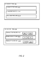
- FIG. 2 is a block diagram illustrating example architecture of a changeset table 142 and transaction table 146 used to maintain a changeset identifying changes made to the staging database 110 during the storing of the dataset 160 into the staging database 110 .
- the changeset table 142 includes a plurality of changeset records 144 -N
- the transaction table 146 includes a plurality of transaction records 148 -N.
- Each transaction record 148 - 1 contains a transaction identifier 152 - 1 and a transaction status 154 - 1 .
- FIG. 3 is a flowchart of the steps performed by the database synchronizing process 140 when it receives a dataset 160 for storing in a staging database 110 , the dataset 160 containing network management data collected from a managed resource.
- the database synchronizing process 140 receives a dataset 160 for storing in a staging database 110 .
- the dataset 160 contains network management data collected from a managed resource.
- the dataset 160 is transmitted by the agent 130 , and processed by a process on a store system 135 -N.
- multiple agents 130 -N are transmitting datasets 160 -N to the database synchronizing process 140 residing on the staging database 110 .
- step 201 the database synchronizing process 140 stores the dataset 160 in the staging database 110 .
- the dataset 160 is stored in the staging database 110 .
- the database synchronizing process 140 maintains a changeset identifying changes made to the staging database 110 during the step of storing the dataset 160 .
- the changeset is stored in a changeset table 142 containing changeset records 144 -N, and a transaction table 146 maintains changes in the changeset table 142 via a transaction identifier 152 -N and a transaction status 154 -N.
- the database synchronizing process 140 synchronizes the staging database 110 and the production database 120 with each other, using the changeset.
- the staging database 110 receives new data from the agent 130
- the staging database 110 utilizes the changeset table 142 and transaction table 146 to track the new changes in the staging database 110 .
- the staging database 110 then synchronizes with the production database 120 .
- the production database 120 receives new data from, for example, the server 180
- the production database 120 synchronizes with the staging database 110 .
- the production database 120 is locked (from receiving new data).
- FIG. 4 is a flowchart of the steps performed by the database synchronizing process 140 when it successfully stores the dataset 160 in the staging database 110 .
- step 204 the database synchronizing process 140 stores the dataset 160 in the staging database 110 .
- the dataset 160 is stored in the staging database 110 .
- the database synchronizing process 140 invokes transaction processing to begin a transaction of transmitting the dataset 160 at the staging database 110 .
- the transaction processing is a transaction software process that is invoked by the database synchronizing process 140 .
- the transaction processing process handles the transaction of receiving the dataset 160 at the staging database 110 .
- the transaction processing initializes a staging transaction table within the staging database 110 with parameters passed in via a transaction process function.
- the database synchronizing process 140 identifies that the dataset 160 is comprised of a plurality of partitions 170 -N.
- the dataset 160 is an extra large dataset 160 , for example, from a large storage system, such as a Symmetrix.
- the agent 130 divides the extra large dataset 160 into a plurality of partitions 170 -N for transmitting to the staging database 110 .
- the store system 135 - 1 processes each partition 170 - 1 in the order in which that partition 170 - 1 is received from the agent 130 , and transmits each partition 170 - 1 to the database synchronizing process 140 .
- Each partition 170 - 1 within the plurality of partitions 170 -N is treated as a separate database transaction during the storing of the plurality of partitions 170 -N (i.e., the dataset 160 ) in the staging database 110 .
- step 207 for each partition 170 - 1 within the plurality of partitions 170 -N, the database synchronizing process 140 performs the steps of:
- the partition processing is a partition software process that is invoked by the database synchronizing process 140 .
- the partition software process indicates the start of transmitting a partition 170 - 1 to the staging database 110 .
- Parameters passed into partition processing are used to execute a database procedure that saves a transaction identifier 152 -N into a staging session content session table.
- the commit partition processing is a commit partition software process that commits the partition 170 - 1 to the staging database 110 .
- the database synchronizes process 140 , invokes commit transaction processing to commit the transaction of receiving the dataset 160 at the staging database 110 .
- the commit transaction processing is a commit transaction software process.
- the commit transaction software process executes a stored procedure that copies staging data associated with a transaction identifier 152 -N (that is passed in as a parameter to the commit transaction software process) to the production database 120 . Once the data is successfully copied to the production database 120 , the commit transaction software process deletes corresponding data in the changeset table 142 .
- FIG. 5 is a flowchart of the steps performed by the database synchronizing process 140 when it unsuccessfully stores the dataset 160 in the staging database 110 .
- the database synchronizing process 140 invokes transaction processing to begin a transaction of transmitting the dataset 160 at the staging database 110 .
- the transaction processing is a transaction software process that is invoked by the database synchronizing process 140 .
- the transaction processing process handles the transaction of receiving the dataset 160 at the staging database 110 .
- the transaction processing initializes a staging transaction table within the staging database 110 with parameters passed in via a transaction process function.
- the database synchronizing process 140 identifies that the dataset 160 is comprised of a plurality of partitions 170 -N.
- the dataset 160 is an extra large dataset 160 , for example, from a large storage system, such as a Symmetrix.
- the agent 130 divides the extra large dataset 160 into a plurality of partitions 170 -N for transmitting to the staging database 110 .
- the store system 135 - 1 processes each partition 170 - 1 in the order in which that partition 170 - 1 is received from the agent 130 , and transmits each partition 170 - 1 to the database synchronizing process 140 .
- Each partition 170 - 1 within the plurality of partitions 170 -N is treated as a separate database transaction during the storing of the plurality of partitions 170 -N (i.e., the dataset 160 ) in the staging database 110 .
- step 210 the database synchronizing process 140 for each partition within the plurality of partitions, perform the steps of:
- the partition processing is a partition software process that is invoked by the database synchronizing process 140 .
- the partition software process indicates the start of transmitting a partition 170 - 1 to the staging database 110 .
- Parameters passed into partition processing are used to execute a database procedure that saves a transaction identifier 152 -N into a staging session content session table.
- An error can occur during the transmission of the partition to the staging database 110 , resulting in a partition 170 - 1 failing to be received at the staging database 110 .
- the abort partition processing is an abort partition software process that terminates the process of transmitting the partition 170 - 1 from the agent 130 to the staging database 110 .
- the database synchronizing process 140 invokes abort transaction processing to terminate the transaction processing of receiving the dataset 160 at the staging database 110 .
- the abort transaction processing is an abort transaction software process.
- the abort transaction software process executes a stored procedure that refreshes staging database 110 data modified by a transaction identifier 152 - 1 associated with the transaction.
- the abort transaction processing then removes data, associated with the aborted transaction, from the changeset table 142 and transaction table 146 . In other words, the data in the staging database 110 (associated with the aborted transaction) is rolled back.
- FIG. 6 is a flowchart of the steps performed by the database synchronizing process 140 when it stores the dataset 160 in the staging database 110 .
- the database synchronizing process 140 stores the dataset 160 in the staging database 110 .
- the dataset 160 is stored in the staging database 110 .
- the database synchronizing process 140 stores a data record, from the dataset 160 , in at least one staging table from the plurality of staging tables.
- the staging database 110 contains a plurality of staging tables.
- the plurality of staging tables in the staging corresponds to the tables in the production database 120 that will be modified by the insertion of the dataset 160 into the production database 120 .
- the database synchronizing process 140 stores each data record from the dataset 160 (received from the agent 130 ) in the appropriate staging tables.
- the database synchronizing process 140 records at least one changeset record 144 - 1 in a changeset table 142 .
- the changeset record 144 - 1 is associated with the data record stored in the staging tables of step 213 .
- the changeset table 142 tracks changes made to the staging tables in the staging database 110 . As each data record from the dataset 160 is inserted into staging tables, a corresponding changeset record 144 - 1 is inserted into the changeset table 142 .
- step 215 for each staging table in the plurality of staging tables where a data record has been stored, the database synchronizing process 140 invokes a changeset processing that begins the process of recording the changeset record 144 - 1 in the changeset table 142 .
- the changeset processing is a trigger that is invoked on the staging database 110 .
- Each staging table has associated changeset trigger that records the changeset record 144 - 1 in the changeset table 142 .
- the database synchronizing process 140 records a transaction record 148 - 1 in a transaction table 146 .
- the transaction record 148 - 1 is associated with a corresponding changeset record 144 - 1 in the changeset table 142 .
- the transaction table 146 tracks the status of the changeset record 144 - 1 in the changeset table 142 .
- step 217 for each of the changeset records 144 - 1 recorded in the changeset table 142 , the database synchronizing process 140 invokes transaction record processing (for example, a transaction record software process, trigger, etc) that begins the process of recording the transaction record 148 - 1 in the transaction table 146 .
- the transaction record 148 - 1 includes a transaction identifier 152 - 1 identifying the changeset record 144 - 1 , and a transaction status 154 - 1 that indicates the process of storing the dataset 160 in the staging database 110 is in progress.
- FIG. 7 is a flowchart of the steps performed by the database synchronizing process 140 when it synchronizes the staging database 110 and the production database 120 with each other.
- the database synchronizing process 140 synchronizes the staging database 110 and the production database 120 with each other using the changeset (i.e., the changeset table 142 and the transaction table 146 ).
- the staging database 110 receives new data from the agent 130
- the staging database 110 utilizes the changeset table 142 and transaction table 146 to track the new changes in the staging database 110 .
- the staging database 110 then synchronizes with the production database 120 .
- the production database 120 receives new data from, for example, the server 180
- the production database 120 synchronizes with the staging database 110 .
- the production database 120 is locked (from receiving new data).
- the database synchronizing process 140 identifies a hierarchy among the plurality of staging tables within the staging database 110 .
- the hierarchy is defined by relationships between managed resources in a storage area network from which the dataset 160 is collected. For example, hosts in a storage area network have adapters and databases, thus the host maintains a higher position in the hierarchy than the adapters or databases.
- the database synchronizing process 140 identifies a primary key in a first staging table within the plurality of staging tables.
- a primary key is a key in a relational database table that uniquely defines each record in that database table.
- the serial number of the Symmetrix system could be a unique identifier for a record in a table associated with Symmetrix systems.
- the database synchronizing process 140 identifies the primary key in the first staging table is a foreign key in a second staging table.
- a foreign key is a field in a relational database table that matches a primary key in another relational database table.
- Foreign keys can be used to create relationships between tables in a relational database.
- a database table has a unique key (i.e., a primary key) that uniquely identifies every database contained within the database table.
- the databases in the database table may physically reside on a Symmetrix system.
- the primary key of the database table could be a field in the Symmetrix table identifying those databases that reside on a particular Symmetrix system.
- the database synchronizing process 140 based on a relationship of the primary key and the foreign key, identifies that a second staging table maintains a higher position than the first staging table within the hierarchy among the plurality of staging tables.
- a primary key of a database table may be a foreign key in a Symmetrix table. Therefore, the database synchronizing process 140 identifies that the Symmetrix table maintains a higher position in the hierarchy than the database table.
- the database synchronizing process 140 identifies a sequential order in which to synchronize the dataset 160 from the staging database 110 to the production database 120 based on the hierarchy. As there exists a parent child relationship between tables in a database, there is a proper order in which to add, delete and/or modify data within a relational database.
- the agent 130 provides the database synchronizing process 140 with the sequential order in which to synchronize the dataset 160 from the staging database 110 to the production database 120 .
- step 224 the database synchronizing process 140 copies the dataset 160 from the staging database 110 to the production database 120 , according to the sequential order provided by the agent 130 .
- FIG. 8 is a flowchart of a continuation of the steps performed by the database synchronizing process 140 when it copies the dataset 160 from the staging database 110 to the production database 120 according to the sequential order.
- step 224 the database synchronizing process 140 copies the dataset 160 from the staging database 110 to the production database 120 , according to the sequential order provided by the agent 130 .
- the database synchronizing process 140 identifies, in the dataset 160 , a data record to be deleted from the second staging table in the production database 120 .
- a changeset is maintained of those changes made to the staging database 110 .
- the changeset is utilized to synchronize the production database 120 with the staging database 110 .
- a data record was deleted from the staging database 110 and the changeset indicates that a data record is to be deleted from a second staging table in the production database 120 .
- the database synchronizing process 140 deletes the data record from the first staging table in the production database 120 .
- the database synchronizing process 140 identifies a hierarchy between the first staging table and a second staging table in the production database 120 whereby the first staging table is a child of the second staging table.
- the database synchronizing process 140 first deletes the data record from the first staging table in the production database 120 .
- step 227 following the deletion of the data record from the first staging table in the production database 120 , the database synchronizing process 140 deletes the data record in the second staging table in the production database.
- the database synchronizing process 140 first deletes the data record in the first staging table (i.e., the ‘child’) in the production database 120 prior to deleting the data record in the second staging table (i.e., the ‘parent’). If the second staging table were deleted prior to the first staging table, the parent child relationship between the first staging table and the second staging table would be severed, causing difficulty in maintaining the relational database.
- the database synchronizing process 140 identifies, in the dataset 160 , a data record to be inserted into the first staging table in the production database 120 .
- a changeset is maintained of those changes made to the staging database 110 .
- the changeset is utilized to synchronize the production database 120 with the staging database 110 .
- a data record was inserted into the staging database 110 and the changeset indicates that a data record is to be inserted into a second staging table in the production database 120 .
- the database synchronizing process 140 inserts the data record in the second staging table in the production database 120 .
- the database synchronizing process 140 identifies a hierarchy between the first staging table and a second staging table in the production database 120 whereby the first staging table is a parent of the second staging table.
- the database synchronizing process 140 first inserts the data record into the first staging table in the production database 120 (i.e., the “parent”).
- step 230 following the insertion of the data record in the first staging table in the production database 120 , the database synchronizing process 140 inserts the data record in the second staging table in the production database 120 (i.e., the “child”). To maintain the proper hierarchy, the database synchronizing process 140 first inserts the data record into the first staging table in the production database 120 prior to inserting the data record into the second staging table. If the data record were inserted into the second staging table to the first staging table, it would be difficult to establish the primary key for the first staging table (i.e., the parent table), and maintain the proper hierarchy.
- the database synchronizing process 140 inserts the data record in the second staging table in the production database 120 (i.e., the “child”). To maintain the proper hierarchy, the database synchronizing process 140 first inserts the data record into the first staging table in the production database 120 prior to inserting the data record into the second staging table. If the data record were inserted into the second staging table to the first staging table, it would be difficult to establish the primary key for the first staging table (
- FIG. 9 is a flowchart of a continuation of the steps performed by the database synchronizing process 140 when it identifies a hierarchy among the plurality of staging tables.
- the database synchronizing process 140 identifies a hierarchy among the plurality of staging tables within the staging database 110 .
- the hierarchy is defined by relationships between managed resources in a storage area network from which the dataset 160 is collected. For example, hosts in a storage area network have adapters and databases, thus the host is maintains a higher position in the hierarchy than the adapters or databases.
- the database synchronizing process 140 identifies a self-referencing relationship between staging tables.
- An example of a self-referencing relationship between tables is a first table having a primary key that is a foreign key of a second table, and the second table having a primary key that is a foreign key in a first staging table.
- step 233 the database synchronizing process 140 identifies a primary key in the first staging table is a foreign key in the second staging table.
- step 234 the database synchronizing process 140 identifies a primary key in the second staging table is a foreign key in the first staging table.
- FIG. 10 is a flowchart of a continuation of the steps performed by the database synchronizing process 140 when copies the dataset 160 from the staging database 110 to the production database 120 , according to the sequential order.
- step 235 the database synchronizing process 140 copies the dataset 160 from the staging database 110 to the production database 120 , according to the sequential order provided by the agent 130 .
- the database synchronizing process 140 identifies, in the dataset 160 , a data record to be updated in the first staging table in the production database 120 .
- the database synchronizing process 140 identifies a self-referencing relationship between the first staging table and a second staging table.
- step 237 the database synchronizing process 140 nullifies the foreign key in the second staging table.
- the foreign key in the second staging table is set to null.
- step 238 the database synchronizing process 140 nullifies the foreign key in the staging table.
- the foreign key in the first staging table is set to null.
- step 239 the database synchronizing process 140 updates the data record in the first staging table in the production database 120 .
- the data record was updated.
- the corresponding data record in the production database 120 is updated.
- step 240 following the updating of the data record in the first staging table in the production database 120 , the database synchronizing process 140 , sets the foreign key in the second staging table to the primary key in the first staging table.
- the database synchronizing process 140 resets the nullified foreign key, in the second staging table, to point to the primary key in the first staging table.
- step 241 the database synchronizing process 140 sets the foreign key in the first staging table to a primary key in the second staging table.
- the database synchronizing process 140 resets the nullified foreign key, in the first staging table, to point to the primary key in the second staging table.
- FIG. 11 is a flowchart of the steps performed by the database synchronizing process 140 when synchronizes the staging database 110 and the production database 120 with each other using the changeset.
- the database synchronizing process 140 synchronizes the staging database 110 and the production database 120 with each other using the changeset (i.e., the changeset table 142 and the transaction table 146 ).
- the staging database 110 receives new data from the agent 130
- the staging database 110 utilizes the changeset table 142 and transaction table 146 to track the new changes in the staging database 110 .
- the staging database 110 then synchronizes with the production database 120 .
- the production database 120 receives new data from, for example, the server 180
- the production database 120 synchronizes with the staging database 110 .
- the production database 120 is locked (from receiving new data).
- step 243 the database synchronizing process 140 invokes changeset table processing that identifies at least one transaction status 154 - 1 associated with at least one transaction record 148 - 1 in a transaction table 146 .
- the transaction record 148 - 1 is associated with a data record copied from the staging database 110 to the production database 120 .
- the transaction status 154 - 1 indicates that the process of storing the data record in the production database 120 is in progress.
- the database synchronizing process 140 deletes at least one changeset record 144 - 1 in a changeset table 142 .
- the changeset record 144 - 1 contains a transaction identifier 152 - 1 , a table record identifier identifying a data record in the table in the production database 120 in which the data record was copied, a table identifier identifying the table in the production database 120 in which the data record was copied, and an action associated with the data record in the table in the production database 120 , such as whether the data record was inserted, deleted and/or updated.
- the changeset record 144 - 1 is associated with the transaction record 148 - 1 having a transaction status 154 - 1 . When the data record is inserted into the staging database 110 , the transaction status 154 - 1 is set to “in progress”.
- step 245 once the data record has been copied from the staging database 110 to the production database 120 , the database synchronizing process 140 modifies the transaction status 154 - 1 to include at least one of:
- step 246 the database synchronizing process 140 invokes transaction table processing that deletes the transaction record 148 - 1 having the transaction status 154 - 1 .
- a transaction table software process runs periodically, and deletes all the transaction records 148 -N in the transaction table 146 that have a transaction status 154 - 1 of either ‘success’ or ‘error’.
Abstract
Description
Claims (19)
Priority Applications (1)
| Application Number | Priority Date | Filing Date | Title |
|---|---|---|---|
| US11/477,026 US7689565B1 (en) | 2006-06-28 | 2006-06-28 | Methods and apparatus for synchronizing network management data |
Applications Claiming Priority (1)
| Application Number | Priority Date | Filing Date | Title |
|---|---|---|---|
| US11/477,026 US7689565B1 (en) | 2006-06-28 | 2006-06-28 | Methods and apparatus for synchronizing network management data |
Publications (1)
| Publication Number | Publication Date |
|---|---|
| US7689565B1 true US7689565B1 (en) | 2010-03-30 |
Family
ID=42044674
Family Applications (1)
| Application Number | Title | Priority Date | Filing Date |
|---|---|---|---|
| US11/477,026 Active 2027-03-19 US7689565B1 (en) | 2006-06-28 | 2006-06-28 | Methods and apparatus for synchronizing network management data |
Country Status (1)
| Country | Link |
|---|---|
| US (1) | US7689565B1 (en) |
Cited By (18)
| Publication number | Priority date | Publication date | Assignee | Title |
|---|---|---|---|---|
| US20080222209A1 (en) * | 2007-03-09 | 2008-09-11 | Fujitsu Limited | Database management method and database management apparatus |
| US20090187917A1 (en) * | 2008-01-17 | 2009-07-23 | International Business Machines Corporation | Transfer of data from transactional data sources to partitioned databases in restartable environments |
| US20090187787A1 (en) * | 2008-01-17 | 2009-07-23 | International Business Machines Corporation | Transfer of data from positional data sources to partitioned databases in restartable environments |
| US20100042638A1 (en) * | 2006-12-06 | 2010-02-18 | Jianxiu Hao | Apparatus, method, and computer program product for synchronizing data sources |
| US20110078200A1 (en) * | 2009-09-30 | 2011-03-31 | Eric Williamson | Systems and methods for conditioning the distribution of data in a hierarchical database |
| CN102306189A (en) * | 2011-08-31 | 2012-01-04 | 珠海金山办公软件有限公司 | Client and method for client to show status of network disk file |
| US20120185449A1 (en) * | 2011-01-14 | 2012-07-19 | Ab Initio Technology Llc | Managing changes to collections of data |
| WO2014031340A3 (en) * | 2012-08-20 | 2014-05-01 | Sears Brands, Llc | Methods and systems for staging and propagating data |
| US20140149368A1 (en) * | 2012-11-28 | 2014-05-29 | Juchang Lee | Compressed Representation of a Transaction Token |
| US8996453B2 (en) | 2009-09-30 | 2015-03-31 | Red Hat, Inc. | Distribution of data in a lattice-based database via placeholder nodes |
| US9031987B2 (en) | 2009-09-30 | 2015-05-12 | Red Hat, Inc. | Propagation of data changes in distribution operations in hierarchical database |
| US9626393B2 (en) | 2014-09-10 | 2017-04-18 | Ab Initio Technology Llc | Conditional validation rules |
| US9977659B2 (en) | 2010-10-25 | 2018-05-22 | Ab Initio Technology Llc | Managing data set objects |
| US10175974B2 (en) | 2014-07-18 | 2019-01-08 | Ab Initio Technology Llc | Managing lineage information |
| US10489360B2 (en) | 2012-10-17 | 2019-11-26 | Ab Initio Technology Llc | Specifying and applying rules to data |
| US20210149870A1 (en) * | 2017-05-17 | 2021-05-20 | HealthStream, Inc. | Method, apparatus, and computer program product for improved tracking of state data |
| US20210365439A1 (en) * | 2020-05-22 | 2021-11-25 | Couchbase, Inc. | Distributed transaction execution in distributed databases |
| US11341155B2 (en) | 2008-12-02 | 2022-05-24 | Ab Initio Technology Llc | Mapping instances of a dataset within a data management system |
Citations (9)
| Publication number | Priority date | Publication date | Assignee | Title |
|---|---|---|---|---|
| US5761500A (en) * | 1996-04-18 | 1998-06-02 | Mci Communications Corp. | Multi-site data communications network database partitioned by network elements |
| US6122630A (en) * | 1999-06-08 | 2000-09-19 | Iti, Inc. | Bidirectional database replication scheme for controlling ping-ponging |
| US20020095408A1 (en) * | 2000-11-24 | 2002-07-18 | Qi Cheng | Method and apparatus for deleting data in a database |
| US6502092B1 (en) * | 2000-08-01 | 2002-12-31 | Bmc Software, Inc. | Referential integrity navigation in a database system |
| US20030133452A1 (en) * | 2002-01-16 | 2003-07-17 | Winbond Electronics Corp. | Multi channels data transmission control method |
| US6691166B1 (en) * | 1999-01-07 | 2004-02-10 | Sun Microsystems, Inc. | System and method for transferring partitioned data sets over multiple threads |
| US20040068501A1 (en) * | 2002-10-03 | 2004-04-08 | Mcgoveran David O. | Adaptive transaction manager for complex transactions and business process |
| US20040088432A1 (en) * | 2002-10-31 | 2004-05-06 | Hubbard Eric D. | Management of attribute data |
| US20050165817A1 (en) * | 2004-01-08 | 2005-07-28 | O'conor George W. | Data migration and analysis |
-
2006
- 2006-06-28 US US11/477,026 patent/US7689565B1/en active Active
Patent Citations (9)
| Publication number | Priority date | Publication date | Assignee | Title |
|---|---|---|---|---|
| US5761500A (en) * | 1996-04-18 | 1998-06-02 | Mci Communications Corp. | Multi-site data communications network database partitioned by network elements |
| US6691166B1 (en) * | 1999-01-07 | 2004-02-10 | Sun Microsystems, Inc. | System and method for transferring partitioned data sets over multiple threads |
| US6122630A (en) * | 1999-06-08 | 2000-09-19 | Iti, Inc. | Bidirectional database replication scheme for controlling ping-ponging |
| US6502092B1 (en) * | 2000-08-01 | 2002-12-31 | Bmc Software, Inc. | Referential integrity navigation in a database system |
| US20020095408A1 (en) * | 2000-11-24 | 2002-07-18 | Qi Cheng | Method and apparatus for deleting data in a database |
| US20030133452A1 (en) * | 2002-01-16 | 2003-07-17 | Winbond Electronics Corp. | Multi channels data transmission control method |
| US20040068501A1 (en) * | 2002-10-03 | 2004-04-08 | Mcgoveran David O. | Adaptive transaction manager for complex transactions and business process |
| US20040088432A1 (en) * | 2002-10-31 | 2004-05-06 | Hubbard Eric D. | Management of attribute data |
| US20050165817A1 (en) * | 2004-01-08 | 2005-07-28 | O'conor George W. | Data migration and analysis |
Non-Patent Citations (12)
| Title |
|---|
| FFE Software, Inc., "Extended Referential Integrity." FirstSQL.com. 1998. May 18, 2008 . * |
| FFE Software, Inc., "Extended Referential Integrity." FirstSQL.com. 1998. May 18, 2008 <http://www.firstsql.com/ixrefer.htm>. * |
| Gilfillan, Ian. "Referential Integrity in MySQL." Database Journal. Aug. 19, 2003 May 16, 2008 . * |
| Gilfillan, Ian. "Referential Integrity in MySQL." Database Journal. Aug. 19, 2003 May 16, 2008 <http://www.databasejournal.com/features/mysql/article.php/10897—2248101—1>. * |
| IBM TDB, "Recovery Protocol Using a Common Log" IBM Technical Disclosure Bulletin 24(1982): 6211-6212. * |
| IBM WebSphere Commerce 5.6.1.4 Help, "Testing the site on a staging server" (2005) http://publib.boulder.ibm.com/infocenter/wchelp/v5r6m1/index.jsp?topic=/com.ibm.commerce.admin.doc/tasks/tsstest.htm. * |
| IBM, John Ganci et al. "WebSphere Commerce V5.4 Catalog Design and Content Management", IBM RedBook (2003) May 14, 2008 . * |
| IBM, John Ganci et al. "WebSphere Commerce V5.4 Catalog Design and Content Management", IBM RedBook (2003) May 14, 2008 <http://www.redbooks.ibm.com/abstracts/SG246855.html>. * |
| Sybase, "System Administration Guide (Online Only)." Sybase Technical Library Product Manuals (2003) May 19, 2008 <http://web.archive.org/web/20030422213757/http://manuals.sybase.com/onlinebooks/group-as/asg1250e/sag/@Generic-BookTextView/60150>. * |
| Sybase, "System Administration Guide (Online Only)." Sybase Technical Library Product Manuals (2003) May 19, 2008 <http://web.archive.org/web/20030422213757/http://manuals.sybase.com/onlinebooks/group-as/asg1250e/sag/@Generic—BookTextView/60150>. * |
| Worsley, John and Joshua Drake. Practical PostgreSQL. O'Reilly Media, Inc., 2002. . * |
| Worsley, John and Joshua Drake. Practical PostgreSQL. O'Reilly Media, Inc., 2002. <http://chestofbooks.com/computers/databases/postgresql/practical-postgresql/Inheritance.html>. * |
Cited By (29)
| Publication number | Priority date | Publication date | Assignee | Title |
|---|---|---|---|---|
| US8280847B2 (en) * | 2006-12-06 | 2012-10-02 | Verizon Patent And Licensing Inc. | Apparatus, method, and computer program product for synchronizing data sources |
| US20100042638A1 (en) * | 2006-12-06 | 2010-02-18 | Jianxiu Hao | Apparatus, method, and computer program product for synchronizing data sources |
| US7908245B2 (en) * | 2007-03-09 | 2011-03-15 | Fujitsu Limited | Database management method and database management apparatus |
| US20080222209A1 (en) * | 2007-03-09 | 2008-09-11 | Fujitsu Limited | Database management method and database management apparatus |
| US20090187917A1 (en) * | 2008-01-17 | 2009-07-23 | International Business Machines Corporation | Transfer of data from transactional data sources to partitioned databases in restartable environments |
| US20090187787A1 (en) * | 2008-01-17 | 2009-07-23 | International Business Machines Corporation | Transfer of data from positional data sources to partitioned databases in restartable environments |
| US8156084B2 (en) * | 2008-01-17 | 2012-04-10 | International Business Machines Corporation | Transfer of data from positional data sources to partitioned databases in restartable environments |
| US8521682B2 (en) | 2008-01-17 | 2013-08-27 | International Business Machines Corporation | Transfer of data from transactional data sources to partitioned databases in restartable environments |
| US11341155B2 (en) | 2008-12-02 | 2022-05-24 | Ab Initio Technology Llc | Mapping instances of a dataset within a data management system |
| US8996453B2 (en) | 2009-09-30 | 2015-03-31 | Red Hat, Inc. | Distribution of data in a lattice-based database via placeholder nodes |
| US8984013B2 (en) * | 2009-09-30 | 2015-03-17 | Red Hat, Inc. | Conditioning the distribution of data in a hierarchical database |
| US9031987B2 (en) | 2009-09-30 | 2015-05-12 | Red Hat, Inc. | Propagation of data changes in distribution operations in hierarchical database |
| US20110078200A1 (en) * | 2009-09-30 | 2011-03-31 | Eric Williamson | Systems and methods for conditioning the distribution of data in a hierarchical database |
| US9977659B2 (en) | 2010-10-25 | 2018-05-22 | Ab Initio Technology Llc | Managing data set objects |
| US9418095B2 (en) * | 2011-01-14 | 2016-08-16 | Ab Initio Technology Llc | Managing changes to collections of data |
| US20120185449A1 (en) * | 2011-01-14 | 2012-07-19 | Ab Initio Technology Llc | Managing changes to collections of data |
| CN102306189A (en) * | 2011-08-31 | 2012-01-04 | 珠海金山办公软件有限公司 | Client and method for client to show status of network disk file |
| US9058367B2 (en) * | 2012-08-20 | 2015-06-16 | Sears Brands, L.L.C. | Methods and systems for staging and propagating data |
| EP3564827A1 (en) * | 2012-08-20 | 2019-11-06 | Sears Brands, LLC | Methods and systems for staging and propagating data |
| WO2014031340A3 (en) * | 2012-08-20 | 2014-05-01 | Sears Brands, Llc | Methods and systems for staging and propagating data |
| US10489360B2 (en) | 2012-10-17 | 2019-11-26 | Ab Initio Technology Llc | Specifying and applying rules to data |
| US9805074B2 (en) * | 2012-11-28 | 2017-10-31 | Sap Ag | Compressed representation of a transaction token |
| US20140149368A1 (en) * | 2012-11-28 | 2014-05-29 | Juchang Lee | Compressed Representation of a Transaction Token |
| US10318283B2 (en) | 2014-07-18 | 2019-06-11 | Ab Initio Technology Llc | Managing parameter sets |
| US10175974B2 (en) | 2014-07-18 | 2019-01-08 | Ab Initio Technology Llc | Managing lineage information |
| US11210086B2 (en) | 2014-07-18 | 2021-12-28 | Ab Initio Technology Llc | Managing parameter sets |
| US9626393B2 (en) | 2014-09-10 | 2017-04-18 | Ab Initio Technology Llc | Conditional validation rules |
| US20210149870A1 (en) * | 2017-05-17 | 2021-05-20 | HealthStream, Inc. | Method, apparatus, and computer program product for improved tracking of state data |
| US20210365439A1 (en) * | 2020-05-22 | 2021-11-25 | Couchbase, Inc. | Distributed transaction execution in distributed databases |
Similar Documents
| Publication | Publication Date | Title |
|---|---|---|
| US7689565B1 (en) | Methods and apparatus for synchronizing network management data | |
| US7478099B1 (en) | Methods and apparatus for collecting database transactions | |
| US9684566B2 (en) | Techniques for backup restore and recovery of a pluggable database | |
| US7672979B1 (en) | Backup and restore techniques using inconsistent state indicators | |
| EP1618475B1 (en) | Flashback database | |
| US6857053B2 (en) | Method, system, and program for backing up objects by creating groups of objects | |
| US7792800B1 (en) | Data repository upgrade process | |
| US20160259574A1 (en) | Incremental replication of a source data set | |
| US7257690B1 (en) | Log-structured temporal shadow store | |
| US7610314B2 (en) | Online tablespace recovery for export | |
| US7801846B2 (en) | Generating log sequence identifiers to apply a transaction to a storage system | |
| US8756196B2 (en) | Propagating tables while preserving cyclic foreign key relationships | |
| US20030220935A1 (en) | Method of logical database snapshot for log-based replication | |
| US20070198599A1 (en) | Distributed conflict resolution for replicated databases | |
| US7680831B1 (en) | Methods and apparatus for detection and recovery of database out of synchronization conditions | |
| US7720884B1 (en) | Automatic generation of routines and/or schemas for database management | |
| US20060294421A1 (en) | Isolating and storing configuration data for disaster recovery | |
| US8015155B2 (en) | Non-disruptive backup copy in a database online reorganization environment | |
| US20070198690A1 (en) | Data Management System | |
| US20060294420A1 (en) | Isolating and storing configuration data for disaster recovery | |
| US8024171B1 (en) | Managed resource simulator for storage area networks | |
| KR20060007435A (en) | Managing a relationship between one target volume and one source volume | |
| US7689587B1 (en) | Autorep process to create repository according to seed data and at least one new schema | |
| CN115220941A (en) | Rollback recovery for data pipes using data lineage capture | |
| US8103685B1 (en) | Methods and apparatus for capturing last discovery time of managed objects |
Legal Events
| Date | Code | Title | Description |
|---|---|---|---|
| AS | Assignment |
Owner name: EMC CORPORATION,MASSACHUSETTS Free format text: ASSIGNMENT OF ASSIGNORS INTEREST;ASSIGNORS:GANDHI, RAJESH K.;CARSON, JR., KEITH ALAN;TIRUVEEDI, VENKATA R.;REEL/FRAME:018022/0829 Effective date: 20060626 |
|
| STCF | Information on status: patent grant |
Free format text: PATENTED CASE |
|
| FPAY | Fee payment |
Year of fee payment: 4 |
|
| AS | Assignment |
Owner name: CREDIT SUISSE AG, CAYMAN ISLANDS BRANCH, AS COLLATERAL AGENT, NORTH CAROLINA Free format text: SECURITY AGREEMENT;ASSIGNORS:ASAP SOFTWARE EXPRESS, INC.;AVENTAIL LLC;CREDANT TECHNOLOGIES, INC.;AND OTHERS;REEL/FRAME:040134/0001 Effective date: 20160907 Owner name: THE BANK OF NEW YORK MELLON TRUST COMPANY, N.A., AS NOTES COLLATERAL AGENT, TEXAS Free format text: SECURITY AGREEMENT;ASSIGNORS:ASAP SOFTWARE EXPRESS, INC.;AVENTAIL LLC;CREDANT TECHNOLOGIES, INC.;AND OTHERS;REEL/FRAME:040136/0001 Effective date: 20160907 Owner name: CREDIT SUISSE AG, CAYMAN ISLANDS BRANCH, AS COLLAT Free format text: SECURITY AGREEMENT;ASSIGNORS:ASAP SOFTWARE EXPRESS, INC.;AVENTAIL LLC;CREDANT TECHNOLOGIES, INC.;AND OTHERS;REEL/FRAME:040134/0001 Effective date: 20160907 Owner name: THE BANK OF NEW YORK MELLON TRUST COMPANY, N.A., A Free format text: SECURITY AGREEMENT;ASSIGNORS:ASAP SOFTWARE EXPRESS, INC.;AVENTAIL LLC;CREDANT TECHNOLOGIES, INC.;AND OTHERS;REEL/FRAME:040136/0001 Effective date: 20160907 |
|
| AS | Assignment |
Owner name: EMC IP HOLDING COMPANY LLC, MASSACHUSETTS Free format text: ASSIGNMENT OF ASSIGNORS INTEREST;ASSIGNOR:EMC CORPORATION;REEL/FRAME:040203/0001 Effective date: 20160906 |
|
| MAFP | Maintenance fee payment |
Free format text: PAYMENT OF MAINTENANCE FEE, 8TH YEAR, LARGE ENTITY (ORIGINAL EVENT CODE: M1552) Year of fee payment: 8 |
|
| AS | Assignment |
Owner name: THE BANK OF NEW YORK MELLON TRUST COMPANY, N.A., T Free format text: SECURITY AGREEMENT;ASSIGNORS:CREDANT TECHNOLOGIES, INC.;DELL INTERNATIONAL L.L.C.;DELL MARKETING L.P.;AND OTHERS;REEL/FRAME:049452/0223 Effective date: 20190320 Owner name: THE BANK OF NEW YORK MELLON TRUST COMPANY, N.A., TEXAS Free format text: SECURITY AGREEMENT;ASSIGNORS:CREDANT TECHNOLOGIES, INC.;DELL INTERNATIONAL L.L.C.;DELL MARKETING L.P.;AND OTHERS;REEL/FRAME:049452/0223 Effective date: 20190320 |
|
| AS | Assignment |
Owner name: THE BANK OF NEW YORK MELLON TRUST COMPANY, N.A., TEXAS Free format text: SECURITY AGREEMENT;ASSIGNORS:CREDANT TECHNOLOGIES INC.;DELL INTERNATIONAL L.L.C.;DELL MARKETING L.P.;AND OTHERS;REEL/FRAME:053546/0001 Effective date: 20200409 |
|
| MAFP | Maintenance fee payment |
Free format text: PAYMENT OF MAINTENANCE FEE, 12TH YEAR, LARGE ENTITY (ORIGINAL EVENT CODE: M1553); ENTITY STATUS OF PATENT OWNER: LARGE ENTITY Year of fee payment: 12 |
|
| AS | Assignment |
Owner name: WYSE TECHNOLOGY L.L.C., CALIFORNIA Free format text: RELEASE BY SECURED PARTY;ASSIGNOR:CREDIT SUISSE AG, CAYMAN ISLANDS BRANCH;REEL/FRAME:058216/0001 Effective date: 20211101 Owner name: SCALEIO LLC, MASSACHUSETTS Free format text: RELEASE BY SECURED PARTY;ASSIGNOR:CREDIT SUISSE AG, CAYMAN ISLANDS BRANCH;REEL/FRAME:058216/0001 Effective date: 20211101 Owner name: MOZY, INC., WASHINGTON Free format text: RELEASE BY SECURED PARTY;ASSIGNOR:CREDIT SUISSE AG, CAYMAN ISLANDS BRANCH;REEL/FRAME:058216/0001 Effective date: 20211101 Owner name: MAGINATICS LLC, CALIFORNIA Free format text: RELEASE BY SECURED PARTY;ASSIGNOR:CREDIT SUISSE AG, CAYMAN ISLANDS BRANCH;REEL/FRAME:058216/0001 Effective date: 20211101 Owner name: FORCE10 NETWORKS, INC., CALIFORNIA Free format text: RELEASE BY SECURED PARTY;ASSIGNOR:CREDIT SUISSE AG, CAYMAN ISLANDS BRANCH;REEL/FRAME:058216/0001 Effective date: 20211101 Owner name: EMC IP HOLDING COMPANY LLC, TEXAS Free format text: RELEASE BY SECURED PARTY;ASSIGNOR:CREDIT SUISSE AG, CAYMAN ISLANDS BRANCH;REEL/FRAME:058216/0001 Effective date: 20211101 Owner name: EMC CORPORATION, MASSACHUSETTS Free format text: RELEASE BY SECURED PARTY;ASSIGNOR:CREDIT SUISSE AG, CAYMAN ISLANDS BRANCH;REEL/FRAME:058216/0001 Effective date: 20211101 Owner name: DELL SYSTEMS CORPORATION, TEXAS Free format text: RELEASE BY SECURED PARTY;ASSIGNOR:CREDIT SUISSE AG, CAYMAN ISLANDS BRANCH;REEL/FRAME:058216/0001 Effective date: 20211101 Owner name: DELL SOFTWARE INC., CALIFORNIA Free format text: RELEASE BY SECURED PARTY;ASSIGNOR:CREDIT SUISSE AG, CAYMAN ISLANDS BRANCH;REEL/FRAME:058216/0001 Effective date: 20211101 Owner name: DELL PRODUCTS L.P., TEXAS Free format text: RELEASE BY SECURED PARTY;ASSIGNOR:CREDIT SUISSE AG, CAYMAN ISLANDS BRANCH;REEL/FRAME:058216/0001 Effective date: 20211101 Owner name: DELL MARKETING L.P., TEXAS Free format text: RELEASE BY SECURED PARTY;ASSIGNOR:CREDIT SUISSE AG, CAYMAN ISLANDS BRANCH;REEL/FRAME:058216/0001 Effective date: 20211101 Owner name: DELL INTERNATIONAL, L.L.C., TEXAS Free format text: RELEASE BY SECURED PARTY;ASSIGNOR:CREDIT SUISSE AG, CAYMAN ISLANDS BRANCH;REEL/FRAME:058216/0001 Effective date: 20211101 Owner name: DELL USA L.P., TEXAS Free format text: RELEASE BY SECURED PARTY;ASSIGNOR:CREDIT SUISSE AG, CAYMAN ISLANDS BRANCH;REEL/FRAME:058216/0001 Effective date: 20211101 Owner name: CREDANT TECHNOLOGIES, INC., TEXAS Free format text: RELEASE BY SECURED PARTY;ASSIGNOR:CREDIT SUISSE AG, CAYMAN ISLANDS BRANCH;REEL/FRAME:058216/0001 Effective date: 20211101 Owner name: AVENTAIL LLC, CALIFORNIA Free format text: RELEASE BY SECURED PARTY;ASSIGNOR:CREDIT SUISSE AG, CAYMAN ISLANDS BRANCH;REEL/FRAME:058216/0001 Effective date: 20211101 Owner name: ASAP SOFTWARE EXPRESS, INC., ILLINOIS Free format text: RELEASE BY SECURED PARTY;ASSIGNOR:CREDIT SUISSE AG, CAYMAN ISLANDS BRANCH;REEL/FRAME:058216/0001 Effective date: 20211101 |
|
| AS | Assignment |
Owner name: SCALEIO LLC, MASSACHUSETTS Free format text: RELEASE OF SECURITY INTEREST IN PATENTS PREVIOUSLY RECORDED AT REEL/FRAME (040136/0001);ASSIGNOR:THE BANK OF NEW YORK MELLON TRUST COMPANY, N.A., AS NOTES COLLATERAL AGENT;REEL/FRAME:061324/0001 Effective date: 20220329 Owner name: EMC IP HOLDING COMPANY LLC (ON BEHALF OF ITSELF AND AS SUCCESSOR-IN-INTEREST TO MOZY, INC.), TEXAS Free format text: RELEASE OF SECURITY INTEREST IN PATENTS PREVIOUSLY RECORDED AT REEL/FRAME (040136/0001);ASSIGNOR:THE BANK OF NEW YORK MELLON TRUST COMPANY, N.A., AS NOTES COLLATERAL AGENT;REEL/FRAME:061324/0001 Effective date: 20220329 Owner name: EMC CORPORATION (ON BEHALF OF ITSELF AND AS SUCCESSOR-IN-INTEREST TO MAGINATICS LLC), MASSACHUSETTS Free format text: RELEASE OF SECURITY INTEREST IN PATENTS PREVIOUSLY RECORDED AT REEL/FRAME (040136/0001);ASSIGNOR:THE BANK OF NEW YORK MELLON TRUST COMPANY, N.A., AS NOTES COLLATERAL AGENT;REEL/FRAME:061324/0001 Effective date: 20220329 Owner name: DELL MARKETING CORPORATION (SUCCESSOR-IN-INTEREST TO FORCE10 NETWORKS, INC. AND WYSE TECHNOLOGY L.L.C.), TEXAS Free format text: RELEASE OF SECURITY INTEREST IN PATENTS PREVIOUSLY RECORDED AT REEL/FRAME (040136/0001);ASSIGNOR:THE BANK OF NEW YORK MELLON TRUST COMPANY, N.A., AS NOTES COLLATERAL AGENT;REEL/FRAME:061324/0001 Effective date: 20220329 Owner name: DELL PRODUCTS L.P., TEXAS Free format text: RELEASE OF SECURITY INTEREST IN PATENTS PREVIOUSLY RECORDED AT REEL/FRAME (040136/0001);ASSIGNOR:THE BANK OF NEW YORK MELLON TRUST COMPANY, N.A., AS NOTES COLLATERAL AGENT;REEL/FRAME:061324/0001 Effective date: 20220329 Owner name: DELL INTERNATIONAL L.L.C., TEXAS Free format text: RELEASE OF SECURITY INTEREST IN PATENTS PREVIOUSLY RECORDED AT REEL/FRAME (040136/0001);ASSIGNOR:THE BANK OF NEW YORK MELLON TRUST COMPANY, N.A., AS NOTES COLLATERAL AGENT;REEL/FRAME:061324/0001 Effective date: 20220329 Owner name: DELL USA L.P., TEXAS Free format text: RELEASE OF SECURITY INTEREST IN PATENTS PREVIOUSLY RECORDED AT REEL/FRAME (040136/0001);ASSIGNOR:THE BANK OF NEW YORK MELLON TRUST COMPANY, N.A., AS NOTES COLLATERAL AGENT;REEL/FRAME:061324/0001 Effective date: 20220329 Owner name: DELL MARKETING L.P. (ON BEHALF OF ITSELF AND AS SUCCESSOR-IN-INTEREST TO CREDANT TECHNOLOGIES, INC.), TEXAS Free format text: RELEASE OF SECURITY INTEREST IN PATENTS PREVIOUSLY RECORDED AT REEL/FRAME (040136/0001);ASSIGNOR:THE BANK OF NEW YORK MELLON TRUST COMPANY, N.A., AS NOTES COLLATERAL AGENT;REEL/FRAME:061324/0001 Effective date: 20220329 Owner name: DELL MARKETING CORPORATION (SUCCESSOR-IN-INTEREST TO ASAP SOFTWARE EXPRESS, INC.), TEXAS Free format text: RELEASE OF SECURITY INTEREST IN PATENTS PREVIOUSLY RECORDED AT REEL/FRAME (040136/0001);ASSIGNOR:THE BANK OF NEW YORK MELLON TRUST COMPANY, N.A., AS NOTES COLLATERAL AGENT;REEL/FRAME:061324/0001 Effective date: 20220329 |
|
| AS | Assignment |
Owner name: SCALEIO LLC, MASSACHUSETTS Free format text: RELEASE OF SECURITY INTEREST IN PATENTS PREVIOUSLY RECORDED AT REEL/FRAME (045455/0001);ASSIGNOR:THE BANK OF NEW YORK MELLON TRUST COMPANY, N.A., AS NOTES COLLATERAL AGENT;REEL/FRAME:061753/0001 Effective date: 20220329 Owner name: EMC IP HOLDING COMPANY LLC (ON BEHALF OF ITSELF AND AS SUCCESSOR-IN-INTEREST TO MOZY, INC.), TEXAS Free format text: RELEASE OF SECURITY INTEREST IN PATENTS PREVIOUSLY RECORDED AT REEL/FRAME (045455/0001);ASSIGNOR:THE BANK OF NEW YORK MELLON TRUST COMPANY, N.A., AS NOTES COLLATERAL AGENT;REEL/FRAME:061753/0001 Effective date: 20220329 Owner name: EMC CORPORATION (ON BEHALF OF ITSELF AND AS SUCCESSOR-IN-INTEREST TO MAGINATICS LLC), MASSACHUSETTS Free format text: RELEASE OF SECURITY INTEREST IN PATENTS PREVIOUSLY RECORDED AT REEL/FRAME (045455/0001);ASSIGNOR:THE BANK OF NEW YORK MELLON TRUST COMPANY, N.A., AS NOTES COLLATERAL AGENT;REEL/FRAME:061753/0001 Effective date: 20220329 Owner name: DELL MARKETING CORPORATION (SUCCESSOR-IN-INTEREST TO FORCE10 NETWORKS, INC. AND WYSE TECHNOLOGY L.L.C.), TEXAS Free format text: RELEASE OF SECURITY INTEREST IN PATENTS PREVIOUSLY RECORDED AT REEL/FRAME (045455/0001);ASSIGNOR:THE BANK OF NEW YORK MELLON TRUST COMPANY, N.A., AS NOTES COLLATERAL AGENT;REEL/FRAME:061753/0001 Effective date: 20220329 Owner name: DELL PRODUCTS L.P., TEXAS Free format text: RELEASE OF SECURITY INTEREST IN PATENTS PREVIOUSLY RECORDED AT REEL/FRAME (045455/0001);ASSIGNOR:THE BANK OF NEW YORK MELLON TRUST COMPANY, N.A., AS NOTES COLLATERAL AGENT;REEL/FRAME:061753/0001 Effective date: 20220329 Owner name: DELL INTERNATIONAL L.L.C., TEXAS Free format text: RELEASE OF SECURITY INTEREST IN PATENTS PREVIOUSLY RECORDED AT REEL/FRAME (045455/0001);ASSIGNOR:THE BANK OF NEW YORK MELLON TRUST COMPANY, N.A., AS NOTES COLLATERAL AGENT;REEL/FRAME:061753/0001 Effective date: 20220329 Owner name: DELL USA L.P., TEXAS Free format text: RELEASE OF SECURITY INTEREST IN PATENTS PREVIOUSLY RECORDED AT REEL/FRAME (045455/0001);ASSIGNOR:THE BANK OF NEW YORK MELLON TRUST COMPANY, N.A., AS NOTES COLLATERAL AGENT;REEL/FRAME:061753/0001 Effective date: 20220329 Owner name: DELL MARKETING L.P. (ON BEHALF OF ITSELF AND AS SUCCESSOR-IN-INTEREST TO CREDANT TECHNOLOGIES, INC.), TEXAS Free format text: RELEASE OF SECURITY INTEREST IN PATENTS PREVIOUSLY RECORDED AT REEL/FRAME (045455/0001);ASSIGNOR:THE BANK OF NEW YORK MELLON TRUST COMPANY, N.A., AS NOTES COLLATERAL AGENT;REEL/FRAME:061753/0001 Effective date: 20220329 Owner name: DELL MARKETING CORPORATION (SUCCESSOR-IN-INTEREST TO ASAP SOFTWARE EXPRESS, INC.), TEXAS Free format text: RELEASE OF SECURITY INTEREST IN PATENTS PREVIOUSLY RECORDED AT REEL/FRAME (045455/0001);ASSIGNOR:THE BANK OF NEW YORK MELLON TRUST COMPANY, N.A., AS NOTES COLLATERAL AGENT;REEL/FRAME:061753/0001 Effective date: 20220329 |