US7687011B2 - Device and method for controlling the temperature of preforms - Google Patents

Device and method for controlling the temperature of preforms Download PDF

Info

Publication number
US7687011B2
US7687011B2 US10/487,007 US48700704A US7687011B2 US 7687011 B2 US7687011 B2 US 7687011B2 US 48700704 A US48700704 A US 48700704A US 7687011 B2 US7687011 B2 US 7687011B2
Authority
US
United States
Prior art keywords
preform
tempering
gas
preforms
tubular element
Prior art date
Legal status (The legal status is an assumption and is not a legal conclusion. Google has not performed a legal analysis and makes no representation as to the accuracy of the status listed.)
Expired - Fee Related, expires
Application number
US10/487,007
Other versions
US20050046085A1 (en
Inventor
Klaus Voth
Helmut Asbrand
Heinrich Deyerl
Current Assignee (The listed assignees may be inaccurate. Google has not performed a legal analysis and makes no representation or warranty as to the accuracy of the list.)
Krones AG
Original Assignee
Krones AG
Priority date (The priority date is an assumption and is not a legal conclusion. Google has not performed a legal analysis and makes no representation as to the accuracy of the date listed.)
Filing date
Publication date
Family has litigation
First worldwide family litigation filed litigation Critical https://patents.darts-ip.com/?family=7698509&utm_source=google_patent&utm_medium=platform_link&utm_campaign=public_patent_search&patent=US7687011(B2) "Global patent litigation dataset” by Darts-ip is licensed under a Creative Commons Attribution 4.0 International License.
Application filed by Krones AG filed Critical Krones AG
Assigned to KRONES AG reassignment KRONES AG ASSIGNMENT OF ASSIGNORS INTEREST (SEE DOCUMENT FOR DETAILS). Assignors: ASBRAND, HELMUT, DEYERL, HEINRICHI, VOTH, KLAUS
Publication of US20050046085A1 publication Critical patent/US20050046085A1/en
Application granted granted Critical
Publication of US7687011B2 publication Critical patent/US7687011B2/en
Expired - Fee Related legal-status Critical Current
Adjusted expiration legal-status Critical

Links

Images

Classifications

    • BPERFORMING OPERATIONS; TRANSPORTING
    • B29WORKING OF PLASTICS; WORKING OF SUBSTANCES IN A PLASTIC STATE IN GENERAL
    • B29CSHAPING OR JOINING OF PLASTICS; SHAPING OF MATERIAL IN A PLASTIC STATE, NOT OTHERWISE PROVIDED FOR; AFTER-TREATMENT OF THE SHAPED PRODUCTS, e.g. REPAIRING
    • B29C49/00Blow-moulding, i.e. blowing a preform or parison to a desired shape within a mould; Apparatus therefor
    • B29C49/42Component parts, details or accessories; Auxiliary operations
    • B29C49/64Heating or cooling preforms, parisons or blown articles
    • B29C49/6409Thermal conditioning of preforms
    • B29C49/6436Thermal conditioning of preforms characterised by temperature differential
    • BPERFORMING OPERATIONS; TRANSPORTING
    • B29WORKING OF PLASTICS; WORKING OF SUBSTANCES IN A PLASTIC STATE IN GENERAL
    • B29CSHAPING OR JOINING OF PLASTICS; SHAPING OF MATERIAL IN A PLASTIC STATE, NOT OTHERWISE PROVIDED FOR; AFTER-TREATMENT OF THE SHAPED PRODUCTS, e.g. REPAIRING
    • B29C49/00Blow-moulding, i.e. blowing a preform or parison to a desired shape within a mould; Apparatus therefor
    • B29C49/42Component parts, details or accessories; Auxiliary operations
    • B29C49/64Heating or cooling preforms, parisons or blown articles
    • B29C49/6409Thermal conditioning of preforms
    • B29C49/6463Thermal conditioning of preforms by contact heating or cooling, e.g. mandrels or cores specially adapted for heating or cooling preforms
    • BPERFORMING OPERATIONS; TRANSPORTING
    • B29WORKING OF PLASTICS; WORKING OF SUBSTANCES IN A PLASTIC STATE IN GENERAL
    • B29CSHAPING OR JOINING OF PLASTICS; SHAPING OF MATERIAL IN A PLASTIC STATE, NOT OTHERWISE PROVIDED FOR; AFTER-TREATMENT OF THE SHAPED PRODUCTS, e.g. REPAIRING
    • B29C35/00Heating, cooling or curing, e.g. crosslinking or vulcanising; Apparatus therefor
    • B29C35/02Heating or curing, e.g. crosslinking or vulcanizing during moulding, e.g. in a mould
    • B29C35/08Heating or curing, e.g. crosslinking or vulcanizing during moulding, e.g. in a mould by wave energy or particle radiation
    • B29C35/0805Heating or curing, e.g. crosslinking or vulcanizing during moulding, e.g. in a mould by wave energy or particle radiation using electromagnetic radiation
    • B29C2035/0822Heating or curing, e.g. crosslinking or vulcanizing during moulding, e.g. in a mould by wave energy or particle radiation using electromagnetic radiation using IR radiation
    • BPERFORMING OPERATIONS; TRANSPORTING
    • B29WORKING OF PLASTICS; WORKING OF SUBSTANCES IN A PLASTIC STATE IN GENERAL
    • B29CSHAPING OR JOINING OF PLASTICS; SHAPING OF MATERIAL IN A PLASTIC STATE, NOT OTHERWISE PROVIDED FOR; AFTER-TREATMENT OF THE SHAPED PRODUCTS, e.g. REPAIRING
    • B29C35/00Heating, cooling or curing, e.g. crosslinking or vulcanising; Apparatus therefor
    • B29C35/16Cooling
    • B29C2035/1658Cooling using gas
    • BPERFORMING OPERATIONS; TRANSPORTING
    • B29WORKING OF PLASTICS; WORKING OF SUBSTANCES IN A PLASTIC STATE IN GENERAL
    • B29CSHAPING OR JOINING OF PLASTICS; SHAPING OF MATERIAL IN A PLASTIC STATE, NOT OTHERWISE PROVIDED FOR; AFTER-TREATMENT OF THE SHAPED PRODUCTS, e.g. REPAIRING
    • B29C35/00Heating, cooling or curing, e.g. crosslinking or vulcanising; Apparatus therefor
    • B29C35/02Heating or curing, e.g. crosslinking or vulcanizing during moulding, e.g. in a mould
    • B29C35/04Heating or curing, e.g. crosslinking or vulcanizing during moulding, e.g. in a mould using liquids, gas or steam
    • B29C35/045Heating or curing, e.g. crosslinking or vulcanizing during moulding, e.g. in a mould using liquids, gas or steam using gas or flames
    • BPERFORMING OPERATIONS; TRANSPORTING
    • B29WORKING OF PLASTICS; WORKING OF SUBSTANCES IN A PLASTIC STATE IN GENERAL
    • B29KINDEXING SCHEME ASSOCIATED WITH SUBCLASSES B29B, B29C OR B29D, RELATING TO MOULDING MATERIALS OR TO MATERIALS FOR MOULDS, REINFORCEMENTS, FILLERS OR PREFORMED PARTS, e.g. INSERTS
    • B29K2105/00Condition, form or state of moulded material or of the material to be shaped
    • B29K2105/25Solid
    • B29K2105/253Preform

Definitions

  • the invention relates to a device and method to temper preforms in the manufacture of bottles, etc. that comprises a tempering device to selectively and directly temper preforms.
  • Preforms are tempered so that the part of the preform to be deformed in a mold blowing process is heated to ensure its deformability.
  • the preform has a head area with a thread and collar that is not to be deformed and is heated moderately or not at all.
  • the preform normally has a finger-shaped area that is to be deformed in the mold blowing process.
  • tempering of preforms refers in the following to the tempering of areas that are to be deformed, i.e., usually in the finger-shaped area.
  • Selectively tempering preforms serves to deform various areas in the preform that have different temperatures.
  • the areas that are tempered differently are expanded to different degrees.
  • this makes it possible to form walls of varying thickness in different areas of the bottle.
  • selective tempering can be used to counteract the differing expansion of the preform material during the preforming process that arises from the asymmetrical shaping of oval, rectangular or otherwise asymmetrically shaped models to avoid large differences in wall thickness.
  • a generic device is for example described in U.S. Pat. No. 4,151,249. With this device, preforms are selectively tempered from the outside to create ribs in a bottle.
  • the tempering process can involve either heating or cooling.
  • DE 19608570 A1 also discloses a generic device for selectively tempering preforms.
  • EP521773 B1 discloses the possibility of heating preforms indirectly from the inside by placing an object in the preform and heating it from the outside.
  • a disadvantage manifested by such devices is that indirectly heating the preform causes the system to become very slow, i.e. heating by using an object that itself has to be heated.
  • the internal body only slowly reacts to changes in the heated supplied from the outside so that the preform is subsequently heated or cooled at a much later time.
  • DE2852061 discloses a method in which finished bottles are homogenously pre-cooled from the inside.
  • the task is achieved by a device with the features of claim 1 and a method with the features of claim 13 .
  • the device according to the invention provides a tempering device that is introduced into the preforms.
  • the tempering device must be shaped such that it can be inserted into the preforms.
  • the tempering organs such as gas outlets or radiant heaters that are part of the tempering device must be easily insertable into the preform.
  • they must be designed so that they can temper the preform from the inside.
  • the tempering device is designed to selectively and directly temper. This means that different areas of the preform can be tempered differently. “Tempering” means both heating and cooling.
  • Directly tempering means that the tempering device directly tempers the preform without intermediate elements being used for tempering. This includes for example contacting the preform with gas that has a higher or lower temperature relative to the temperature of the preform.
  • Directly tempering also includes heating with radiant heaters or similar heating elements that directly heat the preform.
  • the tempering device is designed such that the preforms can be tempered in zones along and/or perpendicular to and/or at an angle to the preform axis.
  • the preform access is the axis of the preform that lies in the middle of the preform along its greatest length.
  • a preheating device that can evenly heat the preform.
  • the tempering device comprises at least one gas conducting device and to a gas outlet that fills the preform with cooled/heated gas.
  • cooled/heated gas especially air
  • Another advantageous embodiment of the invention is to provide at least one gas inlet for the tempering device to receive gas from the preform.
  • the heated or cooled gas can be directly returned to the tempering device after contacting the preform. This keeps sites of the preform from being heated and cooled that are not to be heated or cooled even though gas flows by them.
  • Advantageous embodiments of the gas inlets and/or gas outlets are slots, holes, nozzles or other apertures in the tempering device. If slots allow a fast gas throughput and homogeneous tempering of the preform surface. Slots allow a high gas throughput as well as the homogenous tempering of the preform surfaces exposed to the gas stream leaving the slots. Holes are relatively easy and economical to create. Nozzles have the advantage of forming a well-aimed gas stream that can temper highly selective areas. In one advantageous embodiment of the invention, there are several gas inlets and/or several gas outlets arranged in circles and/or lines. With such arrangements of gas inlets and outlets, it is possible to selectively temper circular or linear areas of the preform.
  • the tempering device comprises first and second tubular elements.
  • the two tubular elements can move, especially rotate and/or shift, in relation to each other.
  • the two tubular elements each have arrangements of gas outlets that can overlap when the two tubular elements are in different positions.
  • different gas outlet configurations can be created that, for example, selectively temper in one arrangement, and evenly temper in a second arrangement.
  • one gas outlet is only in specific, very limited areas of the tempering device such that the preform is only contacted with gas in specific, very limited areas.
  • Even tempering is attained when gas exits through a comparatively large number of sites over the tempering surface so that basically the entire preform is contacted by gas.
  • Homogenous tempering also occurs whenever the distance between the gas outlets and the preform wall is great so that the exiting gas stream can greatly expand.
  • the tempering device is at least partially integrated in the stretch rod of a blow molding device.
  • Blow molding devices have a stretch rod that stretches the preheated preform. Integrating the tempering device at least partially in the stretch rod has the advantage that no additional elements need to be designed for insertion into the preform since the stretch rod for the blow molding device is already designed to be inserted in a preform. Combining the stretch rod and the tempering device into a single component allows the device according to the invention to be designed compactly and economically.
  • the tempering device is provided with a transport device that can transport the preform from a preheating device to a blow molding device.
  • a transport device that can transport the preform from a preheating device to a blow molding device.
  • the bottles manufactured with the tempering device are cooled. This is particularly advantageous for so-called “hot fill” bottles.
  • the stretch rod is first inserted into an evenly preheated preform. Then the preform is selectively tempered with the tempering device in the stretch rod, during which the stretch rod is not moved relative to the preform. Then the preform is stretched and blow-molded, whereby the stretch rod is used to stretch the preform.
  • Means are advantageously provided to move the tempering device in and out of the preform.
  • the means can be similar or equivalent to those used to lift and lower stretch rods.
  • FIG. 1 Schematic representation of an embodiment of the device according to the invention
  • FIG. 2 Schematic representations of other embodiments of the device according to the invention.
  • FIG. 3 Schematic representation of an embodiment of the method according to the invention
  • FIG. 4 Schematic representation of an embodiment of the invention together with a preform and a finished bottle
  • FIG. 5 Schematic drawing of a section of the device according to the invention together with a rectangular blow mold
  • FIG. 6 Another embodiment of the device according to the invention.
  • FIG. 7 Schematic drawing of the arrangement of different devices that are used in fabricating bottles.
  • FIG. 1 shows a preform 2 that has a thread and a collar in its top area.
  • the bottom finger-like area that is below the collar is deformed in a mold blowing process to produce a bottle.
  • a tempering device 1 is inserted into the preform 2 that can be moved in and out following directions 12 .
  • the tempering device 1 comprises gas outlets 3 by means of which gas can be guided in directions 11 toward the preform wall 2 .
  • gas By applying gas to the preform 2 in directions 11 , the preform 2 is selectively and directly tempered in the zones 10 .
  • the tempering can either be heating or cooling depending on whether a gas is used whose temperature is above or below the temperature of the preform.
  • a gas heater can be provided to heat the gas that leaves the tempering device 1 . This gas heater can be provided either in the tempering device as well as in or adjacent to a gas line for the tempering device 1 .
  • FIG. 2 shows special embodiments of the tempering device 1 according to the invention.
  • FIG. 2 a there is a tubular piece 1 that has slots 3 through which the gas can leave.
  • FIG. 2 b there are two circular areas with openings 3 through which gas can be applied to the preform.
  • FIG. 2 c several tubular pieces are combined to form a bundle to produce the tempering device 1 .
  • each of the tubular sections there are openings by means of which gas can be applied to the preform.
  • Each of the openings shown in FIG. 2 can also be used to return the gas released from the preform through an opening 3 back into the tempering device 1 . This allows specific flow profiles to be created for tempering sharply delimited zones of the preform.
  • FIG. 3 is a sketch of an embodiment of the method according to the invention. An embodiment of the device according to the invention is used in which the tempering device 1 is integrated into the stretch rod 1 .
  • a first step A the tempering device 1 with openings 3 arranged in a circle is inserted into an evenly preheated preform 2 .
  • the line 4 indicates the position x as a function of the time t of the bottom end of the tempering device 1 .
  • the tempering device 1 is not moved for a while relative to the preform 2 (step B). During this period, cooling or heating air is blown out through the openings 3 to selectively temper the preform 2 .
  • the tempering device 1 is withdrawn from the preform 2 after step B (not shown in FIG. 3 ) which terminates the selective tempering method.
  • the tempering device 1 stretches the selectively preheated preform in step C. This means that the tempering device 1 is moved further downward to stretch the preform 2 .
  • blow mold process gas By introducing blow mold process gas into the preform 2 , the preform material is pressed outward against a blow mold (not shown in FIG. 3 ) to produce the final external bottle shape.
  • the blow mold process gas can be introduced into the preform through the top opening of the preform past the stretch rod, or also through the stretch rod.
  • cooling gas is applied to the finished bottle in step D to evenly cool the finished bottle.
  • FIG. 4 shows the initial and final stage of the preform 2 as well as the finished bottle that is produced using the method shown in FIG. 3 .
  • the tempering device 1 Located in preform 2 is the tempering device 1 that has gas outlets 3 by means of which the zones 10 of the preform 2 are cooled. Cooling causes the preform material to be tougher in the zones 10 in comparison to the parts of the preform 2 surrounding the zones 10 .
  • the blow mold 5 shown in FIG. 4 provides the external shape of the finished bottle.
  • the bottle shown in FIG. 4 is created from the preform 2 shown in FIG. 4 , whereby only the inside of the bottle is shown in dashed lines.
  • the outside the bottle is shaped by a blow mold 5 .
  • Given the increased toughness of the zones 10 of the preform 2 they are stretched less than the other areas. This produces the bulges in the finished bottle shown in FIG. 4 that encircle the bottle.
  • Such bulges can be suitable to enhance the stability of the bottle in special areas, particularly where the bottle is held.
  • FIG. 5 shows the advantageous manner in which a bottle with a rectangular shape is made using the method according to the invention and the device according to the invention.
  • a sectional view is shown that results from a horizontal section through the device in FIG. 1 .
  • On the left in FIG. 5 there is a preform 2 with cooled zones 10 that holds a tempering device 1 with openings 3 .
  • the preform 2 surrounds the rectangular blow mold 5 .
  • the diameter of the preform 2 is expanded as shown in FIG. 5 on the right.
  • the areas of the preform 2 that contact the blow mold 5 are stretched less strongly in the blow molding process than those areas that can extend to the right into the corners corresponding to the arrows in FIG. 5 .
  • FIG. 6 shows a particularly advantageous embodiment of the device according to the invention.
  • FIG. 6 a shows a tempering device 1 that comprises two tubular elements 1 a and 1 b .
  • the two elements 1 a and 1 b are arranged such that the oval openings 3 on the right in FIG. 6 a overlap as shown in FIG. 6 a at the top.
  • the gas can flow out through the overlapping openings of the elements 1 a and 1 b and contact the preform (not shown in FIG. 6 a for the sake of clarity).
  • the slot-like openings do not overlap so that no gas is released through these openings.
  • FIG. 6 b the inner tubular section 1 b is rotated slightly to the right in comparison to FIG. 6 a .
  • This causes the slot-shaped openings of elements 1 a and 1 b to overlap so that gas can exit through them if there is a gas overpressure in elements 1 a and 1 b .
  • the exiting gas contacts the preform.
  • the round or oval openings of the elements 1 a and 1 b in FIG. 6 b do not overlap so that no gas is released outwards through these openings.
  • Element 1 a is not completely shown in FIGS. 6 a and 6 b to reveal element 1 b in the bottom section of the figures. Element 1 a must be correspondingly extended in the bottom section of FIGS. 6 a and 6 b.
  • FIG. 7 a shows a sketch of a possible embodiment of the device according to the invention as well as the method according to the invention.
  • a preheating device 6 serves to evenly heat the preform 2 .
  • the bottom finger-shaped region is preheated that is to be deformed in the blow molding process.
  • the collar and the threaded area at the top section of the preform 2 are usually not or only slightly preheated.
  • the tempering device 1 that selectively preheats the preform is integrated in a blow mold device 7 .
  • the selectively tempered zones 10 are schematically represented in FIG. 7 .
  • the device 7 is used to fabricate and output a device by means of blow molding.
  • FIG. 7 b also shows a preheating device 6 that can be used to evenly heat preforms 2 .
  • the preheating device 6 follows a device that selectively and directly tempers the preform 2 .
  • the areas 10 that have been selectively tempered are formed in device 8 .
  • Device 8 follows a conventional blow molding device 9 that manufactures bottles from the selectively preheated preforms 2 .
  • Device 8 can for example be designed as a wheel that precedes a blow molding device 9 .

Abstract

A device and a method used to temper preforms in the manufacture of bottles, in which a tempering device is provided to selectively and directly temper the preforms, and is inserted into preforms. The method provides that the preforms are directly tempered from the inside.

Description

FIELD OF THE INVENTION
The invention relates to a device and method to temper preforms in the manufacture of bottles, etc. that comprises a tempering device to selectively and directly temper preforms.
BACKGROUND OF THE INVENTION
Preforms are tempered so that the part of the preform to be deformed in a mold blowing process is heated to ensure its deformability. Normally, the preform has a head area with a thread and collar that is not to be deformed and is heated moderately or not at all. Furthermore, the preform normally has a finger-shaped area that is to be deformed in the mold blowing process. The phrase “tempering of preforms” refers in the following to the tempering of areas that are to be deformed, i.e., usually in the finger-shaped area.
Selectively tempering preforms serves to deform various areas in the preform that have different temperatures. In the deforming process in which a bottle, etc. is made from the preform, the areas that are tempered differently are expanded to different degrees. On the one hand, this makes it possible to form walls of varying thickness in different areas of the bottle. On the other hand, selective tempering can be used to counteract the differing expansion of the preform material during the preforming process that arises from the asymmetrical shaping of oval, rectangular or otherwise asymmetrically shaped models to avoid large differences in wall thickness.
A generic device is for example described in U.S. Pat. No. 4,151,249. With this device, preforms are selectively tempered from the outside to create ribs in a bottle. The tempering process can involve either heating or cooling.
DE 19608570 A1 also discloses a generic device for selectively tempering preforms.
A disadvantage manifested by such devices and methods is that the preforms with thick walls of several millimeters can only be unevenly heated through the thick walls. For this reason, substantial stress arises within the material in the mold blowing process.
Wait times to allow the temperature to equalize between the inside and outside of the preform are contrary to high preform throughput rates.
EP521773 B1 discloses the possibility of heating preforms indirectly from the inside by placing an object in the preform and heating it from the outside.
A disadvantage manifested by such devices is that indirectly heating the preform causes the system to become very slow, i.e. heating by using an object that itself has to be heated. The internal body only slowly reacts to changes in the heated supplied from the outside so that the preform is subsequently heated or cooled at a much later time.
When manufacturing bottles at a high throughput rate where brief production stops can arise, this is a major disadvantage since the supply of heat cannot be stopped quickly enough.
Furthermore, DE2852061 discloses a method in which finished bottles are homogenously pre-cooled from the inside.
SUMMARY OF THE INVENTION
The task is achieved by a device with the features of claim 1 and a method with the features of claim 13.
The device according to the invention provides a tempering device that is introduced into the preforms. The tempering device must be shaped such that it can be inserted into the preforms. Furthermore, the tempering organs such as gas outlets or radiant heaters that are part of the tempering device must be easily insertable into the preform. In addition, they must be designed so that they can temper the preform from the inside. The tempering device is designed to selectively and directly temper. This means that different areas of the preform can be tempered differently. “Tempering” means both heating and cooling.
“Directly tempering” means that the tempering device directly tempers the preform without intermediate elements being used for tempering. This includes for example contacting the preform with gas that has a higher or lower temperature relative to the temperature of the preform.
Directly tempering also includes heating with radiant heaters or similar heating elements that directly heat the preform.
In an advantageous embodiment of the device according to invention, the tempering device is designed such that the preforms can be tempered in zones along and/or perpendicular to and/or at an angle to the preform axis. The preform access is the axis of the preform that lies in the middle of the preform along its greatest length.
In an advantageous embodiment of the invention, a preheating device is provided that can evenly heat the preform.
In a particularly advantageous embodiment of the invention, the tempering device comprises at least one gas conducting device and to a gas outlet that fills the preform with cooled/heated gas. By applying cooled/heated gas, especially air, to the preform, the preform can be quickly tempered to the selected temperature.
Another advantageous embodiment of the invention is to provide at least one gas inlet for the tempering device to receive gas from the preform. With such a gas inlet, the heated or cooled gas can be directly returned to the tempering device after contacting the preform. This keeps sites of the preform from being heated and cooled that are not to be heated or cooled even though gas flows by them.
Advantageous embodiments of the gas inlets and/or gas outlets are slots, holes, nozzles or other apertures in the tempering device. If slots allow a fast gas throughput and homogeneous tempering of the preform surface. Slots allow a high gas throughput as well as the homogenous tempering of the preform surfaces exposed to the gas stream leaving the slots. Holes are relatively easy and economical to create. Nozzles have the advantage of forming a well-aimed gas stream that can temper highly selective areas. In one advantageous embodiment of the invention, there are several gas inlets and/or several gas outlets arranged in circles and/or lines. With such arrangements of gas inlets and outlets, it is possible to selectively temper circular or linear areas of the preform.
In one particularly advantageous embodiment of the invention, the tempering device comprises first and second tubular elements. The two tubular elements can move, especially rotate and/or shift, in relation to each other. The two tubular elements each have arrangements of gas outlets that can overlap when the two tubular elements are in different positions. By moving the two tubular elements in relation to each other, different gas outlet configurations can be created that, for example, selectively temper in one arrangement, and evenly temper in a second arrangement. When they are used to selectively temper, one gas outlet is only in specific, very limited areas of the tempering device such that the preform is only contacted with gas in specific, very limited areas. Even tempering is attained when gas exits through a comparatively large number of sites over the tempering surface so that basically the entire preform is contacted by gas. Homogenous tempering also occurs whenever the distance between the gas outlets and the preform wall is great so that the exiting gas stream can greatly expand.
In another particularly advantageous embodiment, the tempering device is at least partially integrated in the stretch rod of a blow molding device. Blow molding devices have a stretch rod that stretches the preheated preform. Integrating the tempering device at least partially in the stretch rod has the advantage that no additional elements need to be designed for insertion into the preform since the stretch rod for the blow molding device is already designed to be inserted in a preform. Combining the stretch rod and the tempering device into a single component allows the device according to the invention to be designed compactly and economically.
In another advantageous embodiment of the invention, the tempering device is provided with a transport device that can transport the preform from a preheating device to a blow molding device. Systems that already have a preheating device and a blow molding device can be retrofitted with the device for selectively and directly tempering the preforms so that the system can be converted and does not have to be completely exchanged. This is very advantageous for reasons of costs.
In particularly advantageous embodiments of the method according to the invention, the bottles manufactured with the tempering device are cooled. This is particularly advantageous for so-called “hot fill” bottles.
In another advantageous embodiment of the method, the stretch rod is first inserted into an evenly preheated preform. Then the preform is selectively tempered with the tempering device in the stretch rod, during which the stretch rod is not moved relative to the preform. Then the preform is stretched and blow-molded, whereby the stretch rod is used to stretch the preform.
Means are advantageously provided to move the tempering device in and out of the preform. The means can be similar or equivalent to those used to lift and lower stretch rods.
BRIEF DESCRIPTION OF THE DRAWINGS
In the following, the embodiment of the device according to the invention and the method according to the invention will be explained with reference to the accompanying figures.
Shown are:
FIG. 1 Schematic representation of an embodiment of the device according to the invention,
FIG. 2 Schematic representations of other embodiments of the device according to the invention,
FIG. 3 Schematic representation of an embodiment of the method according to the invention,
FIG. 4 Schematic representation of an embodiment of the invention together with a preform and a finished bottle,
FIG. 5 Schematic drawing of a section of the device according to the invention together with a rectangular blow mold,
FIG. 6 Another embodiment of the device according to the invention,
FIG. 7 Schematic drawing of the arrangement of different devices that are used in fabricating bottles.
DETAILED DESCRIPTION OF THE INVENTION
FIG. 1 shows a preform 2 that has a thread and a collar in its top area. The bottom finger-like area that is below the collar is deformed in a mold blowing process to produce a bottle. To selectively preheat this bottom, finger-like area, a tempering device 1 is inserted into the preform 2 that can be moved in and out following directions 12. The tempering device 1 comprises gas outlets 3 by means of which gas can be guided in directions 11 toward the preform wall 2. By applying gas to the preform 2 in directions 11, the preform 2 is selectively and directly tempered in the zones 10. The tempering can either be heating or cooling depending on whether a gas is used whose temperature is above or below the temperature of the preform. A gas heater can be provided to heat the gas that leaves the tempering device 1. This gas heater can be provided either in the tempering device as well as in or adjacent to a gas line for the tempering device 1.
FIG. 2 shows special embodiments of the tempering device 1 according to the invention. In FIG. 2 a, there is a tubular piece 1 that has slots 3 through which the gas can leave. In FIG. 2 b, there are two circular areas with openings 3 through which gas can be applied to the preform. In FIG. 2 c, several tubular pieces are combined to form a bundle to produce the tempering device 1. In each of the tubular sections, there are openings by means of which gas can be applied to the preform. Each of the openings shown in FIG. 2 can also be used to return the gas released from the preform through an opening 3 back into the tempering device 1. This allows specific flow profiles to be created for tempering sharply delimited zones of the preform.
FIG. 3 is a sketch of an embodiment of the method according to the invention. An embodiment of the device according to the invention is used in which the tempering device 1 is integrated into the stretch rod 1.
In a first step A, the tempering device 1 with openings 3 arranged in a circle is inserted into an evenly preheated preform 2. The line 4 indicates the position x as a function of the time t of the bottom end of the tempering device 1. After insertion A, the tempering device 1 is not moved for a while relative to the preform 2 (step B). During this period, cooling or heating air is blown out through the openings 3 to selectively temper the preform 2. In one possible embodiment of the method according to the invention, the tempering device 1 is withdrawn from the preform 2 after step B (not shown in FIG. 3) which terminates the selective tempering method.
In another possible embodiment of the method according to the invention, the tempering device 1 stretches the selectively preheated preform in step C. This means that the tempering device 1 is moved further downward to stretch the preform 2. By introducing blow mold process gas into the preform 2, the preform material is pressed outward against a blow mold (not shown in FIG. 3) to produce the final external bottle shape. The blow mold process gas can be introduced into the preform through the top opening of the preform past the stretch rod, or also through the stretch rod.
In another possible embodiment of the method according to the invention, after step C, cooling gas is applied to the finished bottle in step D to evenly cool the finished bottle.
FIG. 4 shows the initial and final stage of the preform 2 as well as the finished bottle that is produced using the method shown in FIG. 3. Located in preform 2 is the tempering device 1 that has gas outlets 3 by means of which the zones 10 of the preform 2 are cooled. Cooling causes the preform material to be tougher in the zones 10 in comparison to the parts of the preform 2 surrounding the zones 10. The blow mold 5 shown in FIG. 4 provides the external shape of the finished bottle.
In the blow molding process has shown in step C in FIG. 3, the bottle shown in FIG. 4 is created from the preform 2 shown in FIG. 4, whereby only the inside of the bottle is shown in dashed lines. The outside the bottle is shaped by a blow mold 5. Given the increased toughness of the zones 10 of the preform 2, they are stretched less than the other areas. This produces the bulges in the finished bottle shown in FIG. 4 that encircle the bottle. Such bulges can be suitable to enhance the stability of the bottle in special areas, particularly where the bottle is held.
FIG. 5 shows the advantageous manner in which a bottle with a rectangular shape is made using the method according to the invention and the device according to the invention. A sectional view is shown that results from a horizontal section through the device in FIG. 1. On the left in FIG. 5, there is a preform 2 with cooled zones 10 that holds a tempering device 1 with openings 3. The preform 2 surrounds the rectangular blow mold 5. By means of the blow molding process, the diameter of the preform 2 is expanded as shown in FIG. 5 on the right. The areas of the preform 2 that contact the blow mold 5 are stretched less strongly in the blow molding process than those areas that can extend to the right into the corners corresponding to the arrows in FIG. 5. Pre-cooling the zones 10 that extend into the corners causes them to only stretch slightly in the initial part of the blow molding process. Sufficient residual material strength is in these areas that are thinned upon being stretched into the corners of the blow mold. Despite the rectangular shape of the blow mold 5, this can produce a bottle that has a desired even or uneven distribution of thickness along its perimeter.
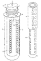
FIG. 6 shows a particularly advantageous embodiment of the device according to the invention. FIG. 6 a shows a tempering device 1 that comprises two tubular elements 1 a and 1 b. In both tubular elements, there are holes or arrangements of slots or similar openings 3. In FIG. 6 a, the two elements 1 a and 1 b are arranged such that the oval openings 3 on the right in FIG. 6 a overlap as shown in FIG. 6 a at the top. When the inside of the tubular elements are under increased air pressure, the gas can flow out through the overlapping openings of the elements 1 a and 1 b and contact the preform (not shown in FIG. 6 a for the sake of clarity). The slot-like openings do not overlap so that no gas is released through these openings.
In FIG. 6 b, the inner tubular section 1 b is rotated slightly to the right in comparison to FIG. 6 a. This causes the slot-shaped openings of elements 1 a and 1 b to overlap so that gas can exit through them if there is a gas overpressure in elements 1 a and 1 b. The exiting gas contacts the preform. The round or oval openings of the elements 1 a and 1 b in FIG. 6 b do not overlap so that no gas is released outwards through these openings.
Element 1 a is not completely shown in FIGS. 6 a and 6 b to reveal element 1 b in the bottom section of the figures. Element 1 a must be correspondingly extended in the bottom section of FIGS. 6 a and 6 b.
FIG. 7 a shows a sketch of a possible embodiment of the device according to the invention as well as the method according to the invention. A preheating device 6 serves to evenly heat the preform 2. Usually, the bottom finger-shaped region is preheated that is to be deformed in the blow molding process. The collar and the threaded area at the top section of the preform 2 are usually not or only slightly preheated.
The tempering device 1 that selectively preheats the preform is integrated in a blow mold device 7. The selectively tempered zones 10 are schematically represented in FIG. 7. The device 7 is used to fabricate and output a device by means of blow molding.
FIG. 7 b also shows a preheating device 6 that can be used to evenly heat preforms 2. The preheating device 6 follows a device that selectively and directly tempers the preform 2. The areas 10 that have been selectively tempered are formed in device 8. Device 8 follows a conventional blow molding device 9 that manufactures bottles from the selectively preheated preforms 2. Device 8 can for example be designed as a wheel that precedes a blow molding device 9.

Claims (19)

1. Device for the manufacture of bottles, comprising:
a preform;
a tempering device disposed within the preform to selectively and directly temper the preform, wherein the tempering device is adapted so that the preform can be tempered in zones that are one of along, perpendicular to, and at angle to the preform axis, and further wherein the tempering device comprises a first and a second tubular element that move in relationship to each other, whereby the gas outlet arrangement of the first tubular element is in a first, relative position of the tubular elements that can move in relationship to each other, whereby the first relative position causes an overlap with the gas outlet arrangement of the second tubular element to provide selective tempering, and the gas outlet arrangement of the first tubular elements is in a second relative position of the tubular elements that can move in relationship to each other, whereby the second relative position causes an overlap with the gas outlet arrangement of the second tubular element to provide even tempering.
2. Device according to claim 1, wherein the tempering device is a radiant heater to selectively heat the preform.
3. Device according to claim 1, wherein the tempering device comprises at least one gas inlet device and at least one gas outlet for contacting the preform with one of cooled and heated gas.
4. Device according to claim 3, wherein the tempering device comprises at least one gas inlet to receive gas from the preform.
5. Device according to claim 3, wherein one of the gas inlet and the gas outlet is formed by one of a slot, a hole, a nozzle and other aperture.
6. Device according to claim 3, wherein several gas inlets and several gas outlets are arranged in one of circles and lines.
7. Device according to claim 1, further comprising means to move the tempering device in and out of the preform.
8. Method for tempering preforms used in the manufacture of bottles, the method comprising:
selectively interactively tempering the preforms and directly tempering the inside of the preforms, wherein selectively tempering the preforms comprises using a stretch rod in a blow molding process, contacting the preforms with one of cooled and heated gas through at least one gas outlet opening, and applying the cooled heated gas by emitting the gas through a first gas outlet arrangement of a first tubular element, surrounding the first tubular element with a second tubular element with a second gas outlet arrangement, whereby the gas outlet arrangements of the first and second tubular element partially overlap in a first relative position between the first and second tubular elements, and then moving the first tubular element and second tubular element into a second relative position in which the gas outlet arrangement of the first and second tubular element at least partially overlap to provide even tempering;
inserting the stretch rod in a preheated preform;
selectively cooling the preform, whereby the stretch rod is not moved relative to the preform; and
stretching the preform which is blow molded via the stretch rod.
9. Method according to claim 8, further comprising selectively tempering the preforms in zones which are one of along, perpendicular to, and at an angle to the preform axis.
10. Method according to claim 8, further comprising evenly heating the preforms before the step of selective tempering.
11. Method according claim 8, wherein the preforms are tempered with a radiant heater.
12. Method according to claim 8, further comprising capturing the gas from the preforms by the tempering device.
13. Method according to claim 8, further comprising cooling the finished bottles by evenly tempering them.
14. Device according to claim 3, wherein the cooled and heated gas is air.
15. Device according to claim 1, wherein the movement of the first and second tubular element in relationship to each other is one of rotation and shifting.
16. Method according to claim 8, wherein the gas is air.
17. Device according to claim 1, further comprising a preheating device to evenly heat the preform.
18. Device according to claim 1, wherein the tempering device is at least partially integrated in the stretch rod of a blow molding device.
19. Device according to claim 17, wherein the tempering device is provided on a transport device by means of which the preheated preform released by the preheating device can be transported to a blow mold device.
US10/487,007 2001-09-11 2002-09-11 Device and method for controlling the temperature of preforms Expired - Fee Related US7687011B2 (en)

Applications Claiming Priority (4)

Application Number Priority Date Filing Date Title
DE10144537A DE10144537B4 (en) 2001-09-11 2001-09-11 Apparatus and method for tempering preforms
DE10144537 2001-09-11
DE10144537.7 2001-09-11
PCT/EP2002/010178 WO2003022551A1 (en) 2001-09-11 2002-09-11 Device and method for controlling the temperature of preforms

Publications (2)

Publication Number Publication Date
US20050046085A1 US20050046085A1 (en) 2005-03-03
US7687011B2 true US7687011B2 (en) 2010-03-30

Family

ID=7698509

Family Applications (1)

Application Number Title Priority Date Filing Date
US10/487,007 Expired - Fee Related US7687011B2 (en) 2001-09-11 2002-09-11 Device and method for controlling the temperature of preforms

Country Status (5)

Country Link
US (1) US7687011B2 (en)
EP (1) EP1425154B9 (en)
AT (1) ATE532620T1 (en)
DE (1) DE10144537B4 (en)
WO (1) WO2003022551A1 (en)

Cited By (4)

* Cited by examiner, † Cited by third party
Publication number Priority date Publication date Assignee Title
US20110236524A1 (en) * 2008-09-18 2011-09-29 Krones Ag Temperature-controlled stretching rod
EP1425154B2 (en) 2001-09-11 2015-07-08 Krones AG Device and method for controlling the temperature of preforms
US20150209998A1 (en) * 2014-01-28 2015-07-30 Gojo Industries, Inc. System and methods for preheating two stage preforms
CN109648824A (en) * 2019-01-29 2019-04-19 广州纯元科技有限公司 A kind of blowing device for plastic barrel production

Families Citing this family (7)

* Cited by examiner, † Cited by third party
Publication number Priority date Publication date Assignee Title
US7264464B2 (en) * 2003-06-09 2007-09-04 Husky Injection Molding Systems Ltd. Cooling tube with a low friction coating
DE102009035868A1 (en) 2009-07-31 2011-02-03 Krones Ag Device for forming plastic preforms with synchronous heating and stretching
DE102010007542A1 (en) * 2010-02-08 2011-08-11 KHS Corpoplast GmbH, 22145 Method and apparatus for blow molding containers
EP2447172A1 (en) * 2010-11-02 2012-05-02 Stefano Boido Apparatus for heating containers
US11198243B2 (en) * 2018-01-11 2021-12-14 Husky Injection Molding Systems Ltd. Method and apparatus for forming final-shaped containers using liquid to be contained therein
CN114080314A (en) * 2019-07-05 2022-02-22 费森尤斯卡比德国有限公司 Ampoule filled with chemical liquid, method for producing same, and apparatus for use in the method
DE102021131986A1 (en) 2021-12-03 2023-06-07 Wafios Aktiengesellschaft Apparatus for heating bar-shaped material and bending machine therewith

Citations (21)

* Cited by examiner, † Cited by third party
Publication number Priority date Publication date Assignee Title
US3439380A (en) * 1966-11-07 1969-04-22 Phillips Petroleum Co Apparatus for blow molding biaxially oriented articles
DE1816489A1 (en) 1968-12-23 1970-08-20 Heidenreich & Harbeck Gmbh Controlling wall thickness in the blowing - of hollow bodies
US3787170A (en) * 1971-05-13 1974-01-22 Phillips Petroleum Co Rapid heating of parison preforms
US3934743A (en) 1972-12-29 1976-01-27 American Can Company Blow molded, oriented plastic bottle and method for making same
US4151249A (en) 1978-01-05 1979-04-24 Owens-Illinois, Inc. Method of making a blown bottle with internal ribs
US4285657A (en) * 1979-12-03 1981-08-25 Ryder Leonard B Injection blow molding apparatus
DE2852061C2 (en) 1977-12-02 1984-10-04 Yoshino Kogyosho Co., Ltd., Tokio/Tokyo Method of making a bottle from a saturated polyester
JPS6061228A (en) * 1983-09-14 1985-04-09 Mitsubishi Plastics Ind Ltd Molding method of plastic bottle
JPS6073830A (en) 1983-09-30 1985-04-26 Katashi Aoki Method of blow molding of container such as flat or rectangular bottle
US4564497A (en) 1982-07-28 1986-01-14 Yoshino Kogyosho Co., Ltd. Method of producing bottles of saturated polyester
US4605839A (en) * 1984-12-21 1986-08-12 Adolph Coors Company Dual parison heating reflector and method
JPS6277919A (en) 1985-10-01 1987-04-10 Mitsubishi Plastics Ind Ltd Blow molding method for bottle
JPH0449023A (en) 1990-06-18 1992-02-18 Toppan Printing Co Ltd Manufacture of plastic bottle
US5232641A (en) 1991-01-25 1993-08-03 Williamson James T Rapid cool process
US5256341A (en) * 1991-07-01 1993-10-26 Sidel Method and apparatus for infrared heating of plastic preforms
JPH06198719A (en) 1992-09-25 1994-07-19 Nissei Asb Mach Co Ltd Biaxial stretching blow molding method for self-standing bottle and preform used therefor
JPH06278196A (en) 1993-03-25 1994-10-04 Nissei Asb Mach Co Ltd Blow molding machine
JPH0919957A (en) 1995-07-06 1997-01-21 Kao Corp Molding method for plastic bottle having narrow part
DE19608570A1 (en) 1996-03-06 1997-09-11 Krupp Corpoplast Masch Process for tempering preforms and device for tempering
EP0947304A2 (en) 1998-03-31 1999-10-06 Husky Injection Molding Systems Ltd. Preform post-mold cooling method
JP2000343590A (en) * 1999-06-02 2000-12-12 Toyo Seikan Kaisha Ltd Method and apparatus for producing biaxially stretched blow molded container

Family Cites Families (3)

* Cited by examiner, † Cited by third party
Publication number Priority date Publication date Assignee Title
JPS57117929A (en) 1981-01-16 1982-07-22 Dainippon Printing Co Ltd Manufacture of biaxially stretched saturated polyester resin container by blow molding
US5290506A (en) * 1991-04-30 1994-03-01 Nissei Asb Machine Co., Ltd. Process of injection stretch blow molding hollow article having thick-walled bottom
DE10144537B4 (en) 2001-09-11 2010-07-22 Krones Ag Apparatus and method for tempering preforms

Patent Citations (22)

* Cited by examiner, † Cited by third party
Publication number Priority date Publication date Assignee Title
US3439380A (en) * 1966-11-07 1969-04-22 Phillips Petroleum Co Apparatus for blow molding biaxially oriented articles
DE1816489A1 (en) 1968-12-23 1970-08-20 Heidenreich & Harbeck Gmbh Controlling wall thickness in the blowing - of hollow bodies
US3787170A (en) * 1971-05-13 1974-01-22 Phillips Petroleum Co Rapid heating of parison preforms
US3934743A (en) 1972-12-29 1976-01-27 American Can Company Blow molded, oriented plastic bottle and method for making same
DE2852061C2 (en) 1977-12-02 1984-10-04 Yoshino Kogyosho Co., Ltd., Tokio/Tokyo Method of making a bottle from a saturated polyester
US4151249A (en) 1978-01-05 1979-04-24 Owens-Illinois, Inc. Method of making a blown bottle with internal ribs
US4285657A (en) * 1979-12-03 1981-08-25 Ryder Leonard B Injection blow molding apparatus
US4564497A (en) 1982-07-28 1986-01-14 Yoshino Kogyosho Co., Ltd. Method of producing bottles of saturated polyester
JPS6061228A (en) * 1983-09-14 1985-04-09 Mitsubishi Plastics Ind Ltd Molding method of plastic bottle
JPS6073830A (en) 1983-09-30 1985-04-26 Katashi Aoki Method of blow molding of container such as flat or rectangular bottle
US4605839A (en) * 1984-12-21 1986-08-12 Adolph Coors Company Dual parison heating reflector and method
JPS6277919A (en) 1985-10-01 1987-04-10 Mitsubishi Plastics Ind Ltd Blow molding method for bottle
JPH0449023A (en) 1990-06-18 1992-02-18 Toppan Printing Co Ltd Manufacture of plastic bottle
US5232641A (en) 1991-01-25 1993-08-03 Williamson James T Rapid cool process
US5256341A (en) * 1991-07-01 1993-10-26 Sidel Method and apparatus for infrared heating of plastic preforms
EP0521773B1 (en) 1991-07-01 1995-02-01 SIDEL, Société Anonyme Method and apparatus for heating plastic preforms, particularly made of PET, by infrared radiation for the production of containers
JPH06198719A (en) 1992-09-25 1994-07-19 Nissei Asb Mach Co Ltd Biaxial stretching blow molding method for self-standing bottle and preform used therefor
JPH06278196A (en) 1993-03-25 1994-10-04 Nissei Asb Mach Co Ltd Blow molding machine
JPH0919957A (en) 1995-07-06 1997-01-21 Kao Corp Molding method for plastic bottle having narrow part
DE19608570A1 (en) 1996-03-06 1997-09-11 Krupp Corpoplast Masch Process for tempering preforms and device for tempering
EP0947304A2 (en) 1998-03-31 1999-10-06 Husky Injection Molding Systems Ltd. Preform post-mold cooling method
JP2000343590A (en) * 1999-06-02 2000-12-12 Toyo Seikan Kaisha Ltd Method and apparatus for producing biaxially stretched blow molded container

Cited By (6)

* Cited by examiner, † Cited by third party
Publication number Priority date Publication date Assignee Title
EP1425154B2 (en) 2001-09-11 2015-07-08 Krones AG Device and method for controlling the temperature of preforms
US20110236524A1 (en) * 2008-09-18 2011-09-29 Krones Ag Temperature-controlled stretching rod
US8608471B2 (en) 2008-09-18 2013-12-17 Krones Ag Temperature-controlled stretching rod
US20150209998A1 (en) * 2014-01-28 2015-07-30 Gojo Industries, Inc. System and methods for preheating two stage preforms
CN109648824A (en) * 2019-01-29 2019-04-19 广州纯元科技有限公司 A kind of blowing device for plastic barrel production
CN109648824B (en) * 2019-01-29 2021-03-02 广州纯元科技有限公司 Blow molding device for plastic barrel production

Also Published As

Publication number Publication date
EP1425154B1 (en) 2011-11-09
ATE532620T1 (en) 2011-11-15
US20050046085A1 (en) 2005-03-03
EP1425154B9 (en) 2016-02-10
DE10144537A1 (en) 2003-03-27
EP1425154B2 (en) 2015-07-08
DE10144537B4 (en) 2010-07-22
EP1425154A1 (en) 2004-06-09
WO2003022551A1 (en) 2003-03-20

Similar Documents

Publication Publication Date Title
JP4358715B2 (en) Molded product cooling system and cooling method, cooling pin
US4473515A (en) Injection blow molding method
US7687011B2 (en) Device and method for controlling the temperature of preforms
US4151248A (en) Method for the preparation of hollow plastic articles
US4285657A (en) Injection blow molding apparatus
JP5516912B2 (en) Molding means
JP4146234B2 (en) Method for producing a polyethylene terephthalate container having a mouth offset from the center
PL172400B1 (en) Stress relieving in blow-moulded products and their heat treatment
CA2430598A1 (en) Post mold cooling method and apparatus
US4323341A (en) Apparatus for forming hollow plastic objects
JP7457077B2 (en) Manufacturing method of bent-neck container, temperature adjustment mold, blow molding device, and blow molding method
US20110140315A1 (en) Blow moulding machine having a cooling device
ITPN960025A1 (en) PROCESS AND IMPROVED PLANT FOR THE PRODUCTION OF PREFORMS IN THERMOPLASTIC RESIN
US4087227A (en) Mold for thermal conditioning a thermoplastic parison
JPH06179238A (en) Injection stretch blow molding machine
US4206171A (en) Method for thermal conditioning a thermoplastic parison
US20150021343A1 (en) Blow molding method, blow mold, and blow-molded container
JP3255485B2 (en) Blow molding machine
GB2126156A (en) A method of controlling the temperature of a parison during injection stretch-blow moulding
US6682690B2 (en) Core rod positioning method
JP3798873B2 (en) One-stage machine and method for manufacturing containers made of thermoplastic material
US3505440A (en) Method and apparatus for blow molding
JPH0649329B2 (en) Method and device for adjusting temperature of parison in injection stretch blow molding
JPH0699482A (en) Method and apparatus for controlling temperature of preform
WO2020184563A1 (en) Method for producing resin container and apparatus for producing resin container

Legal Events

Date Code Title Description
AS Assignment

Owner name: KRONES AG, GERMANY

Free format text: ASSIGNMENT OF ASSIGNORS INTEREST;ASSIGNORS:VOTH, KLAUS;ASBRAND, HELMUT;DEYERL, HEINRICHI;REEL/FRAME:015674/0261

Effective date: 20040422

Owner name: KRONES AG,GERMANY

Free format text: ASSIGNMENT OF ASSIGNORS INTEREST;ASSIGNORS:VOTH, KLAUS;ASBRAND, HELMUT;DEYERL, HEINRICHI;REEL/FRAME:015674/0261

Effective date: 20040422

FPAY Fee payment

Year of fee payment: 4

FEPP Fee payment procedure

Free format text: MAINTENANCE FEE REMINDER MAILED (ORIGINAL EVENT CODE: REM.)

LAPS Lapse for failure to pay maintenance fees

Free format text: PATENT EXPIRED FOR FAILURE TO PAY MAINTENANCE FEES (ORIGINAL EVENT CODE: EXP.)

STCH Information on status: patent discontinuation

Free format text: PATENT EXPIRED DUE TO NONPAYMENT OF MAINTENANCE FEES UNDER 37 CFR 1.362

FP Lapsed due to failure to pay maintenance fee

Effective date: 20180330