US7686841B2 - Rotating balloon expandable sheath bifurcation delivery system - Google Patents
Rotating balloon expandable sheath bifurcation delivery system Download PDFInfo
- Publication number
- US7686841B2 US7686841B2 US10/747,546 US74754603A US7686841B2 US 7686841 B2 US7686841 B2 US 7686841B2 US 74754603 A US74754603 A US 74754603A US 7686841 B2 US7686841 B2 US 7686841B2
- Authority
- US
- United States
- Prior art keywords
- stent
- proximal
- end region
- catheter assembly
- balloon
- Prior art date
- Legal status (The legal status is an assumption and is not a legal conclusion. Google has not performed a legal analysis and makes no representation as to the accuracy of the status listed.)
- Expired - Fee Related
Links
Images


Classifications
-
- A—HUMAN NECESSITIES
- A61—MEDICAL OR VETERINARY SCIENCE; HYGIENE
- A61F—FILTERS IMPLANTABLE INTO BLOOD VESSELS; PROSTHESES; DEVICES PROVIDING PATENCY TO, OR PREVENTING COLLAPSING OF, TUBULAR STRUCTURES OF THE BODY, e.g. STENTS; ORTHOPAEDIC, NURSING OR CONTRACEPTIVE DEVICES; FOMENTATION; TREATMENT OR PROTECTION OF EYES OR EARS; BANDAGES, DRESSINGS OR ABSORBENT PADS; FIRST-AID KITS
- A61F2/00—Filters implantable into blood vessels; Prostheses, i.e. artificial substitutes or replacements for parts of the body; Appliances for connecting them with the body; Devices providing patency to, or preventing collapsing of, tubular structures of the body, e.g. stents
- A61F2/82—Devices providing patency to, or preventing collapsing of, tubular structures of the body, e.g. stents
- A61F2/856—Single tubular stent with a side portal passage
-
- A—HUMAN NECESSITIES
- A61—MEDICAL OR VETERINARY SCIENCE; HYGIENE
- A61F—FILTERS IMPLANTABLE INTO BLOOD VESSELS; PROSTHESES; DEVICES PROVIDING PATENCY TO, OR PREVENTING COLLAPSING OF, TUBULAR STRUCTURES OF THE BODY, e.g. STENTS; ORTHOPAEDIC, NURSING OR CONTRACEPTIVE DEVICES; FOMENTATION; TREATMENT OR PROTECTION OF EYES OR EARS; BANDAGES, DRESSINGS OR ABSORBENT PADS; FIRST-AID KITS
- A61F2/00—Filters implantable into blood vessels; Prostheses, i.e. artificial substitutes or replacements for parts of the body; Appliances for connecting them with the body; Devices providing patency to, or preventing collapsing of, tubular structures of the body, e.g. stents
- A61F2/95—Instruments specially adapted for placement or removal of stents or stent-grafts
- A61F2/954—Instruments specially adapted for placement or removal of stents or stent-grafts for placing stents or stent-grafts in a bifurcation
-
- A—HUMAN NECESSITIES
- A61—MEDICAL OR VETERINARY SCIENCE; HYGIENE
- A61F—FILTERS IMPLANTABLE INTO BLOOD VESSELS; PROSTHESES; DEVICES PROVIDING PATENCY TO, OR PREVENTING COLLAPSING OF, TUBULAR STRUCTURES OF THE BODY, e.g. STENTS; ORTHOPAEDIC, NURSING OR CONTRACEPTIVE DEVICES; FOMENTATION; TREATMENT OR PROTECTION OF EYES OR EARS; BANDAGES, DRESSINGS OR ABSORBENT PADS; FIRST-AID KITS
- A61F2/00—Filters implantable into blood vessels; Prostheses, i.e. artificial substitutes or replacements for parts of the body; Appliances for connecting them with the body; Devices providing patency to, or preventing collapsing of, tubular structures of the body, e.g. stents
- A61F2/95—Instruments specially adapted for placement or removal of stents or stent-grafts
- A61F2/958—Inflatable balloons for placing stents or stent-grafts
-
- A—HUMAN NECESSITIES
- A61—MEDICAL OR VETERINARY SCIENCE; HYGIENE
- A61F—FILTERS IMPLANTABLE INTO BLOOD VESSELS; PROSTHESES; DEVICES PROVIDING PATENCY TO, OR PREVENTING COLLAPSING OF, TUBULAR STRUCTURES OF THE BODY, e.g. STENTS; ORTHOPAEDIC, NURSING OR CONTRACEPTIVE DEVICES; FOMENTATION; TREATMENT OR PROTECTION OF EYES OR EARS; BANDAGES, DRESSINGS OR ABSORBENT PADS; FIRST-AID KITS
- A61F2/00—Filters implantable into blood vessels; Prostheses, i.e. artificial substitutes or replacements for parts of the body; Appliances for connecting them with the body; Devices providing patency to, or preventing collapsing of, tubular structures of the body, e.g. stents
- A61F2/82—Devices providing patency to, or preventing collapsing of, tubular structures of the body, e.g. stents
- A61F2/86—Stents in a form characterised by the wire-like elements; Stents in the form characterised by a net-like or mesh-like structure
- A61F2/90—Stents in a form characterised by the wire-like elements; Stents in the form characterised by a net-like or mesh-like structure characterised by a net-like or mesh-like structure
- A61F2/91—Stents in a form characterised by the wire-like elements; Stents in the form characterised by a net-like or mesh-like structure characterised by a net-like or mesh-like structure made from perforated sheet material or tubes, e.g. perforated by laser cuts or etched holes
-
- A—HUMAN NECESSITIES
- A61—MEDICAL OR VETERINARY SCIENCE; HYGIENE
- A61F—FILTERS IMPLANTABLE INTO BLOOD VESSELS; PROSTHESES; DEVICES PROVIDING PATENCY TO, OR PREVENTING COLLAPSING OF, TUBULAR STRUCTURES OF THE BODY, e.g. STENTS; ORTHOPAEDIC, NURSING OR CONTRACEPTIVE DEVICES; FOMENTATION; TREATMENT OR PROTECTION OF EYES OR EARS; BANDAGES, DRESSINGS OR ABSORBENT PADS; FIRST-AID KITS
- A61F2210/00—Particular material properties of prostheses classified in groups A61F2/00 - A61F2/26 or A61F2/82 or A61F9/00 or A61F11/00 or subgroups thereof
- A61F2210/0076—Particular material properties of prostheses classified in groups A61F2/00 - A61F2/26 or A61F2/82 or A61F9/00 or A61F11/00 or subgroups thereof multilayered, e.g. laminated structures
Definitions
- Catheter systems such as angioplasty catheters, and stent delivery systems, as well as the stents associated therewith, are widely used in the treatment of stenoses, aneurysms, lesions, and other abnormalities within blood vessels and other body lumens.
- Intravascular stents are used in coronary, renal, and carotid arteries, for example, to maintain an open passage through the artery.
- stents In patients whose coronary heart disease consists of focal lesions, stents have proven effective. For example, where only a single coronary artery is clogged or where there are short blockages in more than a single artery, stents have been used with a great amount of success.
- An intravascular stent may be positioned in a clogged artery by a catheter and is often set in place by inflating a balloon upon which the stent is mounted. This expands the diameter of the stent and opens the previously clogged artery. The balloon is then deflated and removed from the patient while the stent retains an open passage through the artery.
- a stent delivery system employing a stent assembly with branches intended for deployment in the adjacent branches of a vessel bifurcation has been proposed to allow placement of a portion of the assembly in both a primary passage, such as an artery, and a secondary passage, such as a side branch artery. Additionally, these stents generally have an opening which allows for unimpeded blood flow into the side branch artery. However, problems are still encountered in orienting the stent relative to the side branch at the bifurcation of the primary and secondary passages. Moreover, such bifurcated assemblies are typically specially manufactured at an increased cost over a more standard stent intended for single vessel deployment.
- Some embodiments of the present invention include a freely rotating deployment assembly for a stent assembly for maintaining side branch access and protection.
- At least one embodiment of the invention includes a medical device with a balloon catheter shaft and a rotating sheath such as is described in U.S. patent application Ser. No. 10/375,689, filed Feb. 27, 2003 and U.S. patent application Ser. No. 10/657,472, filed Sep. 8, 2003 both of which are entitled Rotating Balloon Expandable Sheath Bifurcation Delivery, the entire content of both being incorporated herein by reference, wherein the ends of the sheath and/or stent are provided with one or more protective elements.
- the sheath has one or more end regions and an intermediate region, wherein the intermediate region has an outer diameter less than that of either or both end regions.
- the intermediate region defines a stent mounting region wherein the stent is disposed prior to delivery between end regions of the sheath.
- one or both cones of the balloon prior to expansion have a diameter that is greater than the unexpanded or predeployed diameter of the sheath and/or stent disposed thereon.
- the catheter further comprises one or more end sleeves or socks, wherein each sleeve has a first end engaged to the catheter shaft adjacent to an end of the balloon. In some embodiments the first end of each sleeve is freely rotatable about the catheter shaft. In at least one embodiment, a sleeve has a second end, which prior to deployment of the stent, is disposed about an end of the stent and during deployment of the stent is retracted therefrom to release the stent into a body lumen.
- a proximal sleeve is engaged to the proximal end of the stent and a distal sleeve is engaged to a distal end of the stent.
- a single sleeve is engaged to only one end of the stent prior to deployment.
- the medical device comprises a secondary guidewire lumen housing, which itself comprises a reinforcing member, such as a polymer tube of PEBAX, peek, polyimide, etc., a braided tube of metal wire or other material, a hypotube, or other device engaged to the sheath and engaged to the collar.
- a reinforcing member such as a polymer tube of PEBAX, peek, polyimide, etc., a braided tube of metal wire or other material, a hypotube, or other device engaged to the sheath and engaged to the collar.
- an inner member is positioned within the reinforcing member to define the secondary guidewire lumen.
- the material of the inner member is more flexible than the material of the reinforcing member.
- the inner member is longer than the reinforcing member and at least one end of the inner member extends beyond at least one end of the reinforcing member.
- the inner member is concentrically disposed within the reinforcing member. In some embodiments the inner member is asymmetrically disposed within the reinforcing member.
- the proximal end of the reinforcing member is proximally adjacent to the stent. In some embodiments the proximal end of the reinforcing member is tapered. In at least one embodiment the reinforcing member is positioned such that at least a portion of the reinforcing member is radially offset from the distal end of the stent.
- the rotatable sheath has a length longer than the stent.
- one or both ends of the sheath are folded back over the corresponding ends of the stent prior to delivery.
- the one or both ends of the sheath slidingly retract off of the stent, thereby freeing the ends of the stent for deployment.
- only the distal end of the sheath is folded over the distal end of the stent prior to delivery.
- the proximal end of the sheath defines a proximal slit or is tapered to accommodate the position of the secondary guidewire lumen housing, such that the proximal end of the sheath may be folded over at least a portion of the proximal end of the stent prior to delivery.
- FIG. 1 is a side view of an embodiment of the invention, comprising a rotating sheath assembly.
- FIG. 2 is a side view of the embodiment shown in FIG. 1 shown configured for delivery of a stent.
- FIG. 3 is a side view of an embodiment of the invention comprising a catheter assembly.
- the catheter assembly is provided with a rotating collar.
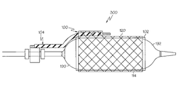
- FIG. 4 is a side view of the catheter assembly of FIG. 3 and further comprising the rotating sheath assembly and stent of FIG. 2 .
- FIG. 5 is a side view of an embodiment of the invention wherein the catheter assembly of FIG. 4 is shown being advanced along a guidewire to a vessel bifurcation prior to delivery of the stent.
- FIG. 6 is a side perspective view of an embodiment of the invention comprising a stent, such as that shown in FIG. 2 .
- FIG. 7 is a side perspective view of the stent shown in FIG. 6 wherein a side branch opening is shown formed from the enlargement of a cell opening in the stent wall.
- FIG. 8 is a cross-sectional view of the stent of FIG. 7 .
- FIG. 9 is a side view of the stent depicted in FIG. 5 , wherein the stent has been delivered from the catheter assembly, by balloon expansion and the assembly subsequently withdrawn from the vessel(s).
- FIG. 10 is a side view of an embodiment of the embodiment of the invention shown in FIG. 4 which includes protective sleeves.
- FIG. 11 is a cross-sectional view of a portion of the system shown in FIG. 10 corresponding to section A.
- FIG. 12 is a cross-sectional view of a portion of the system shown in FIG. 10 corresponding to section B.
- FIG. 13 is a side view of the embodiment shown in FIG. 10 wherein the sleeves have been retracted from the ends of the stent.
- FIG. 14 is a side view of an embodiment of the invention wherein each end of the rotating sheath is folded over the corresponding end of the stent.
- FIG. 15 is a side view of the embodiment shown in FIG. 14 , wherein the ends of the sheath have been retracted off of the stent.
- FIG. 16 is a side view of an embodiment of the invention wherein each end of the rotating sheath is folded over the corresponding end of the stent and the proximal end of the sheath defines a slot.
- FIG. 17 is a side view of the embodiment shown in FIG. 16 , wherein the ends of the sheath have been retracted off of the stent.
- FIG. 18 is a side view of an embodiment of the invention wherein the rotating sheath comprises a pair raised end portions or hubs.
- FIG. 19 is a side view of an embodiment of the invention shown in FIG. 18 wherein the secondary guidewire housing comprises a bent portion over the proximal hub of the rotating sheath.
- FIG. 20 is a side view of an embodiment of the invention wherein the rotating sheath comprises a pair raised end portions or hubs, wherein the proximal hub defines a passage for the secondary guidewire housing.
- FIG. 21 is a side view of an embodiment of the invention wherein the secondary guidewire housing is radially offset from the proximal end of the stent.
- FIG. 22 is a cross-sectional view of a portion of the system shown in FIG. 21 corresponding to section C.
- FIG. 23 is a side view of an embodiment of the invention wherein the secondary guidewire housing comprises a step which is radially offset from the proximal end of the stent.
- FIG. 24 is a side view of an embodiment of the invention wherein the cones of the balloon are provided with a puffed configuration in the unexpanded state.
- FIG. 25 is a side view of an embodiment of the invention wherein only the distal cone of the balloon is provided with a puffed configuration in the unexpanded state.
- FIG. 26 is a side view of either of the embodiments shown in FIGS. 24 and 25 , wherein the balloon is shown in an expanded state.
- FIG. 1 a rotating sheath assembly 100 is shown which comprises a tubular sleeve or sheath 102 and a positioning or secondary guidewire housing 104 .
- the housing 104 defines a secondary guidewire lumen 106 through which a secondary guidewire 108 may be passed.
- the housing 104 may be constructed of a wide variety of materials including metal plastic, etc., in at least one embodiment the housing 104 is an external reinforcing member or hypotube 64 .
- the hypotube 64 may comprise stainless steel, one or more polymer materials or other material.
- the housing 104 is provided with one or more openings 110 along its length. In at least one embodiment the housing 104 is spiral cut to provide at least a continuous opening 110 which acts to provide improve the flexibility of the housing 104 .
- the secondary guidewire housing 104 further comprises an inner shaft 103 , about which the hypotube 64 is disposed.
- the inner shaft 103 and hypotube 64 may be of a single piece construction wherein the housing 104 is formed using a ‘bumped’ extrusion and then scored for improved flexibility.
- the inner shaft 103 is a flexible hollow tubular member which extends distally beyond the distal end of the hypotube 64 .
- both the hypotube 64 and the inner shaft 103 are scored, cut or otherwise provided with improved flexibility over a more rigid continuous shaft.
- flexibility of the housing 104 may be improved by manufacturing the housing 104 , or a portion thereof, to include segmented rings; a pattern of cuts, indentations, etc; and or a corrugated construction.
- This distal and/or proximal tips 105 of the inner shaft 103 provides the housing with a flexible protective sheath about the guidewire 108 as it passes out of the secondary guidewire lumen 106 .
- a protective covering may prevent the guidewire 108 from excessively rubbing against the wall 201 of the vessel 199 , such as in the manner depicted in FIG. 5 ; even where the secondary guidewire 108 exits the secondary lumen 106 at a significant angle.
- the inner shaft 103 may be constructed of any of a variety of flexible materials such as: high density polyurethane (HDPE), PEBAX, nylon, urethane, and/or other materials in a single layer, multi-layer and/or braided configuration.
- the shaft 144 of the catheter 116 defines a primary guidewire housing 211 through which a primary guidewire 107 may be advanced.
- guidewires 107 and 108 are passed through a lumen or other body vessel 209 to a bifurcation 203 .
- Primary guidewire 107 is then advanced into a primary branch of passage 205 of the bifurcation 203 while the secondary guidewire 108 is advanced into the adjacent or secondary branch 207 of the bifurcation 203 .
- the rotatable sleeve 104 will rotate the stent 120 into a desired position so that the secondary opening 130 a of the stent is aligned with the secondary passage 207 .
- the system 300 is a fixed wire system, and as such the use of the primary guidewire is unnecessary.
- the catheter 116 is an over-the-wire, MONORAIL®, or other type of catheter 116 which requires the primary guidewire 107 .
- At least a distal portion of the housing 104 is engaged to at least a proximal portion of the sheath 102 at an engagement site 112 .
- the manner or mechanism of engagement between the sheath and housing 104 may be by bonding, welding, adhering adhesively engaging, mechanically engaging or otherwise connecting the surfaces of the respective sheath 102 and housing 104 .
- the sheath 102 is a hollow tube of sheath material that is configured to be placed over the balloon 114 or other region of a catheter 116 , such as in the manner illustrated in FIGS. 3 and 4 .
- the sheath 102 is further configured to be rotatable about the catheter shaft and/or balloon 114 , even when a stent 120 has been positioned about and/or affixed to the sheath 102 .
- the sheath 102 may be constructed of a variety of low friction materials such as PTFE, HDPE, etc.
- the sheath 102 is at least partially constructed of a hydrophilic material, such as hydrophilic polymers such as; TECOPHILIC® material available from Thermedics Polymer Products, a division of VIASYS Healthcare of Wilmington, Mass.; TECOTHANE®, also available from Thermedics Polymer Products; hydrophilic polyurethanes, and/or aliphatic, polyether-based thermoplastic hydrophilic polyurethane; and any other material that provides the sheath 102 with the ability to rotate freely about the balloon 114 when in the “wet” state, such as when the catheter is exposed to body fluids during advancement through a vessel.
- hydrophilic polymers such as; TECOPHILIC® material available from Thermedics Polymer Products, a division of VIASYS Healthcare of Wilmington, Mass.; TECOTHANE®, also available from Thermedics Polymer Products; hydrophilic polyurethanes, and/or aliphatic, polyether-based thermoplastic hydrophilic polyurethane; and
- Suitable sheath materials may also provide the sheath with rotatability in the “dry”, or pre-insertion, state, but with the application of a greater amount of force than when in the wet state, such materials are referred to herein as being tecophilic.
- a sheath 102 at least partially constructed from tecophilic material provides the sheath 102 with the ability to rotate freely about the balloon 114 when in the “wet” state, such as when the catheter is exposed to body fluids during advancement through a vessel.
- the tecophilic sheath 102 is also capable of rotation in the “dry”, or pre-insertion, state, but with the application of a greater amount of force than when in the wet state.
- the sheath 102 may be constructed of one or multiple materials, in one or more layers.
- the sheath 102 may comprise an outer layer of a softer material than that of the material used in constructing an inner layer, such as has been previously described.
- the sheath 102 may be comprised of a matrix of a first material 111 and have one or more supportive stripes, strands, members or areas of a second supportive material 113 within, external to or internal to such a matrix.
- composition of the sheath 102 material may include essentially any appropriate polymer or other suitable materials.
- suitable polymers include Hydrophilic Polyurethanes, Aromatic Polyurethanes, Polycarbonate base Aliphatic Polyurethanes, Engineering polyurethane, Elastomeric polyamides, block polyamide/ethers, polyether block amide (PEBA, for example available under the trade name PEBAX), and Silicones, Polyetherester (for example a polyether-ester elastomer such as Arnitel available from DSM Engineering Plastics), Polyester (for example a polyester elastomer such as Hytrel available from Du Pont), or linear low density polyethylene (for example Rexell).
- Hydrophilic Polyurethanes Aromatic Polyurethanes, Polycarbonate base Aliphatic Polyurethanes, Engineering polyurethane, Elastomeric polyamides, block polyamide/ethers, polyether block amide (PEBA, for example available under the trade name PEBAX), and Silicones
- Polyetherester for
- Example of suitable re-inforcing materials whether alone or blended with other materials, mixtures or combination or copolymers include all Polyamides (for example, Durethan available from Bayer or Cristamid available from ELF Atochem), polyethylene (PE). Marlex high-density polyethylene, polyetheretherketone (PEEK), polyimide (PI), and polyetherimide (PEI), liquid crystal polymers (LCP), and Acetal (Delrin or Celcon).
- Polyamides for example, Durethan available from Bayer or Cristamid available from ELF Atochem
- PE polyethylene
- Marlex high-density polyethylene polyetheretherketone
- PI polyimide
- PEI polyetherimide
- LCP liquid crystal polymers
- Acetal Delrin or Celcon
- the inner surface of the sheath 102 or the outer surface of the balloon 114 may include a coating of one or more low friction materials or include one or more low friction materials in its construction.
- a coating 401 is shown in FIG. 3 , as being depicted on the surface of the balloon 114 before assembly 100 has been placed thereabout, such as is depicted in FIG. 4 . Coating 401 may however by placed between the balloon 114 and sheath 102 at any time.
- a suitable coating material include but are not limited to: hydrogel, silicon, and/or BIOSLIDE® available from SciMed Life Systems, Inc. of Maple Grove Minn.
- the sheath 102 is configured to be freely rotatable about a balloon of a catheter even when a stent 120 , such as is shown in FIGS. 2 and 4 is crimped onto the sheath 102 .
- a proximal portion 122 of the stent 120 is also disposed about at least a portion of the secondary guidewire housing 104 .
- at least a portion of the housing 104 and/or the secondary guidewire 108 extends distally through a cell opening 130 of the stent 120 .
- Stent 120 may be a stent, such as is shown in FIG. 6 , which is at least partially constructed of a plurality of interconnected struts, connectors or members 132 .
- the stent 132 defines a proximal opening 134 , a distal opening 136 and a flow path 138 therebetween.
- the cell openings 130 are in fluid communication with the flow path 138 .
- the members 132 that define the selected cell opening 130 a may be distorted or modified in order to accommodate the passage of secondary guidewire 108 and/or the secondary guidewire housing 104 therethrough.
- the modified cell opening 130 a hereinafter referred to as secondary opening 130 a , is positioned on the stent 120 between the proximal opening 134 and the distal opening 136 and is depicted in FIGS. 7 and 8 . It is noted that any type of stent may be provided with secondary opening 130 a and that the present invention is not limited to only the particular type of stent design, configuration or structure shown.
- the distortion of the secondary opening 130 a and the adjacent members 132 is of a minimal extent, and is provide only to allow sliding passage of the secondary guidewire 108 , and if desired a distal portion of the secondary guidewire housing 104 , through the secondary opening 130 a .
- the actual size of the secondary opening 130 a may be substantially similar, or only marginally different than that of the surrounding cell openings 130 .
- stent 120 may be a standard “single vessel” stent that is provided with a secondary opening 130 a in the manner described above, the stent 120 may also be a bifurcated stent having a trunk or stem portion, with one or more leg portions and/or branch openings adjacent thereto, through one of which the secondary guidewire may be passed.
- Such bifurcated stents and stent assemblies are well known in the art.
- the stent 120 may be configured to deliver one or more therapeutic agents to a delivery site such as within the vessel 199 or one or more areas adjacent thereto, such as shown in FIGS. 5 and 9 .
- one or stent members 132 such as is shown in FIG. 6 , maybe configured to include one or more holes, notches, or other surface features to which one or more therapeutic agents 400 may be placed for delivery to the aneurysm site.
- a therapeutic agent may be placed on the stent in the form of a coating.
- the coating includes at least one therapeutic agent and at least one polymer.
- a therapeutic agent may be a drug, a non-genetic agent, a genetic agent, etc.
- suitable non-genetic therapeutic agents include but a re not limited to: anti-thrombogenic agents such as heparin, heparin derivatives, urokinase, and PPack (dextrophenylalanine proline arginine chloromethylketone); anti-proliferative agents such as enoxaprin, angiopeptin, monoclonal antibodies capable of blocking smooth muscle cell proliferation, hirudin, and acetylsalicylic acid; anti-inflammatory agents such as dexamethasone, prednisolone, corticosterone, budesonide, estrogen, sulfasalazine, and mesalamine; antineoplastic/antiproliferative/anti-miotic agents such as paclitaxel, 5-fluorouracil, cisplatin, vinblastine, vincristine, epothilones, endo
- an agent may include but is not limited to: anti-sense DNA and RNA; DNA coding for anti-sense RNA, tRNA or rRNA to replace defective or deficient endogenous molecules; angiogenic factors including growth factors such as acidic and basic fibroblast growth factors, vascular endothelial growth factor, epidermal growth factor, transforming growth factor ⁇ and ⁇ , platelet-derived endothelial growth factor, platelet-derived growth factor, tumor necrosis factor ⁇ , hepatocyte growth factor and insulin like growth factor; cell cycle inhibitors including CD inhibitors, thymidine kinase (“TK”) and other agents useful for interfering with cell proliferation; at least one of the family of bone morphogenic proteins (“BMP's”) such as BMP-2, BMP-3, BMP-4, BMP-5, BMP-6 (Vgr-1), BMP-7 (OP-1), BMP-8, BMP-9, BMP-10, BMP-11, BMP-12, BMP-13
- BMP's bone morphogenic proteins
- BMP-2, BMP-3, BMP-4, BMP-5, BMP-6 and BMP-7 Any of BMP-2, BMP-3, BMP-4, BMP-5, BMP-6 and BMP-7; dimeric proteins such as homodimers, heterodimers, or combinations thereof, alone or together with other molecules; molecules capable of inducing an upstream or downstream effect of a BMP such as “hedgehog” proteins, or the DNA's encoding them and any combinations thereof.
- the cellular material may include but is not limited to: cells of human origin (autologous or allogeneic); cells of non-human origin (xenogeneic) and any combination thereof.
- cellular material include but are not limited to the following:
- a therapeutic agent comprises at least one polymer agent or coating
- the at least one coating may include but is not limited to: polycarboxylic acids; cellulosic polymers, including cellulose acetate and cellulose nitrate; gelatin; polyvinylpyrrolidone; cross-linked polyvinylpyrrolidone; polyanhydrides including maleic anhydride polymers; polyamides; polyvinyl alcohols; copolymers of vinyl monomers such as EVA; polyvinyl ethers; polyvinyl aromatics; polyethylene oxides; glycosaminoglycans; polysaccharides; polyesters including polyethylene terephthalate; polyacrylamides; polyethers; polyether sulfone; polycarbonate; polyalkylenes including polypropylene, polyethylene and high molecular weight polyethylene; halogenated polyalkylenes including polytetrafluoroethylene; polyurethanes; polyorthoesters; proteins; polypeptides; silicones; silox
- an example of a suitable polymer agent or coating comprises block copolymers comprising at least one A block and at least one B block.
- the A blocks are preferably soft elastomeric blocks, which are based upon one or more polyolefins, or other polymer with a glass transition temperature at or below room temperature.
- the A blocks can be polyolefinic blocks having alternating quaternary and secondary carbons of the general formulation: —(CRR′—CH 2 ) n —, where R and R′ are, independently, linear or branched aliphatic groups such as methyl, ethyl, propyl, isopropyl, butyl, isobutyl and so forth, or represent cyclic aliphatic groups such as cyclohexane, cyclopentane, and the like, either with or without pendant groups.
- Preferred polyolefinic blocks include polymeric blocks of isobutylene,
- a blocks include silicone rubber blocks and acrylate rubber blocks.
- the B blocks are preferably hard thermoplastic blocks with glass transition temperatures significantly higher than the elastomeric A blocks which, when combined with the soft A blocks, are capable of, inter alia, altering or adjusting the hardness of the resulting copolymer to achieve a desired combination of qualities.
- B blocks include polymers of methacrylates or polymers of vinyl aromatics. More specific examples of B blocks include blocks that are (a) formed from monomers of styrene
- styrene derivatives e.g., ⁇ -methylstyrene, ring-alkylated styrenes or ring-halogenated styrenes or other substituted styrenes where one or more substituents are present on the aromatic ring
- styrenic blocks or “polystyrenic blocks” or are (b) formed from monomers of methylmethacrylate, ethylmethacrylate, hydroxyethyl methacrylate or mixtures of the same.
- the block copolymers are provided in a variety of architectures, including cyclic, linear, and branched architectures.
- Branched architectures include star-shaped architectures (e.g., architectures in which three or more chains emanate from a single rcgion), comb architectures (e.g., copolymers having a main chain and a plurality of side chains), and dendritic architectures (including arborescent or hyperbranched copolymers).
- block copolymers include the following: (a) BA (linear diblock), (b) BAB or ABA (linear triblock), (c) B(AB) n or A(BA) n (linear alternating block), or (d) X-(AB) n or X-(BA) n (includes diblock, triblock and other radial block copolymers), where n is a positive whole number and X is a starting seed, or initiator, molecule.
- Other examples of block polymers include branched block copolymers such as dendritic block copolymers, wherein at least one of the A and B blocks is branched, for instance, where the A blocks are branched and are capped by the B blocks.
- the assembly 100 may be slid onto a catheter 116 , such as is shown in FIGS. 3–4 so that the sheath 102 is rotatingly disposed about the balloon 114 and a proximal portion 140 of the secondary guidewire housing 104 is engaged to a rotating collar 150 .
- the collar 150 is engaged to the proximal portion 140 of the secondary guidewire housing 104 by any engagement mechanism desired, such as welding, bonding, mechanical engagement, adhesive engagement, etc.
- the proximal portion 140 of the secondary guidewire housing 104 and the collar 150 are engaged externally at engagement site 142 .
- the secondary guidewire housing 104 may be passed at least partially through the collar 150 , and/or the collar 150 may define a lumen through which the secondary guidewire 108 may be passed before entering into the secondary guidewire housing 104 .
- Collar 150 may be a substantially cylindrical member that is disposed about the shaft 144 of the catheter 116 at a position proximal of the balloon 114 .
- the collar 150 may be characterized as defining a catheter shaft lumen 146 through which the catheter shaft 144 is passed.
- the collar 150 defines a catheter shaft lumen 146 which has a diameter greater than the outer diameter of the shaft 144 .
- one or more lubricious substances may be placed between the collar 150 and the shaft 144 to further encourage free rotation therebetween.
- While the rotating collar 150 is free to rotate about the shaft 144 , in some embodiments it will also be capable of being longitudinally displaced along the shaft 144 as well. As such, in some embodiments one or more locks or hubs 152 may be affixed about the shaft 144 on one or both sides of the collar 150 to prevent or limit the potential longitudinal displacement of the collar 150 relative to the shaft 144 .
- the combined system 300 is ready for use in a stent delivery procedure.
- such elements must be configured so as to not unduly interfere with the rotatability of the assembly 100 about the catheter 116 .
- the stent delivery system 300 includes a pair of retaining and/or protective sleeves 170 and 172 .
- the sleeves may be constructed from any of a variety of materials such as are described in U.S. Pat. No. 6,443,980; U.S. Pat. No. 6,221,097; U.S. Pat. No. 6,554,841; U.S. 6,733,520; and U.S. Pub. App. No. 2002-0038140 A1, and U.S. Pub. App. No. 2002-0038141 A1, the entire content of each of which are incorporated herein by reference, but are typically constructed of one or more polymeric and/or elastomeric materials.
- Sleeves 170 and 172 may function to retain the ends of the balloon 114 in a reduced state prior to delivery and/or to aid in deflation and collapse of the balloon 114 following delivery of the stent by providing a radially inward acting force on the ends of the balloon 114 .
- the sleeves 170 and 172 may be provided with a sufficient length to allow a first portion 178 of each sleeve to be disposed over a respective proximal end portion 174 and/or distal end portion 176 of the stent 120 .
- the increased diameter of the balloon 114 and/or stent 120 cause the first portion 178 of each sleeve 170 and 172 to be retract or be pulled off of the end portions 174 and 176 of the stent 120 , thereby freeing the stent for delivery from the system 300 .
- each sleeve is also rotatable about the catheter shaft 144 , in a manner similar to that of the sheath 102 .
- a second portion of each sleeve corresponding to the portion of the sleeve engaged to the catheter shaft 144 , comprises a rigid reinforcing member 179 that is rotatably engaged about the catheter shaft 144 .
- the rigid reinforcing member 179 may be constructed out of any material or materials having a higher durometer value than that of the material or materials from which the retaining or first portion 178 is constructed. As a result the sleeves 170 and 172 will have a hybrid construction of at least two materials having different hardnesses.
- the proximal sleeve includes an opening 171 , such as is best depicted in FIGS. 11 and 12 , to accommodate passage of the secondary guidewire housing 104 therethrough.
- the proximal sleeve 170 may be drawn proximally along the secondary guidewire housing 104 and off of the proximal end portion 174 off the stent 120 .
- at least a portion of the inside surface 173 of one or both sleeves may be at least partially coated with a lubricious substance.
- the balloon 114 is sufficiently folded or otherwise maintained in the unexpanded configuration, such that providing a sleeve or other protective/retaining means over the ends of the balloon is unnecessary and/or undesirable. However, it may still be desirous to cover, or otherwise protect, one or more end portions 174 and 176 of the stent 120 .
- the rotatable sheath 102 includes one or two end portions 180 and 182 , which extend beyond the corresponding end portions 174 and 176 of the stent 120 .
- the end portions 180 and 182 comprise flaps 181 and 183 , which are configured to be folded or rolled back over the corresponding end portion 174 and 176 of the stent 120 , while in the stent is in the unexpanded or pre-delivery state.
- a proximal flap 181 may have any of a variety of configurations to provide at least partial coverage of the proximal end portion 174 of the stent 120 in the unexpanded state.
- a proximal flap 181 is provided with a tapered shape which allows the flap to be folded back with an angled configuration to a provide the proximal end portion 174 of the stent 120 with complete or nearly complete coverage in the region opposite from the secondary guidewire housing 104 .
- the folded flap 181 approaches the region of the secondary guidewire housing 104 the coverage of the proximal end portion of the stent 120 by the flap 181 is reduced in the tapering manner shown.
- the flaps 181 and 183 of the sheath 102 When the stent 120 is expanded, such as in the manner shown in FIG. 15 , the flaps 181 and 183 of the sheath 102 will slide off of the respective end portions 174 and 176 of the stent 120 to free the stent for delivery.
- the flaps 181 and 183 may be configured to exert an inwardly acting radial force upon the ends of the balloon 114 following delivery of the stent 120 , in order to encourage the balloon to refold or fully collapse for withdrawal from the body.
- the proximal flap 181 may define a slot or opening 184 , such as is shown in FIGS. 16 and 17 .
- Slot 184 allows the flap 180 to be folded back over the proximal end portion 174 of the stent 120 to provide a uniform length of coverage to the stent, excepting the region of the stent 120 wherein the secondary guidewire housing 104 is positioned.
- At least a portion of the stent side surface of the flaps 181 and 183 and/or the corresponding end portions 174 and 176 of the stent 120 may include a lubricious coating thereon to encourage the sliding retraction of the flaps from the stent during expansion.
- the end portions 180 and 182 of the sheath define hub regions 185 and 187 which have a greater outside diameter than the stent mounting region 189 of the sheath positioned therebetween.
- the outer diameter of a distal hub 187 is equal to or greater than the outer diameter of the distal end portion 176 of the stent 120 in the unexpanded state. While in some embodiments the sheath 102 is provided with only a distal hub 187 , in some embodiments a proximal hub 185 is also included.
- the proximal hub 185 underlies or is adjacent to the secondary guidewire housing 104 .
- This configuration provides the proximal hub 185 with a shape wherein only a “bottom” portion 191 of the proximal hub 185 has an outer diameter greater than that of the stent 120 and a “top” portion 193 of the hub 185 being adjacent to the secondary guidewire housing 104 .
- the secondary guidewire housing 104 may be bonded, adhered, fused or otherwise engaged to the proximal hub 185 .
- the secondary guidewire housing 104 may be utilized to protect the area of the proximal end portion 174 of the stent not protected by the top portion of the hub 185 .
- the secondary guidewire housing 104 may include a bent portion 197 which bends around the proximal hub 185 of the sheath 102 prior to passage through the stent 120 .
- This bent portion 197 effectively adds its diameter to that of the proximal hub 185 , such that the bent portion 197 extends radially outward to a greater extent than the proximal end portion 174 of the stent 120 .
- the proximal end portion 174 of the stent 120 is uniformly protected by the combination of the hub 185 and bent portion 197 of the secondary guidewire housing 104 .
- the proximal hub 185 defines an opening 221 , through which the secondary guidewire housing 104 passes.
- the proximal hub 185 may be shaped and sized to have a diameter that is uniformly larger, or at least equal to, the diameter to the proximal end portion 174 of the stent 120 in the unexpanded state.
- the housing 104 will be inherently confine by the hub 185 eliminating any need to bond the housing 104 to the hub 185 .
- the secondary guidewire housing 104 may be configured to provide the proximal end 174 of the stent 120 with improved edge protection and/or coverage.
- the hypotube 64 terminates adjacent to the proximal end portion 174 of the stent 120 .
- the hypotube 64 may be configured such that a portion of the hypotube 64 is positioned so that it extends radially outward from the system to an extent equal to or greater than the adjacent region of the proximal end portion 174 of the stent 120 .
- the entire secondary guidewire housing 104 is positioned proximally adjacent to the stent 120 such that the secondary guidewire 108 exits the housing 104 and passes freely through the secondary opening 130 a of the stent 120 .
- the hypotube 64 encloses the inner shaft 103 in an asymmetrical relationship, such as is depicted in the cross-sectional view of FIG. 22 .
- the hypotube 64 may be tapered or provided with a stepped configuration where it enters under the proximal end portion 174 of the stent 120 .
- a portion of the hypotube 64 proximal to the stent 120 is displaced relative to the stent 120 , such that a proximal portion 223 of the hypotube 64 extends radially outward from the system to an extent equal to or greater than the adjacent region of the proximal end portion 174 of the stent 120 .
- a distal portion 225 of the hypotube 64 which extends from the proximal portion 223 tapers or steps down to a reduced diameter portion which extends through the secondary opening 130 a of the stent 120 .
- one or both cones 190 and 192 of the balloon 114 may have a “puffed” configuration, such that in the unexpanded state, at least a portion of one or both cones 190 and 192 have a diameter greater than the outside diameter of the sheath 102 and/or stent 120 mounted on the balloon 114 , such as shown in FIG. 24 .
- the cones In the expanded state, shown in FIG. 26 , the cones have a diameter less than that of the stent 120 .
- the distal cone 192 is provided with a puffed configuration.
- the puffed configuration of the cones 190 and 192 , shown in FIG. 24 further protects the assembly 100 from longitudinal displacement relative to the catheter 116 during advancement, and provides the stent 120 with similar protection relative to the sheath 102 .
- one or both puffed cones are configured such that they do not interfere with the rotatability of the sheath 102 about the balloon 114 when in the unexpanded state.
- cones 190 and 192 of a balloon 116 may be provided with the puffed configuration shown in a variety of ways.
- fluid may be evacuated from the balloon 114 while one or both cones 190 and 192 are exposed to vacuum, thereby allowing the balloon 114 to attain its folded pre-delivery configuration while simultaneously causing the cones to be distorted or shaped into the puffed configuration shown in FIG. 24 .
- the portion of the balloon 114 that underlies the sheath 102 may be externally retained in the unexpanded state, while fluid is injected into the balloon 116 causing the cones to expand.
- the cones may be expanded to a degree sufficient to distort the cones 190 and 192 into the puffed configuration shown. It is recognized that other methods of providing one or both cones 190 and 192 with the puffed configuration shown in FIGS. 24 and 25 and such methods are within the scope of the invention.
- any dependent claim which follows should be taken as alternatively written in a multiple dependent form from all prior claims which possess all antecedents referenced in such dependent claim if such multiple dependent format is an accepted format within the jurisdiction (e.g. each claim depending directly from claim 1 should be alternatively taken as depending from all previous claims).
- each claim depending directly from claim 1 should be alternatively taken as depending from all previous claims.
- the following dependent claims should each be also taken as alternatively written in each singly dependent claim format which creates a dependency from a prior antecedent-possessing claim other than the specific claim listed in such dependent claim below.
Abstract
Description
- SP—(side population cells) These cells are thought to be some of the most primitive adult stem cells. They are isolated by a specific FACS technique utilizing the ability of SP cells to exclude Hoechst dye from the nucleus. In addition to bone marrow, SP cells have been isolated from most tissues, including: cardiac and skeletal muscle. By the more common surface protein identification these cells are Lin−, Sca-1+, c-Kit+, CD43+, CD45+, CD34−
- Lin−—(lineage negative cells) This group of cells is isolated from the bone marrow and all cells which have differentiated to a specific lineage (e.g. red blood cells) have been removed. Therefore leaving all of the stem and progenitor cells. This is beneficial because all primitive cells remain, but may reduce efficiency by including irrelevant, primitive cell types.
- Lin−CD34−—Although CD34+ cells have received much attention, many articles have been published lately which suggest the most primitive bone marrow derived stem cells are CD34−
- Lin−CD34+—Presence of the cell surface protein CD34 has been used to identify hematopoietic stem cells. However, the marker is also present on progenitor cells and white blood cells of various levels of maturity.
- Lin−cKit+—cKit is the cell surface receptor for stem cell factor, and therefore a logical choice for stem cell selection. Most widely studied from bone marrow sources, but have also been isolated from the heart.
- MSC—(mesenchymal stem cells) Named so because ordinarily these cells differentiate into cells of mesenchymal tissues (e.g. bone, cartilage, fat), but may also differentiate into cardiomyocytes under certain conditions. Easily isolated from bone marrow and, unlike hematopoietic stem cells, proliferate in vitro. A subpopulation of MSCs has been shown to self-renew faster and have a greater potential for multipotential differentiation than the general MSC population. D. Prockop from Tulane U. is publishing in this area.
- Cord Blood Cells—Derived from the blood remaining in the umbilical vein following child birth. This blood has been shown to contain a higher percentage of immature stem cells or progenitor cells. Typically, a matched donor must be found for patients, but a lower incidence of graft versus host disease compared to stem cell isolation from adult blood has been reported. Disadvantages include: insufficient cell number in small blood volumes, unforeseen congenital defects, and contamination by mother's blood which is likely not HLA matched.
- Cardiac or other tissue derived stem cells—Most work to date has focused on isolating stem cells from bone marrow. This is due to extensive work in improving bone marrow transplants for chemotherapy and leukemia treatments. However, there is evidence that similar stem cells which can be identified by similar means (e.g. SP, cKit) can be isolated from other tissues (e.g. fat, cardiac muscle).
- Whole bone marrow—An “it's in there” approach where whole bone marrow (filtered for bone particles) is transplanted. Benefits include: little processing, all stem and progenitor cells are present, and matrix proteins and growth factors may also be present. Downside—if one or two stem cell types are responsible for cardiac improvement they will only be present in very low numbers.
- BM-MNCs—(bone marrow mononuclear cells) Separated from whole bone marrow by a density gradient centrifugation procedure, this population contains non-granular white blood cells, progenitor cells, and stem cells.
- EPCs—(endothelial progenitor cells) isolated from bone marrow based on cell surface markers, these cells will become endothelial cells. In theory, these cells will form new blood vessels when delivered to ischemic tissue.
- Skeletal myoblasts—(or satellite cells) These cells are responsible for the regeneration of skeletal muscle following injury. They have the ability to fuse with other myoblasts or damaged muscle fibers. Cardiac muscle therapies assume these cells can integrate into the host tissue and improve tissue properties or functionally participate in contraction.
- MDCs—(muscle derived cells) A population of cells isolated from adult skeletal muscle which are similar to myoblasts. The isolation technique preplating entails collecting cells which attach to culture dishes at different times after biopsy. Cells with the best potential plate in the 6th group and takes several days to obtain. Investigators working with these cells claim they are a refined population of myoblasts and should result in higher engraftment efficiencies and efficacious procedures.
- Go cells—Recently isolated from adult skeletal muscle, these non-satellite cells express GATA-4 and, under certain in vitro growth conditions, progress to spontaneously beating cardiomyocyte-like cells.
- Endothelial cells—Transplantation of autologous endothelial cells along with a fibrin matrix induced angiogenesis and improved cardiac function in an ischemic sheep model.
Adult cardiomyocytes - Fibroblasts—Easily obtained from adult tissues, fibroblasts may provide growth factors or participate in the would healing response. Fibroblast play a critical role in wound healing; the synthesis and deposition of extracellular matrix. Fibroblasts commonly become contractile in wound healing environments.
- Smooth muscle cells—Isolated from arteries, these cells may participate or encourage angiogenesis and/or beneficial cardiac remodeling following MI.
- MSCs+5-aza—Culture of mesenchymal stem cells with 5-aza forces differentiation into cardiomyocytes. These cells beat spontaneously after treatment.
- Adult cardiac fibroblasts+5-aza—In theory, in vitro treatment of cardiac fibroblasts with 5-aza will result in differentiation into myogenic cells.
- Genetically modified cells—Isolation of cells from the patient and genetically modifying them in vitro to encourage production of proteins or differentiation into a cell type which will be beneficial for treating heart failure.
- Tissue engineered grafts—Isolation of cells from the patient which are then seeded onto and cultured within resorbable scaffolds (e.g. collagen, PLGA). These cell seeded constructs are then implanted into the patient.
- MyoD scar fibroblasts—MyoD family of transcription factors prompt skeletal muscle cell differentiation in fibroblasts. Procedure involves isolation of cardiac scar fibroblasts, genetic transfection with MyoD in vitro and delivery of the cells to the heart to encourage myogenesis.
- Pacing cells—Genetically modified fibroblasts which become electrically conducting and signal generators.
- Embryonic stem cell clones—Use of cloning technology to produce cardiomyocytes, progenitors, or stem cells which are genetically identical to the patient.
- Embryonic stem cells—These cells are the most primitive of cells and will differentiate into functional cardiomyocytes under certain conditions. Both political and technological hurdles must be overcome before commercialization of this technology.
- Fetal or neonatal cells—Isolated from the heart of donors, these cells may incorporate into host tissue without immune rejection. Some cardiomyocyte progenitor cells must be present due to the continued growth of the heart in fetal and neonatal humans.
- Immunologically masked cells—Allogeneic cell sources (e.g. donor cardiomyocytes) are currently unfeasible due to immune rejection. However, masking technologies have been developed which could make this technology feasible.
- Tissue engineered grafts—Isolation of cells from a donor which are then seeded onto and cultured within resorbable scaffolds (e.g. collagen, PLGA). These cell seeded constructs are then implanted into the host or recipient.
- Genetically modified cells—Isolation of cells from a donor and genetically modifying them in vitro to encourage production of proteins or differentiation into a cell type which will be beneficial for treating heart failure. The modified cells will then be transplanted into the host or patient.
- Teratoma derived cells—A teratocarcinoma is a form of cancer in which the tumor is composed of a heterogeneous mixture of tissues. Through isolation of cells from this tumor and in vitro manipulation and culture a neuronal cell line has been developed. Layton Biosciences has successfully used these cells to form new brain tissue in stroke patients. Similar techniques may be used to produce a myogenic cell line.
(i.e., polymers where R and R′ are methyl groups). Other examples of A blocks include silicone rubber blocks and acrylate rubber blocks.
styrene derivatives (e.g., α-methylstyrene, ring-alkylated styrenes or ring-halogenated styrenes or other substituted styrenes where one or more substituents are present on the aromatic ring) or mixtures of the same, collectively referred to herein as “styrenic blocks” or “polystyrenic blocks” or are (b) formed from monomers of methylmethacrylate, ethylmethacrylate, hydroxyethyl methacrylate or mixtures of the same.
Claims (40)
Priority Applications (5)
| Application Number | Priority Date | Filing Date | Title |
|---|---|---|---|
| US10/747,546 US7686841B2 (en) | 2003-12-29 | 2003-12-29 | Rotating balloon expandable sheath bifurcation delivery system |
| CA002550529A CA2550529A1 (en) | 2003-12-29 | 2004-10-18 | Rotating balloon expandable sheath bifurcation delivery system |
| PCT/US2004/034360 WO2005067818A1 (en) | 2003-12-29 | 2004-10-18 | Rotating balloon expandable sheath bifurcation delivery system |
| JP2006546974A JP4740153B2 (en) | 2003-12-29 | 2004-10-18 | Catheter assembly |
| EP04795507A EP1708644A1 (en) | 2003-12-29 | 2004-10-18 | Rotating balloon expandable sheath bifurcation delivery system |
Applications Claiming Priority (1)
| Application Number | Priority Date | Filing Date | Title |
|---|---|---|---|
| US10/747,546 US7686841B2 (en) | 2003-12-29 | 2003-12-29 | Rotating balloon expandable sheath bifurcation delivery system |
Publications (2)
| Publication Number | Publication Date |
|---|---|
| US20050149161A1 US20050149161A1 (en) | 2005-07-07 |
| US7686841B2 true US7686841B2 (en) | 2010-03-30 |
Family
ID=34710809
Family Applications (1)
| Application Number | Title | Priority Date | Filing Date |
|---|---|---|---|
| US10/747,546 Expired - Fee Related US7686841B2 (en) | 2003-12-29 | 2003-12-29 | Rotating balloon expandable sheath bifurcation delivery system |
Country Status (5)
| Country | Link |
|---|---|
| US (1) | US7686841B2 (en) |
| EP (1) | EP1708644A1 (en) |
| JP (1) | JP4740153B2 (en) |
| CA (1) | CA2550529A1 (en) |
| WO (1) | WO2005067818A1 (en) |
Cited By (39)
| Publication number | Priority date | Publication date | Assignee | Title |
|---|---|---|---|---|
| US20070233220A1 (en) * | 2006-03-30 | 2007-10-04 | Medtronic Vascular, Inc. | Prosthesis With Guide Lumen |
| US20100191221A1 (en) * | 2004-02-24 | 2010-07-29 | Boston Scientific Scimed, Inc. | Rotatable Catheter Assembly |
| US20100234800A1 (en) * | 2004-03-04 | 2010-09-16 | Y Med, Inc. | Vessel treatment devices |
| US20110196470A1 (en) * | 2005-07-21 | 2011-08-11 | Boston Scientific Scimed, Inc. | Laser ablated elastomer sheath profiles to enable stent securement |
| US20150265817A1 (en) * | 2004-03-04 | 2015-09-24 | YMED, Inc. | Positioning Device For Ostial Lesions |
| US9297845B2 (en) | 2013-03-15 | 2016-03-29 | Boston Scientific Scimed, Inc. | Medical devices and methods for treatment of hypertension that utilize impedance compensation |
| US9649156B2 (en) | 2010-12-15 | 2017-05-16 | Boston Scientific Scimed, Inc. | Bipolar off-wall electrode device for renal nerve ablation |
| US9675414B2 (en) | 2012-09-13 | 2017-06-13 | Boston Scientific Scimed, Inc. | Renal nerve modulation balloon and methods of making and using the same |
| US9687166B2 (en) | 2013-10-14 | 2017-06-27 | Boston Scientific Scimed, Inc. | High resolution cardiac mapping electrode array catheter |
| US9693821B2 (en) | 2013-03-11 | 2017-07-04 | Boston Scientific Scimed, Inc. | Medical devices for modulating nerves |
| US9707036B2 (en) | 2013-06-25 | 2017-07-18 | Boston Scientific Scimed, Inc. | Devices and methods for nerve modulation using localized indifferent electrodes |
| US9770606B2 (en) | 2013-10-15 | 2017-09-26 | Boston Scientific Scimed, Inc. | Ultrasound ablation catheter with cooling infusion and centering basket |
| US9808311B2 (en) | 2013-03-13 | 2017-11-07 | Boston Scientific Scimed, Inc. | Deflectable medical devices |
| US9808300B2 (en) | 2006-05-02 | 2017-11-07 | Boston Scientific Scimed, Inc. | Control of arterial smooth muscle tone |
| US9827039B2 (en) | 2013-03-15 | 2017-11-28 | Boston Scientific Scimed, Inc. | Methods and apparatuses for remodeling tissue of or adjacent to a body passage |
| US9833283B2 (en) | 2013-07-01 | 2017-12-05 | Boston Scientific Scimed, Inc. | Medical devices for renal nerve ablation |
| US9848946B2 (en) | 2010-11-15 | 2017-12-26 | Boston Scientific Scimed, Inc. | Self-expanding cooling electrode for renal nerve ablation |
| US9895194B2 (en) | 2013-09-04 | 2018-02-20 | Boston Scientific Scimed, Inc. | Radio frequency (RF) balloon catheter having flushing and cooling capability |
| US9907609B2 (en) | 2014-02-04 | 2018-03-06 | Boston Scientific Scimed, Inc. | Alternative placement of thermal sensors on bipolar electrode |
| US9925001B2 (en) | 2013-07-19 | 2018-03-27 | Boston Scientific Scimed, Inc. | Spiral bipolar electrode renal denervation balloon |
| US9943428B2 (en) | 2008-01-11 | 2018-04-17 | W. L. Gore & Associates, Inc. | Stent having adjacent elements connected by flexible webs |
| US9943365B2 (en) | 2013-06-21 | 2018-04-17 | Boston Scientific Scimed, Inc. | Renal denervation balloon catheter with ride along electrode support |
| US9956033B2 (en) | 2013-03-11 | 2018-05-01 | Boston Scientific Scimed, Inc. | Medical devices for modulating nerves |
| US9962223B2 (en) | 2013-10-15 | 2018-05-08 | Boston Scientific Scimed, Inc. | Medical device balloon |
| US10022182B2 (en) | 2013-06-21 | 2018-07-17 | Boston Scientific Scimed, Inc. | Medical devices for renal nerve ablation having rotatable shafts |
| US10271898B2 (en) | 2013-10-25 | 2019-04-30 | Boston Scientific Scimed, Inc. | Embedded thermocouple in denervation flex circuit |
| US10299948B2 (en) | 2014-11-26 | 2019-05-28 | W. L. Gore & Associates, Inc. | Balloon expandable endoprosthesis |
| US10342609B2 (en) | 2013-07-22 | 2019-07-09 | Boston Scientific Scimed, Inc. | Medical devices for renal nerve ablation |
| US10413357B2 (en) | 2013-07-11 | 2019-09-17 | Boston Scientific Scimed, Inc. | Medical device with stretchable electrode assemblies |
| US10456281B2 (en) | 2006-11-16 | 2019-10-29 | W.L. Gore & Associates, Inc. | Stent having flexibly connected adjacent stent elements |
| US10568752B2 (en) | 2016-05-25 | 2020-02-25 | W. L. Gore & Associates, Inc. | Controlled endoprosthesis balloon expansion |
| US10660698B2 (en) | 2013-07-11 | 2020-05-26 | Boston Scientific Scimed, Inc. | Devices and methods for nerve modulation |
| US10695124B2 (en) | 2013-07-22 | 2020-06-30 | Boston Scientific Scimed, Inc. | Renal nerve ablation catheter having twist balloon |
| US10722300B2 (en) | 2013-08-22 | 2020-07-28 | Boston Scientific Scimed, Inc. | Flexible circuit having improved adhesion to a renal nerve modulation balloon |
| US10945786B2 (en) | 2013-10-18 | 2021-03-16 | Boston Scientific Scimed, Inc. | Balloon catheters with flexible conducting wires and related methods of use and manufacture |
| US10952790B2 (en) | 2013-09-13 | 2021-03-23 | Boston Scientific Scimed, Inc. | Ablation balloon with vapor deposited cover layer |
| US11000679B2 (en) | 2014-02-04 | 2021-05-11 | Boston Scientific Scimed, Inc. | Balloon protection and rewrapping devices and related methods of use |
| US11202671B2 (en) | 2014-01-06 | 2021-12-21 | Boston Scientific Scimed, Inc. | Tear resistant flex circuit assembly |
| US11246654B2 (en) | 2013-10-14 | 2022-02-15 | Boston Scientific Scimed, Inc. | Flexible renal nerve ablation devices and related methods of use and manufacture |
Families Citing this family (71)
| Publication number | Priority date | Publication date | Assignee | Title |
|---|---|---|---|---|
| US6599316B2 (en) * | 1996-11-04 | 2003-07-29 | Advanced Stent Technologies, Inc. | Extendible stent apparatus |
| ATE539702T1 (en) * | 1996-11-04 | 2012-01-15 | Advanced Stent Tech Inc | DEVICE FOR EXPANDING A STENT AND METHOD FOR DEPLOYING IT |
| US6325826B1 (en) | 1998-01-14 | 2001-12-04 | Advanced Stent Technologies, Inc. | Extendible stent apparatus |
| US6835203B1 (en) | 1996-11-04 | 2004-12-28 | Advanced Stent Technologies, Inc. | Extendible stent apparatus |
| US7341598B2 (en) | 1999-01-13 | 2008-03-11 | Boston Scientific Scimed, Inc. | Stent with protruding branch portion for bifurcated vessels |
| US8257425B2 (en) | 1999-01-13 | 2012-09-04 | Boston Scientific Scimed, Inc. | Stent with protruding branch portion for bifurcated vessels |
| AU2002250189A1 (en) | 2001-02-26 | 2002-09-12 | Scimed Life Systems, Inc. | Bifurcated stent and delivery system |
| DE60229852D1 (en) | 2001-08-23 | 2008-12-24 | Darrell C Gumm | ROTATING STENT FEEDING SYSTEM FOR INTRODUCING TO A SIDE BRANCH AND PROTECTION |
| KR100893070B1 (en) * | 2002-09-19 | 2009-04-17 | 엘지전자 주식회사 | Method and apparatus for providing and receiving multicast service in a radio communication system |
| US7314480B2 (en) * | 2003-02-27 | 2008-01-01 | Boston Scientific Scimed, Inc. | Rotating balloon expandable sheath bifurcation delivery |
| US8298280B2 (en) | 2003-08-21 | 2012-10-30 | Boston Scientific Scimed, Inc. | Stent with protruding branch portion for bifurcated vessels |
| US7686841B2 (en) | 2003-12-29 | 2010-03-30 | Boston Scientific Scimed, Inc. | Rotating balloon expandable sheath bifurcation delivery system |
| US7922753B2 (en) * | 2004-01-13 | 2011-04-12 | Boston Scientific Scimed, Inc. | Bifurcated stent delivery system |
| US8012192B2 (en) | 2004-02-18 | 2011-09-06 | Boston Scientific Scimed, Inc. | Multi-stent delivery system |
| US7922740B2 (en) | 2004-02-24 | 2011-04-12 | Boston Scientific Scimed, Inc. | Rotatable catheter assembly |
| US8007528B2 (en) | 2004-03-17 | 2011-08-30 | Boston Scientific Scimed, Inc. | Bifurcated stent |
| WO2005122959A2 (en) | 2004-06-08 | 2005-12-29 | Advanced Stent Technologies, Inc. | Stent with protruding branch portion for bifurcated vessels |
| US20050273149A1 (en) * | 2004-06-08 | 2005-12-08 | Tran Thomas T | Bifurcated stent delivery system |
| US7635383B2 (en) * | 2004-09-28 | 2009-12-22 | Boston Scientific Scimed, Inc. | Rotating stent delivery system for side branch access and protection and method of using same |
| US7691137B2 (en) | 2004-09-28 | 2010-04-06 | Boston Scientific Scimed, Inc. | Rotatable sheath, assembly and method of manufacture of same |
| US7699883B2 (en) * | 2004-10-25 | 2010-04-20 | Myles Douglas | Vascular graft and deployment system |
| US9427340B2 (en) | 2004-12-14 | 2016-08-30 | Boston Scientific Scimed, Inc. | Stent with protruding branch portion for bifurcated vessels |
| US8317855B2 (en) | 2005-05-26 | 2012-11-27 | Boston Scientific Scimed, Inc. | Crimpable and expandable side branch cell |
| US8480728B2 (en) | 2005-05-26 | 2013-07-09 | Boston Scientific Scimed, Inc. | Stent side branch deployment initiation geometry |
| US8038706B2 (en) | 2005-09-08 | 2011-10-18 | Boston Scientific Scimed, Inc. | Crown stent assembly |
| US8043366B2 (en) | 2005-09-08 | 2011-10-25 | Boston Scientific Scimed, Inc. | Overlapping stent |
| US7731741B2 (en) | 2005-09-08 | 2010-06-08 | Boston Scientific Scimed, Inc. | Inflatable bifurcation stent |
| US20070112418A1 (en) | 2005-11-14 | 2007-05-17 | Boston Scientific Scimed, Inc. | Stent with spiral side-branch support designs |
| US7766893B2 (en) * | 2005-12-07 | 2010-08-03 | Boston Scientific Scimed, Inc. | Tapered multi-chamber balloon |
| US8435284B2 (en) | 2005-12-14 | 2013-05-07 | Boston Scientific Scimed, Inc. | Telescoping bifurcated stent |
| US8343211B2 (en) | 2005-12-14 | 2013-01-01 | Boston Scientific Scimed, Inc. | Connectors for bifurcated stent |
| US7540881B2 (en) | 2005-12-22 | 2009-06-02 | Boston Scientific Scimed, Inc. | Bifurcation stent pattern |
| US20070168013A1 (en) * | 2006-01-19 | 2007-07-19 | Myles Douglas | Vascular graft and deployment system |
| US8926679B2 (en) | 2006-03-03 | 2015-01-06 | Boston Scientific Scimed, Inc. | Bifurcated stent system balloon folds |
| US20070208408A1 (en) * | 2006-03-06 | 2007-09-06 | Boston Scientific Scimed, Inc. | Non-foreshortening sheaths and assemblies for use |
| US7833264B2 (en) | 2006-03-06 | 2010-11-16 | Boston Scientific Scimed, Inc. | Bifurcated stent |
| US20070208415A1 (en) * | 2006-03-06 | 2007-09-06 | Kevin Grotheim | Bifurcated stent with controlled drug delivery |
| US8298278B2 (en) | 2006-03-07 | 2012-10-30 | Boston Scientific Scimed, Inc. | Bifurcated stent with improvement securement |
| US7951186B2 (en) * | 2006-04-25 | 2011-05-31 | Boston Scientific Scimed, Inc. | Embedded electroactive polymer structures for use in medical devices |
| US20070249909A1 (en) * | 2006-04-25 | 2007-10-25 | Volk Angela K | Catheter configurations |
| US20070260304A1 (en) * | 2006-05-02 | 2007-11-08 | Daniel Gregorich | Bifurcated stent with minimally circumferentially projected side branch |
| US7922758B2 (en) | 2006-06-23 | 2011-04-12 | Boston Scientific Scimed, Inc. | Nesting twisting hinge points in a bifurcated petal geometry |
| US8439961B2 (en) * | 2006-07-31 | 2013-05-14 | Boston Scientific Scimed, Inc. | Stent retaining mechanisms |
| US9044350B2 (en) * | 2006-08-21 | 2015-06-02 | Boston Scientific Scimed, Inc. | Alignment sheath apparatus and method |
| EP2089072B1 (en) * | 2006-09-06 | 2014-06-04 | Boston Scientific Limited | Medical devices having a coating for promoting endothelial cell adhesion |
| US8216267B2 (en) | 2006-09-12 | 2012-07-10 | Boston Scientific Scimed, Inc. | Multilayer balloon for bifurcated stent delivery and methods of making and using the same |
| US7951191B2 (en) | 2006-10-10 | 2011-05-31 | Boston Scientific Scimed, Inc. | Bifurcated stent with entire circumferential petal |
| US8206429B2 (en) | 2006-11-02 | 2012-06-26 | Boston Scientific Scimed, Inc. | Adjustable bifurcation catheter incorporating electroactive polymer and methods of making and using the same |
| US8414611B2 (en) * | 2006-11-03 | 2013-04-09 | Boston Scientific Scimed, Inc. | Main vessel constraining side-branch access balloon |
| US8398695B2 (en) | 2006-11-03 | 2013-03-19 | Boston Scientific Scimed, Inc. | Side branch stenting system using a main vessel constraining side branch access balloon and side branching stent |
| US20080125849A1 (en) * | 2006-11-13 | 2008-05-29 | Janet Burpee | Delivery system catheter with rotating distal end |
| US7842082B2 (en) | 2006-11-16 | 2010-11-30 | Boston Scientific Scimed, Inc. | Bifurcated stent |
| US8795346B2 (en) * | 2006-11-20 | 2014-08-05 | Boston Scientific Scimed, Inc. | Semi rigid edge protection design for stent delivery system |
| US7959668B2 (en) * | 2007-01-16 | 2011-06-14 | Boston Scientific Scimed, Inc. | Bifurcated stent |
| US20090018642A1 (en) * | 2007-03-15 | 2009-01-15 | Boston Scientific Scimed, Inc. | Methods to improve the stability of celluar adhesive proteins and peptides |
| US8118861B2 (en) | 2007-03-28 | 2012-02-21 | Boston Scientific Scimed, Inc. | Bifurcation stent and balloon assemblies |
| US8647376B2 (en) | 2007-03-30 | 2014-02-11 | Boston Scientific Scimed, Inc. | Balloon fold design for deployment of bifurcated stent petal architecture |
| US8025636B2 (en) * | 2007-05-02 | 2011-09-27 | Boston Scientific Scimed, Inc. | Balloon catheters |
| US7959669B2 (en) | 2007-09-12 | 2011-06-14 | Boston Scientific Scimed, Inc. | Bifurcated stent with open ended side branch support |
| US7833266B2 (en) | 2007-11-28 | 2010-11-16 | Boston Scientific Scimed, Inc. | Bifurcated stent with drug wells for specific ostial, carina, and side branch treatment |
| WO2009076272A2 (en) * | 2007-12-07 | 2009-06-18 | Boston Scientific Scimed, Inc. | Drug coated stent with endosome-disrupting conjugate |
| US8277501B2 (en) | 2007-12-21 | 2012-10-02 | Boston Scientific Scimed, Inc. | Bi-stable bifurcated stent petal geometry |
| EP2242456A2 (en) | 2007-12-31 | 2010-10-27 | Boston Scientific Scimed, Inc. | Bifurcation stent delivery system and methods |
| US8333003B2 (en) | 2008-05-19 | 2012-12-18 | Boston Scientific Scimed, Inc. | Bifurcation stent crimping systems and methods |
| US8932340B2 (en) | 2008-05-29 | 2015-01-13 | Boston Scientific Scimed, Inc. | Bifurcated stent and delivery system |
| US20100030192A1 (en) * | 2008-08-01 | 2010-02-04 | Boston Scientific Scimed, Inc. | Catheter shaft bond arrangements and methods |
| US8715331B2 (en) * | 2008-08-06 | 2014-05-06 | Boston Scientific Scimed, Inc. | Stent edge protection and methods |
| US8133199B2 (en) | 2008-08-27 | 2012-03-13 | Boston Scientific Scimed, Inc. | Electroactive polymer activation system for a medical device |
| US8574612B2 (en) * | 2009-03-04 | 2013-11-05 | Boston Scientific Scimed, Inc. | Medical devices having a coating of biologic macromolecules |
| EP2258854A1 (en) | 2009-05-20 | 2010-12-08 | FH Campus Wien | Eukaryotic host cell comprising an expression enhancer |
| JP6951832B2 (en) * | 2016-03-25 | 2021-10-20 | 朝日インテック株式会社 | Medical device |
Citations (151)
| Publication number | Priority date | Publication date | Assignee | Title |
|---|---|---|---|---|
| US4448195A (en) | 1981-05-08 | 1984-05-15 | Leveen Harry H | Reinforced balloon catheter |
| US4484585A (en) | 1981-09-12 | 1984-11-27 | Richard Wolf Gmbh | Catheters |
| US4601701A (en) | 1985-02-25 | 1986-07-22 | Argon Medical Corp. | Multi-purpose multi-lumen catheter |
| US4769005A (en) | 1987-08-06 | 1988-09-06 | Robert Ginsburg | Selective catheter guide |
| US4776337A (en) | 1985-11-07 | 1988-10-11 | Expandable Grafts Partnership | Expandable intraluminal graft, and method and apparatus for implanting an expandable intraluminal graft |
| US4913141A (en) | 1988-10-25 | 1990-04-03 | Cordis Corporation | Apparatus and method for placement of a stent within a subject vessel |
| US4994071A (en) | 1989-05-22 | 1991-02-19 | Cordis Corporation | Bifurcating stent apparatus and method |
| US4998923A (en) | 1988-08-11 | 1991-03-12 | Advanced Cardiovascular Systems, Inc. | Steerable dilatation catheter |
| US5019085A (en) | 1988-10-25 | 1991-05-28 | Cordis Corporation | Apparatus and method for placement of a stent within a subject vessel |
| US5120308A (en) | 1989-05-03 | 1992-06-09 | Progressive Angioplasty Systems, Inc. | Catheter with high tactile guide wire |
| US5122154A (en) | 1990-08-15 | 1992-06-16 | Rhodes Valentine J | Endovascular bypass graft |
| FR2678508A1 (en) | 1991-07-04 | 1993-01-08 | Celsa Lg | Device for reinforcing the vessels of the human body |
| US5195984A (en) | 1988-10-04 | 1993-03-23 | Expandable Grafts Partnership | Expandable intraluminal graft |
| US5219335A (en) | 1991-05-23 | 1993-06-15 | Scimed Life Systems, Inc. | Intravascular device such as introducer sheath or balloon catheter or the like and methods for use thereof |
| US5219355A (en) | 1990-10-03 | 1993-06-15 | Parodi Juan C | Balloon device for implanting an aortic intraluminal prosthesis for repairing aneurysms |
| US5246421A (en) | 1992-02-12 | 1993-09-21 | Saab Mark A | Method of treating obstructed regions of bodily passages |
| US5257974A (en) | 1992-08-19 | 1993-11-02 | Scimed Life Systems, Inc. | Performance enhancement adaptor for intravascular balloon catheter |
| US5316023A (en) | 1992-01-08 | 1994-05-31 | Expandable Grafts Partnership | Method for bilateral intra-aortic bypass |
| US5380299A (en) * | 1993-08-30 | 1995-01-10 | Med Institute, Inc. | Thrombolytic treated intravascular medical device |
| US5397305A (en) | 1990-12-21 | 1995-03-14 | Advanced Cardiovascular Systems, Inc. | Fixed-wire dilatation catheter with rotatable balloon assembly |
| US5449343A (en) | 1985-07-30 | 1995-09-12 | Advanced Cardiovascular Systems, Inc. | Steerable dilatation catheter |
| US5449382A (en) | 1992-11-04 | 1995-09-12 | Dayton; Michael P. | Minimally invasive bioactivated endoprosthesis for vessel repair |
| US5477856A (en) | 1991-02-15 | 1995-12-26 | Lundquist; Ingemar H. | Torquable catheter and torquable tubular member for use therewith |
| US5556413A (en) | 1994-03-11 | 1996-09-17 | Advanced Cardiovascular Systems, Inc. | Coiled stent with locking ends |
| US5571086A (en) | 1992-11-02 | 1996-11-05 | Localmed, Inc. | Method and apparatus for sequentially performing multiple intraluminal procedures |
| US5609627A (en) | 1994-02-09 | 1997-03-11 | Boston Scientific Technology, Inc. | Method for delivering a bifurcated endoluminal prosthesis |
| DE29701758U1 (en) | 1997-02-01 | 1997-03-27 | Jomed Implantate Gmbh | Radially expandable stent for implantation in a body vessel, particularly in the area of a vascular branch |
| US5632763A (en) | 1995-01-19 | 1997-05-27 | Cordis Corporation | Bifurcated stent and method for implanting same |
| US5643278A (en) | 1995-04-06 | 1997-07-01 | Leocor, Inc. | Stent delivery system |
| US5670161A (en) | 1996-05-28 | 1997-09-23 | Healy; Kevin E. | Biodegradable stent |
| US5683345A (en) | 1994-10-27 | 1997-11-04 | Novoste Corporation | Method and apparatus for treating a desired area in the vascular system of a patient |
| US5697971A (en) | 1996-06-11 | 1997-12-16 | Fischell; Robert E. | Multi-cell stent with cells having differing characteristics |
| US5725519A (en) | 1996-09-30 | 1998-03-10 | Medtronic Instent Israel Ltd. | Stent loading device for a balloon catheter |
| US5735859A (en) * | 1997-02-14 | 1998-04-07 | Cathco, Inc. | Distally attachable and releasable sheath for a stent delivery system |
| US5744515A (en) | 1995-05-26 | 1998-04-28 | Bsi Corporation | Method and implantable article for promoting endothelialization |
| US5749825A (en) | 1996-09-18 | 1998-05-12 | Isostent, Inc. | Means method for treatment of stenosed arterial bifurcations |
| US5755735A (en) | 1996-05-03 | 1998-05-26 | Medinol Ltd. | Bifurcated stent and method of making same |
| US5755778A (en) | 1996-10-16 | 1998-05-26 | Nitinol Medical Technologies, Inc. | Anastomosis device |
| US5772669A (en) | 1996-09-27 | 1998-06-30 | Scimed Life Systems, Inc. | Stent deployment catheter with retractable sheath |
| US5776141A (en) * | 1995-08-28 | 1998-07-07 | Localmed, Inc. | Method and apparatus for intraluminal prosthesis delivery |
| US5797952A (en) | 1996-06-21 | 1998-08-25 | Localmed, Inc. | System and method for delivering helical stents |
| US5807398A (en) * | 1995-04-28 | 1998-09-15 | Shaknovich; Alexander | Shuttle stent delivery catheter |
| US5817100A (en) | 1994-02-07 | 1998-10-06 | Kabushikikaisya Igaki Iryo Sekkei | Stent device and stent supplying system |
| US5824055A (en) | 1997-03-25 | 1998-10-20 | Endotex Interventional Systems, Inc. | Stent graft delivery system and methods of use |
| US5836952A (en) | 1996-08-21 | 1998-11-17 | Cordis Corporation | Hand-held stent crimper |
| US5843027A (en) | 1996-12-04 | 1998-12-01 | Cardiovascular Dynamics, Inc. | Balloon sheath |
| US5873906A (en) | 1994-09-08 | 1999-02-23 | Gore Enterprise Holdings, Inc. | Procedures for introducing stents and stent-grafts |
| US5876374A (en) | 1992-11-02 | 1999-03-02 | Localmed, Inc. | Catheter sleeve for use with a balloon catheter |
| US5893868A (en) | 1997-03-05 | 1999-04-13 | Scimed Life Systems, Inc. | Catheter with removable balloon protector and stent delivery system with removable stent protector |
| US5906640A (en) | 1994-11-03 | 1999-05-25 | Divysio Solutions Ulc | Bifurcated stent and method for the manufacture and delivery of same |
| US5908405A (en) | 1994-10-28 | 1999-06-01 | Intella Interventional Systems, Inc. | Low profile balloon-on-a-wire catheter with shapeable and/or deflectable tip and method |
| US5935161A (en) | 1993-11-04 | 1999-08-10 | C. R. Bard, Inc. | Non-migrating vascular prosthesis and minimally invasive placement system therefor |
| US5941908A (en) | 1997-04-23 | 1999-08-24 | Vascular Science, Inc. | Artificial medical graft with a releasable retainer |
| US5951569A (en) | 1997-04-29 | 1999-09-14 | Medtronic, Inc. | Stent delivery system |
| US5957929A (en) | 1997-05-02 | 1999-09-28 | Micro Therapeutics, Inc. | Expandable stent apparatus and method |
| US5961546A (en) | 1993-04-22 | 1999-10-05 | C.R. Bard, Inc. | Method and apparatus for recapture of hooked endoprosthesis |
| US5961548A (en) | 1997-11-18 | 1999-10-05 | Shmulewitz; Ascher | Bifurcated two-part graft and methods of implantation |
| US6013092A (en) | 1998-08-18 | 2000-01-11 | Baxter International Inc. | Folding of catheter-mounted balloons to facilitate non-rotational radial expansion of intraluminal devices |
| US6015424A (en) * | 1998-04-28 | 2000-01-18 | Microvention, Inc. | Apparatus and method for vascular embolization |
| US6017362A (en) | 1994-04-01 | 2000-01-25 | Gore Enterprise Holdings, Inc. | Folding self-expandable intravascular stent |
| US6027460A (en) | 1995-09-14 | 2000-02-22 | Shturman Cardiology Systems, Inc. | Rotatable intravascular apparatus |
| US6033434A (en) | 1995-06-08 | 2000-03-07 | Ave Galway Limited | Bifurcated endovascular stent and methods for forming and placing |
| US6048361A (en) | 1997-05-17 | 2000-04-11 | Jomed Implantate Gmbh | Balloon catheter and multi-guidewire stent for implanting in the region of branched vessels |
| US6048350A (en) | 1999-06-14 | 2000-04-11 | Scimed Life Systems, Inc. | Segmented balloon delivery system |
| US6056775A (en) | 1996-05-31 | 2000-05-02 | Ave Galway Limited | Bifurcated endovascular stents and method and apparatus for their placement |
| US6056722A (en) | 1997-09-18 | 2000-05-02 | Iowa-India Investments Company Limited Of Douglas | Delivery mechanism for balloons, drugs, stents and other physical/mechanical agents and methods of use |
| US6059813A (en) | 1998-11-06 | 2000-05-09 | Scimed Life Systems, Inc. | Rolling membrane stent delivery system |
| US6071286A (en) | 1997-02-19 | 2000-06-06 | Mawad; Michel E. | Combination angioplasty balloon/stent deployment device |
| US6090127A (en) | 1995-10-16 | 2000-07-18 | Medtronic, Inc. | Medical stents, apparatus and method for making same |
| US6096073A (en) | 1997-02-25 | 2000-08-01 | Scimed Life Systems, Inc. | Method of deploying a stent at a lesion site located at a bifurcation in a parent vessel |
| US6099497A (en) | 1998-03-05 | 2000-08-08 | Scimed Life Systems, Inc. | Dilatation and stent delivery system for bifurcation lesions |
| US6110191A (en) | 1996-09-12 | 2000-08-29 | Edwards Lifesciences, Llc | Endovascular delivery system |
| US6120522A (en) | 1998-08-27 | 2000-09-19 | Scimed Life Systems, Inc. | Self-expanding stent delivery catheter |
| US6143016A (en) * | 1997-04-21 | 2000-11-07 | Advanced Cardiovascular Systems, Inc. | Sheath and method of use for a stent delivery system |
| US6146415A (en) | 1999-05-07 | 2000-11-14 | Advanced Cardiovascular Systems, Inc. | Stent delivery system |
| US6152944A (en) | 1997-03-05 | 2000-11-28 | Scimed Life Systems, Inc. | Catheter with removable balloon protector and stent delivery system with removable stent protector |
| US6165195A (en) | 1997-08-13 | 2000-12-26 | Advanced Cardiovascylar Systems, Inc. | Stent and catheter assembly and method for treating bifurcations |
| US6165196A (en) | 1997-09-26 | 2000-12-26 | Corvascular Surgical Systems, Inc. | Perfusion-occlusion apparatus |
| US6165210A (en) | 1994-04-01 | 2000-12-26 | Gore Enterprise Holdings, Inc. | Self-expandable helical intravascular stent and stent-graft |
| US6190360B1 (en) | 1999-04-09 | 2001-02-20 | Endotex Interventional System | Stent delivery handle |
| US6190393B1 (en) | 1999-03-29 | 2001-02-20 | Cordis Corporation | Direct stent delivery catheter system |
| US6210380B1 (en) | 1998-08-24 | 2001-04-03 | Advanced Cardiovascular Systems, Inc. | Bifurcated catheter assembly |
| US6210431B1 (en) | 1999-12-10 | 2001-04-03 | John A. Power | Ostial bifurcation lesion stenting catheter |
| US6221097B1 (en) | 1999-03-22 | 2001-04-24 | Scimed Life System, Inc. | Lubricated sleeve material for stent delivery |
| US6221090B1 (en) | 1997-08-13 | 2001-04-24 | Advanced Cardiovascular Systems, Inc. | Stent delivery assembly |
| US6224587B1 (en) | 1999-11-22 | 2001-05-01 | C.R. Bard, Inc. | Steerable catheter |
| US6246914B1 (en) | 1999-08-12 | 2001-06-12 | Irvine Biomedical, Inc. | High torque catheter and methods thereof |
| US6254593B1 (en) | 1999-12-10 | 2001-07-03 | Advanced Cardiovascular Systems, Inc. | Bifurcated stent delivery system having retractable sheath |
| US6258052B1 (en) | 1997-11-13 | 2001-07-10 | Lumend, Inc. | Guidewire and catheter with rotating and reciprocating symmetrical or asymmetrical distal tip |
| US6264688B1 (en) | 1998-07-03 | 2001-07-24 | W. C. Heraeus Gmbh & Co. Kg | Radially expandable stent V |
| US6280466B1 (en) | 1999-12-03 | 2001-08-28 | Teramed Inc. | Endovascular graft system |
| US6287330B1 (en) | 1996-09-03 | 2001-09-11 | Endovascular Technologies, Inc. | Aortoiliac grafting system and method |
| US6287277B1 (en) | 1997-04-28 | 2001-09-11 | Advanced Cardiovascular Systems, Inc. | Balloon formation by vacuum deposition |
| US6290673B1 (en) | 1999-05-20 | 2001-09-18 | Conor Medsystems, Inc. | Expandable medical device delivery system and method |
| US6299636B1 (en) | 1992-09-14 | 2001-10-09 | Meadox Medicals, Inc. | Radially self-expanding implantable intraluminal device |
| US6319275B1 (en) | 1999-04-07 | 2001-11-20 | Medtronic Ave, Inc. | Endolumenal prosthesis delivery assembly and method of use |
| US6322548B1 (en) | 1995-05-10 | 2001-11-27 | Eclipse Surgical Technologies | Delivery catheter system for heart chamber |
| US20010049548A1 (en) * | 1999-06-04 | 2001-12-06 | Gil Vardi | Bifurcation lesion stent delivery using multiple guidewires |
| US20020019664A1 (en) | 1997-02-20 | 2002-02-14 | Douglas Myles S. | Bifurcated vascular graft and method and apparatus for deploying same |
| US20020019665A1 (en) | 1998-09-30 | 2002-02-14 | Mark Dehdashtian | Methods and apparatus for intraluminal placement of a bifurcated intraluminal graft |
| US6350278B1 (en) | 1994-06-08 | 2002-02-26 | Medtronic Ave, Inc. | Apparatus and methods for placement and repositioning of intraluminal prostheses |
| US6361555B1 (en) | 1999-12-15 | 2002-03-26 | Advanced Cardiovascular Systems, Inc. | Stent and stent delivery assembly and method of use |
| US6361544B1 (en) | 1997-08-13 | 2002-03-26 | Advanced Cardiovascular Systems, Inc. | Stent and catheter assembly and method for treating bifurcations |
| US20020038141A1 (en) | 2000-09-22 | 2002-03-28 | Dachuan Yang | Sandwich striped sleeve for stent delively |
| US20020038140A1 (en) | 2000-09-22 | 2002-03-28 | Dachuan Yang | Hybrid elastomer sleeve for stent delivery |
| US6364893B1 (en) | 1990-12-28 | 2002-04-02 | Scimed Life Systems, Inc. | Stent lining |
| US6375660B1 (en) | 1999-11-22 | 2002-04-23 | Cordis Corporation | Stent delivery system with a fixed guide wire |
| US6387120B2 (en) | 1999-12-09 | 2002-05-14 | Advanced Cardiovascular Systems, Inc. | Stent and catheter assembly and method for treating bifurcations |
| US6391050B1 (en) | 2000-02-29 | 2002-05-21 | Scimed Life Systems, Inc. | Self-expanding stent delivery system |
| US20020072755A1 (en) * | 2000-12-08 | 2002-06-13 | Bigus Stephen J. | Catheter with rotatable balloon |
| US6436104B2 (en) | 1996-01-26 | 2002-08-20 | Cordis Corporation | Bifurcated axially flexible stent |
| US20020116045A1 (en) | 2001-02-22 | 2002-08-22 | Eidenschink Tracee E.J. | Crimpable balloon/stent protector |
| US20020120320A1 (en) | 2001-01-04 | 2002-08-29 | Lixiao Wang | Combined shaped balloon and stent protector |
| US6443980B1 (en) | 1999-03-22 | 2002-09-03 | Scimed Life Systems, Inc. | End sleeve coating for stent delivery |
| US6471672B1 (en) | 1999-11-10 | 2002-10-29 | Scimed Life Systems | Selective high pressure dilation balloon |
| US6475166B1 (en) | 2000-08-18 | 2002-11-05 | Endovascular Technologies, Inc. | Guidewire placement system for delivery of an aneurysm graft limb |
| US20020165598A1 (en) * | 2001-05-01 | 2002-11-07 | Velocimed | Emboli Protection devices and related methods of use |
| US6482211B1 (en) | 2000-07-31 | 2002-11-19 | Advanced Cardiovascular Systems, Inc. | Angulated stent delivery system and method of use |
| US6488694B1 (en) | 1991-01-28 | 2002-12-03 | Advanced Cardiovascular Systems, Inc. | Stent delivery system |
| US6508835B1 (en) | 1998-12-11 | 2003-01-21 | Endologix, Inc. | Endoluminal vascular prosthesis |
| US20030023298A1 (en) | 1996-04-01 | 2003-01-30 | Jervis James E. | Prosthesis and method for deployment within a body lumen |
| US6514281B1 (en) | 1998-09-04 | 2003-02-04 | Scimed Life Systems, Inc. | System for delivering bifurcation stents |
| US6520983B1 (en) | 1998-03-31 | 2003-02-18 | Scimed Life Systems, Inc. | Stent delivery system |
| US6520988B1 (en) | 1997-09-24 | 2003-02-18 | Medtronic Ave, Inc. | Endolumenal prosthesis and method of use in bifurcation regions of body lumens |
| US6530947B1 (en) | 1993-10-22 | 2003-03-11 | Scimed Life Systems, Inc | Stent delivery apparatus and method |
| US20030055484A1 (en) | 1994-08-31 | 2003-03-20 | Lilip Lau | Exterior supported self-expanding stent-graft |
| US20030055483A1 (en) | 2001-08-23 | 2003-03-20 | Gumm Darrell C. | Rotating stent delivery system for side branch access and protection and method of using same |
| US6569180B1 (en) * | 2000-06-02 | 2003-05-27 | Avantec Vascular Corporation | Catheter having exchangeable balloon |
| US6589262B1 (en) | 2000-03-31 | 2003-07-08 | Medamicus, Inc. | Locking catheter introducing system |
| US20030130716A1 (en) | 2002-01-04 | 2003-07-10 | Scimed Life Systems,Inc. | Non-compliant balloon with compliant top-layer to protect coated stents during expansion |
| US6596020B2 (en) * | 1996-11-04 | 2003-07-22 | Advanced Stent Technologies, Inc. | Method of delivering a stent with a side opening |
| US6602226B1 (en) | 2000-10-12 | 2003-08-05 | Scimed Life Systems, Inc. | Low-profile stent delivery system and apparatus |
| US6607506B2 (en) | 2000-02-01 | 2003-08-19 | Harold D. Kletschka | Embolic protection device having an expandable trap |
| US6613067B1 (en) | 2000-06-06 | 2003-09-02 | Scimed Life Systems, Inc. | Balloon protector |
| US20030181923A1 (en) | 1996-11-04 | 2003-09-25 | Gil Vardi | Methods for deploying stents in bifurcations |
| US6629992B2 (en) | 2000-08-04 | 2003-10-07 | Advanced Cardiovascular Systems, Inc. | Sheath for self-expanding stent |
| US6629981B2 (en) | 2000-07-06 | 2003-10-07 | Endocare, Inc. | Stent delivery system |
| US20030195546A1 (en) * | 1998-05-15 | 2003-10-16 | Solar Ronald J. | Enhanced catheter with alignment means |
| US6660030B2 (en) | 1998-12-11 | 2003-12-09 | Endologix, Inc. | Bifurcation graft deployment catheter |
| US6669718B2 (en) | 1999-11-18 | 2003-12-30 | Petrus Besselink | Apparatus and method for placing bifurcated stents |
| US6692483B2 (en) | 1996-11-04 | 2004-02-17 | Advanced Stent Technologies, Inc. | Catheter with attached flexible side sheath |
| US6695863B1 (en) * | 1995-06-07 | 2004-02-24 | Advanced Cardiovascular Systems, Inc. | Sheath for an adjustable length balloon |
| US20040172121A1 (en) | 2003-02-27 | 2004-09-02 | Tracee Eidenschink | Rotating balloon expandable sheath bifurcation delivery |
| WO2004075792A1 (en) | 2003-02-27 | 2004-09-10 | Boston Scientific Limited | Stent delivery system with a balloon catheter surrounded by a rotating sheath |
| US6872215B2 (en) | 1994-02-24 | 2005-03-29 | Adiance Medical Systems, Inc. | Focalized stent implantation |
| WO2005067818A1 (en) | 2003-12-29 | 2005-07-28 | Boston Scientific Limited | Rotating balloon expandable sheath bifurcation delivery system |
| WO2005070334A1 (en) | 2004-01-13 | 2005-08-04 | Boston Scientific Limited | Bifurcated stent delivery system |
| CA2556693A1 (en) | 2004-02-18 | 2005-09-01 | Boston Scientific Limited | Multi-stent delivery system |
| WO2005122958A1 (en) | 2004-06-08 | 2005-12-29 | Boston Scientific Limited | Bifurcated stent delivery system |
| US7147655B2 (en) * | 2001-03-29 | 2006-12-12 | Xtent, Inc. | Balloon catheter for multiple adjustable stent deployment |
| US7238197B2 (en) | 2000-05-30 | 2007-07-03 | Devax, Inc. | Endoprosthesis deployment system for treating vascular bifurcations |
-
2003
- 2003-12-29 US US10/747,546 patent/US7686841B2/en not_active Expired - Fee Related
-
2004
- 2004-10-18 EP EP04795507A patent/EP1708644A1/en not_active Withdrawn
- 2004-10-18 JP JP2006546974A patent/JP4740153B2/en not_active Expired - Fee Related
- 2004-10-18 CA CA002550529A patent/CA2550529A1/en not_active Abandoned
- 2004-10-18 WO PCT/US2004/034360 patent/WO2005067818A1/en active Application Filing
Patent Citations (182)
| Publication number | Priority date | Publication date | Assignee | Title |
|---|---|---|---|---|
| US4448195A (en) | 1981-05-08 | 1984-05-15 | Leveen Harry H | Reinforced balloon catheter |
| US4484585A (en) | 1981-09-12 | 1984-11-27 | Richard Wolf Gmbh | Catheters |
| US4601701A (en) | 1985-02-25 | 1986-07-22 | Argon Medical Corp. | Multi-purpose multi-lumen catheter |
| US5449343A (en) | 1985-07-30 | 1995-09-12 | Advanced Cardiovascular Systems, Inc. | Steerable dilatation catheter |
| US4776337A (en) | 1985-11-07 | 1988-10-11 | Expandable Grafts Partnership | Expandable intraluminal graft, and method and apparatus for implanting an expandable intraluminal graft |
| US4776337B1 (en) | 1985-11-07 | 2000-12-05 | Cordis Corp | Expandable intraluminal graft and method and apparatus for implanting an expandable intraluminal graft |
| US4769005A (en) | 1987-08-06 | 1988-09-06 | Robert Ginsburg | Selective catheter guide |
| US4998923A (en) | 1988-08-11 | 1991-03-12 | Advanced Cardiovascular Systems, Inc. | Steerable dilatation catheter |
| US5195984A (en) | 1988-10-04 | 1993-03-23 | Expandable Grafts Partnership | Expandable intraluminal graft |
| US4913141A (en) | 1988-10-25 | 1990-04-03 | Cordis Corporation | Apparatus and method for placement of a stent within a subject vessel |
| US5019085A (en) | 1988-10-25 | 1991-05-28 | Cordis Corporation | Apparatus and method for placement of a stent within a subject vessel |
| US5120308A (en) | 1989-05-03 | 1992-06-09 | Progressive Angioplasty Systems, Inc. | Catheter with high tactile guide wire |
| US4994071A (en) | 1989-05-22 | 1991-02-19 | Cordis Corporation | Bifurcating stent apparatus and method |
| US5122154A (en) | 1990-08-15 | 1992-06-16 | Rhodes Valentine J | Endovascular bypass graft |
| US5219355A (en) | 1990-10-03 | 1993-06-15 | Parodi Juan C | Balloon device for implanting an aortic intraluminal prosthesis for repairing aneurysms |
| US5397305A (en) | 1990-12-21 | 1995-03-14 | Advanced Cardiovascular Systems, Inc. | Fixed-wire dilatation catheter with rotatable balloon assembly |
| US6364893B1 (en) | 1990-12-28 | 2002-04-02 | Scimed Life Systems, Inc. | Stent lining |
| US6582459B1 (en) | 1991-01-28 | 2003-06-24 | Advanced Cardiovascular Systems, Inc. | Stent delivery system |
| US6488694B1 (en) | 1991-01-28 | 2002-12-03 | Advanced Cardiovascular Systems, Inc. | Stent delivery system |
| US5477856A (en) | 1991-02-15 | 1995-12-26 | Lundquist; Ingemar H. | Torquable catheter and torquable tubular member for use therewith |
| US5219335A (en) | 1991-05-23 | 1993-06-15 | Scimed Life Systems, Inc. | Intravascular device such as introducer sheath or balloon catheter or the like and methods for use thereof |
| FR2678508A1 (en) | 1991-07-04 | 1993-01-08 | Celsa Lg | Device for reinforcing the vessels of the human body |
| US5316023A (en) | 1992-01-08 | 1994-05-31 | Expandable Grafts Partnership | Method for bilateral intra-aortic bypass |
| US5246421A (en) | 1992-02-12 | 1993-09-21 | Saab Mark A | Method of treating obstructed regions of bodily passages |
| US5257974A (en) | 1992-08-19 | 1993-11-02 | Scimed Life Systems, Inc. | Performance enhancement adaptor for intravascular balloon catheter |
| US6299636B1 (en) | 1992-09-14 | 2001-10-09 | Meadox Medicals, Inc. | Radially self-expanding implantable intraluminal device |
| US5571086A (en) | 1992-11-02 | 1996-11-05 | Localmed, Inc. | Method and apparatus for sequentially performing multiple intraluminal procedures |
| US5876374A (en) | 1992-11-02 | 1999-03-02 | Localmed, Inc. | Catheter sleeve for use with a balloon catheter |
| US5449382A (en) | 1992-11-04 | 1995-09-12 | Dayton; Michael P. | Minimally invasive bioactivated endoprosthesis for vessel repair |
| US5961546A (en) | 1993-04-22 | 1999-10-05 | C.R. Bard, Inc. | Method and apparatus for recapture of hooked endoprosthesis |
| US5380299A (en) * | 1993-08-30 | 1995-01-10 | Med Institute, Inc. | Thrombolytic treated intravascular medical device |
| US6530947B1 (en) | 1993-10-22 | 2003-03-11 | Scimed Life Systems, Inc | Stent delivery apparatus and method |
| US5935161A (en) | 1993-11-04 | 1999-08-10 | C. R. Bard, Inc. | Non-migrating vascular prosthesis and minimally invasive placement system therefor |
| US6077297A (en) | 1993-11-04 | 2000-06-20 | C. R. Bard, Inc. | Non-migrating vascular prosthesis and minimally invasive placement system therefor |
| US5817100A (en) | 1994-02-07 | 1998-10-06 | Kabushikikaisya Igaki Iryo Sekkei | Stent device and stent supplying system |
| US5609627A (en) | 1994-02-09 | 1997-03-11 | Boston Scientific Technology, Inc. | Method for delivering a bifurcated endoluminal prosthesis |
| US6302906B1 (en) | 1994-02-09 | 2001-10-16 | Boston Scientific Technology, Inc. | System for delivering a prosthesis |
| US6872215B2 (en) | 1994-02-24 | 2005-03-29 | Adiance Medical Systems, Inc. | Focalized stent implantation |
| US5556413A (en) | 1994-03-11 | 1996-09-17 | Advanced Cardiovascular Systems, Inc. | Coiled stent with locking ends |
| US6165210A (en) | 1994-04-01 | 2000-12-26 | Gore Enterprise Holdings, Inc. | Self-expandable helical intravascular stent and stent-graft |
| US6017362A (en) | 1994-04-01 | 2000-01-25 | Gore Enterprise Holdings, Inc. | Folding self-expandable intravascular stent |
| US6350278B1 (en) | 1994-06-08 | 2002-02-26 | Medtronic Ave, Inc. | Apparatus and methods for placement and repositioning of intraluminal prostheses |
| US20030055484A1 (en) | 1994-08-31 | 2003-03-20 | Lilip Lau | Exterior supported self-expanding stent-graft |
| US5873906A (en) | 1994-09-08 | 1999-02-23 | Gore Enterprise Holdings, Inc. | Procedures for introducing stents and stent-grafts |
| US5683345A (en) | 1994-10-27 | 1997-11-04 | Novoste Corporation | Method and apparatus for treating a desired area in the vascular system of a patient |
| US5908405A (en) | 1994-10-28 | 1999-06-01 | Intella Interventional Systems, Inc. | Low profile balloon-on-a-wire catheter with shapeable and/or deflectable tip and method |
| US5906640A (en) | 1994-11-03 | 1999-05-25 | Divysio Solutions Ulc | Bifurcated stent and method for the manufacture and delivery of same |
| US5632763A (en) | 1995-01-19 | 1997-05-27 | Cordis Corporation | Bifurcated stent and method for implanting same |
| US5643278A (en) | 1995-04-06 | 1997-07-01 | Leocor, Inc. | Stent delivery system |
| US5807398A (en) * | 1995-04-28 | 1998-09-15 | Shaknovich; Alexander | Shuttle stent delivery catheter |
| US6322548B1 (en) | 1995-05-10 | 2001-11-27 | Eclipse Surgical Technologies | Delivery catheter system for heart chamber |
| US5744515A (en) | 1995-05-26 | 1998-04-28 | Bsi Corporation | Method and implantable article for promoting endothelialization |
| US6695863B1 (en) * | 1995-06-07 | 2004-02-24 | Advanced Cardiovascular Systems, Inc. | Sheath for an adjustable length balloon |
| US6033434A (en) | 1995-06-08 | 2000-03-07 | Ave Galway Limited | Bifurcated endovascular stent and methods for forming and placing |
| US5776141A (en) * | 1995-08-28 | 1998-07-07 | Localmed, Inc. | Method and apparatus for intraluminal prosthesis delivery |
| US6027460A (en) | 1995-09-14 | 2000-02-22 | Shturman Cardiology Systems, Inc. | Rotatable intravascular apparatus |
| US6090127A (en) | 1995-10-16 | 2000-07-18 | Medtronic, Inc. | Medical stents, apparatus and method for making same |
| US6436104B2 (en) | 1996-01-26 | 2002-08-20 | Cordis Corporation | Bifurcated axially flexible stent |
| US6533805B1 (en) | 1996-04-01 | 2003-03-18 | General Surgical Innovations, Inc. | Prosthesis and method for deployment within a body lumen |
| US20030023298A1 (en) | 1996-04-01 | 2003-01-30 | Jervis James E. | Prosthesis and method for deployment within a body lumen |
| US5755735A (en) | 1996-05-03 | 1998-05-26 | Medinol Ltd. | Bifurcated stent and method of making same |
| US6117156A (en) | 1996-05-03 | 2000-09-12 | Medinol Ltd. | Bifurcated stent and method of making same |
| US6406489B1 (en) | 1996-05-03 | 2002-06-18 | Medinol, Ltd. | Bifurcated stent and method of making same |
| US5755734A (en) | 1996-05-03 | 1998-05-26 | Medinol Ltd. | Bifurcated stent and method of making same |
| US5670161A (en) | 1996-05-28 | 1997-09-23 | Healy; Kevin E. | Biodegradable stent |
| US6056775A (en) | 1996-05-31 | 2000-05-02 | Ave Galway Limited | Bifurcated endovascular stents and method and apparatus for their placement |
| US5697971A (en) | 1996-06-11 | 1997-12-16 | Fischell; Robert E. | Multi-cell stent with cells having differing characteristics |
| US5797952A (en) | 1996-06-21 | 1998-08-25 | Localmed, Inc. | System and method for delivering helical stents |
| US5836952A (en) | 1996-08-21 | 1998-11-17 | Cordis Corporation | Hand-held stent crimper |
| US6287330B1 (en) | 1996-09-03 | 2001-09-11 | Endovascular Technologies, Inc. | Aortoiliac grafting system and method |
| US6110191A (en) | 1996-09-12 | 2000-08-29 | Edwards Lifesciences, Llc | Endovascular delivery system |
| US6143014A (en) | 1996-09-12 | 2000-11-07 | Baxter International, Inc. | Endovascular delivery system |
| US6379372B1 (en) | 1996-09-12 | 2002-04-30 | Edwards Lifesciences Corp. | Endovascular delivery system |
| US5749825A (en) | 1996-09-18 | 1998-05-12 | Isostent, Inc. | Means method for treatment of stenosed arterial bifurcations |
| US5772669A (en) | 1996-09-27 | 1998-06-30 | Scimed Life Systems, Inc. | Stent deployment catheter with retractable sheath |
| US5725519A (en) | 1996-09-30 | 1998-03-10 | Medtronic Instent Israel Ltd. | Stent loading device for a balloon catheter |
| US5755778A (en) | 1996-10-16 | 1998-05-26 | Nitinol Medical Technologies, Inc. | Anastomosis device |
| US5921995A (en) | 1996-10-16 | 1999-07-13 | Nitinol Medical Technologies, Inc. | Anastomosis Device |
| US20030181923A1 (en) | 1996-11-04 | 2003-09-25 | Gil Vardi | Methods for deploying stents in bifurcations |
| US6692483B2 (en) | 1996-11-04 | 2004-02-17 | Advanced Stent Technologies, Inc. | Catheter with attached flexible side sheath |
| US6596020B2 (en) * | 1996-11-04 | 2003-07-22 | Advanced Stent Technologies, Inc. | Method of delivering a stent with a side opening |
| US5843027A (en) | 1996-12-04 | 1998-12-01 | Cardiovascular Dynamics, Inc. | Balloon sheath |
| DE29701758U1 (en) | 1997-02-01 | 1997-03-27 | Jomed Implantate Gmbh | Radially expandable stent for implantation in a body vessel, particularly in the area of a vascular branch |
| US5735859A (en) * | 1997-02-14 | 1998-04-07 | Cathco, Inc. | Distally attachable and releasable sheath for a stent delivery system |
| US6071286A (en) | 1997-02-19 | 2000-06-06 | Mawad; Michel E. | Combination angioplasty balloon/stent deployment device |
| US20020019664A1 (en) | 1997-02-20 | 2002-02-14 | Douglas Myles S. | Bifurcated vascular graft and method and apparatus for deploying same |
| US6096073A (en) | 1997-02-25 | 2000-08-01 | Scimed Life Systems, Inc. | Method of deploying a stent at a lesion site located at a bifurcation in a parent vessel |
| US5893868A (en) | 1997-03-05 | 1999-04-13 | Scimed Life Systems, Inc. | Catheter with removable balloon protector and stent delivery system with removable stent protector |
| US6132450A (en) | 1997-03-05 | 2000-10-17 | Scimed Life Systems, Inc. | Catheter with removable balloon protector |
| US6416529B1 (en) | 1997-03-05 | 2002-07-09 | Scimed Life Systems, Inc. | Catheter with removable balloon protector and stent delivery system with removable stent protector |
| US6152944A (en) | 1997-03-05 | 2000-11-28 | Scimed Life Systems, Inc. | Catheter with removable balloon protector and stent delivery system with removable stent protector |
| US5824055A (en) | 1997-03-25 | 1998-10-20 | Endotex Interventional Systems, Inc. | Stent graft delivery system and methods of use |
| US6143016A (en) * | 1997-04-21 | 2000-11-07 | Advanced Cardiovascular Systems, Inc. | Sheath and method of use for a stent delivery system |
| US5941908A (en) | 1997-04-23 | 1999-08-24 | Vascular Science, Inc. | Artificial medical graft with a releasable retainer |
| US6287277B1 (en) | 1997-04-28 | 2001-09-11 | Advanced Cardiovascular Systems, Inc. | Balloon formation by vacuum deposition |
| US5951569A (en) | 1997-04-29 | 1999-09-14 | Medtronic, Inc. | Stent delivery system |
| US6187015B1 (en) | 1997-05-02 | 2001-02-13 | Micro Therapeutics, Inc. | Expandable stent apparatus and method |
| US6406487B2 (en) | 1997-05-02 | 2002-06-18 | Micro Therapeutics, Inc. | Expandable stent apparatus and method |
| US5957929A (en) | 1997-05-02 | 1999-09-28 | Micro Therapeutics, Inc. | Expandable stent apparatus and method |
| US6048361A (en) | 1997-05-17 | 2000-04-11 | Jomed Implantate Gmbh | Balloon catheter and multi-guidewire stent for implanting in the region of branched vessels |
| US6165195A (en) | 1997-08-13 | 2000-12-26 | Advanced Cardiovascylar Systems, Inc. | Stent and catheter assembly and method for treating bifurcations |
| US6361544B1 (en) | 1997-08-13 | 2002-03-26 | Advanced Cardiovascular Systems, Inc. | Stent and catheter assembly and method for treating bifurcations |
| US6221090B1 (en) | 1997-08-13 | 2001-04-24 | Advanced Cardiovascular Systems, Inc. | Stent delivery assembly |
| US6056722A (en) | 1997-09-18 | 2000-05-02 | Iowa-India Investments Company Limited Of Douglas | Delivery mechanism for balloons, drugs, stents and other physical/mechanical agents and methods of use |
| US6520988B1 (en) | 1997-09-24 | 2003-02-18 | Medtronic Ave, Inc. | Endolumenal prosthesis and method of use in bifurcation regions of body lumens |
| US6165196A (en) | 1997-09-26 | 2000-12-26 | Corvascular Surgical Systems, Inc. | Perfusion-occlusion apparatus |
| US6258052B1 (en) | 1997-11-13 | 2001-07-10 | Lumend, Inc. | Guidewire and catheter with rotating and reciprocating symmetrical or asymmetrical distal tip |
| US5961548A (en) | 1997-11-18 | 1999-10-05 | Shmulewitz; Ascher | Bifurcated two-part graft and methods of implantation |
| US6099497A (en) | 1998-03-05 | 2000-08-08 | Scimed Life Systems, Inc. | Dilatation and stent delivery system for bifurcation lesions |
| US6520983B1 (en) | 1998-03-31 | 2003-02-18 | Scimed Life Systems, Inc. | Stent delivery system |
| US6015424A (en) * | 1998-04-28 | 2000-01-18 | Microvention, Inc. | Apparatus and method for vascular embolization |
| US20030195546A1 (en) * | 1998-05-15 | 2003-10-16 | Solar Ronald J. | Enhanced catheter with alignment means |
| US6264688B1 (en) | 1998-07-03 | 2001-07-24 | W. C. Heraeus Gmbh & Co. Kg | Radially expandable stent V |
| US6013092A (en) | 1998-08-18 | 2000-01-11 | Baxter International Inc. | Folding of catheter-mounted balloons to facilitate non-rotational radial expansion of intraluminal devices |
| US6258073B1 (en) | 1998-08-24 | 2001-07-10 | Advanced Cardiovascular Systems, Inc. | Bifurcated catheter assembly |
| US6210380B1 (en) | 1998-08-24 | 2001-04-03 | Advanced Cardiovascular Systems, Inc. | Bifurcated catheter assembly |
| US6120522A (en) | 1998-08-27 | 2000-09-19 | Scimed Life Systems, Inc. | Self-expanding stent delivery catheter |
| US6514281B1 (en) | 1998-09-04 | 2003-02-04 | Scimed Life Systems, Inc. | System for delivering bifurcation stents |
| US20020019665A1 (en) | 1998-09-30 | 2002-02-14 | Mark Dehdashtian | Methods and apparatus for intraluminal placement of a bifurcated intraluminal graft |
| US6238410B1 (en) | 1998-11-06 | 2001-05-29 | Scimed Life Systems, Inc. | Pulling membrane stent delivery system |
| US6059813A (en) | 1998-11-06 | 2000-05-09 | Scimed Life Systems, Inc. | Rolling membrane stent delivery system |
| US6508835B1 (en) | 1998-12-11 | 2003-01-21 | Endologix, Inc. | Endoluminal vascular prosthesis |
| US6660030B2 (en) | 1998-12-11 | 2003-12-09 | Endologix, Inc. | Bifurcation graft deployment catheter |
| US6221097B1 (en) | 1999-03-22 | 2001-04-24 | Scimed Life System, Inc. | Lubricated sleeve material for stent delivery |
| US6443980B1 (en) | 1999-03-22 | 2002-09-03 | Scimed Life Systems, Inc. | End sleeve coating for stent delivery |
| US6190393B1 (en) | 1999-03-29 | 2001-02-20 | Cordis Corporation | Direct stent delivery catheter system |
| US6319275B1 (en) | 1999-04-07 | 2001-11-20 | Medtronic Ave, Inc. | Endolumenal prosthesis delivery assembly and method of use |
| US6190360B1 (en) | 1999-04-09 | 2001-02-20 | Endotex Interventional System | Stent delivery handle |
| US6146415A (en) | 1999-05-07 | 2000-11-14 | Advanced Cardiovascular Systems, Inc. | Stent delivery system |
| US6290673B1 (en) | 1999-05-20 | 2001-09-18 | Conor Medsystems, Inc. | Expandable medical device delivery system and method |
| US20010049548A1 (en) * | 1999-06-04 | 2001-12-06 | Gil Vardi | Bifurcation lesion stent delivery using multiple guidewires |
| US6048350A (en) | 1999-06-14 | 2000-04-11 | Scimed Life Systems, Inc. | Segmented balloon delivery system |
| US6246914B1 (en) | 1999-08-12 | 2001-06-12 | Irvine Biomedical, Inc. | High torque catheter and methods thereof |
| US6471672B1 (en) | 1999-11-10 | 2002-10-29 | Scimed Life Systems | Selective high pressure dilation balloon |
| US6669718B2 (en) | 1999-11-18 | 2003-12-30 | Petrus Besselink | Apparatus and method for placing bifurcated stents |
| US6375660B1 (en) | 1999-11-22 | 2002-04-23 | Cordis Corporation | Stent delivery system with a fixed guide wire |
| US6224587B1 (en) | 1999-11-22 | 2001-05-01 | C.R. Bard, Inc. | Steerable catheter |
| US6280466B1 (en) | 1999-12-03 | 2001-08-28 | Teramed Inc. | Endovascular graft system |
| US6387120B2 (en) | 1999-12-09 | 2002-05-14 | Advanced Cardiovascular Systems, Inc. | Stent and catheter assembly and method for treating bifurcations |
| US20020022874A1 (en) | 1999-12-10 | 2002-02-21 | Wilson W. Stan | Bifurcated stent delivery system having retractable sheath |
| US6371978B1 (en) | 1999-12-10 | 2002-04-16 | Advanced Cardiovascular Systems, Inc. | Bifurcated stent delivery system having retractable sheath |
| US6210431B1 (en) | 1999-12-10 | 2001-04-03 | John A. Power | Ostial bifurcation lesion stenting catheter |
| US20020111675A1 (en) | 1999-12-10 | 2002-08-15 | Wilson W. Stan | Bifurcated stent delivery system having retractable sheath |
| US6254593B1 (en) | 1999-12-10 | 2001-07-03 | Advanced Cardiovascular Systems, Inc. | Bifurcated stent delivery system having retractable sheath |
| US6361555B1 (en) | 1999-12-15 | 2002-03-26 | Advanced Cardiovascular Systems, Inc. | Stent and stent delivery assembly and method of use |
| US6599315B2 (en) | 1999-12-15 | 2003-07-29 | Advanced Cardiovascular Systems, Inc. | Stent and stent delivery assembly and method of use |
| US6607506B2 (en) | 2000-02-01 | 2003-08-19 | Harold D. Kletschka | Embolic protection device having an expandable trap |
| US6391050B1 (en) | 2000-02-29 | 2002-05-21 | Scimed Life Systems, Inc. | Self-expanding stent delivery system |
| US6589262B1 (en) | 2000-03-31 | 2003-07-08 | Medamicus, Inc. | Locking catheter introducing system |
| US7238197B2 (en) | 2000-05-30 | 2007-07-03 | Devax, Inc. | Endoprosthesis deployment system for treating vascular bifurcations |
| US6569180B1 (en) * | 2000-06-02 | 2003-05-27 | Avantec Vascular Corporation | Catheter having exchangeable balloon |
| US6613067B1 (en) | 2000-06-06 | 2003-09-02 | Scimed Life Systems, Inc. | Balloon protector |
| US6629981B2 (en) | 2000-07-06 | 2003-10-07 | Endocare, Inc. | Stent delivery system |
| US6482211B1 (en) | 2000-07-31 | 2002-11-19 | Advanced Cardiovascular Systems, Inc. | Angulated stent delivery system and method of use |
| US6629992B2 (en) | 2000-08-04 | 2003-10-07 | Advanced Cardiovascular Systems, Inc. | Sheath for self-expanding stent |
| US6475166B1 (en) | 2000-08-18 | 2002-11-05 | Endovascular Technologies, Inc. | Guidewire placement system for delivery of an aneurysm graft limb |
| US20020038140A1 (en) | 2000-09-22 | 2002-03-28 | Dachuan Yang | Hybrid elastomer sleeve for stent delivery |
| US6554841B1 (en) | 2000-09-22 | 2003-04-29 | Scimed Life Systems, Inc. | Striped sleeve for stent delivery |
| US20020038141A1 (en) | 2000-09-22 | 2002-03-28 | Dachuan Yang | Sandwich striped sleeve for stent delively |
| US6602226B1 (en) | 2000-10-12 | 2003-08-05 | Scimed Life Systems, Inc. | Low-profile stent delivery system and apparatus |
| US6540719B2 (en) | 2000-12-08 | 2003-04-01 | Advanced Cardiovascular Systems, Inc. | Catheter with rotatable balloon |
| US20020072755A1 (en) * | 2000-12-08 | 2002-06-13 | Bigus Stephen J. | Catheter with rotatable balloon |
| US20020120320A1 (en) | 2001-01-04 | 2002-08-29 | Lixiao Wang | Combined shaped balloon and stent protector |
| US20020116045A1 (en) | 2001-02-22 | 2002-08-22 | Eidenschink Tracee E.J. | Crimpable balloon/stent protector |
| US7147655B2 (en) * | 2001-03-29 | 2006-12-12 | Xtent, Inc. | Balloon catheter for multiple adjustable stent deployment |
| US20020165598A1 (en) * | 2001-05-01 | 2002-11-07 | Velocimed | Emboli Protection devices and related methods of use |
| US20030055483A1 (en) | 2001-08-23 | 2003-03-20 | Gumm Darrell C. | Rotating stent delivery system for side branch access and protection and method of using same |
| US7070613B2 (en) | 2002-01-04 | 2006-07-04 | Boston Scientific Scimed, Inc. | Non-compliant balloon with compliant top-layer to protect coated stents during expansion |
| US20030130716A1 (en) | 2002-01-04 | 2003-07-10 | Scimed Life Systems,Inc. | Non-compliant balloon with compliant top-layer to protect coated stents during expansion |
| CA2517380A1 (en) | 2003-02-27 | 2004-09-10 | Boston Scientific Limited | Stent delivery system with a balloon catheter surrounded by a rotating sheath |
| EP1601312B1 (en) | 2003-02-27 | 2007-09-26 | Boston Scientific Limited | Stent delivery system with a balloon catheter surrounded by a rotating sheath |
| WO2004075792A1 (en) | 2003-02-27 | 2004-09-10 | Boston Scientific Limited | Stent delivery system with a balloon catheter surrounded by a rotating sheath |
| US20040172121A1 (en) | 2003-02-27 | 2004-09-02 | Tracee Eidenschink | Rotating balloon expandable sheath bifurcation delivery |
| CA2533306A1 (en) | 2003-09-08 | 2005-03-24 | Boston Scientific Limited | Rotating expandable balloon and sheath for stent delivery to bifurcated vessel |
| WO2005025458A1 (en) | 2003-09-08 | 2005-03-24 | Boston Scientific Limited | Rotating expandable balloon and sheath for stent delivery to bifurcated vessel |
| WO2005067818A1 (en) | 2003-12-29 | 2005-07-28 | Boston Scientific Limited | Rotating balloon expandable sheath bifurcation delivery system |
| WO2005070334A1 (en) | 2004-01-13 | 2005-08-04 | Boston Scientific Limited | Bifurcated stent delivery system |
| WO2005079902A1 (en) | 2004-02-18 | 2005-09-01 | Boston Scientific Limited | Multi-stent delivery system |
| CA2556693A1 (en) | 2004-02-18 | 2005-09-01 | Boston Scientific Limited | Multi-stent delivery system |
| WO2005122958A1 (en) | 2004-06-08 | 2005-12-29 | Boston Scientific Limited | Bifurcated stent delivery system |
| CA2569567A1 (en) | 2004-06-08 | 2005-12-29 | Boston Scientific Limited | Bifurcated stent delivery system |
| US20080119923A1 (en) | 2004-06-08 | 2008-05-22 | Scimed Life Systems, Inc. | Bifurcated stent delivery system |
Non-Patent Citations (14)
| Title |
|---|
| "Medical Urethanes Overview," Noveon, the Specialty Chemicals Innovator, 11 pages, prior to Jan. 13, 2004. |
| Foley et al. "Bifurcation Lesion Stenting", The Thoraxcentre Journal, vol. 8, No. 4, (1996) |
| Nakamura et al., "Techniques for Palmaz-Schatz Stent Deployment in Lesions With a Large Side Branch", Catheterization and Cardiovascular Diagnosis, vol. 34, pp. 353-361 (1995). |
| Oda, MD., et al., "Fork Stenting for Bifurcational Lesion", Journal of Interventional Cardiology, vol. 9, No. 6, pp. 445-454 (Dec. 1996). |
| Palmaz, MD, et al., "Aortic Bifurcation Stenosis: Treatment with Intravascular Stents", Journal of Vascular and Interventional Radiology, vol. 2, No. 3, pp. 319-323 (Aug. 1991). |
| Pomerantz, MD, et al., "Distortion of Palmaz-Schatz Stent Geometry Following Side-Branch Balloon Dilation Through the Stent in a Rabbit Model", Catheterization and Cardiovascular Diagnosis, 40:422-426 (1997). |
| Schampaert, MD, Erick et al., "The V-Stent: A Novel Technique for Coronary Bifurcation Stenting", Catheterization and Cardiovascular Diagnosis, 39:320-326 (1996). |
| U.S. Appl. No. 10/375,689 filed, Feb. 27, 2003, Eidenschink. |
| U.S. Appl. No. 10/657,472 filed, Sep. 8, 2003, Eidenschink, et al. |
| U.S. Appl. No. 10/747,546 filed, Dec. 29, 2003, Eidenschink et al. |
| U.S. Appl. No. 10/757,646 filed, Jan. 13, 2004, Eidenschink, et al. |
| U.S. Appl. No. 10/780,937 filed, Feb. 18, 2004, Eidenschink, et al. |
| U.S. Appl. No. 10/784,337 filed, Feb. 23, 2004, Eidenschink, et al. |
| U.S. Appl. No. 10/863,724 filed, Jun. 8, 2004, Eidenschink, et al. |
Cited By (50)
| Publication number | Priority date | Publication date | Assignee | Title |
|---|---|---|---|---|
| US20100191221A1 (en) * | 2004-02-24 | 2010-07-29 | Boston Scientific Scimed, Inc. | Rotatable Catheter Assembly |
| US8333784B2 (en) | 2004-02-24 | 2012-12-18 | Boston Scientific Scimed, Inc. | Rotatable catheter assembly |
| US20100234800A1 (en) * | 2004-03-04 | 2010-09-16 | Y Med, Inc. | Vessel treatment devices |
| US20150265817A1 (en) * | 2004-03-04 | 2015-09-24 | YMED, Inc. | Positioning Device For Ostial Lesions |
| US11744723B2 (en) * | 2004-03-04 | 2023-09-05 | Y Med, Inc. | Vessel treatment devices |
| US10022524B2 (en) * | 2004-03-04 | 2018-07-17 | Y-Med Inc. | Positioning device for ostial lesions |
| US20110196470A1 (en) * | 2005-07-21 | 2011-08-11 | Boston Scientific Scimed, Inc. | Laser ablated elastomer sheath profiles to enable stent securement |
| US9757260B2 (en) * | 2006-03-30 | 2017-09-12 | Medtronic Vascular, Inc. | Prosthesis with guide lumen |
| US10517748B2 (en) | 2006-03-30 | 2019-12-31 | Medtronic Vascular, Inc. | Prosthesis with guide lumen |
| US20070233220A1 (en) * | 2006-03-30 | 2007-10-04 | Medtronic Vascular, Inc. | Prosthesis With Guide Lumen |
| US9808300B2 (en) | 2006-05-02 | 2017-11-07 | Boston Scientific Scimed, Inc. | Control of arterial smooth muscle tone |
| US10456281B2 (en) | 2006-11-16 | 2019-10-29 | W.L. Gore & Associates, Inc. | Stent having flexibly connected adjacent stent elements |
| US9943428B2 (en) | 2008-01-11 | 2018-04-17 | W. L. Gore & Associates, Inc. | Stent having adjacent elements connected by flexible webs |
| US11865020B2 (en) | 2008-01-11 | 2024-01-09 | W. L. Gore & Associates, Inc. | Stent having adjacent elements connected by flexible webs |
| US11103372B2 (en) | 2008-01-11 | 2021-08-31 | W. L. Gore & Associates, Inc. | Stent having adjacent elements connected by flexible webs |
| US9848946B2 (en) | 2010-11-15 | 2017-12-26 | Boston Scientific Scimed, Inc. | Self-expanding cooling electrode for renal nerve ablation |
| US9649156B2 (en) | 2010-12-15 | 2017-05-16 | Boston Scientific Scimed, Inc. | Bipolar off-wall electrode device for renal nerve ablation |
| US9675414B2 (en) | 2012-09-13 | 2017-06-13 | Boston Scientific Scimed, Inc. | Renal nerve modulation balloon and methods of making and using the same |
| US9693821B2 (en) | 2013-03-11 | 2017-07-04 | Boston Scientific Scimed, Inc. | Medical devices for modulating nerves |
| US9956033B2 (en) | 2013-03-11 | 2018-05-01 | Boston Scientific Scimed, Inc. | Medical devices for modulating nerves |
| US9808311B2 (en) | 2013-03-13 | 2017-11-07 | Boston Scientific Scimed, Inc. | Deflectable medical devices |
| US9827039B2 (en) | 2013-03-15 | 2017-11-28 | Boston Scientific Scimed, Inc. | Methods and apparatuses for remodeling tissue of or adjacent to a body passage |
| US9297845B2 (en) | 2013-03-15 | 2016-03-29 | Boston Scientific Scimed, Inc. | Medical devices and methods for treatment of hypertension that utilize impedance compensation |
| US10022182B2 (en) | 2013-06-21 | 2018-07-17 | Boston Scientific Scimed, Inc. | Medical devices for renal nerve ablation having rotatable shafts |
| US9943365B2 (en) | 2013-06-21 | 2018-04-17 | Boston Scientific Scimed, Inc. | Renal denervation balloon catheter with ride along electrode support |
| US9707036B2 (en) | 2013-06-25 | 2017-07-18 | Boston Scientific Scimed, Inc. | Devices and methods for nerve modulation using localized indifferent electrodes |
| US9833283B2 (en) | 2013-07-01 | 2017-12-05 | Boston Scientific Scimed, Inc. | Medical devices for renal nerve ablation |
| US10660698B2 (en) | 2013-07-11 | 2020-05-26 | Boston Scientific Scimed, Inc. | Devices and methods for nerve modulation |
| US10413357B2 (en) | 2013-07-11 | 2019-09-17 | Boston Scientific Scimed, Inc. | Medical device with stretchable electrode assemblies |
| US9925001B2 (en) | 2013-07-19 | 2018-03-27 | Boston Scientific Scimed, Inc. | Spiral bipolar electrode renal denervation balloon |
| US10342609B2 (en) | 2013-07-22 | 2019-07-09 | Boston Scientific Scimed, Inc. | Medical devices for renal nerve ablation |
| US10695124B2 (en) | 2013-07-22 | 2020-06-30 | Boston Scientific Scimed, Inc. | Renal nerve ablation catheter having twist balloon |
| US10722300B2 (en) | 2013-08-22 | 2020-07-28 | Boston Scientific Scimed, Inc. | Flexible circuit having improved adhesion to a renal nerve modulation balloon |
| US9895194B2 (en) | 2013-09-04 | 2018-02-20 | Boston Scientific Scimed, Inc. | Radio frequency (RF) balloon catheter having flushing and cooling capability |
| US10952790B2 (en) | 2013-09-13 | 2021-03-23 | Boston Scientific Scimed, Inc. | Ablation balloon with vapor deposited cover layer |
| US11246654B2 (en) | 2013-10-14 | 2022-02-15 | Boston Scientific Scimed, Inc. | Flexible renal nerve ablation devices and related methods of use and manufacture |
| US9687166B2 (en) | 2013-10-14 | 2017-06-27 | Boston Scientific Scimed, Inc. | High resolution cardiac mapping electrode array catheter |
| US9962223B2 (en) | 2013-10-15 | 2018-05-08 | Boston Scientific Scimed, Inc. | Medical device balloon |
| US9770606B2 (en) | 2013-10-15 | 2017-09-26 | Boston Scientific Scimed, Inc. | Ultrasound ablation catheter with cooling infusion and centering basket |
| US10945786B2 (en) | 2013-10-18 | 2021-03-16 | Boston Scientific Scimed, Inc. | Balloon catheters with flexible conducting wires and related methods of use and manufacture |
| US10271898B2 (en) | 2013-10-25 | 2019-04-30 | Boston Scientific Scimed, Inc. | Embedded thermocouple in denervation flex circuit |
| US11202671B2 (en) | 2014-01-06 | 2021-12-21 | Boston Scientific Scimed, Inc. | Tear resistant flex circuit assembly |
| US11000679B2 (en) | 2014-02-04 | 2021-05-11 | Boston Scientific Scimed, Inc. | Balloon protection and rewrapping devices and related methods of use |
| US9907609B2 (en) | 2014-02-04 | 2018-03-06 | Boston Scientific Scimed, Inc. | Alternative placement of thermal sensors on bipolar electrode |
| US10299948B2 (en) | 2014-11-26 | 2019-05-28 | W. L. Gore & Associates, Inc. | Balloon expandable endoprosthesis |
| US11285029B2 (en) | 2014-11-26 | 2022-03-29 | W. L. Gore & Associates, Inc. | Balloon expandable endoprosthesis |
| US11857444B2 (en) | 2014-11-26 | 2024-01-02 | W. L. Gore & Associates, Inc. | Balloon expandable endoprosthesis |
| US10543116B2 (en) | 2014-11-26 | 2020-01-28 | W. L. Gore & Associates, Inc. | Balloon expandable endoprosthesis |
| US10568752B2 (en) | 2016-05-25 | 2020-02-25 | W. L. Gore & Associates, Inc. | Controlled endoprosthesis balloon expansion |
| US11779481B2 (en) | 2016-05-25 | 2023-10-10 | W. L. Gore & Associates, Inc. | Controlled endoprosthesis balloon expansion |
Also Published As
| Publication number | Publication date |
|---|---|
| EP1708644A1 (en) | 2006-10-11 |
| JP2007516770A (en) | 2007-06-28 |
| WO2005067818A1 (en) | 2005-07-28 |
| JP4740153B2 (en) | 2011-08-03 |
| US20050149161A1 (en) | 2005-07-07 |
| CA2550529A1 (en) | 2005-07-28 |
Similar Documents
| Publication | Publication Date | Title |
|---|---|---|
| US7686841B2 (en) | Rotating balloon expandable sheath bifurcation delivery system | |
| US8012192B2 (en) | Multi-stent delivery system | |
| US7922753B2 (en) | Bifurcated stent delivery system | |
| US7314480B2 (en) | Rotating balloon expandable sheath bifurcation delivery | |
| US7225518B2 (en) | Apparatus for crimping a stent assembly | |
| US7744619B2 (en) | Rotatable catheter assembly | |
| EP1758520B1 (en) | Stent delivery system | |
| US8177830B2 (en) | Rotatable catheter assembly |
Legal Events
| Date | Code | Title | Description |
|---|---|---|---|
| AS | Assignment |
Owner name: SCIMED LIFE SYSTEMS, INC., MINNESOTA Free format text: ASSIGNMENT OF ASSIGNORS INTEREST;ASSIGNORS:EIDENSCHINK, TRACEE;GREGORICH, DANIEL;JAGGER, KARL;REEL/FRAME:014856/0123;SIGNING DATES FROM 20031216 TO 20031219 Owner name: SCIMED LIFE SYSTEMS, INC.,MINNESOTA Free format text: ASSIGNMENT OF ASSIGNORS INTEREST;ASSIGNORS:EIDENSCHINK, TRACEE;GREGORICH, DANIEL;JAGGER, KARL;SIGNING DATES FROM 20031216 TO 20031219;REEL/FRAME:014856/0123 |
|
| AS | Assignment |
Owner name: BOSTON SCIENTIFIC SCIMED, INC., MINNESOTA Free format text: CHANGE OF NAME;ASSIGNOR:SCIMED LIFE SYSTEMS, INC.;REEL/FRAME:018505/0868 Effective date: 20050101 Owner name: BOSTON SCIENTIFIC SCIMED, INC.,MINNESOTA Free format text: CHANGE OF NAME;ASSIGNOR:SCIMED LIFE SYSTEMS, INC.;REEL/FRAME:018505/0868 Effective date: 20050101 |
|
| FEPP | Fee payment procedure |
Free format text: PAYOR NUMBER ASSIGNED (ORIGINAL EVENT CODE: ASPN); ENTITY STATUS OF PATENT OWNER: LARGE ENTITY |
|
| STCF | Information on status: patent grant |
Free format text: PATENTED CASE |
|
| CC | Certificate of correction | ||
| FPAY | Fee payment |
Year of fee payment: 4 |
|
| MAFP | Maintenance fee payment |
Free format text: PAYMENT OF MAINTENANCE FEE, 8TH YEAR, LARGE ENTITY (ORIGINAL EVENT CODE: M1552) Year of fee payment: 8 |
|
| FEPP | Fee payment procedure |
Free format text: MAINTENANCE FEE REMINDER MAILED (ORIGINAL EVENT CODE: REM.); ENTITY STATUS OF PATENT OWNER: LARGE ENTITY |
|
| LAPS | Lapse for failure to pay maintenance fees |
Free format text: PATENT EXPIRED FOR FAILURE TO PAY MAINTENANCE FEES (ORIGINAL EVENT CODE: EXP.); ENTITY STATUS OF PATENT OWNER: LARGE ENTITY |
|
| STCH | Information on status: patent discontinuation |
Free format text: PATENT EXPIRED DUE TO NONPAYMENT OF MAINTENANCE FEES UNDER 37 CFR 1.362 |
|
| FP | Lapsed due to failure to pay maintenance fee |
Effective date: 20220330 |