US7686765B2 - Pulse detecting device and ultrasound diagnostic apparatus - Google Patents
Pulse detecting device and ultrasound diagnostic apparatus Download PDFInfo
- Publication number
- US7686765B2 US7686765B2 US11/096,876 US9687605A US7686765B2 US 7686765 B2 US7686765 B2 US 7686765B2 US 9687605 A US9687605 A US 9687605A US 7686765 B2 US7686765 B2 US 7686765B2
- Authority
- US
- United States
- Prior art keywords
- piezoelectric element
- ultrasound
- substrate
- transmitting
- receiving
- Prior art date
- Legal status (The legal status is an assumption and is not a legal conclusion. Google has not performed a legal analysis and makes no representation as to the accuracy of the status listed.)
- Expired - Fee Related, expires
Links
Images


Classifications
-
- A—HUMAN NECESSITIES
- A61—MEDICAL OR VETERINARY SCIENCE; HYGIENE
- A61B—DIAGNOSIS; SURGERY; IDENTIFICATION
- A61B5/00—Measuring for diagnostic purposes; Identification of persons
- A61B5/02—Detecting, measuring or recording pulse, heart rate, blood pressure or blood flow; Combined pulse/heart-rate/blood pressure determination; Evaluating a cardiovascular condition not otherwise provided for, e.g. using combinations of techniques provided for in this group with electrocardiography or electroauscultation; Heart catheters for measuring blood pressure
- A61B5/024—Detecting, measuring or recording pulse rate or heart rate
- A61B5/02438—Detecting, measuring or recording pulse rate or heart rate with portable devices, e.g. worn by the patient
-
- A—HUMAN NECESSITIES
- A61—MEDICAL OR VETERINARY SCIENCE; HYGIENE
- A61B—DIAGNOSIS; SURGERY; IDENTIFICATION
- A61B5/00—Measuring for diagnostic purposes; Identification of persons
- A61B5/02—Detecting, measuring or recording pulse, heart rate, blood pressure or blood flow; Combined pulse/heart-rate/blood pressure determination; Evaluating a cardiovascular condition not otherwise provided for, e.g. using combinations of techniques provided for in this group with electrocardiography or electroauscultation; Heart catheters for measuring blood pressure
- A61B5/024—Detecting, measuring or recording pulse rate or heart rate
- A61B5/02444—Details of sensor
-
- A—HUMAN NECESSITIES
- A61—MEDICAL OR VETERINARY SCIENCE; HYGIENE
- A61B—DIAGNOSIS; SURGERY; IDENTIFICATION
- A61B8/00—Diagnosis using ultrasonic, sonic or infrasonic waves
- A61B8/42—Details of probe positioning or probe attachment to the patient
- A61B8/4209—Details of probe positioning or probe attachment to the patient by using holders, e.g. positioning frames
- A61B8/4218—Details of probe positioning or probe attachment to the patient by using holders, e.g. positioning frames characterised by articulated arms
-
- A—HUMAN NECESSITIES
- A61—MEDICAL OR VETERINARY SCIENCE; HYGIENE
- A61B—DIAGNOSIS; SURGERY; IDENTIFICATION
- A61B8/00—Diagnosis using ultrasonic, sonic or infrasonic waves
- A61B8/44—Constructional features of the ultrasonic, sonic or infrasonic diagnostic device
- A61B8/4483—Constructional features of the ultrasonic, sonic or infrasonic diagnostic device characterised by features of the ultrasound transducer
Definitions
- the present invention relates to a pulse detecting device using a piezoelectric element as a detection element and an ultrasound diagnostic apparatus using the piezoelectric element.
- This ultrasound diagnostic apparatus irradiates (transmits) an ultrasound into a diagnostic portion of a person to be examined or a diagnostic object, detects an echo produced by reflecting the ultrasound by the diagnostic portion, and obtains information with respect to the diagnostic portion in accordance with this detection result.
- a conventional pulse detecting device 100 using the piezoelectric element is shown in FIG. 32 .
- the pulse detecting device 100 two piezoelectric elements 110 and 120 are embedded in resin (or gel) 130 and fixed therein.
- metal electrodes (not shown) are formed on both surfaces of the respective piezoelectric elements 110 and 120 in a thickness direction.
- drive voltage applying probes (terminals, lead wirings and the like) are connected with both electrodes of the piezoelectric element 110 and voltage signal outputting probes (terminals, lead wirings and the like) are connected with both electrodes of the piezoelectric element 120 .
- a pulse detecting device using an ultrasound transmits the ultrasound to the radial artery of a person to be examined and obtains a waveform of a pulse wave and a pulse rate from changes in a amplitude and a frequency of an echo.
- the pulse detecting device 100 is used to detect the pulse of a patient.
- the piezoelectric element 110 is excited to generate the ultrasound.
- the generated ultrasound is transmitted into a living body through the resin 130 .
- the ultrasound transmitted into the living body is reflected by a blood flow of the living body and the reflected ultrasound is received in the piezoelectric element 120 through the resin 130 .
- a change in a frequency due to a Doppler effect of the blood flow is produced between the ultrasound transmitted from the piezoelectric element 110 and the ultrasound received in the piezoelectric element 120 .
- the pulse of the living body is detected from the change in the frequency of the ultrasound.
- the above pulse detecting device 100 is manufactured by arranging two piezoelectric elements 110 and 120 in predetermined positions of a mold and then pouring the resin 130 into the mold.
- the resin 130 is poured into the mold, there is a possibility that positions and location angles of these piezoelectric elements are shifted, and thus there is a problem that a high precision arrangement of the piezoelectric elements is difficult.
- the pulse detecting device using the piezoelectric element in order to improve the receiving sensitivity of ultrasound, it is necessary to locate the ultrasound transmitting piezoelectric element and the ultrasound receiving piezoelectric element with high precision. Also, if the ultrasound is propagated through the inner portion of a substrate and then directly received in the ultrasound receiving piezoelectric element, this causes a noise and further strengths of a transmitting wave and a receiving wave to the blood flow, which are required for measuring the pulse are decreased. As a result, the detection sensitivity of the pulse is reduced. Therefore, in order to improve the detection sensitivity of the pulse, it is necessary to make a structure in which the ultrasound does not easily propagate through the inner portion of the substrate and then directly received in the ultrasound receiving piezoelectric element. Further, as the resin 130 becomes thicker, the strength of the ultrasound transmitted to the blood flow in the living body is decreased.
- the above pulse detecting device 100 is manufactured by arranging two piezoelectric elements 110 and 120 in predetermined positions of a mold and then pouring the resin 130 into the mold. Accordingly, there are the following problems.
- the pulse detecting device Since the pulse detecting device has a structure that the ultrasound is directly and easily received in the receiving piezoelectric element through the resin, there is a limitation in the detection sensitivity of the pulse.
- an object of the present invention is to provide a pulse detecting device which resists fluctuations in the quality by locating an ultrasound transmitting piezoelectric element and an ultrasound receiving piezoelectric element with high precision and a method of manufacturing the same.
- an object of the present invention is to improve the detection sensitivity of the pulse in the pulse detecting device.
- another object of the present invention is to provide a pulse detecting device which resists fluctuations in the quality and a pulse detecting device having a structure for improved sensitivity, by arranging the ultrasound transmitting piezoelectric element and the ultrasound receiving piezoelectric element with high precision.
- another object of the present invention is to provide an ultrasound diagnostic apparatus which resists fluctuations in the quality, an ultrasound diagnostic apparatus having a structure for improved sensitivity, and a method of manufacturing such an ultrasound diagnostic apparatus, by arranging the ultrasound transmitting piezoelectric element and the ultrasound receiving piezoelectric element with high precision.
- a pulse detecting device is constructed such that at least one of a transmitting piezoelectric element (piezoelectric element for transmitting an ultrasound into a living body in response to an inputted drive signal) and a receiving piezoelectric element (piezoelectric element for receiving an echo produced by reflecting the ultrasound by a blood flow of the living body) is fixed onto the substrate through the feed portion for applying the drive signal to the transmitting piezoelectric element.
- a transmitting piezoelectric element piezoelectric element for transmitting an ultrasound into a living body in response to an inputted drive signal
- a receiving piezoelectric element piezoelectric element for receiving an echo produced by reflecting the ultrasound by a blood flow of the living body
- the pulse detecting device which resists fluctuations in the quality can be provided.
- the piezoelectric elements are fixed onto the substrate in the feed portion rather than onto the entire surface of the substrate, the ultrasound does not easily propagate to the substrate and the noise can be decreased.
- the sensitivity can be improved.
- a gap is produced between the substrate and the piezoelectric elements. According to such a structure, the ultrasound does not easily propagate from the transmitting piezoelectric element to the substrate and the possibility that the ultrasound is propagated into the substrate and directly received in the receiving piezoelectric element becomes lower. Thus, the noise can be decreased. In addition, the sensitivity can be improved.
- a structure in which the feed portion protrudes to the piezoelectric elements, a structure in which the piezoelectric elements protrude toward the feed portion, or a substrate made of a porous material is used. Therefore, the structure is obtained so as to further lower the possibility that the ultrasound is propagated into the substrate and directly received in the receiving piezoelectric element. Thus, the noise can be decreased. In addition, the sensitivity can be improved.
- a structure is used such that a groove is provided in a portion of the substrate and the transmitting piezoelectric element and the receiving piezoelectric element are located sandwiching the groove. According to this structure, the ultrasound generated by the transmitting piezoelectric element is reflected and attenuated by the groove between the transmitting piezoelectric element and the receiving piezoelectric element. Thus, the possibility that the ultrasound is propagated into the substrate and directly received in the receiving piezoelectric element becomes further low. Therefore, the sensitivity of the pulse detecting device can be improved.
- the substrate may be divided into two division substrates, the transmitting piezoelectric element may be located on one of the division substrates, and the receiving piezoelectric element may be located on the other division substrate.
- the sensitivity of the pulse detecting device can be improved.
- a structure is used such that a resin layer is provided on a piezoelectric element locating surface of the substrate to effectively transmit the ultrasound into the living body. Since the piezoelectric elements are located on the substrate, the resin layer can be easily located with a constant thickness. Also, a structure is used such that the resin layer is divided between the transmitting piezoelectric element and the receiving piezoelectric element and thus it is unlikely that the ultrasound generated by the transmitting piezoelectric element directly propagates to the receiving piezoelectric element through the resin layer.
- a support substrate is provided.
- the strength against an external shock and the ease of handling of the pulse detecting device is improved.
- a structure having a display unit for displaying a pulse detected by a detection unit may be used.
- the living body can easily carry the pulse detecting device.
- a pulse detecting device includes: a transmitting and receiving substrate in which a transmitting piezoelectric element and a receiving piezoelectric element are fixed and located on one surface and the other surface is in contact with a living body; and a support for supporting the transmitting and receiving substrate, which is not in contact with the transmitting piezoelectric element and the receiving piezoelectric element.
- a transmitting and receiving substrate in which a transmitting piezoelectric element and a receiving piezoelectric element are fixed and located on one surface and the other surface is in contact with a living body
- a support for supporting the transmitting and receiving substrate which is not in contact with the transmitting piezoelectric element and the receiving piezoelectric element.
- the ultrasound generated by the transmitting piezoelectric element is transmitted to the living body through the transmitting and receiving substrate, and the echo produced by reflecting the ultrasound by the blood flow of the living body is propagated from the living body to the receiving piezoelectric element through the transmitting and receiving substrate.
- the transmitting piezoelectric element oscillates in all directions when placed in the inside of resin. However, since a space is present in a rear side of the transmitting piezoelectric element, the oscillation is propagated to only the substrate side without a waste.
- a pulse detecting device which resists fluctuations in the quality can be provided. In addition, the detection sensitivity of the pulse can be improved.
- An acoustic impedance of the transmitting and receiving substrate is set to be a value between that of respective piezoelectric elements and that of the living body. Therefore, when the acoustic impedance of the transmitting and receiving substrate is set to be such a value, the ultrasound generated by the transmitting piezoelectric element can be transmitted to the living body with high efficiency without reflecting it by an interface between the transmitting and receiving substrate and the living body. In addition, the echo due to the pulse of the living body can be received in the receiving piezoelectric element with high sensitivity without reflecting it by the interface.
- the thickness of the transmitting and receiving substrate is set to be about a quarter of a wavelength of the ultrasound generated by the transmitting piezoelectric element. Therefore, the reflection of the ultrasound by the interface between the substrate and the living body can be reduced, and thus the ultrasound is transmitted into the living body with high efficiency. In addition, the echo can be received in the receiving piezoelectric element with high sensitivity.
- a structure is used such that a resin layer is provided on a surface that is in contact with the living body.
- a property of the surface in contact with the living body can be suitably adjusted dependent on its use.
- silicon based resin when used for the resin layer, the adhesiveness between the transmitting and receiving substrate and the living body is improved. Therefore, since an amount of air entering the interface between the transmitting and receiving substrate and the living body is decreased, an attenuation of oscillation of the ultrasound becomes less and thus the ultrasound can be propagated with high efficiency.
- silicon based resin has high compatibility with the living body. Thus, even if this resin is in close contact with the skin, the influence to the skin is small.
- the transmitting and receiving substrate may be divided into two division substrates, the transmitting piezoelectric element may be located on one of the division substrates, and the receiving piezoelectric element may be located on the other division substrate in this case, the ultrasound generated by the transmitting piezoelectric element is not directly propagated to the receiving piezoelectric element.
- the noise can be decreased and the reliability of the pulse detecting device can be improved.
- the transmitting and receiving substrate is formed to slant one surface against the other surface.
- one surface of the transmitting and receiving substrate is not in parallel with the other surface thereof and the transmitting and receiving substrate is formed with the taper shape. Therefore, the Doppler effect of the blood flow becomes larger. Also, a change in a frequency between the ultrasound generated by the transmitting piezoelectric element and the echo received in the receiving piezoelectric element becomes larger. Thus, the detection sensitivity of the pulse in the pulse detecting device is improved.
- a support for supporting the transmitting piezoelectric element and the receiving piezoelectric element, which are located on the transmitting and receiving substrate, is used.
- the strength of the pulse detecting device against an external shock and the durability thereof is improved.
- a structure having a display unit for displaying a pulse detected by a detection unit may be used.
- the living body can easily carry the pulse detecting device.
- a pulse detecting device includes: a piezoelectric element for transmitting an ultrasound into a living body in response to an inputted drive signal (hereinafter referred to as a transmitting piezoelectric element); a piezoelectric element for receiving an echo produced by reflecting the ultrasound by a diagnostic portion of the living body (hereinafter referred to as a receiving piezoelectric element); a substrate for fixing the transmitting-piezoelectric element and the receiving piezoelectric element onto one surface; a detection unit for detecting information with respect to the diagnostic portion from the ultrasound generated by the transmitting piezoelectric element and the echo; and a feed portion for applying the drive signal to the transmitting piezoelectric element provided on the substrate, the substrate and the piezoelectric element being fixed in the feed portion on the substrate.
- both the transmitting piezoelectric element and the receiving piezoelectric element are fixed and located on the substrate, these piezoelectric elements can be located with high precision as designed. Therefore, according to the structure of the present invention, the pulse detecting device which resists fluctuations in the quality can be provided. Also, since the piezoelectric elements are fixed onto the substrate in the feed portion rather than onto the entire surface of the substrate, the ultrasound does not easily propagate to the substrate and the noise can be decreased. In addition, the sensitivity can be improved.
- a structure is used such that a gap is produced between the substrate and the piezoelectric elements. According to this structure, the ultrasound does not easily propagate from the transmitting piezoelectric element to the substrate and the possibility that the ultrasound is propagated into the substrate and directly received in the receiving piezoelectric element becomes lower. Thus, the noise can be decreased. In addition, the sensitivity can be improved.
- a structure in which the feed portion protrudes to the piezoelectric elements, a structure in which the piezoelectric elements protrude toward the feed portion, or a substrate made of a porous material is used. Therefore, the structure is obtained so as to further lower the possibility that the ultrasound is propagated into the substrate and directly received in the receiving piezoelectric element. Thus, the noise can be decreased. In addition, the sensitivity can be improved.
- a structure is used such that a groove is provided in a portion of the substrate and the transmitting piezoelectric element and the receiving piezoelectric element are located sandwiching the groove. According to this structure, the ultrasound generated by the transmitting piezoelectric element is reflected and attenuated by the groove between the transmitting piezoelectric element and the receiving piezoelectric element on the substrate. Thus, the possibility that the ultrasound is propagated into the substrate and directly received in the receiving piezoelectric element becomes further low. Therefore, the detection sensitivity can be improved.
- the substrate may be divided into two division substrates, the transmitting piezoelectric element may be located on one of the division substrates, and the receiving piezoelectric element may be located on the other division substrate.
- the ultrasound generated by the transmitting piezoelectric element directly propagates to the receiving piezoelectric element.
- the detection sensitivity can be improved.
- a structure is used such that a resin layer is provided on a piezoelectric element locating surface of the substrate to effectively transmit the ultrasound into the living body. Since the piezoelectric elements are located on the substrate, the resin layer can be easily located with a constant thickness. Also, a structure is used such that the resin layer is divided between the transmitting piezoelectric element and the receiving piezoelectric element and thus the ultrasound generated by the transmitting piezoelectric element is unlikely to directly propagate to the receiving piezoelectric element through the resin layer.
- the thickness of the gap is set to be a wavelength ⁇ of the ultrasound or more.
- FIG. 1 is an outer appearance view showing a structure of a pulse detecting device to which the present invention is applied;
- FIG. 2 is an outer appearance view showing a state in which the pulse detecting device of the present invention is put on a living body (wrist);
- FIG. 3 is a block diagram showing an inner structure of a processing unit and a connection state between the processing unit and a measurement unit;
- FIG. 4 shows a structure of the measurement unit in the pulse detecting device of the present invention
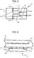
- FIG. 5 is a top view of the measurement unit
- FIG. 6 shows a state in which the measurement unit is located in contact with the living body
- FIG. 7 is a side view of the measurement unit in which a resin layer is provided on a substrate
- FIG. 8 shows a structure in which grooves are formed in the substrate and piezoelectric elements are embedded in the grooves
- FIG. 9 shows a structure in which the substrate and the piezoelectric elements are joined to each other by bumps
- FIG. 10 shows a structure of the measurement unit having the substrate in which gaps are produced by the grooves
- FIG. 11 shows a structure of the measurement unit having the substrate in which protrusions are formed
- FIG. 12 shows a structure of the measurement unit having the surface-processed substrate
- FIG. 13 shows a structure of the measurement unit having the piezoelectric elements in which the gaps are produced by the grooves
- FIG. 14 shows a structure of the measurement unit having the substrate in which the grooves are formed
- FIG. 15 shows a structure of the measurement unit having the divided substrates and a support
- FIG. 16 shows a structure of the measurement unit having the divided substrates and the support
- FIG. 17 shows a structure of the measurement unit having the divided substrates and the support
- FIG. 18 shows one embodiment of the measurement unit ( 4 );
- FIG. 19 shows one embodiment of the measurement unit ( 4 );
- FIG. 20 shows one embodiment of the measurement unit ( 4 );
- FIG. 21 shows one embodiment of the measurement unit ( 4 );
- FIG. 22 shows one embodiment of the support ( 81 );
- FIG. 23 shows one embodiment of the support ( 81 );
- FIG. 24 shows one embodiment of the support ( 81 )
- FIG. 25 shows one embodiment of the support ( 81 );
- FIG. 26 shows one embodiment of the support ( 81 );
- FIG. 27 shows one embodiment of the measurement unit ( 4 );
- FIG. 28 shows one embodiment of the measurement unit ( 4 );
- FIG. 29 shows one embodiment of the measurement unit ( 4 );
- FIG. 30 shows one embodiment of the measurement unit ( 4 );
- FIG. 31 shows the state in which the measurement unit is located in contact with the living body
- FIG. 32 shows an ultrasound diagnostic apparatus using conventional piezoelectric elements.
- a pulse detecting device of the present invention includes: a transmitting piezoelectric element for transmitting an ultrasound into a living body in response to an inputted drive signal; a receiving piezoelectric element for receiving an echo produced by reflecting the ultrasound by a blood flow of the living body; a substrate in which these piezoelectric elements are provided on one surface; a detection unit for detecting a pulse from the echo; and a feed portion, provided on the substrate, for applying the drive signal to the transmitting piezoelectric element, the substrate and the transmitting piezoelectric element being fixed onto the substrate in the feeding portion.
- both the transmitting piezoelectric element and the receiving piezoelectric element are located and fixed onto the substrate.
- these piezoelectric elements can be located with high precision as designed.
- the transmitting piezoelectric element Since the transmitting piezoelectric element is fixed in only the feed portion required for inputting a drive signal, the oscillation by the transmitting piezoelectric element does not easily propagate to the entire substrate. Thus, the possibility that the ultrasound is propagated into the substrate and directly received in the receiving piezoelectric element becomes lower. Therefore, the noise can be prevented and the detection sensitivity of the pulse can be improved.
- the possibility that the ultrasound is propagated into the substrate and directly received in the receiving piezoelectric element becomes further low.
- the sensitivity can be improved.
- the structure is obtained so as to lower the possibility that the ultrasound is propagated into the substrate and directly received in the receiving piezoelectric element.
- the sensitivity can be improved.
- a pulse detecting device is constructed such that a piezoelectric element for transmitting an ultrasound into a living body in response to an inputted drive electric signal or a piezoelectric element for receiving an echo produced by reflecting the ultrasound by a blood flow of the living body, is provided on a support or one surface of a substrate, and a space is produced in the side opposite to the living body side sandwiching the piezoelectric elements.
- the piezoelectric elements are located and fixed onto the support or the substrate.
- these piezoelectric elements can be located with high precision as designed. Therefore, according to the structure of the present invention, fluctuations in the quality are less likely to occur and the detection sensitivity of the pulse can be improved.
- An acoustic impedance of the substrate is set to be a value between that of the piezoelectric elements and that of the living body.
- a thickness of the substrate is set to be about a quarter of a wavelength of the ultrasound generated by the transmitting piezoelectric element.
- a resin layer is provided on a surface that is in contact with the living body. The details will be described in the following embodiments.
- a pulse detecting device according to Embodiment 1 of the present invention will be described in details with reference to FIGS. 1 to 6 .
- FIG. 1 is a side view showing a structure in an outer appearance of the pulse detecting device 1 to which the present invention is applied and FIG. 2 shows a state in which the pulse detecting device 1 shown in FIG. 1 is put on a living body (wrist) 2 .
- the pulse detecting device 1 is substantially constructed by a processing unit 3 , a measurement unit 4 , a band 5 , and a clip 6 .
- the pulse detecting device 1 is always portable by being put on the living body 2 .
- the processing unit 3 and the measurement unit 4 are attached to the band 5 , and thus these are put on the living body 2 (the broken line portion in the drawing) by the band 5 and the clip 6 .
- the measurement unit 4 is located in contact with a vicinity of the radial artery or the ulnar artery in the living body 2 (not shown).
- the processing unit 3 and the measurement unit 4 are connected with each other through wirings.
- a drive voltage signal is inputted from the processing unit 3 to the measurement unit 4 through the wirings.
- a voltage signal measured by the measurement unit 4 is inputted to the processing unit 3 .
- FIG. 3 is a block diagram showing an inner structure of the processing unit 3 and a connection state between the processing unit 3 and the measurement unit 4 .
- the processing unit 3 is substantially constructed by a processing arithmetic unit 31 , a driver circuit 32 , and a display unit 33 .
- the processing arithmetic unit 31 executes a processing program stored in a memory region (not shown) provided in the inner portion to perform various processings with respect to the detection of the pulse and causes the display unit 33 to display a processing result.
- the processing arithmetic unit 31 causes the driver circuit 32 to output a specific drive voltage signal to a transmitting piezoelectric element 41 (described later with respect to details) of the measurement unit 4 when the pulse is measured.
- the processing arithmetic unit 31 compares the frequency of the ultrasound emitted from the transmitting piezoelectric element 41 with that of the ultrasound that is received in a receiving piezoelectric element 42 and changed due to a Doppler effect of the blood flow, and thus detects the pulse.
- the driver circuit 32 outputs a specific drive voltage signal to the transmitting piezoelectric element 41 of the measurement unit 4 in response to instructions of the processing arithmetic unit 31 .
- the display unit 33 is composed of a liquid crystal display screen and the like and displays a pulse detection result and the like that are inputted from the processing arithmetic unit 31 .
- FIG. 4 is a schematic view showing a structure of the measurement unit 4 and FIG. 5 is a top view of the measurement unit 4 .
- the measurement unit 4 is substantially constructed by the transmitting piezoelectric element 41 , the receiving piezoelectric element 42 , and a substrate 43 .
- electrodes 45 a and 45 b and electrodes 46 a and 46 b are formed on both surfaces of the transmitting piezoelectric element 41 and the receiving piezoelectric element 42 in a thickness direction.
- electrodes 47 a and 47 b and top electrodes 60 a and 60 b are formed on one surface 43 a of the substrate 43 .
- the electrodes 45 a and 46 a are electrically connected with the top electrodes 60 a and 60 b through wirings 61 .
- a material of the substrate 43 a material resisting the propagation of the ultrasound is suitable.
- the electrodes 45 a , 45 b , 46 a , 46 b , 47 a , 47 b , 48 a , 48 b , 60 a , and 60 b are made from a film of metal such as Au or Pt and formed by a method such as evaporation.
- the wirings 61 are formed by wire bonding using an Au wire or the like.
- the transmitting piezoelectric element 41 is located and fixed on one surface 43 a of the substrate 43 so as to be overlapped with the electrode 47 a in a fix portion 62 .
- the receiving piezoelectric element 42 is located and fixed on one surface 43 a so as to be overlapped with the electrode 47 b in a fix portion 62 .
- the transmitting piezoelectric element 41 and the receiving piezoelectric element 42 the same piezoelectric element may be used. Shapes of these piezoelectric elements 41 and 42 are arbitrary and piezoelectric elements with different shapes may be used for transmitting and receiving. A plurality of transmitting piezoelectric elements and a plurality of receiving piezoelectric elements may be arranged.
- a PZT having a thickness of 0.2 mm (resonance frequency is 9.6 MHz) and an outer size of 2 ⁇ 4 mm is used as the transmitting piezoelectric element and the receiving piezoelectric element.
- a glass substrate having a thickness of 0.5 mm and an outer size of 10 ⁇ 11 mm is used as the transmitting piezoelectric element and the receiving piezoelectric element.
- the electrodes 45 a and 45 b are connected with the driver circuit 32 of the processing unit 3 through the electrodes 47 a and 60 a by wirings.
- the transmitting piezoelectric element 41 is excited to generate an ultrasound with a specific frequency.
- the ultrasound is transmitted into the living body (see “ 2 ” in FIG. 6 ).
- the transmitting piezoelectric element 41 is excited at 9.6 MHz.
- the electrodes 46 a and 46 b are connected with the processing arithmetic unit 31 of the processing unit 3 through the electrodes 47 b and 60 b by wirings.
- the receiving piezoelectric element 42 converts the received ultrasound into a voltage signal and outputs it to the processing arithmetic unit 31 of the processing unit 3 .
- FIG. 6 shows a location relation between the measurement unit 4 of the pulse detecting device according to this embodiment and the living body 2 .
- the electrodes 45 a , 45 b , 46 a , 46 b , 60 a , and 60 b and the wirings 61 are omitted.
- the processing arithmetic unit 31 shown in FIG. 3 causes the driver circuit 32 to output the specific drive voltage signal to the electrodes 45 a and 45 b (see FIG. 5 ) of the transmitting piezoelectric element 41 .
- the transmitting piezoelectric element 41 is excited in response to the drive voltage signal input to the electrodes 45 a and 45 b to generate the ultrasound, and then transmits the ultrasound into the living body 2 (see FIG. 6 ).
- the ultrasound transmitted into the living body 2 is reflected by a blood flow 2 a and received in the receiving piezoelectric element 42 of the measurement unit 4 .
- the receiving piezoelectric element 42 converts the received ultrasound into the voltage signal and outputs it from the electrodes 46 a and 46 b (see FIG. 5 ) to the processing arithmetic unit 31 .
- the processing arithmetic unit 31 compares the frequency of the ultrasound generated by the transmitting piezoelectric element 41 with that of the ultrasound that is received in the receiving piezoelectric element 42 and changed due to a Doppler effect of the blood flow, and thus detects the pulse of the living body. Then, the processing arithmetic unit 31 causes the display unit 33 to display a pulse detection result.
- the pulse detecting device 1 measures the pulse of the living body and displays its measurement result.
- metal such as aluminum or Au is vacuum-evaporated to form the electrodes 45 a , 45 b , 46 a , and 46 b . Outer shapes are cut by dicing or the like.
- metal such as aluminum or Au is vacuum-evaporated to form electrodes on one surface 43 a and then a thin film process such as etching is performed to form the electrodes 47 a , 47 b , 60 a , and 60 b on one surface 43 a.
- the electrodes 45 a and 45 b and the electrodes 47 a and 47 b are fixed in the fix portions 62 by using a conductive adhesive or the like.
- the transmitting piezoelectric element 41 and the receiving piezoelectric element 42 are fixed onto the substrate 43 .
- the electrodes 47 a and 60 a are connected with the driver circuit 32 of the processing unit 3 of FIG. 3 through wirings (not shown).
- the electrodes 47 b and 60 b are connected with the processing arithmetic unit 31 .
- the transmitting piezoelectric element 41 and the receiving piezoelectric element 42 are located on the substrate 43 .
- the transmitting piezoelectric element 41 and the receiving piezoelectric element 42 can be located on the substrate 43 with high precision, the pulse detecting device 1 in which the quality of the measurement unit 4 is stable with little fluctuation can be provided. Also, since the piezoelectric elements are fixed onto the substrate 43 only in the fix portions 62 of FIG. 5 , the ultrasound is unlikely to directly propagate to the substrate 43 and the noise is decreased. Thus, the detection sensitivity of the pulse can be improved. According to this embodiment, in the case where the sizes of the transmitting piezoelectric element and the receiving piezoelectric element are 2 ⁇ 4 mm and the size of the substrate is 10 ⁇ 11 mm, the areas of the fix portions 62 are set to be 0.5 mm ⁇ 0.5 mm.
- the transmitting piezoelectric element 41 and the receiving piezoelectric element 42 are fixed onto the entire surface of the substrate 43 by using a conductive adhesive or the like, when a burst signal (five sine waves) with ⁇ 5 V and 9.5 MHz is inputted to the transmitting piezoelectric element 41 , in a state in which the measurement of the pulse is not being performed (non-measurement state), a burst signal with 0.8% of the amplitude of the inputted burst signal is received in the receiving piezoelectric element 42 .
- an amplitude of a burst signal detected in the receiving piezoelectric element is decreased to 0.02% of the amplitude of the inputted burst signal.
- a reflection strength of the ultrasound for a Cu plate provided in silicon oil was measured.
- the reflection strength is 0.2%.
- the reflection strength becomes 0.6% that is about three times larger than the case of the fixation in the entire surface. Therefore, the detection sensitivity of the pulse is improved.
- the piezoelectric elements are not embedded in the resin for the fixation as was conventionally the case.
- electrodes can be easily formed on both surfaces of the transmitting piezoelectric element 41 and the receiving piezoelectric element 42 , and can be easily led from the respective piezoelectric elements.
- the pulse detecting device of this embodiment generally measures the pulse and displays its measurement-result, and further can measure the pulse wave.
- the structure is used in the pulse detecting device 1 such that the processing unit 3 and the measurement unit 4 are separated from each other.
- these units may be structured as one module.
- the number of parts in the pulse detecting device 1 is reduced and the increase in the manufacturing cost can be suppressed.
- wirings between the processing unit 3 and measurement unit 4 can be simplified.
- the structure may be used such that a communication unit and the like are provided in the processing unit 3 and a pulse measurement result is transmitted to a management system in a hospital. Thus, a state of a patient on which the pulse detecting device 1 is put can be always grasped.
- an excitation frequency of the piezoelectric element is set to be 9.6 MHz.
- an excitation frequency of the piezoelectric element is set to be 9.6 MHz.
- FIG. 7 is a side view of the measurement unit 4 in the pulse detecting device of this embodiment, and the electrodes 45 a , 45 b , 60 a , 60 b , 46 a , 46 b , 47 a , and 47 b and the wirings 61 are omitted.
- the processing unit the band, the clip, the piezoelectric elements, and the substrate, the same ones as in Embodiment 1 are used.
- FIG. 7 shows a structure of the measurement unit 4 in which a resin layer 49 is provided on one surface 43 a of the substrate 43 .
- the resin layer 49 is formed on one surface 43 a of the substrate 43 .
- the resin layer 49 is made of epoxy based resin or silicon based resin.
- the resin layer 49 has an effect for the protection of the transmitting piezoelectric element 41 and the receiving piezoelectric element 42 , an effect for the insulation of the electrodes 45 a , 45 b , 60 a , 60 b , 46 a , 46 b , 47 a , and 47 b and the wirings 61 , and an effect for the propagation of the ultrasound between the living body and the respective piezoelectric elements 41 and 42 with high efficiency.
- the acoustic impedance of the resin layer 49 is set to be a value between the acoustic impedance Zl of the living body and the acoustic impedance Zc of the piezoelectric element.
- the acoustic impedance is a value indicating the ease with which an acoustic wave propagates. This value is changed by Young's modulus and a density.
- Zm ( Zc ⁇ ZL) 1/2 (1).
- epoxy based resin having an acoustic impedance of about 3 M (N ⁇ sec/m 3 ) is used for the substrate 43 .
- the thickness of the resin layer 49 in a substrate thickness direction is as thin as possible. In the structure as this embodiment, it is suitable to be 100 ⁇ m or thinner.
- the resin 49 is applied onto the substrate 43 by a spin coat or a bar coat and then cured by heating or ultraviolet radiation, the resin layer 49 can be uniformly located with a constant thickness.
- the resin layer made of epoxy based resin may be formed on one surface 43 a of the substrate 43 and then the resin layer made of silicon based resin may be formed thereon to obtain a two-layer resin layer.
- the reflection and the attenuation of the ultrasound can be prevented.
- the silicon based resin When the silicon based resin is used for the resin layer 49 , since the silicon based resin is soft, the adhesiveness between the substrate 43 and the living body is improved by the resin layer 49 . Thus, an air layer present between the living body and the substrate 43 can be decreased and the attenuation in an oscillation of the ultrasound due to the air layer can be suppressed.
- the silicon based resin has high compatibility with the living body. Thus, even if this resin is in closely contact with the skin, the influence to the skin is small.
- FIG. 8 is a side view of the measurement unit 4 in the pulse detecting device of the present invention and the wirings 61 and the electrodes 60 a and 60 b are omitted.
- the processing unit the band, the clip, the piezoelectric elements, and the substrate, the same ones as in Embodiment 1 are used.
- grooves are formed in the substrate 43 , the electrodes 47 a and 47 b are formed in the grooves, the transmitting piezoelectric element 41 and the receiving piezoelectric element 42 are located in the grooves, and the resin layer 49 is attached onto the substrate 43 . Therefore, when the piezoelectric elements are embedded in the grooves, as described above, the unevenness due to the piezoelectric elements is not produced and thus the resin layer 49 can be formed with further uniformity.
- FIG. 9 is a side view of the measurement unit 4 in the pulse detecting device of the present invention.
- the band, the clip, the piezoelectric elements, and the substrate the same ones as in Embodiment 1 are used.
- the electrodes 60 a and 60 b and the wirings 61 are omitted.
- bumps 71 made of solder or the like are formed on the electrodes 47 a and 47 b .
- the transmitting piezoelectric element 41 and the receiving piezoelectric element 42 are fixed onto the electrodes 47 a and 47 b by the bumps 71 .
- gaps 70 are produced between the transmitting piezoelectric element 41 and the electrode 47 a and between the receiving piezoelectric element 42 and the electrode 47 b.
- the bumps 71 are formed using the solder and the height of the bumps 71 is set to be 10 ⁇ m.
- An air layer has an extremely high attenuation factor for the ultrasound. Therefore, when the gaps 70 as the air layer are present, the possibility that the ultrasound is propagated into the substrate 43 and directly received in the receiving piezoelectric element 42 becomes lower. Thus, the generation of noise in the pulse measurement can be prevented.
- the bumps are formed for both the transmitting piezoelectric element 41 and the receiving piezoelectric element 42 . Even when the bumps are formed for either the transmitting piezoelectric element 41 or the receiving piezoelectric element 42 , the same effect can be obtained.
- the resin layer may be provided as in Embodiment 2.
- FIG. 10 is a side view of the measurement unit 4 in the pulse detecting device of this embodiment.
- the band, the clip, the piezoelectric elements, and the substrate the same ones as in Embodiment 1 are used.
- the electrodes 60 a and 60 b and the wirings 61 are omitted.
- the pulse detecting device of this embodiment is constructed by providing the gaps 70 between the substrate 43 and the transmitting piezoelectric element 41 and the receiving piezoelectric element 42 .
- the gaps 70 are produced on the substrate 43 .
- the transmitting piezoelectric element 41 and the electrode 47 a and the receiving piezoelectric element 42 and the electrode 47 b are located sandwiching the gaps 70 .
- An air layer has an extremely high attenuation factor for the ultrasound. Therefore, by the gaps 70 , the possibility that the ultrasound is propagated into the substrate 43 and directly received in the receiving piezoelectric element 42 becomes lower. Thus, the generation of noise in the pulse measurement can be prevented. Further, the detection sensitivity can be improved.
- a distance propagation characteristic of the ultrasound an odd multiple of a quarter of a wavelength ⁇ , which corresponds to the peak of a wave, is preferable, in particular, about a quarter is suitable.
- the ultrasound is largely attenuated in a gas, a liquid, or a solid.
- the thickness (depth) of the gaps 70 corresponds to the wavelength ⁇ of the ultrasound or more, the ultrasound is sufficiently attenuated and thus a preferable characteristic is obtained.
- the thickness (depth) of the gaps 70 is suitable to be 0.2 mm or more.
- the substrate 43 is diced to produce the gaps 70 .
- other processing method may be used.
- the depth of the gaps 70 is set to be about 0.2 mm.
- the resin layer may be provided as in Embodiment 2.
- FIG. 11 is a side view of the measurement unit 4 in the pulse detecting device of this embodiment and the electrodes 47 a , 47 b , 60 a , and 60 b and the wirings 61 are omitted.
- the band, the clip, the piezoelectric elements, and the substrate the same ones as in Embodiment 1 are used.
- protrusions 72 are provided for the transmitting piezoelectric element 41 and the receiving piezoelectric element 42 on the substrate 43 . Since the transmitting piezoelectric element 41 and the receiving piezoelectric element 42 are fixed by only the protrusions 72 , the ultrasound emitted from the transmitting piezoelectric element 41 is unlikely to directly propagate to the receiving piezoelectric element 42 . Thus, the generation of noise in the pulse measurement can be prevented.
- the protrusions 72 are formed by plating metal such as copper on the substrate 43 .
- the protrusions 72 may be formed on the substrate 43 by dicing or the like.
- the resin layer may be provided as in Embodiment 2.
- FIG. 12 is a side view of the measurement unit 4 in the pulse detecting device of this embodiment and the electrodes 60 a and 60 b and the wirings 61 are omitted.
- the band, the clip, the processing unit, the piezoelectric elements, and the substrate the same ones as in Embodiment 1 are used.
- a surface processing is made for one surface 43 a of the substrate 43 with a fixed roughness by grinding or the like. That is, electrodes (not shown) are provided on one surface 43 a of the substrate 43 . The surface processing is made with a certain roughness by grinding or the like. Then, the transmitting piezoelectric element 41 and the receiving piezoelectric element 42 are fixed onto one surface 43 a by using a conductive adhesive or the like. Thus, the transmitting piezoelectric element 41 and the receiving piezoelectric element 42 are in contact with an extremely limited area of the substrate 43 through the electrodes 45 b and 46 b . Therefore, the ultrasound emitted from the transmitting piezoelectric element 41 is unlikely to directly propagate to the receiving piezoelectric element 42 . As a result, the generation of noise in the pulse measurement can be prevented. Further, the detection sensitivity can be improved.
- FIG. 13 is a side view of the measurement unit 4 in the pulse detecting device according to Embodiment 8 of the present invention and the electrodes 60 a and 60 b and the wirings 61 are omitted.
- the processing unit, the clip, and the substrate the same ones as in Embodiment 1 are used.
- grooves are formed in the sides of the electrodes 45 b and 46 b in the transmitting piezoelectric element 41 and the receiving piezoelectric element 42 .
- the transmitting piezoelectric element 41 and the receiving piezoelectric element 42 are fixed onto the electrodes 47 a and 47 b through the gaps 70 .
- the gaps 70 are produced by forming the grooves in the sides of the electrodes 45 b and 46 b in the transmitting piezoelectric element 41 and the receiving piezoelectric element 42 by dicing.
- An air layer has an extremely high attenuation factor for the ultrasound.
- the transmitting piezoelectric element 41 and the receiving piezoelectric element 42 are fixed onto the substrate 43 through the gaps 70 . Therefore, the ultrasound is attenuated by the gaps 70 and the ultrasound emitted from the transmitting piezoelectric element 41 is unlikely to directly propagate to the receiving piezoelectric element 42 . Thus, the generation of noise in the pulse measurement can be prevented.
- the resin layer may be provided as in Embodiment 2.
- the resin layer may be provided as in Embodiment 2. Further, a polarization processing may be made for only portions of the transmitting piezoelectric element 41 and the receiving piezoelectric element 42 , which correspond to the gaps 70 in a piezoelectric element thickness direction. In this case, the above effect can be further improved.
- FIG. 14 is a side (perspective) view of the measurement unit 4 and the electrodes 60 a and 60 b and the wirings 61 are omitted. With respect to materials and shapes of the piezoelectric elements and the substrate, the same ones as in Embodiment 1 are used.
- a groove 50 a is formed in the substrate 43 . Then, the electrodes 45 b and 46 b and the electrodes 47 a and 47 b of the transmitting piezoelectric element 41 and the receiving piezoelectric element 42 are fixed sandwiching the groove 50 a .
- the ultrasound emitted from the transmitting piezoelectric element 41 is reflected and attenuated by the groove 50 a of the substrate 43 . Therefore, the possibility that the ultrasound is propagated into a transmitting and receiving substrate 50 and directly received in the receiving piezoelectric element 42 becomes lower. Thus, the generation of noise in the pulse measurement can be prevented.
- the groove 50 a is processed in the substrate 43 by dicing.
- the resin layer may be provided as in Embodiment 2.
- FIG. 15 is a perspective view showing a schematic structure of the measurement unit 4 in the pulse detecting device according to this embodiment.
- the band, the clip, the processing unit, and the piezoelectric elements the same ones as in Embodiment 1 are used.
- the substrate 43 is divided into two spaced-apart substrate sections and the transmitting piezoelectric element 41 and the receiving piezoelectric element 42 are disposed on and fixed to top surfaces of respective ones of the substrate sections.
- a support or support member 81 is attached onto the bottom surfaces of the substrate sections of the divided substrate 43 .
- the support 81 has a concave shape defined by two side wall portions 83 , 83 interconnected by a base portion.
- a gap 80 is produced between the substrate 43 and the support 81 . Even when the substrate 43 is divided as shown in FIG. 15 , the substrate 43 can be easily provided with high precision. In addition, the transmitting strength and the receiving strength of the ultrasound can be improved.
- the cross-sectional area of the gap 80 which corresponds to an opening portion in a concave portion 82 of the support 81 (L X M in FIG. 22 ) is smaller than the total area of a transmit plane of the transmitting piezoelectric element 41 and a receive plane of the receiving piezoelectric element 42 , the ultrasound propagates through side wall portions 83 of the support 81 . Therefore, it is desirable that the area of the concave portion 82 is larger (wider) than the total area of the transmitting piezoelectric element 41 and the receiving piezoelectric element 42 .
- the ultrasound generated by the transmitting piezoelectric element 41 is propagated to the substrate 43 , since the gap 80 is present between the substrate 43 and the support 81 , the ultrasound is attenuated and thus is not propagated to the support 81 . Therefore, the ultrasound emitted from the transmitting piezoelectric element 41 is unlikely to directly propagate to the receiving piezoelectric element 42 . As a result, the generation of noise in the pulse measurement can be prevented. Further, the detection sensitivity can be improved.
- acrylic is used as the support 81 .
- the support 81 is formed using a porous material in which the ultrasound is easily attenuated, or the like, the ultrasound emitted from the transmitting piezoelectric element 41 is unlikely to directly propagate to the receiving piezoelectric element 42 . Thus, the generation of noise in the pulse measurement can be prevented.
- the resin layer may be provided as in Embodiment 2.
- FIG. 16 is a perspective view showing a schematic structure of the measurement unit 4 in the pulse detecting device according to this embodiment.
- the processing unit, the clip, the piezoelectric elements, and the substrate the same ones as in Embodiment 1 are used.
- the substrate 43 is divided into two spaced-apart substrate sections and the transmitting piezoelectric element 41 and the receiving piezoelectric element 42 are disposed on and fixed to top surfaces of the respective substrate sections.
- a support or support member 89 is attached onto the bottom surface of the substrate 43 through columnar projections in the form of posts 83 . Even when the substrate 43 is divided as shown in FIG. 16 , the substrate 43 can be easily provided with high precision. In addition, the transmitting strength and the receiving strength of the ultrasound can be improved.
- the support 89 is attached onto the substrate 43 through the posts 83 . Even if the ultrasound generated by the transmitting piezoelectric element 41 is propagated to the substrate 43 , since the gap 80 is present between the substrate 43 and the support 89 , the ultrasound is attenuated and thus is not propagated to the support 89 . Therefore, the ultrasound emitted from the transmitting piezoelectric element 41 is unlikely to directly propagate to the receiving piezoelectric element 42 . As a result, the generation of noise in the pulse measurement can be prevented. Further, the detection sensitivity can be improved.
- acrylic is used as the support 89 .
- the support 89 is formed using a porous material in which the ultrasound is easily attenuated, or the like, the ultrasound emitted from the transmitting piezoelectric element 41 is unlikely to directly propagate to the receiving piezoelectric element 42 . Thus, the generation of noise in the pulse measurement can be prevented.
- a resin layer may be provided as in Embodiment 2.
- FIG. 17 is a side view of the measurement unit 4 in the pulse detecting device according to this embodiment.
- the processing unit, the clip, the piezoelectric elements, and the substrate the same ones as in Embodiment 1 are used.
- the electrodes 45 a , 45 b , 46 a , 46 b , 60 a and 60 b and the wirings 61 are omitted.
- the substrate 43 is divided into the side of the transmitting piezoelectric element 41 and the side of the receiving piezoelectric element 42 .
- the support 89 is attached onto the other surface of the substrate 43 .
- the resin layer 49 is divided into the side of the transmitting piezoelectric element 41 and the side of the receiving piezoelectric element 42 .
- the support 81 When a material such as a porous material (such as ceramic) or rubber, in which the ultrasound is easily attenuated, is used as the support 81 , it can prevent the ultrasound from propagating from the transmitting piezoelectric element 41 to the receiving piezoelectric element 42 through the support 81 .
- a material such as a porous material (such as ceramic) or rubber, in which the ultrasound is easily attenuated
- FIG. 1 A side view showing a structure in an outer appearance of the pulse detecting device 1 according to the present invention is shown in FIG. 1 .
- FIG. 2 a state in which the pulse detecting device 1 shown in FIG. 1 is put on the living body (wrist) 2 is shown in FIG. 2 .
- the pulse detecting device 1 is substantially constructed by the processing unit 3 , the measurement unit 4 , the band 5 , and the clip 6 .
- the pulse detecting device 1 is always portable by being put on the living body 2 .
- the processing unit 3 and the measurement unit 4 are attached to the band 5 , and thus these are put on the living body 2 (the broken line portion in FIG. 1 ) by the band 5 and the clip 6 .
- the measurement unit 4 is located in contact with the vicinity of the radial artery or the ulnar artery in the living body 2 (not shown).
- the processing unit 3 and the measurement unit 4 are connected with each other through wirings.
- a drive voltage signal is inputted from the processing unit 3 to the measurement unit 4 through the wirings.
- a voltage signal measured by the measurement unit 4 is inputted to the processing unit 3 .
- FIG. 3 A block diagram showing an inner structure of the processing unit 3 of the pulse detecting device and a connection state between the processing unit 3 and the measurement unit 4 are shown in FIG. 3 .
- the processing unit 3 is substantially constructed by the processing arithmetic unit 31 , the driver circuit 32 , and the display unit 33 .
- the processing arithmetic unit 31 executes a processing program stored in a memory region (not shown) provided in the inner portion to perform various processings with respect to the detection of the pulse and causes the display unit 33 to display the processing result. Also, the processing arithmetic unit 31 causes the driver circuit 32 to output a specific drive voltage signal to the transmitting piezoelectric element 41 (described later with respect to details) of the measurement unit 4 when the pulse is measured. Further, the processing arithmetic unit 31 compares the frequency of the ultrasound emitted from the transmitting piezoelectric element 41 with that of the ultrasound that is received in the receiving piezoelectric element 42 and changed due to a Doppler effect of blood flow, and thus detects the pulse.
- the driver circuit 32 outputs a specific drive voltage signal to the transmitting piezoelectric element 41 of the measurement unit 4 in response to instructions of the processing arithmetic unit 31 .
- the display unit 33 is composed of a liquid crystal display screen and the like, and displays a pulse detection result and the like that are inputted from the processing arithmetic unit 31 .
- FIG. 18 a cross sectional view of the measurement unit 4 of the pulse detecting device 1 is shown in FIG. 18 .
- the transmitting piezoelectric element 41 and the receiving piezoelectric element 42 are joined onto a receiving and transmitting substrate 44 .
- the receiving and transmitting substrate 44 is supported by the support 81 .
- a space 80 can be produced over one surface of the respective piezoelectric elements.
- the transmitting piezoelectric element 41 and the receiving piezoelectric element 42 can propagate the ultrasound only in ultrasound transmitting and receiving directions.
- the transmitting piezoelectric element 41 is electrically connected with the driver circuit 32 of the processing unit 3 through the wirings.
- the transmitting piezoelectric element 41 is excited to generate the ultrasound with a specific frequency.
- the generated ultrasound is transmitted into the living body (“ 2 ” in FIG. 31 ).
- the receiving piezoelectric element 42 is electrically connected with the processing arithmetic unit 31 of the processing unit 3 through the wirings.
- the receiving piezoelectric element 42 converts the received ultrasound into a voltage signal and outputs it to the processing arithmetic unit 31 of the processing unit 3 .
- the transmitting piezoelectric element 41 and the receiving piezoelectric element 42 are located on one surface 43 a of the transmitting and receiving substrate 44 .
- the other surface 43 b thereof is in contact with the living body and made from a glass substrate or the like.
- the acoustic impedance of the transmitting and receiving substrate 44 is set to be a value between the acoustic impedance ZL of the living body and the acoustic impedance Zc of the piezoelectric element.
- the acoustic impedance is a value indicating the ease of propagating an acoustic wave. This value is changed by Young's modulus and a density.
- Zm ( Zc ⁇ ZL ) 1/2 (1).
- a glass substrate having an acoustic impedance of about 10 M (N ⁇ sec/m 3 ) is used as the transmitting and receiving substrate 44 .
- the thickness of the transmitting and receiving substrate 44 is an important factor.
- the thickness of the transmitting and receiving substrate 44 is not suitable, as the above acoustic impedance, the ultrasound is reflected in the transmitting and receiving substrate 44 and thus is not propagated with high efficiency.
- the thickness of the transmitting and receiving substrate 44 is set to be about a quarter of the wavelength in the frequency of the ultrasound which the transmitting and receiving substrate 44 propagates.
- the thickness of the transmitting and receiving substrate 44 is set to be about 140 ⁇ m.
- a resin layer 48 is formed on a surface of the transmitting and receiving substrate 44 , which is opposite to a piezoelectric element forming surface, that is, a surface that is in contact with the living body.
- the resin layer 48 is made of epoxy based resin or silicon based resin. A property of a contact surface (the other surface 43 b ) of the transmitting and receiving substrate 44 to the living body is different depending on a kind of resin to be used.
- the acoustic impedance of the epoxy based resin is the value between the acoustic impedance of the transmitting and receiving substrate 44 and that of the living body.
- the reflection of the ultrasound, which is produced in the interface between the living body and the transmitting and receiving substrate 44 can be further reduced. Therefore, the ultrasound can be propagated with high efficiency between the living body and the substrate 44 .
- an ideal acoustic impedance of the resin layer 48 is calculated by the same equation as the above equation (1).
- the silicon based resin when used for the resin layer 48 , since the silicon based resin is soft, the adhesiveness between the transmitting and receiving substrate 44 and the living body is improved by the resin layer 48 . Thus, an air layer present between the living body and the transmitting and receiving substrate 44 can be decreased and the attenuation in the oscillation of the ultrasound due to the air layer can be suppressed.
- the silicon based resin has high compatibility with the living body. Thus, even if this resin is in close contact with the skin, the influence to the skin is small.
- the resin layer made of the epoxy based resin is formed on the other surface of the transmitting and receiving substrate 44 and then the resin layer made of the silicon based resin may be formed thereon to obtain two-layer resin layers.
- the reflection and the attenuation of the ultrasound can be prevented.
- the processing arithmetic unit 31 shown in FIG. 3 causes the driver circuit 32 to output the specific drive voltage signal to the transmitting piezoelectric element 41 .
- the transmitting piezoelectric element 41 is excited in response to the inputted drive voltage signal to generate an ultrasound, and then transmits the ultrasound into the living body 2 through the transmitting and receiving substrate 44 .
- the ultrasound transmitted into the living body 2 is reflected by the blood flow 2 a and received in the receiving piezoelectric element 42 of the measurement unit 4 .
- the receiving piezoelectric element 42 converts the received ultrasound into the voltage signal and outputs it to the processing arithmetic unit 31 .
- the processing arithmetic unit 31 compares the frequency of the ultrasound generated by the transmitting piezoelectric element 41 with that of the ultrasound that is received in the receiving piezoelectric element 42 and changed due to a Doppler effect of the blood flow, and thus detects the pulse of the living body. Then, the processing arithmetic unit 31 causes the display unit 33 to display the pulse detection result. Thus, the pulse detecting device 1 measures the pulse of the living body and displays its measurement result.
- the transmitting piezoelectric element 41 and the receiving piezoelectric element 42 can be located on the transmitting and receiving substrate 44 with high precision, the quality of the measurement unit 4 is stable, and the pulse detecting device 1 in which the quality does not vary can be provided. In addition, the detection sensitivity of the pulse can be improved.
- the pulse detecting device 1 since the pulse detecting device 1 has the support portion, the strength of the pulse detecting device 1 is increased. Thus, the durability of the pulse detecting device 1 is improved.
- the pulse detecting device 1 of this embodiment generally measures the pulse and displays its measurement result, and it further can measure the pulse wave.
- the detail portion of the pulse detecting device of the present invention is not limited to the contents of the above embodiment, and various modifications may be naturally made in the scope not departing from the gist of the present invention.
- the transmitting piezoelectric element 41 and the receiving piezoelectric element 42 are joined onto the transmitting and receiving substrate 44 by metallic bond.
- this joining may be made by hydrogen bond.
- water is ionized using an ion source to produce hydroxide ions OH ⁇ .
- the transmitting and receiving substrate 44 and the respective piezoelectric elements 41 and 42 are pressed to each other to make the above joining.
- a hydrophilic group is formed on the transmitting and receiving substrate 44 , and then the respective piezoelectric elements 41 and 42 may be joined onto the transmitting and receiving substrate 44 by the hydrogen bond using the hydrophilic group.
- these units may be structured as one module.
- the number of parts in the pulse detecting device 1 is reduced and the increase in the manufacturing cost can be suppressed.
- wirings between the processing unit 3 and measurement unit 4 can be simplified.
- the structure may be used such that a communication unit and the like are provided in the processing unit 3 and a pulse measurement result is transmitted to a management system in a hospital. Thus, a state of a patient on which the pulse detecting device 1 is put can be always grasped.
- FIG. 18 A modification example of the structure of the measurement unit 4 shown in FIG. 18 will be described with reference to FIGS. 19 to 21 . Note that, in the description below, portions with the same structure as in the measurement unit 4 shown in FIG. 18 are referred with the same reference. Therefore, the duplicate explanation is omitted here.
- FIG. 19 shows a structure of the measurement unit 4 in which the transmitting piezoelectric element 41 and the receiving piezoelectric element 42 are located sandwiching a groove 43 c formed in the transmitting and receiving substrate 44 .
- the groove 43 c is formed in the transmitting and receiving substrate 44 .
- the transmitting piezoelectric element 41 and the receiving piezoelectric element 42 are located sandwiching the groove 43 c.
- the ultrasound emitted from the transmitting piezoelectric element 41 at the time of pulse detection is reflected and attenuated by the groove 43 c of the transmitting and receiving substrate 44 .
- the possibility that the ultrasound is propagated into the transmitting and receiving substrate 44 and directly received in the receiving piezoelectric element 42 becomes lower.
- the generation of noise in the pulse measurement can be prevented.
- the detection sensitivity can be improved.
- a shape of the groove 43 c is arbitrary.
- a cross sectional shape of the groove 43 c may be an inverted triangle.
- FIG. 20 shows a structure of a measurement unit 4 in which the transmitting piezoelectric element 41 and the receiving piezoelectric element 42 are located on divided transmitting and receiving substrates or substrate sections 44 and 45 .
- the transmitting and receiving substrate 44 FIG. 18
- the transmitting and receiving substrate 44 FIG. 18
- the transmitting piezoelectric element 41 is located on the transmitting substrate 44
- the receiving piezoelectric element 42 is located on the receiving substrate 45 .
- the ultrasound emitted from the transmitting piezoelectric element 41 at the time of pulse detection is not directly propagated to the receiving piezoelectric element 42 .
- the generation of noise in the pulse measurement can be prevented.
- FIG. 21 shows a structure of a measurement unit 4 in which a transmitting substrate 44 and a receiving substrate 45 , which are obtained by dividing, have taper shapes.
- the transmitting and transmitiing substrate 44 FIG. 18
- the transmitting piezoelectric element 41 is located on one surface (bottom surface) 44 a of the transmitting substrate 44
- the receiving piezoelectric element 42 is located on one surface (bottom surface) 45 a of the receiving substrate 45 .
- the other (top) surface 44 b of the transmitting and receiving substrate 44 and the other (top) surface 45 b of the transmitting and receiving substrate 45 have taper shapes and are inclined relative to one another less than 180 degrees.
- the taper shapes are formed along the direction of the blood flow of the living body and such that outside portions of the respective transmitting and receiving substrates 44 and 45 are thicker than their inside portions. Therefore, the ultrasound emitted from the transmitting piezoelectric element 41 can be easily to focused near the blood flow of the living body. Thus, the ultrasound reflected by the blood flow of the living body can be received in the receiving piezoelectric element 42 with high efficiency.
- the structure of the support is not limited to the support 81 ( FIG. 22 ) with the concave shape as shown in FIGS. 18 to 21 .
- a support with a box shape as shown in FIG. 23 may also be used. When the support with the box shape shown in FIG. 23 is used, the pulse detecting device with high durability can be obtained.
- the support (support member) 81 may be formed with columnar projections in a comb teeth shape.
- the area for holding the substrate is reduced, the amount of leakage of the ultrasound from the transmitting side to the receiving side is decreased, and the amount of noise is further decreased.
- the pulse detecting device with higher performance can be obtained.
- the projections may be conical prolections having tips that form acute angles, whereby the pulse detection device in which the amount of noise is further decreased can be obtained.
- a metal material, an organic material, an inorganic material, or composite material of these is used as a material of the support 81 .
- ceramics is used for the support, since the ceramics is hard, the strength of the pulse detecting device is increased.
- plastic is used for the support, it is suitable for mass production, and thus the cost is reduced. In particular, when the plastic is used, the cost is reduced without a concern for a shape by an injection molding or the like.
- metal is used for the support 81 , the support can be precisely processed. Therefore, when plastic and metal are used for a support as shown in FIG. 26 , the pulse detecting device with low cost and low noise can be obtained.
- a porous material such as ceramics or sponge is used, since the ultrasound is not propagated, the noise is reduced and thus the performance is improved.
- FIG. 27 is a side view of a measurement unit 4 in the pulse detecting device of this embodiment, and the electrodes 60 a and 60 b and the wirings 61 are omitted.
- the band, the clip, the processing unit, the piezoelectric elements, and the substrate the same ones as in Embodiment 1 are used.
- FIG. 27 shows the case where respective conductive rubbers as ultrasound attenuation layers 73 are located between the electrodes 47 a and the transmitting piezoelectric element 41 and between the electrode 47 b and the receiving piezoelectric element 42 .
- a frequency of the ultrasound to be used is about 1 MHz to 10 MHz.
- an elastic material such as rubber has a high attenuation factor in the above frequency band, and thus can be used as an ultrasound attenuation material. Therefore, as this embodiment, when the respective conductive rubbers are located between the electrodes 47 a and the transmitting piezoelectric element 41 and between the electrode 47 b and the receiving piezoelectric element 42 , predetermined electrical signals can be applied to the transmitting piezoelectric element 41 and the receiving piezoelectric element 42 . In addition, the possibility that the ultrasound is propagated into the substrate 43 and directly received in the receiving piezoelectric element 42 can be lowered. As a result, since the strength of the ultrasound transmitted into the living body is increased, the detection sensitivity can be improved.
- the ultrasound attenuation layer 73 is divided between the transmitting piezoelectric element 41 and the receiving piezoelectric element 42 . If the ultrasound attenuation layer 73 is not divided, the ultrasound from the transmitting piezoelectric element 41 easily propagates to the receiving piezoelectric element 42 through the ultrasound attenuation layer 73 . This causes the reduction in the detection sensitivity.
- FIG. 28 is a side view of a measurement unit 4 in the pulse detecting device of this embodiment.
- the processing unit, the clip, the piezoelectric elements, and the substrate the same ones as in Embodiment 1 are used.
- the electrodes 45 a , 45 b , 46 a , 46 b , 60 a , and 60 b and the wirings 61 are omitted.
- FIG. 28 shows a structure in which the transmitting piezoelectric element 41 and the receiving piezoelectric element 42 are located on the divided substrates 43 and the substrates 43 are fixed onto the support 81 through ultrasound attenuation layers 75 .
- epoxy resin containing tungsten powder As a material of the ultrasound attenuation layers 75 , as described in Embodiment 3, epoxy resin containing tungsten powder, a porous material made from a material with porosity, conductive or insulating rubber described later, or the like is suitable.
- FIG. 29 is a side view of a measurement unit 4 in the pulse detecting device of this embodiment.
- the processing unit, the clip, the piezoelectric elements, and the substrate the same ones as in Embodiment 1 are used.
- the electrodes 45 a , 45 b , 46 a , 46 b , 60 a , and 60 b and the wirings 61 are omitted.
- FIG. 29 shows a structure in which the substrates 43 are fixed onto the support 81 through ultrasound attenuation layers 75 .
- FIG. 30 is a side view of a measurement unit 4 in the pulse detecting device of this embodiment.
- the processing unit, the clip, the piezoelectric elements, and the substrate the same ones as in Embodiment 1 are used.
- the electrodes 45 a , 45 b , 46 a , 46 b , 60 a , and 60 b and the wirings 61 are omitted.
- FIG. 30 is an explanatory view of a structure in which the substrate 43 is divided and an attenuation layers 95 is provided between the divided substrates 43 in the measurement unit 4 in which the support 81 with the concave portion 82 is provided.
- the measurement unit 4 When the measurement unit 4 is made to be in contact with the skin at the time of the pulse measurement or the like, a foreign matter such as a sweat or dust easily enters between the substrates 43 . At this time, if the foreign matter such as a sweat or dust moves to the rear surface 43 b opposite to one surface 43 a of the substrate 43 , the ultrasound generated by the transmitting piezoelectric element 41 directly propagates to the receiving piezoelectric element 42 easily through the foreign matter. This causes the reduction in the detection sensitivity.
- the ultrasound is propagated through such a resin.
- the attenuation layer 95 is made of a material such as silicon rubber, in which the ultrasound does not easily propagate.
- the pulse detecting device according to Embodiments 1 to 16 of the present invention can be also used for the ultrasound diagnostic apparatus.
- the ultrasound diagnostic apparatus according to Embodiments 17 to 20 can be also used for the pulse detecting device.
- the transmitting piezoelectric element and the receiving piezoelectric element can be located on the substrate with high precision as designed.
- the pulse detecting device which resists fluctuations in the quality can be provided.
- the detection sensitivity of the pulse can be improved.
- the ultrasound does not easily propagate to the substrate.
- the noise in the pulse detection is decreased.
- the transmitting strength and the receiving strength of the ultrasound to and from the living body can be improved.
- the detection sensitivity of the pulse is improved.
- the resin layer provided on the substrate of the pulse detecting device a property of the contact surface of the substrate in contact with the living body can be suitably adjusted dependent on its use.
- the resin layer can be uniformly formed with a suitable thickness.
- the detection sensitivity of the pulse is further improved.
- the transmitting piezoelectric element and the receiving piezoelectric element are provided sandwiching the groove provided in the substrate, the ultrasound emitted from the transmitting piezoelectric element is not directly received in the receiving piezoelectric element.
- the noise can be decreased and the reliability of the pulse detecting device can be improved.
- the support substrate for supporting the transmitting piezoelectric element and the receiving piezoelectric element, which are located on the substrate is provided, the strength against an external shock is improved and the leakage of the ultrasound can be prevented.
- the transmitting piezoelectric element and the receiving piezoelectric element can be located on the transmitting and receiving substrate with high precision as designed.
- the pulse detecting device which resists fluctuations in the quality can be provided.
- the detection sensitivity of the pulse can be improved.
- the acoustic impedance of the transmitting and receiving substrate or the thickness thereof is controlled, the reflection of the ultrasound in the interface between the transmitting and receiving substrate and the living body can be reduced and the ultrasound can be propagated with high efficiency.
- the ultrasound can be propagated with high efficiency.
- a property of the contact surface of the transmitting and receiving substrate in contact with the living body can be suitably adjusted depending on its use.
- the adhesiveness between the transmitting and receiving substrate and the living body is improved. Therefore, the air layer in the interface between the transmitting and receiving substrate and the living body is decreased and thus the attenuation in an oscillation of the ultrasound can be suppressed.
- the transmitting piezoelectric element and the receiving piezoelectric element are provided sandwiching the groove provided in the transmitting and receiving substrate, the ultrasound emitted from the transmitting piezoelectric element is not directly received in the receiving piezoelectric element.
- the noise can be decreased and the reliability of the pulse detecting device can be improved.
- the transmitting and receiving substrate is formed to slant one surface against the other surface. That is, one surface of the transmitting and receiving substrate is not in parallel with the other surface thereof and the transmitting and receiving substrate is formed with the taper shape. Therefore, the Doppler effect of the blood flow becomes larger and thus the detection sensitivity of the pulse can be improved.
- the support substrate for supporting the transmitting piezoelectric element and the receiving piezoelectric element, which are located on the substrate is provided, the strength against an external shock is improved and the leakage of the ultrasound can be prevented.
- the pulse detection result can be grasped by the living body.
- the pulse detecting device can be easily carried.
- the attenuation of the ultrasound in the junction interface becomes small and the ultrasound can be propagated with high efficiency.
- the piezoelectric elements are fixed onto the substrate only in the feed portions, the protrusions are provided on the substrate or the transmitting piezoelectric element and the receiving piezoelectric element to form the gaps as the ultrasound attenuation layers, or the ultrasound attenuation layers such as a porous material are provided.
- the structure is obtained such that the ultrasound do a substrate does not easily propagate from the transmitting piezoelectric element to the receiving piezoelectric element through the substrate.
- there is an effect that the ultrasound can be transmitted into the diagnostic portion with high efficiency and the detection sensitivity can be improved.
- the piezoelectric elements can be located with high precision, and thus this resists fluctuations in the quality.
- the support for supporting the substrate is provided.
- the strength against an external shock and the ease of handling can be improved.
- the ultrasound attenuation layers are also provided between the support and the substrate.
- the substrate may be divided to fix the divided substrates onto the support.
- the transmitting piezoelectric element and the receiving piezoelectric element can be located on the substrate with high precision as designed.
- the ultrasound diagnostic apparatus which resists fluctuations in the quality can be provided.
Abstract
Description
Zm=(Zc×ZL) 1/2 (1).
Here, when ZL=1.5 M (N·sec/m3) which is known and Zc (use PZT)=30 M (N·sec/m3) are substituted into the equation (1), Zm=about 6.7 M (N·sec/m3) is obtained.
Zm=(Zc×ZL)1/2 (1).
Here, when ZL=1.5 M (N·sec/m3) which is known and Zc=30 M (N·sec/m3) in the case of using PZT, are substituted into the equation (1), Zm=about 6.7 M (N·sec/m3) is obtained.
Claims (17)
Priority Applications (1)
| Application Number | Priority Date | Filing Date | Title |
|---|---|---|---|
| US11/096,876 US7686765B2 (en) | 2000-07-12 | 2005-04-01 | Pulse detecting device and ultrasound diagnostic apparatus |
Applications Claiming Priority (9)
| Application Number | Priority Date | Filing Date | Title |
|---|---|---|---|
| JP2000211213 | 2000-07-12 | ||
| JP2000-211214 | 2000-07-12 | ||
| JP2000211214 | 2000-07-12 | ||
| JP2000-211213 | 2000-07-12 | ||
| JP2001030996A JP4723732B2 (en) | 2000-07-12 | 2001-02-07 | Pulse detection device and ultrasonic diagnostic device |
| JP2001-030996 | 2001-02-07 | ||
| US09/893,392 US20020045829A1 (en) | 2000-07-12 | 2001-06-28 | Pulse detecting device and ultrasound diagnostic apparatus |
| US10/460,005 US6887205B2 (en) | 2000-07-12 | 2003-06-12 | Pulse detecting device and ultrasound diagnostic apparatus |
| US11/096,876 US7686765B2 (en) | 2000-07-12 | 2005-04-01 | Pulse detecting device and ultrasound diagnostic apparatus |
Related Parent Applications (1)
| Application Number | Title | Priority Date | Filing Date |
|---|---|---|---|
| US10/460,005 Division US6887205B2 (en) | 2000-07-12 | 2003-06-12 | Pulse detecting device and ultrasound diagnostic apparatus |
Publications (2)
| Publication Number | Publication Date |
|---|---|
| US20050203403A1 US20050203403A1 (en) | 2005-09-15 |
| US7686765B2 true US7686765B2 (en) | 2010-03-30 |
Family
ID=27344027
Family Applications (3)
| Application Number | Title | Priority Date | Filing Date |
|---|---|---|---|
| US09/893,392 Abandoned US20020045829A1 (en) | 2000-07-12 | 2001-06-28 | Pulse detecting device and ultrasound diagnostic apparatus |
| US10/460,005 Expired - Lifetime US6887205B2 (en) | 2000-07-12 | 2003-06-12 | Pulse detecting device and ultrasound diagnostic apparatus |
| US11/096,876 Expired - Fee Related US7686765B2 (en) | 2000-07-12 | 2005-04-01 | Pulse detecting device and ultrasound diagnostic apparatus |
Family Applications Before (2)
| Application Number | Title | Priority Date | Filing Date |
|---|---|---|---|
| US09/893,392 Abandoned US20020045829A1 (en) | 2000-07-12 | 2001-06-28 | Pulse detecting device and ultrasound diagnostic apparatus |
| US10/460,005 Expired - Lifetime US6887205B2 (en) | 2000-07-12 | 2003-06-12 | Pulse detecting device and ultrasound diagnostic apparatus |
Country Status (2)
| Country | Link |
|---|---|
| US (3) | US20020045829A1 (en) |
| JP (1) | JP4723732B2 (en) |
Families Citing this family (30)
| Publication number | Priority date | Publication date | Assignee | Title |
|---|---|---|---|---|
| CA2347501C (en) * | 1998-11-02 | 2010-03-23 | Larry Duane Cady | Shear thinning ethylene/.alpha.-olefin interpolymers and their preparation |
| US7341561B2 (en) * | 2003-05-30 | 2008-03-11 | Casio Computer Co., Ltd. | Wrist-worn high-accuracy pulsation measuring apparatus |
| US20060106311A1 (en) * | 2004-11-17 | 2006-05-18 | Lo Thomas Y | Gel pad for use with an ultrasonic monitor |
| US7798970B2 (en) * | 2004-11-17 | 2010-09-21 | Salutron, Inc | Ultrasonic monitor for measuring blood flow and pulse rates |
| US20080021322A1 (en) * | 2006-05-24 | 2008-01-24 | Michael Benjamin Stone | Ultrasonic imaging apparatus and method |
| US20080168257A1 (en) * | 2007-01-05 | 2008-07-10 | Glenn Lawrence Marks | Interface assembly for coupling a host to multiple storage devices |
| JP2009014584A (en) | 2007-07-06 | 2009-01-22 | Epson Toyocom Corp | Vibration gyroscope |
| JP4412367B2 (en) * | 2007-08-21 | 2010-02-10 | 株式会社デンソー | Ultrasonic sensor |
| JP4820906B2 (en) * | 2007-12-10 | 2011-11-24 | アークレイ株式会社 | Medical equipment |
| FR2929008B1 (en) * | 2008-03-20 | 2010-04-02 | Eads Europ Aeronautic Defence | DEVICE FOR MONITORING THE STRUCTURE OF A VEHICLE |
| USD795262S1 (en) * | 2009-01-07 | 2017-08-22 | Samsung Electronics Co., Ltd. | Memory device |
| USD794642S1 (en) * | 2009-01-07 | 2017-08-15 | Samsung Electronics Co., Ltd. | Memory device |
| USD794643S1 (en) * | 2009-01-07 | 2017-08-15 | Samsung Electronics Co., Ltd. | Memory device |
| USD794034S1 (en) * | 2009-01-07 | 2017-08-08 | Samsung Electronics Co., Ltd. | Memory device |
| USD794644S1 (en) * | 2009-01-07 | 2017-08-15 | Samsung Electronics Co., Ltd. | Memory device |
| USD795261S1 (en) * | 2009-01-07 | 2017-08-22 | Samsung Electronics Co., Ltd. | Memory device |
| USD794641S1 (en) * | 2009-01-07 | 2017-08-15 | Samsung Electronics Co., Ltd. | Memory device |
| JP5433446B2 (en) * | 2010-01-30 | 2014-03-05 | キング工業株式会社 | Medium propagation transceiver and storage with the same medium propagation transceiver |
| JP5540870B2 (en) * | 2010-04-27 | 2014-07-02 | セイコーエプソン株式会社 | Ultrasonic sensor and electronic equipment |
| BR112014014911A2 (en) * | 2011-12-20 | 2017-06-13 | Koninklijke Philips Nv | ultrasound transducer device; and method of manufacturing an ultrasound transducer device |
| KR101378012B1 (en) * | 2012-03-14 | 2014-03-24 | 삼성전자주식회사 | Multi array type ultrasonic probe apparatus and method for fabricating multi array type ultrasonic probe apparatus |
| JP6047936B2 (en) | 2012-06-14 | 2016-12-21 | セイコーエプソン株式会社 | Ultrasonic transducer element package, probe, probe head, electronic device, ultrasonic diagnostic apparatus, and method of manufacturing ultrasonic transducer element package |
| JP6089499B2 (en) * | 2012-08-28 | 2017-03-08 | セイコーエプソン株式会社 | Ultrasonic transducer device and probe, electronic device and ultrasonic diagnostic device |
| KR101511052B1 (en) | 2013-07-15 | 2015-04-13 | 한국산업기술대학교산학협력단 | Apparatus of sensing physiological signal with wearing on the wrist and method of detecting emergency situation using this |
| CN103462595B (en) * | 2013-09-22 | 2015-10-21 | 天津普仁万合信息技术有限公司 | A kind of portable sensor assembly |
| JP6598760B2 (en) * | 2015-12-15 | 2019-10-30 | キヤノン株式会社 | Acoustic wave probe and subject information acquisition apparatus |
| JP6665667B2 (en) * | 2016-04-28 | 2020-03-13 | セイコーエプソン株式会社 | Ultrasonic device, ultrasonic module, and ultrasonic measurement device |
| JP6776928B2 (en) * | 2017-02-09 | 2020-10-28 | Tdk株式会社 | Vibration device |
| JP7027948B2 (en) * | 2018-02-23 | 2022-03-02 | セイコーエプソン株式会社 | Ultrasonic sensors and electronic devices |
| CN112234969A (en) * | 2020-10-29 | 2021-01-15 | 维沃移动通信有限公司 | Key structure and electronic equipment |
Citations (14)
| Publication number | Priority date | Publication date | Assignee | Title |
|---|---|---|---|---|
| US4086916A (en) * | 1975-09-19 | 1978-05-02 | Joseph J. Cayre | Cardiac monitor wristwatch |
| EP0186096A2 (en) * | 1984-12-18 | 1986-07-02 | Kabushiki Kaisha Toshiba | Polymeric piezoelectric ultrasonic probe |
| US5176140A (en) * | 1989-08-14 | 1993-01-05 | Olympus Optical Co., Ltd. | Ultrasonic probe |
| US5680863A (en) * | 1996-05-30 | 1997-10-28 | Acuson Corporation | Flexible ultrasonic transducers and related systems |
| US6091406A (en) * | 1996-12-25 | 2000-07-18 | Elo Touchsystems, Inc. | Grating transducer for acoustic touchscreens |
| US6295247B1 (en) * | 1998-10-02 | 2001-09-25 | The Board Of Trustees Of The Leland Stanford Junior University | Micromachined rayleigh, lamb, and bulk wave capacitive ultrasonic transducers |
| US20010031922A1 (en) * | 1999-12-23 | 2001-10-18 | Therus Corporation | Ultrasound transducers for imaging and therapy |
| US6314057B1 (en) * | 1999-05-11 | 2001-11-06 | Rodney J Solomon | Micro-machined ultrasonic transducer array |
| US6328696B1 (en) * | 2000-06-15 | 2001-12-11 | Atl Ultrasound, Inc. | Bias charge regulator for capacitive micromachined ultrasonic transducers |
| US6394960B1 (en) * | 1999-03-11 | 2002-05-28 | Seiko Instruments Inc. | Pulse wave detecting device and method for manufacturing the same, and portable wrist device |
| US6447456B1 (en) * | 1999-12-16 | 2002-09-10 | Seiko Instruments Inc. | Device for detecting pulse waves |
| US6554772B2 (en) * | 2001-01-22 | 2003-04-29 | Seiko Instruments Inc. | Ultrasonic diagnosis device |
| US6783495B2 (en) * | 2002-03-19 | 2004-08-31 | Fuji Photo Film Co., Ltd. | Ultrasonic diagnosing apparatus |
| US20070035201A1 (en) * | 2003-03-31 | 2007-02-15 | Liposonix, Inc. | Medical ultrasound transducer having non-ideal focal region |
Family Cites Families (8)
| Publication number | Priority date | Publication date | Assignee | Title |
|---|---|---|---|---|
| JP2730756B2 (en) * | 1988-04-13 | 1998-03-25 | 日立建機株式会社 | Ultrasonic probe and manufacturing method thereof |
| US5297553A (en) * | 1992-09-23 | 1994-03-29 | Acuson Corporation | Ultrasound transducer with improved rigid backing |
| ATE174445T1 (en) * | 1992-09-28 | 1998-12-15 | Siemens Ag | ULTRASONIC TRANSDUCER ARRANGEMENT WITH AN ACOUSTIC ADAPTATION LAYER |
| US5706820A (en) * | 1995-06-07 | 1998-01-13 | Acuson Corporation | Ultrasonic transducer with reduced elevation sidelobes and method for the manufacture thereof |
| JP3905227B2 (en) * | 1998-07-22 | 2007-04-18 | セイコーインスツル株式会社 | Pulse wave detector |
| US6277077B1 (en) * | 1998-11-16 | 2001-08-21 | Cardiac Pathways Corporation | Catheter including ultrasound transducer with emissions attenuation |
| JP3913463B2 (en) * | 1999-12-27 | 2007-05-09 | セイコーインスツル株式会社 | Pulse detection device and manufacturing method thereof |
| AU2001263213B2 (en) * | 2000-05-16 | 2005-05-19 | Atrionix, Inc. | Apparatus and method incorporating an ultrasound transducer onto a delivery member |
-
2001
- 2001-02-07 JP JP2001030996A patent/JP4723732B2/en not_active Expired - Fee Related
- 2001-06-28 US US09/893,392 patent/US20020045829A1/en not_active Abandoned
-
2003
- 2003-06-12 US US10/460,005 patent/US6887205B2/en not_active Expired - Lifetime
-
2005
- 2005-04-01 US US11/096,876 patent/US7686765B2/en not_active Expired - Fee Related
Patent Citations (15)
| Publication number | Priority date | Publication date | Assignee | Title |
|---|---|---|---|---|
| US4086916A (en) * | 1975-09-19 | 1978-05-02 | Joseph J. Cayre | Cardiac monitor wristwatch |
| EP0186096A2 (en) * | 1984-12-18 | 1986-07-02 | Kabushiki Kaisha Toshiba | Polymeric piezoelectric ultrasonic probe |
| US4651310A (en) * | 1984-12-18 | 1987-03-17 | Kabushiki Kaisha Toshiba | Polymeric piezoelectric ultrasonic probe |
| US5176140A (en) * | 1989-08-14 | 1993-01-05 | Olympus Optical Co., Ltd. | Ultrasonic probe |
| US5680863A (en) * | 1996-05-30 | 1997-10-28 | Acuson Corporation | Flexible ultrasonic transducers and related systems |
| US6091406A (en) * | 1996-12-25 | 2000-07-18 | Elo Touchsystems, Inc. | Grating transducer for acoustic touchscreens |
| US6295247B1 (en) * | 1998-10-02 | 2001-09-25 | The Board Of Trustees Of The Leland Stanford Junior University | Micromachined rayleigh, lamb, and bulk wave capacitive ultrasonic transducers |
| US6394960B1 (en) * | 1999-03-11 | 2002-05-28 | Seiko Instruments Inc. | Pulse wave detecting device and method for manufacturing the same, and portable wrist device |
| US6314057B1 (en) * | 1999-05-11 | 2001-11-06 | Rodney J Solomon | Micro-machined ultrasonic transducer array |
| US6447456B1 (en) * | 1999-12-16 | 2002-09-10 | Seiko Instruments Inc. | Device for detecting pulse waves |
| US20010031922A1 (en) * | 1999-12-23 | 2001-10-18 | Therus Corporation | Ultrasound transducers for imaging and therapy |
| US6328696B1 (en) * | 2000-06-15 | 2001-12-11 | Atl Ultrasound, Inc. | Bias charge regulator for capacitive micromachined ultrasonic transducers |
| US6554772B2 (en) * | 2001-01-22 | 2003-04-29 | Seiko Instruments Inc. | Ultrasonic diagnosis device |
| US6783495B2 (en) * | 2002-03-19 | 2004-08-31 | Fuji Photo Film Co., Ltd. | Ultrasonic diagnosing apparatus |
| US20070035201A1 (en) * | 2003-03-31 | 2007-02-15 | Liposonix, Inc. | Medical ultrasound transducer having non-ideal focal region |
Also Published As
| Publication number | Publication date |
|---|---|
| US6887205B2 (en) | 2005-05-03 |
| JP2002085361A (en) | 2002-03-26 |
| US20030212330A1 (en) | 2003-11-13 |
| US20020045829A1 (en) | 2002-04-18 |
| US20050203403A1 (en) | 2005-09-15 |
| JP4723732B2 (en) | 2011-07-13 |
Similar Documents
| Publication | Publication Date | Title |
|---|---|---|
| US7686765B2 (en) | Pulse detecting device and ultrasound diagnostic apparatus | |
| US6924587B2 (en) | Piezoelectric transducer, manufacturing method of piezoelectric transducer and pulse wave detector | |
| US6394960B1 (en) | Pulse wave detecting device and method for manufacturing the same, and portable wrist device | |
| US6744178B2 (en) | Pulse detection device and method of manufacturing the same | |
| JP5110751B2 (en) | Ultrasonic diagnostic equipment | |
| JP4988034B2 (en) | Pulse detection device and ultrasonic diagnostic device | |
| JP5406374B2 (en) | Ultrasonic probe and ultrasonic diagnostic apparatus using the same | |
| US6554772B2 (en) | Ultrasonic diagnosis device | |
| US6626837B2 (en) | Ultrasonograph | |
| JP4638854B2 (en) | Manufacturing method of ultrasonic probe | |
| JP3857518B2 (en) | Pulse detector | |
| JP2003325526A (en) | Ultrasound transducer and method for manufacturing the same | |
| JP3857519B2 (en) | Pulse detector | |
| JP6429711B2 (en) | Probe and subject information acquisition apparatus using the probe | |
| JP2003061957A (en) | Piezoelectric transducer and pulse wave detector using piezoelectric transducer | |
| JP2002301037A (en) | Pulse detecter | |
| JP2002011007A (en) | Bloodstream detection part of ultrasonic bloodstream measuring instrument | |
| JPS59173747A (en) | Composite ultrasonic probe | |
| JP3640532B2 (en) | Ultrasonic probe | |
| JPH07289554A (en) | Ultrasonic type diagnostic device | |
| JPS61201600A (en) | Acoustic transducer | |
| JP2003247873A (en) | Flow rate measuring method for fluid moving in tubular body | |
| JP2004061182A (en) | Sound pressure sensor | |
| JP2004298368A (en) | Ultrasonograph | |
| JPH06197894A (en) | Doppler diagnostic ultrasonic probe |
Legal Events
| Date | Code | Title | Description |
|---|---|---|---|
| STCF | Information on status: patent grant |
Free format text: PATENTED CASE |
|
| FPAY | Fee payment |
Year of fee payment: 4 |
|
| FEPP | Fee payment procedure |
Free format text: PAYER NUMBER DE-ASSIGNED (ORIGINAL EVENT CODE: RMPN); ENTITY STATUS OF PATENT OWNER: LARGE ENTITY Free format text: PAYOR NUMBER ASSIGNED (ORIGINAL EVENT CODE: ASPN); ENTITY STATUS OF PATENT OWNER: LARGE ENTITY |
|
| MAFP | Maintenance fee payment |
Free format text: PAYMENT OF MAINTENANCE FEE, 8TH YEAR, LARGE ENTITY (ORIGINAL EVENT CODE: M1552) Year of fee payment: 8 |
|
| FEPP | Fee payment procedure |
Free format text: MAINTENANCE FEE REMINDER MAILED (ORIGINAL EVENT CODE: REM.); ENTITY STATUS OF PATENT OWNER: LARGE ENTITY |
|
| LAPS | Lapse for failure to pay maintenance fees |
Free format text: PATENT EXPIRED FOR FAILURE TO PAY MAINTENANCE FEES (ORIGINAL EVENT CODE: EXP.); ENTITY STATUS OF PATENT OWNER: LARGE ENTITY |
|
| STCH | Information on status: patent discontinuation |
Free format text: PATENT EXPIRED DUE TO NONPAYMENT OF MAINTENANCE FEES UNDER 37 CFR 1.362 |
|
| FP | Lapsed due to failure to pay maintenance fee |
Effective date: 20220330 |