US7681466B2 - Programmable random access sample handler for use within and automated laboratory system - Google Patents
Programmable random access sample handler for use within and automated laboratory system Download PDFInfo
- Publication number
- US7681466B2 US7681466B2 US11/742,897 US74289707A US7681466B2 US 7681466 B2 US7681466 B2 US 7681466B2 US 74289707 A US74289707 A US 74289707A US 7681466 B2 US7681466 B2 US 7681466B2
- Authority
- US
- United States
- Prior art keywords
- carrier
- sample
- conveyor
- zones
- sample tube
- Prior art date
- Legal status (The legal status is an assumption and is not a legal conclusion. Google has not performed a legal analysis and makes no representation as to the accuracy of the status listed.)
- Active, expires
Links
Images


Classifications
-
- G—PHYSICS
- G01—MEASURING; TESTING
- G01N—INVESTIGATING OR ANALYSING MATERIALS BY DETERMINING THEIR CHEMICAL OR PHYSICAL PROPERTIES
- G01N35/00—Automatic analysis not limited to methods or materials provided for in any single one of groups G01N1/00 - G01N33/00; Handling materials therefor
- G01N35/00584—Control arrangements for automatic analysers
- G01N35/0092—Scheduling
- G01N35/0095—Scheduling introducing urgent samples with priority, e.g. Short Turn Around Time Samples [STATS]
Definitions
- the present invention relates to an automated clinical sample treatment and transportation system with one or more independent processing stations having samples supplied for testing thereto by a conveyor. More particularly, the present invention relates to a sample handling device for enabling samples to be presented to a processing station from the conveyor in a prioritized, independent order without delays from other samples scheduled to be processed by the same processing station.
- Clinical diagnostic analyzers are being developed with increasing levels of complexity and sophistication in order to fully automate the performance of chemical assays and immunoassays of biological fluid samples such as urine, blood serum, plasma, cerebrospinal liquids and the like, these fluid samples almost universally being contained in open or capped sample tubes.
- biological fluid samples such as urine, blood serum, plasma, cerebrospinal liquids and the like
- chemical reactions between an analyte in a patient's biological sample and reagents used during performing the assay result in generating various signals that can be measured by the analyzer. From these signals the concentration of the analyte in the sample may be calculated.
- Automated clinical sample treatment and transportation systems generally include conveyor systems for conveying specimens to processing stations, such as those described in U.S. Pat. Nos. 6,060,022, and 5,972,295.
- a sample is transported to an analyzer by a primary conveyor and shuttled onto an analyzer-specific buffer lane that transports samples to the sampling area of an adjacent analyzer in the order in which they were placed.
- a problem with such systems arises when an incoming sample has a higher priority for testing than samples already on the primary conveyor or already in the processing station-specific buffer lane.
- One solution is to control the conveyor so that all samples preceding the higher priority are forced to by-pass the target processing station and/or to move the samples already in the specific buffer lane back onto the primary conveyor in order to allow the higher-priority sample to be processed without further delay. Both of these solutions are undesirable since the overall throughput of the sample handling treatment and transportation system is reduced when samples are inefficiently passed more than once around the primary conveyor.
- U.S. Pat. No. 7,011,792 discloses an automatic analyzing apparatus having a plurality of analyzer units for serum, blood plasma and urine arranged along a main transfer line for transferring a sample rack from a rack providing portion to an analyzer specific sampling lane to a rack storage area. Each newly added sample follows a previously added sample on the main transfer line and/or within the analyzer specific sampling lanes. In the event of a high-priority sample, samples are forwarded directly to the analyzer unit at which the operation priority is assigned, however it is not clear how one sample on the main transfer line can by-pass another.
- U.S. Pat. No. 6,290,907 discloses a sample handling system with a transportation line for transporting a sample rack, a rack loading device for loading the transportation line, a rack storage device for storing the sample rack transported by the transportation line, a plurality of treating units for treating samples held in a sample rack.
- the transportation line includes pairs of plural partitive line units and treating units.
- an operator sets such samples at an emergency sample mounting position and are provided with priority over normal sample racks in a normal sample mounting areas. Again, the high-priority samples are not given priority over samples already on the transportation line nor over sample racks buffered in the sample processing area of an analyzer.
- U.S. Pat. No. 5,972,295 discloses an automatic analyzing apparatus having a rack supply unit and a transfer line for transferring a sample rack supplied from the rack supply unit to a sampling position within an analyzing unit.
- An emergency (high-priority) sample input unit is provided so that the high-priority sample rack can be placed at the entrance of the conveying line giving priority over ordinary sample racks in the rack supply unit.
- the high-priority sample rack is not given priority over sample racks already on the conveying line nor over sample racks buffered in the sample processing area of an analyzer.
- the present invention provides a method and a device for removing high priority samples from a primary conveyor and transferring such samples directly to an analyzer's sampling location even if other samples have been previously removed from the conveyor. All samples removed from the conveyor are transferred onto a sample storage buffer and the storage buffer is controlled to present the highest priority sample to the analyzer's sampling location. Alternately, the storage buffer can be controlled to present samples to the analyzer's sampling location in the order the samples were removed from the conveyor. In another embodiment, the storage buffer can be controlled to present samples to the analyzer's sampling location in accord with the time required to analyze the sample or in any other preferred order. This new method improves the capability to operate a clinical laboratory's automated sample treatment and transportation system by providing samples removed from a conveyor with “preferred access” to an analyzer's sampling location.
- FIG. 1 is a simplified schematic plan view of a prior art automated sample handling system including a conveyor controlled in cooperation with several chemical analysis pre-treatment devices and analyzers in which the present invention may be advantageously employed;
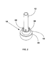
- FIG. 2 is a simplified perspective view of a sample tube and sample tube carrier used in the sample handling system of FIG. 1 ;
- FIG. 3 is a view of the sample handling system of FIG. 1 illustrating a sample handling challenge to be addressed by the present invention
- FIG. 4 is a view of the prior art automated sample handling system of FIG. 1 illustrating a sample handling buffer exemplary of the present invention
- FIG. 5 is a simplified perspective view of the sample handling buffer of FIG. 4 capturing a sample tube carrier conveyed on a track within the automated sample handling system of FIG. 1 ;
- FIG. 6 is a simplified perspective view of the sample handling buffer of the present invention transferring the sample tube carrier illustrated as being captured in FIG. 5 towards a carrier carousel portion of the present invention;
- FIG. 7 is a simplified perspective view of the sample handling buffer of the present invention transferring the sample tube carrier of FIG. 6 onto a carrier carousel portion of the present invention
- FIG. 8 is a simplified perspective view of the carrier carousel portion of the present invention transferring the sample tube carrier captured in FIG. 5 towards a sampling portion of an analyzer in FIG. 1 ;
- FIG. 9 is a simplified perspective view of the carrier carousel portion of the present invention having placed the sample tube carrier captured in FIG. 5 proximate or at the sampling portion of an analyzer of FIG. 1 ;
- FIG. 10 is a simplified perspective view of a pair of moveable carrier posts in a “capture” position advantageously employed in the present invention
- FIG. 10A is a simplified perspective view of the carrier posts of FIG. 10 in a “sampling” position advantageously employed in the present invention
- FIG. 11 is a simplified perspective view of a carrier shuttle advantageously employed in the present invention in a first position
- FIG. 12A is a simplified cut-away plan view of the carrier shuttle portion of FIG. 10 illustrating a carrier shuttle capture operating condition
- FIG. 12B is a simplified cut-away plan view of the carrier shuttle portion of FIG. 10 illustrating a carrier shuttle remove operating condition
- FIG. 13A is a simplified cut-away plan view of the carrier shuttle portion of FIG. 10 illustrating a replace carrier shuttle operating condition.
- FIG. 13B is a simplified cut-away plan view of the carrier shuttle portion of FIG. 10 illustrating a release carrier shuttle operating condition.
- FIGS. 14 A-B-C-D-E-F illustrate the sample handling buffer of the present invention presenting a “high priority” sample to an analyzer without delay from other sample tube carriers already scheduled to be processed by the same analyzer;
- FIGS. 15A and 15B illustrate the carrier shuttle portion of FIG. 10 removing and replacing a sample tube carrier onto the automated sample handling system of FIG. 1
- an automated clinical chemistry sample handling system 10 capable of automatically pre-processing and handling as necessary multiple sample containers 12 , typically test tubes 12 which may be capped or un-capped containing patient samples to be analyzed and presented to system 10 in multiple sample racks 14 .
- Each of the sample containers 12 is provided with container identification indicia, such as a bar code, indicating a patient's identification, as well as, optionally, other procedures to be accomplished upon the sample therein.
- Sample racks 14 may have additional identification indicia thereon.
- Sample handling system 10 comprises an operating base on which a first moving, for example being belt-like or of rollers or links, conveyor track 16 transports a plurality of individual sample tubes 12 carried in sample tube carriers 18 like seen in FIG. 2 in a first direction indicated by arrow 16 A from a sample tube loading/unloading station 17 to an automated centrifuge 20 to an automated tube de-capper 22 for automatically removing caps from capped sample tubes 12 and to at least one conventional clinical analyzer 24 , 26 , 28 and 30 before a second belt-like conveyor track 32 returns each sample tube 12 in a second direction 32 A opposed to direction 16 A to the sample tube loading/unloading robotic station 17 .
- a first moving for example being belt-like or of rollers or links
- conveyor track 16 transports a plurality of individual sample tubes 12 carried in sample tube carriers 18 like seen in FIG. 2 in a first direction indicated by arrow 16 A from a sample tube loading/unloading station 17 to an automated centrifuge 20 to an automated tube de-capper 22 for automatically removing caps from
- Sample tube carrier transfer and buffering stations 34 and 36 are provided for transferring sample tube carriers 18 between tracks 16 and 32 as well as for retaining sample tube carriers 18 in a temporary buffer inventory.
- Sample tube carriers 18 may be buffered in temporary inventory for a number of reasons, including possible re-testing or additional testing, to facilitate testing of high-priority samples, reducing analyzer back-log of samples awaiting analysis and the like. It will be understood that more than four analyzers 24 , 26 , 28 and 30 may be linked together and be accessible by conveyor tracks 16 and 32 .
- Sample handling system 10 has a number of sensors 38 for detecting the location of a sample tube 12 by means of identifying indicia placed on or within each sample tube carrier 18 . Conventional bar-code readers or radio-frequency locating devices may be employed in such tracking operations.
- Centrifuge 20 and each analyzer 24 , 26 , 28 and 30 are generally equipped with appropriate robotic mechanisms 40 and 42 or analyzer tracks 44 for removing a sample tube carrier 18 from conveyor track 16 or 32 , moving the sample tube carrier 18 to and from centrifuge 20 , to and from or into and out of analyzers 24 , 26 , 28 and 30 onto track 16 or 32 .
- the loading/unloading station 17 also includes X-Y-Z robotic arms 46 conventionally equipped with clamping mechanisms to remove sample tubes 12 from racks 14 and to place tubes 12 into tube carriers 18 . After all tests to be conducted on a sample in a sample tube 12 are completed, X-Y-Z robotic arms 46 remove sample tubes 12 from tube carriers 18 and replace tubes 12 in racks 14 for removal from system 10 .
- Sample handling system 10 is controlled by a conventional computer preferably a microprocessor based central processing unit CPU housed as part of or separate from the system 10 to move the sample tube carrier 18 to each operating device 20 , 24 , 26 , 28 and 30 whereat various types of processing occurs.
- the CPU controls sample handling system 10 according to software, firmware, or hardware commands or circuits like those used on the Dimension® clinical chemistry analyzer sold by Dade Behring Inc. of Deerfield, Ill., and are typical of those skilled in the art of computer-based electromechanical control programming.
- FIG. 1 illustrates two different configurations of robotic mechanisms 40 and 42 for removing and replacing a sample tube 12 from conveyor tracks 16 and 32 , in particular separate robotic mechanisms 40 and 42 are shown as moving the sample tube 12 into and then out of centrifuge 20 , respectively, while only a single robotic mechanism 44 is employed for moving the sample tube carrier 18 into and out of analyzer 28 from track 32 .
- analyzer 24 is illustrated as having a pair of analyzer tracks 41 operating in parallel to transfer sample tube carriers 18 into and out of analyzer 24 from track 16 .
- analyzer 26 is illustrated as having a pair of first and second analyzer tracks 44 F and 44 S operating in series to transfer sample tube carrier 18 into and out of analyzer 26 and from track 16 and onto track 32 , respectively.
- analyzer 30 is illustrated as having a single analyzer track 45 operable to transfer sample tube carrier 18 into and out of analyzer 30 from track 32 .
- analyzer 28 is illustrated as having a robotic device 39 operable to transfer sample tube carriers 18 into and from analyzer 28 from track 32 . All of these configurations are known in prior art systems and all lack the ability to remove a number of sample tube carriers 18 from tracks 16 or 32 and to present the sample tube carriers 18 to an analyzer in a “random” sequence, a random sequence being a sequence other than the sequential sequence at which the sample tube carriers 18 were removed from tracks 16 or 32 .
- the ability to simply and easily buffer a number of sample tube carriers 18 and to then present sample tube carriers 18 in a desired order to an analyzer is a desirable improvement in prior methods for assigning priorities for sample testing within an automated sample handling system like system 10 .
- FIG. 2 is an elevation view of an exemplary sample tube carrier 18 for transporting a sample tube container 12 , carrier 18 comprising a generally cylindrical lower carrier body 48 having a central, cylindrical hole depending from a top surface of the carrier body 48 , a raised central portion 19 and at least two vertically oriented arms 50 extending a distance upwards above body 48 , arms 50 adapted to constrain tube 12 in a generally vertical and concentric orientation.
- FIG. 3 illustrates a typical instance addressed as in the prior art by which a special sample tube 12 S is to be analyzed by clinical analyzer 26 , for example on a high-priority or emergency basis.
- a number of “routine” sample tubes 12 R in sample tube carriers 18 may be found to be buffered in first analyzer track 44 F awaiting sampling at a sampling portion or position 26 SP associated with analyzer 26 .
- one option for processing special sample tube 12 S is to control track 44 F so as to feed all of the “routine” sample tube carriers 18 R to second analyzer track 44 S and onto track 32 so that access to sampling portion 26 SP can be achieved; however, if this option is exercised, all of the released “routine” sample tube carriers 18 R must then travel back to analyzer 26 on tracks 32 and 16 before being analyzed, adversely affecting throughout.
- Another option is for special sample tube carrier 18 S to remain on track 32 or in buffer 44 F until the “routine” sample tubes 12 R have been processed in sampling portion 26 SP, and to then process special sample tube 12 S in a normal course of time, which option adversely increases the amount of time before special sample tube 12 S can be sampled and processed.
- the present invention provides a sample handling buffer 52 for enabling a single sample tube carrier 18 , for example special sample tube carrier 18 S, to be presented to a processing station, analyzer 26 in this example, from conveyor 32 in a random, independent, “out of turn” order without delays from other routine sample tube carriers 18 R already scheduled to be processed by the same analyzer 26 .
- Sample handling buffer 52 is operated so as to remove sample tube carriers 18 from either of tracks 16 or 32 and to present sample tube carriers 18 to a sampling portion or position 26 SP associated with analyzer 26 , for example, in an order that is independent from the order in which the sample tube carriers 18 were removed from tracks 16 or 32 .
- Sample handling buffer 52 thereby provides a method by which a special sample tube carrier 18 S to be analyzed by clinical analyzer 26 on a high-priority or emergency basis can by-pass a number of “routine” sample tube carriers 18 R that may have previously been removed from track 32 and are awaiting sampling at sampling position 26 SP.
- the present invention thus overcomes the above described disadvantages in performance and/or throughput experienced in prior art systems
- FIG. 5 illustrates sample handling buffer 52 as comprising an actuator 43 schematically indicated as being adapted to cause a sample carrier holder 54 (in the form of a carousel in the embodiment shown) to place a sample carrier 18 proximate sampling position 26 SP.
- the sample carrier holder carousel 54 having a number of carrier holding zones 56 formed therein.
- the carrier holding zones 56 are sized to accept a sample tube carrier 18 holding a sample tube 12 .
- an important feature of carousel 54 is the ability to align carrier holding zones 56 proximate sampling position 26 SP in a sequence other than the sequential sequence at which the sample tube carriers 18 are placed into carrier holding zones 56 .
- a carrier shuttle 58 disposed above carousel 54 and tracks 16 and 32 comprises a shuttle actuator 60 with carrier escapement device 61 on its distal end, escapement device 61 comprising a pair of carrier shuttle rods 62 and a carrier push plate 65 positioned therefrom to define a carrier capture zone 67 , sized appropriately to capture a sample carrier 18 on tracks 16 or 32 therein.
- Openings 63 are formed in track rails 64 alongside and separating tracks 16 and 32 such that carrier shuttle 58 can moveably slide a sample tube carrier 18 from either of track 16 or 32 into a carrier holding zone 56 by activating shuttle actuator 60 from a fully or partially extended condition to a closed condition as seen in the progression of operating conditions seen in FIGS. 5 , 6 and 7 .
- FIG. 5 particularly illustrates a first stage in the sample carrier removal process wherein a special sample carrier 18 S on track 16 is captured or engaged by carrier escapement device 61 at a location proximate opening 63 in rail 57 .
- a previously removed routine sample carrier 18 R is shown already supported by rotatable carrier carousel 54 .
- FIG. 6 particularly illustrates a further stage in the sample carrier removal process wherein shuttle actuator 60 has been partially retracted to moveably slide sample carrier 18 S from track 16 , through opening 63 and onto track 32 .
- FIG. 6 particularly illustrates a further stage in the sample carrier removal process wherein shuttle actuator 60 has been partially retracted to moveably slide sample carrier 18 S from track 16 , through opening 63 and onto track 32 .
- FIG. 7 particularly illustrates an even further stage in the sample carrier removal process wherein shuttle actuator 60 has been more fully retracted so as to moveably slide sample carrier 18 S from track 32 , through opening 59 and onto a carrier holding zone 56 in rotatable carrier carousel 54 .
- FIG. 8 particularly illustrates an even further stage in the sample carrier removal process wherein shuttle actuator 60 has released sample carrier 18 S into carrier holding zone 56 in rotatable carrier carousel 54 which is then rotated “counterclockwise” towards sampling position 26 SP (For purposes of simplicity, of “routine” sample tube carrier 18 R is not shown).
- FIG. 8 particularly illustrates an even further stage in the sample carrier removal process wherein shuttle actuator 60 has released sample carrier 18 S into carrier holding zone 56 in rotatable carrier carousel 54 which is then rotated “counterclockwise” towards sampling position 26 SP (For purposes of simplicity, of “routine” sample tube carrier 18 R is not shown).
- carrier escapement device 61 is operable to capture, retain and release a sample carrier 18 as necessary to enable transfer of a selected or special sample carrier 18 S from and to either track 16 or 32 and to and from any one of the number of carrier holding zones 56 within rotatable carrier carousel 54 .
- Sample carrier holder carousel 54 is positioned proximate sampling portion 26 SP of analyzer 26 as shown in FIG. 9 and advantageously is shaped as a circular plate and is rotatable using a suitable conventional source of rotary motion. Consequently, any carrier holding zone 56 on carousel 54 may be rotated into alignment with sampling portion 26 SP and in an aligned orientation, a sample tube carrier 18 S holding special sample tube 12 S may then be transferred, for example by carrier posts 69 ( FIG. 10 ) described hereinafter from the aligned carrier holding zone 56 into a sampling location in sampling portion 26 SP.
- analyzer 26 may be equipped with a moveable sampling probe capable of aspirating liquid from tube 12 S without removing tube 12 S from carrier holding zone 56 on carousel 54 so that it is not required that sample tube 12 S be transferred from the aligned carrier holding zone 56 into sampling portion 26 SP.
- a robotic-assisted moveable sampling probe is but one example of such a system.
- the sample handling buffer 52 of the present invention provides a device and method for controlling the priority at which sample tubes 12 are made available for testing by an analyzer like analyzer 26 .
- carousel 54 may be installed in conjunction with any of the sample processing devices illustrated in FIG. 3 or their equivalents without departing from the scope of the present invention. This is a key feature of the present invention that overcomes many shortcomings of prior art systems wherein samples are tested in the order removed from tracks 16 or 32 or else lower priority sample are removed from a testing location so that higher priority samples may be more quickly analyzed.
- carousel 54 may be rotated to re-align the sample tube carrier 18 with openings 59 in track rail 64 .
- Carrier shuttle 58 may be activated to extend shuttle actuator 60 thereby urging carrier push plate 65 and sample tube carrier 18 through openings 59 and 63 in order to replace sample tube carrier 18 on track 16 or 32 .
- carousel 54 is also able to control the priority at which sample tubes 12 may be replaced on track 16 or 32 for testing by a different analyzer.
- carriers 18 can be placed on track 32 to minimize time “on-board” system 10 in the event that additional tests are to be conducted by analyzers not connected to sample handling system 10 if desired.
- a pair of carrier pawls 69 spaced apart to hold a sample carrier 18 are linearly translatable within an open carrier holding zone groove 70 formed in the base of carrier holding zone 56 using a conventional source of linear motion 71 .
- the posts 69 engage opposing sides of a carrier 18 so that one post 69 can urge carrier 18 from carrier holding zone 56 and the other post 69 can urge carrier 18 from sampling position 26 SP.
- Posts 69 are thereby enabled to engage and slide a sample tube carrier 18 between carrier holding zone 56 and sampling portion 26 SP like seen in FIG. 10A in which sampling position 26 SP is removed for purposes of illustration.
- sampling portion 26 SP is illustrated as a element of analyzer 26 as is typical of many commercial analyzers.
- an analyzer like analyzer 28 may be equipped with a robotic sampling probe and be operable to aspirate sample fluid directly from a sample tube 12 in sample tube carrier 18 without removing the sample tube carrier 18 from carousel 54 so that post pawl 69 and the source of linear motion 71 are unnecessary.
- Escapement device 61 includes a pair of moveable rods 62 spaced apart and oriented appropriately to capture a single sample carrier 18 being transported on track 16 or 32 .
- the design dimensions of the sample carrier 18 will affect design dimensions of the escapement device 61 .
- FIG. 11 shows a simple but effective configuration in which a motor 68 is operable to bi-directionally rotate carrier shuttle rods 62 in a manner indicated by arrow 68 A so as to engage and release sample tube carrier 18 , for example on track 16 .
- FIG. 12A shows a simple but effective configuration in which a motor 68 is operable to bi-directionally rotate carrier shuttle rods 62 in a manner indicated by arrow 68 A so as to engage and release sample tube carrier 18 , for example on track 16 .
- FIG. 12A motor 68 has rotated carrier shuttle rods 62 slightly clockwise from an orientation parallel to track 32 so that the raised central portion 19 of sample tube carrier 18 “slips past” the leftmost carrier shuttle rod 62 but the central portion 19 contacts the rightmost carrier shuttle rod 62 and travel of sample tube carrier 18 is stopped.
- shuttle actuator 60 has been retracted so as to moveably slide sample carrier 18 from track 32 , through opening 59 and onto a carrier holding zone 56 in rotatable carrier carousel 54 .
- carousel 54 may be rotated to re-align the sample tube carrier 18 with opening 59 and shuttle actuator 60 is extended to replace sample tube carrier 18 on track 32 as seen in FIG.
- FIG. 14A is a portion of FIG. 4 and illustrates sample handling buffer 52 of the present invention as enabling a special sample tube carrier 18 S carrying a special sample tube 12 S having a “high priority” sample requiring “immediate” analysis, to be placed on track 16 by sample tube loading/unloading robotic station 17 and then presented to analyzer 26 from conveyor track 16 in an, “out of turn” order without delay from other routine sample tube carriers 18 R already scheduled to be processed by the same analyzer 26 .
- four routine sample tube carriers 18 R are “ahead” of sample tube carrier 18 S on track 32 and in prior art systems, sample tube carrier 18 S would move along track 16 , be placed on track 32 by sample tube carrier transfer and buffering station 36 and approach analyzer 26 on track 32 .
- carrier escapement device 61 is installed and is operable as seen in previous Figures, however, for purposes of clarity, escapement device 61 is seen in dotted lines and other portions of carrier shuttle 58 are not included.
- the four routine sample tube carriers 18 R “ahead” of special sample tube carrier 183 on track 32 are allowed to by pass analyzer 26 and be replaced on track 16 by buffering station 34 and will be processed after processing of special sample 123 is completed.
- the four routine sample tube carriers 18 R may be held upstream of analyzer 26 during the time special sample 123 is transferred to sampling portion 26 SP.
- special sample tube carrier 188 is removed from track 16 , transferred across track 32 , through opening 59 in rail 64 and placed in a carrier holding zone 56 on carrier carousel 54 .
- Carrier carousel 54 is then operated as explained in conjunction with FIGS. 5-8 so as to bring special sample carrier 18 S directly into alignment with sampling portion 26 SP of analyzer 26 ( FIG. 14E ) and then moved by carrier posts 69 into sampling position 26 SP ( FIG. 14F ). Meanwhile, the original four routine sample tube carriers 18 R previously “ahead” of special sample tube carrier 138 have been replaced on track 16 by buffering station 34 and may proceed to analyzer 26 for routine processing.
- FIGS. 15A and 15B illustrate special sample tube carrier 18 S (dashed lines) removed from carrier holding zone 56 and replaced on track 32 and escapement device 62 slightly rotated counter-clockwise to as to release special sample tube carrier 18 S (solid lines) onto track 32 .
- sample tube carriers 18 R can be captured by carrier escapement device 61 and placed in a carrier holding zone 56 on carrier carousel 54 using the procedure previously described in those instances when both carrier holding zones 56 on carousel 54 and transfer time are available.
- sample tube carriers 18 already in a carrier holding zone 56 can be replaced on track 16 or 32 , by reversing the capturing procedure described.
- actuator 43 is adapted to align carrier holding zones 56 proximate sampling position 26 SP in a sequence other than the sequence at which the sample tube carriers 18 are originally placed into carrier holding zones 56 , then actuator 43 can cause carousel 54 to place any of the sample tube carriers 18 proximate the processing portion of analyzer 26 in any sequence, the same sequence or a sequence different from that at which the sample tube carriers 18 were transferred into carrier holding zones 56 .
- sample tubes 12 come into the “random access” carousel 54 sequentially from the tracks 16 and 32 . Once in carousel 54 , tubes 12 can be presented to the sampling position 26 SP in any order, not bound by the order tubes 12 arrived from tracks 16 and 32 .
- sample tube 12 While a sample tube 12 is being processed at the sampling position 26 SP, carousel 54 is free to move as needed and sample tubes 12 can be moved into or out of the carousel 54 . It is also possible that sample tubes 12 could be moved out of carousel 54 in a different order than they were received and possibly in a different order than tubes 12 were processed. It is also possible that a sample tube 12 could be returned to track 16 or 32 unprocessed as the result of a change in resources that makes it not possible to process the sample tube 12 at analyzer 26 , or resources become available that make it more advantageous to process the sample at an alternate analyzer.
- FIGS. 15A and 15B illustrate special sample tube carrier 18 S (dashed lines) removed from carrier holding zone 56 and replaced on track 32 and escapement rods 62 slightly rotated counter-clockwise to as to release special sample tube carrier 18 S (solid lines) onto track 32 .
- sample handling buffer 52 could be operated as described in conjunction with FIGS. 6-8 so as to remove the four routine sample tube carriers 18 R “ahead” of special sample tube carrier 18 S from track 32 without presenting the sample tube carriers 18 R to sampling position 26 SP of analyzer 26 .
- any sample tube carriers 18 having sample tubes 12 from which samples have already been aspirated are removed from carousel 54 and/or sampling position 26 SP and replaced on track 32 .
- Sample handling buffer 52 is then operated so as to transfer the special sample tube carrier 18 S from track 32 onto carousel 54 and to operate carousel 54 in order to bring special sample tube carrier 18 S to sampling position 26 SP of analyzer 26 .
- sample handling buffer 52 is operated such that at least one carrier holding zone 56 remains empty to accommodate special sample tube 12 S.
- Sample handling buffer 52 thereby provides a method by which a special sample tube carrier 18 S to be analyzed by clinical analyzer 26 on a high-priority or emergency basis can by-pass a number of “routine” sample tube carriers 18 R waiting the queue or ahead of special sample tube carrier 18 S and be presented for sampling at sampling position 26 SP without delays experienced in prior art systems.
- the sample carrier holder has been described as being a generally circular and rotatable carousel; however, in other embodiments, the sample carrier holder would be a continuous, elongate track having a number of carrier holding zones 56 formed therein, or a conventional, flat belt, and driven in alternate directions so as to remove and replace tube carriers 18 from tracks 16 and 32 in an expeditious manner.
- a carrier holding zone 56 be formed in rotatable carrier carousel 54 as suitable alternatives, for example a ridge or pins in an upper flat surface can provide the equivalent function.
Abstract
Description
Claims (11)
Priority Applications (4)
| Application Number | Priority Date | Filing Date | Title |
|---|---|---|---|
| US11/742,897 US7681466B2 (en) | 2007-05-01 | 2007-05-01 | Programmable random access sample handler for use within and automated laboratory system |
| PCT/US2007/082546 WO2008133708A1 (en) | 2007-05-01 | 2007-10-25 | Programmable random access sample handler for use within an automated laboratory system |
| JP2010506181A JP5232853B2 (en) | 2007-05-01 | 2007-10-25 | Programmable random access sample handling device for use in automated laboratory systems |
| EP07854424.4A EP2142907B1 (en) | 2007-05-01 | 2007-10-25 | Programmable random access sample handler for use within an automated laboratory system |
Applications Claiming Priority (1)
| Application Number | Priority Date | Filing Date | Title |
|---|---|---|---|
| US11/742,897 US7681466B2 (en) | 2007-05-01 | 2007-05-01 | Programmable random access sample handler for use within and automated laboratory system |
Publications (2)
| Publication Number | Publication Date |
|---|---|
| US20080271546A1 US20080271546A1 (en) | 2008-11-06 |
| US7681466B2 true US7681466B2 (en) | 2010-03-23 |
Family
ID=39925952
Family Applications (1)
| Application Number | Title | Priority Date | Filing Date |
|---|---|---|---|
| US11/742,897 Active 2028-08-18 US7681466B2 (en) | 2007-05-01 | 2007-05-01 | Programmable random access sample handler for use within and automated laboratory system |
Country Status (4)
| Country | Link |
|---|---|
| US (1) | US7681466B2 (en) |
| EP (1) | EP2142907B1 (en) |
| JP (1) | JP5232853B2 (en) |
| WO (1) | WO2008133708A1 (en) |
Cited By (11)
| Publication number | Priority date | Publication date | Assignee | Title |
|---|---|---|---|---|
| US20080247914A1 (en) * | 2007-04-06 | 2008-10-09 | Ted Carl Edens | Sample Preparation System And Method for Processing Clinical Specimens |
| US20110073438A1 (en) * | 2009-09-25 | 2011-03-31 | Kei Takai | Sample processing apparatus, sample transporting device, and sample rack transporting method |
| WO2012141816A1 (en) * | 2011-04-13 | 2012-10-18 | Siemens Healthcare Diagnostics Inc. | Method, system, and apparatus for aligning the angle of a polar coordinate system device to the axis of an end-effector |
| WO2013070754A1 (en) | 2011-11-07 | 2013-05-16 | Beckman Coulter, Inc. | Robotic arm |
| WO2013070756A2 (en) | 2011-11-07 | 2013-05-16 | Beckman Coulter, Inc. | System and method for processing samples |
| US8703492B2 (en) | 2007-04-06 | 2014-04-22 | Qiagen Gaithersburg, Inc. | Open platform hybrid manual-automated sample processing system |
| RU2605156C2 (en) * | 2011-11-16 | 2016-12-20 | Инпеко Холдинг Лтд. | Process plant of devices for transportation of containers for biological preparation |
| EP2669684A4 (en) * | 2011-01-26 | 2018-01-10 | Hitachi High-Technologies Corporation | Specimen transportation system and method for controlling same |
| US9953141B2 (en) | 2009-11-18 | 2018-04-24 | Becton, Dickinson And Company | Laboratory central control unit method and system |
| US10288633B2 (en) | 2015-06-26 | 2019-05-14 | Abbott Laboratories | Reaction vessel moving member for moving reaction vessels from a processing track to a rotating device in a diagnostic analyzer |
| US10379130B2 (en) | 2015-06-26 | 2019-08-13 | Abbott Laboratories | Reaction vessel exchanger device for a diagnostic analyzer |
Families Citing this family (78)
| Publication number | Priority date | Publication date | Assignee | Title |
|---|---|---|---|---|
| JP5142976B2 (en) * | 2008-12-25 | 2013-02-13 | 株式会社日立ハイテクノロジーズ | Automatic analyzer |
| US20100291618A1 (en) | 2009-05-15 | 2010-11-18 | Biomerieux, Inc. | Methods for rapid identification and/or characterization of a microbial agent in a sample |
| CN102460183B (en) * | 2009-05-15 | 2015-04-15 | 生物梅里埃有限公司 | Automated loading mechanism for microbial detection apparatus |
| DE102010028769A1 (en) | 2010-05-07 | 2011-11-10 | Pvt Probenverteiltechnik Gmbh | System for transporting containers between different stations and container carriers |
| US9039992B2 (en) * | 2011-06-06 | 2015-05-26 | Abbott Laboratories | Apparatus for closed tube sampling and open tube sampling for automated clinical analyzers |
| US9335336B2 (en) | 2011-09-09 | 2016-05-10 | Gen-Probe Incorporated | Automated sample handling instrumentation, systems, processes, and methods |
| JP5923270B2 (en) * | 2011-10-07 | 2016-05-24 | 株式会社日立ハイテクノロジーズ | Sample processing system |
| EP2589966A1 (en) | 2011-11-04 | 2013-05-08 | Roche Diagnostics GmbH | Laboratory sample distribution system and corresponding method of operation |
| EP2589967A1 (en) | 2011-11-04 | 2013-05-08 | Roche Diagnostics GmbH | Laboratory sample distribution system and corresponding method of operation |
| EP2589968A1 (en) | 2011-11-04 | 2013-05-08 | Roche Diagnostics GmbH | Laboratory sample distribution system, laboratory system and method of operating |
| BR112014011035A2 (en) * | 2011-11-07 | 2017-06-13 | Beckman Coulter, Inc. | aliquot system and workflow |
| WO2013116654A1 (en) * | 2012-02-03 | 2013-08-08 | Siemens Healthcare Diagnostice, Inc. | Encoding scheme embedded into an automation track surface |
| JP6190390B2 (en) * | 2012-02-03 | 2017-08-30 | シーメンス・ヘルスケア・ダイアグノスティックス・インコーポレーテッドSiemens Healthcare Diagnostics Inc. | Intelligent intelligent multi-functional carrier and integrated automation system for material distribution and transport |
| US10101351B2 (en) | 2012-04-04 | 2018-10-16 | Siemens Healthcare Diagnostics Inc. | Method for processing priority samples that preserves a FIFO processing queue |
| WO2013177087A2 (en) | 2012-05-22 | 2013-11-28 | Siemens Healthcare Diagnostics Inc. | Linear random access queue |
| JP6037783B2 (en) * | 2012-11-06 | 2016-12-07 | 株式会社日立ハイテクノロジーズ | Automatic analysis apparatus, automatic analysis adjustment support method, and automatic analysis adjustment support program |
| JP5851659B2 (en) * | 2013-06-17 | 2016-02-03 | 株式会社日立ハイテクノロジーズ | Automatic analyzer |
| ITMI20131763A1 (en) * | 2013-10-23 | 2015-04-24 | Inpeco Holding Ltd | DEVICE FOR THE TRANSFER OF SAMPLES OF BIOLOGICAL MATERIAL BETWEEN LABORATORY AUTOMATION PLACES PLACED AT DIFFERENT HEIGHTS. |
| JP6247953B2 (en) * | 2014-02-14 | 2017-12-13 | 株式会社日立ハイテクノロジーズ | Sample processing system |
| DE102014202843B3 (en) | 2014-02-17 | 2014-11-06 | Roche Pvt Gmbh | Transport device, sample distribution system and laboratory automation system |
| DE102014202838B3 (en) | 2014-02-17 | 2014-11-06 | Roche Pvt Gmbh | Transport device, sample distribution system and laboratory automation system |
| EP2927167B1 (en) | 2014-03-31 | 2018-04-18 | F. Hoffmann-La Roche AG | Dispatch device, sample distribution system and laboratory automation system |
| EP2927625A1 (en) | 2014-03-31 | 2015-10-07 | Roche Diagniostics GmbH | Sample distribution system and laboratory automation system |
| EP2927168A1 (en) | 2014-03-31 | 2015-10-07 | Roche Diagniostics GmbH | Transport device, sample distribution system and laboratory automation system |
| EP2927163B1 (en) | 2014-03-31 | 2018-02-28 | Roche Diagnostics GmbH | Vertical conveyor, sample distribution system and laboratory automation system |
| EP2927695B1 (en) | 2014-03-31 | 2018-08-22 | Roche Diagniostics GmbH | Sample distribution system and laboratory automation system |
| EP2957914B1 (en) | 2014-06-17 | 2018-01-03 | Roche Diagnostics GmbH | Laboratory sample distribution system and laboratory automation system |
| EP2977766A1 (en) | 2014-07-24 | 2016-01-27 | Roche Diagniostics GmbH | Laboratory sample distribution system and laboratory automation system |
| EP2995580A1 (en) | 2014-09-09 | 2016-03-16 | Roche Diagniostics GmbH | Laboratory sample distribution system and laboratory automation system |
| EP2995960B1 (en) | 2014-09-09 | 2020-07-15 | Roche Diagniostics GmbH | Laboratory sample distribution system and method for calibrating magnetic sensors |
| US9952242B2 (en) | 2014-09-12 | 2018-04-24 | Roche Diagnostics Operations, Inc. | Laboratory sample distribution system and laboratory automation system |
| EP2995958A1 (en) | 2014-09-15 | 2016-03-16 | Roche Diagniostics GmbH | Method of operating a laboratory sample distribution system, laboratory sample distribution system and laboratory automation system |
| EP3006943B1 (en) | 2014-10-07 | 2020-04-22 | Roche Diagniostics GmbH | Module for a laboratory sample distribution system, laboratory sample distribution system and laboratory automation system |
| EP3016116A1 (en) | 2014-11-03 | 2016-05-04 | Roche Diagniostics GmbH | Printed circuit board arrangement, coil for a laboratory sample distribution system, laboratory sample distribution system and laboratory automation system |
| EP3070479B1 (en) | 2015-03-16 | 2019-07-03 | Roche Diagniostics GmbH | Transport carrier, laboratory cargo distribution system and laboratory automation system |
| EP3537160B1 (en) | 2015-03-23 | 2020-08-12 | Roche Diagnostics GmbH | Laboratory sample distribution system and laboratory automation system |
| EP3095739A1 (en) | 2015-05-22 | 2016-11-23 | Roche Diagniostics GmbH | Method of operating a laboratory sample distribution system, laboratory sample distribution system and laboratory automation system |
| EP3096146A1 (en) | 2015-05-22 | 2016-11-23 | Roche Diagniostics GmbH | Method of operating a laboratory sample distribution system, laboratory sample distribution system and laboratory automation system |
| EP3096145B1 (en) | 2015-05-22 | 2019-09-04 | Roche Diagniostics GmbH | Method of operating a laboratory automation system and laboratory automation system |
| EP3112874A1 (en) | 2015-07-02 | 2017-01-04 | Roche Diagnostics GmbH | Storage module, method of operating a laboratory automation system and laboratory automation system |
| EP3121603A1 (en) | 2015-07-22 | 2017-01-25 | Roche Diagnostics GmbH | Sample container carrier, laboratory sample distribution system and laboratory automation system |
| EP3139175B1 (en) | 2015-09-01 | 2021-12-15 | Roche Diagnostics GmbH | Laboratory cargo distribution system, laboratory automation system and method of operating a laboratory cargo distribution system |
| EP3153866A1 (en) | 2015-10-06 | 2017-04-12 | Roche Diagnostics GmbH | Method of determining a handover position and laboratory automation system |
| EP3153864B1 (en) * | 2015-10-06 | 2019-11-20 | Roche Diagniostics GmbH | Apparatus and method for processing at least one sample |
| EP3153867B1 (en) | 2015-10-06 | 2018-11-14 | Roche Diagniostics GmbH | Method of configuring a laboratory automation system, laboratory sample distribution system and laboratory automation system |
| EP3156352B1 (en) | 2015-10-13 | 2019-02-27 | Roche Diagniostics GmbH | Laboratory sample distribution system and laboratory automation system |
| EP3156353B1 (en) | 2015-10-14 | 2019-04-03 | Roche Diagniostics GmbH | Method of rotating a sample container carrier, laboratory sample distribution system and laboratory automation system |
| EP3196655B1 (en) * | 2016-01-22 | 2020-11-25 | Roche Diagniostics GmbH | Laboratory sample container carrier handling apparatus and laboratory system |
| EP3211428A1 (en) | 2016-02-26 | 2017-08-30 | Roche Diagnostics GmbH | Transport device unit for a laboratory sample distribution system |
| EP3211430A1 (en) | 2016-02-26 | 2017-08-30 | Roche Diagnostics GmbH | Transport device with base plate modules |
| EP3211429A1 (en) | 2016-02-26 | 2017-08-30 | Roche Diagnostics GmbH | Transport device having a tiled driving surface |
| EP3214451A1 (en) | 2016-03-03 | 2017-09-06 | Roche Diagnostics GmbH | Sample carrier handling device |
| CN109196363A (en) | 2016-06-03 | 2019-01-11 | 豪夫迈·罗氏有限公司 | Laboratory sample distribution system and laboratory automation system |
| EP3255519B1 (en) | 2016-06-09 | 2019-02-20 | Roche Diagniostics GmbH | Laboratory sample distribution system and method of operating a laboratory sample distribution system |
| EP3260867A1 (en) | 2016-06-21 | 2017-12-27 | Roche Diagnostics GmbH | Method of setting a handover position and laboratory automation system |
| EP3494398B1 (en) | 2016-08-04 | 2022-04-06 | Roche Diagnostics GmbH | Laboratory sample distribution system and laboratory automation system |
| US11360110B2 (en) | 2016-09-23 | 2022-06-14 | Hitachi High-Tech Corporation | Sample test automation system |
| EP3330717B1 (en) | 2016-12-01 | 2022-04-06 | Roche Diagnostics GmbH | Laboratory sample distribution system and laboratory automation system |
| CN106771282B (en) * | 2016-12-19 | 2018-08-10 | 宁波美康盛德生物科技有限公司 | Biochemical Analyzer guideway transit system |
| CN106771283B (en) * | 2016-12-19 | 2018-08-10 | 宁波美康盛德生物科技有限公司 | Biochemical Analyzer transport system |
| CN106771302B (en) * | 2016-12-19 | 2018-08-10 | 宁波美康盛德生物科技有限公司 | Biochemical Analyzer sample feeding propulsive mechanism |
| EP3343232B1 (en) | 2016-12-29 | 2021-09-15 | Roche Diagnostics GmbH | Laboratory sample distribution system and laboratory automation system |
| EP3355065B1 (en) | 2017-01-31 | 2021-08-18 | Roche Diagnostics GmbH | Laboratory sample distribution system and laboratory automation system |
| EP3357842B1 (en) | 2017-02-03 | 2022-03-23 | Roche Diagnostics GmbH | Laboratory automation system |
| EP3410123B1 (en) | 2017-06-02 | 2023-09-20 | Roche Diagnostics GmbH | Method of operating a laboratory sample distribution system, laboratory sample distribution system and laboratory automation system |
| EP3428653B1 (en) | 2017-07-13 | 2021-09-15 | Roche Diagnostics GmbH | Method of operating a laboratory sample distribution system, laboratory sample distribution system and laboratory automation system |
| EP3456415B1 (en) | 2017-09-13 | 2021-10-20 | Roche Diagnostics GmbH | Sample container carrier, laboratory sample distribution system and laboratory automation system |
| EP3457144B1 (en) | 2017-09-13 | 2021-10-20 | Roche Diagnostics GmbH | Sample container carrier, laboratory sample distribution system and laboratory automation system |
| LU100524B1 (en) * | 2017-11-29 | 2019-06-12 | Stratec Biomedical Ag | Sample and supplies track |
| EP3540443B1 (en) | 2018-03-16 | 2023-08-30 | Roche Diagnostics GmbH | Laboratory system, laboratory sample distribution system and laboratory automation system |
| EP3561517B1 (en) | 2018-04-25 | 2021-04-21 | Aoi Seiki Co., Ltd. | Holder transport apparatus |
| CN108652682B (en) * | 2018-05-18 | 2019-12-10 | 徐站站 | automatic urine sample collecting equipment for hospital |
| CN108670311B (en) * | 2018-05-18 | 2019-09-06 | 邵明秀 | A kind of clinical laboratory's urine specimen automation collection equipment |
| CN108670312B (en) * | 2018-05-18 | 2019-09-13 | 徐静 | A kind of clinical laboratory's urine specimen acquisition equipment |
| JP7124073B2 (en) * | 2018-06-04 | 2022-08-23 | 株式会社日立ハイテク | Connection device and laboratory test automation system equipped with the same |
| JP7274598B2 (en) * | 2019-10-31 | 2023-05-16 | 株式会社日立ハイテク | Connection device and laboratory test automation system |
| US11747356B2 (en) | 2020-12-21 | 2023-09-05 | Roche Diagnostics Operations, Inc. | Support element for a modular transport plane, modular transport plane, and laboratory distribution system |
| CN112985912B (en) * | 2021-03-19 | 2022-06-28 | 合肥工业大学 | Sampling device for food detection |
Citations (10)
| Publication number | Priority date | Publication date | Assignee | Title |
|---|---|---|---|---|
| US4861553A (en) | 1987-06-11 | 1989-08-29 | Technicon Instruments Corporation | Automatic sampling system |
| US5008082A (en) | 1988-08-25 | 1991-04-16 | Eastman Kodak Company | Analyzers using linear sample trays with random access |
| US5350564A (en) * | 1993-06-28 | 1994-09-27 | Baxter Diagnostics Inc. | Automated chemical analyzer with apparatus and method for conveying and temporary storage of sample tubes |
| US5972295A (en) | 1997-01-29 | 1999-10-26 | Hitachi, Ltd. | Automatic analyzing apparatus |
| US6290907B1 (en) | 1997-09-11 | 2001-09-18 | Hitachi, Ltd. | Sample handling system |
| US6358472B1 (en) | 1998-07-10 | 2002-03-19 | Bayer Corporation | Stat shuttle transport device |
| US6843357B2 (en) * | 2002-07-26 | 2005-01-18 | Cardinal Health 301, Inc. | Two-axis robot for specimen transfer |
| US6890485B1 (en) | 1997-05-16 | 2005-05-10 | Aurora Discovery, Inc. | High throughput chemical handling system |
| US7011792B2 (en) | 1996-03-11 | 2006-03-14 | Hitachi, Ltd. | Analyzer system having sample rack transfer line |
| US20060148063A1 (en) | 2003-05-14 | 2006-07-06 | Fauzzi John A | Method and apparatus for automated pre-treatment and processing of biological samples |
Family Cites Families (7)
| Publication number | Priority date | Publication date | Assignee | Title |
|---|---|---|---|---|
| JPS61209343A (en) * | 1985-03-13 | 1986-09-17 | Konishiroku Photo Ind Co Ltd | Biochemical analyser |
| JP3226233B2 (en) * | 1993-01-07 | 2001-11-05 | 株式会社東芝 | Automatic analyzer |
| JPH07239333A (en) * | 1994-02-28 | 1995-09-12 | Matsushita Electric Ind Co Ltd | Specimen inspection system |
| JP3771840B2 (en) * | 2001-12-27 | 2006-04-26 | アロカ株式会社 | Microplate transfer device |
| FR2867861B1 (en) * | 2004-03-16 | 2006-07-14 | Abx Sa | DEVICE FOR SUPPLYING TOTAL BLOOD ANALYZERS |
| EP1800139A1 (en) * | 2004-09-30 | 2007-06-27 | Lifescan Scotland Limited | Cassette assembly drive means and method |
| US7670553B2 (en) * | 2005-03-24 | 2010-03-02 | Siemens Healthcare Diagnostics Inc. | Carousel system for automated chemical or biological analyzers employing linear racks |
-
2007
- 2007-05-01 US US11/742,897 patent/US7681466B2/en active Active
- 2007-10-25 WO PCT/US2007/082546 patent/WO2008133708A1/en active Application Filing
- 2007-10-25 EP EP07854424.4A patent/EP2142907B1/en active Active
- 2007-10-25 JP JP2010506181A patent/JP5232853B2/en active Active
Patent Citations (10)
| Publication number | Priority date | Publication date | Assignee | Title |
|---|---|---|---|---|
| US4861553A (en) | 1987-06-11 | 1989-08-29 | Technicon Instruments Corporation | Automatic sampling system |
| US5008082A (en) | 1988-08-25 | 1991-04-16 | Eastman Kodak Company | Analyzers using linear sample trays with random access |
| US5350564A (en) * | 1993-06-28 | 1994-09-27 | Baxter Diagnostics Inc. | Automated chemical analyzer with apparatus and method for conveying and temporary storage of sample tubes |
| US7011792B2 (en) | 1996-03-11 | 2006-03-14 | Hitachi, Ltd. | Analyzer system having sample rack transfer line |
| US5972295A (en) | 1997-01-29 | 1999-10-26 | Hitachi, Ltd. | Automatic analyzing apparatus |
| US6890485B1 (en) | 1997-05-16 | 2005-05-10 | Aurora Discovery, Inc. | High throughput chemical handling system |
| US6290907B1 (en) | 1997-09-11 | 2001-09-18 | Hitachi, Ltd. | Sample handling system |
| US6358472B1 (en) | 1998-07-10 | 2002-03-19 | Bayer Corporation | Stat shuttle transport device |
| US6843357B2 (en) * | 2002-07-26 | 2005-01-18 | Cardinal Health 301, Inc. | Two-axis robot for specimen transfer |
| US20060148063A1 (en) | 2003-05-14 | 2006-07-06 | Fauzzi John A | Method and apparatus for automated pre-treatment and processing of biological samples |
Cited By (18)
| Publication number | Priority date | Publication date | Assignee | Title |
|---|---|---|---|---|
| US7985375B2 (en) | 2007-04-06 | 2011-07-26 | Qiagen Gaithersburg, Inc. | Sample preparation system and method for processing clinical specimens |
| US20080247914A1 (en) * | 2007-04-06 | 2008-10-09 | Ted Carl Edens | Sample Preparation System And Method for Processing Clinical Specimens |
| US9476895B2 (en) | 2007-04-06 | 2016-10-25 | Becton, Dickinson And Company | Open platform automated sample processing system |
| US8703492B2 (en) | 2007-04-06 | 2014-04-22 | Qiagen Gaithersburg, Inc. | Open platform hybrid manual-automated sample processing system |
| US8839944B2 (en) * | 2009-09-25 | 2014-09-23 | Sysmex Corporation | Sample processing apparatus, sample transporting device, and sample rack transporting method |
| US20110073438A1 (en) * | 2009-09-25 | 2011-03-31 | Kei Takai | Sample processing apparatus, sample transporting device, and sample rack transporting method |
| US11355220B2 (en) | 2009-11-18 | 2022-06-07 | Becton, Dickinson And Company | Laboratory central control unit method and system |
| US9953141B2 (en) | 2009-11-18 | 2018-04-24 | Becton, Dickinson And Company | Laboratory central control unit method and system |
| EP2669684A4 (en) * | 2011-01-26 | 2018-01-10 | Hitachi High-Technologies Corporation | Specimen transportation system and method for controlling same |
| US9233377B2 (en) * | 2011-04-13 | 2016-01-12 | Siemens Healthcare Diagnostics Inc. | Method, system, and apparatus for aligning the angle of a polar coordinate system device to the axis of an end-effector |
| US20140045673A1 (en) * | 2011-04-13 | 2014-02-13 | Siemens Healthcare Diagnostics Inc. | Method, system, and apparatus for aligning the angle of a polar coordinate system device to the axis of an end-effector |
| WO2012141816A1 (en) * | 2011-04-13 | 2012-10-18 | Siemens Healthcare Diagnostics Inc. | Method, system, and apparatus for aligning the angle of a polar coordinate system device to the axis of an end-effector |
| WO2013070756A2 (en) | 2011-11-07 | 2013-05-16 | Beckman Coulter, Inc. | System and method for processing samples |
| WO2013070754A1 (en) | 2011-11-07 | 2013-05-16 | Beckman Coulter, Inc. | Robotic arm |
| RU2605156C2 (en) * | 2011-11-16 | 2016-12-20 | Инпеко Холдинг Лтд. | Process plant of devices for transportation of containers for biological preparation |
| US10288633B2 (en) | 2015-06-26 | 2019-05-14 | Abbott Laboratories | Reaction vessel moving member for moving reaction vessels from a processing track to a rotating device in a diagnostic analyzer |
| US10379130B2 (en) | 2015-06-26 | 2019-08-13 | Abbott Laboratories | Reaction vessel exchanger device for a diagnostic analyzer |
| US11733257B2 (en) | 2015-06-26 | 2023-08-22 | Abbott Laboratories | Reaction vessel moving member for moving reaction vessels from a processing track to a rotating device in a diagnostic analzyer |
Also Published As
| Publication number | Publication date |
|---|---|
| EP2142907A4 (en) | 2017-10-18 |
| JP5232853B2 (en) | 2013-07-10 |
| US20080271546A1 (en) | 2008-11-06 |
| EP2142907A1 (en) | 2010-01-13 |
| EP2142907B1 (en) | 2019-04-17 |
| JP2010526289A (en) | 2010-07-29 |
| WO2008133708A1 (en) | 2008-11-06 |
Similar Documents
| Publication | Publication Date | Title |
|---|---|---|
| US7681466B2 (en) | Programmable random access sample handler for use within and automated laboratory system | |
| EP1649294B1 (en) | Assay testing diagnostic analyzer | |
| US6588625B2 (en) | Sample handling system | |
| CN107966576B (en) | Automated diagnostic analyzer with rear accessible track system and related methods | |
| US8232103B2 (en) | Merge stop gate for an automated laboratory sample handling worksystem | |
| EP2455763B1 (en) | Junction, device and process for transporting sample racks | |
| EP2804002A1 (en) | Laboratory automated system with common sample buffer module | |
| EP2765426A1 (en) | Specimen processing system | |
| JPH0634642A (en) | Vessel transfer equipment | |
| US20230176084A1 (en) | Gripper apparatus with reduced contamination risk |
Legal Events
| Date | Code | Title | Description |
|---|---|---|---|
| AS | Assignment |
Owner name: DADE BEHRING INC., ILLINOIS Free format text: ASSIGNMENT OF ASSIGNORS INTEREST;ASSIGNORS:MILLER, KERRY LYNN;GEBRIAN, PETER LOUIS;REEL/FRAME:019362/0872 Effective date: 20070320 Owner name: DADE BEHRING INC.,ILLINOIS Free format text: ASSIGNMENT OF ASSIGNORS INTEREST;ASSIGNORS:MILLER, KERRY LYNN;GEBRIAN, PETER LOUIS;REEL/FRAME:019362/0872 Effective date: 20070320 |
|
| AS | Assignment |
Owner name: SIEMENS HEALTHCARE DIAGNOSTICS INC., ILLINOIS Free format text: MERGER;ASSIGNOR:DADE BEHRING INC.;REEL/FRAME:022625/0376 Effective date: 20071231 Owner name: SIEMENS HEALTHCARE DIAGNOSTICS INC.,ILLINOIS Free format text: MERGER;ASSIGNOR:DADE BEHRING INC.;REEL/FRAME:022625/0376 Effective date: 20071231 |
|
| XAS | Not any more in us assignment database |
Free format text: MERGER;ASSIGNOR:DADE BEHRING INC.;REEL/FRAME:022488/0395 |
|
| STCF | Information on status: patent grant |
Free format text: PATENTED CASE |
|
| CC | Certificate of correction | ||
| CC | Certificate of correction | ||
| FPAY | Fee payment |
Year of fee payment: 4 |
|
| FPAY | Fee payment |
Year of fee payment: 8 |
|
| MAFP | Maintenance fee payment |
Free format text: PAYMENT OF MAINTENANCE FEE, 12TH YEAR, LARGE ENTITY (ORIGINAL EVENT CODE: M1553); ENTITY STATUS OF PATENT OWNER: LARGE ENTITY Year of fee payment: 12 |