US7679883B2 - Ultracapacitors comprised of mineral microtubules - Google Patents
Ultracapacitors comprised of mineral microtubules Download PDFInfo
- Publication number
- US7679883B2 US7679883B2 US12/145,489 US14548908A US7679883B2 US 7679883 B2 US7679883 B2 US 7679883B2 US 14548908 A US14548908 A US 14548908A US 7679883 B2 US7679883 B2 US 7679883B2
- Authority
- US
- United States
- Prior art keywords
- electrode
- microtubules
- halloysite
- ultracapacitor
- clay
- Prior art date
- Legal status (The legal status is an assumption and is not a legal conclusion. Google has not performed a legal analysis and makes no representation as to the accuracy of the status listed.)
- Active
Links
Images


Classifications
-
- B—PERFORMING OPERATIONS; TRANSPORTING
- B01—PHYSICAL OR CHEMICAL PROCESSES OR APPARATUS IN GENERAL
- B01D—SEPARATION
- B01D61/00—Processes of separation using semi-permeable membranes, e.g. dialysis, osmosis or ultrafiltration; Apparatus, accessories or auxiliary operations specially adapted therefor
- B01D61/14—Ultrafiltration; Microfiltration
- B01D61/20—Accessories; Auxiliary operations
-
- B—PERFORMING OPERATIONS; TRANSPORTING
- B01—PHYSICAL OR CHEMICAL PROCESSES OR APPARATUS IN GENERAL
- B01D—SEPARATION
- B01D63/00—Apparatus in general for separation processes using semi-permeable membranes
- B01D63/06—Tubular membrane modules
-
- B—PERFORMING OPERATIONS; TRANSPORTING
- B01—PHYSICAL OR CHEMICAL PROCESSES OR APPARATUS IN GENERAL
- B01D—SEPARATION
- B01D63/00—Apparatus in general for separation processes using semi-permeable membranes
- B01D63/06—Tubular membrane modules
- B01D63/069—Tubular membrane modules comprising a bundle of tubular membranes
-
- B—PERFORMING OPERATIONS; TRANSPORTING
- B01—PHYSICAL OR CHEMICAL PROCESSES OR APPARATUS IN GENERAL
- B01D—SEPARATION
- B01D63/00—Apparatus in general for separation processes using semi-permeable membranes
- B01D63/08—Flat membrane modules
-
- H—ELECTRICITY
- H01—ELECTRIC ELEMENTS
- H01G—CAPACITORS; CAPACITORS, RECTIFIERS, DETECTORS, SWITCHING DEVICES OR LIGHT-SENSITIVE DEVICES, OF THE ELECTROLYTIC TYPE
- H01G11/00—Hybrid capacitors, i.e. capacitors having different positive and negative electrodes; Electric double-layer [EDL] capacitors; Processes for the manufacture thereof or of parts thereof
- H01G11/22—Electrodes
- H01G11/24—Electrodes characterised by structural features of the materials making up or comprised in the electrodes, e.g. form, surface area or porosity; characterised by the structural features of powders or particles used therefor
-
- H—ELECTRICITY
- H01—ELECTRIC ELEMENTS
- H01G—CAPACITORS; CAPACITORS, RECTIFIERS, DETECTORS, SWITCHING DEVICES OR LIGHT-SENSITIVE DEVICES, OF THE ELECTROLYTIC TYPE
- H01G11/00—Hybrid capacitors, i.e. capacitors having different positive and negative electrodes; Electric double-layer [EDL] capacitors; Processes for the manufacture thereof or of parts thereof
- H01G11/22—Electrodes
- H01G11/30—Electrodes characterised by their material
-
- H—ELECTRICITY
- H01—ELECTRIC ELEMENTS
- H01G—CAPACITORS; CAPACITORS, RECTIFIERS, DETECTORS, SWITCHING DEVICES OR LIGHT-SENSITIVE DEVICES, OF THE ELECTROLYTIC TYPE
- H01G11/00—Hybrid capacitors, i.e. capacitors having different positive and negative electrodes; Electric double-layer [EDL] capacitors; Processes for the manufacture thereof or of parts thereof
- H01G11/52—Separators
-
- H—ELECTRICITY
- H01—ELECTRIC ELEMENTS
- H01G—CAPACITORS; CAPACITORS, RECTIFIERS, DETECTORS, SWITCHING DEVICES OR LIGHT-SENSITIVE DEVICES, OF THE ELECTROLYTIC TYPE
- H01G11/00—Hybrid capacitors, i.e. capacitors having different positive and negative electrodes; Electric double-layer [EDL] capacitors; Processes for the manufacture thereof or of parts thereof
- H01G11/54—Electrolytes
-
- Y—GENERAL TAGGING OF NEW TECHNOLOGICAL DEVELOPMENTS; GENERAL TAGGING OF CROSS-SECTIONAL TECHNOLOGIES SPANNING OVER SEVERAL SECTIONS OF THE IPC; TECHNICAL SUBJECTS COVERED BY FORMER USPC CROSS-REFERENCE ART COLLECTIONS [XRACs] AND DIGESTS
- Y02—TECHNOLOGIES OR APPLICATIONS FOR MITIGATION OR ADAPTATION AGAINST CLIMATE CHANGE
- Y02E—REDUCTION OF GREENHOUSE GAS [GHG] EMISSIONS, RELATED TO ENERGY GENERATION, TRANSMISSION OR DISTRIBUTION
- Y02E60/00—Enabling technologies; Technologies with a potential or indirect contribution to GHG emissions mitigation
- Y02E60/13—Energy storage using capacitors
Definitions
- compositions and articles that include microtubules of halloysite clay; and more particularly to compositions comprised of halloysite clay microtubules that have high electrical capacitance, and articles comprised of halloysite clay microtubules which may be used as ultracapacitors in electrical circuits.
- compositions of matter that have high electrical capacitance and articles comprised of such compositions which may be used as ultracapacitors in electrical circuits.
- such materials including microscopic tubular particles, also known in the art as tubules, microtubules, nanotubules, microtubes, and nanotubes.
- tubules also known in the art as tubules, microtubules, nanotubules, microtubes, and nanotubes.
- such particles may also be referred to as rods or needles.
- tubular particles is the carbon nanotube, which, in various forms, may have a diameter of between about one nanometer and several hundred nanometers, and a length of up to several thousand nanometers long.
- microtubular materials do not occur in nature, or at least not in substantial quantities that make such microtubular materials useful in formulating compositions of matter and/or products in high volume at low cost.
- Such microtubular materials typically must be synthesized, usually in gram-sized or smaller quantities, resulting in unit manufacturing costs for compositions or products including such microtubular materials that are exceedingly high.
- inorganic microtubular material that does occur in nature in large quantities in mineral form.
- Such material belong to the kaolinite group of clay minerals, and is described in U.S. Pat. No. 5,651,976, “Controlled release of active agents using inorganic tubules,” of Price et al., the disclosure of which is incorporated herein by reference.
- Price et al. describe the kaolinite group of minerals as follows:
- both hydrated and dehydrated halloysite comprise layers of single silica tetrahedral and alumina octahedral units. They differ in the presence or absence of a layer of water molecules between the silicate and alumina layers.
- the basal spacing of the dehydrated form is about 7.2 ⁇ and the basal spacing of the hydrated form is about 10.1 ⁇ . (hence the names halloysite 7 ⁇ and halloysite 10 ⁇ ).
- the difference, about 2.9 ⁇ , is about the thickness of a monolayer of water molecules.
- “Halloysite 10 ⁇ dehydrates to halloysite 7 ⁇ at about 110° C. All structural water is lost at about 575° C.
- the interlayer water in halloysite 10 ⁇ may be replaced by organic liquids such as ethylene glycol, di- and triethylene glycol, and glycerine.
- Cylindrite belongs to the class of minerals known as sulfosalts.
- Boulangerite another mineral that will, under appropriate conditions, form tubules and other microstructures is boulangerite. Boulangerite also belongs to the class of minerals known as sulfosalts.”
- a material selected from the group consisting of hydrated halloysite and montmorillonite As is disclosed in column 1 of such patent, “The purified and swollen inorganic gel prepared from a clay such as montmorillonite group, vermiculite, hydrated halloysite, etc., by the manner described hereinafter contains free water, bound water, and water of crystallization . . . ”
- a composition for use in the delivery of an active agent at an effective rate for a selected time comprising: hollow mineral microtubules selected from the group consisting of halloysite, cylindrite, boulangerite, and imogolite, wherein said microtubules have inner diameters ranging from about 200 ⁇ to about 2000 ⁇ , and have lengths ranging from about 0.1 ⁇ m to about 2.0 ⁇ m, wherein said active agent is selected from the group consisting of pesticides, antibiotics, antihelmetics, antifouling compounds, dyes, enzymes, peptides. bacterial spores, fungi, hormones, and drugs and is contained within the lumen of said microtubules, and wherein outer and end surfaces of said microtubules are essentially free of said adsorbed active agent.”
- a composition for use in the delivery of an active agent, at an effective rate for a selected time, into a fluid use environment wherein said active agent has a limited solubility comprising: hollow cylindrical mineral microtubules selected from the group consisting of halloysite, cylindrite, boulangerite, and imogolite, wherein said microtubules have inner diameters ranging from about 200 ⁇ to about 2000 ⁇ , and have lengths ranging from about 0.1 ⁇ m to about 2.0 ⁇ m, wherein said active agent is selected from the group consisting of pesticides, antibiotics, antihelmetics, antifouling compounds, dyes, enzymes, peptides, bacterial spores, fungi, hormones, and drugs and is adsorbed onto an inner surface of said microtubules, wherein said microtubules are adherently coated with a coating, wherein said
- the preselected release profile may be achieved by controlling the length or length distribution of the tubules, or by placing degradable endcaps over some or all of the tubules in the population, or by combinations of these methods.
- Price et al. further disclose a preferred population of tubules having a preselected release profile to provide a preselected release rate curve for controlled delivery of the active agent.
- release rates are expressed in terms of Fick's second law for unsteady state diffusion, and in terms of certain tubule length distributions.
- Price et al. disclose a method for delivering encapsulated materials to a subsurface environment, for the treatment of such subsurface environment, having the steps of: (a) loading the lumen of hollow microtubules with an active agent selected for treating the subsurface environment, where the hollow microtubules are compatible with the subsurface environment; and (b) administering the hollow microtubules to the subsurface environment, permitting the controlled release of the active agent into the subsurface environment.
- the method may be practiced using a slurry of hollow microtubules, where the lumen of these microtubules is loaded with an agent for the treatment of petroleum well environments, and where these loaded microtubules are dispersed in a liquid phase carrier selected from aqueous carriers, non-aqueous carriers, and emulsions of aqueous and non-aqueous materials.
- a liquid phase carrier selected from aqueous carriers, non-aqueous carriers, and emulsions of aqueous and non-aqueous materials.
- the method may also be practiced using a pill made of a consolidated mass of tubules loaded with one or more active agents, typically bound with a binder. This method of Price et al is particularly related to treating subsurface liquid reservoirs, particularly oil reservoirs.
- the method relates to treating oil reservoirs to prevent and/or remedy such problems as fouling of extraction wells by scale formation, well corrosion, and souring of oil by bacterial contamination, and to treating the liquid in such reservoirs by introducing chemical or biological agents, to affect the properties of the liquid or to aid in the extraction of the liquid.
- Santilli discloses, “codispersed rods of a first fibrous clay and a second fibrous clay, the first fibrous clay composed predominantly of fibers with a length range of 0.5-2 microns and a diameter range of 0.04-0.2 microns and a second fibrous clay predominantly composed of rods having a length range of 1-5 microns and a diameter range of 50-100 Angstroms.
- a preferred first clay is the tubular form of the clay halloysite and a preferred second clay is fibrous attapulgite. It is preferred that the composition be at least 5 percent attapulgite. It is preferred that the composition contain up to 15 percent of a binding refractory inorganic oxide.
- the refractory inorganic oxide be alumina. It is preferred that the catalyst body have a total pore volume of at least 0.35 cc/g and at least 60 percent of the volume of the pores is present in pores having diameters of 200-700 Angstroms. It is preferred that the composition also include at least one metal selected from the transition metals.
- This invention also comprises a method for hydroprocessing hydrocarbonaceous feedstocks comprising contacting the feedstocks with molecular hydrogen under hydroprocessing conditions in the presence of a catalyst having codispersed rods of a first fibrous clay having rods predominantly in the range of 0.5-2 microns with a diameter range of 0.04-0.2 microns and a second fibrous clay having rods in the range of 1-microns and a diameter range of 50-100 Angstroms. It is preferred that the first fibrous clay be halloysite and the second clay be attapulgite.”
- halloysite can make a suitable catalyst for use in demetalizing and hydroprocessing asphaltenes.
- the halloysite is processed to break up the bundles of rods so that each rod is freely movable with respect to the other rod.
- the rods are defined herein as ‘dispersed’.
- the dispersed rod clay is dried and calcined, the random orientation of the rods provides pores of an appropriate size for hydroprocessing and hydrodemetalizing asphaltene fractions.
- the dispersion can be shaped, dried and calcined to provide a porous body having a large pore volume present as 200-700 Angstroms diameter pores.
- the shaping is by extrusion, however, it has been found that mixtures of dispersed clay rods of the halloysite type, do not extrude well.
- the rods on the surface of the extruded bodies tend to realign, destroying the desirable pore structure at the surface of the catalyst. This is defined herein as a ‘skin effect’.
- Codispersed is defined herein as having rod- or tube-like clay particles of at least two distinct types substantially randomly oriented to one another.”
- Halloysite is mined and sold commercially from mines in New Zealand and in Juab County, Utah. Reference may be had to http://www.atlasmining.com/dragonmine.html, the web site of the Atlas Mining Company of Osborn, Id. which describes and shows certain operations of the Dragon Mine in the Tintic Mining District in Joab County, Utah.
- the halloysite clay obtained from the Dragon Mine is among the highest in purity and in proportion of microtubules, such halloysite clay is not obtained in a state that is suitable for direct use as a vehicle for loading and controlled release of active agents, or for use in other high precision applications such as e.g., ultracapacitors for use in electrical and electronics circuits and devices.
- U.S. Pat. No. 3,648,126 “Electrical Capacitor Employing Paste Electrodes,” discloses an electrolytic capacitor that uses a pair of paste electrodes made from active carbon and powdered metal to maximize the electrode/electrolyte surface area by providing a highly porous carbon electrode which forms extensive boundary surfaces on exposure to an electrolyte, thus forming a high surface area electrical double layer.
- an ultracapacitor comprising a first electrode containing mineral microtubules, a second electrode containing mineral microtubules, an electrolyte disposed between said first electrode and said second electrode, and a separator disposed in said electrolyte to provide electrical insulation between said first electrode and said second electrode, while allowing ion flow within said electrolyte.
- the electrodes may be formed from a paste containing mineral microtubules, or may consist essentially of a conductive polymer containing mineral microtubules, or an aerogel containing the mineral microtubules.
- the mineral microtubules may be filled with carbon, a psuedocapacitance material, or a magnetoresistive material.
- the mineral microtubules may also be coated with a photoconductive material.
- the mineral microtubules are halloysite microtubules.
- an ultracapacitor comprising a first base electrode; a first electrode coating deposited on said first base electrode wherein said first electrode coating contains mineral microtubules; a second base electrode; a second electrode coating deposited on said second base electrode wherein said second electrode coating contains mineral microtubules; an electrolyte disposed between said first electrode coating and said second electrode coating; and a separator disposed in said electrolyte to provide electrical insulation between said first electrode coating and said second electrode coating, while allowing ion flow within said electrolyte.
- FIG. 1 is a flow diagram of a general process for converting a mined microtubule clay mineral into a product, or for preparing such mineral for use in a process;
- FIG. 2 is a schematic diagram of one preferred process for performing the step of final comminution of halloysite clay particles without substantial crushing or length reduction of the microtubules thereof;
- FIG. 3 is a side cross-sectional view of one preferred cross flow filter for use in the process of FIG. 2 ;
- FIG. 4 is a perspective view of halloysite nanotubules suspended in a fluidized state proximate to a substrate comprising microchannels;
- FIG. 5A is a perspective view of halloysite nanotubules deposited in the microchannels of the substrate of FIG. 4 ;
- FIG. 5B is a side elevation view of a halloysite nanotubule deposited in a microchannel of the substrate of FIG. 5A , taken along the line 5 B- 5 B of FIG. 5A ;
- FIG. 5C is a side elevation view of a plurality of halloysite nanotubules deposited in a microchannel of the substrate of FIG. 4 ;
- FIG. 6 is a top view of a microfluidic substrate comprising an array of microchannels containing nanotubules
- FIG. 7 is a side cross-sectional view of a distributed charge storage device structure comprising halloysite tubules
- FIG. 8 shows the distributed charge storage device structure of FIG. 7 containing a substrate and a layer of conductive polymer with halloysite microtubules in the presence of a magnetic field at the moment that such magnetic field is applied;
- FIG. 9 shows the distributed charge storage device structure of FIG. 7 containing a substrate and a layer of conductive polymer with halloysite microtubules in the presence of a magnetic field at steady state conditions
- FIG. 10A-FIG . 10 I are schematic illustrations of a sequence of steps in one process of fabricating a direct written or printed microchannel that is bounded by at least one wall comprised of nanotubules;
- FIG. 11 is a plan view of a microchannel formed on a substrate by the process of FIG. 10A-10I ;
- FIG. 12 is a flow diagram of an alternate general process for converting a mined microtubule clay mineral into a product, or for preparing such mineral for use in a process;
- FIG. 13 is a cross sectional view of an ultracapacitor having electrodes containing mineral microtubules
- FIG. 14 is a cross sectional view of an ultracapacitor having composite electrodes with a mineral microtubule based coating
- FIG. 15 is a cross sectional view of an ultracapacitor having a hybrid electrode configuration wherein one electrode is a composite electrode with a mineral microtubule coating;
- FIG. 16 is a cross sectional view of an ultracapacitor having a hybrid electrode configuration wherein one electrode contains mineral microtubules;
- FIG. 17 is a cross sectional view of an ultracapacitor having a hybrid electrode configuration wherein one electrode contains mineral microtubules and one electrode is a composite electrode with a mineral microtubule coating;
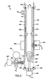
- FIG. 18 depicts a wound ultracapacitor that has been partially unwound to show the layers comprising such ultracapacitor.
- FIG. 19 is a cross sectional image of halloysite microtubules.
- a two phase fluid is meant to be a fluid comprising a liquid phase in which either substantially solid particles are dispersed therethrough, or a first liquid phase in which droplets or particles of a second liquid phase immiscible with such first liquid phase are dispersed through such first liquid phase.
- a multiphase fluid is meant to be a fluid comprising a first liquid phase in which at least one additional second solid or liquid phase is dispersed therethrough.
- a particle is meant to be a discreet liquid droplet or a solid object, with a characteristic dimension such as a diameter or length of between about one nanometer, and about several centimeters.
- a characteristic dimension such as a diameter or length of between about one nanometer, and about several centimeters.
- the particular size of particles in a fluid being processed will depend upon the particular application.
- a dispersion is meant to be any fluid comprising a liquid phase in which substantially solid particles are suspended, and remain suspended, at least temporarily.
- a slurry is meant to be any fluid comprising a liquid phase in which substantially solid particles are present. Such particles may or may not be suspended in such fluid.
- microtubule and nanotubule are used interchangeably, and are to be taken to mean a microscopic cylindrical tubular shaped material entity having a diameter between about 10 and about 500 nanometers, and a length of between about 100 and about 5000 nanometers.
- composite electrode is meant to be an ultracapacitor electrode that is made from more than one material.
- hybrid electrode is taken to be a capacitive structure that contains electrodes of different material compositions.
- FIG. 1 is a flow diagram of a general process for converting a mined microtubule clay mineral into a product, or for preparing such mineral for use in a process.
- process 1 begins with the step 10 of mining of halloysite raw clay.
- the raw halloysite clay comprises halloysite platelets and halloysite tubules (to be described subsequently in this specification), and various undesired other heterogeneous material, i.e. rocks and dirt comprised of other minerals.
- the raw mined clay may undergo an initial comminution step 100 wherein such large structures or lumps are crushed down into smaller, more uniformly sized pieces that can be further processed.
- the initial comminution step may be performed by e.g., a jaw crusher or a gyratory crusher in circumstances where the mined raw clay contains hard rock material.
- the structure and operation of such crushers are described in detail in the aforementioned SME Mining Engineering Handbook , Chapter 25, sections 25.3.1.2-25.3.1.5.
- initial comminution step 100 the maximum size of lumps in the mined raw clay is reduced down to no greater than about one inch.
- Initial comminution 100 when utilized, is followed by secondary and/or tertiary comminution/crushing 200 .
- the objective of secondary/tertiary crushing is to break the mined clay and entrained foreign material (rocks/lumps comprising other minerals) down to a size that is granular, wherein the foreign material has fractured from and is thus separable from the halloysite clay. It is also preferable that the secondary/tertiary crushing breaks the mined clay down to a granule size that is several orders of magnitude greater that the length dimension of a halloysite microtubule, i.e. on the order of about 0.1 inch or about 2 millimeters.
- Suitable apparatus for secondary and/or tertiary crushing 200 include cone crushers such as the Nordberg® Symons, Omnicone, Gyrodisc, or WaterflushTM Wet Cone crusher, all of which are manufactured and sold by Metso Minerals Industries Inc. of Danville Pa.
- cone crushers such as the Nordberg® Symons, Omnicone, Gyrodisc, or WaterflushTM Wet Cone crusher, all of which are manufactured and sold by Metso Minerals Industries Inc. of Danville Pa.
- WaterflushTM Wet Cone crusher it is noted at Chapter 25, page 2190, of the aforementioned SME Mining Engineering Handbook , “Wet Cone crushers (WF Series) use WaterflushTM technology in which water is added to the crusher to flush fines through the crushing cavity.
- flushing produces a significant amount of flaky, shaped particles that break easily during ball milling.” This capability is advantageous, since it is preferred that minimal attrition be performed at the nanoscale level which would result in the crushing or length reduction of the halloysite tubules.
- the aforementioned cone crushers are generally intended for processing of large volumes of clay mineral, on the order of many tons.
- there are alternate “lab scale” crushers that are sized for the processing of volumes from about ten pounds to about one ton of clay feedstock.
- secondary/tertiary crushing 200 is the optional step of initial purification 300 .
- a separation is made wherein particles consisting essentially of halloysite clay are separated from particles consisting of other minerals and/or other foreign material.
- the crushed material from secondary/tertiary crushing 200 is dispersed in a liquid to form a slurry.
- the slurry may be delivered through a hydrocyclone, thereby separating the foreign material of different specific gravity.
- the hydrocyclone may also be used to classify particles of the same specific gravity but of different diameter (or other characteristic dimension).
- DMS Dense Medium Separation
- the liquid that is used as a medium to fluidize the solid particles in the slurry may also serve as a solvent that dissolves undesirable soluble foreign material, thereby washing such material from at least the exterior regions of the halloysite clay granules and fines.
- the preferred suspending liquid is an aqueous medium, e.g. water.
- the aqueous medium can be made acidic or basic in order to leach out trace inorganic impurities that are more soluble in a non-neutral aqueous medium.
- the slurry is made basic with a concentration of 0.5 molar sodium hydroxide at 60 degrees centigrade for 8 hours, in order to dissolve any allophane (a natural amorphous precursor to tubular halloysite), as is disclosed in “Characterization of halloysite for use as a microtubular drug delivery system,” Levis et al., International Journal of Pharmaceutics 243 (2002), page 126.
- any allophane a natural amorphous precursor to tubular halloysite
- step 400 of final comminution to break the agglomerated halloysite clay granules and fines down into disassociated individual halloysite microtubules and platelets that can be subsequently further separated and classified (step 600 ), further purified (step 800 ); and then subsequently used in processes and/or product manufacturing (step 1000 ).
- This process is generally referred to in the mineral processing industry as grinding, and may be performed using equipment that either tumbles the mineral feedstock together with grinding media in a rotating vessel, or shears the material between two surfaces forced together and moving in opposite directions.
- rotating vessel grinding equipment are ball mills, rod mills, stirred media detritors, and the VertimillTM by Metso Minerals Industries Inc., all of which use ball or rod-shaped grinding media of steel, other hard metal alloys, or ceramic.
- An example of a shearing grinding apparatus is the disc grinder.
- FIG. 12 is a flow diagram of an alternate general process for converting a mined microtubule clay mineral into a product, or for preparing such mineral for use in a process.
- process 3 begins with the step of halloysite raw clay mining 10 , optionally followed by initial comminution 100 if some size reduction of the raw clay ore is needed prior to purification.
- the halloysite clay ore is then subjected to blunging 150 in which the ore is added to a stirred vessel containing a liquid (typically water).
- a liquid typically water
- the vessel is provided with baffles or other protrusions from the walls, and the mixing is performed at sufficiently high shear so as to fragment the clay into a liquid slurry.
- a dispersing agent may be added to the liquid to facilitate slurry formation.
- high energy sonicators are provided in the vessel walls and/or bottom to provide additional energy for reducing the size of the clay particles in the slurry.
- An initial purification 300 is performed in which insoluble non-clay grit is removed from the slurry. This degritting process may be performed by delivering the slurry through a mesh screen type filter.
- the halloysite clay slurry is subjected to more rigorous purification steps.
- the halloysite clay slurry may undergo a wet pulverization process, as is disclosed in U.S. Pat. No. 3,915,731, “Aqueous composition containing color former for pressure sensitive production,” of Sugahara et al., the disclosure of which is incorporated herein by reference.
- a wet pulverization process as is disclosed in U.S. Pat. No. 3,915,731, “Aqueous composition containing color former for pressure sensitive production,” of Sugahara et al., the disclosure of which is incorporated herein by reference.
- a process of wet pulverization of a clay slurry or its acid-treated product in a liquid medium comprising (a) water, (b) an organic solvent, or (c) a mixture of the organic solvent and water. It is required, however, that the wet pulverization process not be sufficiently aggressive so as to fracture a large portion of the population of nanotubules
- the halloysite clay may be subjected to fractionation 610 , wherein the clay is classified into two grades.
- the larger halloysite clay particles are separated from the small agglomerates of nanotubules and platelets and the individual nanotubules/platelets, typically by the use of a drag and bowl classifier or a cyclone separator.
- the slurry of the small agglomerates and individual tubules and platelets may then be subjected to ultraflotation 660 , wherein certain impurities such as titanium dioxide in the form of anatase are removed in the flotation froth.
- the clay slurry is then subjected to further filtration and/or dewatering 810 , in which a solid cake of the halloysite clay is produced prior to drying step 900 in which the powdered halloysite is produced by spray drying or by a drum or rotary dryer.
- the comminution and filtration process comprised of sonication, followed by cross-flow filtration of the slurry is performed alternatively or additionally to steps 610 , 660 , and 810 , in order to separate and prepare a slurry consisting essentially of halloysite nanotubules in suspension.
- the halloysite clay slurry undergoes a process to formulate a stable suspension of halloysite particles from such slurry.
- large particles cannot be rendered a part of the stable suspension wherein they are buoyant in the liquid phase, and such particles settle by gravity, or can be made to settle and become separable by centrifugation.
- smaller particles, and in particular, the halloysite tubules can be made stable in suspension.
- Stable liquid suspensions comprised of halloysite particles are disclosed in U.S. Pat. No. 6,667,354, “Stable liquid suspension compositions and suspending mediums for same,” of Fox et al., the disclosure of which is incorporated herein by reference.
- such suspension may undergo further separation processes such as electrophoretic separation, cross-flow filtration, and/or ultracentrifugation.
- further separation processes such as electrophoretic separation, cross-flow filtration, and/or ultracentrifugation.
- the halloysite particles may have been coated with a magnetic material, such slurries may be subjected to a magnetic separation process.
- high energy sonication of a slurry of halloysite granules and fines is performed.
- agglomerated dispersion refers to a dispersion of particles wherein, for example, the base or primary particle size is smaller than the agglomerated particle size.
- the ‘agglomerated particle size’ refers to at least the sum of the diameters of at least two primary particles and which particles are in close physical contact, and are optionally held together by at least some force and which force can be weak forces, intermediate forces, strong forces, or combinations thereof.
- a ‘primary particle’ refers to the smallest constituent particle size, that is a building block particle and which building block particle is the smallest constituent particle size that is common to all other particles or a constituent of a larger particle or particles, or it can be a combination of two or more primary particles which combination forms an aggregate or agglomerate of primary particles.
- the sonication work and its accompanying transformation of particle forms can be accomplished with a sonicator, for example, at least one ultrasonic member, such as an ultrasonicator with from one to about 10 ultrasonic horn.
- the method of the present invention can further include, if desired, separating the de-agglomerated primary particles from the stream in the resulting sonicated stream.”
- the method and apparatus of Sanchez et al. provide at least one ultrasonicator immersed in a fluid stream in close proximity to a filtration apparatus and process, wherein deflocculated particles are delivered through the filter medium, and flocculated particles are prevented from passing through the filter medium due to their greater size.
- a filtration process is provided wherein an ultrasonicator is used to deagglomerate microparticles, i.e. microplatelets and microtubules from the surfaces of much larger halloysite clay particles, fines or granules provided in the slurry feedstock.
- the microtubules (and possibly the platelets) are delivered through the filter medium, while the larger particles are blocked from passing through such medium.
- vibratory assistance is provided to the filtration process, as is disclosed in U.S. Pat. No. 4,741,841, “Method and apparatus for particle separation” of Borre et al., the disclosure of which is incorporated herein by reference.
- Such vibratory assistance may be provided either directly to the filter medium, or to the filter housing, wherein the vibrational energy is propagated to the halloysite particles and/or the filter medium through the liquid phase between the filter housing and the filter medium.
- the process of cross flow or tangential filtration is used as a filtration process.
- crossflow in reference to filtration is meant to denote a filtration configuration in which a flowing fluid is directed along the surface of a filter medium, and the portion of fluid that passes through such filter medium has a velocity component which is “cross-wise”, i.e. perpendicular to the direction of the fluid flowing along the surface of such filter medium.
- tangential filtration is meant to denote a filtration process in which a flowing fluid is directed substantially parallel (i.e. tangential) to the surface of a filter medium, and a portion of fluid passes through such filter medium to provide a filtrate.
- tangential filtration and crossflow filtration are often used interchangeably in the art.
- the portion of the fluid that passes through the filter medium and out through a first outlet port in the filter device that is operatively connected to such filter medium is referred to as a filtrate.
- the portion of the fluid that flows along the surface of the filter medium, but does not pass through such filter medium, and passes out through a second outlet port in the filter device that is operatively connected to such filter medium is referred to as a decantate.
- the cross flow filters disclosed in United States published application 2004/0173531A1, “Fluid separation and delivery apparatus and method,” of Hammond may be used for separation of the microparticles that are spalled from the larger halloysite particles in the slurry feedstock.
- the filters shown and described in FIG. 3 , FIG. 7 , and/or FIG. 14 , as well as the overall fluid separation apparatus shown in FIG. 8 or FIG. 9 may be used for such separation.
- the entire disclosure of this United States published application is incorporated herein by reference.
- an on-line system for the characterization and monitoring of the halloysite microparticles in the filtrate from the filtration process.
- One such system is disclosed in U.S. Pat. No. 6,195,443, “System using on-line liquid characterization apparatus,” of Hammond et al., the disclosure of which is incorporated herein by reference.
- the characterization system is comprised of “(b) a first member and a second member, each having a flat surface, wherein the flat surface of the first member faces and is spaced from the flat surface of the second member, thereby defining a gap region between the two flat surfaces, wherein a section of the first member is transparent through the thickness of the first member; (c) a liquid delivery system connected to the vessel and the gap region which delivers the liquid to the gap region and the liquid flows in the gap region in view of the transparent section of the first member; (d) a camera positioned to view through the transparent section of the first member; (e) image processing means coupled to the camera for determining the homogeneity of the liquid in the gap region.”
- This characterization system may be used to characterize the halloysite microplatelets and microtubules suspended in the filtrate being discharged from the filtration process, and may be further used to characterize the halloysite microtubules in the purification step 800 and the process use and product manufacturing steps 1000 of FIG. 1 .
- FIG. 2 is a schematic diagram of one preferred process for performing the step 400 of FIG. 1 , of final comminution of halloysite clay particles without substantial crushing or length reduction of the microtubules thereof.
- process 401 comprises a filter 450 , which is preferably a cross flow filter.
- Filter 450 is supplied a slurry of halloysite feedstock from source 420 by pumping means 410 .
- Source 420 may be a blunging vessel containing the feedstock slurry, or source 420 may include an upstream comminution process that provides the slurry.
- Pumping means 410 may be any suitable liquid pumping device for providing slurry to filter 450 .
- pumping means 410 comprises a first positive displacement pump 412 delivering fluid to filter 450 at a flow rate of Q in , and a second positive displacement pump 414 delivering decantate fluid back to source 420 at a flow rate of Q out , or to a separate slurry process (not shown).
- the resulting rate of filtrate flow through the filter medium of filter 450 is Q f , which is equal to Q in ⁇ Q out .
- pumps 412 and 414 share a common pump drive motor and controls 416 , so that rate of filtrate flow Q f is controlled by a single setpoint variable, pump motor rotational speed.
- Positive displacement pumps 412 and 414 may be any suitable positive displacement pumps designed to handle liquid slurries containing solid particles, such as e.g. diaphragm pumps.
- Filtrate containing the halloysite tubules is delivered from filter 450 through valve 407 to process 430 .
- Process 430 may be a slurry holding and mixing vessel, a drying process, another filtration and/or dewatering process such as e.g., a centrifuge, a filter press, or a tube press, a separation and classification process such as e.g. a froth flotation process as described in the aforementioned Mineral Processing Technology , Chapter 12, or a process that directly uses the filtrate to produce a product comprised of the halloysite tubules.
- Diverter valve 407 and associated control means 409 serve to recycle the filtrate back to source 420 in the event that flow to process 430 must be temporarily interrupted.
- a sonicator 480 that is a source of ultrasonic energy is provided at the inlet or in the housing 452 of filter 450 .
- Filter 450 is also optionally provided with a vibration source 490 that is securely fastened to housing 452 of filter 450 .
- vibration source 490 is a pneumatic vibrator that is supplied compressed air through conduit and control valve 494 .
- high energy ultrasonic waves and/or vibrational energy are provided to the flowing feedstock in close proximity to the filter medium. Individual tubules, platelets, and/or small agglomerates spall from the larger halloysite particles in the slurry flowing along the surface of the filter medium.
- the pore size and/or shape, or screen mesh size and/or shape are provided such that the tubules, platelets, and/or small agglomerates pass through the filter medium as filtrate, and are delivered to process 430 .
- the decantate slurry containing the remainder of the large particles are returned to the source vessel or process 420 .
- the filtrate slurry containing the halloysite microparticles flowing in conduit 431 to process 430 may be intermittently or continuously monitored with an on-line characterization system 440 such as is disclosed in U.S. Pat. No. 6,195,443 of Hammond et al. Alternatively or additionally, such characterization system 440 may be connected to process 430 which receives and further purifies, classifies, or uses the filtrate.
- process 401 is preferably provided with a computer based process controller 405 that may receive data from source process sensor 422 and filtrate destination process sensor 432 , characterization system 440 , and other sensors (not shown). Controller 405 controls the operation of pump means 410 , sonicator 480 , vibrator 490 , diverter valve 407 , and characterization system 440 . Process controller 405 may also control source process 420 and destination process 430 . In a further embodiment, process controller 405 comprises image analysis software for receiving image data from characterization system 440 , performing shape and size recognition algorithms, and quantifying the population distribution of tubules and platelets in the filtrate.
- FIG. 3 is a side cross-sectional view of one preferred cross flow filter for use in the process of FIG. 2 .
- cross flow filter 450 comprises a tubular housing 452 , and a tubular filter medium 454 that is substantially coaxial with housing 452 , and that is secured within housing 452 by suitable means, such as e.g. an interference fit with elastomeric O-rings 456 and 457 .
- suitable means such as e.g. an interference fit with elastomeric O-rings 456 and 457 .
- slurry feedstock enters filter housing 452 though inlet port 451 at a flow rate of Q in and flows axially within housing 452 along the surface of filter medium 454 as indicated by arrows 479 .
- filter 450 is provided with a sonicator 480 that provides ultrasonic energy 481 into the slurry feedstock in close proximity to the filter medium 454 .
- sonicator 480 is fitted to a tee or a cross 462 such that the tip 482 that discharges the ultrasonic energy extends into inlet port 451 of filter housing 452 .
- the remaining branch of cross 462 may be fitted with a pressure gauge 464 or other instrument or sensor.
- the ultrasonic energy 481 from sonicator 480 causes the breakdown of large particles of halloysite in the slurry into smaller particles, and the spalling of microtubules and platelets from such particles.
- the microtubules pass through the filter medium 454 in the filtrate, while large particles are excluded by such filter medium, and are swept from the surface thereof, entrained in the decantate slurry, and discharged from outlet 453 in housing 452 .
- the gap 455 between filter housing 452 and filter medium 454 is provided in sufficient width so as to allow the free passage of such entrained large particles therein.
- filter 450 is provided with a second sonicator 485 secured to filter housing 452 at the base 458 thereof.
- the tip 487 of sonicator discharges ultrasonic energy 486 inside of the tubular filter medium 454 , facilitating the passage of microparticles therethrough.
- filter 450 is provided with a plurality of sonicators disposed axially along and/or radially around filter housing 452 in a manner similar to that for sonicator 480 .
- Such an arrangement provides a high flux of sonic energy into the slurry flowing along filter medium 454 , thereby providing a more effective breakup of the agglomerates into individual microtubules.
- Filter 450 may also be provided with a vibration source to assist the spalling of microparticles in the feed slurry.
- vibrator 490 is secured to housing 452 by a bracket or pillow block 492 .
- Vibrator 490 may be electrically operated, or pneumatically operated as shown in FIG. 2 . In operation, vibrator 490 imparts vibrational energy 491 to housing 452 , the slurry flowing in gap 455 , and filter medium 454 and filtrate passing therethrough.
- the filter medium 454 of filter 450 is a suitable medium which allows the passage of microtubules therethrough, and optionally, the passage of halloysite platelets therethrough, but which prevents the passage of larger particles.
- such filter medium may be formed of sintered metal, or porous ceramic.
- such filter medium may be formed from a layer of fine mesh woven screen, or a finely perforated electroformed screen, or concentric layers of these screens.
- the halloysite microtubules and platelets are first coated with a magnetic material such as iron or nickel, or the alloys nickel-boron, nickel-phosphorous, nickel-iron-phosphorous, and cobalt-boron as is disclosed at column 18, lines 38-41 of the aforementioned U.S. Pat. No. 5,492,696 of Price et al.
- a magnetic material such as iron or nickel, or the alloys nickel-boron, nickel-phosphorous, nickel-iron-phosphorous, and cobalt-boron as is disclosed at column 18, lines 38-41 of the aforementioned U.S. Pat. No. 5,492,696 of Price et al.
- the slurry of magnetically coated platelets and tubules are then delivered through a cross-flow filter comprising a porous tubular medium consisting essentially of a magnetic material, or a cross-flow filter comprising a housing, a porous tubular medium consisting essentially of a ferromagnetic material, and a wire coil wound around the exterior surface of the filter housing, wherein the wire coil comprises a first lead and a second lead attached to a power supply as disclosed in the aforementioned United States published application 2004/0173531A1 of Hammond.
- a cross-flow filter comprising a porous tubular medium consisting essentially of a magnetic material
- a cross-flow filter comprising a housing, a porous tubular medium consisting essentially of a ferromagnetic material, and a wire coil wound around the exterior surface of the filter housing, wherein the wire coil comprises a first lead and a second lead attached to a power supply as disclosed in the aforementioned United States published application 2004/0173531A1 of
- additional processes 430 , 600 , and 800 may be performed to further classify and/or purify the halloysite tubules contained in the filtrate of process 401 .
- Such processes may include another filtration and/or dewatering process such as e.g., by a centrifuge, a filter press, or a tube press; a separation and classification process such as e.g. froth flotation, or electrophoresis; and/or a drying process.
- the purified halloysite microtubules or nanotubules that are prepared from the processes of the present invention may be filed with an active agent and used for a beneficial purpose, as is disclosed in U.S. Pat. Nos. 5,651,976, 5,705,191, and 6,401,816 of Price et al.
- novel structures that include nanotubules of halloysite clay or other nanotubules.
- FIG. 4 is a perspective view of halloysite nanotubules suspended in a fluidized state proximate to a substrate comprising microchannels.
- a substrate 1110 a portion of which is depicted therein.
- Substrate 1110 comprises an array of microchannels 1112 , with metal pads 1114 or other conductive pads 1114 formed at the bottoms thereof at opposite ends and/or intermittently along microchannels 1112 .
- the microchannelled structure of substrate 1110 may be fabricated by known microfabrication processes such as those used in the fabrication of integrated circuit chips, microelectromechanical devices, inkjet print heads, and the like.
- Conductive pads 1114 are operatively electrically connected to an array of microwires (not shown) in a manner similar to that of making electrical connections to semiconductor chip circuits. Conductive pads may thus be provided with an electrical charge on the surfaces thereof. In such circumstances, substrate 1110 may be “developed” with a slurry containing halloysite nanotubules 1120 . Such tubules 1120 are provided in a state wherein the ends of the tubules 1120 have an electrical charge 1122 that is opposite of that of pads 1114 , and preferably a negative charge as shown in FIG. 4 .
- halloysite tubules can be made negatively charged at a pH greater than about 3, and in particular at a pH greater than about 6, as is disclosed in “Characterization of halloysite for use as a microtubular drug delivery system,” Levis et al., International Journal of Pharmaceutics 243 (2002), page 129. Accordingly such tubules will undergo electrophoretic migration as indicated by tubule 1121 and arrows 1199 , becoming aligned with and being deposited into channels 1112 .
- nanotubules 1160 are filled with an active agent as disclosed in U.S. Pat. Nos. 5,651,976, 5,705,191, and 6,401,816 of Price et al.
- an active agent as disclosed in U.S. Pat. Nos. 5,651,976, 5,705,191, and 6,401,816 of Price et al.
- the microfluidic structure may be used to deliver a reagent such as e.g. a drug within a small implantable substrate, and such structure may be included as a part of an implantable drug delivery system.
- halloysite nanotubules may contain a plurality of reagents, and may be arrayed in a manner such that a chemically reactive system is created on substrate 1150 .
- mineral microtubules such as halloysite microtubules may be used in an electrode structure of an electrochemical capacitor to improve the overall capacitance of the electrochemical capacitor.
- mineral microtubules are used to improve the charge storage capabilities of an ultracapacitor.
- the various embodiments of the present invention use both the electric double layer effect and pseudocapacitance as mechanisms for storing charge.
- the electric double layer effect is a phenomenon that occurs at the boundary of an electrode and the electrolyte of an electrochemical capacitor.
- the electric double layer effect results from the adsorption of ions on the charged electrode surface of a capacitor such as an electrochemical capacitor.
- the various embodiments of the present invention use a mechanism known as pseudocapacitance to increase the overall charge storage of an ultracapacitor.
- Pseudocapacitance occurs when ions adsorbed by the electrode structure or a component of the electrode structure (e.g., mineral microtubules) participate in surface redox reactions to store charge in ways similar to a battery.
- FIGS. 7 , 8 and 9 wherein a distributed charge storage device comprised of halloysite microtubules is illustrated.
- the halloysite microtubules are contained in a conductive polymer layer that is deposited on a substrate.
- Such a structure forms the basis of an ultracapacitor electrode according to one embodiment of the present invention.
- the embedded halloysite microtubules of the structure 1400 shown in FIGS. 7 , 8 , and 9 serve to retain and capture electrical charge.
- the embedded halloysite microtubules enhance the electric double layer effect by increasing the adsorption of ions close to the surface of the structure 1400 that is illustrated in FIGS. 7 , 8 and 9 .
- the ability to capture charge along the surface of an object proves beneficial in the reduction of eddy currents in applications such as electronic shielding and improved magnetic resonance imaging. It is believed by the applicants that the principles governing the operation of this charge storage device also apply to the electrode structure of an ultracapacitor, and will provide ultracapacitors with improved charge storage capabilities.
- Mineral microtubules include all mineral structures that are tubular or cylindrical in shape. Examples of mineral microtubules include halloysite microtubules, cylindrite microtubules, boulangerite microtubules, and imogolite microtubules.
- the various embodiments of the present invention may include composite electrodes, which are electrodes made from more than one material, as well as hybrid electrodes, which are electrodes contained in a capacitive structure that are of different material compositions.
- the paste is then placed in a die and compressed to a pressure of about 400 psi.
- the electrolyte paste may then be placed in the shell 2050 to form the first electrode 2010 and the second electrode 2020 .
- the electrode paste may be placed directly onto the shell 2050 , or in some embodiments, may be placed on a support substrate (not shown) by thick film screen printing, spraying, roll coating or direct writing by an apparatus such as is disclosed in U.S. Pat. No. 4,485,387, “Inking system for producing circuit patterns,” of Drumheller, the disclosure of which is incorporated herein by reference.
- the support substrate may, in some embodiments, be a metal foil.
- the first electrode 2010 and the second electrode 2020 are made from a mixture of mineral microtubules and a conductive polymer.
- the mineral microtubules are dispersed throughout the conductive polymer polypyrrole, and this composite material is used to form the first electrode 2010 and the second electrode 2020 .
- the mineral microtubules are coated with a conductive polymer such as polypyrrole and further embedded or encapsulated in an electrode assembly. A technique to form and coat objects with conductive polymers is disclosed in U.S. Pat. No. 5,827,186 entitled “Method and PDT Probe for Minimizing CT and MRI Image Artifacts”, the entire disclosure of which is incorporated herein by reference.
- mineral microtubules are added to carbon aerogel to form an electrode.
- carbon aerogels to form ultracapacitor electrodes.
- a separator 2040 is used.
- the separator 2040 is placed between the electrolyte 2030 and is generally made from a porous material that allows the ions in the electrolyte 2030 to freely move, yet acts as an electrical insulator.
- Porous materials that may be used as the separator 2040 include porous polyvinyl chloride, fiberglass, paper, cellulose esters, polymers, ceramic fibers, and cellulose acetate.
- the separator 2040 may be a non-porous ion conducting film or ion exchange membrane. To facilitate the proper ion exchange in the supercapacitor 2000 , the separator 2040 may be soaked with electrolyte prior to assembly.
- a casing 2050 is shown surrounding the first electrode 2010 , the second electrode 2020 , the electrolyte 2030 and the separator 2040 .
- the casing 2050 may, in some embodiments, include gaskets, baffles, trusses, pins, or other mechanical structures used to increase the mechanical strength and integrity of the supercapacitor 2000 .
- the casing 2050 may be made from a plastic such as polyvinyl chloride, polypropylene, vinyl, and the like.
- the casing 2050 in other embodiments, may be made from a metal such as steel, aluminum or brass, and may, in some embodiments, contain an electrically insulating envelope to prevent short circuits within the ultracapacitor 2000 .
- casing 2050 may be formed of a glass or other suitable light transmissive material, and electrodes 2010 and 2020 may further comprise a photoconductive material, such that the rate of discharge of ultracapacitor 2000 may be regulated by exposure thereof to light directed through the walls of casing 2050 .
- Suitable photoconductive materials include chalcogenide glasses such as amorphous selenium, and organic photoconductors such as titanyl or vanadyl phthalocyanine, benzamidazole perylene and the like.
- Other suitable photoconductors are known; see, for example, U.S. Pat. No. 5,654,117, “Process for preparing an electrophotographic imaging member,” of Nealey, et al., the disclosure of which is incorporated herein by reference.
- the mineral tubules preferably halloysite tubules are provided with a thin film coating of photoconductive material such as selenium, a phthalocyanine, or a perylene.
- photoconductive material such as selenium, a phthalocyanine, or a perylene.
- Such thin film photoconductive coating may be deposited preferably by a vacuum coating process.
- casing 2050 and ultracapacitor 2000 will vary widely, depending upon the energy storage requirements of the particular application.
- casing 2050 may be rectangular shaped, or cube shaped with a characteristic edge dimension on the order of about 5 centimeters.
- the first base electrode 2110 and the second base electrode 2120 are made from a material such as carbon, activated carbon, or carbon aerogels.
- a pseudocapacitance material such as ruthenium oxide or manganese oxide is used for the first base electrode 2110 and the second base electrode 2120 .
- Pseudocapacitance refers to reversible faradaic reactions occurring at a solid surface over a defined potential range, and occurs when ions absorbed on the electrode or at a component of the electrode also participate in surface redox reactions.
- the second electrode coating 2140 may, in some embodiments of the present invention, be a paste of mineral microtubules, an electrolyte, and in some embodiments, carbon particles, using the process described herein to make the paste electrodes of FIG. 13 .
- the paste material that is used as the second electrode coating 2140 may also be applied to the second base electrode 2120 by thick film screen printing, spraying, rolling, dip coating, direct writing, or painting.
- Organic solvents such as sulfonates, sulfoxides, amides, pyrrolidones, organic nitrites, and carbonates such as propylene carbonate may be used as suitable solvents containing metal salts of organic and inorganic acids, ammonium and quaternary ammonium salts, and the like.
- the electrolyte serves as a source of ions and ion conductivity.
- a casing 2050 is shown surrounding the components of the ultracapacitor.
- the casing 2050 may, in some embodiments, include gaskets, baffles, trusses, pins, or other mechanical structures used to increase the mechanical strength and integrity of the supercapacitor 2100 .
- the casing 2050 may be made from a plastic such as polyvinyl chloride, polypropylene, vinyl, and the like.
- the casing 2050 in other embodiments, may be made from a metal such as steel, aluminum or brass, and may, in some embodiments, contain an electrically insulating envelope to prevent short circuits within the ultracapacitor 2100 .
- Contact terminals 2001 and 2002 which are electrically connected to first base electrode 2010 and second base electrode 2020 respectively, extend through casing 2050 .
- Terminals 2001 and 2002 are sealed and/or insulated from electrical contact with casing 2050 or any conductive portion thereof. In use, contact terminals 2001 and 2002 are electrically connected to a source of electrical energy (not shown), as described previously in this specification.
- casing 2050 may be formed of a glass or other suitable light transmissive material, and first and second base electrodes 2110 and 2120 may further comprise a photoconductive material, such that the rate of discharge of ultracapacitor 2100 may be regulated by exposure thereof to light directed through the walls of casing 2050 , as described previously in this specification.
- the first base electrode 2110 is made from a material such as carbon, activated carbon, or carbon aerogels. In some embodiments of the present invention, a pseudocapacitance material such as ruthenium oxide or manganese oxide is used for the first base electrode 2110 . In other embodiments of the present invention, the first base electrode 2110 is made from a conductive polymer such as polypyrrole. Deposited on the first base electrode 2110 is a first electrode coating 2130 .
- the first electrode coating 2130 may, in some embodiments of the present invention, be a paste of mineral microtubules, an electrolyte, and in some embodiments, carbon particles, using the process described herein to make the paste electrodes of FIG. 13 .
- the paste material that is used as the first electrode coating 2130 may be applied to the first base electrode 2110 by thick film screen printing, spraying, rolling, dip coating, direct writing, or painting.
- the first electrode coating 2130 is made from a mixture of mineral microtubules and a conductive polymer.
- the mineral microtubules are dispersed throughout the polypyrrole polymer, and this composite material is used to form the first electrode coating 2130 , as described previously in this specification.
- the conventional second electrode 2210 is made from a material such as carbon, activated carbon, or carbon aerogels. In some embodiments of the present invention, a pseudocapacitance material such as ruthenium oxide or manganese oxide is used for the conventional second electrode 2210 . In other embodiments of the present invention, the conventional second electrode 2210 is made from a conductive polymer such as polypyrrole.
- an electrolyte 2030 is placed between the first electrode coating 2130 and the conventional second electrode 2210 .
- the electrolyte 2030 should be non-detrimental to the first electrode coating 2130 and the conventional second electrode 2210 and be non-corrosive to said electrodes.
- the electrolyte 2030 may, in some embodiments, be an aqueous solution of a salt or a base such as potassium hydroxide, sodium hydroxide, sodium chloride, ammonium chloride, calcium chloride, potassium bromide, potassium carbonate, and the like. Non-aqueous solutions may also be used as the electrolyte 2030 .
- Organic solvents such as sulfonates, sulfoxides, amides, pyrrolidones, organic nitrites, and carbonates such as propylene carbonate may be used as suitable solvents containing metal salts of organic and inorganic acids, ammonium and quaternary ammonium salts, and the like.
- the electrolyte serves as a source of ions and ion conductivity.
- a casing 2050 is shown surrounding the components of the ultracapacitor.
- the casing 2050 may, in some embodiments, include gaskets, baffles, trusses, pins, or other mechanical structures used to increase the mechanical strength and integrity of the supercapacitor 2200 .
- the casing 2050 may be made from a plastic such as polyvinyl chloride, polypropylene, vinyl, and the like.
- the casing 2050 in other embodiments, may be made from a metal such as steel, aluminum or brass, and may, in some embodiments, contain an electrically insulating envelope to prevent short circuits within the ultracapacitor 2200 .
- Contact terminals 2001 and 2002 which are electrically connected to first base electrode 2010 and conventional second electrode 2210 respectively, extend through casing 2050 . Terminals 2001 and 2002 are sealed and/or insulated from electrical contact with casing 2050 or any conductive portion thereof. In use, contact terminals 2001 and 2002 are electrically connected to a source of electrical energy (not shown), as described previously in this specification.
- casing 2050 may be formed of a glass or other suitable light transmissive material, and first base electrodes 2110 may further comprise a photoconductive material, such that the rate of discharge of ultracapacitor 2100 may be regulated by exposure thereof to light directed through the walls of casing 2050 , as described previously in this specification.
- the ultracapacitor 2300 comprises a first electrode 2010 containing mineral microtubules and a conventional second electrode 2210 , each of which has been previously described in this specification.
- the ultracapacitor 2300 further comprises an electrolyte 2030 , a separator 2040 , contact terminals 2001 and 2002 , and a case 2050 that have been previously described in this specification.
- FIG. 17 illustrates another embodiment of the present invention, an ultracapacitor 2400 with hybrid composite electrodes 2110 and 2020 , each of which contains mineral microtubules.
- the ultracapacitor 2400 comprises a first base electrode 2110 , a first electrode coating 2130 , and a second electrode 2020 . Each of these electrode structures has been previously described in this specification.
- the ultracapacitor 2400 further comprises an to electrolyte 2030 , a separator 2040 , contact terminals 2001 and 2002 , and a case 2050 that have been previously described in this specification.
- the electrode, electrolyte and separator of the ultracapacitor may be arrayed in layers, as illustrated by way of FIGS. 13-17 .
- Such a configuration provides an increase in the overall capacitive surface area and thus a further increase capacitance.
- the structures described herein and shown in FIGS. 13-17 may be wound in a scroll-like structure, as is more clearly shown in FIG. 18 .
- FIG. 18 the various components of the ultracapacitor 2500 are shown partially unrolled for clarity.
- 2510 is a cylindrical casing that may be made from a plastic, metal, or the like.
- the ultracapacitor 2500 contains a first wound electrode 2520 , a first wound electrolyte 2530 , a wound separator 2540 , a second wound electrolyte 2550 , and a second wound electrode 2560 .
- the halloysite microtubules 2600 may be substantially cylindrical microtubules 2610 , or may be rolled scroll-like cylinders 2620 .
- the halloysite microtubules, and mineral microtubules in general, may be processed as previously described in this specification. Additionally, in some embodiments of the present invention, mineral microtubules may be filled with carbon, activated carbon, semiconductor materials, dielectric materials, or magnetoresistive materials, prior to being used in ultracapacitor electrodes. The process of filling mineral microtubules, and in particular, halloysite microtubules, is known in the art.
- halloysite microtubules may be used as a distributed charge storage device.
- halloysite microtubules are combined with a conductive polymer such as polypyrrole.
- the halloysite microtubules are mixed with a liquid form of said conductive polymer.
- the ratio of halloysite microtubules to conductive polymer may be varied to increase or decrease the overall distributed capacitance of the charge storage device.
- the mixture of halloysite microtubules and conductive polymer may be deposited as a thin film using epitaxy techniques known to one skilled in the art.
- Conductive polymers such as polypyrrole may be deposited in thin film layers, as disclosed in U.S. Pat. No. 5,827,186, the disclosure of which is incorporated herein by reference.
- FIG. 7 is a side cross-sectional view of a distributed charge storage device comprising halloysite tubules.
- a structure 1400 is shown comprising a substrate 1409 .
- Deposited on the substrate 1409 is a layer of conductive polymer 1407 that contains halloysite microtubules 1405 .
- FIG. 7 shows such a structure in an inactive state, that is, not acted upon by any external magnetic or electric field.
- a magnetic field When a magnetic field is placed near a conductor, a flow of surface currents (known as eddy currents) is set up in the conductor, as is known to one skilled in the art.
- eddy currents surface currents
- electrons 1411 begin to flow along the surface of the conductive polymer 1407 .
- the flow of electrons 1411 establishes eddy currents 1413 in the conductive polymer 1407 .
- the halloysite microtubules 1405 act as capacitive structures, with the inside of the halloysite microtubule containing a dielectric, and the surrounding conductive polymer 1407 serving as conductive plates.
- the dielectric may, in one embodiment, be air.
- Other embodiments may use tantalum oxide, aluminum oxide, alumina, aluminosilicates, borosilicate, ceramic, silicon oxide, mica, polymer films, polyesters such as Mylar, Kapton, polyamides, polycarbonate, polyvinylchloride, and the like.
- the capacitive halloysite elements serve to retain and store the electrons 1411 , essentially stopping the flow of eddy currents 1413 shown in FIG. 8 .
- FIGS. 7 , 8 , and 9 are for illustrative purposes, and that such nanotubules may be oriented in a more random order, as depicted e.g., in FIG. 4 .
- eddy currents have numerous applications in the electronics and medical imaging industries. For example, unwanted eddy currents in radio frequency communications equipment cause interference and distortion of the intended radio frequency signals. In military applications, the reduction or elimination of eddy currents will change the signature of an object being interrogated by a radar signal. In medical applications, eddy currents in magnetic resonance imaging (MRI) procedures cause image distortion and image artifacts. The reduction or elimination of eddy currents caused by a metal object during a magnetic resonance imaging procedure will greatly improve MRI image quality.
- MRI magnetic resonance imaging
- Other useful structures may be formed with nanotubules containing active agents.
- a substantially two dimensional structure one may prepare a high viscosity paste or ink containing such nanotubules, and directly write a two dimensional structure on a substrate.
- One suitable direct writing instrument is the Micropen®, sold by the Ohmcraft Corporation of Honeoye Falls, N.Y. Such an instrument is described in U.S. Pat. No. 4,485,387, “Inking system for producing circuit patterns,” of Drumheller, the disclosure of which is incorporated herein by reference. This direct writing instrument has the additional capability to write lines of material on a generally planar surface having some topographical features.
- the direct writing process is typically followed by drying/curing in a linear belt furnace with multiple temperature gradient zones to remove the solvents and fuse the metal or resistive particles to the substrate, where such curing is required.
- an ink or paste containing microtubules may also be deposited on a substrate using thick film screen printing deposition and furnace processing techniques known to one skilled in the art.
- Three dimensional structures may also be formed by the deposition of patterned two dimensional layers formed sequentially by the direct writing instrument. See, for example, “Fabricated Microvascular Networks,” S. White et al., AFRL Technology Horizons , April 2004, at http://www.afrlhorizons.com/Briefs/Apr04/OSR0305.html.
- a technique for fabricating three-dimensional microvascular networks including a microvascular network made by fabricating a scaffold using a robotic deposition apparatus and a fugitive organic ink. In one embodiment after such scaffold structure was created, it was surrounded with an epoxy resin that was cured.
- the resin was heated to liquefy and extract the ink, leaving behind a network of interlocking tubes and channels. Subsequently, the open network was filled with a photocurable resin and selectively masked and polymerized with ultraviolet light to plug selected channels. Finally, the uncured resin was drained, leaving the desired pathways in the completed network.
- microvascular networks are provided with halloysite nanotubules containing an active agent that is released in a controlled manner, and with such control being provided as an inherent capability built into the network.
- FIG. 10A-FIG . 10 I are schematic illustrations of a sequence of steps in one process of fabricating a direct written or printed microchannel that is bounded by at least one wall comprised of nanotubules.
- a suitable substrate 1210 is provided upon which the microchannel is to be fabricated.
- Substrate 1210 may be of metal, polymer, ceramic, or a composite material.
- substrate 1210 is electrically insulating and thermally insulating.
- substrate 1210 may be electrically conducting, with an insulative film (not shown) coated thereupon over the entire surface, or in specified regions as required for the insulation of electrically charged and/or heated parts of the microchannel structure.
- a strip of a first material 1212 is written by a direct writing instrument as previously described herein, or otherwise deposited on substrate 1210 .
- material 1212 may simply function as an adhesive to improve the adhesion of a subsequent layer of material containing nanotubules.
- material 1212 is a paste material that forms a resistive heating element after such material is cured, when a voltage is applied to such cured material.
- Such materials are well known and are used to fabricate thick film heater elements. See, for example, the publication, “PML Ohmcraft Aug-13-2004” by the Ohmcraft Corporation, available at http://www.ohmcraft.com/PDFs/ThickFilmSteelFactSheet.pdf. Following the deposition of material 1212 , such material is cured to form a resistive heating element.
- Second material 1214 is a viscous paste containing nanotubules 1215 dispersed in a binder material such as a polymer.
- nanotubules 1215 are halloysite nanotubules, and are filled with an active agent as described herein, and as described in the aforementioned various patents of Price et al., incorporated herein by reference.
- the strip of second material 1214 comprising nanotubules 1215 is deposited directly on substrate 1210 ; although it is preferable to deposit the strip of second material 1214 onto the first material 1212 that forms a resistive heater, for reasons that will be explained subsequently.
- strips 1216 and 1218 of an insulative and adhesive filler material such as e.g., parylene, are coated adjacent to layered strip of material 1212 / 1214 , to a depth approximately equal to the depth of layered strip of material 1212 / 1214 to form the upper portion 1201 of the microchannel.
- substrate 1220 is coated with resistive heater strip 1222 and nanotubule containing strip 1224 as described herein for FIGS. 10A-10C .
- strips 1226 and 1228 of an insulative and adhesive filler material are coated adjacent to layered strip of material 1222 / 1224 , to a depth greater than the depth of layered strip of material 1222 / 1224 , as indicated by gap 1299 between the surface of the strip of nanotubule-containing material 1225 and the upper surface of strip 1228 .
- the nanotubules of material 1225 contain an active agent that is different from the active agent in the nanotubules of material 1215 . The lower portion 1203 of the microchannel is thus formed.
- upper portion 1201 is inverted and placed upon lower portion 1203 to form microchannel structure 1250 comprised of microchannel 1202 formed between nanotubule-containing strips 1214 and 1229 .
- structure 1250 is heated such that strip 1216 of upper portion 1201 and strip 1228 of lower portion 1203 are fused into strip 1229 ; and strip 1286 of upper portion 1201 and strip 1226 of lower portion 1203 are fused into strip 1219 .
- the strips of the upper portion are reactive with the strips of the lower portion such that they react and bond upon contact therebetween.
- strips 1216 , 1218 , 1226 , and 1228 are a photoresist material
- substrates 1210 and/or 1220 are a suitably light transparent material, such that strips 1216 , 1218 , 1226 , and 1228 are cured with ultraviolet light.
- upper portion 1201 and/or lower portion 1203 are provided with microcolumns of rigid supportive material at a height equal to the separation distance between substrate 1210 and substrate 1220 of microchannel structure 1250 , in order to maintain such separation distance, thereby maintaining microchannel 1202 in an open state.
- Such microcolumns of rigid supportive material may be provided as a part of either or both substrates 1210 and 1220 , or such microcolumns may intermittently deposited as dots by the direct writing instrument.
- the nanotubules of lower strip 1224 preferably contain a first active agent that is different than a second active agent contained in the nanotubules of upper strip 1214 .
- first and second active agents may be reactive with each other, or such first and second agents may have a beneficial effect individually in sequence or together at some point downstream in microchannel 1202 .
- the rate of diffusion of a first substance in a second substance is highly dependent upon the temperature of such substances.
- the diffusion of active agent from the nanotubules in strip 1224 and subsequently the diffusion from the binder material in strip 1224 into microchannel 1202 can be accelerated by applying a voltage to heater strip 1222 and causing its temperature to increase, thereby increasing the temperature of nanotubule containing strip 1224 .
- the nanotubules are filled with an active agent and a polymer carrier, as is disclosed in the aforementioned U.S. Pat. No. 5,705,191, “Sustained delivery of active compounds from tubules, with rational control,” of Price et al, and in U.S. Pat. No. 5,492,696, “Controlled release microstructures,” of Price et al., the disclosure of which is incorporated herein by reference.
- a polymer carrier as is disclosed in the aforementioned U.S. Pat. No. 5,705,191, “Sustained delivery of active compounds from tubules, with rational control,” of Price et al, and in U.S. Pat. No. 5,492,696, “Controlled release microstructures,” of Price et al., the disclosure of which is incorporated herein by reference.
- '696 patent of Price et al. there is disclosed at column 9 an extensive list of suitable monomer and low molecular weight polymer carrier.
- the rate of transfer of active agent from the nanotubules of strip 1224 into microchannel 1202 may be highly regulated by the operation of heater strip 1222 .
- the rate of transfer of active agent from the nanotubules of upper strip 1214 into microchannel 1202 may be highly regulated by the operation of heater strip 1212 .
- the nanotubules are filled with an active agent optionally disposed in a polymer carrier, and such nanotubules are provided with endcaps as is also disclosed in U.S. Pat. No. 5,705,191 at column 5, “Providing Tubules With Degradable Endcaps.” If such endcaps are thermally degradable, such as lipid or polymer endcaps, when such heating results in a rise in temperature beyond the glass transition temperature of such endcaps, or otherwise thermally degrades such endcaps, the rate of transfer of active agent from the nanotubules of strip 1224 into microchannel 1202 may be highly regulated by the operation of heater strip 1222 .
- heater strips 1222 and 1212 are operated simultaneously.
- heater strip 1222 may be energized first, followed by heater strip 1212 being energized.
- microchannel structure 1250 of FIG. 10I is one way to fabricate such microchannel structure, but is not intended to be limited as the only way to make such structure.
- a structure may be fabricated according to the methods disclosed in the aforementioned publication “Fabricated Microvascular Networks,” of S. White et al.
- Other microfabrication methods used such as e.g., those used in the fabrication of microelectromechanical (MEMS) devices will also be apparent to those skilled in the art.
- FIG. 11 is a plan view of one example of a two dimensional complex microchannel formed on a substrate by the process of FIG. 10A-10I .
- the microchannel structure 1250 of FIG. 10I is integrated into channel network 1200 .
- microchannel structure 1250 is viewed along line 11 - 11 of FIG. 10I ; hence the portion of microchannel structure 1250 depicted in FIG. 11 consists of insulative/adhesive strips 1219 and 1229 , and nanotubule-containing strip 1224 , which forms the bottom surface of microchannel 1202 (see FIG. 10I ).
- Channel network 1200 further comprises microchannels 1242 , 1244 , 1246 , 1248 , 1252 , and 1254 , all of which are joined together by 180 degree “elbows” to form a unitary continuous channel beginning at entry 1241 and terminating at exit 1255 .
- the fluid connection to entry 1241 may be either through an upward or downward port 1243 that connects to an additional network (not shown) above or below channel network 1200 , or the fluid connection may be laterally through port 1245 .
- the fluid connection to exit 1255 may be either through an upward or downward port 1257 that connects to an additional network (not shown) above or below channel network 1200 , or the fluid connection may be laterally through port 1259 .
- the serpentine channel network 1200 depicted in FIG. 11 is meant to be illustrative of one type of channel structure. It will be apparent that many other complex microchannel network structures are possible and may comprise various tees, Y's, crosses, and other branched structures, formed with angles other than the orthogonal and parallel channels depicted in FIG. 11 . Such complex structures, comprised of individual microchannels containing nanotubules filled with a variety of active agents, with release into each microchannel being controlled by a dedicated heating strip formed therein, are thus capable of operating as miniature chemical reactors, implantable drug delivery devices and the like in extremely small spaces.
- Three dimensional structures may also be formed by the use of rapid prototyping methods and apparatus that are used for the production of prototype articles directly from three dimensional computer aided design files such as those rendered in SolidWorks® or in Pro/Engineer®.
- rapid prototyping machine sold by the Stratysys Corporation of Eden Prairie, Minn.
- Such rapid prototype machines are described in U.S. Pat. No. 6,790,403, “Soluble material and process for three-dimensional modeling,” of Priedeman, Jr. et al.; U.S. Pat. No. 6,749,414, “Extrusion apparatus for three-dimensional modeling,” of Hanson et al.; U.S. Pat. No.
- a variety of useful devices can be fabricated wherein an active agent is incorporated therein at certain locations for subsequent controlled release.
- an active agent is incorporated therein at certain locations for subsequent controlled release.
- one may form a prosthesis in which a drug is contained in only a specific location, for a controlled and targeted delivery in the body in which such prosthesis is implanted.
- the halloysite nanotubules are used as a structural component in a composite material.
- a composite material may comprise a polymer, a polymer blend, or a copolymer into which the nanotubules are dispersed and blended.
- An additional embodiment is an article comprising a matrix polymer and clay wherein said clay is intercalated with a block copolymer, wherein said block copolymer comprises a hydrophilic block capable of intercalating said clay and a matrix compatible block compatible with said matrix polymer.
- the clay material suitable for this invention can comprise any inorganic phase desirably comprising layered materials in the shape of plates with significantly high aspect ratio. However, other shapes with high aspect ratio will also be advantageous, as per the invention. . . .
- Preferred clays for the present invention include smectite clay such as montmorillonite, nontronite, beidellite, volkonskoite, hectorite, saponite, sauconite, sobockite, stevensite, svinfordite, halloysite, magadiite, kenyaite and vermiculite as well as layered double hydroxides or hydrotalcites.”
- smectite clay such as montmorillonite, nontronite, beidellite, volkonskoite, hectorite, saponite, sauconite, sobockite, stevensite, svinfordite, halloysite, magadiite, kenyaite and vermiculite as well as layered double hydroxides or hydrotalcites.”
- the physical property enhancements for these nanocomposites are achieved with less than 20 vol. % addition, and usually less than 10 vol. % addition of the inorganic phase, which is typically clay or organically modified clay.
- these enhancements appear to be a general phenomenon related to the nanoscale dispersion of the inorganic phase, the degree of property enhancement is not universal for all polymers. It has been postulated that the property enhancement is very much dependent on the morphology and degree of dispersion of the inorganic phase in the polymeric matrix.
- the clays in the polymer-clay nanocomposites are ideally thought to have three structures (1) clay tactoids wherein the clay particles are in face-to-face aggregation with no organics inserted within the clay lattice, (2) intercalated clay wherein the clay lattice has been expanded to a thermodynamically defined equilibrium spacing due to the insertion of individual polymer chains, yet maintaining a long range order in the lattice; and (3) exfoliated clay wherein singular clay platelets are randomly suspended in the polymer, resulting from extensive penetration of the polymer into the clay lattice and its subsequent delamination.
- the greatest property enhancements of the polymer-clay nanocomposites are expected with the latter two structures mentioned herein above.”
- inorganic/polymer nanocomposites there are at least two types of inorganic layered silicate/polymer nanocomposites, i.e. intercalates and exfoliates, depending upon the organization of the silicate layers.
- Intercalates are obtained when polymer is located between the silicate layers and while the layer spacing is increased. There are attractive forces between the silicate layers which cause the layers to be provided in regularly spaced stacks.
- Exfoliates are obtained when the layer spacing increases to the point at which there no longer is sufficient attraction between the silicate layers to cause a uniform layer spacing.
- silicate layers are randomly dispersed throughout the composite.
- Organicsilicates may be more compatible with engineering plastics, as they usually contain various functional groups that interact and/or react with the polymer to improve adhesion between the inorganic phase and the matrix.
- Various methods of synthesis may be employed:
- Nanomaterials can be solution mixed with dissolved pre-formed polymer.
- Nanomaterials can be melt mixed with molten pre-formed polymer.
- Nanomaterials can be solution mixed with insitu solution polymerization of the host polymer.
- Nanomaterials can be melt mixed with insitu melt polymerization of host polymer.
- Nanomaterials can be mixed via multi-phase processes involving both pre-formed polymer and/or insitu polymerization such as, aqueous dispersion or emulsion polymerization with or without the addition of surfactants.
- Nanomaterials can be mixed with pre-formed polymers or by insitu polymerization as described in 1-5 above with or without the aid of heat and sonication.
- Nanomaterials can be mixed with sol-gel precursors such as tetraalkoxysilanes
- “Nanocomposite matrix compositions may be developed using halogen-containing monomers or polymers or co-polymers as described above in connection with the Examples (or other halogen-containing monomers or polymers as disclosed in this specification) as combined with various clay materials.
- a clay product such as a hydrated aluminum silicate (as one example).
- Naturally occurring clays may be used, including but not limited to kaolinite, bentonite, mica, talc, silica nanoparticles, montmorillonite, attapulgite, illite, bentonite, halloysite, fullers earth, kaolin, and polyorganosilicate graft polymers.'
- nanotubules of halloysite clay are provided alternatively or additionally to the clay constituents of prior art nanocomposites.
- such nanocomposite materials of the present invention there is provided superior and improved mechanical properties as described in e.g., the '952 patent of Dontula et al.
- these properties may be tuned by triggering or accelerating the release of such active agent into the polymer matrix of the composite.
- the halloysite nanotubules are preferably between about 40 nanometers and about 200 nanometers in outer diameter, about 20 nanometers and 100 nanometers in inside diameter, and about 100 to about 2000 nanometers in length.
- the aspect ratio (length/diameter) is preferably about 3 to about 10.
- the preferred dimensional ranges and aspect ratio for the nanotubules may vary depending upon the particular application for the composite material.
- PHNT composite polymer-halloysite nanotube composite
- the nanotubules are mixed with and blended into the polymer when such polymer is in a liquid state as a hot melt, or is dissolved in a suitable solvent.
- such polymer may be in an unpolymerized state, i.e. as an unreacted monomer or a partially polymerized resin.
- tubules may be mixed in with one component of a two component reactive system, such as an epoxy resin that is mixed and subsequently polymerized by the use of an “activator” or “hardener.”
- a two component reactive system such as an epoxy resin that is mixed and subsequently polymerized by the use of an “activator” or “hardener.”
- Both thermoset and thermoplastic polymers may be used in PHNT composites, including but not limited to nylons, polyolefins (e.g. polypropylene), polystyrene, ethylene-vinyl acetate copolymer, epoxies, polyurethanes, polyvinylidene fluoride, polyimides and poly(ethylene terephthalate) (PET).
- the nanotubules may be provided as a powder, or as a liquid dispersion or slurry, with such liquid being mixed in with the liquid polymer, monomer resin, or polymer component by conventional means such as batch mixing by an impeller, or other rotational mixing agitator, in a vessel.
- the halloysite nanotubules may be mixed in using a twin screw compounder as described at columns 12 and 13 of U.S. Pat. No. 6,767,952 of Dontula et al.
- the nanotubules may be provided as a dispersion or slurry, wherein a liquid stream of such dispersion flowing in a first tube or conduit is joined with a flowing liquid stream of liquid polymer, monomer resin, or polymer component in a second tube or conduit, and such combined streams in a third tube or conduit are immediately delivered through a motionless mixer, in order to thoroughly mix the nanotubules with the liquid polymer, monomer resin, or polymer component into a nanotube-containing liquid.
- the nanotube-containing liquid is processed to make an intermediate PHNT product, or an end PHNT product.
- Intermediate products include films, sheets, rods, bars, and other elongated structural shapes that can be subsequently machined, molded, pressed, or otherwise formed into other shapes for use as or within a product.
- Many end products may be made from the halloysite nanotubule composites of the present invention, including but not limited to food packaging, dental implants, optical waveguides, woven fiber products, imaging films, tapes, and rubber goods.
- Thin films of PHNT composite may be formed from the nanotube-containing liquid on a suitable substrate by conventional thin-film forming methods including but not limited to spray coating, dip coating, and roll coating.
- the latter method, roll coating pertains to the coating of thin liquid films upon rolls of sheet substrate such as e.g., acetate polymer substrate used in photographic film, or metallized poly(ethylene terephthalate) substrate used in organic photoconductors.
- Film formation methods for roll coating include reverse roll coating, forward roll coating, gravure coating, slot die extrusion coating, and slide die coating.
- a substrate is provided that has poor adhesion to the PHNT composite thin film, thereby enabling the PHNT film to be delaminated from the substrate, and wound into a separate roll for subsequent use.
- intermediate PHNT product in the form of sheets, rods, bars, and other elongated structural shapes may be made by processes such as extrusion, molding, or pultrusion (wherein a long fiber constituent such as glass fibers is also provided in the product).
- the nanotube-containing liquid may contain a dissolved gas and may be delivered through an extrusion die at high pressure, such that an extruded PHNT foam is produced when the nanotube-containing liquid exits the extrusion die and is at the much lower pressure of the ambient atmosphere.
- the PHNT product may be comprise a thermoset polymer such as an epoxy or polyester, or a thermoplastic polymer such as polypropylene.
- a thermoplastic polymer such as polypropylene.
- the PHNT product may be made using a process wherein the nanotube-containing polymer liquid is provided as a hot-melt polymer liquid.
- the PHNT composite materials are formed with the nanotubules oriented in selected directions, so as to provide anisotropy in certain mechanical properties. If the nanotubules are preferentially oriented along the x-axis, for example, a PHNT composite will exhibit greater tensile and compressive strength along the x-axis than along the y- and z-axes and more resistance to bending and shear stress perpendicular to the x-axis. In certain manufacturing processes, the nanotubules may be “passively” aligned at least to a significant extent by certain effects inherent in the process.
- the flow of such liquid is laminar, and the nanotubes will tend to align preferentially along the streamlines of such flow.
- the film is dried or cured to a final state, its mechanical properties will be anisotropic due to the directional alignment of the nanotubules.
- the nanotubules may be provided with a coating that allows such nanotubules to be “actively” aligned.
- such tubules may be coated with a magnetic material such as Fe, Ni, Ni—B, Ni—P, Ni—Fe—P, and CoB, as is disclosed at column 18, lines 38-41 of the aforementioned U.S. Pat. No. 5,492,696 of Price et al.
- the product is subjected to a magnetic field while still in a liquid state, thereby providing the nanotubules with an alignment with the field lines of the magnetic field.
- the product is subsequently dried or cured into a solid state, thereby retaining the alignment of the coated nanotubules.
- Multiple layers of sheet or films of such directionally oriented PHNT composite may be laminated together, wherein the orientation of the nanotubules varies from layer to layer, thereby providing a laminated structure of high strength.
- the nanotubules are loaded with an active agent that can be released after the initial curing/drying and solidification of the product.
- the active agent is reactive with the polymer (or polymer matrix) in a manner that changes the mechanical properties of the polymer.
- the active agent will react or otherwise interact with the polymer to result in a time dependent change in the overall PHNT composite properties.
- the nanotubules may be filled with a solvent that can soften the polymer.
- the nanotubules may also be provided with end caps to retard the release of such solvent during the formation of the PHNT product.
- the resulting product After initial curing or drying, the resulting product has a certain modulus of elasticity and stress vs. strain behavior. Subsequently, the solvent is released from the nanotubules, providing the PHNT product with a more elastic and/or plastic behavior. This effect may be temporary, in that such solvent will subsequently diffuse and evaporate from the PHNT product.
- the nanotubules are filled with a plasticizing agent that imparts a long term change in the structural properties of the polymer matrix.
- the nanotubules may be filled with an active agent that reacts with the polymer to render the polymer more rigid.
- an active agent that reacts with the polymer to render the polymer more rigid.
- the preselected release profile may be achieved by controlling the length or length distribution of the tubules, or by placing degradable endcaps over some or all of the tubules in the population, by mixing the active agent with a carrier, and filling the tubules with the carrier/agent, or by combinations of these methods.
- the rate at which the active agent is released is accelerated and/or further controlled by subjecting the PHNT product/material to an energy source such as ultrasonic energy.
- an energy source such as ultrasonic energy.
- the ultrasonic energy may result in localized cavitation within or at the ends of the tubules, thereby greatly accelerating the rate of discharge of active agent.
- PHNT composites of the present invention has heretofore been with regard to bulk composites, i.e. composites wherein the distribution of nanotubules through the polymer matrix is substantially homogeneous.
- such nanotubules containing an active agent are provided to form a thin outer nanocomposite layer or “skin” on the external surface of a polymer or other material.
- a skin on the external surface of a material may be formed e.g., when the material is made by an extrusion process, as described in the aforementioned U.S. Pat. No. 4,364,857, “Fibrous clay mixtures,” of Santilli.
- a nanocomposite material comprised of halloysite nanotubules distributed through a matrix of polyvinylidene fluoride polymer.
- PVDF polyvinylidene fluoride
- the application of a mechanical stress to a film of PVDF results in the generation of an electric potential across such film.
- an electric potential across a film of PVDF results in a mechanical stress in such film, and a deformation of such film.
- Such piezoelectric films have thus found utility in acoustic applications, sensors, and microactuators.
- a nanocomposite material comprising polyvinylidene fluoride polymer and halloysite nanotubules filled with an active agent to be released from the film.
- a high frequency AC voltage is applied to such film, resulting in a high frequency oscillation and increase in temperature of such film, with a corresponding accelerated release of active agent.
- an ultracapacitor comprising a first electrode containing mineral microtubules, a second electrode containing mineral microtubules, an electrolyte disposed between the first electrode and the second electrode, and a separator disposed in the electrolyte to provide electrical insulation between the first electrode and the second electrode, while allowing ion flow within the electrolyte.
Abstract
Description
| Range (Å) | Median (Å) | ||
| Tube diameter: | 400-1900 | 700 | ||
| Hole diameter: | 200-1000 | 400 | ||
| Wall thickness: | 100-700 | 200 | ||
Claims (14)
Priority Applications (2)
| Application Number | Priority Date | Filing Date | Title |
|---|---|---|---|
| US12/145,489 US7679883B2 (en) | 2005-01-25 | 2008-06-24 | Ultracapacitors comprised of mineral microtubules |
| US12/719,462 US20100171081A1 (en) | 2005-01-25 | 2010-03-08 | Ultracapacitors comprised of mineral microtubules |
Applications Claiming Priority (3)
| Application Number | Priority Date | Filing Date | Title |
|---|---|---|---|
| US11/042,219 US20060163160A1 (en) | 2005-01-25 | 2005-01-25 | Halloysite microtubule processes, structures, and compositions |
| US11/134,657 US7400490B2 (en) | 2005-01-25 | 2005-05-20 | Ultracapacitors comprised of mineral microtubules |
| US12/145,489 US7679883B2 (en) | 2005-01-25 | 2008-06-24 | Ultracapacitors comprised of mineral microtubules |
Related Parent Applications (1)
| Application Number | Title | Priority Date | Filing Date |
|---|---|---|---|
| US11/134,657 Division US7400490B2 (en) | 2005-01-25 | 2005-05-20 | Ultracapacitors comprised of mineral microtubules |
Related Child Applications (1)
| Application Number | Title | Priority Date | Filing Date |
|---|---|---|---|
| US12/719,462 Continuation US20100171081A1 (en) | 2005-01-25 | 2010-03-08 | Ultracapacitors comprised of mineral microtubules |
Publications (2)
| Publication Number | Publication Date |
|---|---|
| US20080316677A1 US20080316677A1 (en) | 2008-12-25 |
| US7679883B2 true US7679883B2 (en) | 2010-03-16 |
Family
ID=37452681
Family Applications (3)
| Application Number | Title | Priority Date | Filing Date |
|---|---|---|---|
| US11/134,657 Expired - Fee Related US7400490B2 (en) | 2005-01-25 | 2005-05-20 | Ultracapacitors comprised of mineral microtubules |
| US12/145,489 Active US7679883B2 (en) | 2005-01-25 | 2008-06-24 | Ultracapacitors comprised of mineral microtubules |
| US12/719,462 Abandoned US20100171081A1 (en) | 2005-01-25 | 2010-03-08 | Ultracapacitors comprised of mineral microtubules |
Family Applications Before (1)
| Application Number | Title | Priority Date | Filing Date |
|---|---|---|---|
| US11/134,657 Expired - Fee Related US7400490B2 (en) | 2005-01-25 | 2005-05-20 | Ultracapacitors comprised of mineral microtubules |
Family Applications After (1)
| Application Number | Title | Priority Date | Filing Date |
|---|---|---|---|
| US12/719,462 Abandoned US20100171081A1 (en) | 2005-01-25 | 2010-03-08 | Ultracapacitors comprised of mineral microtubules |
Country Status (2)
| Country | Link |
|---|---|
| US (3) | US7400490B2 (en) |
| WO (1) | WO2006127572A2 (en) |
Cited By (5)
| Publication number | Priority date | Publication date | Assignee | Title |
|---|---|---|---|---|
| US20070106006A1 (en) * | 2005-09-02 | 2007-05-10 | Naturalnano, Inc. | Polymeric composite including nanoparticle filler |
| US20080262126A1 (en) * | 2007-02-07 | 2008-10-23 | Naturalnano, Inc. | Nanocomposite method of manufacture |
| US20090326133A1 (en) * | 2007-05-23 | 2009-12-31 | Naturalnano Research, Inc. | Fire and flame retardant polymer composites |
| US20100171081A1 (en) * | 2005-01-25 | 2010-07-08 | Naturalnano Research, Inc. | Ultracapacitors comprised of mineral microtubules |
| US8124678B2 (en) | 2006-11-27 | 2012-02-28 | Naturalnano, Inc. | Nanocomposite master batch composition and method of manufacture |
Families Citing this family (35)
| Publication number | Priority date | Publication date | Assignee | Title |
|---|---|---|---|---|
| US8557907B2 (en) * | 2005-08-26 | 2013-10-15 | Macro-M S.A. De C.V. | Reactive block copolymers for the preparation of inorganic tubule-polymer composites |
| US8133465B2 (en) * | 2005-09-12 | 2012-03-13 | University Of Dayton | Polymer-carbon nanotube composite for use as a sensor |
| US20070148457A1 (en) * | 2005-09-14 | 2007-06-28 | Naturalnano, Inc. | Radiation absorptive composites and methods for production |
| WO2007145668A2 (en) * | 2005-12-20 | 2007-12-21 | Arkema Inc. | Polyvinylidene fluoride having an increased melting point |
| US7859171B2 (en) * | 2006-10-10 | 2010-12-28 | Micallef Joseph A | Piezoelectric ultracapacitor |
| US7755257B2 (en) * | 2007-09-03 | 2010-07-13 | Micallef Joseph A | Piezoelectric ultracapacitor |
| US20080248201A1 (en) * | 2007-04-06 | 2008-10-09 | Naturalnano Research, Inc. | Polymeric coatings including nanoparticle filler |
| US7830646B2 (en) * | 2007-09-25 | 2010-11-09 | Ioxus, Inc. | Multi electrode series connected arrangement supercapacitor |
| CN101425380B (en) * | 2007-11-02 | 2013-04-24 | 清华大学 | Super capacitor and preparing method therefor |
| US20090279230A1 (en) * | 2008-05-08 | 2009-11-12 | Renewable Energy Development, Inc. | Electrode structure for the manufacture of an electric double layer capacitor |
| US8411413B2 (en) * | 2008-08-28 | 2013-04-02 | Ioxus, Inc. | High voltage EDLC cell and method for the manufacture thereof |
| US20090315330A1 (en) * | 2008-06-20 | 2009-12-24 | Dederick Robert J | Facility for refueling of clean air vehicles/marine craft and generation and storage of power |
| US9484155B2 (en) * | 2008-07-18 | 2016-11-01 | University Of Maryland | Thin flexible rechargeable electrochemical energy cell and method of fabrication |
| JP5678881B2 (en) * | 2009-02-17 | 2015-03-04 | 学校法人 名城大学 | Manufacturing method and manufacturing apparatus of composite material |
| US8729440B2 (en) * | 2009-03-02 | 2014-05-20 | Harris Corporation | Applicator and method for RF heating of material |
| TWI500614B (en) * | 2009-06-05 | 2015-09-21 | Cephalon Inc | Preparation and uses of 1,2,4-triazolo(1,5a)pyridine derivatives |
| CN102754273B (en) * | 2010-02-03 | 2015-05-06 | 新日铁住金化学株式会社 | Dye-sensitized solar cell and method for manufacturing the same |
| US20110204284A1 (en) * | 2010-02-25 | 2011-08-25 | Renee Kelly Duncan | Carbon electrode batch materials and methods of using the same |
| US8139343B2 (en) | 2010-03-08 | 2012-03-20 | Wisys Technology Foundation | Electrical energy storage device containing an electroactive separator |
| JP5804425B2 (en) | 2010-04-19 | 2015-11-04 | 国立研究開発法人物質・材料研究機構 | Inductor composed of capacitor array |
| US8507056B2 (en) | 2010-06-08 | 2013-08-13 | Louisiana Tech University Research Foundation, A Division Of Louisiana Tech University Foundation, Inc. | Microreservoir with end plugs for controlled release of corrosion inhibitor |
| US8599533B2 (en) | 2010-09-07 | 2013-12-03 | International Business Machines Corporation | Nanostructure electrode for pseudocapacitive energy storage |
| CA2830269A1 (en) * | 2011-03-23 | 2012-10-26 | The Curators Of The University Of Missouri | High dielectric constant composite materials and methods of manufacture |
| US9192912B1 (en) | 2011-04-13 | 2015-11-24 | Louisiana Tech University Research Foundation; a Division of Louisiana Tech University Foundation | Ceramic nanotube composites with sustained drug release capability for implants, bone repair and regeneration |
| US10147558B2 (en) * | 2012-04-18 | 2018-12-04 | Arizona Board Of Regents On Behalf Of Northern Arizona University | Structural supercapacitor |
| US10018416B2 (en) * | 2012-12-04 | 2018-07-10 | General Electric Company | System and method for removal of liquid from a solids flow |
| EP3129321B1 (en) * | 2013-03-15 | 2021-09-29 | Seerstone LLC | Electrodes comprising nanostructured carbon |
| US10121607B2 (en) | 2013-08-22 | 2018-11-06 | Corning Incorporated | Ceramic separator for ultracapacitors |
| US9784121B2 (en) | 2013-12-11 | 2017-10-10 | General Electric Company | System and method for continuous solids slurry depressurization |
| US9702372B2 (en) | 2013-12-11 | 2017-07-11 | General Electric Company | System and method for continuous solids slurry depressurization |
| WO2015165061A1 (en) * | 2014-04-30 | 2015-11-05 | Xi'an Jiaotong University | Composites comprising halloysite tubes and methods for their preparation and use |
| CN107777979A (en) * | 2016-08-31 | 2018-03-09 | 天津城建大学 | A kind of natural halloysite clay aeroge for building heat preservation and preparation method thereof |
| CN109921091B (en) * | 2019-03-18 | 2021-05-18 | 珠海冠宇电池股份有限公司 | Composite material for lithium ion battery, preparation method of composite material and lithium ion battery containing composite material |
| EP4143861A1 (en) * | 2020-04-27 | 2023-03-08 | Capacitech Energy Inc. | Energy storage device, method of making and method of use |
| WO2023242869A1 (en) * | 2022-06-14 | 2023-12-21 | Kaushik Palicha | Non-enzymatic biodegradable electrochemical cathode from biomolecules of natural origin and biodegradable electrochemical cell |
Citations (114)
| Publication number | Priority date | Publication date | Assignee | Title |
|---|---|---|---|---|
| US3581159A (en) | 1969-11-12 | 1971-05-25 | Union Carbide Corp | Solid electrolyte capacitor having improved counterelectrode system |
| US3648126A (en) | 1970-12-28 | 1972-03-07 | Standard Oil Co Ohio | Electrical capacitor employing paste electrodes |
| US3915731A (en) | 1972-01-28 | 1975-10-28 | Mizusawa Industrial Chem | Aqueous composition containing color former for pressure-sensitive production |
| US4019934A (en) | 1972-03-30 | 1977-04-26 | Taro Takayama | Inorganic gel-ammonium nitrate composite material and method of manufacturing the same |
| US4098676A (en) | 1974-11-19 | 1978-07-04 | Exxon Research & Engineering Co. | Synthetic halloysites as hydrocarbon conversion catalysts |
| US4364857A (en) | 1981-01-12 | 1982-12-21 | Chevron Research Company | Fibrous clay mixtures |
| US4383606A (en) | 1980-12-19 | 1983-05-17 | Johnson Matthey, Inc. | Hydrogen storage system |
| US4485387A (en) | 1982-10-26 | 1984-11-27 | Microscience Systems Corp. | Inking system for producing circuit patterns |
| US4547286A (en) | 1980-07-22 | 1985-10-15 | Neptune Microfloc, Inc. | Water filtration process and apparatus having upflow filter with buoyant filter media and downflow filter with nonbuoyant filter media |
| US4739007A (en) | 1985-09-30 | 1988-04-19 | Kabushiki Kaisha Toyota Chou Kenkyusho | Composite material and process for manufacturing same |
| US4741841A (en) | 1986-06-16 | 1988-05-03 | Industrial Filter & Pump Mfg. Co. | Method and apparatus for particle separation |
| US4790942A (en) | 1983-12-20 | 1988-12-13 | Membrex Incorporated | Filtration method and apparatus |
| US4810734A (en) | 1987-03-26 | 1989-03-07 | Kabushiki Kaisha Toyota Chuo Kenkyusho | Process for producing composite material |
| US4838606A (en) | 1986-09-01 | 1989-06-13 | Nissan Motor Co., Ltd. | Door guard bar |
| US4867917A (en) | 1986-12-24 | 1989-09-19 | Schnur Joel M | Method for synthesis of diacetylenic compounds |
| US4877501A (en) | 1987-02-06 | 1989-10-31 | Schnur Joel M | Process for fabrication of lipid microstructures |
| US4894411A (en) | 1987-03-18 | 1990-01-16 | Kabushiki Kaisha Toyota Chuo Kenkyusho | Composite material and process for producing the same |
| US4911981A (en) | 1987-06-16 | 1990-03-27 | Schnur Joel M | Metal clad lipid microstructures |
| US4944883A (en) | 1987-01-13 | 1990-07-31 | Schoendorfer Donald W | Continuous centrifugation system and method for directly deriving intermediate density material from a suspension |
| US4960450A (en) | 1989-09-19 | 1990-10-02 | Syracuse University | Selection and preparation of activated carbon for fuel gas storage |
| US4990291A (en) | 1986-04-15 | 1991-02-05 | The United States Of America As Represented By The Secretary Of The Navy | Method of making lipid tubules by a cooling process |
| US5049382A (en) | 1989-04-14 | 1991-09-17 | The United States Of America As Represented By The Secretary Of The Navy | Coating and composition containing lipid microstructure toxin dispensers |
| US5053127A (en) | 1987-01-13 | 1991-10-01 | William F. McLaughlin | Continuous centrifugation system and method for directly deriving intermediate density material from a suspension |
| US5096551A (en) | 1990-08-31 | 1992-03-17 | The United States Of America As Represented By The Secretary Of The Navy | Metallized tubule-based artificial dielectric |
| US5102948A (en) | 1989-05-19 | 1992-04-07 | Ube Industries, Ltd. | Polyamide composite material and method for preparing the same |
| US5164440A (en) | 1988-07-20 | 1992-11-17 | Ube Industries, Ltd. | High rigidity and impact resistance resin composition |
| US5171206A (en) | 1990-03-12 | 1992-12-15 | Beckman Instruments, Inc. | Optimal centrifugal separation |
| US5246689A (en) | 1990-01-25 | 1993-09-21 | Mobil Oil Corporation | Synthetic porous crystalline material its synthesis and use |
| US5248720A (en) | 1988-09-06 | 1993-09-28 | Ube Industries, Ltd. | Process for preparing a polyamide composite material |
| US5492696A (en) | 1989-04-14 | 1996-02-20 | The Government Of The United States Of America As Represented By The Secretary Of The Navy | Controlled release microstructures |
| US5641622A (en) | 1990-09-13 | 1997-06-24 | Baxter International Inc. | Continuous centrifugation process for the separation of biological components from heterogeneous cell populations |
| US5651976A (en) | 1993-06-17 | 1997-07-29 | The United States Of America As Represented By The Secretary Of The Navy | Controlled release of active agents using inorganic tubules |
| US5653951A (en) | 1995-01-17 | 1997-08-05 | Catalytic Materials Limited | Storage of hydrogen in layered nanostructures |
| US5654117A (en) | 1992-08-19 | 1997-08-05 | Xerox Corporation | Process for preparing an electrophotographic imaging member |
| US5674173A (en) | 1995-04-18 | 1997-10-07 | Cobe Laboratories, Inc. | Apparatus for separating particles |
| US5681464A (en) | 1993-07-20 | 1997-10-28 | Alfa Laval Brewery Systems Ab | Filter for cross-flow filtration |
| US5705191A (en) | 1995-08-18 | 1998-01-06 | The United States Of America As Represented By The Secretary Of The Navy | Sustained delivery of active compounds from tubules, with rational control |
| US5722923A (en) | 1995-08-08 | 1998-03-03 | Lui; Herman | Device for abdominal muscle exercise |
| US5783085A (en) | 1982-12-13 | 1998-07-21 | Estate Of William F. Mclaughlin | Blood fractionation method |
| US5827186A (en) | 1997-04-11 | 1998-10-27 | Light Sciences Limited Partnership | Method and PDT probe for minimizing CT and MRI image artifacts |
| US5854326A (en) | 1995-08-29 | 1998-12-29 | Sumitomo Chemical Company, Limited | Gas barrier resin composition and process for producing the same |
| US5906570A (en) | 1995-04-18 | 1999-05-25 | Cobe Laboratories, Inc. | Particle filter apparatus |
| US5906792A (en) | 1996-01-19 | 1999-05-25 | Hydro-Quebec And Mcgill University | Nanocrystalline composite for hydrogen storage |
| US5939319A (en) | 1995-04-18 | 1999-08-17 | Cobe Laboratories, Inc. | Particle separation method and apparatus |
| US5972448A (en) | 1996-07-09 | 1999-10-26 | Tetra Laval Holdings & Finance, Sa | Nanocomposite polymer container |
| US5993996A (en) | 1997-09-16 | 1999-11-30 | Inorganic Specialists, Inc. | Carbon supercapacitor electrode materials |
| US6013206A (en) | 1998-05-18 | 2000-01-11 | The United States Of America As Represented By The Secretary Of The Navy | Process for the formation of high aspect ratio lipid microtubules |
| US6034163A (en) | 1997-12-22 | 2000-03-07 | Eastman Chemical Company | Polyester nanocomposites for high barrier applications |
| US6051146A (en) | 1998-01-20 | 2000-04-18 | Cobe Laboratories, Inc. | Methods for separation of particles |
| US6060549A (en) | 1997-05-20 | 2000-05-09 | Exxon Chemical Patents, Inc. | Rubber toughened thermoplastic resin nano composites |
| US6067480A (en) | 1997-04-02 | 2000-05-23 | Stratasys, Inc. | Method and apparatus for in-situ formation of three-dimensional solid objects by extrusion of polymeric materials |
| US6074453A (en) | 1996-10-30 | 2000-06-13 | Iowa State University Research Foundation, Inc. | Ultrafine hydrogen storage powders |
| US6117541A (en) | 1997-07-02 | 2000-09-12 | Tetra Laval Holdings & Finance, Sa | Polyolefin material integrated with nanophase particles |
| US6143052A (en) | 1997-07-03 | 2000-11-07 | Kiyokawa Plating Industries, Co., Ltd. | Hydrogen storage material |
| US6159538A (en) | 1999-06-15 | 2000-12-12 | Rodriguez; Nelly M. | Method for introducing hydrogen into layered nanostructures |
| US6190775B1 (en) | 2000-02-24 | 2001-02-20 | Siemens Westinghouse Power Corporation | Enhanced dielectric strength mica tapes |
| US6190805B1 (en) * | 1997-09-10 | 2001-02-20 | Showa Denko Kabushiki Kaisha | Polymerizable compound, solid polymer electrolyte using the same and use thereof |
| US6195443B1 (en) | 1998-05-15 | 2001-02-27 | Xerox Corporation | System using on-line liquid characterization apparatus |
| US6207793B1 (en) | 1997-01-17 | 2001-03-27 | Korea Ptg Co., Ltd. | Process for production of polytetramethylene-ether-glycol-diester using halloysite catalyst |
| US6231980B1 (en) | 1995-02-14 | 2001-05-15 | The Regents Of The University Of California | BX CY NZ nanotubes and nanoparticles |
| US6265038B1 (en) | 1996-07-09 | 2001-07-24 | Tetra Laval Holdings & Finance, Sa | Transparent high barrier multilayer structure |
| US6290753B1 (en) | 1998-02-06 | 2001-09-18 | Institutt For Energiteknikk | Hydrogen storage in carbon material |
| US6294142B1 (en) | 1999-06-18 | 2001-09-25 | General Motors Corporation | Hydrogen storage systems and method of making them |
| US6331253B1 (en) | 1997-04-15 | 2001-12-18 | Commissariat A L'energie Atomique | Method and plant for tangential filtration of a viscous liquid |
| US6356433B1 (en) | 2000-03-03 | 2002-03-12 | The Regents Of The University Of California | Conducting polymer ultracapacitor |
| US6354986B1 (en) | 2000-02-16 | 2002-03-12 | Gambro, Inc. | Reverse-flow chamber purging during centrifugal separation |
| US6401816B1 (en) | 1999-03-03 | 2002-06-11 | The United States Of America As Represented By The Secretary Of The Navy | Efficient method for subsurface treatments, including squeeze treatments |
| US20020119176A1 (en) | 2001-02-28 | 2002-08-29 | Greenberg Robert J. | Implantable microfluidic delivery system using ultra-nanocrystalline diamond coating |
| US6461513B1 (en) | 2000-05-19 | 2002-10-08 | Filtration Solutions, Inc. | Secondary-flow enhanced filtration system |
| US20020150529A1 (en) | 2002-04-03 | 2002-10-17 | Dillon Anne C. | Single-wall carbon nanotubes for hydrogen storage or superbundle formation |
| US20020161101A1 (en) | 2001-03-22 | 2002-10-31 | Clemson University | Halogen containing-polymer nanocomposite compositions, methods, and products employing such compositions |
| US6475071B1 (en) | 2000-08-25 | 2002-11-05 | Micron Technology, Inc. | Cross flow slurry filtration apparatus and method |
| US6491789B2 (en) | 1997-06-04 | 2002-12-10 | Hyperion Catalysis International, Inc. | Fibril composite electrode for electrochemical capacitors |
| US20020187896A1 (en) | 2001-04-30 | 2002-12-12 | Ryong Ryoo | Carbon molecular sieve and process for preparing the same |
| US6517800B1 (en) | 1999-06-16 | 2003-02-11 | Institute Of Metal Research Of The Chinese Academy Of Sciences | Production of single-walled carbon nanotubes by a hydrogen arc discharge method |
| US6578596B1 (en) | 2000-04-18 | 2003-06-17 | Stratasys, Inc. | Apparatus and method for thermoplastic extrusion |
| US6589312B1 (en) | 1999-09-01 | 2003-07-08 | David G. Snow | Nanoparticles for hydrogen storage, transportation, and distribution |
| US6591617B2 (en) | 2001-08-22 | 2003-07-15 | Lockheed Martin Corporation | Method and apparatus for hydrogen storage and retrieval |
| US6596055B2 (en) | 2000-11-22 | 2003-07-22 | Air Products And Chemicals, Inc. | Hydrogen storage using carbon-metal hybrid compositions |
| US20030191224A1 (en) | 2002-03-27 | 2003-10-09 | Tsukasa Maruyama | Organically modified layered clay as well as organic polymer composition and tire inner liner containing same |
| US20030203989A1 (en) | 2002-03-15 | 2003-10-30 | Eastman Kodak Company | Article utilizing highly branched polymers to splay layered materials |
| US6665169B2 (en) | 1996-05-15 | 2003-12-16 | Hyperion Catalysis International, Inc. | Graphitic nanofibers in electrochemical capacitors |
| US6667354B1 (en) | 2000-07-18 | 2003-12-23 | Phillips Petroleum Company | Stable liquid suspension compositions and suspending mediums for same |
| US20030234465A1 (en) | 2002-01-02 | 2003-12-25 | Jian Chen | Directional assembly of carbon nanotube strings |
| US6672077B1 (en) | 2001-12-11 | 2004-01-06 | Nanomix, Inc. | Hydrogen storage in nanostructure with physisorption |
| US20040011668A1 (en) | 1999-12-16 | 2004-01-22 | Shiepe Jason K. | Electrochemical cell system and method of operation |
| US20040034122A1 (en) | 2002-08-16 | 2004-02-19 | Lacy William B. | Golf ball compositions comprising metallized lipid-based nanotubules |
| US20040038019A1 (en) | 2000-09-28 | 2004-02-26 | Daniel Chiu | Microscopic networks of containers and nanotubes |
| US6704192B2 (en) | 1999-02-19 | 2004-03-09 | Amtek Research International Llc | Electrically conductive, freestanding microporous sheet for use in an ultracapacitor |
| US6710111B2 (en) | 2000-10-26 | 2004-03-23 | Industrial Technology Research Institute | Polymer nanocomposites and the process of preparing the same |
| US20040067033A1 (en) | 2002-10-07 | 2004-04-08 | Eastman Kodak Company | Waveguide with nanoparticle induced refractive index gradient |
| US20040068038A1 (en) | 2002-05-24 | 2004-04-08 | Robello Douglas R. | Exfoliated polystyrene-clay nanocomposite comprising star-shaped polymer |
| US20040076681A1 (en) | 2002-10-21 | 2004-04-22 | Dennis Donn M. | Nanoparticle delivery system |
| US6728456B1 (en) | 2002-10-11 | 2004-04-27 | Eastman Kodak Company | Waveguide with nanoparticle induced refractive index gradient |
| US20040101466A1 (en) | 2000-01-19 | 2004-05-27 | Dillon Anne C | Metal-doped single-walled carbon nanotubes and production thereof |
| US6749414B1 (en) | 2001-04-30 | 2004-06-15 | Stratasys, Inc. | Extrusion apparatus for three-dimensional modeling |
| US6767952B2 (en) | 2001-11-13 | 2004-07-27 | Eastman Kodak Company | Article utilizing block copolymer intercalated clay |
| US6770697B2 (en) | 2001-02-20 | 2004-08-03 | Solvay Engineered Polymers | High melt-strength polyolefin composites and methods for making and using same |
| US20040173531A1 (en) | 2002-07-22 | 2004-09-09 | Hammond John M. | Fluid separation and delivery apparatus and method |
| US6790403B1 (en) | 1999-04-20 | 2004-09-14 | Stratasys, Inc. | Soluble material and process for three-dimensional modeling |
| US20040178879A1 (en) | 2002-12-13 | 2004-09-16 | Somenath Mitra | Micromachined heaters for microfluidic devices |
| US6797342B1 (en) | 2000-09-15 | 2004-09-28 | Xerox Corporation | Deflocculation apparatus and methods thereof |
| US6804108B2 (en) * | 2000-05-12 | 2004-10-12 | Maxwell Electronics, Inc. | Electrochemical double layer capacitor having carbon powder electrodes |
| US20040200734A1 (en) | 2002-12-19 | 2004-10-14 | Co Man Sung | Nanotube-based sensors for biomolecules |
| US6811599B2 (en) | 2000-03-13 | 2004-11-02 | Nederlandse Organisatie Voor Toegepast-Natuurwetenschappelijk Onderzoek Tno | Biodegradable thermoplastic material |
| US20040222561A1 (en) | 2003-05-05 | 2004-11-11 | Stratasys, Inc. | Material and method for three-dimensional modeling |
| US6819544B1 (en) * | 2003-05-30 | 2004-11-16 | Medtronic, Inc. | Dual-anode electrolytic capacitor for use in an implantable medical device |
| US20040233526A1 (en) | 2003-05-22 | 2004-11-25 | Eastman Kodak Company | Optical element with nanoparticles |
| US20040242752A1 (en) | 2003-05-28 | 2004-12-02 | Nitto Denko Corporation | Hydrophilized porous film and process for producing the same |
| US6832037B2 (en) | 2002-08-09 | 2004-12-14 | Eastman Kodak Company | Waveguide and method of making same |
| US20040259999A1 (en) | 2003-06-20 | 2004-12-23 | Korea Institute Of Science And Technology | Polyester/clay nanocomposite and preparation method |
| US7248460B2 (en) | 2003-05-30 | 2007-07-24 | Sanyo Electric Co., Ltd. | Electric double layer capacitor and electrolytic cell |
| US7400490B2 (en) | 2005-01-25 | 2008-07-15 | Naturalnano Research, Inc. | Ultracapacitors comprised of mineral microtubules |
| US7554792B2 (en) * | 2007-03-20 | 2009-06-30 | Avx Corporation | Cathode coating for a wet electrolytic capacitor |
Family Cites Families (9)
| Publication number | Priority date | Publication date | Assignee | Title |
|---|---|---|---|---|
| US5096651A (en) * | 1990-05-23 | 1992-03-17 | Le Comte Adolf | Method for manufacturing an object of synthetic resin |
| US5385876A (en) * | 1993-01-27 | 1995-01-31 | Syracuse University | Activated carbons molecularly engineered |
| US5824186A (en) * | 1993-12-17 | 1998-10-20 | The Regents Of The University Of California | Method and apparatus for fabricating self-assembling microstructures |
| JPH103421A (en) * | 1995-11-20 | 1998-01-06 | Matsushita Electric Ind Co Ltd | Virtual file management system |
| EP0917166B1 (en) * | 1997-09-22 | 2007-08-01 | Japan Gore-Tex, Inc. | Electric double layer capacitor and process for manufacturing the same |
| WO2001072350A1 (en) | 2000-03-28 | 2001-10-04 | Bemis Manufacturing Company | Medical suction apparatus and methods for draining same |
| US20020132875A1 (en) | 2000-12-29 | 2002-09-19 | Dental Technologies, Inc. | Solid nanocomposites and their use in dental applications |
| US6726989B2 (en) | 2001-02-09 | 2004-04-27 | Fiber Innovation Technology, Inc. | Fibers including a nanocomposite material |
| JP4096295B2 (en) * | 2002-06-18 | 2008-06-04 | スズキ株式会社 | Seat striker bracket structure |
-
2005
- 2005-05-20 US US11/134,657 patent/US7400490B2/en not_active Expired - Fee Related
-
2006
- 2006-05-19 WO PCT/US2006/019682 patent/WO2006127572A2/en active Application Filing
-
2008
- 2008-06-24 US US12/145,489 patent/US7679883B2/en active Active
-
2010
- 2010-03-08 US US12/719,462 patent/US20100171081A1/en not_active Abandoned
Patent Citations (119)
| Publication number | Priority date | Publication date | Assignee | Title |
|---|---|---|---|---|
| US3581159A (en) | 1969-11-12 | 1971-05-25 | Union Carbide Corp | Solid electrolyte capacitor having improved counterelectrode system |
| US3648126A (en) | 1970-12-28 | 1972-03-07 | Standard Oil Co Ohio | Electrical capacitor employing paste electrodes |
| US3915731A (en) | 1972-01-28 | 1975-10-28 | Mizusawa Industrial Chem | Aqueous composition containing color former for pressure-sensitive production |
| US4019934A (en) | 1972-03-30 | 1977-04-26 | Taro Takayama | Inorganic gel-ammonium nitrate composite material and method of manufacturing the same |
| US4098676A (en) | 1974-11-19 | 1978-07-04 | Exxon Research & Engineering Co. | Synthetic halloysites as hydrocarbon conversion catalysts |
| US4150099A (en) | 1974-11-19 | 1979-04-17 | Exxon Research & Engineering Co. | Synthetic halloysites |
| US4547286A (en) | 1980-07-22 | 1985-10-15 | Neptune Microfloc, Inc. | Water filtration process and apparatus having upflow filter with buoyant filter media and downflow filter with nonbuoyant filter media |
| US4383606A (en) | 1980-12-19 | 1983-05-17 | Johnson Matthey, Inc. | Hydrogen storage system |
| US4364857A (en) | 1981-01-12 | 1982-12-21 | Chevron Research Company | Fibrous clay mixtures |
| US4485387A (en) | 1982-10-26 | 1984-11-27 | Microscience Systems Corp. | Inking system for producing circuit patterns |
| US5783085A (en) | 1982-12-13 | 1998-07-21 | Estate Of William F. Mclaughlin | Blood fractionation method |
| US4790942A (en) | 1983-12-20 | 1988-12-13 | Membrex Incorporated | Filtration method and apparatus |
| US4739007A (en) | 1985-09-30 | 1988-04-19 | Kabushiki Kaisha Toyota Chou Kenkyusho | Composite material and process for manufacturing same |
| US4990291A (en) | 1986-04-15 | 1991-02-05 | The United States Of America As Represented By The Secretary Of The Navy | Method of making lipid tubules by a cooling process |
| US4741841A (en) | 1986-06-16 | 1988-05-03 | Industrial Filter & Pump Mfg. Co. | Method and apparatus for particle separation |
| US4838606A (en) | 1986-09-01 | 1989-06-13 | Nissan Motor Co., Ltd. | Door guard bar |
| US4867917A (en) | 1986-12-24 | 1989-09-19 | Schnur Joel M | Method for synthesis of diacetylenic compounds |
| US4944883A (en) | 1987-01-13 | 1990-07-31 | Schoendorfer Donald W | Continuous centrifugation system and method for directly deriving intermediate density material from a suspension |
| US5053127A (en) | 1987-01-13 | 1991-10-01 | William F. McLaughlin | Continuous centrifugation system and method for directly deriving intermediate density material from a suspension |
| US4877501A (en) | 1987-02-06 | 1989-10-31 | Schnur Joel M | Process for fabrication of lipid microstructures |
| US4894411A (en) | 1987-03-18 | 1990-01-16 | Kabushiki Kaisha Toyota Chuo Kenkyusho | Composite material and process for producing the same |
| US4810734A (en) | 1987-03-26 | 1989-03-07 | Kabushiki Kaisha Toyota Chuo Kenkyusho | Process for producing composite material |
| US4911981A (en) | 1987-06-16 | 1990-03-27 | Schnur Joel M | Metal clad lipid microstructures |
| US5164440A (en) | 1988-07-20 | 1992-11-17 | Ube Industries, Ltd. | High rigidity and impact resistance resin composition |
| US5248720A (en) | 1988-09-06 | 1993-09-28 | Ube Industries, Ltd. | Process for preparing a polyamide composite material |
| US5049382A (en) | 1989-04-14 | 1991-09-17 | The United States Of America As Represented By The Secretary Of The Navy | Coating and composition containing lipid microstructure toxin dispensers |
| US5492696A (en) | 1989-04-14 | 1996-02-20 | The Government Of The United States Of America As Represented By The Secretary Of The Navy | Controlled release microstructures |
| US6280759B1 (en) | 1989-04-14 | 2001-08-28 | Ronald R. Price | Method of controlled release and controlled release microstructures |
| US5102948A (en) | 1989-05-19 | 1992-04-07 | Ube Industries, Ltd. | Polyamide composite material and method for preparing the same |
| US4960450A (en) | 1989-09-19 | 1990-10-02 | Syracuse University | Selection and preparation of activated carbon for fuel gas storage |
| US5246689A (en) | 1990-01-25 | 1993-09-21 | Mobil Oil Corporation | Synthetic porous crystalline material its synthesis and use |
| US5171206A (en) | 1990-03-12 | 1992-12-15 | Beckman Instruments, Inc. | Optimal centrifugal separation |
| US5096551A (en) | 1990-08-31 | 1992-03-17 | The United States Of America As Represented By The Secretary Of The Navy | Metallized tubule-based artificial dielectric |
| US5641622A (en) | 1990-09-13 | 1997-06-24 | Baxter International Inc. | Continuous centrifugation process for the separation of biological components from heterogeneous cell populations |
| US5654117A (en) | 1992-08-19 | 1997-08-05 | Xerox Corporation | Process for preparing an electrophotographic imaging member |
| US5651976A (en) | 1993-06-17 | 1997-07-29 | The United States Of America As Represented By The Secretary Of The Navy | Controlled release of active agents using inorganic tubules |
| US5681464A (en) | 1993-07-20 | 1997-10-28 | Alfa Laval Brewery Systems Ab | Filter for cross-flow filtration |
| US5653951A (en) | 1995-01-17 | 1997-08-05 | Catalytic Materials Limited | Storage of hydrogen in layered nanostructures |
| US6231980B1 (en) | 1995-02-14 | 2001-05-15 | The Regents Of The University Of California | BX CY NZ nanotubes and nanoparticles |
| US6071422A (en) | 1995-04-18 | 2000-06-06 | Cobe Laboratories, Inc. | Particle separation method and apparatus |
| US5951877A (en) | 1995-04-18 | 1999-09-14 | Cobe Laboratories, Inc. | Particle filter method |
| US5939319A (en) | 1995-04-18 | 1999-08-17 | Cobe Laboratories, Inc. | Particle separation method and apparatus |
| US5906570A (en) | 1995-04-18 | 1999-05-25 | Cobe Laboratories, Inc. | Particle filter apparatus |
| US5674173A (en) | 1995-04-18 | 1997-10-07 | Cobe Laboratories, Inc. | Apparatus for separating particles |
| US5913768A (en) | 1995-04-18 | 1999-06-22 | Cobe Laboratories, Inc. | Particle filter apparatus |
| US5722923A (en) | 1995-08-08 | 1998-03-03 | Lui; Herman | Device for abdominal muscle exercise |
| US5705191A (en) | 1995-08-18 | 1998-01-06 | The United States Of America As Represented By The Secretary Of The Navy | Sustained delivery of active compounds from tubules, with rational control |
| US5854326A (en) | 1995-08-29 | 1998-12-29 | Sumitomo Chemical Company, Limited | Gas barrier resin composition and process for producing the same |
| US5906792A (en) | 1996-01-19 | 1999-05-25 | Hydro-Quebec And Mcgill University | Nanocrystalline composite for hydrogen storage |
| US6665169B2 (en) | 1996-05-15 | 2003-12-16 | Hyperion Catalysis International, Inc. | Graphitic nanofibers in electrochemical capacitors |
| US5972448A (en) | 1996-07-09 | 1999-10-26 | Tetra Laval Holdings & Finance, Sa | Nanocomposite polymer container |
| US6265038B1 (en) | 1996-07-09 | 2001-07-24 | Tetra Laval Holdings & Finance, Sa | Transparent high barrier multilayer structure |
| US6074453A (en) | 1996-10-30 | 2000-06-13 | Iowa State University Research Foundation, Inc. | Ultrafine hydrogen storage powders |
| US6207793B1 (en) | 1997-01-17 | 2001-03-27 | Korea Ptg Co., Ltd. | Process for production of polytetramethylene-ether-glycol-diester using halloysite catalyst |
| US6067480A (en) | 1997-04-02 | 2000-05-23 | Stratasys, Inc. | Method and apparatus for in-situ formation of three-dimensional solid objects by extrusion of polymeric materials |
| US5827186A (en) | 1997-04-11 | 1998-10-27 | Light Sciences Limited Partnership | Method and PDT probe for minimizing CT and MRI image artifacts |
| US6331253B1 (en) | 1997-04-15 | 2001-12-18 | Commissariat A L'energie Atomique | Method and plant for tangential filtration of a viscous liquid |
| US6060549A (en) | 1997-05-20 | 2000-05-09 | Exxon Chemical Patents, Inc. | Rubber toughened thermoplastic resin nano composites |
| US6491789B2 (en) | 1997-06-04 | 2002-12-10 | Hyperion Catalysis International, Inc. | Fibril composite electrode for electrochemical capacitors |
| US6117541A (en) | 1997-07-02 | 2000-09-12 | Tetra Laval Holdings & Finance, Sa | Polyolefin material integrated with nanophase particles |
| US6143052A (en) | 1997-07-03 | 2000-11-07 | Kiyokawa Plating Industries, Co., Ltd. | Hydrogen storage material |
| US6190805B1 (en) * | 1997-09-10 | 2001-02-20 | Showa Denko Kabushiki Kaisha | Polymerizable compound, solid polymer electrolyte using the same and use thereof |
| US5993996A (en) | 1997-09-16 | 1999-11-30 | Inorganic Specialists, Inc. | Carbon supercapacitor electrode materials |
| US6034163A (en) | 1997-12-22 | 2000-03-07 | Eastman Chemical Company | Polyester nanocomposites for high barrier applications |
| US6051146A (en) | 1998-01-20 | 2000-04-18 | Cobe Laboratories, Inc. | Methods for separation of particles |
| US6290753B1 (en) | 1998-02-06 | 2001-09-18 | Institutt For Energiteknikk | Hydrogen storage in carbon material |
| US6195443B1 (en) | 1998-05-15 | 2001-02-27 | Xerox Corporation | System using on-line liquid characterization apparatus |
| US6013206A (en) | 1998-05-18 | 2000-01-11 | The United States Of America As Represented By The Secretary Of The Navy | Process for the formation of high aspect ratio lipid microtubules |
| US6704192B2 (en) | 1999-02-19 | 2004-03-09 | Amtek Research International Llc | Electrically conductive, freestanding microporous sheet for use in an ultracapacitor |
| US6401816B1 (en) | 1999-03-03 | 2002-06-11 | The United States Of America As Represented By The Secretary Of The Navy | Efficient method for subsurface treatments, including squeeze treatments |
| US6790403B1 (en) | 1999-04-20 | 2004-09-14 | Stratasys, Inc. | Soluble material and process for three-dimensional modeling |
| US6159538A (en) | 1999-06-15 | 2000-12-12 | Rodriguez; Nelly M. | Method for introducing hydrogen into layered nanostructures |
| US6517800B1 (en) | 1999-06-16 | 2003-02-11 | Institute Of Metal Research Of The Chinese Academy Of Sciences | Production of single-walled carbon nanotubes by a hydrogen arc discharge method |
| US6294142B1 (en) | 1999-06-18 | 2001-09-25 | General Motors Corporation | Hydrogen storage systems and method of making them |
| US6589312B1 (en) | 1999-09-01 | 2003-07-08 | David G. Snow | Nanoparticles for hydrogen storage, transportation, and distribution |
| US20040011668A1 (en) | 1999-12-16 | 2004-01-22 | Shiepe Jason K. | Electrochemical cell system and method of operation |
| US20040101466A1 (en) | 2000-01-19 | 2004-05-27 | Dillon Anne C | Metal-doped single-walled carbon nanotubes and production thereof |
| US6354986B1 (en) | 2000-02-16 | 2002-03-12 | Gambro, Inc. | Reverse-flow chamber purging during centrifugal separation |
| US6190775B1 (en) | 2000-02-24 | 2001-02-20 | Siemens Westinghouse Power Corporation | Enhanced dielectric strength mica tapes |
| US6356433B1 (en) | 2000-03-03 | 2002-03-12 | The Regents Of The University Of California | Conducting polymer ultracapacitor |
| US6811599B2 (en) | 2000-03-13 | 2004-11-02 | Nederlandse Organisatie Voor Toegepast-Natuurwetenschappelijk Onderzoek Tno | Biodegradable thermoplastic material |
| US6578596B1 (en) | 2000-04-18 | 2003-06-17 | Stratasys, Inc. | Apparatus and method for thermoplastic extrusion |
| US6804108B2 (en) * | 2000-05-12 | 2004-10-12 | Maxwell Electronics, Inc. | Electrochemical double layer capacitor having carbon powder electrodes |
| US6461513B1 (en) | 2000-05-19 | 2002-10-08 | Filtration Solutions, Inc. | Secondary-flow enhanced filtration system |
| US6667354B1 (en) | 2000-07-18 | 2003-12-23 | Phillips Petroleum Company | Stable liquid suspension compositions and suspending mediums for same |
| US6475071B1 (en) | 2000-08-25 | 2002-11-05 | Micron Technology, Inc. | Cross flow slurry filtration apparatus and method |
| US6797342B1 (en) | 2000-09-15 | 2004-09-28 | Xerox Corporation | Deflocculation apparatus and methods thereof |
| US20040038019A1 (en) | 2000-09-28 | 2004-02-26 | Daniel Chiu | Microscopic networks of containers and nanotubes |
| US6710111B2 (en) | 2000-10-26 | 2004-03-23 | Industrial Technology Research Institute | Polymer nanocomposites and the process of preparing the same |
| US6596055B2 (en) | 2000-11-22 | 2003-07-22 | Air Products And Chemicals, Inc. | Hydrogen storage using carbon-metal hybrid compositions |
| US6770697B2 (en) | 2001-02-20 | 2004-08-03 | Solvay Engineered Polymers | High melt-strength polyolefin composites and methods for making and using same |
| US20020119176A1 (en) | 2001-02-28 | 2002-08-29 | Greenberg Robert J. | Implantable microfluidic delivery system using ultra-nanocrystalline diamond coating |
| US20020161101A1 (en) | 2001-03-22 | 2002-10-31 | Clemson University | Halogen containing-polymer nanocomposite compositions, methods, and products employing such compositions |
| US6749414B1 (en) | 2001-04-30 | 2004-06-15 | Stratasys, Inc. | Extrusion apparatus for three-dimensional modeling |
| US20020187896A1 (en) | 2001-04-30 | 2002-12-12 | Ryong Ryoo | Carbon molecular sieve and process for preparing the same |
| US6591617B2 (en) | 2001-08-22 | 2003-07-15 | Lockheed Martin Corporation | Method and apparatus for hydrogen storage and retrieval |
| US6767952B2 (en) | 2001-11-13 | 2004-07-27 | Eastman Kodak Company | Article utilizing block copolymer intercalated clay |
| US6672077B1 (en) | 2001-12-11 | 2004-01-06 | Nanomix, Inc. | Hydrogen storage in nanostructure with physisorption |
| US20030234465A1 (en) | 2002-01-02 | 2003-12-25 | Jian Chen | Directional assembly of carbon nanotube strings |
| US20030203989A1 (en) | 2002-03-15 | 2003-10-30 | Eastman Kodak Company | Article utilizing highly branched polymers to splay layered materials |
| US20030191224A1 (en) | 2002-03-27 | 2003-10-09 | Tsukasa Maruyama | Organically modified layered clay as well as organic polymer composition and tire inner liner containing same |
| US20020150529A1 (en) | 2002-04-03 | 2002-10-17 | Dillon Anne C. | Single-wall carbon nanotubes for hydrogen storage or superbundle formation |
| US20040068038A1 (en) | 2002-05-24 | 2004-04-08 | Robello Douglas R. | Exfoliated polystyrene-clay nanocomposite comprising star-shaped polymer |
| US20040173531A1 (en) | 2002-07-22 | 2004-09-09 | Hammond John M. | Fluid separation and delivery apparatus and method |
| US6832037B2 (en) | 2002-08-09 | 2004-12-14 | Eastman Kodak Company | Waveguide and method of making same |
| US20040034122A1 (en) | 2002-08-16 | 2004-02-19 | Lacy William B. | Golf ball compositions comprising metallized lipid-based nanotubules |
| US20040067033A1 (en) | 2002-10-07 | 2004-04-08 | Eastman Kodak Company | Waveguide with nanoparticle induced refractive index gradient |
| US6728456B1 (en) | 2002-10-11 | 2004-04-27 | Eastman Kodak Company | Waveguide with nanoparticle induced refractive index gradient |
| US20040076681A1 (en) | 2002-10-21 | 2004-04-22 | Dennis Donn M. | Nanoparticle delivery system |
| US20040178879A1 (en) | 2002-12-13 | 2004-09-16 | Somenath Mitra | Micromachined heaters for microfluidic devices |
| US20040200734A1 (en) | 2002-12-19 | 2004-10-14 | Co Man Sung | Nanotube-based sensors for biomolecules |
| US20040222561A1 (en) | 2003-05-05 | 2004-11-11 | Stratasys, Inc. | Material and method for three-dimensional modeling |
| US20040233526A1 (en) | 2003-05-22 | 2004-11-25 | Eastman Kodak Company | Optical element with nanoparticles |
| US20040242752A1 (en) | 2003-05-28 | 2004-12-02 | Nitto Denko Corporation | Hydrophilized porous film and process for producing the same |
| US6819544B1 (en) * | 2003-05-30 | 2004-11-16 | Medtronic, Inc. | Dual-anode electrolytic capacitor for use in an implantable medical device |
| US7248460B2 (en) | 2003-05-30 | 2007-07-24 | Sanyo Electric Co., Ltd. | Electric double layer capacitor and electrolytic cell |
| US20040259999A1 (en) | 2003-06-20 | 2004-12-23 | Korea Institute Of Science And Technology | Polyester/clay nanocomposite and preparation method |
| US7400490B2 (en) | 2005-01-25 | 2008-07-15 | Naturalnano Research, Inc. | Ultracapacitors comprised of mineral microtubules |
| US7554792B2 (en) * | 2007-03-20 | 2009-06-30 | Avx Corporation | Cathode coating for a wet electrolytic capacitor |
Non-Patent Citations (20)
| Title |
|---|
| An et al., "High-Capacitance Supercapacitor Using a Nanocomposite Electrode of Single-Walled Carbon Nanotube and Polypyrrole" Joumal of the Electrochemical Society, 149(8) A1058-A-1062 (2002). |
| An et al.; Characterization of Supercapacitors Using Singlewalled Carbon Nanotube Electrodes; Journal of the Korean Physical Society, vol. 39 (Dec. 2001) pp. S511-S517. |
| An unofficial copy of the file history of US patent 7400490. |
| An unofficial copy of the file history, as of Sep. 3, 2009 for US Appl. No. 11/042,219. |
| An unofficial copy of the International Search Report and Written Opinion for International PCT Application PCT/US06/19682. |
| Atlas Mining Company Enters into Collaborative Agreement with NaturalNano Inc., from Industrialnewsupdate.com, Mar. 30, 2005, industrialnewsupdate.com/news/metals-mining/archives/2005/01/atlas-mining-co.pho. |
| Bates et al. Morphology and structure of endellite and halloysite American Minerologists 35 463-85 (1950). |
| Burke, A.; Ultracapacitors: Why, How, and Where is the Technology; Joumal of Power Sources 91(2000) 37-50, Elsevier Science. |
| Conway,B.; Electrochemical Capacitors: Their Nature, Function, and Applications; Electrochemistry Encyclopedia (Mar. 2003). |
| Levis Characterisation of Halloysite for Use as a Microtubular Drug Delivery System, International Journal of Pharmaceutics, 243 (2002) 125-134, Elsevier Science. |
| Levis, S.R., et al.; Characterization of halloysite for use as a microtubular drug delivery system; International Journal of Pharmaceuticals 243 (2002) 125-134. |
| Li et al.; Selective Surface Modication in Silicon Microfluidic Channels for Micromanipulation of Biological Macromolecules; Biomedical Microdevices, 2001, 3(3), 239-244. |
| Lueking, Angela et al.; Hydrogen Storage in Carbon Nanotubes: Residual Metal Content and Pretreatment Temperature; American Institute of Chemical Engineers, AlChE Journal Jul. 15, 2003; fuelcelltoday.com,Jul. 9, 2004, Originally published Jun. 1, 2003. |
| Lvov, Yuri M.; Nanofabrication of Ordered Multilayers by Alternate Absorption of Polyions, Nanoparticles and Proteins: From Planar Films to Microtemplates; Institute for Micromanufacturing, Latech, Ruston, LA 71272; latech.edu, Mar. 27, 2005, latech.edu/-ylvov/research. Html. |
| Namisnyk, A.; A Survey of Electromechanical Supercapacitor Technology; Thesis (Jun. 2003). |
| Ohmcraft product application literature, "Thick Film on Steel fact sheet," Aug. 13, 2004. obtained from ohmcraft.com/PDFs/LiteratureDocuments/ThickFilmSteelFactSheet.pdf. |
| Price, R.; Microtubular Encapsulation Technology Developed by the Naval Research Laboratory; exact publication date unknown, but prior to Dec. 2004. |
| Robinson et al.; A Method for Measuring the Solid Particle Permittivity or Electrical Conductivity of Rocks, Sediments, and Granular Materials; Journal of Geophysical Research, vol. 108, No. B2 (2003), ECV. |
| Swanson, D. ; Halloysite Microtubules for Controlled Release; on-line presentation file of Montana State University, available at atlasmining.com/Microtubule-Research ppt. Exact publication date unknown but prior to Dec. 2004. |
| White, S. et al.; Fabricated Microvascular Networks; AFRL Technology Horizons, Apr. 2004, pp. 34-35 from afrlhorizons.com/Briefs/Apr04/OSR0305.html. |
Cited By (9)
| Publication number | Priority date | Publication date | Assignee | Title |
|---|---|---|---|---|
| US20100171081A1 (en) * | 2005-01-25 | 2010-07-08 | Naturalnano Research, Inc. | Ultracapacitors comprised of mineral microtubules |
| US20070106006A1 (en) * | 2005-09-02 | 2007-05-10 | Naturalnano, Inc. | Polymeric composite including nanoparticle filler |
| US7888419B2 (en) | 2005-09-02 | 2011-02-15 | Naturalnano, Inc. | Polymeric composite including nanoparticle filler |
| US20110160345A1 (en) * | 2005-09-02 | 2011-06-30 | Naturalnano, Inc. | Polymeric composite including nanoparticle filler |
| US8217108B2 (en) | 2005-09-02 | 2012-07-10 | Naturalnano, Inc. | Polymeric composite including nanoparticle filler |
| US8124678B2 (en) | 2006-11-27 | 2012-02-28 | Naturalnano, Inc. | Nanocomposite master batch composition and method of manufacture |
| US20080262126A1 (en) * | 2007-02-07 | 2008-10-23 | Naturalnano, Inc. | Nanocomposite method of manufacture |
| US8648132B2 (en) | 2007-02-07 | 2014-02-11 | Naturalnano, Inc. | Nanocomposite method of manufacture |
| US20090326133A1 (en) * | 2007-05-23 | 2009-12-31 | Naturalnano Research, Inc. | Fire and flame retardant polymer composites |
Also Published As
| Publication number | Publication date |
|---|---|
| US20100171081A1 (en) | 2010-07-08 |
| WO2006127572A3 (en) | 2009-04-16 |
| US7400490B2 (en) | 2008-07-15 |
| US20060166810A1 (en) | 2006-07-27 |
| WO2006127572A2 (en) | 2006-11-30 |
| US20080316677A1 (en) | 2008-12-25 |
Similar Documents
| Publication | Publication Date | Title |
|---|---|---|
| US7679883B2 (en) | Ultracapacitors comprised of mineral microtubules | |
| US20060163160A1 (en) | Halloysite microtubule processes, structures, and compositions | |
| Shahbazi et al. | Directional freeze‐casting: A bioinspired method to assemble multifunctional aligned porous structures for advanced applications | |
| Akuzum et al. | Rheological characteristics of 2D titanium carbide (MXene) dispersions: a guide for processing MXenes | |
| Bhattacharya | Polymer nanocomposites—a comparison between carbon nanotubes, graphene, and clay as nanofillers | |
| Wei et al. | 2D particles at fluid–fluid interfaces: assembly and templating of hybrid structures for advanced applications | |
| US9862606B1 (en) | Carbon allotropes | |
| Chen et al. | From flatland to spaceland: higher dimensional patterning with two‐dimensional materials | |
| García-Tuñón et al. | Graphene oxide: an all-in-one processing additive for 3D printing | |
| Caruso et al. | Production of hollow microspheres from nanostructured composite particles | |
| Joshi et al. | Interfacial modification of clay nanotubes for the sustained release of corrosion inhibitors | |
| Caruso et al. | Multilayered titania, silica, and laponite nanoparticle coatings on polystyrene colloidal templates and resulting inorganic hollow spheres | |
| Nagarajan | Nanoparticles: building blocks for nanotechnology | |
| JP6178875B2 (en) | Production of large-scale graphene oxide for industrial applications | |
| CN102387922A (en) | Exfoliated carbon nanotubes, methods for production thereof and products obtained therefrom | |
| WO2008118511A1 (en) | System for forming janus particles | |
| Kumari et al. | Role of nanocomposites in drug delivery | |
| TW201500457A (en) | Resin powder including ultraviolet scattering agent, production method therefor, and cosmetic | |
| Khan et al. | Polymer nanocomposites: An overview | |
| Zhang et al. | Additive manufacturing of three-dimensional graphene-based architectures and its application in environmental treatment: A review | |
| Ramakoti et al. | A brief review on polymer nanocomposites: current trends and prospects | |
| Doumanidis | Nanomanufacturing of random branching material architectures | |
| Abdelaal et al. | An overview on polysulphone/clay nanocomposites | |
| Donatella et al. | Processing, structure, and morphology in polymer nanocomposites | |
| Parente et al. | Synthesis and characterization of carbon microbeads |
Legal Events
| Date | Code | Title | Description |
|---|---|---|---|
| AS | Assignment |
Owner name: PLATINUM LONG TERM GROWTH IV, LLC, NEW YORK Free format text: SECURITY AGREEMENT;ASSIGNORS:NATURALNANO, INC.;NATURALNANO RESEARCH, INC.;REEL/FRAME:022036/0199 Effective date: 20070306 Owner name: LONGVIEW SPECIAL FINANCE INC., SWITZERLAND Free format text: SECURITY AGREEMENT;ASSIGNORS:NATURALNANO, INC.;NATURALNANO RESEARCH, INC.;REEL/FRAME:022036/0199 Effective date: 20070306 Owner name: PLATINUM ADVISORS LLC, NEW YORK Free format text: SECURITY AGREEMENT;ASSIGNORS:NATURALNANO, INC.;NATURALNANO RESEARCH, INC.;REEL/FRAME:022036/0199 Effective date: 20070306 Owner name: PLATINUM LONG TERM GROWTH IV, LLC,NEW YORK Free format text: SECURITY AGREEMENT;ASSIGNORS:NATURALNANO, INC.;NATURALNANO RESEARCH, INC.;REEL/FRAME:022036/0199 Effective date: 20070306 Owner name: LONGVIEW SPECIAL FINANCE INC.,SWITZERLAND Free format text: SECURITY AGREEMENT;ASSIGNORS:NATURALNANO, INC.;NATURALNANO RESEARCH, INC.;REEL/FRAME:022036/0199 Effective date: 20070306 Owner name: PLATINUM ADVISORS LLC,NEW YORK Free format text: SECURITY AGREEMENT;ASSIGNORS:NATURALNANO, INC.;NATURALNANO RESEARCH, INC.;REEL/FRAME:022036/0199 Effective date: 20070306 |
|
| STCF | Information on status: patent grant |
Free format text: PATENTED CASE |
|
| REMI | Maintenance fee reminder mailed | ||
| AS | Assignment |
Owner name: GND ENGINEERING, PLLC, NEW YORK Free format text: ASSIGNMENT OF ASSIGNORS INTEREST;ASSIGNORS:NATURALNANO, INC.;NATURALNANO RESEARCH, INC.;REEL/FRAME:031997/0832 Effective date: 20131226 |
|
| FPAY | Fee payment |
Year of fee payment: 4 |
|
| SULP | Surcharge for late payment | ||
| FEPP | Fee payment procedure |
Free format text: MAINTENANCE FEE REMINDER MAILED (ORIGINAL EVENT CODE: REM.) |
|
| FEPP | Fee payment procedure |
Free format text: 7.5 YR SURCHARGE - LATE PMT W/IN 6 MO, SMALL ENTITY (ORIGINAL EVENT CODE: M2555) |
|
| MAFP | Maintenance fee payment |
Free format text: PAYMENT OF MAINTENANCE FEE, 8TH YR, SMALL ENTITY (ORIGINAL EVENT CODE: M2552) Year of fee payment: 8 |
|
| FEPP | Fee payment procedure |
Free format text: MAINTENANCE FEE REMINDER MAILED (ORIGINAL EVENT CODE: REM.); ENTITY STATUS OF PATENT OWNER: SMALL ENTITY |
|
| FEPP | Fee payment procedure |
Free format text: 11.5 YR SURCHARGE- LATE PMT W/IN 6 MO, SMALL ENTITY (ORIGINAL EVENT CODE: M2556); ENTITY STATUS OF PATENT OWNER: SMALL ENTITY |
|
| MAFP | Maintenance fee payment |
Free format text: PAYMENT OF MAINTENANCE FEE, 12TH YR, SMALL ENTITY (ORIGINAL EVENT CODE: M2553); ENTITY STATUS OF PATENT OWNER: SMALL ENTITY Year of fee payment: 12 |