US7674220B2 - Method and apparatus for applying hot-melt adhesive to zipper flanges and applying zipper to packages - Google Patents
Method and apparatus for applying hot-melt adhesive to zipper flanges and applying zipper to packages Download PDFInfo
- Publication number
- US7674220B2 US7674220B2 US11/891,217 US89121707A US7674220B2 US 7674220 B2 US7674220 B2 US 7674220B2 US 89121707 A US89121707 A US 89121707A US 7674220 B2 US7674220 B2 US 7674220B2
- Authority
- US
- United States
- Prior art keywords
- flanges
- packages
- zipper
- adhesive
- manufacturing reclosable
- Prior art date
- Legal status (The legal status is an assumption and is not a legal conclusion. Google has not performed a legal analysis and makes no representation as to the accuracy of the status listed.)
- Expired - Fee Related
Links
Images


Classifications
-
- B—PERFORMING OPERATIONS; TRANSPORTING
- B65—CONVEYING; PACKING; STORING; HANDLING THIN OR FILAMENTARY MATERIAL
- B65B—MACHINES, APPARATUS OR DEVICES FOR, OR METHODS OF, PACKAGING ARTICLES OR MATERIALS; UNPACKING
- B65B61/00—Auxiliary devices, not otherwise provided for, for operating on sheets, blanks, webs, binding material, containers or packages
- B65B61/18—Auxiliary devices, not otherwise provided for, for operating on sheets, blanks, webs, binding material, containers or packages for making package-opening or unpacking elements
- B65B61/188—Auxiliary devices, not otherwise provided for, for operating on sheets, blanks, webs, binding material, containers or packages for making package-opening or unpacking elements by applying or incorporating profile-strips, e.g. for reclosable bags
-
- B—PERFORMING OPERATIONS; TRANSPORTING
- B31—MAKING ARTICLES OF PAPER, CARDBOARD OR MATERIAL WORKED IN A MANNER ANALOGOUS TO PAPER; WORKING PAPER, CARDBOARD OR MATERIAL WORKED IN A MANNER ANALOGOUS TO PAPER
- B31B—MAKING CONTAINERS OF PAPER, CARDBOARD OR MATERIAL WORKED IN A MANNER ANALOGOUS TO PAPER
- B31B70/00—Making flexible containers, e.g. envelopes or bags
- B31B70/74—Auxiliary operations
- B31B70/81—Forming or attaching accessories, e.g. opening devices, closures or tear strings
- B31B70/813—Applying closures
- B31B70/8131—Making bags having interengaging closure elements
- B31B70/8132—Applying the closure elements in the machine direction
Definitions
- the present invention pertains to a method and apparatus for applying hot-melt adhesive to zipper flanges and for subsequently applying the zipper to reclosable packages.
- reclosable packages and the methods of manufacture thereof are well-developed and generally satisfactory for their intended purposes.
- manufacturing methods of larger reclosable packages that is, of the size typical for charcoal, animal feed, and similar products, have been developed in commonly assigned U.S. patent application Ser. No. 11/728,477 entitled “High Burst Zipper Assembly for Large Reclosable Packages”; U.S. patent application Ser. No. 11/728,405 entitled “Method of Producing High Burst Zipper Assemblies for Large Reclosable Packages” and application Ser. No. 11/728,413 entitled “Hot-melt Adhesive Systems for Zipper Assemblies on Large Bag Constructions of Various Substrates”, all filed on Mar. 26, 2007.
- the zipper is unreeled from a spool with the two flanges together.
- the interlocking elements of the zipper are captured between a pair of grooved rollers while two sets of pinch rollers separate or spread the two flanges.
- the zipper including the separated flanges, is passed over a roller with the interior walls of the flanges facing upwardly.
- a hot-melt applicator is located over the roller and sprays the hot-melt adhesive downwardly on the interior walls of the zipper flanges.
- the zipper is then guided over the top of the reclosable package by a tube with a slot cut down its full length. Guides, either with or without vacuum, are used to position the package between the zipper flanges.
- a wedge guide is then used to lay the zipper flanges to both sides of the horizontally oriented reclosable package. Thereafter, driven pressure belts are used to create highly desirable and uniform surface contact between the zipper flanges, hot-melt adhesive and the reclosable package.
- This method is particularly applicable to large reclosable packages made with multi-wall or propylene material. However, this method may be applied to other sizes of reclosable packages, made from different materials.
- FIG. 1 is a perspective view of the apparatus for applying the hot-melt adhesive to the zipper profile and positioning the zipper profile, with the hot-melt adhesive applied, onto the horizontally oriented reclosable packages.
- FIG. 2 is an upper plan view of the apparatus of FIG. 1 , further disclosing the spool of zipper material, along with the horizontally oriented reclosable packages.
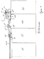
- FIG. 3 is an upper plan view similar to that of FIG. 2 , shown without the hot-melt adhesive applicator.
- FIG. 4 is a perspective view of the driven-belt apparatus, with the belt shown partially in phantom, for urging the zipper flanges against the exterior of the horizontally oriented reclosable packages, in order to assure the quality of the seal by the hot-melt adhesive therebetween.
- FIG. 5 is a cross-sectional view along plane 5 - 5 of FIG. 4 .
- FIGS. 1-3 disclose the apparatus 10 for applying hot-melt adhesive to the zipper flanges.
- the zipper 100 is provided as a continuous length of zipper material traveling in the machine direction, at a selected speed, from a spool 200 (not drawn to scale), typically with the first and second interlocking elements 102 , 104 of the respective first and second zipper profiles 110 , 112 interlocked with each other and with first and second flanges 106 , 108 of the respective first and second zipper profiles 110 , 112 abutting each other.
- Spool 200 is unreeled to provide the zipper 100 in the machine direction.
- a pair of grooved profile guide rollers 212 captures and aligns the interlocked first and second interlocking elements 102 , 104 .
- first pair of opposed pinch rollers 204 , 206 engages first flange 106
- second pair of opposed pinch rollers 208 engages second flange 108 so as to separate or spread the first and second flanges 106 , 108 substantially 180° from each other, while the first and second interlocking elements 102 , 104 remain interlocked with each other.
- the interior walls of first and second flanges 106 , 108 face upwardly and the exterior walls of first and second flanges 106 , 108 face downwardly.
- First pair of opposed pinch rollers 204 , 206 and profile guide roller 212 are mounted on first position adjustment device 216 to adjust and vary the desired position, orientation and alignment of the pinch rollers 204 , 206 and profile guide roller 212 .
- second pair of opposed pinch rollers 208 , 210 and the second (unillustrated) profile guide roller are mounted on second position adjustment device 218 to adjust and vary the desired position, orientation and alignment of the pinch rollers 208 , 210 and second (unillustrated) profile guide roller.
- Zipper 100 passes over roller 220 (which may be grooved in order to align the zipper 100 ) and thereafter passes under hot-melt applicator 222 which sprays hot-melt adhesive downwardly onto the upwardly facing interior walls of first and second flanges 106 , 108 .
- the downward spraying of the hot-melt adhesive is envisioned to increase the long-term performance of the nozzle of the hot-melt applicator 222 .
- hot-melt applicator 222 could apply any number of hot-melt adhesives, such as would be known to those skilled in the art upon review of this disclosure. However, it is particularly envisioned that hot-melt adhesives such as hot-melt, cross-linkable adhesive (such as hot-melt cross-linkable polyurethane reactive adhesive) would be particularly adapted to this method and apparatus, particularly for larger packages or bags with multi-layer paper or woven polypropylene walls.
- hot-melt adhesives such as hot-melt, cross-linkable adhesive (such as hot-melt cross-linkable polyurethane reactive adhesive) would be particularly adapted to this method and apparatus, particularly for larger packages or bags with multi-layer paper or woven polypropylene walls.
- Guide tube 224 includes a tubular interior which captures the interlocked first and second interlocking elements 102 , 104 and further includes a longitudinal slot 226 which guides first and second flanges 106 , 108 back together and directs the first and second flanges 106 , 108 in a direction toward the package 300 , thereby capturing the edge 302 of one of series of horizontally oriented packages 300 that are moving (typically continuously) in the machine direction at a speed equal to that of zipper 100 .
- Edge 302 includes an opening or mouth between two walls of material, such as multi-layer paper or woven polypropylene.
- Edge 302 will form the top of the finished reclosable package, with zipper 100 providing the reclosable characteristics of the mouth thereof.
- First flange 106 is urged against the top wall (with respect to the horizontal orientation of the package 300 illustrated in FIGS. 1-3 ) of package 300 while second flange 108 is urged against the bottom wall of package 300 .
- the walls will ordinarily be referred to as front and rear walls.
- Longitudinal slot 226 may have a width which gradually tapers in order to urge the first and second flanges 106 , 108 together smoothly, while decreasing the risk of snagging.
- Guide tube 224 is mounted on third position adjustment device 230 in order to vary the position, orientation and alignment of guide tube 224 .
- Guides (not shown), with or without vacuum, may be used to position package 300 between the first and second zipper flanges 106 , 108 .
- Zipper 100 along with the packages or bags 300 attached thereto, continues to move in the machine direction at the selected velocity so that first and second flanges 106 , 108 , with edge 302 of package or bag 300 captured therebetween, is introduced to driven-belt apparatus 400 which is illustrated, in part, in the upper right hand corner of FIG. 1 , the upper central portions of FIGS. 2 and 3 , and in further detail in FIGS. 4 and 5 .
- Driven-belt apparatus 400 includes upper and lower forward opposed rollers 402 , 404 and upper and lower rearward opposed rollers 406 , 408 .
- Driven-belt apparatus 400 further includes wedge guides 401 (see FIGS. 1-3 ) on both the upper and lower portions thereof to urge first and second zipper flanges 106 , 108 into position against package 300 .
- At least one of four opposed rollers 402 , 404 , 406 , 408 is powered, but typically one roller in the pair 402 , 404 and another roller in the pair 406 , 408 are powered.
- An upper bar 410 with upper idler rollers 412 is provided and a lower bar 414 with lower idler rollers 416 is likewise provided.
- Upper belt 418 passes around upper forward opposed roller 402 and upper rearward opposed roller 406 , with the lower portion of upper belt 418 being immediately below upper idler rollers 412 .
- Lower belt 420 passes around lower forward opposed roller 404 and lower rearward opposed roller 408 , with the upper portion of lower belt 420 passing immediately above lower idler rollers 416 .
- Upper and lower belts 418 , 420 are shown only partially and in phantom in FIG. 4 . However, belts 418 , 420 are shown in the cross-section view of FIG. 5 .
- Piston arrangement 422 shown in FIG. 4 , allows upper bar 410 to be moved upwardly away from lower bar 412 as required for maintenance, and lowered so as to form the desired nip between upper and lower belts 418 , 420 .
- the nip between upper and lower belts 418 , 420 into which the zipper 100 with edge 302 of package 300 enters between the upper and lower opposed rollers 402 , 404 , creates highly desirable and uniform surface contact among the first and second zipper flanges 106 , 108 , the hot-melt adhesive and the walls of package or bag 300 thereby creating an adhesive connection or bond between the flanges and the package or bag walls which is highly consistent, reliable and strong.
- the driving of upper and lower belts 418 , 420 further moves the packages or bags 300 with the attached zipper 100 in the machine direction. Zipper 100 is subsequently separated between subsequent packages 300 thereby resulting in a plurality of individual packages.
- this apparatus is particularly well-adapted for continuous operation (that is, typically without the need for intermittent movement) through a range of operating speeds.
Abstract
Description
Claims (16)
Priority Applications (2)
| Application Number | Priority Date | Filing Date | Title |
|---|---|---|---|
| US11/891,217 US7674220B2 (en) | 2007-08-09 | 2007-08-09 | Method and apparatus for applying hot-melt adhesive to zipper flanges and applying zipper to packages |
| PCT/US2008/066807 WO2009020704A1 (en) | 2007-08-09 | 2008-06-13 | Method and apparatus for applying hot-melt adhesive to zipper flanges and applying zipper to packages |
Applications Claiming Priority (1)
| Application Number | Priority Date | Filing Date | Title |
|---|---|---|---|
| US11/891,217 US7674220B2 (en) | 2007-08-09 | 2007-08-09 | Method and apparatus for applying hot-melt adhesive to zipper flanges and applying zipper to packages |
Publications (2)
| Publication Number | Publication Date |
|---|---|
| US20090042706A1 US20090042706A1 (en) | 2009-02-12 |
| US7674220B2 true US7674220B2 (en) | 2010-03-09 |
Family
ID=39765060
Family Applications (1)
| Application Number | Title | Priority Date | Filing Date |
|---|---|---|---|
| US11/891,217 Expired - Fee Related US7674220B2 (en) | 2007-08-09 | 2007-08-09 | Method and apparatus for applying hot-melt adhesive to zipper flanges and applying zipper to packages |
Country Status (2)
| Country | Link |
|---|---|
| US (1) | US7674220B2 (en) |
| WO (1) | WO2009020704A1 (en) |
Families Citing this family (3)
| Publication number | Priority date | Publication date | Assignee | Title |
|---|---|---|---|---|
| US5498599A (en) * | 1994-01-21 | 1996-03-12 | Amgen Inc. | Methods for stimulating platelet production |
| WO2009025755A2 (en) * | 2007-08-17 | 2009-02-26 | Illinois Tool Works Inc. | Dual hot melt adhesive systems |
| US7681732B2 (en) * | 2008-01-11 | 2010-03-23 | Cryovac, Inc. | Laminated lidstock |
Citations (11)
| Publication number | Priority date | Publication date | Assignee | Title |
|---|---|---|---|---|
| US4341575A (en) * | 1975-11-03 | 1982-07-27 | Minigrip, Inc. | Means for joining flexible fastener strips to film |
| US4601694A (en) * | 1982-04-16 | 1986-07-22 | Minigrip, Inc. | Thin wall reclosable bag material and method of making same |
| US4620320A (en) * | 1984-12-20 | 1986-10-28 | Kcl Corporation | Substantially leakproof zipper closure for bags and method |
| US4691373A (en) * | 1985-08-05 | 1987-09-01 | Minigrip, Incorporated | Zipper closure with unitary adhesive cover sheet |
| US4812074A (en) * | 1985-08-30 | 1989-03-14 | Minigrip, Inc. | Apparatus for making bag material |
| EP0531701A1 (en) | 1991-08-08 | 1993-03-17 | Kraft Foods, Inc. | In-line application of closure to packaging film |
| US5709915A (en) * | 1995-08-04 | 1998-01-20 | Reynolds Consumer Products, Inc. | Adhesive structure for heat sealing |
| US6131370A (en) * | 2000-02-09 | 2000-10-17 | Illinois Tool Works Inc. | Zipper applied across a film in transverse direction |
| US6216423B1 (en) * | 1997-11-07 | 2001-04-17 | Huntsman Kcl Corporation | Method and apparatus for placing a product in a flexible recloseable container |
| US7093409B2 (en) * | 2000-08-10 | 2006-08-22 | Pactiv Corporation | Method and apparatus for making reclosable plastic bags using a pre-applied slider-operated fastener |
| US7197859B2 (en) * | 2002-03-18 | 2007-04-03 | Frito-Lay North American, Inc. | Vertical stand-up pouch with zipper seal quick change module |
-
2007
- 2007-08-09 US US11/891,217 patent/US7674220B2/en not_active Expired - Fee Related
-
2008
- 2008-06-13 WO PCT/US2008/066807 patent/WO2009020704A1/en active Application Filing
Patent Citations (12)
| Publication number | Priority date | Publication date | Assignee | Title |
|---|---|---|---|---|
| US4341575A (en) * | 1975-11-03 | 1982-07-27 | Minigrip, Inc. | Means for joining flexible fastener strips to film |
| US4372793A (en) * | 1975-11-03 | 1983-02-08 | Minigrip, Inc. | Method of joining flexible fastener strips to flexible web |
| US4601694A (en) * | 1982-04-16 | 1986-07-22 | Minigrip, Inc. | Thin wall reclosable bag material and method of making same |
| US4620320A (en) * | 1984-12-20 | 1986-10-28 | Kcl Corporation | Substantially leakproof zipper closure for bags and method |
| US4691373A (en) * | 1985-08-05 | 1987-09-01 | Minigrip, Incorporated | Zipper closure with unitary adhesive cover sheet |
| US4812074A (en) * | 1985-08-30 | 1989-03-14 | Minigrip, Inc. | Apparatus for making bag material |
| EP0531701A1 (en) | 1991-08-08 | 1993-03-17 | Kraft Foods, Inc. | In-line application of closure to packaging film |
| US5709915A (en) * | 1995-08-04 | 1998-01-20 | Reynolds Consumer Products, Inc. | Adhesive structure for heat sealing |
| US6216423B1 (en) * | 1997-11-07 | 2001-04-17 | Huntsman Kcl Corporation | Method and apparatus for placing a product in a flexible recloseable container |
| US6131370A (en) * | 2000-02-09 | 2000-10-17 | Illinois Tool Works Inc. | Zipper applied across a film in transverse direction |
| US7093409B2 (en) * | 2000-08-10 | 2006-08-22 | Pactiv Corporation | Method and apparatus for making reclosable plastic bags using a pre-applied slider-operated fastener |
| US7197859B2 (en) * | 2002-03-18 | 2007-04-03 | Frito-Lay North American, Inc. | Vertical stand-up pouch with zipper seal quick change module |
Also Published As
| Publication number | Publication date |
|---|---|
| WO2009020704A1 (en) | 2009-02-12 |
| US20090042706A1 (en) | 2009-02-12 |
Similar Documents
| Publication | Publication Date | Title |
|---|---|---|
| DE60115824T2 (en) | Machine for packaging stacks of paper or the like in wrapping films | |
| EP0745533B1 (en) | Method for applying zipper onto a tubular film on a form-fill-and-seal machine | |
| EP0686557B1 (en) | Method of making reclosable plastic bags on a form, fill and seal machine with open zipper profiles | |
| EP1077874B1 (en) | Device for producing re-sealable tubular packaging bags | |
| JP3954794B2 (en) | How to relax stretchable (elastic) webs that have been laminated before packaging | |
| AU611873B2 (en) | A guide mechanism for bag film having fastener elements and a form, fill and seal packaging apparatus | |
| US7674220B2 (en) | Method and apparatus for applying hot-melt adhesive to zipper flanges and applying zipper to packages | |
| DE2819887C2 (en) | Device for producing an arrangement having a carrier tape and flat workpieces arranged on top of one another in scales for storing the workpieces | |
| US11376809B2 (en) | Flexible nozzle for inflation and sealing device | |
| US6942609B2 (en) | Zipper applicator | |
| DE102005025706B3 (en) | Machine for closely-fitting, welded repackaging of folded textile returns in various sizes for re-sale, successively welds edges of semi-tubular packaging material during conveying | |
| KR20160101776A (en) | Packaging method and apparatus | |
| EP0873856B1 (en) | Zipper strip and packaging using it | |
| EP3305515B1 (en) | Device and method for producing a bag packaging | |
| US4282055A (en) | Apparatus for applying adhesive rider strips to the flattened end edges of tube sections or sacks | |
| EP2371527B1 (en) | Device and method for manufacturing (tobacco) bags | |
| DE102020106025B4 (en) | Packaging machine and method for packaging a packaged goods with an outer packaging produced from an upper paper web and a lower paper web | |
| US20090097782A1 (en) | Method for producing perforated zipper for transverse direction zipper applicator | |
| EP0558453B1 (en) | Method of attaching a reclosable closure strap to a package and application device for carrying out the method | |
| DE10121525A1 (en) | Form-and-fill method for making resealable packages comprises feeding hook- pile fastener from roll on to sheet from which package is made and cutting strip of correct height which is welded on to sheet | |
| JP2017518241A (en) | Method and apparatus for applying adhesive to tubular core for the manufacture of paper logs | |
| US7182513B1 (en) | Zipper strip and method of positioning the strip transverse longitudinal axis | |
| EP3204170B1 (en) | Device for cooling of adhesive applied to the surface of bag bodies | |
| CN216568656U (en) | Shoe cover machine | |
| DE10134508A1 (en) | Method for summarizing bags, device for carrying out the method and bag chain, and bag stack chain |
Legal Events
| Date | Code | Title | Description |
|---|---|---|---|
| AS | Assignment |
Owner name: ILLINOIS TOOL WORKS INC., ILLINOIS Free format text: ASSIGNMENT OF ASSIGNORS INTEREST;ASSIGNORS:HOWELL, CLIFTON R.;WALLACE, DAVID C.;CAPLAN, ADAM N.;REEL/FRAME:019730/0361 Effective date: 20070808 Owner name: ILLINOIS TOOL WORKS INC.,ILLINOIS Free format text: ASSIGNMENT OF ASSIGNORS INTEREST;ASSIGNORS:HOWELL, CLIFTON R.;WALLACE, DAVID C.;CAPLAN, ADAM N.;REEL/FRAME:019730/0361 Effective date: 20070808 |
|
| STCF | Information on status: patent grant |
Free format text: PATENTED CASE |
|
| FPAY | Fee payment |
Year of fee payment: 4 |
|
| MAFP | Maintenance fee payment |
Free format text: PAYMENT OF MAINTENANCE FEE, 8TH YEAR, LARGE ENTITY (ORIGINAL EVENT CODE: M1552) Year of fee payment: 8 |
|
| FEPP | Fee payment procedure |
Free format text: MAINTENANCE FEE REMINDER MAILED (ORIGINAL EVENT CODE: REM.); ENTITY STATUS OF PATENT OWNER: LARGE ENTITY |
|
| LAPS | Lapse for failure to pay maintenance fees |
Free format text: PATENT EXPIRED FOR FAILURE TO PAY MAINTENANCE FEES (ORIGINAL EVENT CODE: EXP.); ENTITY STATUS OF PATENT OWNER: LARGE ENTITY |
|
| STCH | Information on status: patent discontinuation |
Free format text: PATENT EXPIRED DUE TO NONPAYMENT OF MAINTENANCE FEES UNDER 37 CFR 1.362 |
|
| FP | Lapsed due to failure to pay maintenance fee |
Effective date: 20220309 |