US7671744B2 - Interrogator and interrogation system employing the same - Google Patents
Interrogator and interrogation system employing the same Download PDFInfo
- Publication number
- US7671744B2 US7671744B2 US11/838,094 US83809407A US7671744B2 US 7671744 B2 US7671744 B2 US 7671744B2 US 83809407 A US83809407 A US 83809407A US 7671744 B2 US7671744 B2 US 7671744B2
- Authority
- US
- United States
- Prior art keywords
- correlation
- rfid
- rfid tag
- interrogator
- band
- Prior art date
- Legal status (The legal status is an assumption and is not a legal conclusion. Google has not performed a legal analysis and makes no representation as to the accuracy of the status listed.)
- Expired - Lifetime, expires
Links
- 238000000034 method Methods 0.000 claims abstract description 138
- 238000012545 processing Methods 0.000 claims abstract description 102
- 230000006870 function Effects 0.000 claims description 43
- 238000012935 Averaging Methods 0.000 claims description 18
- 238000007619 statistical method Methods 0.000 claims description 10
- 229910052751 metal Inorganic materials 0.000 abstract description 229
- 239000002184 metal Substances 0.000 abstract description 229
- 230000035945 sensitivity Effects 0.000 abstract description 29
- 230000002411 adverse Effects 0.000 abstract description 4
- 230000004044 response Effects 0.000 description 167
- 238000010586 diagram Methods 0.000 description 88
- 238000001514 detection method Methods 0.000 description 78
- 239000000463 material Substances 0.000 description 35
- 230000008569 process Effects 0.000 description 32
- 238000004891 communication Methods 0.000 description 27
- 230000005540 biological transmission Effects 0.000 description 25
- 230000009467 reduction Effects 0.000 description 23
- 230000008901 benefit Effects 0.000 description 19
- 239000008393 encapsulating agent Substances 0.000 description 18
- 230000005284 excitation Effects 0.000 description 17
- 230000001965 increasing effect Effects 0.000 description 17
- 238000007726 management method Methods 0.000 description 17
- 230000036961 partial effect Effects 0.000 description 16
- 238000013459 approach Methods 0.000 description 14
- 230000003750 conditioning effect Effects 0.000 description 14
- 238000005516 engineering process Methods 0.000 description 14
- 238000001356 surgical procedure Methods 0.000 description 14
- 238000012360 testing method Methods 0.000 description 13
- 230000002745 absorbent Effects 0.000 description 10
- 239000002250 absorbent Substances 0.000 description 10
- 230000003287 optical effect Effects 0.000 description 10
- 230000001976 improved effect Effects 0.000 description 9
- 239000012212 insulator Substances 0.000 description 9
- 230000002238 attenuated effect Effects 0.000 description 8
- 230000010354 integration Effects 0.000 description 8
- 239000000047 product Substances 0.000 description 8
- 238000003491 array Methods 0.000 description 7
- 230000006872 improvement Effects 0.000 description 7
- 238000004519 manufacturing process Methods 0.000 description 7
- 230000002829 reductive effect Effects 0.000 description 7
- 238000009958 sewing Methods 0.000 description 7
- 238000013068 supply chain management Methods 0.000 description 7
- TZCXTZWJZNENPQ-UHFFFAOYSA-L barium sulfate Chemical compound [Ba+2].[O-]S([O-])(=O)=O TZCXTZWJZNENPQ-UHFFFAOYSA-L 0.000 description 6
- 230000002596 correlated effect Effects 0.000 description 6
- 230000000694 effects Effects 0.000 description 6
- 230000000717 retained effect Effects 0.000 description 6
- 238000001228 spectrum Methods 0.000 description 6
- 239000004593 Epoxy Substances 0.000 description 5
- 241000219146 Gossypium Species 0.000 description 5
- 238000004458 analytical method Methods 0.000 description 5
- 230000000875 corresponding effect Effects 0.000 description 5
- 125000003700 epoxy group Chemical group 0.000 description 5
- 230000001939 inductive effect Effects 0.000 description 5
- 239000000203 mixture Substances 0.000 description 5
- 210000002741 palatine tonsil Anatomy 0.000 description 5
- 229920000647 polyepoxide Polymers 0.000 description 5
- 241000167854 Bourreria succulenta Species 0.000 description 4
- 229920000742 Cotton Polymers 0.000 description 4
- 239000000853 adhesive Substances 0.000 description 4
- 235000019693 cherries Nutrition 0.000 description 4
- 230000001427 coherent effect Effects 0.000 description 4
- 238000009826 distribution Methods 0.000 description 4
- 230000007246 mechanism Effects 0.000 description 4
- 230000003071 parasitic effect Effects 0.000 description 4
- 230000001954 sterilising effect Effects 0.000 description 4
- 238000009825 accumulation Methods 0.000 description 3
- 230000009471 action Effects 0.000 description 3
- 239000008280 blood Substances 0.000 description 3
- 210000004369 blood Anatomy 0.000 description 3
- 230000008859 change Effects 0.000 description 3
- 238000013461 design Methods 0.000 description 3
- 239000003989 dielectric material Substances 0.000 description 3
- 238000005538 encapsulation Methods 0.000 description 3
- 238000001914 filtration Methods 0.000 description 3
- 239000012530 fluid Substances 0.000 description 3
- 230000006698 induction Effects 0.000 description 3
- 238000012423 maintenance Methods 0.000 description 3
- 150000002739 metals Chemical class 0.000 description 3
- 230000002441 reversible effect Effects 0.000 description 3
- 238000005070 sampling Methods 0.000 description 3
- 230000003595 spectral effect Effects 0.000 description 3
- 238000004659 sterilization and disinfection Methods 0.000 description 3
- 230000002123 temporal effect Effects 0.000 description 3
- 230000007704 transition Effects 0.000 description 3
- 238000013519 translation Methods 0.000 description 3
- 206010070245 Foreign body Diseases 0.000 description 2
- 230000004888 barrier function Effects 0.000 description 2
- 230000009286 beneficial effect Effects 0.000 description 2
- 238000012937 correction Methods 0.000 description 2
- 125000004122 cyclic group Chemical group 0.000 description 2
- 238000013016 damping Methods 0.000 description 2
- 238000013480 data collection Methods 0.000 description 2
- 230000003247 decreasing effect Effects 0.000 description 2
- 210000005069 ears Anatomy 0.000 description 2
- 230000005672 electromagnetic field Effects 0.000 description 2
- 230000003203 everyday effect Effects 0.000 description 2
- 239000000835 fiber Substances 0.000 description 2
- 238000002955 isolation Methods 0.000 description 2
- 210000003205 muscle Anatomy 0.000 description 2
- 210000000056 organ Anatomy 0.000 description 2
- 230000035755 proliferation Effects 0.000 description 2
- 230000005855 radiation Effects 0.000 description 2
- 238000011084 recovery Methods 0.000 description 2
- 239000004065 semiconductor Substances 0.000 description 2
- 238000000926 separation method Methods 0.000 description 2
- 238000012163 sequencing technique Methods 0.000 description 2
- 230000007480 spreading Effects 0.000 description 2
- 238000003892 spreading Methods 0.000 description 2
- 230000008093 supporting effect Effects 0.000 description 2
- -1 ultraviolet curables Polymers 0.000 description 2
- 206010002091 Anaesthesia Diseases 0.000 description 1
- 229920001651 Cyanoacrylate Polymers 0.000 description 1
- IAYPIBMASNFSPL-UHFFFAOYSA-N Ethylene oxide Chemical compound C1CO1 IAYPIBMASNFSPL-UHFFFAOYSA-N 0.000 description 1
- CWYNVVGOOAEACU-UHFFFAOYSA-N Fe2+ Chemical compound [Fe+2] CWYNVVGOOAEACU-UHFFFAOYSA-N 0.000 description 1
- 102100028043 Fibroblast growth factor 3 Human genes 0.000 description 1
- 235000009438 Gossypium Nutrition 0.000 description 1
- 102100024061 Integrator complex subunit 1 Human genes 0.000 description 1
- 101710092857 Integrator complex subunit 1 Proteins 0.000 description 1
- 108050002021 Integrator complex subunit 2 Proteins 0.000 description 1
- 101001041669 Oryctolagus cuniculus Corticostatin 1 Proteins 0.000 description 1
- XUIMIQQOPSSXEZ-UHFFFAOYSA-N Silicon Chemical compound [Si] XUIMIQQOPSSXEZ-UHFFFAOYSA-N 0.000 description 1
- 229910000831 Steel Inorganic materials 0.000 description 1
- 241000656145 Thyrsites atun Species 0.000 description 1
- 230000004913 activation Effects 0.000 description 1
- 230000004075 alteration Effects 0.000 description 1
- 230000037005 anaesthesia Effects 0.000 description 1
- 238000002399 angioplasty Methods 0.000 description 1
- 230000003466 anti-cipated effect Effects 0.000 description 1
- 230000000712 assembly Effects 0.000 description 1
- 238000000429 assembly Methods 0.000 description 1
- 230000006399 behavior Effects 0.000 description 1
- 238000012925 biological evaluation Methods 0.000 description 1
- 210000001124 body fluid Anatomy 0.000 description 1
- 230000015556 catabolic process Effects 0.000 description 1
- 239000011248 coating agent Substances 0.000 description 1
- 238000000576 coating method Methods 0.000 description 1
- 239000003086 colorant Substances 0.000 description 1
- 150000001875 compounds Chemical class 0.000 description 1
- 238000002591 computed tomography Methods 0.000 description 1
- 238000012790 confirmation Methods 0.000 description 1
- 238000010276 construction Methods 0.000 description 1
- 239000013078 crystal Substances 0.000 description 1
- NLCKLZIHJQEMCU-UHFFFAOYSA-N cyano prop-2-enoate Chemical class C=CC(=O)OC#N NLCKLZIHJQEMCU-UHFFFAOYSA-N 0.000 description 1
- 238000013481 data capture Methods 0.000 description 1
- 230000007123 defense Effects 0.000 description 1
- 230000007812 deficiency Effects 0.000 description 1
- 230000001934 delay Effects 0.000 description 1
- 230000003111 delayed effect Effects 0.000 description 1
- 238000011161 development Methods 0.000 description 1
- 230000018109 developmental process Effects 0.000 description 1
- 238000003745 diagnosis Methods 0.000 description 1
- 229910003460 diamond Inorganic materials 0.000 description 1
- 239000010432 diamond Substances 0.000 description 1
- 230000004069 differentiation Effects 0.000 description 1
- 239000003814 drug Substances 0.000 description 1
- 230000005684 electric field Effects 0.000 description 1
- 238000004146 energy storage Methods 0.000 description 1
- 230000002708 enhancing effect Effects 0.000 description 1
- 230000007613 environmental effect Effects 0.000 description 1
- 238000011156 evaluation Methods 0.000 description 1
- 230000005669 field effect Effects 0.000 description 1
- 238000011049 filling Methods 0.000 description 1
- 238000010304 firing Methods 0.000 description 1
- 235000013305 food Nutrition 0.000 description 1
- 238000009472 formulation Methods 0.000 description 1
- 230000007274 generation of a signal involved in cell-cell signaling Effects 0.000 description 1
- 239000011521 glass Substances 0.000 description 1
- 230000036541 health Effects 0.000 description 1
- 230000002209 hydrophobic effect Effects 0.000 description 1
- 238000011065 in-situ storage Methods 0.000 description 1
- 238000007689 inspection Methods 0.000 description 1
- 229910000765 intermetallic Inorganic materials 0.000 description 1
- 230000000670 limiting effect Effects 0.000 description 1
- 230000014759 maintenance of location Effects 0.000 description 1
- 230000036244 malformation Effects 0.000 description 1
- 238000005259 measurement Methods 0.000 description 1
- 229910044991 metal oxide Inorganic materials 0.000 description 1
- 150000004706 metal oxides Chemical class 0.000 description 1
- 238000002156 mixing Methods 0.000 description 1
- 238000010295 mobile communication Methods 0.000 description 1
- 238000012986 modification Methods 0.000 description 1
- 230000004048 modification Effects 0.000 description 1
- 238000012544 monitoring process Methods 0.000 description 1
- 238000010943 off-gassing Methods 0.000 description 1
- 230000001151 other effect Effects 0.000 description 1
- 238000004806 packaging method and process Methods 0.000 description 1
- 239000004033 plastic Substances 0.000 description 1
- 239000002985 plastic film Substances 0.000 description 1
- 229920000058 polyacrylate Polymers 0.000 description 1
- 229920001296 polysiloxane Polymers 0.000 description 1
- 238000002360 preparation method Methods 0.000 description 1
- 238000007639 printing Methods 0.000 description 1
- 230000000750 progressive effect Effects 0.000 description 1
- 230000001681 protective effect Effects 0.000 description 1
- 238000011946 reduction process Methods 0.000 description 1
- 238000002310 reflectometry Methods 0.000 description 1
- 238000007493 shaping process Methods 0.000 description 1
- 229910052710 silicon Inorganic materials 0.000 description 1
- 239000010703 silicon Substances 0.000 description 1
- GOLXNESZZPUPJE-UHFFFAOYSA-N spiromesifen Chemical compound CC1=CC(C)=CC(C)=C1C(C(O1)=O)=C(OC(=O)CC(C)(C)C)C11CCCC1 GOLXNESZZPUPJE-UHFFFAOYSA-N 0.000 description 1
- 239000010959 steel Substances 0.000 description 1
- 239000000126 substance Substances 0.000 description 1
- 238000006467 substitution reaction Methods 0.000 description 1
- 239000000758 substrate Substances 0.000 description 1
- 239000013589 supplement Substances 0.000 description 1
- 230000003319 supportive effect Effects 0.000 description 1
- 238000003325 tomography Methods 0.000 description 1
- 230000001052 transient effect Effects 0.000 description 1
- 238000002604 ultrasonography Methods 0.000 description 1
- 230000000007 visual effect Effects 0.000 description 1
- 239000002699 waste material Substances 0.000 description 1
- XLYOFNOQVPJJNP-UHFFFAOYSA-N water Substances O XLYOFNOQVPJJNP-UHFFFAOYSA-N 0.000 description 1
- 210000000707 wrist Anatomy 0.000 description 1
Images


Classifications
-
- G—PHYSICS
- G01—MEASURING; TESTING
- G01S—RADIO DIRECTION-FINDING; RADIO NAVIGATION; DETERMINING DISTANCE OR VELOCITY BY USE OF RADIO WAVES; LOCATING OR PRESENCE-DETECTING BY USE OF THE REFLECTION OR RERADIATION OF RADIO WAVES; ANALOGOUS ARRANGEMENTS USING OTHER WAVES
- G01S13/00—Systems using the reflection or reradiation of radio waves, e.g. radar systems; Analogous systems using reflection or reradiation of waves whose nature or wavelength is irrelevant or unspecified
- G01S13/66—Radar-tracking systems; Analogous systems
-
- A—HUMAN NECESSITIES
- A61—MEDICAL OR VETERINARY SCIENCE; HYGIENE
- A61B—DIAGNOSIS; SURGERY; IDENTIFICATION
- A61B90/00—Instruments, implements or accessories specially adapted for surgery or diagnosis and not covered by any of the groups A61B1/00 - A61B50/00, e.g. for luxation treatment or for protecting wound edges
- A61B90/90—Identification means for patients or instruments, e.g. tags
- A61B90/98—Identification means for patients or instruments, e.g. tags using electromagnetic means, e.g. transponders
-
- G—PHYSICS
- G01—MEASURING; TESTING
- G01S—RADIO DIRECTION-FINDING; RADIO NAVIGATION; DETERMINING DISTANCE OR VELOCITY BY USE OF RADIO WAVES; LOCATING OR PRESENCE-DETECTING BY USE OF THE REFLECTION OR RERADIATION OF RADIO WAVES; ANALOGOUS ARRANGEMENTS USING OTHER WAVES
- G01S13/00—Systems using the reflection or reradiation of radio waves, e.g. radar systems; Analogous systems using reflection or reradiation of waves whose nature or wavelength is irrelevant or unspecified
- G01S13/74—Systems using reradiation of radio waves, e.g. secondary radar systems; Analogous systems
- G01S13/82—Systems using reradiation of radio waves, e.g. secondary radar systems; Analogous systems wherein continuous-type signals are transmitted
- G01S13/825—Systems using reradiation of radio waves, e.g. secondary radar systems; Analogous systems wherein continuous-type signals are transmitted with exchange of information between interrogator and responder
-
- G—PHYSICS
- G01—MEASURING; TESTING
- G01S—RADIO DIRECTION-FINDING; RADIO NAVIGATION; DETERMINING DISTANCE OR VELOCITY BY USE OF RADIO WAVES; LOCATING OR PRESENCE-DETECTING BY USE OF THE REFLECTION OR RERADIATION OF RADIO WAVES; ANALOGOUS ARRANGEMENTS USING OTHER WAVES
- G01S13/00—Systems using the reflection or reradiation of radio waves, e.g. radar systems; Analogous systems using reflection or reradiation of waves whose nature or wavelength is irrelevant or unspecified
- G01S13/87—Combinations of radar systems, e.g. primary radar and secondary radar
- G01S13/878—Combination of several spaced transmitters or receivers of known location for determining the position of a transponder or a reflector
-
- G—PHYSICS
- G06—COMPUTING; CALCULATING OR COUNTING
- G06K—GRAPHICAL DATA READING; PRESENTATION OF DATA; RECORD CARRIERS; HANDLING RECORD CARRIERS
- G06K17/00—Methods or arrangements for effecting co-operative working between equipments covered by two or more of main groups G06K1/00 - G06K15/00, e.g. automatic card files incorporating conveying and reading operations
-
- G—PHYSICS
- G06—COMPUTING; CALCULATING OR COUNTING
- G06K—GRAPHICAL DATA READING; PRESENTATION OF DATA; RECORD CARRIERS; HANDLING RECORD CARRIERS
- G06K7/00—Methods or arrangements for sensing record carriers, e.g. for reading patterns
- G06K7/0008—General problems related to the reading of electronic memory record carriers, independent of its reading method, e.g. power transfer
-
- G—PHYSICS
- G06—COMPUTING; CALCULATING OR COUNTING
- G06Q—INFORMATION AND COMMUNICATION TECHNOLOGY [ICT] SPECIALLY ADAPTED FOR ADMINISTRATIVE, COMMERCIAL, FINANCIAL, MANAGERIAL OR SUPERVISORY PURPOSES; SYSTEMS OR METHODS SPECIALLY ADAPTED FOR ADMINISTRATIVE, COMMERCIAL, FINANCIAL, MANAGERIAL OR SUPERVISORY PURPOSES, NOT OTHERWISE PROVIDED FOR
- G06Q10/00—Administration; Management
- G06Q10/08—Logistics, e.g. warehousing, loading or distribution; Inventory or stock management
- G06Q10/087—Inventory or stock management, e.g. order filling, procurement or balancing against orders
-
- A—HUMAN NECESSITIES
- A61—MEDICAL OR VETERINARY SCIENCE; HYGIENE
- A61B—DIAGNOSIS; SURGERY; IDENTIFICATION
- A61B90/00—Instruments, implements or accessories specially adapted for surgery or diagnosis and not covered by any of the groups A61B1/00 - A61B50/00, e.g. for luxation treatment or for protecting wound edges
- A61B90/08—Accessories or related features not otherwise provided for
- A61B2090/0804—Counting number of instruments used; Instrument detectors
- A61B2090/0805—Counting number of instruments used; Instrument detectors automatically, e.g. by means of magnetic, optical or photoelectric detectors
-
- G—PHYSICS
- G01—MEASURING; TESTING
- G01S—RADIO DIRECTION-FINDING; RADIO NAVIGATION; DETERMINING DISTANCE OR VELOCITY BY USE OF RADIO WAVES; LOCATING OR PRESENCE-DETECTING BY USE OF THE REFLECTION OR RERADIATION OF RADIO WAVES; ANALOGOUS ARRANGEMENTS USING OTHER WAVES
- G01S7/00—Details of systems according to groups G01S13/00, G01S15/00, G01S17/00
- G01S7/02—Details of systems according to groups G01S13/00, G01S15/00, G01S17/00 of systems according to group G01S13/00
- G01S7/40—Means for monitoring or calibrating
Definitions
- the present invention is directed, in general, to communication systems and, more specifically, to an interrogator, method of discerning the presence of an object, and an interrogation system employing the same.
- Asset tracking for the purposes of inventory control or the like is employed in a multitude of industry sectors such as in the food industry, apparel markets and any number of manufacturing sectors, to name a few.
- a bar coded tag or radio frequency identification (“RFID”) tag is affixed to the asset and a reader interrogates the item to read the tag and ultimately to account for the asset being tracked.
- RFID radio frequency identification
- an analogous system may be employed in a medical environment to track equipment such as an Electrocardiogram (“EKG”) machine or other modular patient monitoring equipment.
- the instrument kit contains an assortment of surgical items including hemostats, clamps, forceps, scissors, sponges, and the like, based on the type of surgery to be performed.
- a scrub nurse removes the surgical items from the kit and arranges them on a back table located behind the operating table.
- the surgical items are organized in rows on rolled toweling for ease of access and handling by a surgeon and supporting team.
- the surgical items are often positioned on a “Mayo” stand proximate the operating table, while the unused surgical items remain on the back table.
- all of the surgical items must be carefully counted to, among other things, avoid leaving any surgical items in a patient.
- surgical items are typically counted at least three times during the course of a surgical procedure.
- the first count is performed prior to the start of the procedure; the second count is performed prior to a closure of the patient; the third count is performed at the conclusion of the procedure.
- many more counts of the surgical items often involving different personnel (e.g., a circulating nurse and a scrub nurse), are performed.
- AORN Association of PeriOperative Registered Nurses
- rudimentary systems such as visual records scribbled on whiteboards or other more progressive computer tallying systems to designate the count of the surgical items are often employed.
- the multiple manual counting of surgical items is time consuming, ties up key professional personnel, contributes to surgical suite down time, distracts personnel from the surgical procedure, lengthens the time the patient is exposed to anesthesia leading to an increase in mortality and morbidity risk, is generally distasteful to all involved, and still results in errors wherein materials are left in the patient. It should be quite understandable that the average cost overruns of such delays associated with the personnel, capital equipment and the surgical suite itself can run into the tens of thousands of dollars per procedure. On an annual basis, the loss of productivity associated with the surgical suite is quite sizeable and should be addressed to bolster the bottom line of a medical facility.
- the sponge is typically made of gauze-like material with dimensions often covering a four-inch square or a two-inch by four-inch rectangle.
- sponges were commonly made of cotton, but now a number of filament materials are used.
- a filament of radiopaque material e.g., barium sulfate (“BaSO 4 ”)
- BaSO 4 barium sulfate
- the filament or tab is provided to produce a distinct signature on an x-ray machine for the purpose of determining if a sponge is present in the patient. While this is generally effective, even these filaments or tabs are not 100% effective in aiding the location of the sponges.
- Different researchers report that x-ray methods to supplement manual counting are fallible.
- CT computerized tomography
- ultrasonography may detect the reduced density of a sponge and its characteristic pattern of air or gas bubbles trapped within the sponge.
- RFID tags have survived manufacturing processes that require products to be sterilized for a period of time over 120 degrees Celsius.
- Products are autoclaved while mounted on steel racks tagged with an RFID tag such that a rack identification (“ID”) number and time/date stamp can be automatically collected at the beginning and end of the process as the rack travels through the autoclave on a conveyor.
- ID rack identification
- the RFID tags can be specified to withstand more than 1000 hours at temperatures above 120 degrees Celsius. This is just one example of how RFID tags can withstand the arduous environment including the high temperatures associated with an autoclave procedure, whereas a bar code label is unlikely to survive such treatment.
- RFID tags While identification tags or labels may be able to survive the difficult conditions associated with medical applications, there is yet another challenge directed to attaching an identification element to a surgical item or any small device.
- the RFID tags are frequently attached to devices by employing mechanical techniques or may be affixed with sewing techniques.
- a more common form of attachment of an RFID tag to a device is by bonding techniques including encapsulation or adhesion.
- bonding materials are used in the assembly and fabrication of both disposable and reusable medical devices, many of which are certified to United States Pharmacopoeia Class VI requirements. These products include epoxies, silicones, ultraviolet curables, cyanoacrylates, and special acrylic polymer formulations.
- Epoxies form strong and durable bonds, fill gaps effectively and adhere well to most types of substrates.
- Common uses for medical epoxies include a number of applications which require sterilization compatibility such as bonding lenses in endoscopes, attaching plastic tips to tubing in disposable catheters, coating implantable prosthetic devices, bonding balloons to catheters for balloon angioplasty, and bonding diamond scalpel blades for coronary bypass surgery, to name a few.
- a wide range of such materials are available and some provide high strength bonds which are tough, water resistant, low in outgassing, and dimensionally stable over a temperature range of up to 600 degrees Fahrenheit.
- Some epoxies can withstand repeated sterilization such as autoclaving, radiation, ethylene oxide and cold (e.g., chemical) sterilization methods.
- RFID techniques include “smart labels” in airline baggage tracking and in many stores for inventory control and for theft deterrence.
- the smart labels may combine both RFID and bar coding techniques.
- the tags may include batteries and typically only function as read only devices or as read/write devices.
- Less familiar applications for RFID techniques include the inclusion of RFID tags in automobile key fobs as anti-theft devices, identification badges for employees, and RFID tags incorporated into a wrist band as an accurate and secure method of identifying and tracking prison inmates and patrons at entertainment and recreation facilities.
- RFID tags have been proposed for tracking patients and patient files, employee identification badges, identification of blood bags, and process management within the factories of manufacturers making products for medical practice.
- RFID tags without batteries are smaller, lighter and less expensive than those that are active devices.
- the passive RFID tags are typically maintenance free and can last for long periods of time.
- the passive RFID tags are relatively inexpensive, generally as small as an inch in length, and about an eighth of an inch in diameter when encapsulated in hermetic glass cylinders. Recent developments indicate that they will soon be even smaller.
- the RFID tags can be encoded with 64 or more bits of data that represent a large number of unique ID numbers (e.g., about 18,446,744,073,709,551,616 unique ID numbers). Obviously, this number of encoded data provides more than enough unique codes to identify every item used in a surgical procedure or in other environments that may benefit from asset tracking.
- RFID interrogation systems An important attribute of RFID interrogation systems is that a number of RFID tags should be interrogated simultaneously stemming from the signal processing associated with the techniques of impressing the identification information on the carrier signal.
- a related and desirable attribute is that there is not typically a minimum separation required between the RFID tags. Using an anti-collision algorithm, multiple RFID tags may be readily identifiable and, even at an extreme reading range, only minimal separation (e.g., five centimeters or less) to prevent mutual de-tuning is generally necessary. Most other identification systems, such as systems employing bar codes, usually impose that each device be interrogated separately. The ability to interrogate a plurality of closely spaced RFID tags simultaneously is desirable for applications requiring rapid interrogation of a large number of items.
- RFID tags may be affixed to a variety of diverse objects (also referred to as “RFID objects”) and a presence of the RFID tags may be detected without actually physically viewing or contacting the RFID tag.
- RFID objects also referred to as “RFID objects”
- the parameters for the applications of the RFID systems vary widely, but can generally be divided into three significant categories.
- Another category revolves around an ability to read a significant number of the RFID tags simultaneously (or nearly simultaneously).
- a third category stems from an ability to read the RFID tags reliably at increased ranges or under conditions wherein the radio frequency signals have been substantially attenuated. While significant progress has been made in the area of reading multiple RFID tags almost simultaneously (see, for instance, U.S. Pat. No. 6,265,962 entitled “Method for Resolving Signal Collisions Between Multiple RFID Transponders in a Field,” to Black, et al., issued Jul. 24, 2001, which is incorporated herein by reference), there is still room for significant improvement in the area of reading the RFID tags reliably at increased ranges or under conditions when the radio frequency signals have been substantially attenuated.
- the interrogation systems include multiple interrogators that communicate with a base command unit to track a location of an object.
- the interrogators employ signal processing techniques such as precharging the RFID object, and correlating a reference code with a reply code from the RIFD object using selected techniques to increase a sensitivity of the interrogator, especially for adverse environments.
- the interrogation systems include variations of metal instruments and sponges employed therewith.
- the interrogation system includes metal interrogators capable of discerning the presence of a metal object, especially in a presence of another metal object.
- FIGS. 1 to 14 illustrate system level diagrams of embodiments of interrogation systems constructed according to the principles of the present invention
- FIG. 15 illustrates a functional block diagram of an embodiment of an interrogation system constructed according to the principles of the present invention
- FIG. 16 illustrates a block diagram of an embodiment of a base command unit constructed according to the principles of the present invention
- FIG. 17 illustrates a block diagram of an embodiment of an interrogator constructed according to the principles of the present invention.
- FIGS. 18 to 28 illustrate diagrams of exemplary antennas employable with an interrogation system constructed according to the principles of the present invention
- FIG. 29 illustrates a block diagram of another embodiment of an interrogation system demonstrating the capabilities associated with radio frequency identification according to the principles of the present invention
- FIG. 30 illustrates a block diagram of another embodiment of an interrogator constructed in accordance with the principles of the present invention.
- FIG. 31 illustrates a block diagram of an embodiment of portions of the RFID sensing subsystem of FIG. 30 constructed in accordance with the principles of the present invention
- FIG. 32 illustrates a waveform diagram of an exemplary response from an RFID tag of an RFID object in accordance with the principles of the present invention
- FIG. 33 illustrates a waveform diagram of a spectral response associated with the response from the RFID tag illustrated in FIG. 32 ;
- FIG. 34 illustrates a block diagram of portions of a control and processing subsystem of an interrogator constructed according to the principles of the present invention
- FIG. 35 illustrates a block diagram of an embodiment of portions of a correlation subsystem associated with a control and processing subsystem of an interrogator demonstrating an exemplary operation thereof in accordance with the principles of the present invention
- FIG. 36 illustrates a waveform diagram demonstrating exemplary advantages associated with the correlation subsystem described with respect to FIGS. 34 and 35 ;
- FIG. 37 illustrates a waveform diagram demonstrating the sidelobes associated with the correlation subsystem in accordance with the principles of the present invention
- FIG. 38 illustrates a block diagram of portions of an embodiment of a control and processing subsystem of an interrogator constructed according to the principles of the present invention
- FIG. 39 illustrates a waveform diagram demonstrating an application of a cell averaging constant false alarm rate with an interrogator according to the principles of the present invention
- FIG. 40 illustrates a waveform diagram of a cell under test to a cell average ratio as a function of a cell under test lag using an unfiltered reference in accordance with a constant false alarm rate in accordance with the principles of the present invention
- FIG. 41 illustrates a waveform diagram of a cell under test to a cell average ratio for another constant false alarm rate in accordance with the principles of the present invention
- FIGS. 42 and 43 illustrate diagrams of embodiments of filters employable with a control and processing subsystem of an interrogator constructed according to the principles of the present invention
- FIG. 44 illustrates a waveform diagram of a response from a low pass filter employable with a control and processing subsystem of an interrogator constructed according to the principles of the present invention
- FIG. 45 illustrates a diagram of a filter structure employable with a control and processing subsystem of an interrogator constructed according to the principles of the present invention
- FIGS. 46 and 47 illustrate diagrams of an interrogation sequence in accordance with an interrogator
- FIG. 48 illustrates an embodiment of an interrogation sequence in accordance with an interrogator constructed according to the principles of the present invention
- FIG. 49 illustrates waveform diagrams of an embodiment of an interrogation sequence from an interrogator, along with two RFID tag response waveforms from RFID tags designated Tag A and Tag B in accordance with the principles of the present invention
- FIG. 50 illustrates waveform diagrams of an embodiment of an interrogation sequence from an interrogator, response for an RFID tag, and correlation signals from a correlation subsystem of an interrogator in accordance with the principles of the present invention
- FIG. 51 illustrates waveform diagrams of an embodiment of full RFID tag responses and a partial RFID tag response in accordance with the principles of the present invention
- FIG. 52 illustrates waveform diagrams of an embodiment for a string of modulated binary zeros and for a string of modulated binary ones as encoded using frequency shift keying in accordance with the principles of the present invention
- FIG. 53 illustrates waveform diagrams of an embodiment of reference codes or RFID tag signatures including data and clock signals or information, clock-only signals or information, and data-only signals or information in accordance with the principles of the present invention
- FIG. 54 illustrates a waveform diagram of an embodiment of a non-coherently integrated correlation response for an RFID tag matching a reference code or signature in accordance with an interrogator constructed according to the principles of the present invention
- FIG. 55 illustrates waveform diagrams of an embodiment of a non-coherently integrated correlation response for an RFID tag that matches a reference code or signature, for an RFID tag with a similar reply code to the reference code, and for no RFID tag present in accordance with an interrogator constructed according to the principles of the present invention
- FIGS. 56 and 57 illustrate flow diagrams of embodiments of methods of operating an interrogation system according to the principles of the present invention
- FIGS. 58 and 59 illustrate diagrams of embodiments of an RFID tag according to the principles of the present invention.
- FIG. 60 illustrates pictorial representations of metal instruments (e.g., medical instruments) employable with the interrogation system of the present invention
- FIGS. 61 and 62 illustrate top and side views of an embodiment of a metal instrument including an RFID tag according to the principles of the present invention
- FIG. 63 illustrates a side view of an embodiment of a metal instrument including an RFID tag according to the principles of the present invention
- FIG. 64 illustrates a pictorial representation of an exemplary counting system for surgical sponges
- FIGS. 65 to 68 illustrate pictorial representations of several types of surgical sponges
- FIG. 69 illustrates pictorial representations of RFID tags
- FIGS. 70 to 77 illustrate diagrams of embodiments of a sponge in accordance with the principles of the present invention
- FIGS. 78 and 79 illustrate block diagrams of exemplary environments for application of a metal interrogator in accordance with the principles of the present invention
- FIGS. 80 and 81 illustrate block diagrams of an embodiment of a metal interrogator constructed according to the principles of the present invention
- FIGS. 82 to 89 illustrate diagrams of embodiments of antenna arrays employable with a metal interrogator constructed according to the principles of the present invention
- FIG. 90 illustrates a functional block diagram of portions of an embodiment of a metal interrogator constructed according to the principles of the present invention.
- FIG. 91 illustrates digitized waveform diagrams demonstrating waveforms produced by a metal interrogator in accordance with the principles of the present invention
- FIG. 92 illustrates exemplary waveform diagrams of three sampled responses taken from the same antenna within a short time interval in accordance with the principles of the present invention
- FIG. 93 illustrates waveform diagrams of intra-sample noise reduction that relies upon the fact that the resultant waveform from an induction pulse is an exponential curve in accordance with the principles of the present invention
- FIGS. 94 and 95 illustrate flow diagrams of embodiments of a residual method metal detection process for a metal interrogator in accordance with the principles of the present invention
- FIG. 96 illustrates waveform diagrams of sampled responses from two antennas, which are digitized and sampled, according to the principles of the present invention.
- FIG. 97 illustrates waveform diagrams for sampled responses from two different metal detection antennas in accordance with the principles of the present invention.
- the interrogation systems include multiple interrogators (designated “INT”) with corresponding antennas (designated “ANT”) that define an active area for detecting, without limitation, RFID objects (e.g., objects such as a sponge with an RFID tag attached thereto), metal objects (e.g., objects including metal), and bar coded objects (e.g., objects such as a blood bag with a bar code thereon).
- RFID objects e.g., objects such as a sponge with an RFID tag attached thereto
- metal objects e.g., objects including metal
- bar coded objects e.g., objects such as a blood bag with a bar code thereon.
- the interrogators illustrated with respect to the interrogation systems of FIGS. 1 to 7 include far field antennas.
- the interrogators are located at stations (such as a back table, a soiled consumable (or disposable) and instrument station, a dirty basin station, and an operating station of an operating room).
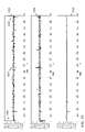
- ones of the interrogators form mobile interrogators with, for instance, an RFID wand (designated “RFID WAND;” see, e.g., FIG. 2 ), a metal wand (designated “MTL WAND;” see, e.g., FIG. 3 ), an integrated RFID and metal wand (designated “RFID/MTL WAND;” see, e.g., FIG. 5 ) or combinations thereof, located at a station such as an operating station.
- selected ones of the mobile interrogators may be integrated RFID and metal interrogator wands (designated “RFID/MTL INT WAND”) chargeable through a charger (designated “CHARGER”).
- mobile interrogators include RFID and metal wands
- other technologies may be employed in conjunction with the mobile interrogators such as, without limitation, bar code, optical, optical recognition, microelectromechanical systems, radio frequency and dot-peening.
- optical scanning may be employed to detect and account for small items such as needles.
- the interrogators are coupled to a base command unit (e.g., wirelessly as illustrated in FIG. 4 ) such as personal computer, a laptop computer, a server, or any computer processing system.
- the base command unit (designated “BCU”) is coupled to another computer system (designated “CS”) such as a hospital information technology system and a display (e.g., a wall mounted display designated “DIS”).
- the base command unit includes control and processing subsystems for the interrogation system.
- the interrogation system may also incorporate multiple interrogators (designated “INT 1 ” and “INT 2 ”) employing different types of technologies that accommodate different technologies such as, without limitation, RFID, metal, bar code, optical, optical recognition, microelectromechanical systems, radio frequency and dot-peening.
- interrogators designated “INT 1 ” and “INT 2 ”
- RFID e.g., RFID, metal, bar code, optical, optical recognition, microelectromechanical systems, radio frequency and dot-peening.
- the function of detecting different types of technologies may be integrated into a single interrogator.
- the interrogation systems can detect, count and account for objects such as, without limitation, RFID objects (e.g., object with an RFID tag), metal objects and bar coded objects (e.g., objects with a bar code).
- the interrogation systems allow an RFID object or other object to be read into the base command unit via an interrogator and reconciled, at a later time, by being read by the same or a different interrogator into the base command unit.
- the base command unit receives signals from the interrogators to track a location of an object, preferably in real time, which may be shown on a display.
- the interrogators are operable with different types of antennas such as, without limitation, near field antennas (designated “ANT NF ”), ring antennas (designated “ANT RING ”), near field antenna arrays (designated “ANT NF ARRAY ”) and bi-static antennas.
- Another problem encountered is the ability to detect and read an RFID object at any location within a defined area.
- One method of accomplishing this function is to specifically place an antenna, for example, over a specific area so that that area may be monitored.
- other RFID objects that may be in areas adjacent to the desired area can also be inadvertently read due to coverage overlap in the antennas thereby generating erroneous data.
- some environments strictly forbid antennas over areas wherein objects need to be detected.
- the dimensions of the specific areas are not standardized and are required in various sizes and shapes that are not defined apriori. Therefore, what is needed is a interrogation system capable of reliably detecting and counting RFID objects in a well defined area while not erroneously counting them in adjacent areas and additionally able to easily define and modify this area both in size and shape.
- FIG. 9 illustrated is a diagram of an interrogation system capable of providing interrogation (such as RFID interrogation) coverage to a specific and well defined area.
- An array of tiles a tile of which is designated “TILE”
- TILE a surface of a table
- Each tile is individually capable of detecting and counting an object (e.g., an RFID object) if the RFID object is placed on or above that tile.
- the array is connected to an interrogator (designated “INT”) via cabling that individually directs each tile to interrogate its specific area and reports the results back to a base command unit via cabling.
- the individual tiles are reconfigurable with respect to each other so that both the shape and size of the active area can be easily changed.
- the active tile (designated “Active Tile”) includes an integrated interrogator (designated “INT”) connected to an antenna (designated “ANT”).
- the interrogator derives prime power (designated “Pwr”) and input commands as well as outputting results (via an input/output bus designated “I/O”) digitally to a controller.
- INT integrated interrogator
- ANT antenna
- Pwr prime power
- I/O input/output bus
- FIG. 11 illustrated is a diagram of an embodiment of an active tile (designated “Active Tile”) illustrating how an interrogator (designated “INT”) is connected directly to an antenna (designated “ANT”).
- INT interrogator
- ANT antenna
- the side of the antenna opposite that side to which the interrogator is connected forms the radiating face of the antenna.
- Multiple tiles can be mounted side by side in various configurations to establish a desired area and size of desired coverage.
- FIG. 12 illustrated is a diagram wherein active tiles (designated “Active Tile”) are individually addressable via a bus (designated “BUS”).
- the active tiles communication via the bus with a controller (designated “CTLR”) that includes a digital multiplexer (designated “DMUX”) connected to a translator (designated “TNLR”), which communicates with a base command unit.
- CTLR controller
- DMUX digital multiplexer
- TNLR translator
- the controller polls the active tiles to obtain the results therefrom and provides a translation for communication with the base command unit.
- FIG. 13 illustrated is a diagram wherein active tiles (designated “Active Tile”) are individually addressable via separate buses (one of which is designated “BUS”).
- the active tiles communicate via their respective bus with a controller (designated “CTLR”) that includes a digital multiplexer (designated “DMUX”) connected to a translator (designated “TNLR”), which communicates with a base command unit.
- CTLR controller
- DMUX digital multiplexer
- TNLR translator
- the controller polls the active tiles to obtain the results therefrom and provides a translation for communication with the base command unit.
- FIG. 14 illustrated is a diagram wherein an antenna of tiles (designated “TILE”) individually communicate via an RF link (one of which is designated “RFL”) to an RF multiplexer (designated “RMUX”) of a controller (designated “CTLR”).
- the controller also includes an interrogator (designated “INT”) and a translator (designated “TNLR”), which communicates with a base command unit.
- the controller transmits/receives RF signals from the tiles, performs the interrogation function, and provides a translation for communication with the base command unit.
- the interrogation system includes a base command unit (designated “BCU”) including an input/output module (designated “I/O module” including, without limitation, a display or monitor, keyboard, mouse and printer), a device management module (designated “DM module” including, without limitation, a user interface, accountable object management, remote scanner/detection management, fault tolerance, external interfaces, continuous diagnostics, maintenance and configuration), an operating system (designated “O/S module” such as an MS Windows operating system), a processor (designated “processor”), and memory (designated “memory” including, without limitation, a hard drive).
- BCU base command unit
- I/O module including, without limitation, a display or monitor, keyboard, mouse and printer
- DM module including, without limitation, a user interface, accountable object management, remote scanner/detection management, fault tolerance, external interfaces, continuous diagnostics, maintenance and configuration
- an operating system designated “O/S module” such as an MS Windows operating system
- processor designated “processor”
- memory
- the base command unit also includes an external computer system interface (designated “CS I/F” including, without limitation, a PCMCIA interface) to external computer systems such as, without limitation, an information technology system or supply chain management system.
- the base command unit also includes a power management module (designated “PM module”) coupleable to an external source of power.
- the base command unit also includes a wand charger (designated “wand charger”) coupleable to a wand when docked.
- the base command unit also includes a remote communications module (designated “RC module”) to communicate with the wand and scan units via, for instance, bluetooth.
- the wand unit represents a mobile interrogator and the scan unit represents a fixed interrogator.
- the wand unit (designated “wand”) and the scan unit (designated “scanner”) include a device management module (designated “DM module”) including, without limitation, device state management and configuration, maintenance interface, fault tolerance, external interfaces and continuous diagnostics.
- the wand and scan units also include an RFID sensing subsystem (designated “RFID S/S”) coupled to an RFID antenna (designated “RFID ANT”) via a radio frequency power amplifier (designated “RF PA”).
- RFID S/S an RFID sensing subsystem
- RFID antenna designated “RFID ANT”
- RF PA radio frequency power amplifier
- the wand and scan units also include a metal sensing subsystem (“metal S/S”) coupled to a metal antenna (designated “metal ANT”) and another sensing subsystem (“other S/S” including, without limitation, bar code, optical, optical recognition, microelectromechanical systems, radio frequency and dot-peening) coupled to another antenna/interface (designated “other ANT/IF”).
- metal S/S metal sensing subsystem
- other S/S including, without limitation, bar code, optical, optical recognition, microelectromechanical systems, radio frequency and dot-peening
- the wand and scan units are detecting or scanning for an RFID object (designated “RFID object” such as, without limitation, a sponge with an RFID tag) via radio frequency (“RF”) energy.
- RFID object such as, without limitation, a sponge with an RFID tag
- RF radio frequency
- the wand and scan units also include a user interface module (designated “UI module”) and a remote communications module (designated “RC module”) to communicate with the base command unit.
- the scan unit also includes a power management module (designated “PM module”) coupleable to an external source of power and the wand unit includes a power management module (designated “PM module”) coupleable to a charger.
- the base command unit includes a processor, a video processor, memory (e.g., hard drive and memory backup), a router (e.g., a 12 port universal serial bus 2.0 router), a power supply, and input/output devices such as a monitor or display, a printer, an audible device, a keyboard and a pointing device.
- a processor e.g., a central processing unit (CPU)
- a video processor e.g., a central processing unit
- memory e.g., hard drive and memory backup
- a router e.g., a 12 port universal serial bus 2.0 router
- input/output devices such as a monitor or display, a printer, an audible device, a keyboard and a pointing device.
- the interrogator includes a metal sensing subsystem (including a metal detection wand assembly and metal detector), an RFID sensing subsystem (including an RFID reader module, fixed RFID antenna or wand assembly, power amplifier, digital and analog assemblies), a host communication and power management module, a power supply and remote communications module such as a wireless interface. While the illustrated interrogator includes RFID and metal sensing subsystems and modules, it should be understood that the interrogator may include other sensing subsystems and modules such as, without limitation, bar code, optical, optical recognition, microelectromechanical systems, radio frequency and dot-peening.
- FIGS. 18 to 28 illustrated are diagrams of exemplary antennas employable with an interrogation system constructed according to the principles of the present invention.
- an object e.g., an RFID object
- the interrogator is scanned over an area where an RFID tag of the RFID object might be located.
- One approach to this problem is to simply use an existing antenna in a monostatic configuration and extend it via radio frequency (“RF”) cabling so that the antenna can in effect be scanned over an area.
- RF radio frequency
- a conventional bistatic antenna using far field antennas is large and the area of detection can also be sufficiently large so as to render it useless for any detection that also requires location information. Therefore, what is needed is an antenna that both provides good location information and maintains good detection sensitivity beyond several inches.
- FIG. 18 illustrated is a diagram of an RFID interrogator (designated “INT”) employing a bistatic antenna configuration where a first antenna (designated “RX ANT”) is connected to a receiver port (designated “RX”) and a second antenna (designated “TX ANT”) is connected to a transmitter port (designated “TX”).
- RX ANT first antenna
- TX ANT second antenna
- TX transmitter port
- FIG. 19 illustrated is an embodiment of a bistatic antenna configuration used with RFID interrogator specifically configured to provide both good detection sensitivity at ranges of several feet while also maintaining good location detection capability.
- a transmit antenna (designated “TX ANT”) is connected to the transmit port (designated “TX”) of the interrogator and is a single antenna about which is placed two (2) receive antennas (designated “RX ANT”) which are then connected to a matching network (designated “MN”) and then to the receive port (designated “RX”) of the interrogator.
- the transmit antenna and receive antennas need not be of the same type as illustrated in this embodiment.
- FIGS. 20 to 26 illustrated are embodiments of antenna configurations constructed according to the principles of the present invention.
- a curved metallic structure contains a single continuous element (designated “CE”). This structure, therefore, places a much higher field strength for detection within the curved structure than without.
- a mounting structure such as a pole supports the antenna.
- FIG. 22 the curved metallic structure has been replaced by straight surfaces. This antenna configuration offers a more open configuration so that the object can be logged at greater distances.
- the continuous element discussed above is replaced by individual discrete elements (designated “DE”) and mounted to the curved conducting surfaces.
- individual discrete elements designated “DE” are located on straight conducting surfaces.
- a closed metal structure having an open top (designated “OT”) and open bottom has mounted onto its inner surfaces discrete antenna elements (designated “DE”).
- OTP open top
- DE discrete antenna elements
- FIGS. 27 and 28 illustrated are other embodiments of antenna configurations constructed according to the principles of the present invention.
- the antenna configurations may also detect a direction by which that RFID object passed therethrough.
- Applications of this added capability include the ability to accept or log in an object by placing the object therethrough in one direction and rejecting or logging out an object by placing the object therethrough in the opposite direction. Other applications for this added capability are comprehended herein.
- the antenna configuration is a generally cylindrical metallic structure open at both ends (one of which is designated “END”) and includes two bands of antenna elements (designated “AEL”), which may be either continuous or discrete. Additionally, an RF barrier (designated “RFB”) is also included so that radiation from one antenna element (or set thereof) does not impinge or excite the other antenna element (or set thereof). Therefore, an object passing through the structure is detected first by one antenna element and then the other at different times, defining uniquely the direction of the RFID object.
- END generally cylindrical metallic structure open at both ends
- AEL antenna elements
- RFID RF barrier
- the cylindrical shape discussed above is replaced by a generally square shape open at both ends (one of which is designated “END”).
- the antenna elements (designated “AEL”) also encompass the structure and are also separated by an RF barrier (designated “RFB”).
- AEL antenna elements
- RFID RF barrier
- the exemplary embodiments of the antennas introduced herein are provided for illustrative purposes only and other embodiments that include arrays for both transmit and receive antennas as well as antennas mounted in different configurations with respect to each other to achieve specific desirable properties such as that discussed above for specific applications are well within the broad scope of the present invention.
- the interrogation system includes an interrogator configured to detect an object at a first time and a second time, and a base command unit is configured to receive signals from the interrogator to track a location of the object, advantageously in real time.
- the interrogation system includes a first fixed interrogator, located at a first station, configured to detect an object at a first time, a second fixed interrogator, located at a second station, configured to detect the object at a second time, and a mobile interrogator, located at a third station, configured to detect the object at a third time.
- a base command unit of the interrogation system is configured to receive signals from the first and second fixed interrogators and the mobile interrogator to track a location of the object, advantageously in real time.
- the base command unit may be coupled to a display to show a location of the object and communicate with another computer system.
- the object is selected from the group consisting of a radio frequency identification object, a radio frequency object, a metal object, a bar coded object, a microelectromechanical systems object, an optical recognition object and a dot-peening object.
- the interrogators employ antennas selected from the group consisting of far field antennas, near field antennas, near field antenna arrays, ring antennas and bi-static antennas.
- the object may be a radio frequency identification object in the form of a sponge with a radio frequency identification tag.
- ones of the interrogators are radio frequency identification interrogators and the object is a radio frequency identification object and the interrogation system further includes another interrogator configured to detect a different object.
- the base command unit can receive signals from the another interrogator to track a location of the different object.
- ones of the interrogators are an integrated radio frequency identification and other interrogator configured to detect a radio frequency identification object and a different object.
- the base command unit is configured to receive signals from the interrogator to track a location of the radio frequency identification and different objects.
- the base command unit is a laptop computer. Additionally, the base command unit may include an input/output device, a device management module, an operating system, a processor, a memory, an external computer system interface, a power management module and a remote communications module. Also, ones of the interrogators may include a device management module, a sensing subsystem, a power management module, a remote communications module and a user interface module. In applications wherein the object is a radio frequency identification object, ones of the interrogators generate radio frequency energy in accordance with a radio frequency identification sensing subsystem and a radio frequency power amplifier to detect the radio frequency identification object. Additionally, the interrogation system may include a charger for the mobile interrogator mentioned above.
- the interrogation system includes an interrogator 2915 including an RFID sensing subsystem 2920 and a control and processing subsystem 2930 that energizes an RFID tag 2905 and then receives, detects and decodes the encoded RF energy (reflected or transmitted) from the RFID tag 2905 .
- the control and processing subsystem 2930 provides overall control of the functions of the interrogator 2915 as well as any reporting functions.
- the interrogator 2915 may also include a user interface, communications subsystem, a power source and other subsystems as described above.
- the interrogation system may be employed with multiple RFID objects and with different types of RFID tags.
- the RFID tags may be passive, passive with active response, and fully active.
- the transmitted energy provides a source to charge an energy storage device within the RFID tag.
- the stored energy is used to power a response from the RFID tag wherein a matching impedance and thereby a reflectivity of the RFID tag is altered in a coded fashion of ones (“1”) and zeros (“0”).
- the RFID tag will also contain a battery to facilitate a response therefrom.
- the battery can simply be used to provide power for the impedance matching/mismatching operation described above, or the RFID tag may even possess an active transmitting function and may even respond at a frequency different from a frequency of the interrogator.
- Any type of tag e.g., RFID tag
- the RFID objects may include more than one RFID tag, each carrying different information (e.g., object specific or sensors reporting on the status of the object) about the RFID object.
- the RFID tags may also include more than one integrated circuit, each circuit including different coded information for a benefit of the interrogation system.
- the interrogator includes a metal sensing subsystem 3005 , a metal sensing antenna interface 3010 , a metal sensing antenna 3015 , an RFID sensing subsystem 3020 , an RFID sensing antenna interface 3030 , an RFID sensing antenna 3035 and a control and processing subsystem 3040 . While the illustrated embodiment provides for an integrated metal and RFID detection capability, those skilled in the art should understand that portions of the interrogator may be omitted or rendered inactive to provide a metal or RFID interrogator. Additionally, different types of sensing subsystems may be incorporated into the interrogator to detect other types of objects, as well.
- the metal sensing subsystem 3005 includes a metal sensing digital-to-analog converter (“DAC”) 3006 , a metal sensing transmit amplifier 3007 , a metal sensing receive amplifier 3008 and a metal sensing analog-to-digital converter (“ADC”) 3009 .
- the metal sensing antenna interface 3010 includes a metal sensing transmit conditioning filter 3011 and a metal sensing receive conditioning filter 3012 .
- the metal sensing antenna 3015 includes a metal sensing transmit antenna 3016 and a metal sensing receive antenna 3017 .
- the RFID sensing subsystem 3020 includes an RFID sensing DAC 3021 , an RFID sensing transmit selector switch 3022 , a first RFID sensing transmit amplifier 3023 , a second RFID sensing transmit amplifier 3024 , a first RFID sensing receive amplifier 3025 , a second RFID sensing receive amplifier 3026 , an RFID sensing receive selector switch 3027 and an RFID sensing ADC 3028 .
- the RFID sensing antenna interface 3030 includes first and second RFID sensing transmit conditioning filters 3031 , 3032 and first and second RFID sensing receive conditioning filters 3033 , 3034 .
- the RFID sensing antenna 3035 includes first and second RFID sensing transmit antennas 3036 , 3037 and first and second RFID sensing receive antennas 3038 , 3039 . “HI band” and “LO band” capabilities are present to accommodate the wide frequency range necessary to detect the various types of RFID tags.
- a mixing or heterodyning function may be included within the RFID sensing ADC 3028 or the RFID sensing DAC 3021 functions. These techniques are known to those skilled in the pertinent art and may be employed to translate signal processing to a more desirable frequency range thereby allowing less expensive or more readily available components to be used. Additionally, the specific nature and function of the first and second transmit conditioning filters 3031 , 3032 and first and second RFID sensing receive conditioning filters 3033 , 3034 may vary depending on the specific algorithms employed for control and processing and for signal generation and recovery. Also, some embodiments may not require some or all of the filters shown.
- control and processing subsystem 3040 may be a software defined structure that allows features and functions of the interrogator to be easily modified or tailored by altering software functions.
- the control and processing subsystem 3040 employs a crystal oscillator to provide a precise frequency reference for both the metal and RFID sensing subsystems 3005 , 3020 .
- the control and processing subsystem 3040 generates a metal sensing digital excitation signal based on a metal sensing mode of operation selected and provides this signal to the metal sensing DAC 3006 .
- the metal sensing digital excitation signal may be in the form of a continuous tone.
- the digital excitation signal may vary in amplitude, frequency, or phase and may also be of a pulsed nature wherein the waveform duty cycle is less than 100 percent.
- the frequency of the metal sensing digital excitation signal may generally be in the range of five to 100 kilohertz (“kHz”). Different waveforms may be used to optimize a detection of both ferrous and non-ferrous metals. These waveforms may be selected for different sizes and masses of metals and for metals at different locations and depths within a patient. Algorithmic information employed in generating these excitation signals may be part of the control and processing subsystem 3040 .
- the metal sensing DAC 3006 converts the metal sensing digital excitation signal into an analog signal that, except for its amplitude, is the metal sensing transmit signal.
- the analog signal is provided to the metal sensing transmit amplifier 3007 , which amplifies the analog signal to a correct amplitude for transmission.
- the output of the metal sensing transmit amplifier 3007 is provided to the metal sensing transmit conditioning filter 3011 , which sufficiently attenuates all out-of-band signals and provides a proper impedance match to the metal sensing transmit antenna 3016 .
- the metal sensing transmit antenna 3016 launches the metal sensing transmit signal.
- a metal object present in the vicinity of the metal sensing transmit antenna 3016 and the metal sensing transmit signal will generate a metal sensing return signal wherein the metal sensing return signal may be based on a change in a field characteristic of the metal sensing transmit signal.
- the field characteristic may be altered in the vicinity of the metal object such that a distinctive metal sensing receive signal impinges on and excites the metal sensing receive antenna 3017 .
- the output of the metal sensing receive antenna 3017 is provided to the metal sensing receive conditioning filter 3012 , which sufficiently attenuates all out-of-band energy and provides a proper impedance match between the metal sensing receive antenna 3017 and the metal sensing receive amplifier 3008 .
- the metal sensing receive amplifier 3008 amplifies the metal sensing receive signal to a level sufficient for processing and provides it to the metal sensing ADC 3009 .
- the metal sensing ADC 3009 provides a metal sensing digital signal, proportional to the metal sensing receive signal, to the control and processing subsystem 3040 , which determines if the metal sensing digital signal has a signature representing a presence of a metal object in the vicinity of the metal sensing antenna 3015 .
- the control and processing subsystem 3040 generates an RFID sensing digital excitation signal based on an RFID mode of operation selected and outputs this signal to the RFID sensing DAC 3021 .
- the RFID sensing digital excitation signal may be in the form of a code that excites and energizes an RFID object present including an RFID tag.
- the carrier frequency associated with this code may be in one of two frequency bands. A first frequency band may be centered around 133-135 kHz and is designated as the “LO band.” A second frequency band may be centered around 10-13 megahertz (“MHz”) and is designated the “HI band.” Alternatively, a “HI band” around 902-928 MHz may also be employed.
- the 133-135 kHz and the 10-13 MHz bands may be combined in the “LO band” and some specific implementations may require only a single band.
- a frequency band is selected based on the RFID mode of operation selected. Each frequency band corresponds to different types of RFID tags present, which may be based on its size or other factors. Of course, the broad scope of the present invention is not limited to a particular frequency band.
- algorithmic information to generate the RFID sensing digital excitation signal is contained in the control and processing subsystem 3040 .
- the RFID sensing DAC 3021 converts the RFID sensing digital excitation signal into an analog signal that, except for amplitude, is the RFID sensing transmit signal.
- the RFID sensing transmit signal is provided to the RFID sensing transmit selector switch 3022 , which is controlled by the control and processing subsystem 3040 .
- the RFID sensing transmit selector switch 3022 directs the RFID sensing transmit signal to the first RFID sensing transmit amplifier 3023 or the second RFID sensing transmit amplifier 3024 , respectively, based on whether the RFID sensing transmit signal is “HI band” or “LO band.”
- the first RFID sensing transmit amplifier 3023 and the second RFID sensing transmit amplifier 3024 increase the amplitude of the “HI band” and “LO band” signals to a correct amplitude for transmission.
- the first RFID sensing transmit amplifier 3023 provides the “HI band” signal to the first RFID sensing transmit conditioning filter 3031 and the second RFID sensing transmit amplifier 3024 provides the “LO band” signal to the second RFID sensing transmit conditioning filter 3032 .
- the first and second RFID sensing transmit conditioning filters 3031 , 3032 employ differing center frequencies and sufficiently attenuate associated out-of-band signals. Additionally, they provide a proper impedance match to their respective first or second RFID sensing transmit antennas 3036 , 3037 , which launch their respective RFID sensing transmit signals.
- An RFID object including an RFID tag, in the vicinity of the first or second RFID sensing transmit antenna 3036 , 3037 generates an RFID sensing return signal.
- the RFID sensing return signal impinges on and excites the appropriate first or second RFID sensing receive antenna 3038 , 3039 , respectively, to provide an RFID sensing receive signal.
- An output of the first or second RFID sensing receive antenna 3038 , 3039 is provided to the first or second RFID receive conditioning filter 3033 , 3034 , respectively.
- the first or second RFID receive conditioning filter 3033 , 3034 sufficiently attenuates the out-of-band energy and provides a proper impedance match between the first or second RFID sensing receive antenna 3038 , 3039 and the first or second RFID sensing receive amplifier 3025 , 3026 , respectively.
- the first or second RFID sensing receive amplifier 3025 , 3026 amplifies the small RFID sensing receive signal to a level sufficient for processing and provides an amplified RFID sensing receive signal to the RFID sensing receive selector switch 3027 , which is controlled by the control and processing subsystem 3040 .
- the control and processing subsystem 3040 selects the appropriate reception path through the RFID sensing receive selector switch 3027 for input to the RFID sensing ADC 3028 , based on the excitation signal transmitted.
- the RFID sensing ADC 3028 provides an RFID sensing digital signal, proportional to the RFID sensing receive signal, to the control and processing subsystem 3040 , which determines if the RFID sensing receive signal has a signature representing a presence of an RFID object in the vicinity of the RFID sensing antenna 3035 .
- FIG. 31 illustrated is a block diagram of an embodiment of portions of the RFID sensing subsystem 3020 of FIG. 30 constructed in accordance with the principles of the present invention.
- the illustrated embodiment and related description is directed to the “Hi band” signals.
- the principles described herein are equally applicable to the “LO band” signals.
- the illustrated embodiment provides an exemplary RFID sensing transmit amplifier (e.g., the first RFID sensing transmit amplifier 3023 ) of the RFID sensing subsystem 3020 of FIG. 30 and will hereinafter be described with continuing reference thereto.
- the first RFID sensing transmit amplifier 3023 includes first and second amplifiers 3052 , 3062 , a mixer 3056 and an oscillator 3058 .
- the first amplifier 3052 (acting as a buffer and amplifier) receives a signal from the RFID sensing transmit selector switch 3022 and provides a modulated signal to the mixer 3056 .
- the oscillator 3058 receives a control signal from the control and processing subsystem 3040 and provides a carrier signal to the mixer 3056 to set an RF carrier frequency.
- the control signal determines the basic RF carrier frequency that can change according to a specific air interface specification. For example, the United States ultra-high frequency (“US UHF”) standard specifies a basic carrier frequency between 902 and 928 MHz.
- US UHF United States ultra-high frequency
- the mixer 3056 adds the modulated signal to the carrier signal and provides a mixed signal to the second amplifier 3062 .
- the second amplifier 3062 is a variable gain amplifier whose output signal amplitude is determined by a gain control signal from the control and processing subsystem 3040 .
- the gain control signal sets an output power level of the signal from the second amplifier 3062 .
- the signal from the second amplifier 3062 is provided to the first RFID sensing transmit conditioning filter 3031 .
- the RFID sensing subsystem 3020 otherwise operates as set forth above with respect to FIG. 30 .
- the modulated signal may be applied directly to an output amplifier by a gain control signal and thereby eliminate the need for the mixer 3056 .
- FIG. 32 illustrated is a waveform diagram of an exemplary response from an RFID tag of an RFID object in accordance with the principles of the present invention.
- the exemplary response includes recorded transmissions 3215 and backscatter return signals 3220 from the RFID tag under docile conditions. Under docile conditions, the response from the RFID tag is quite strong and substantially above the ambient noise level 3210 and an interrogator can more readily detect the response on an individual bit-by-bit basis.
- FIG. 33 illustrated is a waveform diagram of a spectral response associated with the response from the RFID tag illustrated in FIG. 32 .
- the spectral response provides a strong signal in accordance with the response from the RFID tag under docile conditions.
- the signal is essentially in two distinct components.
- the first component is a strong backscatter return 3310 , which is strongest in amplitude and at the center of the response.
- the second component is the lower amplitude frequency shift keying (“FSK”) modulation backscatter return 3315 consisting of a series of peaks.
- FSK frequency shift keying
- an interrogator and interrogation system constructed according to the principles of the present invention accommodates reliable identification of the RFID tag under docile conditions and in hostile environments.
- the gain would be 18.06 dB.
- an RFID tag with a 96 bit tag ID code and an eight bit preamble and 16 bit cyclic redundancy check (“CRC”) is used for the correlation, then the gain would be 20.79 dB.
- the gain corresponds to an improvement in the signal to noise ratio (“SNR”) as set forth above.
- FIG. 34 illustrated is a block diagram of portions of a control and processing subsystem of an interrogator constructed according to the principles of the present invention.
- the control and processing subsystem includes a correlation subsystem 3405 and a decision subsystem 3410 . While in the illustrated embodiment the correlation subsystem and the decision subsystem form a portion of the control and processing subsystem such as within a digital signal processor thereof, those skilled in the art should understand that the subsystems may be discrete subsystems of the control and processing subsystem of the interrogator or located in other locations of an interrogation system.
- the interrogator may employ a correlation operation to correlate between reference codes (generally designated 3415 ) corresponding to reply codes (generally designated 3425 ) from the RFID tags of RFID objects and subsequently received and digitized reply codes from the RFID tags to enhance a sensitivity of the interrogator.
- the reply codes are typically generated as complex I+jQ signals, where I signifies the in phase portion of the signal and Q signifies its quadrature counterpart.
- the reference codes may be scanned in during the initialization stage or derived synthetically as hereinafter described. To derive the reference code synthetically, the amplitude, phase and delay (e.g., timing of a response to an excitation signal) information of a particular type of RFID tag may be employed by the interrogator to derive the synthetic reference code.
- the correlation occurs in a correlator 3430 wherein the reply code is correlated (e.g., compared or matched) with the reference code during a post-initialization stage of operation.
- the correlation is mathematically analogous to a convolution operation. For a better understanding of convolution theory, see “An Introduction to Statistical Communication Theory,” by John B. Thomas, published by John Wiley & Sons, Inc. (1969), which is incorporated herein by reference.
- a stream of incoming data in the form of a response to the interrogator (e.g., corresponding to responses in the form of reply codes from the RFID tags) is correlated against preloaded reference codes loaded into a reference code database in time.
- samples of the incoming data may be gated in a block by the interrogator and then the data is correlated in block manner against the reference codes.
- a gating process is employed to gate the incoming data properly. Under such circumstances, apriori knowledge of a timing of the responses from the RFID tag in connection with a query by the interrogator better serves the process of gating the block of incoming data (e.g., the responses) from the RFID tags.
- any known delay in the responses from the RFID tags can be preloaded in the interrogator during the initialization stage.
- An external sensor such as a position sensor (e.g., inertial sensor) may be employed by the interrogator to aid the correlation subsystem in predicting the timing of a response from the RFID tag.
- a synchronization pulse (e.g., derived from the transmit excitation signal) may also be employed to better define a timing of a response from an RFID tag.
- the output of the correlator 3430 representing individual correlations of the reference code with incoming data is summed in a summer 3435 providing a correlation signal to improve the signal to noise ratio of the correlated signal.
- the correlation signal from the summer 3435 is typically input into a threshold detector 3440 within the decision subsystem 3410 to verify a presence of an RFID tag.
- the threshold detector 3440 typically compares the correlation signal with at least one threshold criteria or value (also referred to as threshold).
- the threshold may be fixed or dynamically determined. In one exemplary embodiment, where only a single threshold is present, an RFID tag is declared present if the correlation signal from the summer 3435 exceeds the threshold, and not present if the converse is true. In other embodiments, multiple thresholds may be used to indicate various levels of probabilities as to the likelihood that an RFID tag is present or not. This information may then be used to initiate selected or additional search modes so as to reduce remaining ambiguities.
- a tracking of the reply codes may suggest that the reply code is early, prompt or late. If the tracking suggests that the reply code is prompt (prompt output greater than early and later output), then a gating function is properly aligned to provide a significant correlator output. If the tracking suggests that the reply code is early, then the early correlator output is significant as compared to the late correlator output and the correlation subsystem 3405 is tracking too early and the requisite adjustment may be performed. An opposite adjustment may be performed if the tracking suggests that the reply code is late.
- Another approach is to use a tracking loop that uses past successful detection performance to establish a gating process for subsequent correlations.
- relating to the correlation of the reply codes from the RFID tags is to perform Fast Fourier Transforms (“FFTs”) on both the reference code and a gated sample of the reply codes from the RFID tags. Then, a convolution operation in “Fourier Space” may be performed employing the convolution theorem. The convolution theorem states that the convolution of two functions is the product of the Fourier transforms thereof.
- An output of the correlation operation is typically envelope detected and several outputs may be averaged in a summing operation that preserves time characteristics of each individual detection.
- U.S. Publication No. 2005/0201450 the “450 Publication), entitled “Interrogator and Interrogation System Employing the Same,” to Volpi, et al., filed Mar. 3, 2005, which is incorporated herein by reference.
- FIG. 35 illustrated is a block diagram of an embodiment of portions of a correlation subsystem associated with a control and processing subsystem of an interrogator demonstrating an exemplary operation thereof in accordance with the principles of the present invention.
- a technique referred to as a “corner turning memory” is used in accordance with the correlation subsystem allowing a summing and averaging process for multiple correlations.
- An output of a correlator is read into memory by rows (one of which is designated 3510 ) with each row designating a single correlation. Then an output from the summing process (which embodies the memory or a function thereof) is generated by summing across individual columns (generally designated 3515 , hence the name corner turning) applying an appropriate scaling factor.
- An output from the memory represents an average of “P” outputs of the correlation subsystem wherein “P” is the number of rows in the corner turning memory. Assuming a signal is located in every row of the corner turning memory, the improvement in signal to noise ratio (“SNR”) is increased by the square root of “P.”
- SNR signal to noise ratio
- a conventional waveform 3615 represents the probability of detection for a given carrier to noise ratio (“C/No”) of a conventional reader reading at least one out of 100 possible attempts.
- C/No carrier to noise ratio
- a total of 100 trials were averaged in accordance with the correlation subsystem and an improved waveform 3610 represents the increased probability of detection for a given C/No of an interrogator thereby demonstrating an improvement in SNR of 28.06 dB.
- EPC electronic product code
- a purpose of the correlation operation is to determine whether or not the output or averaged output of the interrogator represents a presence of an RFID tag.
- a threshold detector as herein described interprets a correlation signal from the correlation subsystem and provides a decision if the output is of sufficient quality to indicate if an RFID tag is present or not and, if indeterminate, to perform a “deeper” or more “focused” search.
- the correlation includes a major peak 3710 (referred to as “prompt”) and two smaller peaks (generally referred to as “early” 3715 and “late” 3720 ) about the major peak.
- prompt major peak
- early two smaller peaks
- the SNR will be raised to a level wherein substantially unambiguous detection occurs.
- the reply code of an RFID tag is not being detected, but the interrogator is detecting a change in ambient noise that substantially increases the probability that an RFID tag is indeed present. For example, sampling in all three regions and having the noise level be the same is a good indication that an RFID tag is not present and therefore that the sample should be discarded. However, sampling in all three areas and finding that the early and late levels are about equal and the middle level is larger is a good indication that a response from an RFID tag is in fact present and that this sample should be added into the averaging function. Clearly discarding samples that do not pass the early/late noise test will certainly discard data of actual RFID tags.
- control and processing subsystem can maintain a running total of how many samples were discarded so that the number of samples averaged will remain valid.
- a tracking of the reply codes may suggest that the reply code is early, prompt or late. If the tracking suggests that the reply code is prompt (prompt output greater than early and late output), then a gating function is properly aligned to provide a significant correlator output. If the tracking suggests that the reply code is early, then the early correlator output is significant as compared to the late correlator output and the correlation subsystem is tracking too early and the requisite adjustment may be performed. An opposite adjustment may be performed if the tracking suggests that the reply code is late.
- Another approach is to use a tracking loop that uses past successful detection performance to establish a gating process for subsequent correlations.
- FFTs are performed on both the reference code and a gated sample of the reply codes from the RFID tags.
- a convolution operation in “Fourier Space” may be performed employing the convolution theorem.
- the convolution theorem states that the convolution of two functions is the product of the Fourier transforms thereof.
- An output of the correlation operation is typically envelope detected and several outputs may be averaged in a summing operation that preserves time characteristics of each individual detection.
- FIG. 38 illustrated is a block diagram of portions of an embodiment of a control and processing subsystem of an interrogator constructed according to the principles of the present invention.
- the correlation subsystem of the control and processing subsystem correlates using multiple “a” values and then selects a correlation signal yielding the largest correlation value.
- the resultant is then run through an initial constant false alarm rate (“CFAR”) subsystem whose principle function is to decide whether an RFID tag of an RFID object has fired. Secondarily, it is advantageous to filter out burst interference signals from the correlation signals.
- the correlation signals that pass the initial detection (“D-CFAR”) subsystem then enter a decision subsystem.
- D-CFAR initial detection
- the next step is to align the correlation signals so the maximum response lag is at lag 0 .
- An automatic gain control (“AGC”) correction is also applied wherein the signal is normalized to have a peak power of one (at lag 0 ) and then the other lags are normalized by the same constant. This has the effect of making the correlation signals have the same weight in the subsequent steps.
- AGC automatic gain control
- the correlation signals are then envelope detected when employing noncoherent multiple tag response integration.
- the result is passed into an array of low pass filters (“LPF”).
- LPF filter outputs are fed into a final detection CFAR (“D-CFAR”) subsystem that makes the final decision as to whether the RFID tag is present and an identification CFAR (“I-CFAR”) subsystem that decides if the right RFID tag is present, given a detection from the final D-CFAR subsystem.
- D-CFAR final detection CFAR
- I-CFAR identification CFAR
- FIG. 39 illustrated is a waveform diagram demonstrating an application of a cell averaging constant false alarm rate with an interrogator according to the principles of the present invention. More particularly, the waveform diagram demonstrates an application of a cell averaging CFAR to RFID detection wherein an analog to digital sample timing is setup to produce 16 samples per bit.
- the temporal sidelobe structure seen is a consequence of the frequency shift keying (“FSK”) backscatter modulation used in autoID tags. Absent a strong correlation response, the central spike will not be seen.
- FSK frequency shift keying
- a basic idea of the cell averaging CFAR is to average responses at lag values of ⁇ 64, ⁇ 48, ⁇ 32, ⁇ 16, 32, 48, 64 ⁇ with respect to the central 0 lag point and use this as a threshold for testing the central lag for signal presence.
- the central cell is called the cell under test (“CUT”).
- the average of the cells used to obtain the threshold is called the cell average (“CA”).
- FIG. 40 illustrated is a waveform diagram of a cell under test to a cell average ratio as a function of a cell under test lag using an unfiltered reference in accordance with a constant false alarm rate in accordance with the principles of the present invention.
- the ratio increases in the neighborhood of the central peak.
- the big ears at ⁇ 6 & 8 lags are an artifact of the test signal used being unfiltered and will tend to disappear with real signals.
- the above D-CFAR subsystem decides whether an RFID tag is present.
- FIG. 41 illustrated is a waveform diagram of a cell under test to a cell average ratio for another constant false alarm rate in accordance with the principles of the present invention.
- the current average lags are ⁇ 56, ⁇ 40, ⁇ 24, ⁇ 8, 8, 24, 40, 56 ⁇ . These lags yield small correlation values when the signal is present and so act more like a noise level reference. Again, this D-CFAR subsystem decides whether an RFID tag is present.
- the initial D-CFAR subsystem has a gain setup so that the correlation signal passes, even if it is pretty weak, but at the cost of increased false alarm rates. Occasionally, the correlation signal will pass in noise.
- the final D-CFAR subsystem has had the benefit of some filtering from the LPF array and so has its gain value tuned to a larger value so as to have a low false alarm rate. When it declares a detection, the I-CFAR subsystem declared the right RFID tag.
- FIG. 42 illustrates an integrate and dump filter and its statistical properties.
- the integrate & dump filter can be replaced by a low pass filter as illustrated with respect to FIG. 43 .
- the “1-A” multiplication provides a filter with unity DC gain.
- A N - 1 N + 1 , and N Equivalent A 1 0.000000 3 0.500000 10 0.818182 30 0.935484 100 0.980198
- the low pass filter approach has the advantage that it weights more recent samples more heavily and gradually “forgets” about the older samples. To see this aspect, note how once a sample is inside the filter it re-circulates around the loop, each time being multiplied by A. After K iterations, the input value has been attenuated by a factor A K .
- the low pass filter also has a charging time, prior to which, insufficient averaging has taken place.
- FIG. 44 illustrates low pass filter transient responses for three different “N” values. As N increases, the filter becomes more sluggish in its response because it is, in effect, averaging more samples. As a rule of thumb, the filter should be charged with N samples before accepting its output as valid.
- time constant filters may be employed to advantage.
- the short time constant filters small N
- longer time constant filters larger N
- Each bank of filters e.g., three banks having a time constant
- FIG. 45 illustrated is an embodiment of a filter structure for supporting multiple channels, with an indication of how it relates to the D-CFARs and I-CFAR subsystems.
- the lag structure is based on a presumption that the analog to digital sample rates are tied to nominal 16 samples per data bit.
- the filter first be charged with N samples before using its output to drive the CFAR subsystems. If throughput is an issue, the inputs of the low pass filters can be operated in series with decimation and yield essentially the same performance.
- the medium and slow channel CFAR subsystems may not be run every time a correlation signal passes the initial CFAR tests.
- interrogation system it would be advantageous to the interrogation system to increase the effective reading range in free space, and increase the ability to read RFID tags of an RFID object when an attenuating object is interposed between the RFID tag and the interrogator, of both passive and semi-active RFID tags, by an approach to power management of the transmitted signals from the interrogator.
- the system of power management works with all interrogators, and is especially effective when used in conjunction with interrogators employing correlators or correlation subsystems.
- an interrogator can control the transmitted RF signal such that the amplitude of the signal may be varied under control of the interrogator.
- the interrogator may increase the amplitude of any or all portions of the RFID tag interrogation sequence to deliver increased energy to the RFID tag to control the amount of energy delivered to the RFID tag before interrogation (e.g., allowing the RFID tag to store energy to be used during its response, also called “precharging”), during interrogation, or during the RFID tag's response to interrogation.
- the interrogator increases (e.g., maximizes) RFID tag detectability while at the same time reducing (e.g., minimizing) the average amplitude of radiated energy.
- an interrogator increases the time of unmodulated (also known as “continuous wave”) signal used to provide the energy to initially activate the RFID tag from the minimum specified by standards applicable to the specific class of RFID tag being used.
- continuous wave also known as “continuous wave”
- Current industry practice is to reduce the period of continuous wave transmission to near the minimum required for standards compliance in order to facilitate the rapid reading of RFID tags.
- the ability to extend the duration of the initial continuous wave period allows more time for the RFID tag to accumulate energy for activation and backscatter response.
- an initial pilot tone return of the RFID tag can also be detected and aid in locating the presence of an RFID tag in weak signal conditions as provided above, even if the response is too weak to be completed or detected.
- an interrogator allows precharging of the RFID tag to occur by sending a sequence of messages, with no intervening time delay, to which the RFID tag cannot respond, followed immediately by an interrogation command (e.g., a single interrogation command).
- the initial sequence of messages will result in a relatively long period in which energy is presented to the RFID tag while the RFID tag is not required to expend energy to respond, resulting in energy accumulation within the RFID tag.
- the single interrogation command that follows causes the RFID tag to expend the energy in a single response.
- the interrogator is managing power in an intelligent way in order to get more performance out of the interrogation system while still maintaining full standards compatibility with whatever type of RFID tag is used and while still being fully compliant with any and all maximum transmit power specifications so long as those specifications are defined over times that are long with respect to a single interrogation/reply sequence.
- RFID tags see “Technical Report 860 MHz-930 MHz Class I Radio Frequency Identification Tag Radio Frequency & Logical Communication Interface Specification Candidate Recommendation,” Version 1.0.1, November 2002, promulgated by the Auto-ID Center, Massachusetts Institute of Technology, 77 Massachusetts Avenue, Bldg 3-449, Cambridge, Mass.
- a protocol independent interrogation system (e.g. an RFID interrogation system) is described that includes at least one RFID excitation source, typically embodied in a transmit function, and a corresponding RFID receive function.
- the transmit and receive functions may be employed in an interrogator that includes control and processing subsystems and sensing subsystems embodied in a software defined architecture wherein a significant portion of the signal processing is done in the digital domain after an incoming signal plus any associated noise has been appropriately digitized.
- the interrogator can deliver power to the RFID tag to permit the RFID tag to fully or partially respond to excitation under conditions of attenuation of the transmitter signal that preclude operation of presently available readers. This enhanced ability to excite the RFID tag has applications in both extending the useful detection range for RFID tags in free space, and in detecting RFID tags when signal attenuating objects are present between the RFID tag and the interrogator.
- FIGS. 46 and 47 illustrated are diagrams of an interrogation sequence in accordance with an interrogator.
- the interrogation sequence contains a period in which no energy is transmitted (designated “RF OFF”), followed by a period in which an unmodulated or continuous wave message (“CW”) is transmitted (designated “CW Period”), followed by known message patterns wherein modulation is added for use by a receiving RFID tag to first synchronize a clock of the RFID tag with the interrogator (designated “Data Modulation”), followed by the message content and message integrity control information (e.g., checksums or cyclic redundancy check codes, designated “Setup Phase”).
- RF OFF a period in which no energy is transmitted
- CW Period unmodulated or continuous wave message
- Data Modulation an unmodulated or continuous wave message
- message integrity control information e.g., checksums or cyclic redundancy check codes, designated “Setup Phase”.
- the interrogator Upon completion of the transmitted command, the interrogator continues to send continuous wave energy as an unmodulated CW message (designated “Unmodulated CW”). It is this energy that is then modulated via impedance matching/mismatching (also known as “backscatter”) by the RFID tag. The interrogator then detects this modulated energy, and decodes the information sent by the RFID tag.
- Unmodulated CW unmodulated CW message
- backscatter also known as “backscatter”
- the duration of the initial no-transmission and continuous wave periods each typically have minimum durations defined by applicable standards. Due to the requirements mentioned above of typically being able to read an RFID tag as quickly as possible, and also of reading as many RFID tags within a given time period as possible, current commercial practice is to maintain both the no-transmission and continuous wave periods near the minimums specified by the standards.
- the interrogation system as provided herein may make use of increasing the aforementioned time periods to achieve greater sensitivity in detecting the presence of RFID tags.
- an interrogator is attempting to detect a passive (no onboard power) RFID tag.
- the region designated “RF Energy” illustrates that portion of the timeline when RF energy is being transmitted by the interrogator.
- the total energy received by the RFID tag during the continuous wave message period (designated “CW Period”) of the preamble may be insufficient to adequately charge the RFID tag and allow the RFID tag to even begin to operate or, correspondingly, the RFID tag may have sufficient energy to begin operation, but be unable to complete its transmission because of insufficient energy.
- CW Period continuous wave message period
- FIG. 48 illustrated is an embodiment of an interrogation sequence in accordance with an interrogator constructed according to the principles of the present invention, which will increase the energy available to the RFID tag via a method referred to as “precharging.”
- the period of the continuous wave message (designated “CW Period”) in the preamble has been extended as compared to the interval used in current commercial practices.
- the period of the continuous wave message may be extended by at least one millisecond.
- the interrogation sequence shown extends the period of continuous wave transmission, allowing additional time for the RFID tag to accumulate enough energy to power itself, begin transmission and possibly to complete the transmission. As described earlier, even a partial transmission may be useful in some instances.
- the average amplitude also varies with time with the periods representing the continuous wave message (designated “CW Period”), the data modulation message (designated “Data Modulation”) and the setup phase message (designated “Setup Phase”) having a larger average amplitude (designated “A 1 ”) than the period representing the unmodulated CW period (designated “Unmodulated CW”) with an average amplitude (designated “A 2 ”).
- CW Period the periods representing the continuous wave message
- Data Modulation designated “Data Modulation”
- Setup Phase designated “Setup Phase”
- a 1 the average amplitude
- a 2 average amplitude
- additional energy is incident on the RFID tag, increasing the likelihood of the RFID tag having adequate energy to decode the modulated data from an interrogator and then respond during the period associated with the unmodulated CW message.
- the average power over the entire process is also reduced.
- An interrogator such as that described in the '450 Publication due to its increased sensitivity would be able to read the modulated reflected energy from the RFID tag during the interrogator's unmodulated CW transmission.
- This regime is, by definition, of relatively short duration, thereby allowing the interrogator to comply with aggregate power emission limitations.
- Yet another embodiment for precharge capability is to send, as rapidly as possible, a series of messages within the interrogation sequence that the RFID tag cannot respond to, followed immediately by an interrogation command.
- This method results in a situation wherein the RFID tag has an extended opportunity to accumulate energy prior to being required to transmit, although it is not as effective as the extended continuous wave method described above due to the periods of no transmission contained within the preambles on each of the individual messages.
- the advantage of this method is that it is easily implemented on many existing interrogators.
- a sensing subsystem of the interrogator transmits an unmodulated continuous wave message and detects a modulated version of the continuous wave message from the RFID tag.
- a control and processing subsystem of the interrogator discerns a presence of the RFID tag from the modulated version of the continuous wave message and decodes information from the RFID tag.
- the sensing subsystem is configured to vary instantaneous power of an excitation signal to an RFID tag to vary an energy incident on the RFID tag.
- the control and processing subsystem is configured to control the sensing subsystem to vary the instantaneous power as a function of time periods within an interrogation cycle or sequence and to maintain an average power thereof below a predetermined value.
- interrogator energizes the RFID tag and receives a response therefrom in a single interrogation.
- interrogator modulates and unmodulates a signal to the RFID tag before getting a response therefrom or a period of time wherein no RF energy is transmitted, then the RFID tag is charged, followed by a command from the interrogator to setup and listen.
- the interrogator includes an RFID sensing subsystem configured to detect an RFID object, and a control and processing subsystem configured to control an interrogation sequence of the RFID sensing subsystem by precharging the RFID object prior to detecting the RFID object.
- the control and processing subsystem can control the interrogation sequence in many ways. For instance, the control and processing subsystem may vary an amplitude of a portion of the interrogation sequence.
- the control and processing subsystem is also configured to extend a duration of a continuous wave message of the interrogation sequence in accordance with precharging the RFID object.
- the interrogation sequence includes a continuous wave message, a data modulation message, a setup phase message and an unmodulated continuous wave message.
- the continuous wave message, the data modulation message and a setup phase message may have a first amplitude and the unmodulated continuous wave message may have a second amplitude.
- the RFID sensing subsystem is configured to transmit an unmodulated continuous wave message and detect a modulated version of the continuous wave message from the RFID object.
- the control and processing subsystem is configured to discern a presence of the RFID object from the modulated version of the continuous wave message and decode information from the RFID object.
- RFID tags operate on the principle of an interrogator sending out interrogating signals or an interrogation command by modulating an RF carrier and then receiving a response from an RFID tag by having that RFID tag modulate its backscatter characteristics in a controlled manner. In so doing, a unique modulated response is sent back to the interrogator where it is detected and decoded. Due to small size and low cost, interrogation systems like this are desirable in many applications including supply chain management, inventory control, and the general counting of and/or accounting for items in various industries and market segments.
- an interrogator constructed according to the principles of the present invention is able to apply the correlation and non-coherent integration mechanisms described in the '450 Publication in situations in which the RFID tag response to the interrogator does not occur at the clock frequency specified by the interrogator by correlating not only against a synthetic tag signature with the correct clock, but also correlating against several synthetic tag signatures with clock errors approximating typical RFID tag response clock errors.
- the results of these parallel correlations are then compared, and the best response is selected.
- the process of creating a synthetic tag response signature with a clock slower or faster than normal is called “signature scaling.”
- signature scaling Use of signature scaling in the correlation and integration of these previously unusable RFID tag responses results in a substantial increase in interrogator sensitivity.
- FIG. 49 illustrated are waveform diagrams of an embodiment of an interrogation sequence from an interrogator, along with two RFID tag response waveforms from RFID tags designated Tag A and Tag B in accordance with the principles of the present invention.
- an interrogator sends a known sequence of pulses intended to allow the RFID tag to synchronize its internal clock and thereby transmit its response at the frequency desired by the interrogator (the waveform shows a portion of a typical timing component of an interrogation request).
- the response waveforms for Tag A and Tag B show that the RFID tags are quiescent, but are receiving the timing pulses and synchronizing their internal clocks during this time.
- Tag A is assumed to have correctly set its internal clock by measuring the frequency of the timing pulses from the interrogator, but Tag B has derived a frequency with an approximate one percent error. Though a one percent error is not obvious in the first part of this FIGURE, its consequences are readily revealed later in time.
- the interrogator After transmission of the interrogation sequence, the interrogator enters a mode in which it transmits a continuous wave at the RFID tag modulation frequency to provide both power for the RFID tag and a signal that the RFID tag may modulate via backscattering.
- the section of the waveform for the interrogation sequence designated 4920 shows this continuous wave transmission.
- the RFID tag After an interval specified by the applicable RFID tag technology standard, the RFID tag begins transmitting its response, again, by modulating (e.g., backscattering) the continuous wave being transmitted by the interrogator. During the initial part of the response, no difference is discernable at the scale of this drawing between the response of Tag A as shown at 4925 and Tag B as shown at 4930 .
- the interrogator described in the '450 Publication provides a significant improvement in detection of RFID tags by, among other means, using correlation against a synthetic RFID tag signature. Correlation is acutely sensitive to clock rate between the synthetic tag signature and the received tag response, consequently correlation fails or exhibits decreased sensitivity in those cases in which the RFID tag responds at a clock frequency significantly different than that specified by the interrogator.
- FIG. 50 illustrated are waveform diagrams of an embodiment of an interrogation sequence from an interrogator, response for an RFID tag, and correlation signals from a correlation subsystem of an interrogator in accordance with the principles of the present invention employing multiple correlators.
- correlation is attempted between the synthetic reference code or signal at the expected clock rate and the received signal, as per the '450 Publication, but correlation is also attempted between synthetic reference codes, signals or waveforms generated with clock rates varying from the expected clock rate.
- response clock frequency errors are bounded, and that a relatively small number of clock rate variant synthetic waveforms (and consequently a small number of additional correlations) are advantageous to detect the majority of RFID tag clocking errors.
- the response received from an RFID tag (using a clock rate approximately 0.5 percent slow in this case) is shown in the received RFID tag response.
- the synthetic waveform fast shows a synthetic signature with approximately a ⁇ 0.5 percent error.
- the synthetic waveform correct shows a synthetic signature with a correct clock, and the synthetic waveform slow shows a synthetic signature with approximately a +0.5 percent error.
- the timing marks designated 5025 illustrate the relative differences in clock rates.
- the RFID tag response waveform is correlated against a synthetic waveform at the correct clock rate, with the result shown at 5030 .
- parallel correlations are also performed against synthetic tag signatures with a slightly fast clock, at 5035 , and a slightly slow clock, at 5040 .
- the correlation result from the slow clock displays a valid correlation triangle
- the correlation results from the fast and correct synthetic waveforms display a malformation characteristic of clock errors in which two temporally separated correlation triangles appear to be overlaid, forming a characteristic “bat ears” shape.
- the correlation results are examined using methods described in the '450 Publication, resulting in positive detection despite the error in the RFID tag's response.
- control and processing system includes a memory configured to store a reference code (e.g., a synthetically derived reference code).
- the control and processing system includes a correlation subsystem configured to correlate the reference code at a first clock rate and a second clock rate with a reply code from an RFID object and provide correlation signals therefrom.
- the correlation subsystem may include multiple correlators.
- a decision subsystem of the control and processing system is configured to verify a presence of the RFID object as a function of the correlation signals.
- the reference code may be provided during an initialization stage of operation and the reply code may be provided during a post-initialization stage of operation.
- the correlation subsystem is configured to correlate in a time domain employing an exclusive OR function or correlate employing a Fast Fourier Transform and a convolution theorem.
- the correlation subsystem includes a correlator configured to correlate at least two bits of the reference code with at least two bits of the reply code to derive correlation triangles.
- a correlation threshold sense of the correlation subsystem is configured to compare the correlation triangles to a threshold criteria to derive pulses to ascertain peaks of the correlation triangles.
- a summer of the correlation subsystem is configured to average a plurality of pulses from the correlation threshold sense to provide the correlation signals.
- the decision subsystem includes a threshold detector configured to compare the correlation signals to a threshold.
- the decision subsystem is also configured to verify the presence of the RFID object by employing a statistical analysis on a result therefrom.
- Radio frequency identification is one of the fastest growing areas within the field of automatic identification and data collection.
- RFID tags may be affixed to a variety of diverse objects (also referred to as “RFID objects”) and a presence of the RFID tags may be detected without actually physically viewing or contacting the RFID tag. As a result, multiple applications have been developed for the RFID systems and more are being developed every day.
- the parameters for the applications of the RFID systems vary widely, but can generally be divided into three significant categories.
- Another category revolves around an ability to read a significant number of the RFID tags simultaneously (or nearly simultaneously).
- a third category stems from an ability to read the RFID tags reliably at increased ranges or under conditions wherein the radio frequency signals have been substantially attenuated or distorted, or in environments in which there is a substantial amount of ambient radio frequency noise or interference occurring within the frequency range used by the interrogator and tags.
- the energy transmitted by the interrogator is attenuated to the extent that insufficient energy exists for an RFID tag to complete transmission, yet detection of a partial transmission provides definitive evidence of the presence of an RFID tag in the interrogation field and, therefore, valuable information in certain applications. Therefore, what is needed is a method to reliably detect partial transmissions from RFID tags.
- an interrogator constructed according to the principles of the present invention is able to detect the presence of an RFID tag within the interrogation field even if the RFID tag has insufficient power to transmit a complete response.
- the energy required to activate an RFID tag is relatively low as compared to the energy required for the RFID tag to backscatter energy from the interrogator by switching impedances on the RFID tag's antenna.
- an RFID tag may receive sufficient energy to activate and begin transmitting, but the act of transmitting soon exhausts all available energy and the RFID tag deactivates before the transmission is complete.
- the partial tag integration capability described in the '450 Publication is extended, thereby allowing the interrogator to correlate as little as only the first few bits of the RFID tag's response (typically a common value among a class of RFID tags) against a synthetic signature (see the '450 Publication) and determine, to a high degree of reliability, the presence of an RFID tag.
- FIG. 51 illustrated are waveform diagrams of an embodiment of full RFID tag responses and a partial RFID tag response in accordance with the principles of the present invention.
- partial RFID tag responses are common when the interrogator's signal is heavily attenuated, resulting in insufficient energy reaching the RFID tag for a complete response. In such cases, the RFID tag frequently will begin transmission, only to fail and cease operating during the transmission due to exhaustion of stored energy.
- the full RFID tag response waveform 5105 shows a complete response from an RFID tag
- the partial RFID tag response waveform 5110 shows a partial response, in which the RFID tag had insufficient power to continue transmitting after the 8th bit of the preamble.
- the RFID tag response preamble e.g., may include a pilot tone along with a fixed number of bits independent of the RFID tag's identification
- multiple correlators may also be employed to further enhance the sensitivity of partial tag response detection. This is because as an RFID tag no longer has adequate energy to continue proper response to an inquiry, it may nevertheless continue for several more cycles. The frequency of those last cycles, however, will likely differ sufficiently from the initial cycles so that they will not contribute to the gain improvement due to correlation. Multiple correlators as discussed above in signature scaling along with the inclusion of additional correlators so as to cover a broader frequency range will capture those final cycles. Then, because in this instance multiple responses may exist, systems that combine the responses of multiple correlators can be used to increase the strength of the detected response. As an example, the simple noncoherent addition of all responses will provide a stronger response. The simple example above is only meant to illustrate the concepts of this invention and other methods are certainly possible using this data, and this invention comprehends them as well.
- an interrogator constructed according to the principles of the present invention is able to detect the presence of any RFID tag in the interrogation field, with a single interrogation command, under conditions in which the complete RFID tag response is unreadable due to attenuation or radio frequency noise or other interference, by detecting and correlating on the presence of the clock information signal that is part of every RFID tag response using correlation techniques taught in the '450 Publication regardless of information content.
- Two advantages accrue through the use of this mechanism. First, it provides an efficient method of determining if any RFID tag within a specific air interface standard exists within the interrogation field, regardless of RFID tag encoding. Second, it provides a method of determining if an RFID tag exists within the interrogation field even if attenuation or noise or other effects are such that the information content of the RFID tag response cannot be detected.
- an interrogator constructed according to the principles of the present invention is able to discriminate between the signals of two RFID tags with substantially identical data values by detecting and correlating on the presence of the data component or information of the RFID tag response using correlation techniques taught in the '450 Publication.
- This method provides the advantage of additional detection accuracy for situations in which similarly numbered RFID tags should be detected to a very high degree of accuracy.
- FIG. 52 illustrated are waveform diagrams of an embodiment for a string of modulated binary zeros (waveform designated 5205 ) and for a string of modulated binary ones (waveform designated 5210 ) as encoded using frequency shift keying in accordance with the principles of the present invention.
- a binary zero has a single zero-crossing, while a binary one has two zero crossings.
- the receiver e.g., an RFID sensing subsystem within the interrogator
- one of these zero crossings is common to both zero and one symbols, and functions as an embedded timing reference, or “clock” for the receiver.
- the waveform designated 5215 shows averaging the modulated one and zero waveforms above, hereinafter known as the “clock” waveform.
- FIG. 53 illustrated are waveform diagrams of an embodiment of reference codes or RFID tag signatures including data and clock signals or information (waveform designated 5305 ), clock-only signals or information (waveform designated 5310 ), and data-only signals or information (waveform designated 5315 ) in accordance with the principles of the present invention.
- a synthetically derived data and clock reference code may be used for correlation as in the '450 Publication and provides a balance between the ability to detect an RFID tag and the ability to discriminate between two RFID tags with substantially similar data information.
- clock-only correlation provides benefits in situations such as described in the '450 Publication to confirm, for instance, that no RFID tag exists within the interrogator's field, as well as in other similar situations.
- Correlating with the data-only information correlates the received reply code or portion thereof against a signal that has had the common clock information removed for the reference code. This has the effect of increasing the difference in correlation results between two RFID tags with similar data information, since the clock information no longer contributes to the correlation result.
- Data-only correlation provides benefits in situations to discriminate, for instance, between two or more RIFD tags with similar data information.
- a method is proposed to improve the performance of non-coherent integration correlation based detection systems, such as described in the '450 Publication, by analyzing the energy distribution within the correlation results to generate a probability of detection value that can be used by other statistical methods to detect or identify RFID tags with a high degree of certainty.
- passive and semi-active RFID tags operate on the principle of an interrogator sending out interrogating signals by modulating an RF carrier and then receiving a response from an RFID tag by having that RFID tag modulate its backscatter characteristics in a controlled manner. In so doing, a unique modulated response is sent back to the interrogator or reader wherein it is detected and decoded. Due to their small size and low cost, systems like this are desirable in many applications including supply chain management, inventory control, and the general counting of and/or accounting for items in various industries and market segments.
- the interrogator includes an RFID sensing subsystem configured to receive a partial response from an RFID object including a portion of a reply code.
- the interrogator also includes a control and processing subsystem including a correlation subsystem configured to correlate a portion of a reference code with the portion of the reply code and provide a correlation signal therefrom.
- the control and processing subsystem also includes a decision subsystem configured to verify a presence of the RFID object as a function of the correlation signal.
- the portion of the reply code may include clock or data information and the portion of the reference code may include synthetically derived clock or data information.
- the correlation subsystem is configured to correlate the synthetically derived clock or data information with the clock or data information of the reply code and provide a correlation signal therefrom.
- the reference code may be provided during an initialization stage of operation and the portion of the reply code may be provided during a post-initialization stage of operation.
- the correlation subsystem includes multiple correlators and the correlation subsystem is configured to correlate in a time domain employing an exclusive OR function or employing a Fast Fourier Transform and a convolution theorem.
- the correlation subsystem includes a correlator configured to correlate at least two bits of the reference code with at least two bits of the reply code to derive a correlation triangle.
- a correlation threshold sense of the correlation subsystem is configured to compare the correlation triangle to a threshold criteria to derive a pulse to ascertain a peak of the correlation triangle.
- a summer of the correlation subsystem is configured to average a plurality of pulses from the correlation threshold sense to provide the correlation signal.
- the correlation subsystem may also be configured to employ multiple amplitude bits of the portion of the reference code and the portion of the reply code.
- the decision subsystem includes a threshold detector configured to compare the correlation signal to a threshold.
- the decision subsystem may also be configured to verify the presence of the RFID object by employing a statistical analysis on a result therefrom.
- an interrogator constructed according to the principles of the present invention can detect the presence of any RFID tag within the interrogation field under highly attenuative or high ambient radio frequency noise/interference conditions by examination of the energy distribution within the correlation response (see, e.g., the '450 Publication).
- This method in conjunction with the correlation and integration methods described in the '450 Publication allows statistical methods to be used to determine the presence and/or identity of an RFID tag within the interrogation field to a high degree of certainty.
- an interrogator constructed according to the principles of the present invention can discriminate between the responses of RFID tags with similar informational content within the interrogation field under highly attenuative or high ambient radio frequency noise/interference conditions by examination of the energy distribution within the correlation response (see, e.g., the '450 Publication).
- this method in conjunction with the correlation and integration methods described in the '450 Publication allows statistical methods to be used to determine the presence and/or identity of an RFID tag within the interrogation field to a high degree of certainty.
- FIG. 54 illustrated is a waveform diagram of an embodiment of a non-coherently integrated correlation response for an RFID tag matching a reference code or signature in accordance with an interrogator constructed according to the principles of the present invention.
- two values are calculated for the correlation response, namely, a “narrow-band” signal to noise ratio (“SNR”) and a “wide-band” signal to noise ratio (“SNR”).
- SNR signal to noise ratio
- SNR wide-band signal to noise ratio
- the correlation response is partitioned into two parts, namely, data in the two end areas (designated “Narrow”) and the data in the center (designated “Wide”).
- the data in the end areas of the correlation response are referred to as the “narrow-band” SNR values, and the data in the center of the waveform are referred to as the “wide-band” SNR values.
- the narrow-band SNR is the ratio of the peak value within the narrow-band area to the average value within the narrow-band area, using absolute values.
- SNR narrow
- the wide-band SNR is the ratio of the peak value within the wide-band area to the average value within the wide-band area, using absolute values.
- SNR wide
- FIG. 55 illustrated are waveform diagrams of an embodiment of a non-coherently integrated correlation response for an RFID tag that matches a reference code or signature (waveform designated 5505 ), for an RFID tag with a similar reply code to the reference code (waveform designated 5510 ), and for no RFID tag present (waveform designated 5515 ) in accordance with an interrogator constructed according to the principles of the present invention.
- a significant portion of the correlation data (the “correlation triangle”) is split between the two ends of the waveform, while the information of least interest occupies the center of the waveform.
- the waveform 5505 for the RFID tag shows significant results of the correlation at ends (designated 5520 , 5540 ) thereof, and the least significant information is at the center (designated 5530 ) thereof.
- the waveform 5510 for the RFID tag with a similar reply code to the reference code demonstrates about a three decibel difference from the RFID tag in the waveform 5505 .
- the magnitude of the peaks at the ends of the waveform is significantly smaller than that in the waveform 5505 .
- the average of the peaks in the center portion of the waveform is higher than the same average for the waveform 5505 .
- the waveform 5515 where no RFID tag is present, provides a more extreme case.
- Comparison of narrow-band SNR values to wide-band SNR values provides an indication of the quality of the match, with greater difference between the narrow-band SNR and wide-band SNR indicating a stronger match to the reference waveform. This information is then suitable for use with statistical analysis methods using multiple samples to determine the presence and/or identity of an RFID tag.
- control and processing system includes a memory configured to store a reference code (e.g., a synthetically derived reference code).
- control and processing system includes a correlation subsystem configured to correlate the reference code with a reply code from an RFID object and provide a correlation signal therefrom.
- the correlation signal includes a narrow-band area having a narrow-band SNR value and a wide-band area having a wide-band SNR value.
- the control and processing system also includes a decision subsystem configured to verify a presence of the RFID object as a function of the correlation signal wherein a probability of a match between the reference code and the reply code increases with a greater difference between the narrow-band SNR value and the wide-band SNR value.
- the reference code may be provided during an initialization stage of operation and the reply code may be provided during a post-initialization stage of operation.
- the narrow-band SNR value is a ratio of an absolute value of a peak value within the narrow-band area to an absolute value of an average value within the narrow-band area.
- the wide-band SNR value is a ratio of an absolute value of a peak value within the wide-band area to an absolute value of an average value within the wide-band area.
- the narrow-band area is typically located proximate an end of the correlation signal and the wide-band area is typically located proximate a center of the correlation signal.
- the correlation subsystem includes multiple correlators and the correlation subsystem is configured to correlate in a time domain employing an exclusive OR function or correlate employing a Fast Fourier Transform and a convolution theorem.
- the correlation subsystem includes a correlator configured to correlate at least two bits of the reference code with at least two bits of the reply code to derive correlation triangles.
- a correlation threshold sense of the correlation subsystem is configured to compare the correlation triangles to a threshold criteria to derive pulses to ascertain peaks of the correlation triangles.
- a summer of the correlation subsystem is configured to average a plurality of pulses from the correlation threshold sense to provide the correlation signals.
- the decision subsystem includes a threshold detector configured to compare the correlation signal to a threshold.
- the decision subsystem may also be configured to verify the presence of the RFID object by employing a statistical analysis on a result therefrom.
- a method is proposed to improve the RFID tag detection capabilities of the non-coherent integration correlation system described in the '450 Publication under conditions of signal attenuation or radio frequency noise and interference so severe that a single or small number of interrogations will not produce the level of accuracy required to declare an RFID tag present or absent within the interrogation field.
- passive and semi-active RFID tags operate on the principle of an interrogator sending out interrogating signals by modulating an RF carrier and then receiving a response from an RFID tag by having that RFID tag modulate its backscatter characteristics in a controlled manner. In so doing, a unique modulated response is sent back to the interrogator or reader wherein it is detected and decoded. Due to their small size and low cost, systems like this are desirable in many applications including supply chain management, inventory control, and the general counting of and/or accounting for items in various industries and market segments.
- an interrogator constructed according to the principles of the present invention can accumulate the results for samples that show an RFID tag “possibly present,” and test the accumulated value against an empirically derived threshold.
- the accumulation method decrements or decays the accumulated value based upon the raw number of samples examined. It is only when the accumulated value exceeds a constant that the RFID tag is declared present.
- the decay constant and detection threshold constant may be selected to trade accuracy against sensitivity.
- a minimum number of samples are employed before a result can be declared.
- FIGS. 56 and 57 illustrated are flow diagrams of embodiments of methods of operating an interrogation system according to the principles of the present invention.
- a waveform sample is obtained and analyzed using a method that produces a statistically significant, but not definitive indication of RFID tag presence, expressed as a result dimensionless number in a step 5605 .
- This number is then used as an input to a process as set forth below.
- the method first “decays” or decrements the existing value of the result accumulator by an amount known as the “decay constant” in a step 5610 , then adds the result number to the result accumulator in a step 5615 .
- the new value of the result accumulator is tested to see if it exceeds the constant “detection threshold” in a step 5620 . If it does, detection is reported in a step 5630 , otherwise, no detection is reported in a step 5625 .
- the method described in FIG. 56 is modified to ensure that a minimum number of samples are considered prior to declaring detection.
- a “sample counter” indicating the number of samples included in the accumulated result is incremented in a step 5705 .
- an additional test is performed to ensure the minimum number of samples has been reached in a step 5710 prior to declaring detection.
- combining the concepts discussed above can create systems with greatly enhanced overall detection capabilities and with capabilities greater than any of the above concepts when considered individually.
- This enhanced capability is referred to as deep scan.
- combining the teachings of the '450 Publication with, for instance, the power management and partial RFID tag response detection can provide a deep scan system.
- other concepts may also be combined with the deep scan system to further enhance detection sensitivity.
- the present invention is directed, in general, to communication systems and, more specifically, to an identification system for a metal instrument and an interrogation system employing the same.
- the present invention provides a metal instrument including an RFID chip and a coupler configured to couple the RFID chip to the metal instrument to allow the metal instrument to serve as an antenna therefor.
- the metal instrument may also include an insulator and strap, and an inductive loop.
- the metal instrument may also include a depression for the RFID chip and coupler, and protected by an encapsulant.
- the metal instrument may be a medical instrument and the RFID chip may include information associated with the metal instrument.
- the RFID tag includes an outer covering or encapsulant 5805 that protects the tag from the environment. Also, the RFID tag includes an antenna 5810 that receives signals from an interrogator, and in the case of a passive tag responds to the interrogator by matching and mismatching the same antenna. Central to the RFID tag is an assembly that contains the active semiconductor element. Regarding FIG. 59 , the assembly is shown in greater detail including a supportive element (often called a strap) 5920 upon which an RFID chip 5930 is placed. Conductive elements 5925 perform the electrical connection. This is but one example of an RFID tag, and other architectures may be employed as well.
- FIG. 60 illustrated are pictorial representations of metal instruments (e.g., medical instruments) employable with the interrogation system of the present invention. It can be seen that the medical instruments are of various sizes and shapes, but in this case, made principally of metal.
- FIGS. 61 and 62 illustrated are top and side views of an embodiment of a metal instrument including an RFID tag according to the principles of the present invention.
- the RFID tag includes an RFID chip mounted on a strap and placed on an insulator on to which are placed (by printing or other means) inductive loops, all of which are attached to a metal foundation of the metal instrument.
- the inductive loops may function as near field elements.
- the inductive loops may act as electromagnetic launching elements for launching energy into and from the metal foundation of the metal instrument so that the metal foundation itself becomes the antenna or a portion thereof.
- a coupler acting as an impedance transformer, may be necessary to more efficiently get the RFID energy into and out of the RFID chip.
- the subassembly including the coupler may also be bonded onto the surface of the metal foundation.
- a depression 6115 within the metal foundation may also be provided whereby the subassembly is placed and then covered with a suitable packaging such as a dielectric material and/or encapsulant for protection.
- the RFID tag includes an RFID chip 6305 and a strap 6310 along with an antenna 6315 mounted within a cavity 6320 hollowed out from a long portion of a metal foundation 6325 of the metal instrument.
- the RFID tag may be suspended within the cavity 6320 by an insulator or dielectric material 6330 so as to form a sufficient distance from the metal foundation 6325 of the metal instrument so as to allow proper electromagnetic field launch.
- the cavity 6320 is then filled with dielectric material or encapsulant (a portion of which is designated 6335 ) to protect the RFID tag and may also assist in providing a proper impedance match.
- the cavity 6320 functions as a reflector of the radio frequency energy similar in manner to a reflector antenna as little or no physical connection exists between the antenna 6315 and the metal foundation 6325 .
- the metal instrument e.g., a medical instrument
- the metal instrument includes a metal foundation, an RFID chip, and a coupler configured to couple the RFID chip to the metal foundation to allow at least a portion of the metal foundation to serve as an antenna thereby forming at least a portion of an RFID tag with the RFID chip.
- the coupler may be bonded to a surface of the metal foundation.
- the metal instrument includes an insulator located between the coupler and the metal foundation, and a strap located between the RFID chip and the coupler. Additionally, the metal instrument also includes an inductive loop about the RFID chip located on the insulator coupled to the RFID chip. The metal instrument also includes a depression in the metal foundation for the RFID chip and the coupler. The metal instrument also includes an encapsulant configured to encapsulate the RFID chip and the coupler. Additionally, the RFID chip includes information associated with the metal instrument.
- an interrogation system in another aspect, includes a metal instrument including a metal foundation, an RFID chip, and a coupler configured to couple the RFID chip to the metal foundation to allow at least a portion of the metal foundation to serve as an antenna thereby forming at least a portion of an RFID tag with the RFID chip.
- the interrogation system also includes a sensing subsystem configured to provide a signal having at least one of a metal signature representing a presence of the metal foundation and an RFID signature representing a presence of the RFID tag.
- the interrogation system also includes a control and processing subsystem configured to process the signal to discern a presence of at least one of the metal foundation and the RFID tag.
- the metal instrument e.g., a medical instrument
- the metal instrument includes a metal foundation with a cavity (e.g., hollowed from a long portion of the metal foundation), an insulator within the cavity, and an RFID tag separated from the metal foundation within the cavity by the insulator.
- the cavity is configured to act as a reflector of radio frequency energy associated with the RFID tag.
- the RFID tag includes an RFID chip and a strap. Also, the cavity is filled with an encapsulant to protect the RFID tag or to enhance an impedance match for the RFID tag.
- the RFID tag is separated from the metal foundation within the cavity by a distance to allow an electromagnetic field launch. Additionally, the RFID chip includes information associated with the metal instrument.
- an interrogation system in another aspect, includes a metal instrument including a metal foundation with a cavity, an insulator within the cavity, and an RFID tag separated from the metal foundation within the cavity by the insulator.
- the cavity is configured to act as a reflector of radio frequency energy associated with the RFID tag.
- the interrogation system also includes a sensing subsystem configured to provide a signal having at least one of a metal signature representing a presence of the metal foundation and an RFID signature representing a presence of the RFID tag.
- the interrogation system also includes a control and processing subsystem configured to process the signal to discern a presence of at least one of the metal foundation and the RFID tag.
- FIG. 64 illustrated is a pictorial representation of an exemplary counting system for surgical sponges.
- the sponge counter system essentially a plastic sheet with pockets and suspended on a pole, is used to separate and count sponges (one of which is designated “SPONGE”).
- SPONGE separate and count sponges
- These manual systems require active control of the individual(s) responsible for counting, and are prone to error as blood and fluid soaked sponges can easily be lumped together and therefore appear as a single sponge so that multiple sponges can erroneously be placed into a single pocket. Finding such an erroneously placed sponge and correcting the action can take considerable time as it is not known whether or not the sponge may still be retained within the patient.
- a sponge according to the present invention includes an RFID tag, special encapsulation for the RFID tag, and a means to affix the RFID tag to the sponge.
- the sponge may include a radiopaque object, special encapsulation for the object, and a means to affix the object to the sponge.
- the sponge may also include a designator (e.g., surface designation) as set forth herein.
- a tagged sponge system includes at least one surgical sponge, one encapsulated RFID tag, and the means to permanently affix the RFID tag to the sponge.
- the RFID tag provides the means by which the sponge is at all times detectable when used in conjunction with interrogators.
- FIGS. 65 to 68 illustrated are pictorial representations of several types of surgical sponges. These examples are not meant to be exhaustive, but only serve to show some of the various types and shapes consistent with a surgical sponge.
- the sponge of FIG. 65 is commonly referred to as a LAP sponge or a 4 ⁇ 4 including several layers of washed cotton sewn together and typically has a loop 6510 sewn into it.
- This loop 6510 is permeated with a radiopaque material, typically barium sulphate.
- the purpose of this radiopaque loop 6510 is so that a sponge inadvertently left within a patient can be discovered through an x-ray procedure.
- FIG. 66 illustrated is another example of a surgical sponge, often referred to as a RAY-TEC.
- This sponge is approximately the same size as the LAP sponge (four inches square), but contains less cotton material. Additionally, radiopacity is accomplished here via impregnated threads 6620 . Given that loop 6510 is only about 80 percent effective, the much smaller threads 6620 are therefore deemed to be less than 80 percent effective, once again indicating a significant problem.
- tonsil sponges 6730 illustrated are examples of what are often called tonsil sponges 6730 . These are spherical in shape and can be used to separate muscle tissues or organs and are typically 0.5 inches in diameter. When used in this manner they can be obstructed (i.e., hidden from view) by that same muscle tissue or organ. Radiopacity is achieved here by colored threads 6740 , which once again are relatively sparse.
- FIG. 68 illustrated is another example of a spherical sponge 6850 referred to as a cherry dissector with radiopacity threads 6860 that are typically used in manners similar to the tonsil sponges. All these FIGUREs illustrate the need for detectability if left within the patient by the presence of radiopaque elements, but also show the inadequacy of current systems.
- FIG. 69 illustrated are pictorial representations of RFID tags. These particular tags are UHF EPC Gen I and Gen II passive tags, but they are presented only as examples and other types of RFID tags may be employed as well. Both far field RFID tags 6905 , 6910 and near field RFID tags 6920 , 6930 are shown along with designs that encompass both near and far field RFID tag characteristics 6915 , 6925 . Specifically referring to RFID tag 6930 , the structure includes a silicon chip 6935 connected to an antenna 6940 . The chip 6935 and antenna 6940 along with a structure for holding same, often referred to as the inlay is what typically constitutes a passive RFID tag. A U.S. quarter 6945 is included as a reference for the size of these RFID tags.
- a sponge is a reusable or consumable (or disposable) item that includes at least one layer of material and may be an absorbent surgical sponge.
- an encapsulant 7010 is added to protect an RFID tag 7005 from bodily fluids and other fluids used during a surgical procedure.
- the encapsulants used would typically comply with United States Pharmacopeia (“USP”) Class IV, V, or VI standards or the standards as specified in ISO 10993 Biological Evaluation of Medical Devices to assure safety and biologic compatibility when within a patient.
- USP United States Pharmacopeia
- the RFID tag 7005 is completely encapsulated by the above referenced material.
- encapsulant thickness may vary beyond that simply employed for RFID tag protection. Based on the type of RFID tag employed, near field or far field, the added thickness may be employed to launch the proper field mode.
- FIG. 71 illustrated is a diagram of a LAP sponge 7100 with an encapsulated RFID tag 7105 .
- attachment occurs by sewing (designated by a seam 7115 ) the RFID tag 7105 onto the sponge 7100 in the same area as a radiopaque object (e.g., radiopaque loop) 7120 is attached.
- the sewing operation is performed on the encapsulant portion of the RFID tag 7105 thereby avoiding the actual antenna and chip areas.
- the sponge 7100 is formed from multiple layers of absorbent material and the RFID tag 7105 is located within an interior space of the sponge 7100 .
- FIG. 72 is an illustration of a RAY-TEC sponge 7225 with an RFID tag 7240 attached thereto.
- attachment occurs by sewing (designated by a seam 7235 ) the RFID tag 7240 directly onto the sponge 7225 and in a region different from radiopaque threads 7230 .
- the sponge 7225 is formed from multiple layers of absorbent material and the RFID tag 7240 is located within an interior space of the sponge 7225 . Additionally, ends of the ends of the layers are bound and the interior space is formed therebetween.
- the RFID tag was sewn, but this invention comprehends embodiments where the RFID tag is affixed in any manner including bonded by an adhesive agent as well.
- the RFID tags are embedded among and within an interior space of the layers and may be affixed to an external layer of the sponge.
- this invention comprehends an embodiment where the surface of the encapsulant consists of a specified roughness or texture so that it additionally adheres to the sponge by attaching to individual fibers in a manner similar to Velcro.
- this invention comprehends embodiments wherein the RFID tag is embedded within, or attached directly to, for instance, the radiopaque loop 7120 of FIG. 71 and thereby attached to the sponge at the same time as the loop 7120 is so affixed.
- FIG. 73 illustrated is an embodiment of an RFID tagged LAP sponge 7305 as described above in FIG. 71 with an encapsulated metal tag 7310 attached to the sponge 7305 by sewing (designated by a seam 7315 ).
- the purpose of the metal tag 7310 is to enhance the radiopacity of the LAP sponge 7305 forming a radiopaque element in addition to a radiopaque loop 7320 .
- FIG. 74 is an illustration of an embodiment of an RFID tagged RAY-TEC sponge 7425 as described above in FIG. 72 with an encapsulated metal tag 7435 attached to the sponge 7425 by sewing (designated by a seam 7440 ) also to enhance the radiopacity in addition to radiopaque threads 7430 .
- attachment occurs by sewing the metal tag directly onto the sponges and in a region proximately close to the areas where the RFID tags have been attached.
- this invention comprehends embodiments where the metal tag is not purely metal, but a metallic compound or some other radiopaque compound. Additionally, this invention comprehends embodiments wherein the metal tag is bonded by an adhesive agent as well. Additionally, since these sponges consist of multiple layers, this invention comprehends an embodiment wherein the metal tag is embedded among and within an interior space of the layers and may be sewn to an external layer of the sponge. Additionally, this invention comprehends an embodiment where the surface of the encapsulant consists of a specified roughness or texture so that it additionally adheres to the sponge by attaching to individual fibers in a manner similar to Velcro. Additionally, this invention comprehends embodiments where the RFID tag and the metal tag are encapsulated together into a single module. Additionally, this invention comprehends embodiments where the metal tag is embedded within, or attached to, a radiopaque loop 7120 of FIG. 71 and thereby attached to the sponge at the same time as the radiopaque loop 7120 is so affixed.
- the sponges may also include a designator 7450 as indicated on the RAY-TEC sponge 7425 of FIG. 74 .
- the designator 7450 may provide a surface designation by use of a highly visible indicator with a color, shape or pattern that is non standard (not currently used in the surgical or medical environment and clearly visible and readily identifiable) and, from a distance, clearly distinguishes the sponge 7425 as unique and appropriate.
- a unique surface color covering a significant percentage of the surface area of the sponge 7425 may be used (die, colored thread woven into the product, a sewn band of a unique color).
- a unique color preferably with a luminance having a high contrast ratio (e.g., greater than 10:1) may be beneficial.
- an encapsulated RFID or metal tag may also be designated with a unique color, pattern or properties described above.
- the designator 7450 may also have other designations such as a bar code.
- the designator 7450 may also provide an indication beyond an RFID tag or metal tag that the sponge includes such an RFID tag or metal tag.
- FIG. 75 illustrated is a front view of an embodiment of a tagged tonsil sponge or cherry dissector sponge 7505 including an encapsulated RFID tag 7510 as described above.
- FIG. 76 illustrated is a front view of an embodiment of a tagged tonsil sponge or cherry dissector sponge 7620 including an encapsulated RFID tag 7625 and an encapsulated radiopaque element 7630 as described above.
- FIG. 77 illustrated is a front view of an embodiment of a tagged tonsil sponge or cherry dissector sponge 7740 including an encapsulated RFID tag 7745 and an encapsulated radiopaque element 7750 surrounding the RFID tag 7745 .
- This invention comprehends embodiments of FIGS. 76 and 77 wherein the RFID tag and radiopaque element consist of a single module.
- the sponge e.g., a LAP sponge or a RAY-TEC sponge
- the sponge includes first and second layers of absorbent material that forms an interior space, and an RFID tag affixed (e.g., sewn or bonded by an adhesive agent) to the absorbent material within the interior space.
- the sponge also includes a radiopaque object affixed to at least one of the first and second layers of the absorbent material and the RFID tag is affixed to the radiopaque object. Additionally, ends of the first and second layers are bound and the interior space is formed therebetween.
- the RFID tag includes an RFID chip and an antenna. The RFID tag is surrounded by an encapsulant and the RFID tag is affixed to the absorbent material through the encapsulant.
- the sponge also includes an encapsulated metal tag affixed through an encapsulant thereof to at least one of the first and second layers of the absorbent material. The metal tag may also be encapsulated with the RFID tag in a module affixed to at least one of the first and second layers of the absorbent material.
- the sponge may also include a designator affixed to at least one of the first and second layers of the absorbent material that is visible from outside of the interior space.
- the designator may be a liquiphobic designator with a luminance having a high contrast ratio.
- the sponge includes at least one layer of material, an RFID tag affixed (e.g., sewn or bonded by an adhesive agent) to the material, and a designator (e.g., affixed to the material) that provides an indication beyond the RFID tag that the sponge includes the RFID tag.
- the designator may be a liquiphobic designator with a luminance having a high contrast ratio.
- the sponge includes a radiopaque object affixed to the material and the RFID tag is affixed to the radiopaque object.
- the RFID tag is surrounded by an encapsulant and the RFID tag is affixed to the material through the encapsulant.
- the sponge includes an encapsulated metal tag affixed through an encapsulant thereof to the material.
- the metal tag may also be encapsulated with the RFID tag in a module affixed to the material.
- an interrogation system in another aspect, includes a sponge including at least one layer of material, an RFID tag affixed to the material, a metal tag affixed to the material, and a designator that provides an indication beyond the RFID tag that the sponge includes the RFID tag.
- the interrogation system also includes a sensing subsystem configured to provide a signal having at least one of a metal signature representing a presence of the metal tag and an RFID signature representing a presence of the RFID tag.
- the interrogation system also includes a control and processing subsystem configured to process the signal to discern a presence of at least one of the metal tag and the RFID tag.
- the present invention pertains to methods and apparatus for an improved metal detection assembly or metal interrogator including metal sensing systems and subsystems and the associated control and processing systems and subsystems.
- the design goals of devices of this class of equipment as shown in FIG. 78 may include not only high sensitivity, but also discrimination ability; for example, maximizing sensitivity to certain classes of target metals, while maximizing rejection of certain other classes or “background metal objects” as shown in FIG. 79 .
- the metal interrogator is a refinement in what is known in the art as a pulse induction metal detection.
- An exemplary embodiment of the metal interrogator includes, among other things, an antenna array (also referred to as a coil assembly or coil(s), and antenna(s)), a metal sensing subsystem (including a transmit pulse generator with a pulse controller, timing generator and a power driver, and receiver) and a control and processing subsystem (including a digital signal processor “DSP”).
- the antenna array may be a single coil, or multiple coils with a system of relays connecting a selected coil to the driver and receiver.
- an antenna array or coil assembly designated “Coil Assy” in FIG. 80 is also referred to as a coil for the sake of brevity.
- FIGS. 82 to 85 illustrate examples of single and multiple antenna array configurations.
- the antenna arrays of FIGS. 82 to 84 illustrate the use of separate transmit and receive coils.
- MOSFET metal-oxide semiconductor field-effect transistor
- different types of active devices may also be used if the polarity of power supplies and if the direction/polarity of diodes are reversed, or multiple transistors may be used in parallel, or specific pulse shaping may also be desirable.
- the metal interrogator includes a control and processing subsystem (e.g., a digital signal processor (“DSP”)) that through application of a timing generator of a transmit pulse generator feeds a control pulse of selected length to a gate terminal of a switch such as a MOSFET (e.g., an N-channel MOSFET) of the power driver causing the MOSFET, acting as a switching element, to turn ON for a short length of time.
- DSP digital signal processor
- a direct current (“DC”) power supply of the power driver with high short-term pulse current capability provides pulse energy to be fed into the magnetic field in the vicinity of the coil assembly.
- the energizing circuit within this embodiment is a loop of three elements including the power supply, coil assembly, and N-channel MOSFET, or correspondingly, a loop of four elements if the divorcing diode is in use, between the drain of the MOSFET and the coil assembly.
- the non-switched terminal of the coil assembly is referenced to ground potential, thereby making the power supply for the coil assembly a negative voltage supply, and also determines the form of pulse for the gate of the N-channel MOSFET.
- the coil assembly may not be specifically grounded.
- the potential for the power supply of the coil assembly may be, for example, ⁇ 12 volts or ⁇ 24 volts.
- a peak current reached by the end of the energizing pulse may reach, for example, 5, 10, 30 or 40 amps, and may be programmed through the choice of the pulse length and coil inductance. Exemplary pulse lengths are within the range of 5-40 microseconds.
- the divorcing diode detects the effects of a response (e.g., decaying eddy currents) from the target metal object very early after the MOSFET switch turns OFF.
- the diode is selected using criteria of very fast reverse recovery time, high pulse current carrying capability, and low reverse capacitance.
- the cathode of the diode goes to the drain terminal of the N-channel MOSFET, and the anode goes to the coil assembly. While the MOSFET is turned ON, the diode is forward biased, and the large current building in the coil assembly passes therethrough.
- the MOSFET switch When the MOSFET switch turns OFF, the original current path through the MOSFET's conducting channel region becomes blocked, but because of the energy now stored in the magnetic field around the coil assembly, the current in the coil keeps flowing. At first, the current still flows mostly through the MOSFET. Even though the MOSFET is now an open switch, it has a parasitic capacitance on the order of hundreds of picofarads. The current goes to charge this capacitance, and as a result the drain voltage rises, perhaps to around +400 volts. Typically, a high voltage MOSFET is chosen to allow this, because higher voltages mean the energy comes out of the coil's magnetic field faster.
- the voltage may rise to the point where the MOSFET's internal limiting breakdown diode limits the energy, absorbing much of the coil's stored energy or, in another embodiment, an optional auxiliary circuit (not shown) may be added to limit the peak and absorb some of the energy, possibly even for re-use.
- the energy in the coil's magnetic field and its terminal current reaches zero. This is an important transition toward the goal of making the applied pulse energy substantially disappear so that the tiny amounts of energy in the form of a response from the target metal object can be detected.
- the energy decay is not finished yet at this point, because now there are still substantial (on the order of 400 volts) parasitic and stray capacitances associated with the coil's switched terminal, and this means there is still stored energy.
- the circuit now takes on the characteristic of a capacitor-inductor resonator, capable of storing energy in resonant form, oscillating between magnetic energy in the coil assembly and electric field energy in the parasitic capacitance.
- a common solution is to have a load resistor placed across the coil terminals, chosen according to textbook formulas to approximate what is called “critical damping.”
- An active circuit may be employed in place of the load resistor and actively control the speed at which energy dissipates.
- the receiver includes a protective clamping circuit followed by an amplifier and, optionally, a logarithmic converter. The results are fed to an analog-to-digital converter (“ADC”) and converted to sampled numerical waveforms for processing.
- ADC analog-to-digital converter
- An antenna array 9000 includes individual metal detection antennas (designated “Ant”) coupled to a metal sensing subsystem 9005 .
- the metal sensing subsystem 9005 includes, in an exemplary embodiment, a transmit pulse generator and a receiver. Each of these antennas emit an electromagnetic pulse, then accept the decay characteristics of a response caused by the environment. The response is digitized within the metal sensing subsystem 9005 , also referred to as a sample. Single or multiple samples may be taken from each antenna or a group of antennas.
- Two or more samples from a single antenna may be processed to reduce noise in a stage known as multi-sample noise reduction subsystems 9010 .
- the resultant digital waveform from the multi-sample noise reduction subsystems 9010 may have further noise removal done by intra-sample noise reduction subsystems 9015 .
- Other embodiments may reverse the order of these noise reduction subsystems, or perform only one stage or the other or no noise reduction.
- a detection subsystem 9020 analyzes the resultant waveform or waveforms and produces a detection result 9025 .
- a digital signal processor including the multi-sample noise reduction subsystems 9010 , the intra-sample noise reduction subsystems 9015 and the detection subsystem 9020 forms a control and processing subsystem for the metal interrogator.
- FIG. 91 illustrated are digitized waveform diagrams demonstrating waveforms produced by a metal interrogator in accordance with the principles of the present invention. Detection of a metal object within the area being scanned is accomplished by analysis of these waveforms.
- a waveform 9100 is illustrated from a single sampled response. Note the deviations from the smooth curve of the waveform, particularly in the latter (rightmost) parts of the sample. These irregularities are produced by environmental and uncorrected equipment noise and are collectively referred to as noise.
- the first stage of any metal detection process is the reduction of sample noise. Two general classes of noise reduction are used, namely, multi-sample noise reduction and intra-sample noise reduction.
- Multi-sample noise reduction includes taking multiple samples from a single antenna within close temporal bounds. Since much of the noise seen in the waveform 9100 is random, noise should occur at different times within different samples, allowing multiple samples to be analyzed on a point by point basis to determine the invariant part of the sample. Illustrated in waveform 9101 is the result of deriving a sampled response with reduced noise from analysis of multiple sampled responses from the same antenna.
- waveform 9200 , 9201 , 9202 of three sampled responses taken from the same antenna within a short time interval in accordance with the principles of the present invention.
- waveform 9201 of the second sampled response has a noise spike 9203 .
- Multi-sample noise reduction produces a waveform 9204 of the resultant single sampled response.
- the noise spike 9203 may be eliminated, or merely reduced as illustrated by noise spike 9205 in the waveform 9204 of the resultant single sampled response.
- Methods used to analyze multiple sampled responses from the same antenna to reduce noise include, but are not limited to, simple averaging, median filtering, and also performing an initial sort, and then discarding outliers via preprogrammed decisions. For example, this can be done assuming uniform, Gaussian, Cauchy, or other distributions.
- the selection of filtering method is driven by a need to reduce the number of samples to achieve a given reduction in noise.
- a person skilled in the art can derive other methods of noise reduction using multiple redundant sampled responses.
- FIG. 93 illustrated are waveform diagrams of intra-sample noise reduction that relies upon the fact that the resultant waveform from an induction pulse is an exponential curve in accordance with the principles of the present invention as exemplified in waveform 9300 .
- Short duration random and non-random noise appears to be a spike 9301 on this otherwise smooth curve.
- Noise reduction methods that take advantage of the smoothness of the curve may be used here. These methods involve examining a “window” 9302 or range of adjacent data points on the curve (usually a small, odd number such as three or five) centered on a specific point X.
- Detection systems take N noise-reduced sampled responses, where N is the number of distinct metal detection antennas, and produce a result that indicates the probability of a metal object of interest being near a particular antenna or antennas. This result may be combined with prior results via various methods as a further type of noise reduction. Three detection methods known as the residual method, the slope-differential method, and the curve crossing detection method may be employed without limitation.
- FIGS. 94 and 95 illustrated are flow diagrams of embodiments of a residual method metal detection process for a metal interrogator in accordance with the principles of the present invention.
- the process of FIG. 94 is illustrated without using a reference and the process of FIG. 95 is illustrated using a reference.
- the discussion that follows describes the metal detection process in accordance without using a reference as illustrated in FIG. 94 .
- sampled responses are collected via an antenna array and metal sensing subsystem and, in a step 9401 , noise reduction is performed on the sampled responses as discussed previously.
- a control and processing system of the metal interrogator computes a “background” ambient signal level for each antenna by averaging the sampled responses for all antennas, preferably without the current antenna.
- This background ambient signal level is consistent on a pulse by pulse duration. The changes in this signal are typically larger than the variation in the response due to the presence of the target metal object. As a result, it may be advantageous to estimate the background ambient signal level on a pulse by pulse basis. This background ambient signal level is then subtracted point by point from the antenna's current sample.
- the residual for antenna 0 in a four antenna array would be the difference between the antenna's sample and the average of the samples from antennas 1 , 2 and 3 . This effectively removes any signal common to all other antennas, thereby tending to reduce the effect of metal objects common to all antennas such as an operating room table.
- the control and processing subsystem determines the area under the curve for each antenna's residual level. Since the presence of a metal object in an antenna's field reduces the initial portions of the curve, the integral of the curve is lower.
- control and processing subsystem normalizes the integral values so that the lowest value is set to zero and, in a step 9407 , the control and processing subsystem converts the values to a logarithmic scale to facilitate evaluation. In a step 9408 , the control and processing subsystem detects the metal object by selecting the lowest of the integral values.
- FIG. 96 illustrated are waveform diagrams 9600 , 9601 of sampled responses from two antennas, which are digitized and sampled, according to the principles of the present invention.
- Slope-differential analysis includes measuring the slope between two points X and Y, and comparing the resultant slopes 9603 , 9605 . Since the presence of a metal object in an antenna's scan field causes a resultant waveform with a flatter early (leftmost) portion, the presence of a metal object may be inferred from a lower slope.
- the choice of values of X and Y and the consequent slope location and slope length may be statically or dynamically altered within the scope of the present invention.
- FIG. 97 illustrated are waveform diagrams 9700 , 9701 for sampled responses from two different metal detection antennas in accordance with the principles of the present invention.
- a metal object is within the detection range of the antenna associated with the sampled response shown in waveform 9701 , while the antenna associated with sampled response shown in the waveform 9700 has no metal object within range.
- the curve in waveform 9701 shows a lower amplitude than that of waveform 9700 during the earlier (leftmost) time interval, but shows a similar amplitude at a point late Y for the waveforms 9700 , 9701 , respectively.
- the curve crossing detection method determines the amplitude of the curve at a point X.
- Sampled responses with a lower amplitude at point X than sampled responses from other antennas may be inferred to have a metal object within detection range. Since the steady-state or rightmost portions of the waveforms 9700 , 9701 are unaffected by metal objects, these may be used to dynamically determine the appropriate value of X as a self-calibration method. This logic may also be reversed, in which the value of X for a specific Y value is determined, where Y may be based upon a percentage of the final or rightmost parts of the curve.
- the full curve-crossing detection method may also contain logic to compensate for non-identical behavior among antennas and the presence of large metal objects (such as an operating table) within the scan field of all antennas. Additional exemplary antenna arrays shown in FIGS. 86 to 89 illustrate some of the various geometric structures that may be employed to enhance detection. The metal interrogator comprehends the use of multiple antenna arrays not shown in these FIGUREs.
- detection processes described herein are illustrative and may be enhanced or modified by one skilled in the art. Such modifications may include, but are not restricted to, addition of calibration values to counteract differences in antenna characteristics, addition of calibration values used to define empty space or the lack of metal objects within the scan field, addition of logic to infer metal object location, size, orientation or composition, addition of logic to determine spatial placement of a metal object within a larger scan area (such as a surgical patient), changes to excitation pulse width or amplitude, and permutations of antenna sequencing, sample temporal spacing and sample sequencing.
- the interrogator includes an antenna array having coils (e.g., a plurality of overlapping coils) that define multiple areas, and a metal sensing subsystem configured to transmit a pulse to each coil of the antenna array and receive a response (e.g., a decaying eddy current response) therefrom.
- the interrogator also includes a control and processing subsystem configured to estimate and subtract a background signal level from the response from each coil and provide a residual therefrom, thereby discerning a presence of a metal object in at least one of the multiple areas.
- the background signal level may include a background metal object proximate the metal object.
- the metal sensing subsystem includes a transmit pulse generator including a pulse controller, a timing generator and a power driver.
- the transmit pulse generator is configured to transmit the pulse.
- the metal sensing subsystem also includes a receiver including a clamping circuit, amplifier and analog to digital converter. The receiver is configured to receive the response and provide a sampled response to the control and processing subsystem.
- the control and processing subsystem e.g., a digital signal processor
- the control and processing subsystem is configured to estimate and subtract the background signal level from the sampled response.
- control and processing subsystem includes a multi-sample noise reduction subsystem, an intra-sample noise reduction subsystem and a detection subsystem.
- the control and processing subsystem is configured to estimate the background signal level for each coil by averaging the responses for the coils.
- the control and processing subsystem is configured to subtract the background signal level point by point from the response.
- the control and processing subsystem is also configured to normalize an integral value of the residual.
- the control and processing subsystem is also configured to normalize an integral value of the residual for each coil and select a lowest value therefrom to discern the presence of the metal object.
- Exemplary embodiments of the present invention have been illustrated with reference to specific electronic components. Those skilled in the art are aware, however, that components may be substituted (not necessarily with components of the same type) to create desired conditions or accomplish desired results. For instance, multiple components may be substituted for a single component and vice-versa.
- the principles of the present invention may be applied to a wide variety of applications to identify and detect objects. For instance, in a medical environment, instrument kits including a plurality of objects can be scanned in situ to log the contents thereof into an interrogator, and subsequently the instrument kit can be scanned by the interrogator to verify the contents, the integrity of the contents (including expiration dates for time sensitive objects) and the like.
- the increased sensitivity of the interrogator opens up many new opportunities (e.g., supply chain management in consumer related retail applications, security applications, etc.) for the interrogation system disclosed herein.
Abstract
Description
Gain Increase (dB)=10×Log 10(N),
wherein “N” is the number of bits used in the correlation.
| |
| | Equivalent A | ||
| 1 | 0.000000 | ||
| 3 | 0.500000 | ||
| 10 | 0.818182 | ||
| 30 | 0.935484 | ||
| 100 | 0.980198 | ||
The low pass filter approach has the advantage that it weights more recent samples more heavily and gradually “forgets” about the older samples. To see this aspect, note how once a sample is inside the filter it re-circulates around the loop, each time being multiplied by A. After K iterations, the input value has been attenuated by a factor AK.
SNRnarrow=|narrow|max/|narrow|
Similarly, the wide-band SNR is the ratio of the peak value within the wide-band area to the average value within the wide-band area, using absolute values.
SNRwide=|wide|max/|wide|.
Claims (30)
Priority Applications (1)
| Application Number | Priority Date | Filing Date | Title |
|---|---|---|---|
| US11/838,094 US7671744B2 (en) | 2003-03-03 | 2007-08-13 | Interrogator and interrogation system employing the same |
Applications Claiming Priority (5)
| Application Number | Priority Date | Filing Date | Title |
|---|---|---|---|
| US10/378,043 US7019650B2 (en) | 2003-03-03 | 2003-03-03 | Interrogator and interrogation system employing the same |
| US11/071,652 US8948279B2 (en) | 2004-03-03 | 2005-03-03 | Interrogator and interrogation system employing the same |
| US11/357,225 US7760097B2 (en) | 2003-03-03 | 2006-02-17 | Interrogator and interrogation system employing the same |
| US83699706P | 2006-08-11 | 2006-08-11 | |
| US11/838,094 US7671744B2 (en) | 2003-03-03 | 2007-08-13 | Interrogator and interrogation system employing the same |
Related Parent Applications (2)
| Application Number | Title | Priority Date | Filing Date |
|---|---|---|---|
| US11/071,652 Continuation-In-Part US8948279B2 (en) | 2003-03-03 | 2005-03-03 | Interrogator and interrogation system employing the same |
| US11/357,225 Continuation-In-Part US7760097B2 (en) | 2003-03-03 | 2006-02-17 | Interrogator and interrogation system employing the same |
Related Child Applications (1)
| Application Number | Title | Priority Date | Filing Date |
|---|---|---|---|
| US11/357,225 Continuation US7760097B2 (en) | 2003-03-03 | 2006-02-17 | Interrogator and interrogation system employing the same |
Publications (2)
| Publication Number | Publication Date |
|---|---|
| US20080018469A1 US20080018469A1 (en) | 2008-01-24 |
| US7671744B2 true US7671744B2 (en) | 2010-03-02 |
Family
ID=46329156
Family Applications (1)
| Application Number | Title | Priority Date | Filing Date |
|---|---|---|---|
| US11/838,094 Expired - Lifetime US7671744B2 (en) | 2003-03-03 | 2007-08-13 | Interrogator and interrogation system employing the same |
Country Status (1)
| Country | Link |
|---|---|
| US (1) | US7671744B2 (en) |
Cited By (12)
| Publication number | Priority date | Publication date | Assignee | Title |
|---|---|---|---|---|
| US20050201450A1 (en) * | 2004-03-03 | 2005-09-15 | Volpi John P. | Interrogator and interrogation system employing the same |
| US20080018468A1 (en) * | 2003-03-03 | 2008-01-24 | Volpi John P | Interrogator and Interrogation System Employing the Same |
| US20080018432A1 (en) * | 2003-03-03 | 2008-01-24 | Volpi John P | Interrogator and Interrogation System Employing the Same |
| US20090315729A1 (en) * | 2007-06-08 | 2009-12-24 | Scott Inhoffer | Method and System for Preventing Misfueling |
| US8063760B2 (en) | 2003-03-03 | 2011-11-22 | Veroscan, Inc. | Interrogator and interrogation system employing the same |
| US8692140B1 (en) | 2013-03-15 | 2014-04-08 | Surgitrac Corporation | Surgical object and fluid monitoring system having highly sensitive and reliable detection of objects being placed in a container |
| US8704178B1 (en) | 2013-03-15 | 2014-04-22 | Surgitrac Corporation | Container for surgical object and fluid monitoring system |
| US8963025B2 (en) | 2013-03-15 | 2015-02-24 | Surgitrac Corporation | Surgical object and fluid monitoring system having highly sensitive and reliable detection of objects being placed in a container |
| US9035774B2 (en) | 2011-04-11 | 2015-05-19 | Lone Star Ip Holdings, Lp | Interrogator and system employing the same |
| US9135669B2 (en) | 2005-09-29 | 2015-09-15 | Lone Star Ip Holdings, Lp | Interrogation system employing prior knowledge about an object to discern an identity thereof |
| US9347817B2 (en) | 2013-03-15 | 2016-05-24 | Surgitrac Corporation | Surgical object and comprehensive fluid monitoring system having capability of mobile monitoring and having highly sensitive and reliable detection of objects being placed in a container |
| US9801566B2 (en) | 2007-02-19 | 2017-10-31 | Medtronic Navigation, Inc. | Automatic identification of instruments used with a surgical navigation system |
Families Citing this family (13)
| Publication number | Priority date | Publication date | Assignee | Title |
|---|---|---|---|---|
| US8542717B2 (en) | 2003-03-03 | 2013-09-24 | Veroscan, Inc. | Interrogator and interrogation system employing the same |
| US7764178B2 (en) * | 2003-03-03 | 2010-07-27 | Veroscan, Inc. | Interrogator and interrogation system employing the same |
| US7019650B2 (en) * | 2003-03-03 | 2006-03-28 | Caducys, L.L.C. | Interrogator and interrogation system employing the same |
| US7541933B2 (en) * | 2003-03-03 | 2009-06-02 | Veroscan, Inc. | Interrogator and interrogation system employing the same |
| US7510117B2 (en) * | 2004-06-04 | 2009-03-31 | Impinj Inc | Decoding with memory in RFID system |
| US7545272B2 (en) | 2005-02-08 | 2009-06-09 | Therasense, Inc. | RF tag on test strips, test strip vials and boxes |
| US7755491B2 (en) * | 2007-08-13 | 2010-07-13 | Veroscan, Inc. | Interrogator and interrogation system employing the same |
| MX2011001515A (en) * | 2008-08-07 | 2011-04-21 | Wal Mart Stores Inc | Apparatus and method facilitating communication between components of a radio frequency identification system. |
| US8264342B2 (en) | 2008-10-28 | 2012-09-11 | RF Surgical Systems, Inc | Method and apparatus to detect transponder tagged objects, for example during medical procedures |
| US20140125460A1 (en) * | 2011-05-27 | 2014-05-08 | Michelin Recherche Et Technique S.A. | Rfid passive reflector for hidden tags |
| US9008385B2 (en) | 2012-03-14 | 2015-04-14 | Elwha Llc | Systems, devices, and method for determining treatment compliance including tracking, registering, etc. of medical staff, patients, instrumentation, events, etc. according to a treatment staging plan |
| US9864839B2 (en) * | 2012-03-14 | 2018-01-09 | El Wha Llc. | Systems, devices, and method for determining treatment compliance including tracking, registering, etc. of medical staff, patients, instrumentation, events, etc. according to a treatment staging plan |
| US9734543B2 (en) * | 2012-03-14 | 2017-08-15 | Elwha Llc | Systems, devices, and method for determining treatment compliance including tracking, registering, etc. of medical staff, patients, instrumentation, events, etc. according to a treatment staging plan |
Citations (166)
| Publication number | Priority date | Publication date | Assignee | Title |
|---|---|---|---|---|
| US3367431A (en) | 1965-12-16 | 1968-02-06 | Dorothy H. Prindle Baker | Surgical sponge collector with means for counting and weighing sponges |
| US3564662A (en) | 1967-09-09 | 1971-02-23 | Fma F L Fischer | Supporting stand for instruments |
| US3675190A (en) | 1965-03-31 | 1972-07-04 | Gen Signal Corp | Sonic presence detector system |
| US3802555A (en) | 1969-06-03 | 1974-04-09 | Abbott Lab | Surgical instrument package and handling procedure |
| US3941132A (en) | 1974-11-27 | 1976-03-02 | Arlene Lenaghan | Interconnected surgical sponges |
| US3965907A (en) | 1975-01-08 | 1976-06-29 | The Kendall Company | Surgical sponge |
| US4114601A (en) | 1976-08-09 | 1978-09-19 | Micro Tec Instrumentation, Inc. | Medical and surgical implement detection system |
| US4151913A (en) | 1977-11-02 | 1979-05-01 | Acura-Med | Retaining and inventory pad for surgical sharps and needles |
| US4164320A (en) | 1974-09-26 | 1979-08-14 | Medical Laboratory Automation, Inc. | Patient and specimen identification means and system employing same |
| US4193405A (en) | 1976-08-09 | 1980-03-18 | Micro Tec Instrumentation Inc. | Detectable medical and surgical implements |
| US4213197A (en) | 1978-04-13 | 1980-07-15 | Siemens Aktiengesellschaft | Circuit arrangement of an ultrasonic-presence motion detector, particularly for a non-contact control of a water faucet |
| US4249128A (en) | 1978-02-06 | 1981-02-03 | White's Electronics, Inc. | Wide pulse gated metal detector with improved noise rejection |
| US4289032A (en) | 1978-11-08 | 1981-09-15 | Sumitomo Rubber Industries, Inc. | Method of discriminating kinds of golf balls |
| US4295537A (en) | 1980-03-21 | 1981-10-20 | The Kendall Company | Sponge measuring device |
| US4342391A (en) | 1981-02-09 | 1982-08-03 | Herbert Schainholz | Instrument count memorizer |
| US4359015A (en) | 1981-02-06 | 1982-11-16 | Ritchey Eugene | Identification tag for livestock |
| US4361231A (en) | 1981-03-18 | 1982-11-30 | The Kendall Company | Sponge collection device |
| US4422548A (en) | 1982-01-18 | 1983-12-27 | Ritmed Limited | Surgical sponge counter and blood loss determination system |
| US4422584A (en) | 1981-10-09 | 1983-12-27 | Wisconsin Tissue Mills, Inc. | Toilet paper dispenser with swinging mandrels |
| US4498076A (en) | 1982-05-10 | 1985-02-05 | Lichtblau G J | Resonant tag and deactivator for use in an electronic security system |
| US4510489A (en) | 1982-04-29 | 1985-04-09 | Allied Corporation | Surveillance system having magnetomechanical marker |
| US4514692A (en) | 1982-05-03 | 1985-04-30 | Frl, Inc. | Metal detector and discriminator using differentiation for background signal suppression |
| US4526177A (en) | 1983-06-24 | 1985-07-02 | Rudy Michael A | Electronic anatomical probe |
| US4541992A (en) | 1983-08-10 | 1985-09-17 | Hu-Friedy Manufacturing Co. | Apparatus for organizing, sterilizing, and maintaining medical/dental instruments |
| US4643303A (en) | 1985-10-15 | 1987-02-17 | Micromedics, Inc. | Modular sterilizing system |
| US4650464A (en) | 1985-06-21 | 1987-03-17 | Minneapolis Medical Research Foundation, Inc. | Method for monitoring infusion of intravenous fluid into a patient |
| US4658818A (en) | 1985-04-12 | 1987-04-21 | Miller Jr George E | Apparatus for tagging and detecting surgical implements |
| US4821023A (en) | 1988-01-07 | 1989-04-11 | Del Norte Technology, Inc. | Walk-through metal detector |
| US4832198A (en) | 1987-06-15 | 1989-05-23 | Raza Alikhan | Container for packaging and counting surgical sponges |
| US4855909A (en) | 1987-11-20 | 1989-08-08 | Hewlett-Packard Company | Forensic sample tracking system and print station therefor |
| US4857713A (en) | 1986-02-14 | 1989-08-15 | Brown Jack D | Hospital error avoidance system |
| US4887715A (en) | 1989-04-03 | 1989-12-19 | Ehob, Inc. | Surgical gauze sponge manager |
| US4889230A (en) | 1989-02-17 | 1989-12-26 | Deroyal Industries | Package of strung medical sponges |
| FR2635259A1 (en) | 1988-08-11 | 1990-02-16 | Marthan Erick | Apparatus for locating the position of a metal piece in a human or animal body |
| US4903837A (en) | 1988-08-16 | 1990-02-27 | Kimberly-Clark Corporation | Apparatus for dispensing and accounting absorbent surgical articles |
| US4922922A (en) | 1988-04-12 | 1990-05-08 | Pollock Richard A | Fluid monitoring apparatus |
| US4943939A (en) | 1988-08-29 | 1990-07-24 | Rocklin Hoover | Surgical instrument accounting apparatus and method |
| US5009275A (en) | 1988-11-24 | 1991-04-23 | James Sheehan | Medical swab weighing apparatus |
| US5031642A (en) | 1989-04-06 | 1991-07-16 | Nosek Bettie L | Integrator - collector for surgical/medical procedures |
| US5057095A (en) | 1989-11-16 | 1991-10-15 | Fabian Carl E | Surgical implement detector utilizing a resonant marker |
| US5103210A (en) | 1990-06-27 | 1992-04-07 | Checkpoint Systems, Inc. | Activatable/deactivatable security tag for use with an electronic security system |
| US5105829A (en) | 1989-11-16 | 1992-04-21 | Fabian Carl E | Surgical implement detector utilizing capacitive coupling |
| US5107862A (en) | 1991-05-06 | 1992-04-28 | Fabian Carl E | Surgical implement detector utilizing a powered marker |
| US5186322A (en) | 1989-12-26 | 1993-02-16 | Sage Products, Inc. | Sponge carrier and counter |
| US5188126A (en) | 1989-11-16 | 1993-02-23 | Fabian Carl E | Surgical implement detector utilizing capacitive coupling |
| US5190059A (en) | 1989-11-16 | 1993-03-02 | Fabian Carl E | Surgical implement detector utilizing a powered marker |
| US5231273A (en) | 1991-04-09 | 1993-07-27 | Comtec Industries | Inventory management system |
| US5284632A (en) | 1991-07-17 | 1994-02-08 | Hu-Friedy Mfg. Co., Inc. | Two-tiered sterilization and storage cassette |
| US5300120A (en) | 1992-08-24 | 1994-04-05 | Lipomatrix Incorporated | Implant with electrical transponder marker |
| US5329944A (en) | 1989-11-16 | 1994-07-19 | Fabian Carl E | Surgical implement detector utilizing an acoustic marker |
| US5353011A (en) | 1993-01-04 | 1994-10-04 | Checkpoint Systems, Inc. | Electronic article security system with digital signal processing and increased detection range |
| US5354975A (en) | 1992-07-01 | 1994-10-11 | Tokimec Inc. | Contactless data processing apparatus |
| US5357240A (en) | 1992-10-16 | 1994-10-18 | Sensormatic Electronics Corporation | EAS tag with mechanically vibrating magnetic element and improved housing and method of making same |
| US5374261A (en) | 1990-07-24 | 1994-12-20 | Yoon; Inbae | Multifunctional devices for use in endoscopic surgical procedures and methods-therefor |
| US5381137A (en) | 1992-10-26 | 1995-01-10 | Motorola, Inc. | RF tagging system and RF tags and method |
| US5382784A (en) | 1993-02-08 | 1995-01-17 | Indala Corporation | Hand-held dual technology identification tag reading head |
| EP0639817A1 (en) | 1993-08-20 | 1995-02-22 | N.V. Nederlandsche Apparatenfabriek NEDAP | Identification or smart card system, correlator circuit and synchronisation circuit suitable for use in such a system |
| US5414730A (en) | 1993-12-21 | 1995-05-09 | Unisys Corporation | Asynchronous samples data demodulation system |
| US5433929A (en) | 1991-07-17 | 1995-07-18 | Hu-Friedy Mfg. Co., Inc. | Sterilization and storage cassette |
| US5443082A (en) | 1990-03-30 | 1995-08-22 | British Technology Group Ltd. | Controlling articles of equipment during surgery |
| US5451380A (en) | 1994-04-22 | 1995-09-19 | Zinnanti; William J. | Laparoscopic instrument tray system |
| US5456718A (en) * | 1992-11-17 | 1995-10-10 | Szymaitis; Dennis W. | Apparatus for detecting surgical objects within the human body |
| US5460178A (en) | 1995-01-31 | 1995-10-24 | Centre De Recherche Industrielle Du Quebec | Ultrasonic transmission imaging apparatus and method |
| US5491468A (en) | 1993-06-24 | 1996-02-13 | Westinghouse Electric Corporation | Identification system and method with passive tag |
| US5594384A (en) | 1995-07-13 | 1997-01-14 | Gnuco Technology Corporation | Enhanced peak detector |
| US5610811A (en) | 1992-11-09 | 1997-03-11 | Niti-On Medical Supply Co., Ltd. | Surgical instrument file system |
| US5629498A (en) | 1995-01-18 | 1997-05-13 | Richard A. Pollock | Intraoperative tracking devices and processes |
| US5650596A (en) | 1994-08-05 | 1997-07-22 | Surgical Resources, L.L.C. | Automatic surgical sponge counter and blood loss determination system |
| US5689239A (en) | 1991-09-10 | 1997-11-18 | Integrated Silicon Design Pty. Ltd. | Identification and telemetry system |
| US5781442A (en) | 1995-05-15 | 1998-07-14 | Alaris Medical Systems, Inc. | System and method for collecting data and managing patient care |
| US5792138A (en) | 1996-02-22 | 1998-08-11 | Apollo Camera, Llc | Cordless bipolar electrocautery unit with automatic power control |
| US5801371A (en) | 1995-03-20 | 1998-09-01 | Symbol Technologies, Inc. | Optical reader with independent triggering and graphical user interface |
| US5827215A (en) | 1990-07-24 | 1998-10-27 | Yoon; Inbae | Packing device for endoscopic procedures |
| WO1999011086A1 (en) | 1997-08-23 | 1999-03-04 | Cambridge Positioning Systems Ltd. | Location system for digital mobile telephony |
| US5923001A (en) | 1994-08-05 | 1999-07-13 | Surgical Resources, L.L.C. | Automatic surgical sponge counter and blood loss determination system |
| US5931824A (en) | 1996-09-04 | 1999-08-03 | Stewart; William W. | Identification and accountability system for surgical sponges |
| EP0948940A1 (en) | 1998-04-07 | 1999-10-13 | Dennis W. Szymaitis | Disposal container for detecting, distinguishing and counting objects |
| US5979941A (en) | 1996-11-19 | 1999-11-09 | Mosher, Jr.; Walter W. | Linkage identification system |
| US6026818A (en) | 1998-03-02 | 2000-02-22 | Blair Port Ltd. | Tag and detection device |
| US6037870A (en) | 1998-02-25 | 2000-03-14 | Alessandro; Manneschi | Dector system for access control, and a detector assembly for implementing such a system |
| US6150921A (en) | 1996-10-17 | 2000-11-21 | Pinpoint Corporation | Article tracking system |
| DE19923983A1 (en) | 1999-05-25 | 2000-12-07 | Siemens Ag | Method and arrangement for remote access control |
| USD435557S (en) | 2000-01-14 | 2000-12-26 | 3M Innovative Properties Company | Handheld interrogator |
| US6169483B1 (en) | 1999-05-04 | 2001-01-02 | Sensormatic Electronics Corporation | Self-checkout/self-check-in RFID and electronics article surveillance system |
| US6211672B1 (en) | 1998-12-21 | 2001-04-03 | Triple Tech, Llc | Human appendage mounted metal detector |
| US6230888B1 (en) | 1998-01-14 | 2001-05-15 | Marcia A. Frieze | Instrument count stand |
| US20010008390A1 (en) | 2000-01-14 | 2001-07-19 | 3M Innovative Properties Company | User interface for portable rfid reader |
| US6264106B1 (en) | 1999-12-27 | 2001-07-24 | Symbol Technologies, Inc. | Combination bar code scanner/RFID circuit |
| US6265962B1 (en) | 1997-09-03 | 2001-07-24 | Micron Technology, Inc. | Method for resolving signal collisions between multiple RFID transponders in a field |
| US20010013830A1 (en) | 1998-08-14 | 2001-08-16 | 3M Innovative Properties Company | Applications for radio frequency identification systems |
| US6300872B1 (en) | 2000-06-20 | 2001-10-09 | Philips Electronics North America Corp. | Object proximity/security adaptive event detection |
| US6307517B1 (en) | 2000-06-13 | 2001-10-23 | Applied Wireless Identifications Group, Inc. | Metal compensated radio frequency identification reader |
| US6305605B1 (en) | 1999-08-09 | 2001-10-23 | John W. Goetz | Multiple-casualty incident patient tracking |
| US20010034530A1 (en) | 2000-01-27 | 2001-10-25 | Malackowski Donald W. | Surgery system |
| US20020010679A1 (en) | 2000-07-06 | 2002-01-24 | Felsher David Paul | Information record infrastructure, system and method |
| US20020008623A1 (en) | 1998-08-14 | 2002-01-24 | 3M Innovative Properties Company | Application for radio frequency identification systems |
| US6342187B1 (en) | 1987-02-25 | 2002-01-29 | Adir Jacob | Process and apparatus for dry sterilization of medical devices and materials |
| US6366206B1 (en) | 1999-06-02 | 2002-04-02 | Ball Semiconductor, Inc. | Method and apparatus for attaching tags to medical and non-medical devices |
| US20020044096A1 (en) | 2000-10-16 | 2002-04-18 | Chung Kevin Kwong-Tai | Antenna array for smart RFID tags |
| US20020048330A1 (en) | 2000-10-19 | 2002-04-25 | Markus Schetelig | Method and device for identifying a data packet in a data stream |
| US20020060630A1 (en) | 2000-01-11 | 2002-05-23 | Power Michael W. | System for monitoring patients with alzheimer's disease or related dementia |
| US6394355B1 (en) | 1999-02-22 | 2002-05-28 | Symbol Technologies, Inc. | Hand-held acquistion device |
| US20020067263A1 (en) * | 1999-12-13 | 2002-06-06 | Tafoya Benedict J. | Method of performing an inventory of medical instruments |
| USD459246S1 (en) | 2001-11-26 | 2002-06-25 | Garrett Electronics, Inc. | Hand-held metal detector |
| US6424263B1 (en) | 2000-12-01 | 2002-07-23 | Microchip Technology Incorporated | Radio frequency identification tag on a single layer substrate |
| US6429776B1 (en) | 2001-02-07 | 2002-08-06 | Sensormatic Electronics Corporation | RFID reader with integrated display for use in a product tag system |
| US6446794B1 (en) | 2000-02-25 | 2002-09-10 | Technicor Inc. | Absorbent/adsorbent containers |
| US6484050B1 (en) | 1997-11-18 | 2002-11-19 | Care Wise Medical Products Corporation | Minimally invasive surgical instrument for tissue identification, dislodgment and retrieval and methods of use |
| US6486783B1 (en) | 2000-09-19 | 2002-11-26 | Moore North America, Inc. | RFID composite for mounting on or adjacent metal objects |
| US6492933B1 (en) | 1999-09-02 | 2002-12-10 | Mcewan Technologies, Llc | SSB pulse Doppler sensor and active reflector system |
| US6496112B1 (en) | 1998-02-27 | 2002-12-17 | Motorola, Inc. | Radio frequency identification tag with a programmable circuit state |
| US20030006762A1 (en) | 2001-07-06 | 2003-01-09 | Clements Philip E. | Surgical sponge and detection system therefor |
| US20030007473A1 (en) | 1999-10-21 | 2003-01-09 | Jon Strong | Method and apparatus for integrating wireless communication and asset location |
| US6509217B1 (en) | 1999-10-22 | 2003-01-21 | Damoder Reddy | Inexpensive, reliable, planar RFID tag structure and method for making same |
| US6512478B1 (en) | 1999-12-22 | 2003-01-28 | Rockwell Technologies, Llc | Location position system for relay assisted tracking |
| US6523681B1 (en) | 2000-02-25 | 2003-02-25 | Technicor, Inc. | Absorbent/adsorbent pads |
| US6535175B2 (en) | 2000-06-01 | 2003-03-18 | Intermec Ip Corp. | Adjustable length antenna system for RF transponders |
| US20030076230A1 (en) | 2001-04-27 | 2003-04-24 | Battelle Memorial Institute | Radio frequency personnel alerting security system and method |
| US20030111540A1 (en) | 2001-12-18 | 2003-06-19 | Rf Saw Components, Incorporated | Surface acoustic wave identification tag having enhanced data content and methods of operation and manufacture thereof |
| US20030145036A1 (en) | 2002-01-30 | 2003-07-31 | Rf Saw Components, Incorporated | Object-naming network infrastructure for identification tags and method of operation thereof |
| US20030142741A1 (en) | 2002-01-30 | 2003-07-31 | Rf Saw Components, Incorporated | Modulation by phase and time shift keying and method of using the same |
| US20030142691A1 (en) | 2002-01-30 | 2003-07-31 | Rf Saw Components, Incorporated | Modulation by multiple pulse per group keying and method of using the same |
| US20030141366A1 (en) | 2002-01-30 | 2003-07-31 | Rf Saw Components, Incorporated | Reader for a high information capacity SAW identification tag and method of use thereof |
| US20030142742A1 (en) | 2002-01-30 | 2003-07-31 | Rf Saw Components, Incorporated | Modulation by combined multi-pulse per group with simultaneous phase and time shift keying and method of using the same |
| US6609656B1 (en) | 1998-03-27 | 2003-08-26 | Micron Technology, Inc. | Method and system for identifying lost or stolen devices |
| US6618024B1 (en) | 2002-03-21 | 2003-09-09 | Brady Worldwide, Inc. | Holographic label with a radio frequency transponder |
| US20030179072A1 (en) | 2002-03-21 | 2003-09-25 | Rf Saw Component, Incorporated | Reader and response control system for discrimination between multiple surface acoustic wave identification tags and method of operation thereof |
| US20030179077A1 (en) | 2002-03-21 | 2003-09-25 | Rf Saw Components, Incorporated | Anti-collision interrogation pulse focusing system for use with multiple surface acoustic wave identification tags and method of operation thereof |
| US20030192722A1 (en) | 2002-04-16 | 2003-10-16 | Ballard M. Daniel | System and method of tracking surgical sponges |
| US6659344B2 (en) | 2000-12-06 | 2003-12-09 | Ncr Corporation | Automated monitoring of activity of shoppers in a market |
| US6686829B1 (en) | 1998-01-19 | 2004-02-03 | Zih Corp. | Electronic identification system with forward error correction system |
| US20040031626A1 (en) | 1994-08-05 | 2004-02-19 | Morris Sharon L. | Automatic surgical sponge counter and blood loss determination system |
| US6698285B1 (en) | 2000-02-25 | 2004-03-02 | Technicor, Inc. | Measurement device for absorbent/adsorbent objects |
| US6724309B2 (en) | 2000-11-03 | 2004-04-20 | Excel Corporation | Method and apparatus for tracking carcasses |
| US20040075560A1 (en) | 2002-10-09 | 2004-04-22 | Rf Saw Components, Incorporated | Transfer function system for determining an identifier on a surface acoustic wave identification tag and method of operating the same |
| US20040075361A1 (en) | 2002-10-18 | 2004-04-22 | Rf Saw Components, Incorporated | Surface acoustic wave identification tag having an interdigital transducer adapted for code discrimination and methods of operation and manufacture thereof |
| US20040100376A1 (en) | 2002-11-26 | 2004-05-27 | Kimberly-Clark Worldwide, Inc. | Healthcare monitoring system |
| US20040129279A1 (en) | 2002-11-26 | 2004-07-08 | Fabian Carl E. | Miniature magnetomechanical tag for detecting surgical sponges and implements |
| US20040142660A1 (en) | 2001-09-14 | 2004-07-22 | Churan Gary G. | Network-assisted global positioning systems, methods and terminals including doppler shift and code phase estimates |
| US6777623B2 (en) | 2002-04-17 | 2004-08-17 | M. Daniel Ballard | System and method of tracking surgical sponges |
| US20040174261A1 (en) | 2003-03-03 | 2004-09-09 | Volpi John P. | Interrogator and interrogation system employing the same |
| US6812707B2 (en) | 2001-11-27 | 2004-11-02 | Mitsubishi Materials Corporation | Detection element for objects and detection device using the same |
| US20040250819A1 (en) | 2003-03-27 | 2004-12-16 | Blair William A. | Apparatus and method for detecting objects using tags and wideband detection device |
| US6859190B2 (en) | 2002-06-04 | 2005-02-22 | Intermec Ip Corp | RFID tag with a quadrupler or N-tupler circuit for efficient RF to DC conversion |
| US20050201450A1 (en) | 2004-03-03 | 2005-09-15 | Volpi John P. | Interrogator and interrogation system employing the same |
| US20050207617A1 (en) | 2004-03-03 | 2005-09-22 | Tim Sarnoff | Digital representation of a live event |
| US6959031B2 (en) | 2000-07-06 | 2005-10-25 | Time Domain Corporation | Method and system for fast acquisition of pulsed signals |
| US20050248456A1 (en) | 2004-05-06 | 2005-11-10 | Britton Charles L Jr | Space charge dosimeters for extremely low power measurements of radiation in shipping containers |
| US20050282558A1 (en) | 2004-06-21 | 2005-12-22 | Korea Electrotechnology Research Institute | System and method for asynchronous wireless positioning by ordered transmission |
| US6987451B2 (en) | 2002-12-03 | 2006-01-17 | 3Rd Millennium Solutions. Ltd. | Surveillance system with identification correlation |
| US20060017545A1 (en) | 2004-03-26 | 2006-01-26 | Volpi John P | Radio frequency identification interrogation systems and methods of operating the same |
| US7005968B1 (en) | 2000-06-07 | 2006-02-28 | Symbol Technologies, Inc. | Wireless locating and tracking systems |
| US20060077036A1 (en) | 2004-09-29 | 2006-04-13 | Roemerman Steven D | Interrogation system employing prior knowledge about an object to discern an identity thereof |
| US7126479B2 (en) | 2004-08-17 | 2006-10-24 | Francis M. Claessens | Metal container closure having integral RFID tag |
| US20060241399A1 (en) * | 2005-02-10 | 2006-10-26 | Fabian Carl E | Multiplex system for the detection of surgical implements within the wound cavity |
| US7129840B2 (en) | 2002-09-03 | 2006-10-31 | Ricoh Company, Ltd. | Document security system |
| US20060265164A1 (en) | 2005-05-03 | 2006-11-23 | Clark James A | Method and apparatus for collecting data for detecting and locating disturbances |
| US20070035383A1 (en) | 2005-08-09 | 2007-02-15 | Roemerman Steven D | Radio frequency identification interrogation systems and methods of operating the same |
| US7193504B2 (en) | 2001-10-09 | 2007-03-20 | Alien Technology Corporation | Methods and apparatuses for identification |
| US7307530B2 (en) * | 2005-02-10 | 2007-12-11 | Fabian Carl E | Surgical implement detector utilizing a radio-frequency identification marker |
| US20080018450A1 (en) | 2003-03-03 | 2008-01-24 | Volpi John P | Interrogator and Interrogation System Employing the Same |
| US20080018468A1 (en) | 2003-03-03 | 2008-01-24 | Volpi John P | Interrogator and Interrogation System Employing the Same |
| US20080018432A1 (en) | 2003-03-03 | 2008-01-24 | Volpi John P | Interrogator and Interrogation System Employing the Same |
| US20080024278A1 (en) | 2003-03-03 | 2008-01-31 | Volpi John P | Interrogator and Interrogation System Employing the Same |
| US20080024277A1 (en) | 2003-03-03 | 2008-01-31 | Volpi John P | Interrogator and Interrogation System Employing the Same |
| US20080024276A1 (en) | 2003-03-03 | 2008-01-31 | Volpi John P | Interrogator and Interrogation System Employing the Same |
Family Cites Families (8)
| Publication number | Priority date | Publication date | Assignee | Title |
|---|---|---|---|---|
| US4825162A (en) * | 1987-12-07 | 1989-04-25 | General Electric Company | Nuclear magnetic resonance (NMR) imaging with multiple surface coils |
| US6040697A (en) * | 1997-11-26 | 2000-03-21 | Medrad, Inc. | Magnetic resonance imaging receiver/transmitter coils |
| DE10033268C2 (en) * | 2000-07-10 | 2002-08-08 | Innovatis Gmbh | Method for examining cells in a culture fluid |
| US6946840B1 (en) * | 2001-03-08 | 2005-09-20 | General Electric Company | Integrated and independently controlled transmit only and receive only coil arrays for magnetic resonance systems |
| US6549799B2 (en) * | 2001-04-18 | 2003-04-15 | Sunnybrook And Women's College Health Sciences Centre | Concurrent MRI of multiple objects |
| US6798202B2 (en) * | 2001-11-23 | 2004-09-28 | Koninklijke Philips Electronics N.V. | Planar radio frequency coil for open magnetic resonance imaging systems |
| US6802555B2 (en) * | 2002-08-20 | 2004-10-12 | Actuant Corporation | Leveling ramp assembly for slide-out room |
| US6989673B2 (en) * | 2003-11-26 | 2006-01-24 | General Electric Company | Method and apparatus to reduce RF power deposition during MR data acquisition |
-
2007
- 2007-08-13 US US11/838,094 patent/US7671744B2/en not_active Expired - Lifetime
Patent Citations (189)
| Publication number | Priority date | Publication date | Assignee | Title |
|---|---|---|---|---|
| US3675190A (en) | 1965-03-31 | 1972-07-04 | Gen Signal Corp | Sonic presence detector system |
| US3367431A (en) | 1965-12-16 | 1968-02-06 | Dorothy H. Prindle Baker | Surgical sponge collector with means for counting and weighing sponges |
| US3564662A (en) | 1967-09-09 | 1971-02-23 | Fma F L Fischer | Supporting stand for instruments |
| US3802555A (en) | 1969-06-03 | 1974-04-09 | Abbott Lab | Surgical instrument package and handling procedure |
| US4164320A (en) | 1974-09-26 | 1979-08-14 | Medical Laboratory Automation, Inc. | Patient and specimen identification means and system employing same |
| US3941132A (en) | 1974-11-27 | 1976-03-02 | Arlene Lenaghan | Interconnected surgical sponges |
| US3965907A (en) | 1975-01-08 | 1976-06-29 | The Kendall Company | Surgical sponge |
| US4114601A (en) | 1976-08-09 | 1978-09-19 | Micro Tec Instrumentation, Inc. | Medical and surgical implement detection system |
| US4193405A (en) | 1976-08-09 | 1980-03-18 | Micro Tec Instrumentation Inc. | Detectable medical and surgical implements |
| US4151913A (en) | 1977-11-02 | 1979-05-01 | Acura-Med | Retaining and inventory pad for surgical sharps and needles |
| US4249128A (en) | 1978-02-06 | 1981-02-03 | White's Electronics, Inc. | Wide pulse gated metal detector with improved noise rejection |
| US4213197A (en) | 1978-04-13 | 1980-07-15 | Siemens Aktiengesellschaft | Circuit arrangement of an ultrasonic-presence motion detector, particularly for a non-contact control of a water faucet |
| US4289032A (en) | 1978-11-08 | 1981-09-15 | Sumitomo Rubber Industries, Inc. | Method of discriminating kinds of golf balls |
| US4295537A (en) | 1980-03-21 | 1981-10-20 | The Kendall Company | Sponge measuring device |
| US4359015A (en) | 1981-02-06 | 1982-11-16 | Ritchey Eugene | Identification tag for livestock |
| US4342391A (en) | 1981-02-09 | 1982-08-03 | Herbert Schainholz | Instrument count memorizer |
| US4361231A (en) | 1981-03-18 | 1982-11-30 | The Kendall Company | Sponge collection device |
| US4422584A (en) | 1981-10-09 | 1983-12-27 | Wisconsin Tissue Mills, Inc. | Toilet paper dispenser with swinging mandrels |
| US4422548A (en) | 1982-01-18 | 1983-12-27 | Ritmed Limited | Surgical sponge counter and blood loss determination system |
| US4510489A (en) | 1982-04-29 | 1985-04-09 | Allied Corporation | Surveillance system having magnetomechanical marker |
| US4514692A (en) | 1982-05-03 | 1985-04-30 | Frl, Inc. | Metal detector and discriminator using differentiation for background signal suppression |
| US4498076A (en) | 1982-05-10 | 1985-02-05 | Lichtblau G J | Resonant tag and deactivator for use in an electronic security system |
| US4526177A (en) | 1983-06-24 | 1985-07-02 | Rudy Michael A | Electronic anatomical probe |
| US4541992A (en) | 1983-08-10 | 1985-09-17 | Hu-Friedy Manufacturing Co. | Apparatus for organizing, sterilizing, and maintaining medical/dental instruments |
| US4658818A (en) | 1985-04-12 | 1987-04-21 | Miller Jr George E | Apparatus for tagging and detecting surgical implements |
| US4650464A (en) | 1985-06-21 | 1987-03-17 | Minneapolis Medical Research Foundation, Inc. | Method for monitoring infusion of intravenous fluid into a patient |
| US4643303A (en) | 1985-10-15 | 1987-02-17 | Micromedics, Inc. | Modular sterilizing system |
| US4857713A (en) | 1986-02-14 | 1989-08-15 | Brown Jack D | Hospital error avoidance system |
| US6342187B1 (en) | 1987-02-25 | 2002-01-29 | Adir Jacob | Process and apparatus for dry sterilization of medical devices and materials |
| US4832198A (en) | 1987-06-15 | 1989-05-23 | Raza Alikhan | Container for packaging and counting surgical sponges |
| US4855909A (en) | 1987-11-20 | 1989-08-08 | Hewlett-Packard Company | Forensic sample tracking system and print station therefor |
| US4821023A (en) | 1988-01-07 | 1989-04-11 | Del Norte Technology, Inc. | Walk-through metal detector |
| US4922922A (en) | 1988-04-12 | 1990-05-08 | Pollock Richard A | Fluid monitoring apparatus |
| FR2635259A1 (en) | 1988-08-11 | 1990-02-16 | Marthan Erick | Apparatus for locating the position of a metal piece in a human or animal body |
| US4903837A (en) | 1988-08-16 | 1990-02-27 | Kimberly-Clark Corporation | Apparatus for dispensing and accounting absorbent surgical articles |
| US4943939A (en) | 1988-08-29 | 1990-07-24 | Rocklin Hoover | Surgical instrument accounting apparatus and method |
| US5009275A (en) | 1988-11-24 | 1991-04-23 | James Sheehan | Medical swab weighing apparatus |
| US4889230A (en) | 1989-02-17 | 1989-12-26 | Deroyal Industries | Package of strung medical sponges |
| US4887715A (en) | 1989-04-03 | 1989-12-19 | Ehob, Inc. | Surgical gauze sponge manager |
| US5031642A (en) | 1989-04-06 | 1991-07-16 | Nosek Bettie L | Integrator - collector for surgical/medical procedures |
| US5329944A (en) | 1989-11-16 | 1994-07-19 | Fabian Carl E | Surgical implement detector utilizing an acoustic marker |
| US5057095A (en) | 1989-11-16 | 1991-10-15 | Fabian Carl E | Surgical implement detector utilizing a resonant marker |
| US5105829A (en) | 1989-11-16 | 1992-04-21 | Fabian Carl E | Surgical implement detector utilizing capacitive coupling |
| US5188126A (en) | 1989-11-16 | 1993-02-23 | Fabian Carl E | Surgical implement detector utilizing capacitive coupling |
| US5190059A (en) | 1989-11-16 | 1993-03-02 | Fabian Carl E | Surgical implement detector utilizing a powered marker |
| US5186322A (en) | 1989-12-26 | 1993-02-16 | Sage Products, Inc. | Sponge carrier and counter |
| US5443082A (en) | 1990-03-30 | 1995-08-22 | British Technology Group Ltd. | Controlling articles of equipment during surgery |
| US5103210A (en) | 1990-06-27 | 1992-04-07 | Checkpoint Systems, Inc. | Activatable/deactivatable security tag for use with an electronic security system |
| US5374261A (en) | 1990-07-24 | 1994-12-20 | Yoon; Inbae | Multifunctional devices for use in endoscopic surgical procedures and methods-therefor |
| US5827215A (en) | 1990-07-24 | 1998-10-27 | Yoon; Inbae | Packing device for endoscopic procedures |
| US5231273A (en) | 1991-04-09 | 1993-07-27 | Comtec Industries | Inventory management system |
| US5107862A (en) | 1991-05-06 | 1992-04-28 | Fabian Carl E | Surgical implement detector utilizing a powered marker |
| US5284632A (en) | 1991-07-17 | 1994-02-08 | Hu-Friedy Mfg. Co., Inc. | Two-tiered sterilization and storage cassette |
| US5433929A (en) | 1991-07-17 | 1995-07-18 | Hu-Friedy Mfg. Co., Inc. | Sterilization and storage cassette |
| US5689239A (en) | 1991-09-10 | 1997-11-18 | Integrated Silicon Design Pty. Ltd. | Identification and telemetry system |
| US5354975A (en) | 1992-07-01 | 1994-10-11 | Tokimec Inc. | Contactless data processing apparatus |
| US5300120A (en) | 1992-08-24 | 1994-04-05 | Lipomatrix Incorporated | Implant with electrical transponder marker |
| US5357240A (en) | 1992-10-16 | 1994-10-18 | Sensormatic Electronics Corporation | EAS tag with mechanically vibrating magnetic element and improved housing and method of making same |
| US5381137A (en) | 1992-10-26 | 1995-01-10 | Motorola, Inc. | RF tagging system and RF tags and method |
| US5610811A (en) | 1992-11-09 | 1997-03-11 | Niti-On Medical Supply Co., Ltd. | Surgical instrument file system |
| US5456718A (en) * | 1992-11-17 | 1995-10-10 | Szymaitis; Dennis W. | Apparatus for detecting surgical objects within the human body |
| US5353011A (en) | 1993-01-04 | 1994-10-04 | Checkpoint Systems, Inc. | Electronic article security system with digital signal processing and increased detection range |
| US5382784A (en) | 1993-02-08 | 1995-01-17 | Indala Corporation | Hand-held dual technology identification tag reading head |
| US5491468A (en) | 1993-06-24 | 1996-02-13 | Westinghouse Electric Corporation | Identification system and method with passive tag |
| EP0639817A1 (en) | 1993-08-20 | 1995-02-22 | N.V. Nederlandsche Apparatenfabriek NEDAP | Identification or smart card system, correlator circuit and synchronisation circuit suitable for use in such a system |
| US5414730A (en) | 1993-12-21 | 1995-05-09 | Unisys Corporation | Asynchronous samples data demodulation system |
| US5451380A (en) | 1994-04-22 | 1995-09-19 | Zinnanti; William J. | Laparoscopic instrument tray system |
| US6998541B2 (en) | 1994-08-05 | 2006-02-14 | Clearcount Medical Solutions, Inc. | Automatic surgical sponge counter and blood loss determination system |
| US5650596A (en) | 1994-08-05 | 1997-07-22 | Surgical Resources, L.L.C. | Automatic surgical sponge counter and blood loss determination system |
| US20060044137A1 (en) | 1994-08-05 | 2006-03-02 | Morris Sharon L | Automatic surgical sponge counter and blood loss determination system |
| US5923001A (en) | 1994-08-05 | 1999-07-13 | Surgical Resources, L.L.C. | Automatic surgical sponge counter and blood loss determination system |
| US20040031626A1 (en) | 1994-08-05 | 2004-02-19 | Morris Sharon L. | Automatic surgical sponge counter and blood loss determination system |
| US5629498A (en) | 1995-01-18 | 1997-05-13 | Richard A. Pollock | Intraoperative tracking devices and processes |
| US5460178A (en) | 1995-01-31 | 1995-10-24 | Centre De Recherche Industrielle Du Quebec | Ultrasonic transmission imaging apparatus and method |
| US5801371A (en) | 1995-03-20 | 1998-09-01 | Symbol Technologies, Inc. | Optical reader with independent triggering and graphical user interface |
| US5781442A (en) | 1995-05-15 | 1998-07-14 | Alaris Medical Systems, Inc. | System and method for collecting data and managing patient care |
| US5594384A (en) | 1995-07-13 | 1997-01-14 | Gnuco Technology Corporation | Enhanced peak detector |
| US5792138A (en) | 1996-02-22 | 1998-08-11 | Apollo Camera, Llc | Cordless bipolar electrocautery unit with automatic power control |
| US5931824A (en) | 1996-09-04 | 1999-08-03 | Stewart; William W. | Identification and accountability system for surgical sponges |
| US6483427B1 (en) | 1996-10-17 | 2002-11-19 | Rf Technologies, Inc. | Article tracking system |
| US6150921A (en) | 1996-10-17 | 2000-11-21 | Pinpoint Corporation | Article tracking system |
| US5979941A (en) | 1996-11-19 | 1999-11-09 | Mosher, Jr.; Walter W. | Linkage identification system |
| WO1999011086A1 (en) | 1997-08-23 | 1999-03-04 | Cambridge Positioning Systems Ltd. | Location system for digital mobile telephony |
| US6265962B1 (en) | 1997-09-03 | 2001-07-24 | Micron Technology, Inc. | Method for resolving signal collisions between multiple RFID transponders in a field |
| US6484050B1 (en) | 1997-11-18 | 2002-11-19 | Care Wise Medical Products Corporation | Minimally invasive surgical instrument for tissue identification, dislodgment and retrieval and methods of use |
| US6230888B1 (en) | 1998-01-14 | 2001-05-15 | Marcia A. Frieze | Instrument count stand |
| US6686829B1 (en) | 1998-01-19 | 2004-02-03 | Zih Corp. | Electronic identification system with forward error correction system |
| US6037870A (en) | 1998-02-25 | 2000-03-14 | Alessandro; Manneschi | Dector system for access control, and a detector assembly for implementing such a system |
| US6496112B1 (en) | 1998-02-27 | 2002-12-17 | Motorola, Inc. | Radio frequency identification tag with a programmable circuit state |
| US6026818A (en) | 1998-03-02 | 2000-02-22 | Blair Port Ltd. | Tag and detection device |
| US6609656B1 (en) | 1998-03-27 | 2003-08-26 | Micron Technology, Inc. | Method and system for identifying lost or stolen devices |
| EP0948940A1 (en) | 1998-04-07 | 1999-10-13 | Dennis W. Szymaitis | Disposal container for detecting, distinguishing and counting objects |
| US20010013830A1 (en) | 1998-08-14 | 2001-08-16 | 3M Innovative Properties Company | Applications for radio frequency identification systems |
| US6448886B2 (en) | 1998-08-14 | 2002-09-10 | 3M Innovative Properties Company | Application for radio frequency identification systems |
| US6424262B2 (en) | 1998-08-14 | 2002-07-23 | 3M Innovative Properties Company | Applications for radio frequency identification systems |
| US20020008623A1 (en) | 1998-08-14 | 2002-01-24 | 3M Innovative Properties Company | Application for radio frequency identification systems |
| US6211672B1 (en) | 1998-12-21 | 2001-04-03 | Triple Tech, Llc | Human appendage mounted metal detector |
| US6394355B1 (en) | 1999-02-22 | 2002-05-28 | Symbol Technologies, Inc. | Hand-held acquistion device |
| US6169483B1 (en) | 1999-05-04 | 2001-01-02 | Sensormatic Electronics Corporation | Self-checkout/self-check-in RFID and electronics article surveillance system |
| DE19923983A1 (en) | 1999-05-25 | 2000-12-07 | Siemens Ag | Method and arrangement for remote access control |
| US20020070845A1 (en) | 1999-05-25 | 2002-06-13 | Thomas Reisinger | Method and configuration for remote access control |
| US6366206B1 (en) | 1999-06-02 | 2002-04-02 | Ball Semiconductor, Inc. | Method and apparatus for attaching tags to medical and non-medical devices |
| US6305605B1 (en) | 1999-08-09 | 2001-10-23 | John W. Goetz | Multiple-casualty incident patient tracking |
| US6492933B1 (en) | 1999-09-02 | 2002-12-10 | Mcewan Technologies, Llc | SSB pulse Doppler sensor and active reflector system |
| US20030007473A1 (en) | 1999-10-21 | 2003-01-09 | Jon Strong | Method and apparatus for integrating wireless communication and asset location |
| US6509217B1 (en) | 1999-10-22 | 2003-01-21 | Damoder Reddy | Inexpensive, reliable, planar RFID tag structure and method for making same |
| US20020067263A1 (en) * | 1999-12-13 | 2002-06-06 | Tafoya Benedict J. | Method of performing an inventory of medical instruments |
| US6512478B1 (en) | 1999-12-22 | 2003-01-28 | Rockwell Technologies, Llc | Location position system for relay assisted tracking |
| US6264106B1 (en) | 1999-12-27 | 2001-07-24 | Symbol Technologies, Inc. | Combination bar code scanner/RFID circuit |
| US20020060630A1 (en) | 2000-01-11 | 2002-05-23 | Power Michael W. | System for monitoring patients with alzheimer's disease or related dementia |
| US6753782B2 (en) | 2000-01-11 | 2004-06-22 | Vitrak Wireless Inc. | System for monitoring patients with Alzheimer's disease or related dementia |
| USD435557S (en) | 2000-01-14 | 2000-12-26 | 3M Innovative Properties Company | Handheld interrogator |
| US20010008390A1 (en) | 2000-01-14 | 2001-07-19 | 3M Innovative Properties Company | User interface for portable rfid reader |
| US20010034530A1 (en) | 2000-01-27 | 2001-10-25 | Malackowski Donald W. | Surgery system |
| US6446794B1 (en) | 2000-02-25 | 2002-09-10 | Technicor Inc. | Absorbent/adsorbent containers |
| US6698285B1 (en) | 2000-02-25 | 2004-03-02 | Technicor, Inc. | Measurement device for absorbent/adsorbent objects |
| US6523681B1 (en) | 2000-02-25 | 2003-02-25 | Technicor, Inc. | Absorbent/adsorbent pads |
| US6535175B2 (en) | 2000-06-01 | 2003-03-18 | Intermec Ip Corp. | Adjustable length antenna system for RF transponders |
| US7005968B1 (en) | 2000-06-07 | 2006-02-28 | Symbol Technologies, Inc. | Wireless locating and tracking systems |
| US6307517B1 (en) | 2000-06-13 | 2001-10-23 | Applied Wireless Identifications Group, Inc. | Metal compensated radio frequency identification reader |
| US6377176B1 (en) | 2000-06-13 | 2002-04-23 | Applied Wireless Identifications Group, Inc. | Metal compensated radio frequency identification reader |
| US6492905B2 (en) | 2000-06-20 | 2002-12-10 | Koninklijke Philips Electronics N.V. | Object proximity/security adaptive event detection |
| US6300872B1 (en) | 2000-06-20 | 2001-10-09 | Philips Electronics North America Corp. | Object proximity/security adaptive event detection |
| US20020010679A1 (en) | 2000-07-06 | 2002-01-24 | Felsher David Paul | Information record infrastructure, system and method |
| US6959031B2 (en) | 2000-07-06 | 2005-10-25 | Time Domain Corporation | Method and system for fast acquisition of pulsed signals |
| US6486783B1 (en) | 2000-09-19 | 2002-11-26 | Moore North America, Inc. | RFID composite for mounting on or adjacent metal objects |
| US20020044096A1 (en) | 2000-10-16 | 2002-04-18 | Chung Kevin Kwong-Tai | Antenna array for smart RFID tags |
| US6696954B2 (en) | 2000-10-16 | 2004-02-24 | Amerasia International Technology, Inc. | Antenna array for smart RFID tags |
| US20020048330A1 (en) | 2000-10-19 | 2002-04-25 | Markus Schetelig | Method and device for identifying a data packet in a data stream |
| US6724309B2 (en) | 2000-11-03 | 2004-04-20 | Excel Corporation | Method and apparatus for tracking carcasses |
| US6424263B1 (en) | 2000-12-01 | 2002-07-23 | Microchip Technology Incorporated | Radio frequency identification tag on a single layer substrate |
| US6496113B2 (en) | 2000-12-01 | 2002-12-17 | Microchip Technology Incorporated | Radio frequency identification tag on a single layer substrate |
| US6659344B2 (en) | 2000-12-06 | 2003-12-09 | Ncr Corporation | Automated monitoring of activity of shoppers in a market |
| US6429776B1 (en) | 2001-02-07 | 2002-08-06 | Sensormatic Electronics Corporation | RFID reader with integrated display for use in a product tag system |
| US20020105424A1 (en) | 2001-02-07 | 2002-08-08 | Jorge Alicot | Rfid reader with integrated display for use in a product tag system |
| US20030076230A1 (en) | 2001-04-27 | 2003-04-24 | Battelle Memorial Institute | Radio frequency personnel alerting security system and method |
| US20030006762A1 (en) | 2001-07-06 | 2003-01-09 | Clements Philip E. | Surgical sponge and detection system therefor |
| US20040142660A1 (en) | 2001-09-14 | 2004-07-22 | Churan Gary G. | Network-assisted global positioning systems, methods and terminals including doppler shift and code phase estimates |
| US7193504B2 (en) | 2001-10-09 | 2007-03-20 | Alien Technology Corporation | Methods and apparatuses for identification |
| USD459246S1 (en) | 2001-11-26 | 2002-06-25 | Garrett Electronics, Inc. | Hand-held metal detector |
| US6812707B2 (en) | 2001-11-27 | 2004-11-02 | Mitsubishi Materials Corporation | Detection element for objects and detection device using the same |
| US20030111540A1 (en) | 2001-12-18 | 2003-06-19 | Rf Saw Components, Incorporated | Surface acoustic wave identification tag having enhanced data content and methods of operation and manufacture thereof |
| US20030142742A1 (en) | 2002-01-30 | 2003-07-31 | Rf Saw Components, Incorporated | Modulation by combined multi-pulse per group with simultaneous phase and time shift keying and method of using the same |
| US20030145036A1 (en) | 2002-01-30 | 2003-07-31 | Rf Saw Components, Incorporated | Object-naming network infrastructure for identification tags and method of operation thereof |
| US20030141366A1 (en) | 2002-01-30 | 2003-07-31 | Rf Saw Components, Incorporated | Reader for a high information capacity SAW identification tag and method of use thereof |
| US20030142691A1 (en) | 2002-01-30 | 2003-07-31 | Rf Saw Components, Incorporated | Modulation by multiple pulse per group keying and method of using the same |
| US20030142741A1 (en) | 2002-01-30 | 2003-07-31 | Rf Saw Components, Incorporated | Modulation by phase and time shift keying and method of using the same |
| US6708881B2 (en) | 2002-01-30 | 2004-03-23 | Rf Saw Components, Inc. | Reader for a high information capacity SAW identification tag and method of use thereof |
| US20040085192A1 (en) | 2002-03-21 | 2004-05-06 | Rf Saw Components, Incorporated | Reader and response control system for discrimination between multiple surface acoustic wave identification tags and method of operation thereof |
| US6756880B2 (en) | 2002-03-21 | 2004-06-29 | Rf Saw Component Incorporated | Reader and response control system for discrimination between multiple surface acoustic wave identification tags and method of operation thereof |
| US6618024B1 (en) | 2002-03-21 | 2003-09-09 | Brady Worldwide, Inc. | Holographic label with a radio frequency transponder |
| US20030179093A1 (en) | 2002-03-21 | 2003-09-25 | Rf Saw Components, Incorporated | Anti-collision interrogation pulse focusing system for use with multiple surface acoustic wave identification tags and method of operation thereof |
| US20030179077A1 (en) | 2002-03-21 | 2003-09-25 | Rf Saw Components, Incorporated | Anti-collision interrogation pulse focusing system for use with multiple surface acoustic wave identification tags and method of operation thereof |
| US20030179072A1 (en) | 2002-03-21 | 2003-09-25 | Rf Saw Component, Incorporated | Reader and response control system for discrimination between multiple surface acoustic wave identification tags and method of operation thereof |
| US20030192722A1 (en) | 2002-04-16 | 2003-10-16 | Ballard M. Daniel | System and method of tracking surgical sponges |
| US6777623B2 (en) | 2002-04-17 | 2004-08-17 | M. Daniel Ballard | System and method of tracking surgical sponges |
| US7001366B2 (en) | 2002-04-17 | 2006-02-21 | Ballard M Daniel | Radiologically trackable surgical sponges |
| US6859190B2 (en) | 2002-06-04 | 2005-02-22 | Intermec Ip Corp | RFID tag with a quadrupler or N-tupler circuit for efficient RF to DC conversion |
| US7129840B2 (en) | 2002-09-03 | 2006-10-31 | Ricoh Company, Ltd. | Document security system |
| US20040075560A1 (en) | 2002-10-09 | 2004-04-22 | Rf Saw Components, Incorporated | Transfer function system for determining an identifier on a surface acoustic wave identification tag and method of operating the same |
| US20040075361A1 (en) | 2002-10-18 | 2004-04-22 | Rf Saw Components, Incorporated | Surface acoustic wave identification tag having an interdigital transducer adapted for code discrimination and methods of operation and manufacture thereof |
| US6759789B2 (en) | 2002-10-18 | 2004-07-06 | Rf Saw Components, Inc. | Surface acoustic wave identification tag having an interdigital transducer adapted for code discrimination and methods of operation and manufacture thereof |
| US20040129279A1 (en) | 2002-11-26 | 2004-07-08 | Fabian Carl E. | Miniature magnetomechanical tag for detecting surgical sponges and implements |
| US20040100376A1 (en) | 2002-11-26 | 2004-05-27 | Kimberly-Clark Worldwide, Inc. | Healthcare monitoring system |
| US6987451B2 (en) | 2002-12-03 | 2006-01-17 | 3Rd Millennium Solutions. Ltd. | Surveillance system with identification correlation |
| US20070216526A1 (en) | 2003-03-03 | 2007-09-20 | Volpi John P | Interrogator and interrogation system employing the same |
| US20060202827A1 (en) | 2003-03-03 | 2006-09-14 | Volpi John P | Interrogator and interrogation system employing the same |
| US20070210921A1 (en) | 2003-03-03 | 2007-09-13 | Volpi John P | Interrogator and interrogation system employing the same |
| US7411506B2 (en) | 2003-03-03 | 2008-08-12 | Veroscan, Inc. | Interrogator and interrogation system employing the same |
| US20040174261A1 (en) | 2003-03-03 | 2004-09-09 | Volpi John P. | Interrogator and interrogation system employing the same |
| US7019650B2 (en) | 2003-03-03 | 2006-03-28 | Caducys, L.L.C. | Interrogator and interrogation system employing the same |
| US20080024277A1 (en) | 2003-03-03 | 2008-01-31 | Volpi John P | Interrogator and Interrogation System Employing the Same |
| US20080018450A1 (en) | 2003-03-03 | 2008-01-24 | Volpi John P | Interrogator and Interrogation System Employing the Same |
| US20080024278A1 (en) | 2003-03-03 | 2008-01-31 | Volpi John P | Interrogator and Interrogation System Employing the Same |
| US20080018432A1 (en) | 2003-03-03 | 2008-01-24 | Volpi John P | Interrogator and Interrogation System Employing the Same |
| US20080024276A1 (en) | 2003-03-03 | 2008-01-31 | Volpi John P | Interrogator and Interrogation System Employing the Same |
| US20080018468A1 (en) | 2003-03-03 | 2008-01-24 | Volpi John P | Interrogator and Interrogation System Employing the Same |
| US20040250819A1 (en) | 2003-03-27 | 2004-12-16 | Blair William A. | Apparatus and method for detecting objects using tags and wideband detection device |
| US20050207617A1 (en) | 2004-03-03 | 2005-09-22 | Tim Sarnoff | Digital representation of a live event |
| US20050201450A1 (en) | 2004-03-03 | 2005-09-15 | Volpi John P. | Interrogator and interrogation system employing the same |
| US20060017545A1 (en) | 2004-03-26 | 2006-01-26 | Volpi John P | Radio frequency identification interrogation systems and methods of operating the same |
| US20050248456A1 (en) | 2004-05-06 | 2005-11-10 | Britton Charles L Jr | Space charge dosimeters for extremely low power measurements of radiation in shipping containers |
| US20050282558A1 (en) | 2004-06-21 | 2005-12-22 | Korea Electrotechnology Research Institute | System and method for asynchronous wireless positioning by ordered transmission |
| US7126479B2 (en) | 2004-08-17 | 2006-10-24 | Francis M. Claessens | Metal container closure having integral RFID tag |
| US20060077036A1 (en) | 2004-09-29 | 2006-04-13 | Roemerman Steven D | Interrogation system employing prior knowledge about an object to discern an identity thereof |
| US7307530B2 (en) * | 2005-02-10 | 2007-12-11 | Fabian Carl E | Surgical implement detector utilizing a radio-frequency identification marker |
| US20060241399A1 (en) * | 2005-02-10 | 2006-10-26 | Fabian Carl E | Multiplex system for the detection of surgical implements within the wound cavity |
| US20060265164A1 (en) | 2005-05-03 | 2006-11-23 | Clark James A | Method and apparatus for collecting data for detecting and locating disturbances |
| US20070035383A1 (en) | 2005-08-09 | 2007-02-15 | Roemerman Steven D | Radio frequency identification interrogation systems and methods of operating the same |
Non-Patent Citations (12)
| Title |
|---|
| "Automatic Identification-Radio Frequency Identification for Item Management," Part 6: Mode 3-Physical Layer, Anti Collision System and Protocols for Ultra High Frequency (UHF) Systems, Feb. 1, 2002, pp. 48-50, Reference No. of Document: ISO/IEC WD 18000-6 Mode 3, Committee Identification: ISO/IEC SC31/WG 4, Secretariat: ANSI. |
| "Automatic Identification—Radio Frequency Identification for Item Management," Part 6: Mode 3—Physical Layer, Anti Collision System and Protocols for Ultra High Frequency (UHF) Systems, Feb. 1, 2002, pp. 48-50, Reference No. of Document: ISO/IEC WD 18000-6 Mode 3, Committee Identification: ISO/IEC SC31/WG 4, Secretariat: ANSI. |
| "EPC(TM) Radio-Frequency Identity Protocols Class-1 Generation-2 UHF RFID Protocol for Communications at 860-960 MHz," Version 1.09, Jan. 2005, 94 pp., EPCglobal Inc., Lawrenceville, NJ. |
| "EPC™ Radio-Frequency Identity Protocols Class-1 Generation-2 UHF RFID Protocol for Communications at 860-960 MHz," Version 1.09, Jan. 2005, 94 pp., EPCglobal Inc., Lawrenceville, NJ. |
| "Technical Report: 860 MHz-930 MHz Class I Radio Frequency Identification Tag Radio Frequency & Logical Communication Interface Specification Candidate Recommendation," Version 1.0.1, Nov. 14, 2002, 18 pages, Auto-ID Center, Massachusetts Institute of Technology, Cambridge, MA. |
| "Whitepaper: EPCglobal Class 1 Gen 2 RFID Specification," 2005 (approved Dec. 2004), 7 pages, http://www.alientechnology.com/docs/AT-wp-EPCGlobal-WEB.pdf, Alien Technology Corporation, Morgan Hill, CA. |
| "Whitepaper: EPCglobal Class 1 Gen 2 RFID Specification," 2005 (approved Dec. 2004), 7 pages, http://www.alientechnology.com/docs/AT—wp—EPCGlobal—WEB.pdf, Alien Technology Corporation, Morgan Hill, CA. |
| CODD, E.F., "A Relational Model of Data for Large Shared Data Banks," Communications of the ACM, Jun. 1970, pp. 377-387, vol. 13, No. 6, Association for Computing Machinery, New York, NY. |
| U.S. Appl. No. 10/841,192, filed May 7, 2004, Roemerman, et al. |
| U.S. Appl. No. 10/997,617, filed Nov. 24, 2004, Tepera, et al. |
| Wald, H., et al., "Making Health Care Safer: A Critical Analysis of Patient Safety Practices," Evidence Report/Technology Assessment No. 43, Jul. 20, 2001, Ch. 43, pp. 487-499, University of California at San Francisco (UCSF)-Stanford University, San Francisco, CA. |
| Wald, H., et al., "Making Health Care Safer: A Critical Analysis of Patient Safety Practices," Evidence Report/Technology Assessment No. 43, Jul. 20, 2001, Ch. 43, pp. 487-499, University of California at San Francisco (UCSF)—Stanford University, San Francisco, CA. |
Cited By (24)
| Publication number | Priority date | Publication date | Assignee | Title |
|---|---|---|---|---|
| US8063760B2 (en) | 2003-03-03 | 2011-11-22 | Veroscan, Inc. | Interrogator and interrogation system employing the same |
| US20080018468A1 (en) * | 2003-03-03 | 2008-01-24 | Volpi John P | Interrogator and Interrogation System Employing the Same |
| US20080018432A1 (en) * | 2003-03-03 | 2008-01-24 | Volpi John P | Interrogator and Interrogation System Employing the Same |
| US8174366B2 (en) | 2003-03-03 | 2012-05-08 | Veroscan, Inc. | Interrogator and interrogation system employing the same |
| US7893840B2 (en) | 2003-03-03 | 2011-02-22 | Veroscan, Inc. | Interrogator and interrogation system employing the same |
| US20150169918A1 (en) * | 2004-03-03 | 2015-06-18 | Medical Ip Holdings, Lp | Interrogator and Interrogation System Employing the Same |
| US20050201450A1 (en) * | 2004-03-03 | 2005-09-15 | Volpi John P. | Interrogator and interrogation system employing the same |
| US11205058B2 (en) * | 2004-03-03 | 2021-12-21 | Lone Star Scm Systems, Lp | Interrogator and interrogation system employing the same |
| US10185853B2 (en) * | 2004-03-03 | 2019-01-22 | Medical Ip Holdings, Lp | Interrogator and interrogation system employing the same |
| US8948279B2 (en) | 2004-03-03 | 2015-02-03 | Veroscan, Inc. | Interrogator and interrogation system employing the same |
| US20170316236A1 (en) * | 2004-03-03 | 2017-11-02 | Medical Ip Holdings, Lp | Interrogator and Interrogation System Employing the Same |
| US9710683B2 (en) * | 2004-03-03 | 2017-07-18 | Medical Ip Holdings, Lp | Interrogator and interrogation system employing the same |
| US10628645B2 (en) * | 2004-03-03 | 2020-04-21 | Medical Ip Holdings, Lp | Interrogator and interrogation system employing the same |
| US9135669B2 (en) | 2005-09-29 | 2015-09-15 | Lone Star Ip Holdings, Lp | Interrogation system employing prior knowledge about an object to discern an identity thereof |
| US9801566B2 (en) | 2007-02-19 | 2017-10-31 | Medtronic Navigation, Inc. | Automatic identification of instruments used with a surgical navigation system |
| US20090315729A1 (en) * | 2007-06-08 | 2009-12-24 | Scott Inhoffer | Method and System for Preventing Misfueling |
| US10324177B2 (en) | 2011-04-11 | 2019-06-18 | Lone Star Ip Holdings, Lp | Interrogator and system employing the same |
| US9470787B2 (en) | 2011-04-11 | 2016-10-18 | Lone Star Ip Holdings, Lp | Interrogator and system employing the same |
| US9035774B2 (en) | 2011-04-11 | 2015-05-19 | Lone Star Ip Holdings, Lp | Interrogator and system employing the same |
| US10670707B2 (en) | 2011-04-11 | 2020-06-02 | Lone Star Ip Holdings, Lp | Interrogator and system employing the same |
| US8963025B2 (en) | 2013-03-15 | 2015-02-24 | Surgitrac Corporation | Surgical object and fluid monitoring system having highly sensitive and reliable detection of objects being placed in a container |
| US9347817B2 (en) | 2013-03-15 | 2016-05-24 | Surgitrac Corporation | Surgical object and comprehensive fluid monitoring system having capability of mobile monitoring and having highly sensitive and reliable detection of objects being placed in a container |
| US8704178B1 (en) | 2013-03-15 | 2014-04-22 | Surgitrac Corporation | Container for surgical object and fluid monitoring system |
| US8692140B1 (en) | 2013-03-15 | 2014-04-08 | Surgitrac Corporation | Surgical object and fluid monitoring system having highly sensitive and reliable detection of objects being placed in a container |
Also Published As
| Publication number | Publication date |
|---|---|
| US20080018469A1 (en) | 2008-01-24 |
Similar Documents
| Publication | Publication Date | Title |
|---|---|---|
| US10417465B2 (en) | Interrogator and interrogation system employing the same | |
| US7411506B2 (en) | Interrogator and interrogation system employing the same | |
| US7893840B2 (en) | Interrogator and interrogation system employing the same | |
| US7541933B2 (en) | Interrogator and interrogation system employing the same | |
| US8063760B2 (en) | Interrogator and interrogation system employing the same | |
| US8174366B2 (en) | Interrogator and interrogation system employing the same | |
| US7755491B2 (en) | Interrogator and interrogation system employing the same | |
| US7671744B2 (en) | Interrogator and interrogation system employing the same | |
| US7764178B2 (en) | Interrogator and interrogation system employing the same | |
| US11334728B2 (en) | Interrogator and interrogation system employing the same | |
| US11205058B2 (en) | Interrogator and interrogation system employing the same | |
| US7420468B2 (en) | Surgical implement detector | |
| WO2006063103A2 (en) | Workstation rfid reader for surgical instruments and surgical instrument trays and methods of using same | |
| US20220246288A1 (en) | System And Method For Managing Surgical Articles During A Surgical Procedure | |
| WO2008045622A1 (en) | Interrogator and interrogation system employing the same | |
| Bhuvaneswar et al. | Embedded Based On Medical Technology |
Legal Events
| Date | Code | Title | Description |
|---|---|---|---|
| AS | Assignment |
Owner name: VEROSCAN, INC.,TEXAS Free format text: ASSIGNMENT OF ASSIGNORS INTEREST;ASSIGNORS:VOLPI, JOHN P.;SCOTT, LOGAN;HENSLEY, DAVID W.;SIGNING DATES FROM 20070824 TO 20070920;REEL/FRAME:019977/0139 Owner name: VEROSCAN, INC., TEXAS Free format text: ASSIGNMENT OF ASSIGNORS INTEREST;ASSIGNORS:VOLPI, JOHN P.;SCOTT, LOGAN;HENSLEY, DAVID W.;REEL/FRAME:019977/0139;SIGNING DATES FROM 20070824 TO 20070920 |
|
| STCF | Information on status: patent grant |
Free format text: PATENTED CASE |
|
| FPAY | Fee payment |
Year of fee payment: 4 |
|
| AS | Assignment |
Owner name: MEDICAL I.P. HOLDINGS LP, TEXAS Free format text: ASSET TRANSFER COVENANT;ASSIGNOR:VEROSCAN, INC.;REEL/FRAME:042107/0437 Effective date: 20120630 |
|
| MAFP | Maintenance fee payment |
Free format text: PAYMENT OF MAINTENANCE FEE, 8TH YR, SMALL ENTITY (ORIGINAL EVENT CODE: M2552) Year of fee payment: 8 |
|
| AS | Assignment |
Owner name: MEDICAL I.P. HOLDINGS, LP, TEXAS Free format text: CHANGE OF NAME;ASSIGNOR:LONE STAR SCM SYSTEMS, LP;REEL/FRAME:057128/0955 Effective date: 20210403 |
|
| AS | Assignment |
Owner name: LONE STAR SCM SYSTEMS, LP, TEXAS Free format text: CORRECTIVE ASSIGNMENT TO CORRECT THE ASSIGNOR AND ASSIGNEE NAMED ON NOTICE OF RECORDATION PREVIOUSLY RECORDED ON REEL 057128 FRAME 0955. ASSIGNOR(S) HEREBY CONFIRMS THE ASSIGNOR SHOULD READ MEDICAL I.P. HOLDINGS, LP AND ASSIGNEE SHOULD READ LONE STAR SCM SYSTEMS, LP;ASSIGNOR:MEDICAL I.P. HOLDINGS, LP;REEL/FRAME:057497/0044 Effective date: 20210403 |
|
| MAFP | Maintenance fee payment |
Free format text: PAYMENT OF MAINTENANCE FEE, 12TH YR, SMALL ENTITY (ORIGINAL EVENT CODE: M2553); ENTITY STATUS OF PATENT OWNER: SMALL ENTITY Year of fee payment: 12 |