US7670870B2 - Method of manufacturing organic thin film transistor and organic thin film transistor - Google Patents

Method of manufacturing organic thin film transistor and organic thin film transistor Download PDF

Info

Publication number
US7670870B2
US7670870B2 US11/803,992 US80399207A US7670870B2 US 7670870 B2 US7670870 B2 US 7670870B2 US 80399207 A US80399207 A US 80399207A US 7670870 B2 US7670870 B2 US 7670870B2
Authority
US
United States
Prior art keywords
thin film
film transistor
organic thin
self
manufacturing
Prior art date
Legal status (The legal status is an assumption and is not a legal conclusion. Google has not performed a legal analysis and makes no representation as to the accuracy of the status listed.)
Expired - Fee Related, expires
Application number
US11/803,992
Other versions
US20070267630A1 (en
Inventor
Tomoo Izumi
Masakazu Okada
Current Assignee (The listed assignees may be inaccurate. Google has not performed a legal analysis and makes no representation or warranty as to the accuracy of the list.)
Flex Display Solutions LLC
Original Assignee
Konica Minolta Inc
Priority date (The priority date is an assumption and is not a legal conclusion. Google has not performed a legal analysis and makes no representation as to the accuracy of the date listed.)
Filing date
Publication date
Application filed by Konica Minolta Inc filed Critical Konica Minolta Inc
Assigned to KONICA MINOLTA HOLDINGS, INC. reassignment KONICA MINOLTA HOLDINGS, INC. ASSIGNMENT OF ASSIGNORS INTEREST (SEE DOCUMENT FOR DETAILS). Assignors: IZUMI, TOMOO, KOADA, MASAKAZU
Publication of US20070267630A1 publication Critical patent/US20070267630A1/en
Application granted granted Critical
Publication of US7670870B2 publication Critical patent/US7670870B2/en
Assigned to MONUMENT PEAK VENTURES, LLC reassignment MONUMENT PEAK VENTURES, LLC ASSIGNMENT OF ASSIGNORS INTEREST (SEE DOCUMENT FOR DETAILS). Assignors: Konica Minolta, Inc.
Assigned to FLEX DISPLAY SOLUTIONS, LLC reassignment FLEX DISPLAY SOLUTIONS, LLC ASSIGNMENT OF ASSIGNORS INTEREST (SEE DOCUMENT FOR DETAILS). Assignors: MONUMENT PEAK VENTURES, LLC
Expired - Fee Related legal-status Critical Current
Adjusted expiration legal-status Critical

Links

Images

Classifications

    • HELECTRICITY
    • H10SEMICONDUCTOR DEVICES; ELECTRIC SOLID-STATE DEVICES NOT OTHERWISE PROVIDED FOR
    • H10KORGANIC ELECTRIC SOLID-STATE DEVICES
    • H10K10/00Organic devices specially adapted for rectifying, amplifying, oscillating or switching; Organic capacitors or resistors having a potential-jump barrier or a surface barrier
    • H10K10/40Organic transistors
    • H10K10/46Field-effect transistors, e.g. organic thin-film transistors [OTFT]
    • H10K10/462Insulated gate field-effect transistors [IGFETs]
    • H10K10/466Lateral bottom-gate IGFETs comprising only a single gate
    • HELECTRICITY
    • H10SEMICONDUCTOR DEVICES; ELECTRIC SOLID-STATE DEVICES NOT OTHERWISE PROVIDED FOR
    • H10KORGANIC ELECTRIC SOLID-STATE DEVICES
    • H10K71/00Manufacture or treatment specially adapted for the organic devices covered by this subclass
    • H10K71/10Deposition of organic active material
    • H10K71/191Deposition of organic active material characterised by provisions for the orientation or alignment of the layer to be deposited
    • HELECTRICITY
    • H10SEMICONDUCTOR DEVICES; ELECTRIC SOLID-STATE DEVICES NOT OTHERWISE PROVIDED FOR
    • H10KORGANIC ELECTRIC SOLID-STATE DEVICES
    • H10K10/00Organic devices specially adapted for rectifying, amplifying, oscillating or switching; Organic capacitors or resistors having a potential-jump barrier or a surface barrier
    • H10K10/40Organic transistors
    • H10K10/46Field-effect transistors, e.g. organic thin-film transistors [OTFT]
    • H10K10/462Insulated gate field-effect transistors [IGFETs]
    • H10K10/484Insulated gate field-effect transistors [IGFETs] characterised by the channel regions
    • H10K10/488Insulated gate field-effect transistors [IGFETs] characterised by the channel regions the channel region comprising a layer of composite material having interpenetrating or embedded materials, e.g. a mixture of donor and acceptor moieties, that form a bulk heterojunction
    • HELECTRICITY
    • H10SEMICONDUCTOR DEVICES; ELECTRIC SOLID-STATE DEVICES NOT OTHERWISE PROVIDED FOR
    • H10KORGANIC ELECTRIC SOLID-STATE DEVICES
    • H10K71/00Manufacture or treatment specially adapted for the organic devices covered by this subclass
    • H10K71/10Deposition of organic active material
    • H10K71/12Deposition of organic active material using liquid deposition, e.g. spin coating
    • HELECTRICITY
    • H10SEMICONDUCTOR DEVICES; ELECTRIC SOLID-STATE DEVICES NOT OTHERWISE PROVIDED FOR
    • H10KORGANIC ELECTRIC SOLID-STATE DEVICES
    • H10K85/00Organic materials used in the body or electrodes of devices covered by this subclass
    • H10K85/40Organosilicon compounds, e.g. TIPS pentacene
    • HELECTRICITY
    • H10SEMICONDUCTOR DEVICES; ELECTRIC SOLID-STATE DEVICES NOT OTHERWISE PROVIDED FOR
    • H10KORGANIC ELECTRIC SOLID-STATE DEVICES
    • H10K85/00Organic materials used in the body or electrodes of devices covered by this subclass
    • H10K85/60Organic compounds having low molecular weight
    • H10K85/615Polycyclic condensed aromatic hydrocarbons, e.g. anthracene
    • H10K85/623Polycyclic condensed aromatic hydrocarbons, e.g. anthracene containing five rings, e.g. pentacene

Definitions

  • the present invention relates to an organic thin film transistor manufacturing method and an organic thin film transistor.
  • a display medium is produced by using a device based on the technology of liquid crystal, organic electroluminescence and electrophoresis.
  • a display medium is manufactured according to the technology based on an active drive element made of an organic thin film transistor (hereinafter referred to as “organic TFT”) as an image drive element.
  • organic TFT organic thin film transistor
  • a semiconductor thin film such as a-Si (amorphous silicon) and p-Si (polysilicon) and a thin metallic film such as a source, drain and gate electrode are sequentially formed on the glass substrate.
  • Photolithography is a technique wherein a photosensitive resist is coated on a thin film to be patterned, and the exposed thin film portion is dry- or wet-etched after exposure and development through a photo mask, whereby patterning is carried out. After patterning, the unwanted resist is stripped, and formation of films thereon is repeated to form a semiconductor layer.
  • the organic TFT can be manufactured, for example, as follows, although it depends on the type of element structures: In the case of a bottom gate-bottom contact structure wherein the gate electrode is formed on the substrate, a gate electrode is formed on the substrate using the photolithography. After that, a gate insulation film is formed on the gate electrode by plasma CVD using a TEOS source, or the coated insulation material is formed by printing.
  • the source electrode and drain electrode are formed by photolithography. After that, an organic semiconductor layer is formed on the channel area between the source electrode and drain electrode.
  • the organic semiconductor layer is formed by vapor deposition under vacuum.
  • the problem is that the organic TFT having been manufactured is expensive due to high costs of the production equipment.
  • the film is formed by coating the dispersion solution obtained by dispersing the organic semiconductor material in a solvent, or the solution obtained by dissolving the organic semiconductor material. Spin coating method or inkjet method is used for this coating. Further, micro-contact printing method is also being studied.
  • the semiconductor layer when an organic semiconductor layer is formed, it is important that the semiconductor layer should be formed so as to minimize the contact resistance between the organic semiconductor layer and source electrode or drain electrode, thereby obtaining an organic TFT characterized by a higher degree of mobility and smaller variation.
  • the self-assembled monolayer of the thiol compound is formed on the surfaces of a source electrode and drain electrode. After that, the semiconductor portion is formed on the channel portion, whereby the contact resistance is reduced (for example, see the Official Gazettes of U.S. Pat. No. 6,335,539 and U.S. Pat. No. 6,569,707).
  • one embodiment according to one aspect of the present invention is a method of manufacturing an organic thin film transistor which has a gate electrode, a gate insulation layer, a semiconductor layer; a source electrode and a drain electrode on a substrate, the method comprising the step of:
  • the semiconductor layer by applying to the source electrode, the drain electrode and therebetween a semiconductor solution into which a self-assembled monolayer material and an organic semiconductor material are mixed.
  • an organic thin film transistor comprising:
  • a semiconductor layer which is formed on the gate insulation layer by applying a semiconductor solution between the source electrode and the drain electrode, the semiconductor solution being a mixture of a self-assembled monolayer material and an organic semiconductor material.
  • another embodiment is a method of manufacturing an organic thin film transistor on an electrode formed on a substrate, the method comprising the steps of:
  • forming a semiconductor layer by applying to the electrode a semiconductor solution into which a self-assembled monolayer material, an organic semiconductor material and solvent are mixed;
  • FIGS. 1 a through 1 k and 1 m are explanatory diagrams representing the method of manufacturing the organic thin film transistor of the present invention
  • FIGS. 2 a through 2 c are explanatory diagrams schematically showing how self-assembled monolayer material is deposited on the surfaces of a source electrode 8 and drain electrode 9 ;
  • FIGS. 3 a and 3 b are explanatory diagrams showing the step of drying the semiconductor layer 10 formed between the source electrode 8 and the drain electrode 9 .
  • FIGS. 1 a through 1 k and 1 m are explanatory diagrams representing the method of manufacturing the organic thin film transistor of the present invention (hereinafter referred to as “TFT”).
  • TFT organic thin film transistor of the present invention
  • the application of the present invention is not restricted to the bottom gate type.
  • the present invention is applicable to any device configuration as exemplified by a top gate type, vertical type, and top-and-bottom type.
  • FIGS. 1 a , 1 c , 1 e , 1 g , 1 i and 1 k are plan views wherein the substrate 1 is viewed from the top.
  • FIGS. 1 b , 1 d , 1 f , 1 h , 1 j and 1 m are cross sections taken along lines X-X′ of FIGS. 1 a , 1 c , 1 e , 1 g , 1 i and 1 k.
  • Step S 1 the resist layer 4 b is formed on the substrate 1 , as shown in FIGS. 1 a and 1 b.
  • the substrate 1 there is no restriction to the substrate 1 .
  • glass or flexible resin sheet can be employed.
  • the thin conductive film 2 can be made of the material of low-resistant metal such as Al, Cr, Ta, Mo and Ag as a thin conductive film on the substrate 1 and the laminated structure of these metals, and the material doped with other materials may be used as the thin conductive film for the purpose of improving the heat-resistance of the metallic thin film and contact with the supporting substrate and avoiding a possible defect.
  • a transparent electrode of ITO, IZO, SnO and ZnO can also be used.
  • the portion not covered by the resist layer 4 on the thin conductive film 2 is removed by etching the substrate 1 .
  • the resist layer 4 b on the gate electrode 2 b is removed.
  • the gate insulation layer 7 is formed as shown in FIGS. 1 g and 1 h.
  • the gate insulation layer 7 is formed by a dry process of vapor deposition, sputtering, CVD method and atmospheric pressure plasma processing method. There is no restriction to materials for the gate insulation layer 7 , and Various kinds of insulation films can be utilized. For example, the inorganic oxide coating of high relative dielectric constant such as silicon oxide, aluminum oxide, tantalum oxide and titanium oxide is employed.
  • an organic material such as a PVP, polyimide and polysiloxane type, and an inorganic membrane material can be used as a coating material.
  • a source electrode 8 and drain electrode 9 are formed as shown in FIGS. 1 n and 1 j.
  • the semiconductor solution made up of mixture of the self-assembled monolayer material and organic semiconductor material is coated to form a semiconductor layer 10 , whereby a self-assembled monolayer is formed on the surface of the source electrode 8 and the drain electrode 9 .
  • the surfaces of the source electrode 8 and the drain electrode 9 are preferably made of a material having a higher degree of affinity with the self-assembled monolayer material.
  • Gold, platinum, tungsten, palladium, aluminum, chromium and titanium can be mentioned as materials having a higher degree of affinity with the self-assembled monolayer material.
  • the self-assembled layer used in the present embodiment is yielded on the surfaces of the source electrode 8 and the drain electrode 9 so as to reduce the electric resistance between the electrode and semiconductor layer.
  • Application of the material used in the present invention is not restricted to the self-assembled layer. Other material can be used if it is capable of reducing the electric resistance between the electrode and the semiconductor layer.
  • the source electrode 8 and drain electrode 9 are formed, for example, by sputtering these materials. In this case, the source electrode 8 and the drain electrode 9 need not be integrally formed by these materials. It is sufficient if at least the surfaces are made of these materials.
  • a semiconductor layer 10 is formed so as to make electric connection with the source electrode 8 and the drain electrode 9 formed on the substrate 1 , and to contact the gate insulation layer 7 b.
  • the semiconductor layer 10 is formed by coating the semiconductor solution of a mixture of the self-assembled monolayer material and organic semiconductor material.
  • the self-assembled monolayer material applicable to the present invention is preferably the material containing a thiol group.
  • R in Formula 1 indicates the aromatic compound containing the straight chain or branched chain alkyl, alkenyl, cycloalkyl or 6 through 25 carbon atoms.
  • R indicates the aromatic compound containing the straight chain or branched chain alkyl, alkenyl, cycloalkyl or 6 through 25 carbon atoms
  • SH denotes a thiol group
  • the self-assembled monolayer material containing the thiol group applicable to the present invention is typically represented by 3,4-dichlorobenzenethiol, pentafluoro benzenethiol, 1-hexadecanethiol.
  • the structural formula of each material is shown below:
  • 4-nitrobenzenethiol, 2-mercaptobenzimidazole and 1-ocadecanethiol can be mentioned as a self-assembled monolayer material preferably applied to the present invention.
  • the structural formula of the 4-nitrobenzenethiol and 2-mercaptobenzimidazole is given below:
  • a material capable of forming a self-assembled monolayer such as a silane coupling material can be used.
  • the silane coupling material is preferably exemplified by octadesyl trichlorosilane and octyltrichlorosilane.
  • organic semiconductor material there is no restriction to the material of the organic semiconductor material as long as dissolution or dispersion in a solvent can be achieved. Taking the organic high molecular material for granted, pentacene which is a low molecular material can be dissolved in a heated solvent and can be coated, in recent years.
  • the organic semiconductor material can be either a low- or high-molecular material.
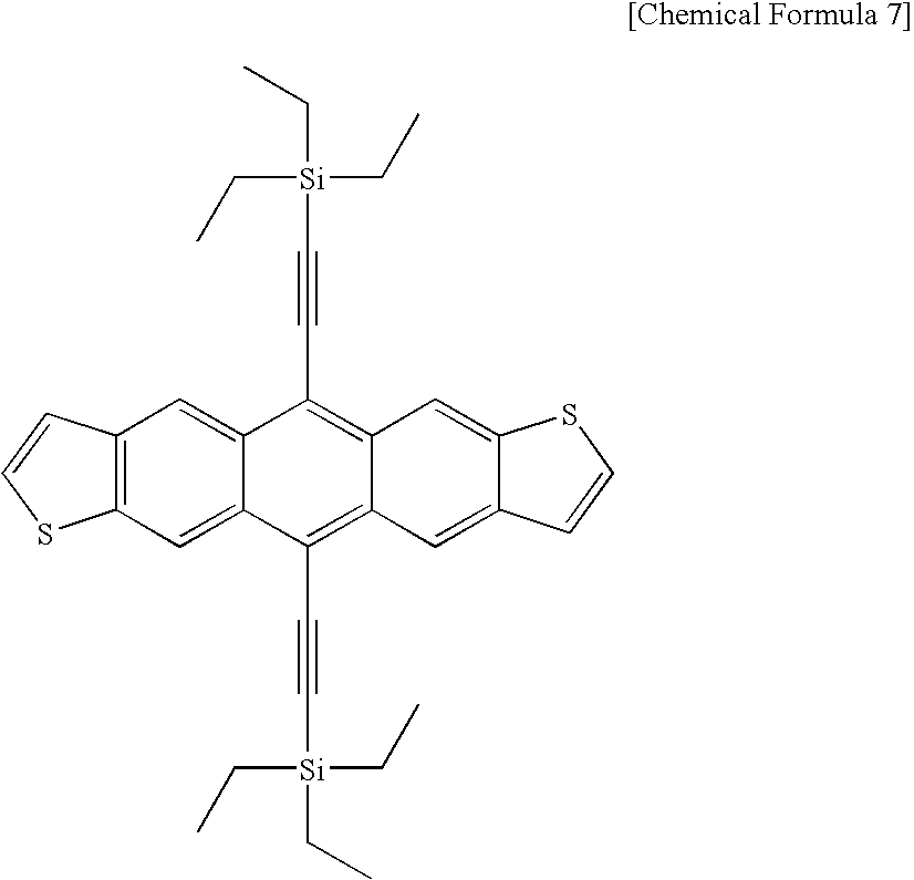
  • the organic semiconductor material that can be coated is typically represented by bis(triisopropylsilylethynyl) pentacene, bis(triethylsilylethynyl) anthradithiophene and poly-3-hexylthiophene.
  • the structural formula is given below:
  • the organic semiconductor material other than the above can be used if it can be dissolved in the organic solvent.
  • polyolefin based F8T2 or the thiophene based material disclosed in the Japanese Laid-Open Patent Publication No. 2004-186695 can be selected.
  • Toluene is a typical solvent used to prepare a semiconductor solution as a mixture of self-assembled monolayer material and organic semiconductor material. Chloroform, xylene, tetrahydronaphthalene, dichlorobenzene or trichlorobenzene can be selected as a solvent.
  • 3,4-dichlorobenzenethiol at a concentration of 0.005% by mass as a self-assembled monolayer material and bis(triisopropylsilylethynyl) pentacene at a concentration of 0.1% by mass as an organic semiconductor material are mixed and dissolved in toluene.
  • the semiconductor solution prepared by this procedure is coated between the source electrode 8 and the drain electrode 9 by the dispenser method, whereby a semiconductor layer 10 is formed.
  • the semiconductor layer 10 can be formed by the spin coating method, inkjet method or microcontact printing method in addition to the dispenser method. There is no restriction to the method of formation. Any method can be applied to the present invention if the organic semiconductor material together with solvent is coated and is then dried, whereby a semiconductor layer is formed.
  • Step S 7 wherein the self-assembled monolayer material in the semiconductor solution are yielded on the surfaces of the source electrode 8 and the drain electrode 9 after coating, in Step S 6 , the semiconductor solution prepared by mixing the self-assembled monolayer material with organic semiconductor material.
  • FIGS. 2 a , 2 b and 2 c are explanatory diagrams schematically showing how the self-assembled monolayer material is yielded on the surfaces of the source electrode 8 and the drain electrode 9 .
  • FIG. 2 a is a schematic diagram wherein the space between the source electrode 8 and the drain electrode 9 in the cross section given in FIG. 1 j is partially enlarged.
  • FIG. 2 b and FIG. 2 c are schematic diagrams wherein the portion between the source electrode 8 and the drain electrode 9 of the cross section of FIG. 1 m is partially enlarged.
  • FIG. 2 a shows that the semiconductor solution prepared by mixing the self-assembled monolayer material with organic semiconductor material in Step S 6 is dropped in the arrow-marked direction in the drawing.
  • the reference numeral 21 denotes a drop of the semiconductor solution to be dropped, and 20 a indicates the self-assembled monolayer material contained in the drop 21 of semiconductor solution.
  • FIG. 2 b shows that the drop 21 of the semiconductor solution having dropped spreads over the surfaces of the source electrode 8 and the drain electrode 9 through the action of the self-assembled monolayer material 20 a , whereby a semiconductor layer 10 is formed.
  • FIG. 2 c shows that the self-assembled monolayer material 20 a is deposited on the surfaces of the source electrode 8 and the drain electrode 9 to form a self-assembled monolayer 20 b , in Step S 7 .
  • the self-assembled monolayer material 20 a is yielded onto the electrode surface, there will be a reduction in contact resistance between the semiconductor portion of the semiconductor layer 10 and the electrode, whereby an organic TFT characteristics of a high degree of mobility and performance can be produced.
  • Step S 7 it is also possible to make such arrangements that the solvent of the semiconductor solution coated in Step S 6 by natural drying is evaporated and the self-assembled monolayer material in the semiconductor solution is yielded on the surfaces of the source electrode 8 and the drain electrode 9 , as shown in FIG. 2 c.
  • gas is blown on the substrate 1 so that the solvent of semiconductor solution is evaporated, and the self-assembled monolayer material 20 a is yielded on the surfaces of the source electrode 8 and the drain electrode 9 .
  • This allows the organic TFT on the substrate 1 to be dried under constant conditions, thereby reducing the variation in the characteristics of the manufactured organic TFT having been produced.
  • a gas heated to a predetermined temperature is blown on the substrate 1 heated to a predetermined temperature, and the self-assembled monolayer material 20 a is yielded on the surfaces of the source electrode 8 and the drain electrode 9 .
  • This allows the organic TFT on the substrate 1 to be dried in a shorter time. This procedure reduces the variation in the characteristics of the organic TFT having been produced.
  • Step S 7 gas to evaporate the solvent of the semiconductor layer 10 formed in Step S 6 .
  • FIGS. 3 a and 3 b are explanatory diagrams showing the process of drying the semiconductor layer 10 formed between the source electrode 8 and the drain electrode 9 explained with reference to FIGS. 1 k and 1 m .
  • the same reference numerals are assigned to the same components as those of FIGS. 1 k and 1 m , and the description is therefore omitted.
  • FIG. 3 a is a front view
  • FIG. 3 b is a cross section showing the cross sectional view of FIG. 3 a taken along arrow line X-X′.
  • the arrow mark L 1 of FIG. 3 a denotes the direction wherein the substrate 1 is conveyed.
  • the arrow mark D 1 of FIG. 3 b indicates the direction wherein gas is blown from an air blower 31 (not illustrated) in order to evaporate the solvent of the semiconductor layer 10 formed on the substrate 1 . Further, ⁇ 1 indicates the angle of blowing gas from the substrate 1 .
  • the gas blowing direction is not restricted to the example of FIG. 3 b .
  • Gas can be blown immediately from the top, or parallel to or perpendicular to the traveling direction of the substrate. However, gas is preferably blown in the same direction as the traveling direction of the substrate 1 , thereby drying the substrate.
  • the angle ⁇ 1 of the gas blown on the substrate 1 may be 90°.
  • gas may be blown on the substrate 1 immediately from the top.
  • Solvent can also be evaporated when this angle ⁇ 1 is 0 degree with respect to the substrate 1 , viz., when gas is blown parallel to the substrate.
  • the solvent can be evaporated in the shortest time.
  • the ⁇ 1 is preferably 45° or less, more preferably approximately 30°.
  • Nitrogen or rare gas is preferably used for drying. Further, gas temperature is from the room temperature to about 200° C. Gas temperature depends on the heat resistant temperature of the solvent and organic semiconductor material. It is lower when using the solvent of higher volatility, and is higher when using the solvent of higher boiling point and lower volatility.
  • Gas temperature must be lower than the temperature wherein the organic semiconductor material is decomposed. If there is no influence upon other members, the temperature may be higher than the softening point of the organic semiconductor material. There is no restriction to the shape of the gas nozzle.
  • the gas nozzle is preferably shaped to blow out gas in a linear shape.
  • the flow rate of gas per unit time is preferably 0.5 L/(min ⁇ mm 2 ) or more although it depends on the solvent to be evaporated.
  • the gas speed can be slower in the beginning, and can be increased with the progress of drying.
  • Gas can be blown in such a way that the member linearly blowing out gas moves parallel to the substrate 1 so that gas is blown all over.
  • the member for linear blowing of gas may be fixed in position, and the table holding the substrate may be moved. Both may be moved or fixed.
  • Step S 7 an insulating thin film and contact hole are formed.
  • a pixel electrode is formed by the coating type ITO, thereby completing production of the organic TFT.
  • the embodiment of the present invention allows stable formation of the self-assembled monolayer on the electrode surface in a shorter period of time, and hence provides a method of manufacturing an organic thin film transistor characterized by low costs and high performances, as well as the organic thin film transistor.
  • Example 1 only the conditions of the steps to be compared are changed, without the conditions for other steps being changed.
  • the test conditions in each step of Example 1 will be explained. After that, the steps under the same conditions will not be described to avoid duplication. Only the different conditions will be described.
  • Examples 1 through 7 a total of 25 organic TFT (5 by 5) were manufactured on the substrate 1 , and the effects were verified.
  • This TFT was manufactured in Steps S 1 through S 6 described with reference to FIGS. 1 a through 1 k and 1 m . Accordingly, steps will be numbered, and will be described in sequence. However, description of the common items will be omitted.
  • the substrate 1 used is the glass substrate having dimensions of 150 mm ⁇ 150 mm wherein the AlNd (alumineodymium) film as a thin conductive film 2 was formed on the surface to a thickness of 125 nm. A resist was formed on this substrate 1 to a thickness of approximately 1 ⁇ m, and exposure and development were carried out.
  • AlNd alumineodymium
  • S 4 A step of forming a SiO 2 film as a gate insulation layer 7 on the substrate 1 to a thickness of 500 nm according to the plasma CVD method using a TEOS (tetraethoxysilane) gas.
  • TEOS tetraethoxysilane
  • a positive resist thin film was formed on the gate insulation layer 7 to a thickness of approximately 1 ⁇ m, and exposure was conducted using a photomask having a pattern obtained by reversing the shapes of the source electrode 8 and the drain electrode 9 . Then development is carried out and the resist is removed from only the position wherein the source electrode 8 and the drain electrode 9 are to be provided. The resist is kept un-removed where these electrodes are not to be provided. An Au film is formed to a thickness of approximately 50 nm by sputtering, whereby the source electrode 8 and the drain electrode 9 are formed. The resist is then removed.
  • Self-assembled monolayer material 0.005% by mass of 3,4-dichlorobenzenethiol
  • Thickness of semiconductor material between the source electrode 8 and the drain electrode 9 after being dried 60 nm
  • Self-assembled monolayer material 0.005% by mass of pentafluorobenzenethiol
  • Thickness of semiconductor material after drying between the source electrode 8 and the drain electrode 9 60 nm
  • Self-assembled monolayer material 0.005% by mass of 1-hexadecanethiol
  • Thickness of the semiconductor material between source electrode 8 and drain electrode 9 after drying 60 nm
  • Self-assembled monolayer material 0.005% by mass of 3,4-dichlorobenzenethiol
  • Thickness of semiconductor material after drying between the source electrode 8 and the drain electrode 9 60 nm
  • Step S 6 the semiconductor solution of the following composition was used.
  • Self-assembled monolayer material 0.005% by mass of 3,4-dichlorobenzenethiol
  • Organic semiconductor material 0.1% by mass of poly-3-hexylthiophene
  • Thickness of semiconductor material after drying between the source electrode 8 and the drain electrode 9 60 nm
  • Step S 7 gas was blown on the substrate 1 so that the self-assembled monolayer material was deposited on the surfaces of the source electrode 8 and the drain electrode 9 .
  • Step S 6 Procedures up to the Step S 6 were performed under the same conditions as those of the Example 6.
  • Step S 7 gas temperature and table temperature are different from those of the Example 6.
  • a self-assembled monolayer was formed on the surfaces of the source electrode and drain electrode by the Step S 100 of immersing in the solution containing a self-assembled monolayer material and the Step S 101 of drying the solution containing a self-assembled monolayer material. After that, a semiconductor layer 10 was formed between the source electrode 8 and the drain electrode 9 , whereby an organic TFT was manufactured.
  • Step S 5 the same conditions as those of Example 1 were used for production, and therefore, the description will be omitted.
  • the following description starts from the Step S 100 for immersion in the solution containing the self-assembled monolayer material.
  • Self-assembled monolayer material 0.005% by mass of 3,4-dichlorobenzenethiol
  • Step S 101 The substrate 1 having been processed in the Step S 100 was dried in an oven having a temperature of 30° C. for five minutes.
  • Organic semiconductor material 0.1% by mass of bis(triethylsilylethynyl) anthradithiophene
  • Thickness between source electrode 8 and drain electrode 9 60 nm
  • Table 1 shows the test result. Twenty-five organic TFT elements on the glass substrate manufactured by various conditions under this test were evaluated to check the mobility and ON/OFF current ratio (current value between source and drain when the organic TFT is on/current value between source and drain when the organic TFT is off).
  • Example 1 Example 2
  • Example 3 Example 4
  • Example 5 Example 6
  • Example 7 Comp. 1 Mobility Average 0.014 0.013 0.01 0.011 0.012 0.031 0.045 0.004 (cm 2 /V ⁇ S) value
  • On/off Average 3.60E+04 3.20E+04 2.00E+04 1.90E+04 1.31E+04 6.99E+04 1.44E+05 1.40E+04 current value ratio
  • Example 7 Comparison between the Example 7 and Example 6 indicates that the organic TFT manufactured in the Example 7 had the mobility which was approximately 1.5 times as high as that manufactured in the Example 6, and the standard deviation/average value of mobility which was approximately 1/2. This shows that, when the substrate 1 and gas in Step S 7 are heated, an organic TFT characterized by still higher mobility and smaller variation can be obtained.
  • the present invention allows stable formation of the self-assembled monolayer on the electrode surface in a shorter period of time, and hence provides a method of manufacturing an organic thin film transistor characterized by low costs and high performances, as well as the organic thin film transistor.

Abstract

A method of manufacturing an organic thin film transistor characterized by low costs and high performances, the method in which the self-assemble monolayer is formed in a short period of time, and the organic thin film transistor are provided. A method of manufacturing an organic thin film a transistor having a gate electrode, a semiconductor layer, a source electrode, and a drain electrode on a substrate, wherein a semiconductor solution as a mixture of the self-assembled monolayer material and organic semiconductor material is coated between the source electrode and drain electrode, whereby a semiconductor layer is formed.

Description

This application is based on Japanese Patent Application No. 2006-14115 filed on May 22, 2006, in Japanese Patent Office, the entire content of which is hereby incorporated by reference.
TECHNICAL FIELD
The present invention relates to an organic thin film transistor manufacturing method and an organic thin film transistor.
BACKGROUND
With the spread of an information terminal, there has been a growing demand for a flat panel display as a computer display. Further, the information having been provided in the form of paper is now given in the form of electronic paper in ever-increasing occasions, as a result of progress in the information technology. There has been an increasing need for electronic paper or digital paper as a mobile display medium characterized by lightweight and excellent portability. Against this backdrop, development of a flat panel display apparatus has been carried out.
Generally in the flat panel display apparatus, a display medium is produced by using a device based on the technology of liquid crystal, organic electroluminescence and electrophoresis. To ensure uniformity of the screen brightness and screen rewriting speed, such a display medium is manufactured according to the technology based on an active drive element made of an organic thin film transistor (hereinafter referred to as “organic TFT”) as an image drive element.
In this case, in the production of the organic TFT element, a semiconductor thin film such as a-Si (amorphous silicon) and p-Si (polysilicon) and a thin metallic film such as a source, drain and gate electrode are sequentially formed on the glass substrate.
In the conventional practice, to form a bus line, electrode pattern and semiconductor layer on a substrate, patterning is carried out to form a circuit by the photolithographic technology (hereinafter referred to as “photolithography”). Photolithography is a technique wherein a photosensitive resist is coated on a thin film to be patterned, and the exposed thin film portion is dry- or wet-etched after exposure and development through a photo mask, whereby patterning is carried out. After patterning, the unwanted resist is stripped, and formation of films thereon is repeated to form a semiconductor layer.
As described above, the photolithography has been used to produce an organic TFT element. However, this involves a problem of complicated production process and requirements for large-scale facilities such as a clean room. In recent years, to make up for the disadvantage of the organic TFT element manufacturing process based on the conventional photolithographic process, there is a very active effort going on for research and development of the organic TFT element using an organic semiconductor material (Japanese Laid-Open Patent Publication H10-190001, Journal of Advanced Material, 2002, No. 2, P. 99 (Review)).
The organic TFT can be manufactured, for example, as follows, although it depends on the type of element structures: In the case of a bottom gate-bottom contact structure wherein the gate electrode is formed on the substrate, a gate electrode is formed on the substrate using the photolithography. After that, a gate insulation film is formed on the gate electrode by plasma CVD using a TEOS source, or the coated insulation material is formed by printing.
Then the source electrode and drain electrode are formed by photolithography. After that, an organic semiconductor layer is formed on the channel area between the source electrode and drain electrode.
The organic semiconductor layer is formed by vapor deposition under vacuum. The problem is that the organic TFT having been manufactured is expensive due to high costs of the production equipment. To solve this problem, the film is formed by coating the dispersion solution obtained by dispersing the organic semiconductor material in a solvent, or the solution obtained by dissolving the organic semiconductor material. Spin coating method or inkjet method is used for this coating. Further, micro-contact printing method is also being studied.
Generally, when an organic semiconductor layer is formed, it is important that the semiconductor layer should be formed so as to minimize the contact resistance between the organic semiconductor layer and source electrode or drain electrode, thereby obtaining an organic TFT characterized by a higher degree of mobility and smaller variation.
To solve the aforementioned problem, the following method is proposed. The self-assembled monolayer of the thiol compound is formed on the surfaces of a source electrode and drain electrode. After that, the semiconductor portion is formed on the channel portion, whereby the contact resistance is reduced (for example, see the Official Gazettes of U.S. Pat. No. 6,335,539 and U.S. Pat. No. 6,569,707).
However, to form the self-assembled monolayer of thiol compound on the surfaces of the source electrode and drain electrode according to the method disclosed in the Official Gazettes of U.S. Pat. No. 6,335,539 and U.S. Pat. No. 6,569,707, it is necessary to take a step of immersing the source electrode and drain electrode in the thiol-containing solution and a step of drying the thiol. This takes a lot of time. Further, it is difficult to set the conditions for the processes of immersing and drying. Variations occur to the TFT characteristics due to a slight difference in the conditions. Such problems have been kept unsolved.
SUMMARY
The object of the present invention is to solve the aforementioned problems and to provide a method of manufacturing a high-performance and low-cost organic thin film transistor, as well as the organic thin film transistor. In view of forgoing, one embodiment according to one aspect of the present invention is a method of manufacturing an organic thin film transistor which has a gate electrode, a gate insulation layer, a semiconductor layer; a source electrode and a drain electrode on a substrate, the method comprising the step of:
forming the semiconductor layer by applying to the source electrode, the drain electrode and therebetween a semiconductor solution into which a self-assembled monolayer material and an organic semiconductor material are mixed.
According to another aspect of the present invention, another embodiment is an organic thin film transistor, comprising:
a gate electrode;
a gate insulation layer which is formed on the gate electrode;
a source electrode which is formed on the gate insulation layer;
a drain electrode which is formed on the gate insulation layer; and
a semiconductor layer which is formed on the gate insulation layer by applying a semiconductor solution between the source electrode and the drain electrode, the semiconductor solution being a mixture of a self-assembled monolayer material and an organic semiconductor material.
According to another aspect of the present invention, another embodiment is a method of manufacturing an organic thin film transistor on an electrode formed on a substrate, the method comprising the steps of:
forming a semiconductor layer by applying to the electrode a semiconductor solution into which a self-assembled monolayer material, an organic semiconductor material and solvent are mixed; and
yielding the self-assembled monolayer material on the electrode by evaporating the solvent.
BRIEF DESCRIPTION OF THE DRAWINGS
FIGS. 1 a through 1 k and 1 m are explanatory diagrams representing the method of manufacturing the organic thin film transistor of the present invention;
FIGS. 2 a through 2 c are explanatory diagrams schematically showing how self-assembled monolayer material is deposited on the surfaces of a source electrode 8 and drain electrode 9; and
FIGS. 3 a and 3 b are explanatory diagrams showing the step of drying the semiconductor layer 10 formed between the source electrode 8 and the drain electrode 9.
DETAILED DESCRIPTION OF THE PREFERRED EMBODIMENT
The following describes the details of the present invention with reference to embodiment without the present invention being restricted thereto.
FIGS. 1 a through 1 k and 1 m are explanatory diagrams representing the method of manufacturing the organic thin film transistor of the present invention (hereinafter referred to as “TFT”). Referring to the FIGS. 1 a through 1 k and 1 m, the following sequentially describes the manufacturing method for forming a bottom gate type organic TFT provided with the source electrode 8 and the drain electrode 9, wherein a gate electrode 2 b is provided on the substrate 1 and a gate insulation layer 7 b and semiconductor layer 10 are further formed. The application of the present invention is not restricted to the bottom gate type. The present invention is applicable to any device configuration as exemplified by a top gate type, vertical type, and top-and-bottom type.
FIGS. 1 a, 1 c, 1 e, 1 g, 1 i and 1 k are plan views wherein the substrate 1 is viewed from the top. FIGS. 1 b, 1 d, 1 f, 1 h, 1 j and 1 m are cross sections taken along lines X-X′ of FIGS. 1 a, 1 c, 1 e, 1 g, 1 i and 1 k.
The following describes the Steps S1 through S7 to give an example of the method of manufacturing the organic P TFT of the present invention:
S1 . . . A step of forming the resist layer 4 of each electrode pattern on the substrate 1 wherein a thin conductive film 2 is formed.
S2 . . . A step of etching the substrate 1.
S3 . . . A step of removing the resist layer 4 on the gate electrode 2 b.
S4 . . . A step of forming the gate insulation layer 7.
S5 . . . A step of forming the source electrode 8 and the drain electrode 9
S6 . . . A step of forming the semiconductor layer 10 between the source electrode 8 and the drain electrode 9.
S7 . . . A step of yielding the self-assembled monolayer material in the semiconductor on the surfaces of the source electrode 8 and the drain electrode 9.
The following describes each of the steps:
S1 . . . A step of forming the resist layer 4 of each electrode pattern on the substrate 1 wherein a thin conductive film 2 is formed.
After a photosensitive resist is applied on the substrate 1 with the thin conductive film 2 formed thereon, exposure through the photomask of each electrode pattern and development are performed, thereby forming a resist layer 4 of each electrode pattern. In Step S1, the resist layer 4 b is formed on the substrate 1, as shown in FIGS. 1 a and 1 b.
In the present invention, there is no restriction to the substrate 1. For example, glass or flexible resin sheet can be employed. For example, using the vapor deposition, sputtering or CVD method, the thin conductive film 2 can be made of the material of low-resistant metal such as Al, Cr, Ta, Mo and Ag as a thin conductive film on the substrate 1 and the laminated structure of these metals, and the material doped with other materials may be used as the thin conductive film for the purpose of improving the heat-resistance of the metallic thin film and contact with the supporting substrate and avoiding a possible defect. A transparent electrode of ITO, IZO, SnO and ZnO can also be used.
S2 . . . A step of etching the substrate 1.
As shown in FIGS. 1 c and 1 d, the portion not covered by the resist layer 4 on the thin conductive film 2 is removed by etching the substrate 1.
S3 . . . A step of removing the resist layer 4 on the gate electrode 2 b.
As shown in FIGS. 1 e and 1 f, the resist layer 4 b on the gate electrode 2 b is removed.
S4 . . . A step of forming the gate insulation layer 7.
The gate insulation layer 7 is formed as shown in FIGS. 1 g and 1 h.
The gate insulation layer 7 is formed by a dry process of vapor deposition, sputtering, CVD method and atmospheric pressure plasma processing method. There is no restriction to materials for the gate insulation layer 7, and Various kinds of insulation films can be utilized. For example, the inorganic oxide coating of high relative dielectric constant such as silicon oxide, aluminum oxide, tantalum oxide and titanium oxide is employed.
Alternatively, an organic material such as a PVP, polyimide and polysiloxane type, and an inorganic membrane material can be used as a coating material.
S5 . . . A step of forming the source electrode 8 and the drain electrode 9.
A source electrode 8 and drain electrode 9 are formed as shown in FIGS. 1 n and 1 j.
In the present invention, in the process of forming the semiconductor layer 10 in Step S6, the semiconductor solution made up of mixture of the self-assembled monolayer material and organic semiconductor material is coated to form a semiconductor layer 10, whereby a self-assembled monolayer is formed on the surface of the source electrode 8 and the drain electrode 9. Accordingly, at least the surfaces of the source electrode 8 and the drain electrode 9 are preferably made of a material having a higher degree of affinity with the self-assembled monolayer material. Gold, platinum, tungsten, palladium, aluminum, chromium and titanium can be mentioned as materials having a higher degree of affinity with the self-assembled monolayer material. The self-assembled layer used in the present embodiment is yielded on the surfaces of the source electrode 8 and the drain electrode 9 so as to reduce the electric resistance between the electrode and semiconductor layer. Application of the material used in the present invention is not restricted to the self-assembled layer. Other material can be used if it is capable of reducing the electric resistance between the electrode and the semiconductor layer.
The source electrode 8 and drain electrode 9 are formed, for example, by sputtering these materials. In this case, the source electrode 8 and the drain electrode 9 need not be integrally formed by these materials. It is sufficient if at least the surfaces are made of these materials.
S6 . . . A step of forming the semiconductor layer 10 between the source electrode 8 and the drain electrode 9.
As shown in FIGS. 1 k and 1 m, a semiconductor layer 10 is formed so as to make electric connection with the source electrode 8 and the drain electrode 9 formed on the substrate 1, and to contact the gate insulation layer 7 b.
In the present invention, as described above, the semiconductor layer 10 is formed by coating the semiconductor solution of a mixture of the self-assembled monolayer material and organic semiconductor material.
As described in the structural formula of Formula 1, the self-assembled monolayer material applicable to the present invention is preferably the material containing a thiol group. R in Formula 1 indicates the aromatic compound containing the straight chain or branched chain alkyl, alkenyl, cycloalkyl or 6 through 25 carbon atoms.
R—SH  Formula 1
where R indicates the aromatic compound containing the straight chain or branched chain alkyl, alkenyl, cycloalkyl or 6 through 25 carbon atoms, and SH denotes a thiol group.
The self-assembled monolayer material containing the thiol group applicable to the present invention is typically represented by 3,4-dichlorobenzenethiol, pentafluoro benzenethiol, 1-hexadecanethiol. The structural formula of each material is shown below:
3,4-dichlorobenzenethiol
Figure US07670870-20100302-C00001
Pentafluoro benzenethiol
Figure US07670870-20100302-C00002
1-hexadecanethiol
Figure US07670870-20100302-C00003
4-nitrobenzenethiol, 2-mercaptobenzimidazole and 1-ocadecanethiol can be mentioned as a self-assembled monolayer material preferably applied to the present invention. The structural formula of the 4-nitrobenzenethiol and 2-mercaptobenzimidazole is given below:
4-nitrobenzenethiol
Figure US07670870-20100302-C00004
2-mercaptobenzimidazole
Figure US07670870-20100302-C00005
In addition to the thiol compound, a material capable of forming a self-assembled monolayer such as a silane coupling material can be used. The silane coupling material is preferably exemplified by octadesyl trichlorosilane and octyltrichlorosilane.
There is no restriction to the material of the organic semiconductor material as long as dissolution or dispersion in a solvent can be achieved. Taking the organic high molecular material for granted, pentacene which is a low molecular material can be dissolved in a heated solvent and can be coated, in recent years. The organic semiconductor material can be either a low- or high-molecular material.
The organic semiconductor material that can be coated is typically represented by bis(triisopropylsilylethynyl) pentacene, bis(triethylsilylethynyl) anthradithiophene and poly-3-hexylthiophene. The structural formula is given below:
Bis(triisopropylsilylethynyl) pentacene
Figure US07670870-20100302-C00006
Bis (triethylsilylethynyl) anthradithiophene
Figure US07670870-20100302-C00007
Poly-3-hexylthiophene
Figure US07670870-20100302-C00008
Even the organic semiconductor material other than the above can be used if it can be dissolved in the organic solvent. For example, polyolefin based F8T2 or the thiophene based material disclosed in the Japanese Laid-Open Patent Publication No. 2004-186695 can be selected.
Toluene is a typical solvent used to prepare a semiconductor solution as a mixture of self-assembled monolayer material and organic semiconductor material. Chloroform, xylene, tetrahydronaphthalene, dichlorobenzene or trichlorobenzene can be selected as a solvent.
For example, 3,4-dichlorobenzenethiol at a concentration of 0.005% by mass as a self-assembled monolayer material and bis(triisopropylsilylethynyl) pentacene at a concentration of 0.1% by mass as an organic semiconductor material are mixed and dissolved in toluene. The semiconductor solution prepared by this procedure is coated between the source electrode 8 and the drain electrode 9 by the dispenser method, whereby a semiconductor layer 10 is formed.
The semiconductor layer 10 can be formed by the spin coating method, inkjet method or microcontact printing method in addition to the dispenser method. There is no restriction to the method of formation. Any method can be applied to the present invention if the organic semiconductor material together with solvent is coated and is then dried, whereby a semiconductor layer is formed.
S7 . . . A step of yielding the self-assembled monolayer material in the semiconductor solution on the surfaces of the source electrode 8 and the drain electrode 9.
The following describes the Step S7 wherein the self-assembled monolayer material in the semiconductor solution are yielded on the surfaces of the source electrode 8 and the drain electrode 9 after coating, in Step S6, the semiconductor solution prepared by mixing the self-assembled monolayer material with organic semiconductor material.
FIGS. 2 a, 2 b and 2 c are explanatory diagrams schematically showing how the self-assembled monolayer material is yielded on the surfaces of the source electrode 8 and the drain electrode 9.
FIG. 2 a is a schematic diagram wherein the space between the source electrode 8 and the drain electrode 9 in the cross section given in FIG. 1 j is partially enlarged. Further, FIG. 2 b and FIG. 2 c are schematic diagrams wherein the portion between the source electrode 8 and the drain electrode 9 of the cross section of FIG. 1 m is partially enlarged.
FIG. 2 a shows that the semiconductor solution prepared by mixing the self-assembled monolayer material with organic semiconductor material in Step S6 is dropped in the arrow-marked direction in the drawing. The reference numeral 21 denotes a drop of the semiconductor solution to be dropped, and 20 a indicates the self-assembled monolayer material contained in the drop 21 of semiconductor solution.
FIG. 2 b shows that the drop 21 of the semiconductor solution having dropped spreads over the surfaces of the source electrode 8 and the drain electrode 9 through the action of the self-assembled monolayer material 20 a, whereby a semiconductor layer 10 is formed.
FIG. 2 c shows that the self-assembled monolayer material 20 a is deposited on the surfaces of the source electrode 8 and the drain electrode 9 to form a self-assembled monolayer 20 b, in Step S7. As described above, when the self-assembled monolayer material 20 a is yielded onto the electrode surface, there will be a reduction in contact resistance between the semiconductor portion of the semiconductor layer 10 and the electrode, whereby an organic TFT characteristics of a high degree of mobility and performance can be produced.
In Step S7, it is also possible to make such arrangements that the solvent of the semiconductor solution coated in Step S6 by natural drying is evaporated and the self-assembled monolayer material in the semiconductor solution is yielded on the surfaces of the source electrode 8 and the drain electrode 9, as shown in FIG. 2 c.
More preferably, gas is blown on the substrate 1 so that the solvent of semiconductor solution is evaporated, and the self-assembled monolayer material 20 a is yielded on the surfaces of the source electrode 8 and the drain electrode 9. This allows the organic TFT on the substrate 1 to be dried under constant conditions, thereby reducing the variation in the characteristics of the manufactured organic TFT having been produced.
Still more preferably, a gas heated to a predetermined temperature is blown on the substrate 1 heated to a predetermined temperature, and the self-assembled monolayer material 20 a is yielded on the surfaces of the source electrode 8 and the drain electrode 9. This allows the organic TFT on the substrate 1 to be dried in a shorter time. This procedure reduces the variation in the characteristics of the organic TFT having been produced.
Referring to FIGS. 3 a and 3 b, the following describes the method of blowing, in Step S7, gas to evaporate the solvent of the semiconductor layer 10 formed in Step S6.
FIGS. 3 a and 3 b are explanatory diagrams showing the process of drying the semiconductor layer 10 formed between the source electrode 8 and the drain electrode 9 explained with reference to FIGS. 1 k and 1 m. The same reference numerals are assigned to the same components as those of FIGS. 1 k and 1 m, and the description is therefore omitted. FIG. 3 a is a front view, and FIG. 3 b is a cross section showing the cross sectional view of FIG. 3 a taken along arrow line X-X′.
The arrow mark L1 of FIG. 3 a denotes the direction wherein the substrate 1 is conveyed.
The arrow mark D1 of FIG. 3 b indicates the direction wherein gas is blown from an air blower 31 (not illustrated) in order to evaporate the solvent of the semiconductor layer 10 formed on the substrate 1. Further, θ1 indicates the angle of blowing gas from the substrate 1.
The gas blowing direction is not restricted to the example of FIG. 3 b. Gas can be blown immediately from the top, or parallel to or perpendicular to the traveling direction of the substrate. However, gas is preferably blown in the same direction as the traveling direction of the substrate 1, thereby drying the substrate.
The angle θ1 of the gas blown on the substrate 1 may be 90°. To be more specific, gas may be blown on the substrate 1 immediately from the top. Solvent can also be evaporated when this angle θ1 is 0 degree with respect to the substrate 1, viz., when gas is blown parallel to the substrate. When the θ1 is approximately 30°, the solvent can be evaporated in the shortest time. The θ1 is preferably 45° or less, more preferably approximately 30°.
Nitrogen or rare gas is preferably used for drying. Further, gas temperature is from the room temperature to about 200° C. Gas temperature depends on the heat resistant temperature of the solvent and organic semiconductor material. It is lower when using the solvent of higher volatility, and is higher when using the solvent of higher boiling point and lower volatility.
Gas temperature must be lower than the temperature wherein the organic semiconductor material is decomposed. If there is no influence upon other members, the temperature may be higher than the softening point of the organic semiconductor material. There is no restriction to the shape of the gas nozzle. The gas nozzle is preferably shaped to blow out gas in a linear shape.
The flow rate of gas per unit time is preferably 0.5 L/(min·mm2) or more although it depends on the solvent to be evaporated. The gas speed can be slower in the beginning, and can be increased with the progress of drying.
Gas can be blown in such a way that the member linearly blowing out gas moves parallel to the substrate 1 so that gas is blown all over. The member for linear blowing of gas may be fixed in position, and the table holding the substrate may be moved. Both may be moved or fixed.
After Step S7, an insulating thin film and contact hole are formed. A pixel electrode is formed by the coating type ITO, thereby completing production of the organic TFT.
The embodiment of the present invention allows stable formation of the self-assembled monolayer on the electrode surface in a shorter period of time, and hence provides a method of manufacturing an organic thin film transistor characterized by low costs and high performances, as well as the organic thin film transistor.
EXAMPLE
The following describes the examples of the tests conducted to verify the effects of the present invention without the present invention being restricted thereto.
In Examples 1 through 7, only the conditions of the steps to be compared are changed, without the conditions for other steps being changed. The test conditions in each step of Example 1 will be explained. After that, the steps under the same conditions will not be described to avoid duplication. Only the different conditions will be described.
In Examples 1 through 7, a total of 25 organic TFT (5 by 5) were manufactured on the substrate 1, and the effects were verified.
Example 1
[Manufacturing the Organic TFT]
This TFT was manufactured in Steps S1 through S6 described with reference to FIGS. 1 a through 1 k and 1 m. Accordingly, steps will be numbered, and will be described in sequence. However, description of the common items will be omitted.
S1: The substrate 1 used is the glass substrate having dimensions of 150 mm×150 mm wherein the AlNd (alumineodymium) film as a thin conductive film 2 was formed on the surface to a thickness of 125 nm. A resist was formed on this substrate 1 to a thickness of approximately 1 μm, and exposure and development were carried out.
S2: A step of etching an ALNd film
S3: A step of removing a resist layer 4 from the gate electrode 2 b
S4: A step of forming a SiO2 film as a gate insulation layer 7 on the substrate 1 to a thickness of 500 nm according to the plasma CVD method using a TEOS (tetraethoxysilane) gas.
S5: After cleaning, a positive resist thin film was formed on the gate insulation layer 7 to a thickness of approximately 1 μm, and exposure was conducted using a photomask having a pattern obtained by reversing the shapes of the source electrode 8 and the drain electrode 9. Then development is carried out and the resist is removed from only the position wherein the source electrode 8 and the drain electrode 9 are to be provided. The resist is kept un-removed where these electrodes are not to be provided. An Au film is formed to a thickness of approximately 50 nm by sputtering, whereby the source electrode 8 and the drain electrode 9 are formed. The resist is then removed.
S6: An adequate quantity of the semiconductor solution of the following composition was dropped on the gate insulation layer 7 b between the source electrode 8 and the drain electrode 9 by the dispenser method.
Self-assembled monolayer material: 0.005% by mass of 3,4-dichlorobenzenethiol
    • Organic semiconductor material: 0.1% by mass of bis(triisopropylsilylethynyl) pentacene
    • Solvent: toluene
    • Channel: 1000 μm wide and 100 μm long
Thickness of semiconductor material between the source electrode 8 and the drain electrode 9 after being dried: 60 nm
S7: The self-assembled monolayer material 20 a was yielded on the surfaces of the source electrode 8 and the drain electrode 9 by natural drying method.
Example 2
The semiconductor solution of the following composition was used in Step S6.
S6: An adequate quantity of the semiconductor solution of the following composition was dropped on the gate insulation layer 7 b between the source electrode 8 and the drain electrode 9 by the dispenser method.
Self-assembled monolayer material: 0.005% by mass of pentafluorobenzenethiol
    • Organic semiconductor material: 0.1% by mass of bis(triisopropylsilylethynyl) pentacene
    • Solvent: toluene
    • Channel: 1000 μm wide, 100 μm long
Thickness of semiconductor material after drying between the source electrode 8 and the drain electrode 9: 60 nm
Example 3
The semiconductor solution of the following composition was used in Step S6.
S6: An adequate quantity of the semiconductor solution of the following composition was dropped on the gate insulation layer 7 b between the source electrode 8 and the drain electrode 9 according to the dispenser method.
Self-assembled monolayer material: 0.005% by mass of 1-hexadecanethiol
    • Organic semiconductor material: 0.1% by mass of bis(triisopropylsilylethynyl) pentacene
    • Solvent: toluene
    • Channel: 1000 μm wide, 100 μm long
Thickness of the semiconductor material between source electrode 8 and drain electrode 9 after drying: 60 nm
Example 4
The semiconductor solution of the following composition was used in Step S6.
S6: An adequate quantity of semiconductor solution of the following composition is dropped on the gate insulation layer 7 b between the source electrode 8 and the drain electrode 9 according to the dispenser method.
Self-assembled monolayer material: 0.005% by mass of 3,4-dichlorobenzenethiol
    • Organic semiconductor material: 0.1 by mass of bis(triethylsilylethynyl) anthradithiophene
    • Solvent: toluene
    • Channel: 1000 μm wide, 100 μm long
Thickness of semiconductor material after drying between the source electrode 8 and the drain electrode 9: 60 nm
Example 5
In Step S6, the semiconductor solution of the following composition was used.
S6: An adequate quantity of the semiconductor solution of the following composition was dropped on the gate insulation layer 7 b between the source electrode 8 and the drain electrode 9 according to the dispenser method.
Self-assembled monolayer material: 0.005% by mass of 3,4-dichlorobenzenethiol
Organic semiconductor material: 0.1% by mass of poly-3-hexylthiophene
Solvent: toluene
Channel: 1000 μm wide, 100 μm long
Thickness of semiconductor material after drying between the source electrode 8 and the drain electrode 9: 60 nm
Example 6
Procedures up to the Step S6 were performed under the same conditions as those of the Example 1. In Step S7, gas was blown on the substrate 1 so that the self-assembled monolayer material was deposited on the surfaces of the source electrode 8 and the drain electrode 9.
S7: The substrate 1 was placed on the drying table, and was dried by an air blower. The air blower is fixed and the table is moved, whereby air was blown all over and solvent was evaporated.
Gas blown from air blower 31: nitrogen gas
Gas flow rate: 2.0 L/(min.·mm2)
Gas temperature: 25° C.
Table temperature: 25° C.
Table traveling speed: approximately 2 m/min.
Direction of gas blow: L1 (shown in FIG. 3 a)
Gas blow angle θ1: 30°
Example 7
Procedures up to the Step S6 were performed under the same conditions as those of the Example 6. In Step S7, gas temperature and table temperature are different from those of the Example 6.
S7: A substrate 1 was placed on the drying table and was dried by an air blower. The air blower was fixed in position and the table was moved to blow air over the entire area, whereby solvent was evaporated.
Gas blow from air blower 31: nitrogen gas
Gas flow rate: 2.0 L/(min. ·mm2)
Gas temperature: 80° C.
Table temperature: 80° C.
Table traveling speed: approximately 2 m/min.
Direction of gas blow: L1 (shown in FIG. 3 a)
Gas blow angle θ1: 30°
Comparative Example 1
In Comparative Example 1, to verify the effects of the present invention, a self-assembled monolayer was formed on the surfaces of the source electrode and drain electrode by the Step S100 of immersing in the solution containing a self-assembled monolayer material and the Step S101 of drying the solution containing a self-assembled monolayer material. After that, a semiconductor layer 10 was formed between the source electrode 8 and the drain electrode 9, whereby an organic TFT was manufactured.
Up to Step S5, the same conditions as those of Example 1 were used for production, and therefore, the description will be omitted. The following description starts from the Step S100 for immersion in the solution containing the self-assembled monolayer material.
S100: The substrate 1 having completed the process up to S5 was immersed in the following solution.
Self-assembled monolayer material: 0.005% by mass of 3,4-dichlorobenzenethiol
Solvent: ethanol
S101: The substrate 1 having been processed in the Step S100 was dried in an oven having a temperature of 30° C. for five minutes.
S6: An adequate quantity of the semiconductor solution of the following compositions was dropped on the gate insulation layer 7 b between the source electrode 8 and the drain electrode 9 by the dispenser method.
Organic semiconductor material: 0.1% by mass of bis(triethylsilylethynyl) anthradithiophene
Solvent: toluene
Channel: 1000 μm wide, 100 μm long
Thickness between source electrode 8 and drain electrode 9: 60 nm
[Test Result]
Table 1 shows the test result. Twenty-five organic TFT elements on the glass substrate manufactured by various conditions under this test were evaluated to check the mobility and ON/OFF current ratio (current value between source and drain when the organic TFT is on/current value between source and drain when the organic TFT is off).
TABLE 1
Example 1 Example 2 Example 3 Example 4 Example 5 Example 6 Example 7 Comp. 1
Mobility Average 0.014 0.013 0.01 0.011 0.012 0.031 0.045 0.004
(cm2/V · S) value
Standard 0.004 0.0036 0.0036 0.0042 0.0033 0.0010 0.0007 0.0099
deviation
*1 0.2857 0.2792 0.3590 0.3800 0.2733 0.0324 0.0160 2.4850
On/off Average 3.60E+04 3.20E+04 2.00E+04 1.90E+04 1.31E+04 6.99E+04 1.44E+05 1.40E+04
current value
ratio Standard 11700 14700 9238 9186 8872 3446 4872 48371
deviation
*1 0.33 0.46 0.46 0.48 0.68 0.05 0.03 3.46
*1: Standard deviation/average value,
Comp.: Comparative example
All the organic TFTs manufactured in Examples 1 through 7 were superior to those produced in Comparative Example 1 in both the average value of mobility and the standard deviation/average value of mobility. This has verified that an organic TFT characterized by high mobility and smaller variations could be manufactured. Further, the organic TFTs manufactured in Examples 1 through 7 were characterized by a higher ON/OFF current ratio and smaller variation. These organic TFTs have been verified to have excellent performances.
In the organic TFT manufactured in the Examples 1 through 5 wherein tests were conducted by changing the compositions of the semiconductor solution, mobility was almost the same without a big difference. In the meantime, in the Example 6 wherein procedures up to Step S6 were carried out under the same conditions as those of Example 1 and gas was blown on the substrate 1 in Step S7, the organic TFT having been manufactured had the mobility which was approximately 2.2 times as high as that of Example 1, and standard deviation/average value of mobility which was as low as approximately 1/10. This has proved that, when gas is blown on the substrate 1 in Step S7, an organic TFT characterized by higher mobility and smaller variation can be produced.
Further, comparison between the Example 7 and Example 6 indicates that the organic TFT manufactured in the Example 7 had the mobility which was approximately 1.5 times as high as that manufactured in the Example 6, and the standard deviation/average value of mobility which was approximately 1/2. This shows that, when the substrate 1 and gas in Step S7 are heated, an organic TFT characterized by still higher mobility and smaller variation can be obtained.
As described above, the present invention allows stable formation of the self-assembled monolayer on the electrode surface in a shorter period of time, and hence provides a method of manufacturing an organic thin film transistor characterized by low costs and high performances, as well as the organic thin film transistor.

Claims (20)

1. A method of manufacturing an organic thin film transistor which has a gate electrode, a gate insulation layer, a semiconductor layer, a source electrode and a drain electrode on a substrate, the method comprising the step of:
forming the semiconductor layer by applying to the source electrode, the drain electrode and therebetween a semiconductor solution into which a self-assembled monolayer material and an organic semiconductor material are mixed.
2. The method of manufacturing an organic thin film transistor of claim 1, wherein the self-assembled monolayer material has a molecular structure represented by the following formula:

R—SH
wherein:
R is an aromatic compound containing a straight chain or branched chain alkyl, alkenyl, cycloalkyl or 6 through 25 carbon atoms;
SH is a thiol group.
3. The method of manufacturing an organic thin film transistor of claim 1, comprising the step of:
yielding the self-assembled monolayer material on the source electrode and the drain electrode after applying to the source electrode, the drain electrode and therebetween the semiconductor solution into which the self-assembled monolayer material and the organic semiconductor material are mixed.
4. The method of manufacturing an organic thin film transistor of claim 3, wherein the step of yielding the self-assembled monolayer material comprises the step of blowing a gas on a surface of the substrate on which the semiconductor solution has been applied.
5. The method of manufacturing an organic thin film transistor of claim 4, wherein the step of yielding the self-assembled monolayer material comprises the step of blowing a heated gas on a surface of a heated substrate on which the semiconductor solution has been applied.
6. An organic thin film transistor, comprising:
a gate electrode;
a gate insulation layer which is formed on the gate electrode;
a source electrode which is formed on the gate insulation layer;
a drain electrode which is formed on the gate insulation layer; and
a semiconductor layer which is formed on the gate insulation layer by applying a semiconductor solution between the source electrode and the drain electrode, the semiconductor solution being a mixture of a self-assembled monolayer material and an organic semiconductor material.
7. The organic thin film transistor of claim 6, surfaces of the source electrode and the drain electrode is formed of a material selected from the group consisting of gold, platinum, tungsten, palladium, aluminum, chrome and titanium.
8. The method of manufacturing an organic thin film transistor of claim 1, wherein the semiconductor solution contains a solvent, and the method comprises the step of yielding the self-assembled monolayer material on the source electrode and the drain electrode by evaporating the solvent.
9. The method of manufacturing an organic thin film transistor of claim 8, wherein the step of yielding the self-assembled monolayer material includes the step of evaporating the solvent by blowing a gas on the applied semiconductor solution.
10. The method of manufacturing an organic thin film transistor of claim 9, wherein the gas is blown at an angle of 30° from a surface of the substrate.
11. A method of manufacturing an organic thin film transistor on an electrode formed on a substrate, the method comprising the steps of:
forming a semiconductor layer by applying to the electrode a semiconductor solution into which a self-assembled monolayer material, an organic semiconductor material and solvent are mixed; and
yielding the self-assembled monolayer material on the electrode by evaporating the solvent.
12. The method of manufacturing an organic thin film transistor of claim 11, wherein the step of yielding the self-assembled monolayer material includes evaporating the solvent by blowing a gas on the applied semiconductor solution.
13. The method of manufacturing an organic thin film transistor of claim 12, wherein the gas is blown at an angle of 30° from a surface of the substrate.
14. The method of manufacturing an organic thin film transistor of claim 12, wherein the gas to be blown is a nitrogen gas or a rare gas.
15. The method of manufacturing an organic thin film transistor of claim 11, wherein the electrode to which the semiconductor solution is applied includes a source electrode and a drain electrode.
16. A method of manufacturing an organic thin film transistor which has a gate electrode, a gate insulation layer, a semiconductor layer, a source electrode and a drain electrode on a substrate, the method comprising the steps of:
forming the semiconductor layer by applying to the source electrode, the drain electrode and therebetween a semiconductor solution into which an organic semiconductor material, solvent and a material for decreasing an electric resistivity between the both electrodes and the semiconductor layer are mixed; and
yielding the self-assembled monolayer material on the source electrode and the drain electrode by evaporating the solvent.
17. The method of manufacturing an organic thin film transistor of claim 16, wherein the material for decreasing the electric resistivity includes a self-assembled monolayer material.
18. The method of manufacturing an organic thin film transistor of claim 16, wherein the step of yielding the self-assembled monolayer material includes the step of evaporating the solvent by blowing a gas on the applied semiconductor solution.
19. The method of manufacturing an organic thin film transistor of claim 18, wherein the gas is blown at an angle of 30° from a surface of the substrate.
20. The method of manufacturing an organic thin film transistor of claim 18, wherein the gas to be blown is a nitrogen gas or a rare gas.
US11/803,992 2006-05-22 2007-05-16 Method of manufacturing organic thin film transistor and organic thin film transistor Expired - Fee Related US7670870B2 (en)

Applications Claiming Priority (3)

Application Number Priority Date Filing Date Title
JP2006141155A JP2007311677A (en) 2006-05-22 2006-05-22 Organic thin film transistor and method for manufacturing the same
JP2006-141155 2006-05-22
JPJP2006-141155 2006-05-22

Publications (2)

Publication Number Publication Date
US20070267630A1 US20070267630A1 (en) 2007-11-22
US7670870B2 true US7670870B2 (en) 2010-03-02

Family

ID=38711198

Family Applications (1)

Application Number Title Priority Date Filing Date
US11/803,992 Expired - Fee Related US7670870B2 (en) 2006-05-22 2007-05-16 Method of manufacturing organic thin film transistor and organic thin film transistor

Country Status (2)

Country Link
US (1) US7670870B2 (en)
JP (1) JP2007311677A (en)

Cited By (2)

* Cited by examiner, † Cited by third party
Publication number Priority date Publication date Assignee Title
US10551745B2 (en) 2014-10-24 2020-02-04 Flexterra, Inc. Photopatternable compositions and methods of fabricating transistor devices using same
US10879477B2 (en) 2014-02-19 2020-12-29 Merck Patent Gmbh Cyclic amine surface modifier and organic electronic devices comprising such cyclic amine surface modifier

Families Citing this family (9)

* Cited by examiner, † Cited by third party
Publication number Priority date Publication date Assignee Title
KR100973300B1 (en) * 2008-02-26 2010-07-30 경희대학교 산학협력단 Organic thin film transistor and method of manufacturing the same
JP5022950B2 (en) * 2008-03-07 2012-09-12 株式会社日立製作所 Organic thin film transistor and manufacturing method thereof
WO2009151978A1 (en) * 2008-06-11 2009-12-17 3M Innovative Properties Company Mixed solvent systems for deposition of organic semiconductors
WO2010058662A1 (en) * 2008-11-19 2010-05-27 コニカミノルタホールディングス株式会社 Method for manufacturing organic thin film transistor, and organic thin film transistor
KR101510898B1 (en) 2008-11-21 2015-04-10 엘지디스플레이 주식회사 Organic thin film transitor
KR101958990B1 (en) 2012-05-04 2019-03-15 삼성전자주식회사 Organic thin film transistor and method of manufacturing the same
JPWO2019124506A1 (en) * 2017-12-22 2020-12-10 Jnc株式会社 Organic semiconductor ink mixed with materials that assist charge injection
US11398597B2 (en) * 2020-07-09 2022-07-26 Taiwan Semiconductor Manufacturing Company, Ltd. Transistor, semiconductor device including the same, and manufacturing method thereof
CN112062993B (en) * 2020-09-18 2022-07-01 中国科学院微电子研究所 Preparation method of monolayer semiconductor high polymer film

Citations (6)

* Cited by examiner, † Cited by third party
Publication number Priority date Publication date Assignee Title
JPH10190001A (en) 1996-12-20 1998-07-21 Lucent Technol Inc Manufacture of organic thin film transistor
US6335539B1 (en) 1999-11-05 2002-01-01 International Business Machines Corporation Method for improving performance of organic semiconductors in bottom electrode structure
US20070020798A1 (en) * 2005-07-22 2007-01-25 Xerox Corporation Methods to minimize contact resistance
US20070212807A1 (en) * 2006-03-07 2007-09-13 Jun Yamada Method for producing an organic thin film transistor and an organic thin film transistor produced by the method
US20090101892A1 (en) * 2002-11-25 2009-04-23 Dimitrakopoulos Christos D Organic underlayers that improve the performance of organic semiconductors
US20090159878A1 (en) * 2006-02-16 2009-06-25 Idemitsu Kosan Co., Ltd. Organic thin film transistor

Family Cites Families (6)

* Cited by examiner, † Cited by third party
Publication number Priority date Publication date Assignee Title
GB0130485D0 (en) * 2001-12-21 2002-02-06 Plastic Logic Ltd Self-aligned printing
JP4250444B2 (en) * 2002-04-01 2009-04-08 キヤノン株式会社 Manufacturing method of conductive member and conductive member
DE602004004519T2 (en) * 2003-04-16 2007-11-08 Matsushita Electric Industrial Co., Ltd., Kadoma EFFECT SOLUTION, METHOD FOR PRODUCING PATTERNS AND METHOD FOR PRODUCING AN ELECTRONIC DEVICE USING THIS SOLUTION, AND ELECTRONIC DEVICE
JP4550389B2 (en) * 2003-09-12 2010-09-22 株式会社日立製作所 Semiconductor device
US7115900B2 (en) * 2003-11-26 2006-10-03 Lucent Technologies Inc. Devices having patterned regions of polycrystalline organic semiconductors, and methods of making the same
JP4652704B2 (en) * 2004-03-11 2011-03-16 キヤノン株式会社 Organic semiconductor device

Patent Citations (7)

* Cited by examiner, † Cited by third party
Publication number Priority date Publication date Assignee Title
JPH10190001A (en) 1996-12-20 1998-07-21 Lucent Technol Inc Manufacture of organic thin film transistor
US6335539B1 (en) 1999-11-05 2002-01-01 International Business Machines Corporation Method for improving performance of organic semiconductors in bottom electrode structure
US6569707B2 (en) 1999-11-05 2003-05-27 International Business Machines Corporation Method for improving performance of organic semiconductors in bottom electrode structure
US20090101892A1 (en) * 2002-11-25 2009-04-23 Dimitrakopoulos Christos D Organic underlayers that improve the performance of organic semiconductors
US20070020798A1 (en) * 2005-07-22 2007-01-25 Xerox Corporation Methods to minimize contact resistance
US20090159878A1 (en) * 2006-02-16 2009-06-25 Idemitsu Kosan Co., Ltd. Organic thin film transistor
US20070212807A1 (en) * 2006-03-07 2007-09-13 Jun Yamada Method for producing an organic thin film transistor and an organic thin film transistor produced by the method

Non-Patent Citations (1)

* Cited by examiner, † Cited by third party
Title
Dimitrakopoulos, Christos D. And Malenfant, Patrick R.L., "Organic Thin Film Transistors for Large Area Electronics," Advanced Materials 2002, 14, No. 2, Jan. 16, (Review), Wiley-VCH Verlag GmbH, Weinheim, pp. 99-117.

Cited By (2)

* Cited by examiner, † Cited by third party
Publication number Priority date Publication date Assignee Title
US10879477B2 (en) 2014-02-19 2020-12-29 Merck Patent Gmbh Cyclic amine surface modifier and organic electronic devices comprising such cyclic amine surface modifier
US10551745B2 (en) 2014-10-24 2020-02-04 Flexterra, Inc. Photopatternable compositions and methods of fabricating transistor devices using same

Also Published As

Publication number Publication date
US20070267630A1 (en) 2007-11-22
JP2007311677A (en) 2007-11-29

Similar Documents

Publication Publication Date Title
US7670870B2 (en) Method of manufacturing organic thin film transistor and organic thin film transistor
TWI290734B (en) Electronic device, method of manufacturing an electronic device, and electronic apparatus
US8735871B2 (en) Organic thin film transistors
US7700403B2 (en) Manufacturing method of semiconductor device
US6844579B2 (en) Organic device including semiconducting layer aligned according to microgrooves of photoresist layer
Akkerman et al. TIPS-pentacene crystalline thin film growth
US20050287719A1 (en) Organic thin film transistor array panel and manufacturing method thereof
CN1716060A (en) Organic thin film transistor array panel and manufacture method thereof
WO2008093854A1 (en) Thin film semiconductor device fabrication method and thin film semiconductor device
CN1790727A (en) Organic thin film transistor for an OLED display
US7968871B2 (en) Organic thin film transistor
US9087999B2 (en) Method of fabricating an electronic device comprising allowing a self-assembled layer to form selectively
JP2007180462A (en) Electronic device, method of manufacturing same, and electronic equipment
US20070145371A1 (en) Thin-film transistor
US7754525B2 (en) Film formation method and manufacturing equipment for forming semiconductor layer
KR20140027391A (en) Method for the oriented crystallization of materials
US7776666B2 (en) Thin film transistor and method of manufacturing thin film transistor
CN101425563A (en) Preparation for anisotropic organic field effect transistor
US7829375B2 (en) Method for manufacturing organic thin film transistor and organic thin film transistor
WO2009098477A1 (en) Method of fabricating top gate organic semiconductor transistors
JP2004165257A (en) Organic thin film transistor element
JP2004273514A (en) Organic thin film transistor and its manufacturing method
JP2008300546A (en) Organic thin-film transistor
JP2008147465A (en) Manufacturing method of transistor, transistor, transistor circuit, electronic device, and electronic instrument
JP2008300419A (en) Organic thin-film transistor

Legal Events

Date Code Title Description
AS Assignment

Owner name: KONICA MINOLTA HOLDINGS, INC., JAPAN

Free format text: ASSIGNMENT OF ASSIGNORS INTEREST;ASSIGNORS:IZUMI, TOMOO;KOADA, MASAKAZU;REEL/FRAME:019389/0066

Effective date: 20070413

Owner name: KONICA MINOLTA HOLDINGS, INC.,JAPAN

Free format text: ASSIGNMENT OF ASSIGNORS INTEREST;ASSIGNORS:IZUMI, TOMOO;KOADA, MASAKAZU;REEL/FRAME:019389/0066

Effective date: 20070413

STCF Information on status: patent grant

Free format text: PATENTED CASE

FPAY Fee payment

Year of fee payment: 4

FPAY Fee payment

Year of fee payment: 8

AS Assignment

Owner name: MONUMENT PEAK VENTURES, LLC, TEXAS

Free format text: ASSIGNMENT OF ASSIGNORS INTEREST;ASSIGNOR:KONICA MINOLTA, INC.;REEL/FRAME:046530/0270

Effective date: 20180731

AS Assignment

Owner name: FLEX DISPLAY SOLUTIONS, LLC, TEXAS

Free format text: ASSIGNMENT OF ASSIGNORS INTEREST;ASSIGNOR:MONUMENT PEAK VENTURES, LLC;REEL/FRAME:052793/0554

Effective date: 20181024

FEPP Fee payment procedure

Free format text: MAINTENANCE FEE REMINDER MAILED (ORIGINAL EVENT CODE: REM.); ENTITY STATUS OF PATENT OWNER: LARGE ENTITY

LAPS Lapse for failure to pay maintenance fees

Free format text: PATENT EXPIRED FOR FAILURE TO PAY MAINTENANCE FEES (ORIGINAL EVENT CODE: EXP.); ENTITY STATUS OF PATENT OWNER: LARGE ENTITY

STCH Information on status: patent discontinuation

Free format text: PATENT EXPIRED DUE TO NONPAYMENT OF MAINTENANCE FEES UNDER 37 CFR 1.362

FP Lapsed due to failure to pay maintenance fee

Effective date: 20220302