US7669348B2 - Apparatus, method and system for treating sewage sludge - Google Patents
Apparatus, method and system for treating sewage sludge Download PDFInfo
- Publication number
- US7669348B2 US7669348B2 US11/539,903 US53990306A US7669348B2 US 7669348 B2 US7669348 B2 US 7669348B2 US 53990306 A US53990306 A US 53990306A US 7669348 B2 US7669348 B2 US 7669348B2
- Authority
- US
- United States
- Prior art keywords
- drum
- sludge
- discharge
- plates
- moisture
- Prior art date
- Legal status (The legal status is an assumption and is not a legal conclusion. Google has not performed a legal analysis and makes no representation as to the accuracy of the status listed.)
- Active, expires
Links
Images


Classifications
-
- F—MECHANICAL ENGINEERING; LIGHTING; HEATING; WEAPONS; BLASTING
- F26—DRYING
- F26B—DRYING SOLID MATERIALS OR OBJECTS BY REMOVING LIQUID THEREFROM
- F26B11/00—Machines or apparatus for drying solid materials or objects with movement which is non-progressive
- F26B11/12—Machines or apparatus for drying solid materials or objects with movement which is non-progressive in stationary drums or other mainly-closed receptacles with moving stirring devices
- F26B11/16—Machines or apparatus for drying solid materials or objects with movement which is non-progressive in stationary drums or other mainly-closed receptacles with moving stirring devices the stirring device moving in a vertical or steeply-inclined plane
-
- F—MECHANICAL ENGINEERING; LIGHTING; HEATING; WEAPONS; BLASTING
- F26—DRYING
- F26B—DRYING SOLID MATERIALS OR OBJECTS BY REMOVING LIQUID THEREFROM
- F26B25/00—Details of general application not covered by group F26B21/00 or F26B23/00
- F26B25/22—Controlling the drying process in dependence on liquid content of solid materials or objects
- F26B25/225—Controlling the drying process in dependence on liquid content of solid materials or objects by repeated or continuous weighing of the material or a sample thereof
-
- F—MECHANICAL ENGINEERING; LIGHTING; HEATING; WEAPONS; BLASTING
- F26—DRYING
- F26B—DRYING SOLID MATERIALS OR OBJECTS BY REMOVING LIQUID THEREFROM
- F26B2200/00—Drying processes and machines for solid materials characterised by the specific requirements of the drying good
- F26B2200/18—Sludges, e.g. sewage, waste, industrial processes, cooling towers
Definitions
- the goal of treating sewage sludge is to neutralize pathogens to an environmentally safe level and to reduce vector attractiveness; i.e., to make the sewage sludge unattractive to rats, mice, flies, etc.
- drying apparatus of various forms have been used to stabilize sewage sludge and produce a granular end product that appeared to be satisfactory, but was so extremely dry, for example in excess of 90% dry solids, such that the end product was often dusty and difficult to handle. because such processes and equipment lacked the ability to determine the solids concentration with a degree of precision, in that they simply evaporated water until the product became very dry.
- the efficiency of such an operation is in large part a function of the heated surface area that comes into contact with the material that is being processed, the result is that as the volume of material in the batch processing container is being reduced, the surface area that is in contact with the material being processed is likewise reduced, causing a corresponding reduction in the rate of evaporation of the liquid, principally water, that is a component of the sludge that is being processed.
- the present invention provides an apparatus, process and system for thermal stabilization of sewage sludge, with moisture reduction to produce an end product having a solids concentration that is predetermined, generally between 10% and 99% solids, with the option of lime treatment or treatment by other chemical additives.
- an object of this invention to provide an apparatus, process and system for treating sewage sludge by drying and/or other chemical treatment, such as lime addition or the like, in which the sludge is delivered into a treatment container where it is mixed or tumbled while heat is applied to the material being treated, and wherein moisture gases principally water, is, drawn off and evaporated, with the treated material then being discharged from the container, and wherein one or more weight-responsive members are used to determine the solids content of the material being treated, at any given time, by measuring the difference in weight of material in the container before and after moisture is drawn off from the material.
- chemical treatment such as lime addition or the like
- weight-responsive member(s) include one or more load cells that support the container.
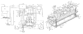
- FIG. 1 is an overall schematic view of an apparatus and process for practicing this invention, in which a container or drum D is shown for receiving dewatered sludge or cake from a conveyor or pump unit P that in turn, receives sewage sludge from a sludge storage silo SS, and wherein heated fluid HF is provided to the drum D, with moisture being drawn off from the drum for delivery to a scrubber condenser SC.
- Lime L may be provided from a lime storage silo or other chemicals CH added for delivery to the drum D.
- Various controls aid control lines are operated via a programmed computer C, such that the treated sludge is discharged from the drum D to a discharge conveyor DC from which the processed sludge is discharged, at a predetermined desired solids content.
- the processed sludge is conveyed to storage by a conveyor which may be used to cool the product before the finished product is stored in a pile or in a bulk silo.
- FIG. 2 is a partial schematic view of the driver unit D illustrated in FIG. 1 with a portion of the casing fragmentally broken away, to illustrate the internal components of the drum D.
- FIG. 2A is an enlarged detail view of one of the openable discharge units for discharged treated product from the drum D.
- FIG. 2B is a fragmentary transverse view of a portion of one of the rotatable disks from inside the drum D taken along the line 2 B- 2 B of FIG. 2 .
- FIG. 2C is an illustration similar to that of FIG. 2B , but wherein one of the rotatable disks are shown having an alternative configuration to the configuration of the rotatable disk illustrated in FIG. 2B .
- FIG. 3 is an enlarged illustration of the drum D to that illustrated in FIGS. 1 and 2 , and wherein a portion of the casing of the drum is shown broken away, for clarity of illustration of the means for providing heated fluid to rotatable disks inside the drum, and between internal and external walls of the drum D, with the discharge units for discharging treated sludge from the bottom of the drum D, being more clearly illustrated.
- FIG. 4 is an enlarged perspective view of the drum D with the casing being shown broken away, to better illustrate the rotatable shaft and disks within the drum, and with delivery ducts for delivering sludge to be treated into the drum D also being illustrated, and with a discharge conveyor DC also being, illustrated beneath the drum D, for receiving treated sludge therefrom, and with the drum and its frame being illustrated, supported on load cells for weight measurement.
- FIG. 4A is an enlarged detail view of a cross-section to the casing for the drum, showing a channel for heated fluid therein in enlarged cross-section.
- FIG. 4B is an illustration of a discharge gate for discharging processed sludge from the drum D, at the bottom thereof but wherein the control for operating the discharge gate of FIG. 4B is an alternative embodiment to that of FIGS. 1 , 2 and 3 , being comprised of a manual control apparatus.
- FIG. 4C is an enlarged fragmentary, longitudinal sectional view taken through the left end of the treated sludge take-off conveyor, with the illustration of FIG. 4C being taken generally along the line 4 C- 4 C of FIG. 4 .
- FIG. 1 wherein there is illustrated the drum 20 , also identified by the letter “D” which functions as an evaporator of liquids, essentially water in the form of moisture.
- the untreated sewage sludge is delivered via a from the sludge storage silo 21 with conveyors or a pump, also identified as “SS” in FIG. 1 , having a conveyor generally designated by the numeral 22 at the bottom thereof, for delivering the untreated sewage sludge into a further cylindrical dewatering conveyor generally designated by the numeral 23 , having an auger 24 therein for discharging the sewage sludge via a discharge gate 25 , in the direction of the arrow 26 therefrom, into a cake pump apparatus 27 , also indicated by the letter “P”, from which it is pumped via delivery line 28 and its sub-delivery lines 30 , 31 and 32 , through respective controlled valves 33 , 34 and 35 , and then through entry openings 36 , 37 and 38 , into the drum 20 , via respective delivery lines 40 , 41 and 42 .
- SS conveyors or a pump
- the drum 20 is generally cylindrical and is horizontally situated as shown in FIG. 1 , to have a horizontally disposed rotatable shaft 43 extending from the right end 44 thereof.
- the shaft 43 extends through the drum 44 , and outwardly of the left end 45 thereof, driven via a drive pulley 46 , that, in turn, is driven by a motor 47 , as shown.
- Heated fluid is provided via a thermal fluid heater 50 , delivering the heated fluid via line 51 to the interior of the rotatable shaft 43 , as will be further described hereinafter.
- the heated fluid preferably oil, will provide heat within the drum 20 , for heating the sewage sludge that is disposed therein for the driving off of moisture, generally water, therefrom, as the moisture evaporates from the sewage sludge.
- moisture thus leaves the drum 20 via line 52 , to be delivered to a scrubber/condenser 53 , also identified as “SC” in FIG. 1 .
- the rate of withdrawal of the air may be varied to optimize moisture removal without excessive loss of heat.
- lime in some form may be provided from a lime storage silo also identified as “L” in FIG. 1 , which periodically may have lime delivered thereto via line 55 from a lime delivery truck, or the like.
- the lime may be delivered from the storage silo 54 , through the bottom thereof, via a discharge auger 56 , having a plurality of discharge gates 57 , 58 and 60 at the bottom thereof, for discharging lime via lines 61 , 62 and 63 respectively into the drum 20 via drum inlets 36 , 37 and 38 , respectively.
- chemical hopper 64 also identified as “CH” in FIG. 1
- line 65 may be provided from chemical hopper 64 , to be discharged therefrom via line 65 , into the drum 10 via line 28 , or in any other delivery manner, preferably to enter the drum 20 via inlets 36 , 37 and 38 .
- the entire operation can be controlled from a programmed computer 66 , also identified in FIG. 1 as “C”.
- the computer 66 can control the operation of the sewage sludge discharge conveyor 23 via control line 70 , the opening of sewage sludge delivery gates 25 via line 71 , the operation of the cake pump 27 via control line 72 , the operation of sewage sludge delivery valves 33 , 34 and 35 , the operation of valve control lines 73 , 74 and 75 , for sludge delivery valves 33 , 34 , 35 , respectively, as well as many other functions that will hereinafter be described.
- the control of the amount and temperature of thermal fluid delivered via thermal fluid heater 50 , via line 51 , to the drum 20 can likewise he controlled by the computer 66 , via control line 76 .
- the optional delivery of lime via the lime storage silo 54 when it is desired to increase the pH of the sewage sludge, for vector control or the like, to the drum 20 can be controlled from the programmed computer 66 via gate control lines 77 , 78 and 80 , which respectively control the gates 60 , 58 and 57 for discharge of lime from conveyor 56 into the respective inlets 36 , 37 and 38 of drum 20 , as shown in FIG. 1 .
- sewage sludge chemicals can be delivered from hopper 64 via line 65 and delivery line 28 by opening or closing a control valve 81 , that, in turn, is controlled via line 82 , also connected to the programmed computer 66 .
- the controlled discharge gates 84 , 85 , 86 , 87 and 88 allow for discharge of the treated sludge into a discharge conveyor 103 , also identified by the letters “DC” in FIG. 1 . Then, the discharge from the discharge conveyor can pass via line 104 into a further storage silo truck or the like 105 either immediately or after being handled by intermediate conveyor devices (not shown), as shown in FIG. 1 .
- the treatment drum 20 is mounted on horizontal and vertical frame members 106 , 107 , 108 , 110 and 111 , as shown in FIGS. 1 and 4 .
- the horizontal frame members are supported by four vertical frame members, such as those 107 and 108 , with two mounted on each side, (front and back) of the horizontal frame members, which carry the drum 20 .
- the vertical frame members 107 and 108 and their corresponding vertical frame members (not shown) at the rear of the drum 20 as shown in FIG. 1 are each mounted on weight-responsive members in the form of load cells 112 and 113 , that, in turn, may be mounted on a floor, or, as shown in FIG. 4 , may be mounted on other floor-mounted horizontal supports 114 , 115 , and 116 .
- the load cells 112 and 113 are electrically connected via control lines 117 and 118 , together, and to the programmed computer 66 , via control line 120 .
- the load cells may, if desired be constructed in accordance with one or more of U.S. Pat. Nos. 5,770,823; 4,064,744; 4,166,997, 4,454,770, and 5,313,022 the complete disclosures of which are herein incorporated by reference.
- chemicals may be added from the hopper 64 as shown in FIG. 1 , via feed tine 69 , to the sludge feed line 28 , in the direction of the arrow 122 , to pass through valves 33 , 34 , and 35 via sub-feed lines 30 , 31 , and 32 respectively to enter the drum 20 via inlet openings 36 , 37 and 38 from feed lines 40 , 41 and 42 , as permitted by the programmed computer 66 which controls the valves 33 , 34 , and 35 via control lines 73 , 74 and 75 as shown in FIG. 1 .
- a hot oil return line 123 for returning hot oil from the drum 20 hack to the thermal fluid heater 50 , through a pump 124 thereof
- the rotatable shaft 43 disposed within the drum 20 carries generally plate-like cylindrical disks 125 mounted thereon, with the disks 125 being generally cylindrical, each having its outer periphery 126 spaced radially inwardly as shown at 127 in FIG. 3 , from the inner cylindrical wall 128 of the drum 20 , such spacing 127 preferably being approximately 3 inches or the like to allow for free flow of sludge material and any other ingredients entering into the drum 20 via inlets 36 , 37 and 38 , axially throughout the drum 20 between the ends 44 , 45 of the drum, across the clearance spaces 127 radially outwardly of the disks 125 .
- two or more rotating shafts with disks can be used to increase the capacity of the device.
- the rotatable shaft 43 has mounted thereon a plurality of preferably planar plates 130 , shown in phantom in FIG. 2 .
- the plates 130 are adapted to rotate with the shaft 43 , and each have an outermost edge 131 that is in close, but slightly spaced relation to the inner cylindrical wall 128 of the drum 120 , for scraping sludge that is being treated from the inner cylindrical wall 128 , to avoid sludge build-up thereon.
- the plates 130 thereby operate as a pusher means, for pushing material being treated, in a circular direction as the shaft 43 rotates.
- an alterative configuration for the shaft-mounted plates are provided each in the form of a segment of a disk 132 , having a notch-out 133 therein, with the disk 132 being otherwise similarly constructed to the construction of the disk 125 of FIG. 2B .
- the notch-out 133 allows for additional possibilities for axial flow of material being processed throughout the drum 20 , in addition to the axial flow permitted by material passing axially throughout the drum 20 via the radial spaces 127 between the peripheries 126 of the disks 125 inward of the cylindrical inner wall 128 of the drum 20 .
- rods 133 carried between and by the disks 125 , for rotation therewith, as the disks 125 rotate in the direction of the arrows 126 shown therein, to additionally act as a pusher means for pushing, sludge material with or without other ingredients, and tumbling or mixing the same within the drum 20 .
- an exhaust duct 134 for carrying off gases in the form of moisture, with or without dust or the like, via representative discharge lines 135 , illustrated, to represent moisture being drawn off from liquid, principally water being evaporated from sludge being processed within the drum 20 .
- the moisture that is drawn off is provided via line 52 , to the scrubber/condenser 53 , illustrated in FIG. 1 .
- the rate of removal may be varied to maximize the removal of moisture while minimizing the loss of heat or BTUs.
- the discharge or take-off conveyor 103 Mounted beneath the drum 20 the discharge or take-off conveyor 103 , extending axially therealong, as shown in FIG. 4 , has openings at its upper end (not shown) for receipt of dried sludge being discharged from the drum 20 through controlled discharge gates 84 , 85 , 86 , 87 and 88 as shown in FIG. 3 , through openings in the top 140 of the discharge conveyor 103 .
- Inside the discharge conveyor is a generally helically disposed auger shaft-mounted as shown at the left end of FIG. 4 , for axial conveyance of treated sludge therealong, to be discharged therefrom, as shown via discharge line 104 as described above with respect to FIG. 1 .
- an enlarged cross-sectional detail of the cylindrical wall of the drum 20 is shown as including an inner wall 142 and an outer wall 143 spaced therefrom, defining a generally cylindrical space 144 therebetween.
- a layer of insulation 145 may be provided at, or as part of the outer wall 143 , to preserve heat within the drum 20 .
- heated fluid preferably oil provided from the thermal fluid heater 50 is provided via line 51 , between hollow end wall portions 146 and 147 , to enter into the cylindrical zone 144 described above, in the direction of the arrow 148 .
- heated oil passes through the rotating shaft 150 to enter into the interiors 151 of the disks, to heat the exterior surfaces of the disks which will then engage sludge that is being processed therein, to transfer heat to the sludge, for evaporation of moisture therefrom, drying the sludge, with the moisture then passing out through the exhaust port 134 of the drum 20 , and to the scrubber/condenser 53 , via line 52 , as described above.
- FIG. 4B there is shown an alternative embodiment for the gates 84 , 85 , 86 , 87 and 88 of FIG. 3 , in the form of a discharge gate 154 having a solenoid or other control 155 , which is operated by a hand crank 156 or the like, for manually opening the gates 154 , instead of the manner described above with respect to the gates of FIGS. 1-3 , which are controlled by the programmed computer 66 .
- a plurality of temperature sensors 160 may be present in the drum 20 for sensing the temperature at various locations therein, as the sewage sludge is being mixed or tumbled, and delivering that information via control line 161 to the computer 66 , for determining if the desired temperature, for example 72° C. is reached for a desired period of time, for example at least 20 minutes, for providing information about the rate of evaporation of moisture, generally water from the sewage sludge being treated.
- a cooling means is provided for the take-off conveyor 140 , for cooling treated sludge in the take-off conveyor 140 .
- the cooling means can be of any type, but may, for example, be in the form of a continuous, spiral wound tubing 164 , between outer and inner walls 165 , 166 of the take-off conveyor 140 , with suitable water feed and discharge lines 167 and 168 , respectively, for cooling the treated sewage sludge that has been discharged from the drum 20 , as it is passed through the take-off conveyor 140 by means of the shaft-mounted helical auger.
- the sewage sludge that is stored in the silo 21 is withdrawn therefrom by means of the generally hellical conveyor 22 at the bottom thereof, and enters into a preferably dewatering conveyor 23 , also preferably having a generally helical auger therein, for discharging sewage sludge therefrom, via the discharge gate 25 , with the sludge then being delivered via line 26 to the cake pump apparatus 27 , from which it is pumped via line 28 and its sub-delivery lines 30 , 31 and 32 through valves 33 , 34 and 35 that are operated by the computer 66 , to deliver the sewage sludge into the drum 20 , through entry openings 36 , 37 and 38 .
- lime treatment can be provided from a storage bin 54 that has been supplied from a truck or the like via line 55 with the lime then being discharged via an auger type conveyor 56 , through gates 57 , 58 and 60 , to be provided into the drum via lines 61 , 62 and 63 .
- sludge intake line 28 can be provided from a chemical hopper 64 via line 65 into sludge intake line 28 , or, alternatively, directly into the drum 20 (not shown).
- a heat medium preferably heated oil
- a thermal fluid heater 50 via line 51 into the center of the shaft 43 of the drum 20 , with the heated oil heating the hollow center of the shaft 51 within the drum 20 , as well as heating the interiors 151 of the disks 125 , in order to maximize the surface area of the heated portions of the drum 20 , to maximize the opportunity for sewage sludge containing either no additional materials, or containing lime or other chemicals, for maximum contact with heated surfaces, to facilitate and maximize the evaporation of moisture therefrom.
- a thermal fluid heater 50 via line 51 into the center of the shaft 43 of the drum 20 , with the heated oil heating the hollow center of the shaft 51 within the drum 20 , as well as heating the interiors 151 of the disks 125 , in order to maximize the surface area of the heated portions of the drum 20 , to maximize the opportunity for sewage sludge containing either no additional materials, or containing lime or other chemicals, for maximum contact with heated surfaces, to facilitate and maximize the evaporation of moisture therefrom.
- pusher means in the form of the plates 130 described above and/or the rods 133 facilitate tumbling and pushing and otherwise mixing the sewage sludge within the drum 20 .
- the generally radially disposed plates 130 facilitate the prevention of accumulation of sewage sludge on the inner surface of the cylindrical wail 128 of the drum, because such run in close clearance to the inner surface 128 .
- One or more sensors 160 can sense the temperature of sewage sludge within the drum 20 and communicate the same via line 161 , back to the computer 66 to signal to the computer the temperature of the sludge at any given time, or when the sludge temperature has reached a desired predetermined level.
- the drum 20 is mounted on a plurality of weight-responsive members 112 , 113 (preferably comprising four such members), which weight-responsive members are preferably load cells.
- the load cells communicate the weight of the drum and its framing structure, including the weight of sludge entering the drum before and after water is removed, and in fact such load cells communicate changes in weight on a continuous basis back to the computer 66 .
- the computer 66 signals the opening of discharge gates 84 , 85 , 86 , 87 and 88 for the discharge of treated sludge from the drum 20 , into the take-off conveyor 103 , through the top 140 thereof, wherein the dried sludge is delivered through the cooled discharge conveyor which can be cooled in the manner set forth in FIG. 4C , with the helical screw auger 141 delivering the dried and treated sludge material from the left-most end of the discharge conveyor 103 , as shown at 104 , into a storage silo or the like, or even a truck for carrying the same away, as shown at 105 .
- the process described herein effectively stabilizes sewage sludge by greatly reducing disease carrying pathogens and minimizes the potential for transmission of pathogens by reducing the potential for vectors to be attracted to the finished product.
- the end product can be further conditioned to reduce the moisture content, in effect reducing the volume of product that needs to be transported and disposed.
- the process environment is essentially sealed to minimize undesirable emissions.
- the end product is thereby conditioned to further reduce emissions and dusting, and is a product of relatively uniform size and consistency.
- the cooling of the end product in the take-away conveyor 103 serves to minimize the release of both steam and ammonia and also results in a hardening of the finished product that enhances its friability and enables the sizing of the product to produce a product with nominal or no odors, of uniform size, and having a granular consistency.
- load cells or other weight-responsive members provides a means to measure weight gravimetrically, to monitor the weight of the contents of the drum so that through simple mathematical calculations, preferably performed by the computer a predetermined solids concentration of the contents of the drum can be accurately and repeatedly produced.
- the process can be practiced either in a batch operation, a pulsed operation, or in a continuous operation.
- the computer will control the delivery of sludge to be processed into the drum, and after a predetermined time, or when the heat sensors in the drum signal the computer to having reached a predetermined heat level, the gates at the bottom of the drum will be opened automatically as dictated by the computer, to discharge treated sludge to the take-away conveyor.
- the system can be operated such that a predetermined amount of material is added to the drum and, subsequently, as the initial material is reduced in weight through evaporation, as noted by the load cells or other weight-responsive means, the computer can signal the opening of appropriate valves for introduction of additional material into the drum.
- a rate of evaporation is established, enabling the computer to set a feed rate and operate the inlet valves that supply sewage sludge to the drum at a continuous rate.
- a system tot thermal stabilization of sewage sludge followed by additional moisture reduction that produces a predetermined end product concentration that can be between 10% and 99% solids.
- the system delivers a sludge cake to the drum, in which sewage sludge is thermally processed, with optional chemical treatment by lime or other chemicals.
- the resultant dried product having a solids concentration that can be predetermined to be between 10% and 99% dry, is thereby produced.
- the gas scrubbing can eliminate or at least very substantially reduce noxious odors.
- the system described herein stabilizes sludge in a virtually sealed environment, which helps to control offensive odors, withdrawn gasses and particulates while allowing the operator the flexibility to produce a friable end product that is more preferably between 50% and 99% dry solids.
- the system can also be manually operated, as described above.
- the sewage sludge will be retained within the drum or thermal reactor for a period of time, adding heat until the final product's solids concentration reaches the predetermined desired concentration.
- an apparatus, process and system for stabilizing sewage sludge, wherein an inventory of sludge is accumulated at some known or estimated solids concentration, prior to being fed into the evaporator drum.
- the sewage sludge is thus initially fed into the reactor drum, heat is applied and as moisture is removed, additional sewage sludge is then added to the drum.
- additional conditioning may be accomplished through further moisture reduction cooling, size reduction and eventually the conveying of the solids to storage,
- the off gasses are conditioned to remove any objectionable characteristics.
- the stabilization of the sewage sludge is thus achieved through thermal conditioning.
- the sludge is heated in the evaporator drum to or above a predetermined temperature, for a predetermined time until a predetermined solids concentration between 45% and 99% dry solids is achieved.
- the stabilization of the sewage sludge is achieved through the thermal conditioning to or above a predetermined temperature for a predetermined period of time and chemical(s) are added to stabilize the sewage sludge at lower solids concentrations.
- the contents of the evaporator drum are monitored through the use of mathematical formulas, which may be further enhanced through data that is accumulated from the load cells or other gravimetric devices, to control the stabilization process or system.
- the system provides an economical method of stabilizing sewage sludge that can be fully automatic, thus enabling the system to take advantage of off-peak energy rates and processing which system can be operated in an unattended manner, thereby also reducing the costs of manpower.
Abstract
Description
Claims (49)
Priority Applications (8)
| Application Number | Priority Date | Filing Date | Title |
|---|---|---|---|
| US11/539,903 US7669348B2 (en) | 2006-10-10 | 2006-10-10 | Apparatus, method and system for treating sewage sludge |
| US11/867,951 US8065815B2 (en) | 2006-10-10 | 2007-10-05 | Apparatus, method and system for treating sewage sludge |
| NZ597881A NZ597881A (en) | 2006-10-10 | 2007-10-09 | Method of treating sewage sludge by tumbling and heating in drum, including ascertaining rate of moisture evaporation |
| CA002662144A CA2662144A1 (en) | 2006-10-10 | 2007-10-09 | Apparatus, method and system for treating sewage sludge |
| NZ575212A NZ575212A (en) | 2006-10-10 | 2007-10-09 | Treating sewage sludge by tumbling and heating in drum mounted on weight-responsive member |
| PCT/US2007/080785 WO2008045857A2 (en) | 2006-10-10 | 2007-10-09 | Apparatus, method and system for treating sewage sludge |
| EP07844015.3A EP2099500A4 (en) | 2006-10-10 | 2007-10-09 | Apparatus, method and system for treating sewage sludge |
| AU2007307805A AU2007307805C1 (en) | 2006-10-10 | 2007-10-09 | Apparatus, method and system for treating sewage sludge |
Applications Claiming Priority (1)
| Application Number | Priority Date | Filing Date | Title |
|---|---|---|---|
| US11/539,903 US7669348B2 (en) | 2006-10-10 | 2006-10-10 | Apparatus, method and system for treating sewage sludge |
Related Child Applications (1)
| Application Number | Title | Priority Date | Filing Date |
|---|---|---|---|
| US11/867,951 Continuation-In-Part US8065815B2 (en) | 2006-10-10 | 2007-10-05 | Apparatus, method and system for treating sewage sludge |
Publications (2)
| Publication Number | Publication Date |
|---|---|
| US20080083133A1 US20080083133A1 (en) | 2008-04-10 |
| US7669348B2 true US7669348B2 (en) | 2010-03-02 |
Family
ID=39273932
Family Applications (1)
| Application Number | Title | Priority Date | Filing Date |
|---|---|---|---|
| US11/539,903 Active 2028-04-13 US7669348B2 (en) | 2006-10-10 | 2006-10-10 | Apparatus, method and system for treating sewage sludge |
Country Status (1)
| Country | Link |
|---|---|
| US (1) | US7669348B2 (en) |
Cited By (18)
| Publication number | Priority date | Publication date | Assignee | Title |
|---|---|---|---|---|
| US20080083675A1 (en) * | 2006-10-10 | 2008-04-10 | Christy Richard W | Apparatus, Method and System for Treating Sewage Sludge |
| US20090260252A1 (en) * | 2007-10-25 | 2009-10-22 | Piovan Spa | Infrared dehumidifier |
| US8198493B1 (en) | 2012-01-11 | 2012-06-12 | Earth Care Products, Inc. | High energy efficiency biomass conversion process |
| US20130074357A1 (en) * | 2011-09-23 | 2013-03-28 | Agl Resources Inc. | Biosolids Drying System and Method |
| US8504190B2 (en) | 2011-02-15 | 2013-08-06 | Rdp Technologies, Inc. | Apparatus and method for inventory management and automated discharge of treated sewage sludge to trucks |
| US20130333236A1 (en) * | 2011-02-25 | 2013-12-19 | Huber Se | Assembly and Method for Drying Moist Material |
| US8662354B2 (en) | 2011-02-15 | 2014-03-04 | Rdp Technologies, Inc. | Sludge handling system with rotating discharge device for discharging sludge from a bin |
| US20140175026A1 (en) * | 2011-11-22 | 2014-06-26 | Rdp Technologies, Inc. | Precision Lime Stabilization Sytem and Method for Treatment of Sewage Sludge |
| US8939329B2 (en) | 2011-06-03 | 2015-01-27 | Rdp Technologies, Inc. | Sewage silo with centripetal action discharge arm |
| US9023312B2 (en) | 2010-03-05 | 2015-05-05 | Rdp Technologies, Inc. | Process and apparatus for slaking lime and dissolving scale |
| US9315399B2 (en) | 2012-04-03 | 2016-04-19 | Rdp Technologies, Inc. | Method and apparatus for dissolving sodium carbonate in water |
| US9650293B2 (en) | 2010-03-05 | 2017-05-16 | Rdp Technologies, Inc. | Process and apparatus for slaking lime and dissolving scale |
| US9745217B2 (en) | 2011-11-22 | 2017-08-29 | Rdp Technologies, Inc. | System and method for lime stabilization of liquid sludge |
| US20170276429A1 (en) * | 2016-03-22 | 2017-09-28 | Samsung Sdi Co., Ltd. | Apparatus for drying electrode plate |
| US20180209088A1 (en) * | 2015-05-21 | 2018-07-26 | Lavatec Laundry Technology Gmbh | Modular air drier |
| US20180320998A1 (en) * | 2017-05-03 | 2018-11-08 | National Formosa University | Liquid-cooled cooling device with channel |
| US10906822B2 (en) | 2011-11-22 | 2021-02-02 | Rdp Technologies, Inc. | Process and apparatus for treating water with hydrated lime slurry and for dissolving scale |
| US11225426B2 (en) | 2019-03-12 | 2022-01-18 | Rdp Technologies, Inc. | Fluidized bed pellet reactor water softener and process for softening water |
Families Citing this family (6)
| Publication number | Priority date | Publication date | Assignee | Title |
|---|---|---|---|---|
| US7669348B2 (en) * | 2006-10-10 | 2010-03-02 | Rdp Company | Apparatus, method and system for treating sewage sludge |
| DE102009027990A1 (en) * | 2009-07-24 | 2011-01-27 | Huber Se | Plant and method for treating moist organic and / or inorganic material |
| US20130258799A1 (en) * | 2012-04-03 | 2013-10-03 | Rdp Technologies, Inc. | Method and Apparatus for Mixing Powder Material With Water |
| WO2015085634A1 (en) * | 2013-12-13 | 2015-06-18 | 长春吉大科学仪器设备有限公司 | Total-weight detection-based method and system thereof for on-line measuring and controlling moisture in circulation drying of grain |
| CN108298791A (en) * | 2018-03-22 | 2018-07-20 | 天津五洲同创空调制冷设备有限公司 | A kind of novel multi-functional sludge heat pump desiccation machine |
| CN115286205B (en) * | 2022-07-28 | 2023-03-10 | 国能龙源环保有限公司 | Sludge drying treatment system and monitoring method |
Citations (112)
| Publication number | Priority date | Publication date | Assignee | Title |
|---|---|---|---|---|
| US2015050A (en) * | 1935-04-26 | 1935-09-17 | Nichols Engineering And Res Co | Incinerating method and apparatus |
| US2090363A (en) * | 1933-04-04 | 1937-08-17 | American Lurgi Corp | Process for the production of cement |
| US2094152A (en) * | 1936-08-19 | 1937-09-28 | Granger Roger | Apparatus for incinerating material |
| US2119601A (en) * | 1936-09-11 | 1938-06-07 | Underpinning & Foundation Co I | Apparatus for treating material |
| US2723954A (en) * | 1951-03-09 | 1955-11-15 | William J Young | Method of treating sewage slurry |
| US2954285A (en) * | 1952-12-11 | 1960-09-27 | Carlsson Peter Marius | Method and apparatus for the fermentation of waste materials containing organic constituents |
| US3073708A (en) * | 1958-08-20 | 1963-01-15 | Kroyer Karl Kristian Kobs | Road construction materials |
| US3165462A (en) * | 1961-08-10 | 1965-01-12 | Sinclair Research Inc | Pretreatment and cracking of heavy mineral oils |
| US3194492A (en) * | 1962-06-28 | 1965-07-13 | Richard A Koffinke | Pressurized centrifuge |
| US3285732A (en) * | 1963-12-05 | 1966-11-15 | Schulze Karl Ludwig | Continuous single-zone thermophilic phase composting process |
| US3381637A (en) * | 1966-04-11 | 1968-05-07 | Gen Electric | Apparatus for disposal of sewage sludge |
| US3545977A (en) * | 1967-09-07 | 1970-12-08 | Paul A Stahler | Production of valuable animal feed components through processing of the rumen content of slaughtered cattle and products |
| US3579320A (en) * | 1969-08-18 | 1971-05-18 | Gen Ecological Systems Inc | Process for producing and recovering valuable materials from municipal waste |
| US3724091A (en) * | 1971-05-11 | 1973-04-03 | J Rousselet | Continuous production centrifuge |
| US3756784A (en) * | 1969-07-09 | 1973-09-04 | Int Combustion Ltd | Apparatus for composting |
| US4028087A (en) * | 1976-02-23 | 1977-06-07 | Tennessee Valley Authority | Fertilizer processes incorporating scrubbed flue gas sludge byproduct |
| US4064744A (en) * | 1976-06-04 | 1977-12-27 | Kistler-Morse Corporation | Strain sensorextensiometer |
| US4119741A (en) * | 1973-06-15 | 1978-10-10 | Stahler Paul A | Production of substantially full-diet beef cattle feed through processing of the rumen content of slaughtered cattle |
| US4134731A (en) * | 1976-09-30 | 1979-01-16 | Aerotherm, Inc. | Composting apparatus with comminution, moisture control, and mascerator means |
| US4137029A (en) * | 1977-09-19 | 1979-01-30 | Cannon Limited | Organic material treatment apparatus |
| US4166997A (en) * | 1978-04-27 | 1979-09-04 | Kistler-Morse Corporation | Load disc |
| US4177575A (en) * | 1977-09-19 | 1979-12-11 | Cannon Limited | Organic material treatment process |
| US4203376A (en) * | 1976-12-21 | 1980-05-20 | Refuse Derived Fuels (London) Limited | Treatment of waste |
| US4245570A (en) * | 1979-04-26 | 1981-01-20 | Williams Robert M | Sewage sludge disposal apparatus and method of disposal |
| US4264352A (en) * | 1978-12-13 | 1981-04-28 | Aerotherm, Inc. | Solid waste treatment system |
| US4270470A (en) * | 1979-04-27 | 1981-06-02 | Barnett William O | Combustion system and method for burning fuel with a variable heating value |
| US4321151A (en) * | 1979-12-07 | 1982-03-23 | Mcmullen Frederick G | Process for wastewater treatment and wastewater sludge conversion into energy |
| US4321150A (en) * | 1979-12-07 | 1982-03-23 | Mcmullen Frederick G | Process for wastewater treatment and wastewater sludge conversion into energy |
| US4429643A (en) * | 1980-06-30 | 1984-02-07 | 456577 Ontario Limited | Apparatus and method for treating sewage sludge |
| US4454770A (en) * | 1981-12-24 | 1984-06-19 | Kistler-Morse Corporation | Torque-insensitive load cell |
| US4544477A (en) * | 1983-10-12 | 1985-10-01 | Standard Oil Company | Polar solvent extraction and dedusting process |
| US4581009A (en) * | 1983-08-17 | 1986-04-08 | Klockner-Humboldt-Deutz Ag | Centrifuge, particularly solid bowl centrifuge for solids/liquid separation of sludges |
| US4586659A (en) * | 1981-04-06 | 1986-05-06 | Easter Ii James M | Systemitized waste product separation and total utilization |
| US4692248A (en) * | 1986-02-26 | 1987-09-08 | The Dehydro Corporation | Drum filter with resin bound particulate filter media |
| US4711041A (en) * | 1984-10-04 | 1987-12-08 | A/S Atlas | Rotary drier with lifting element |
| US4712312A (en) * | 1985-07-15 | 1987-12-15 | Din Engineering Limited | Reaction chamber conveyor |
| US4753181A (en) * | 1984-07-20 | 1988-06-28 | Leon Sosnowski | Incineration process |
| US4824257A (en) * | 1987-05-06 | 1989-04-25 | List Ag | Kneader-mixer |
| US4828577A (en) * | 1984-12-03 | 1989-05-09 | Markham Jr William M | Process for converting food sludges to biomass fuels |
| US4926764A (en) * | 1989-08-17 | 1990-05-22 | Den Broek Jos Van | Sewage sludge treatment system |
| US4956002A (en) * | 1989-11-21 | 1990-09-11 | Egarian David J | Method for the composting of organic materials |
| US4970803A (en) * | 1989-01-27 | 1990-11-20 | Sulzer-Escher Wyss Gmbh | Method for drying sludge |
| US4982514A (en) * | 1987-12-28 | 1991-01-08 | Henrik Ullum | Apparatus for heating and/or drying |
| US5013458A (en) * | 1990-04-06 | 1991-05-07 | Rdp Company | Process and apparatus for pathogen reduction in waste |
| US5041207A (en) * | 1986-12-04 | 1991-08-20 | Amoco Corporation | Oxygen addition to a coking zone and sludge addition with oxygen addition |
| US5067254A (en) * | 1990-05-25 | 1991-11-26 | Cedarapids, Inc. | Method and apparatus for modifying a veil of materials in a drum of a drying apparatus |
| US5085443A (en) * | 1990-05-29 | 1992-02-04 | Amoco Corporation | Labyrinth seal |
| US5186840A (en) * | 1991-08-26 | 1993-02-16 | Rdp Company | Process for treating sewage sludge |
| US5197205A (en) * | 1990-05-29 | 1993-03-30 | Vrv S.P.A. | Continuous dryer |
| US5206173A (en) * | 1991-06-05 | 1993-04-27 | Bedminster Bioconversion Corporation | Air hood |
| US5207176A (en) * | 1990-11-20 | 1993-05-04 | Ici Explosives Usa Inc | Hazardous waste incinerator and control system |
| US5215670A (en) * | 1990-02-26 | 1993-06-01 | Bio Gro Systems, Inc. | Process of drying and pelletizing sludge in indirect dryer having recycled sweep air |
| US5229011A (en) * | 1990-04-06 | 1993-07-20 | Christy Sr Robert W | Process for pathogen reduction in waste |
| US5263267A (en) * | 1989-03-20 | 1993-11-23 | Judco Manufacturing, Inc. | Method and apparatus for reducing volatile content of sewage sludge and other feed materials |
| US5283961A (en) * | 1992-04-06 | 1994-02-08 | Beloit Technologies, Inc. | Tramp removal system |
| US5297957A (en) * | 1992-06-11 | 1994-03-29 | Thermotech Systems Corp. | Organic waste incinerator |
| US5302179A (en) * | 1991-09-11 | 1994-04-12 | Astec Industries, Inc. | Method and apparatus for producing useful soil products from waste products |
| US5313022A (en) * | 1992-11-12 | 1994-05-17 | Kistler-Morse Corporation | Load cell for weighing the contents of storage vessels |
| US5365676A (en) * | 1993-08-02 | 1994-11-22 | Oven Systems, Inc. | Two-stage sludge drying apparatus and method |
| US5405536A (en) * | 1990-04-06 | 1995-04-11 | Rdp Company | Process and apparatus for pathogen reduction in waste |
| US5426866A (en) * | 1991-06-25 | 1995-06-27 | Lucia Baumann-Schilp | Method and apparatus for dewatering of sludges |
| US5428906A (en) * | 1990-10-23 | 1995-07-04 | Pcl Environmental, Inc. | Sludge treatment system |
| US5525239A (en) * | 1993-07-20 | 1996-06-11 | Duske Design & Equipment Co., Inc. | Method for completing the transformation of waste water sludge into spreadable fertilizer and product thereby |
| US5540836A (en) * | 1994-06-16 | 1996-07-30 | Coyne; Thomas J. | Wastewater treatment system and method |
| US5554279A (en) * | 1994-09-26 | 1996-09-10 | Rdp Company | Apparatus for treatment of sewage sludge |
| US5555823A (en) * | 1994-09-02 | 1996-09-17 | Davenport; Ricky W. | Method and apparatus for feeding waste material to a dry kiln |
| US5557873A (en) * | 1990-10-23 | 1996-09-24 | Pcl/Smi, A Joint Venture | Method of treating sludge containing fibrous material |
| US5561917A (en) * | 1994-03-14 | 1996-10-08 | Ratajczek; William J. | Sludge drier |
| US5681481A (en) * | 1995-05-18 | 1997-10-28 | Rdp Company | Process and apparatus for liquid sludge stabilization |
| US5746983A (en) * | 1993-08-31 | 1998-05-05 | Stephansen; Poju R. | Apparatus and process for calcification |
| US5770823A (en) * | 1996-04-15 | 1998-06-23 | Kistler-Morse Corporation | Zero height load measuring system and method of installing same |
| US5960559A (en) * | 1996-04-17 | 1999-10-05 | Andritz-Patentverwaltungs-Gesellscaft M.B.H. | Process and apparatus for drying material |
| US5964045A (en) * | 1997-04-16 | 1999-10-12 | Gebruder Lodige Maschinenbau Gmbh | Method and apparatus for the purification of oil-containing and water-containing roll scale sludge |
| US5966838A (en) * | 1996-09-26 | 1999-10-19 | Andritz-Patentverwaltungs-Gesellschaft M.B.H. | Process and apparatus for drying material with indirectly heated driers and for decontaminating waste gas |
| US6006440A (en) * | 1996-11-22 | 1999-12-28 | Andritz-Payrntverwaltungs-Gesellschaft M.B.H. | Process and apparatus for drying a slurry |
| US6058619A (en) * | 1997-09-23 | 2000-05-09 | Andritz-Patentverwaltungs-Gesellschaft M.B.H. | Process and apparatus for drying material with indirectly heated driers and for decontaminating waste gas |
| US6161305A (en) * | 1998-02-26 | 2000-12-19 | Andritz-Patentverwaltungs-Gesellschaft M.B.H. | Process and plant for mechanical and thermal dewatering of sludges |
| US6163980A (en) * | 1996-09-03 | 2000-12-26 | Dhv Milieu En Infrastructuur B.V. | Method and apparatus for continuous dehydration of sludge |
| US6193643B1 (en) * | 1996-01-02 | 2001-02-27 | Noxon Ab | Decantation centrifuge with peripheral washing nozzles |
| US6216610B1 (en) * | 1998-04-17 | 2001-04-17 | Andritz-Patentverwaltungs-Gesellschaft M.B.H. | Process and device for incineration of particulate solids |
| US6256902B1 (en) * | 1998-11-03 | 2001-07-10 | John R. Flaherty | Apparatus and method for desiccating and deagglomerating wet, particulate materials |
| US6287363B1 (en) * | 1995-01-24 | 2001-09-11 | Deutsche Voest-Alpine Industrienalagenbau Gmbh | Method of utilizing dusts produced during the reduction of iron ore |
| US20020046474A1 (en) * | 2000-08-16 | 2002-04-25 | Novak John F. | Method and apparatus for microwave utilization |
| US20020050236A1 (en) * | 1998-10-19 | 2002-05-02 | Eco/Technologies, Llc. | Co-combustion of waste sludge in municipal waste combustors and other furnaces |
| US6618956B1 (en) * | 1996-08-05 | 2003-09-16 | Lucia Baumann Schilp | Device for dewatering and drying suspensions |
| US20040024102A1 (en) * | 2002-07-30 | 2004-02-05 | Hayes Richard Allen | Sulfonated aliphatic-aromatic polyetherester films, coatings, and laminates |
| US6692544B1 (en) * | 2000-04-12 | 2004-02-17 | Ecosystems Projects, Llc | Municipal waste briquetting system and method of filling land |
| US6754978B1 (en) * | 2001-10-13 | 2004-06-29 | Micronics, L.L.C. | Vacuum treatment of waste stream |
| US6787245B1 (en) * | 2003-06-11 | 2004-09-07 | E. I. Du Pont De Nemours And Company | Sulfonated aliphatic-aromatic copolyesters and shaped articles produced therefrom |
| US20040254332A1 (en) * | 2003-06-11 | 2004-12-16 | Hayes Richard Allen | Aliphatic-aromatic polyetherester compositions, articles, films, coating and laminates and processes for producing same |
| US20050027098A1 (en) * | 2003-07-31 | 2005-02-03 | Hayes Richard Allen | Sulfonated aliphatic-aromatic copolyesters and shaped articles produced therefrom |
| US20050142250A1 (en) * | 2002-06-03 | 2005-06-30 | Agb, Llc | Method of processing waste product into fuel |
| US6913671B2 (en) * | 2002-09-06 | 2005-07-05 | Danny R. Bolton | Compact evaporation apparatus |
| US6919027B2 (en) * | 2002-11-01 | 2005-07-19 | N-Viro Systems Canada, Inc. | Method for treating bio-organic and wastewater sludges |
| US20050171250A1 (en) * | 2004-01-30 | 2005-08-04 | Hayes Richard A. | Aliphatic-aromatic polyesters, and articles made therefrom |
| US6966983B1 (en) * | 2004-10-01 | 2005-11-22 | Mixing And Mass Transfer Technologies, Llc | Continuous multistage thermophilic aerobic sludge digestion system |
| US20050274669A1 (en) * | 2004-06-04 | 2005-12-15 | Wastech International, Inc. | Wastewater treatment system |
| US20060009611A1 (en) * | 2004-07-09 | 2006-01-12 | Hayes Richard A | Copolyetherester compositions containing hydroxyalkanoic acids and shaped articles produced therefrom |
| US20060009609A1 (en) * | 2004-07-09 | 2006-01-12 | Hayes Richard A | Sulfonated aromatic copolyesters containing hydroxyalkanoic acid groups and shaped articles produced therefrom |
| US20060009610A1 (en) * | 2004-07-09 | 2006-01-12 | Hayes Richard A | Sulfonated copolyetherester compositions from hydroxyalkanoic acids and shaped articles produced therefrom |
| US20060010712A1 (en) * | 2004-07-19 | 2006-01-19 | Earthrenew Organics Ltd. | Process and apparatus for manufacture of fertilizer products from manure and sewage |
| US7024800B2 (en) * | 2004-07-19 | 2006-04-11 | Earthrenew, Inc. | Process and system for drying and heat treating materials |
| US20060101881A1 (en) * | 2004-07-19 | 2006-05-18 | Christianne Carin | Process and apparatus for manufacture of fertilizer products from manure and sewage |
| USD524825S1 (en) * | 2003-04-05 | 2006-07-11 | Varco I/P, Inc. | Centrifuge support |
| US7083728B2 (en) * | 2003-09-25 | 2006-08-01 | N-Viro International Corporation | Method for treating sludge using recycle |
| US20060243648A1 (en) * | 2005-04-27 | 2006-11-02 | Shain Martin J | Systems and Methods for Utilization of Waste Heat for Sludge Treatment and Energy Generation |
| US20070179673A1 (en) * | 2005-04-27 | 2007-08-02 | Phillips Rodger W | Business methods of using waste heat for sludge treatment |
| US20070241041A1 (en) * | 2006-04-17 | 2007-10-18 | Kazuaki Shimamura | Waste water and sludge treatment apparatus |
| US20080083675A1 (en) * | 2006-10-10 | 2008-04-10 | Christy Richard W | Apparatus, Method and System for Treating Sewage Sludge |
| US20080083133A1 (en) * | 2006-10-10 | 2008-04-10 | Christy Richard W | Apparatus, Method and System for Treating Sewage Sludge |
| US20080216346A1 (en) * | 2005-07-25 | 2008-09-11 | Flo-Dry Engineering Limited | Method of Drying Pasty Materials and/or Apparatus for Drying Pasty Materials |
| US20080229610A1 (en) * | 2007-03-21 | 2008-09-25 | Ronning Engineering Company, Inc. | Moist organic product drying system having a rotary waste heat evaporator |
-
2006
- 2006-10-10 US US11/539,903 patent/US7669348B2/en active Active
Patent Citations (136)
| Publication number | Priority date | Publication date | Assignee | Title |
|---|---|---|---|---|
| US2090363A (en) * | 1933-04-04 | 1937-08-17 | American Lurgi Corp | Process for the production of cement |
| US2015050A (en) * | 1935-04-26 | 1935-09-17 | Nichols Engineering And Res Co | Incinerating method and apparatus |
| US2094152A (en) * | 1936-08-19 | 1937-09-28 | Granger Roger | Apparatus for incinerating material |
| US2119601A (en) * | 1936-09-11 | 1938-06-07 | Underpinning & Foundation Co I | Apparatus for treating material |
| US2723954A (en) * | 1951-03-09 | 1955-11-15 | William J Young | Method of treating sewage slurry |
| US2954285A (en) * | 1952-12-11 | 1960-09-27 | Carlsson Peter Marius | Method and apparatus for the fermentation of waste materials containing organic constituents |
| US3073708A (en) * | 1958-08-20 | 1963-01-15 | Kroyer Karl Kristian Kobs | Road construction materials |
| US3165462A (en) * | 1961-08-10 | 1965-01-12 | Sinclair Research Inc | Pretreatment and cracking of heavy mineral oils |
| US3194492A (en) * | 1962-06-28 | 1965-07-13 | Richard A Koffinke | Pressurized centrifuge |
| US3285732A (en) * | 1963-12-05 | 1966-11-15 | Schulze Karl Ludwig | Continuous single-zone thermophilic phase composting process |
| US3381637A (en) * | 1966-04-11 | 1968-05-07 | Gen Electric | Apparatus for disposal of sewage sludge |
| US3545977A (en) * | 1967-09-07 | 1970-12-08 | Paul A Stahler | Production of valuable animal feed components through processing of the rumen content of slaughtered cattle and products |
| US3756784A (en) * | 1969-07-09 | 1973-09-04 | Int Combustion Ltd | Apparatus for composting |
| US3579320A (en) * | 1969-08-18 | 1971-05-18 | Gen Ecological Systems Inc | Process for producing and recovering valuable materials from municipal waste |
| US3724091A (en) * | 1971-05-11 | 1973-04-03 | J Rousselet | Continuous production centrifuge |
| US4119741A (en) * | 1973-06-15 | 1978-10-10 | Stahler Paul A | Production of substantially full-diet beef cattle feed through processing of the rumen content of slaughtered cattle |
| US4028087A (en) * | 1976-02-23 | 1977-06-07 | Tennessee Valley Authority | Fertilizer processes incorporating scrubbed flue gas sludge byproduct |
| US4064744A (en) * | 1976-06-04 | 1977-12-27 | Kistler-Morse Corporation | Strain sensorextensiometer |
| US4064744B1 (en) * | 1976-06-04 | 1985-12-17 | ||
| US4134731A (en) * | 1976-09-30 | 1979-01-16 | Aerotherm, Inc. | Composting apparatus with comminution, moisture control, and mascerator means |
| US4203376A (en) * | 1976-12-21 | 1980-05-20 | Refuse Derived Fuels (London) Limited | Treatment of waste |
| US4177575A (en) * | 1977-09-19 | 1979-12-11 | Cannon Limited | Organic material treatment process |
| US4137029A (en) * | 1977-09-19 | 1979-01-30 | Cannon Limited | Organic material treatment apparatus |
| US4166997B1 (en) * | 1978-04-27 | 1985-07-16 | ||
| US4166997A (en) * | 1978-04-27 | 1979-09-04 | Kistler-Morse Corporation | Load disc |
| US4264352A (en) * | 1978-12-13 | 1981-04-28 | Aerotherm, Inc. | Solid waste treatment system |
| US4245570A (en) * | 1979-04-26 | 1981-01-20 | Williams Robert M | Sewage sludge disposal apparatus and method of disposal |
| US4270470A (en) * | 1979-04-27 | 1981-06-02 | Barnett William O | Combustion system and method for burning fuel with a variable heating value |
| US4321151A (en) * | 1979-12-07 | 1982-03-23 | Mcmullen Frederick G | Process for wastewater treatment and wastewater sludge conversion into energy |
| US4321150A (en) * | 1979-12-07 | 1982-03-23 | Mcmullen Frederick G | Process for wastewater treatment and wastewater sludge conversion into energy |
| US4429643A (en) * | 1980-06-30 | 1984-02-07 | 456577 Ontario Limited | Apparatus and method for treating sewage sludge |
| US4586659A (en) * | 1981-04-06 | 1986-05-06 | Easter Ii James M | Systemitized waste product separation and total utilization |
| US4454770A (en) * | 1981-12-24 | 1984-06-19 | Kistler-Morse Corporation | Torque-insensitive load cell |
| US4581009A (en) * | 1983-08-17 | 1986-04-08 | Klockner-Humboldt-Deutz Ag | Centrifuge, particularly solid bowl centrifuge for solids/liquid separation of sludges |
| US4544477A (en) * | 1983-10-12 | 1985-10-01 | Standard Oil Company | Polar solvent extraction and dedusting process |
| US4753181A (en) * | 1984-07-20 | 1988-06-28 | Leon Sosnowski | Incineration process |
| US4711041A (en) * | 1984-10-04 | 1987-12-08 | A/S Atlas | Rotary drier with lifting element |
| US4828577A (en) * | 1984-12-03 | 1989-05-09 | Markham Jr William M | Process for converting food sludges to biomass fuels |
| US4712312A (en) * | 1985-07-15 | 1987-12-15 | Din Engineering Limited | Reaction chamber conveyor |
| US4692248A (en) * | 1986-02-26 | 1987-09-08 | The Dehydro Corporation | Drum filter with resin bound particulate filter media |
| US5041207A (en) * | 1986-12-04 | 1991-08-20 | Amoco Corporation | Oxygen addition to a coking zone and sludge addition with oxygen addition |
| US4824257A (en) * | 1987-05-06 | 1989-04-25 | List Ag | Kneader-mixer |
| US4982514A (en) * | 1987-12-28 | 1991-01-08 | Henrik Ullum | Apparatus for heating and/or drying |
| US4970803A (en) * | 1989-01-27 | 1990-11-20 | Sulzer-Escher Wyss Gmbh | Method for drying sludge |
| US5263267A (en) * | 1989-03-20 | 1993-11-23 | Judco Manufacturing, Inc. | Method and apparatus for reducing volatile content of sewage sludge and other feed materials |
| US4926764A (en) * | 1989-08-17 | 1990-05-22 | Den Broek Jos Van | Sewage sludge treatment system |
| USRE35251E (en) * | 1989-08-17 | 1996-05-28 | Van Den Broek; Jos | Sewage sludge treatment system |
| US4956002A (en) * | 1989-11-21 | 1990-09-11 | Egarian David J | Method for the composting of organic materials |
| US5215670A (en) * | 1990-02-26 | 1993-06-01 | Bio Gro Systems, Inc. | Process of drying and pelletizing sludge in indirect dryer having recycled sweep air |
| US5013458A (en) * | 1990-04-06 | 1991-05-07 | Rdp Company | Process and apparatus for pathogen reduction in waste |
| US5433844A (en) * | 1990-04-06 | 1995-07-18 | Rdp Company | Apparatus for pathogen reduction in waste |
| US5405536A (en) * | 1990-04-06 | 1995-04-11 | Rdp Company | Process and apparatus for pathogen reduction in waste |
| US5229011A (en) * | 1990-04-06 | 1993-07-20 | Christy Sr Robert W | Process for pathogen reduction in waste |
| US5067254A (en) * | 1990-05-25 | 1991-11-26 | Cedarapids, Inc. | Method and apparatus for modifying a veil of materials in a drum of a drying apparatus |
| US5085443A (en) * | 1990-05-29 | 1992-02-04 | Amoco Corporation | Labyrinth seal |
| US5197205A (en) * | 1990-05-29 | 1993-03-30 | Vrv S.P.A. | Continuous dryer |
| US5557873A (en) * | 1990-10-23 | 1996-09-24 | Pcl/Smi, A Joint Venture | Method of treating sludge containing fibrous material |
| US5428906A (en) * | 1990-10-23 | 1995-07-04 | Pcl Environmental, Inc. | Sludge treatment system |
| US5207176A (en) * | 1990-11-20 | 1993-05-04 | Ici Explosives Usa Inc | Hazardous waste incinerator and control system |
| US5206173A (en) * | 1991-06-05 | 1993-04-27 | Bedminster Bioconversion Corporation | Air hood |
| US5426866A (en) * | 1991-06-25 | 1995-06-27 | Lucia Baumann-Schilp | Method and apparatus for dewatering of sludges |
| US5186840A (en) * | 1991-08-26 | 1993-02-16 | Rdp Company | Process for treating sewage sludge |
| US5302179A (en) * | 1991-09-11 | 1994-04-12 | Astec Industries, Inc. | Method and apparatus for producing useful soil products from waste products |
| US5283961A (en) * | 1992-04-06 | 1994-02-08 | Beloit Technologies, Inc. | Tramp removal system |
| US5297957A (en) * | 1992-06-11 | 1994-03-29 | Thermotech Systems Corp. | Organic waste incinerator |
| US5313022A (en) * | 1992-11-12 | 1994-05-17 | Kistler-Morse Corporation | Load cell for weighing the contents of storage vessels |
| US5525239A (en) * | 1993-07-20 | 1996-06-11 | Duske Design & Equipment Co., Inc. | Method for completing the transformation of waste water sludge into spreadable fertilizer and product thereby |
| US5365676A (en) * | 1993-08-02 | 1994-11-22 | Oven Systems, Inc. | Two-stage sludge drying apparatus and method |
| US5746983A (en) * | 1993-08-31 | 1998-05-05 | Stephansen; Poju R. | Apparatus and process for calcification |
| US5561917A (en) * | 1994-03-14 | 1996-10-08 | Ratajczek; William J. | Sludge drier |
| US5540836A (en) * | 1994-06-16 | 1996-07-30 | Coyne; Thomas J. | Wastewater treatment system and method |
| US5637221A (en) * | 1994-06-16 | 1997-06-10 | Coyne; Thomas J. | Wastewater treatment system and method |
| US5555823A (en) * | 1994-09-02 | 1996-09-17 | Davenport; Ricky W. | Method and apparatus for feeding waste material to a dry kiln |
| US5554279A (en) * | 1994-09-26 | 1996-09-10 | Rdp Company | Apparatus for treatment of sewage sludge |
| US5618442A (en) * | 1994-09-26 | 1997-04-08 | Rdp Company | Process for treatment of sewage sludge |
| US6287363B1 (en) * | 1995-01-24 | 2001-09-11 | Deutsche Voest-Alpine Industrienalagenbau Gmbh | Method of utilizing dusts produced during the reduction of iron ore |
| US5681481A (en) * | 1995-05-18 | 1997-10-28 | Rdp Company | Process and apparatus for liquid sludge stabilization |
| US6193643B1 (en) * | 1996-01-02 | 2001-02-27 | Noxon Ab | Decantation centrifuge with peripheral washing nozzles |
| US5770823A (en) * | 1996-04-15 | 1998-06-23 | Kistler-Morse Corporation | Zero height load measuring system and method of installing same |
| US5960559A (en) * | 1996-04-17 | 1999-10-05 | Andritz-Patentverwaltungs-Gesellscaft M.B.H. | Process and apparatus for drying material |
| US6618956B1 (en) * | 1996-08-05 | 2003-09-16 | Lucia Baumann Schilp | Device for dewatering and drying suspensions |
| US6163980A (en) * | 1996-09-03 | 2000-12-26 | Dhv Milieu En Infrastructuur B.V. | Method and apparatus for continuous dehydration of sludge |
| US5966838A (en) * | 1996-09-26 | 1999-10-19 | Andritz-Patentverwaltungs-Gesellschaft M.B.H. | Process and apparatus for drying material with indirectly heated driers and for decontaminating waste gas |
| US6006440A (en) * | 1996-11-22 | 1999-12-28 | Andritz-Payrntverwaltungs-Gesellschaft M.B.H. | Process and apparatus for drying a slurry |
| US5964045A (en) * | 1997-04-16 | 1999-10-12 | Gebruder Lodige Maschinenbau Gmbh | Method and apparatus for the purification of oil-containing and water-containing roll scale sludge |
| US6058619A (en) * | 1997-09-23 | 2000-05-09 | Andritz-Patentverwaltungs-Gesellschaft M.B.H. | Process and apparatus for drying material with indirectly heated driers and for decontaminating waste gas |
| US6161305A (en) * | 1998-02-26 | 2000-12-19 | Andritz-Patentverwaltungs-Gesellschaft M.B.H. | Process and plant for mechanical and thermal dewatering of sludges |
| US20010015160A1 (en) * | 1998-04-17 | 2001-08-23 | Erwin Brunnmair | Process and device for incineration of particulate solids |
| US6216610B1 (en) * | 1998-04-17 | 2001-04-17 | Andritz-Patentverwaltungs-Gesellschaft M.B.H. | Process and device for incineration of particulate solids |
| US6401636B2 (en) * | 1998-04-17 | 2002-06-11 | Andritz-Patentverwaltungs-Gesellschaft Mbh | Process and device for incineration of particulate solids |
| US20020050236A1 (en) * | 1998-10-19 | 2002-05-02 | Eco/Technologies, Llc. | Co-combustion of waste sludge in municipal waste combustors and other furnaces |
| US6553924B2 (en) * | 1998-10-19 | 2003-04-29 | Eco/Technologies, Llc | Co-combustion of waste sludge in municipal waste combustors and other furnaces |
| US6256902B1 (en) * | 1998-11-03 | 2001-07-10 | John R. Flaherty | Apparatus and method for desiccating and deagglomerating wet, particulate materials |
| US6692544B1 (en) * | 2000-04-12 | 2004-02-17 | Ecosystems Projects, Llc | Municipal waste briquetting system and method of filling land |
| US6618957B2 (en) * | 2000-08-16 | 2003-09-16 | John F. Novak | Method and apparatus for microwave utilization |
| US20020046474A1 (en) * | 2000-08-16 | 2002-04-25 | Novak John F. | Method and apparatus for microwave utilization |
| US6754978B1 (en) * | 2001-10-13 | 2004-06-29 | Micronics, L.L.C. | Vacuum treatment of waste stream |
| US20050142250A1 (en) * | 2002-06-03 | 2005-06-30 | Agb, Llc | Method of processing waste product into fuel |
| US7455704B2 (en) * | 2002-06-03 | 2008-11-25 | Garwood Anthony J | Method of processing waste product into fuel |
| US20040024102A1 (en) * | 2002-07-30 | 2004-02-05 | Hayes Richard Allen | Sulfonated aliphatic-aromatic polyetherester films, coatings, and laminates |
| US6913671B2 (en) * | 2002-09-06 | 2005-07-05 | Danny R. Bolton | Compact evaporation apparatus |
| US6919027B2 (en) * | 2002-11-01 | 2005-07-19 | N-Viro Systems Canada, Inc. | Method for treating bio-organic and wastewater sludges |
| USD524825S1 (en) * | 2003-04-05 | 2006-07-11 | Varco I/P, Inc. | Centrifuge support |
| US20040254332A1 (en) * | 2003-06-11 | 2004-12-16 | Hayes Richard Allen | Aliphatic-aromatic polyetherester compositions, articles, films, coating and laminates and processes for producing same |
| US7144632B2 (en) * | 2003-06-11 | 2006-12-05 | E. I. Du Pont De Nemours And Company | Aliphatic-aromatic polyetherester compositions, articles, films, coating and laminates and processes for producing same |
| US6787245B1 (en) * | 2003-06-11 | 2004-09-07 | E. I. Du Pont De Nemours And Company | Sulfonated aliphatic-aromatic copolyesters and shaped articles produced therefrom |
| US20050027098A1 (en) * | 2003-07-31 | 2005-02-03 | Hayes Richard Allen | Sulfonated aliphatic-aromatic copolyesters and shaped articles produced therefrom |
| US7220815B2 (en) * | 2003-07-31 | 2007-05-22 | E.I. Du Pont De Nemours And Company | Sulfonated aliphatic-aromatic copolyesters and shaped articles produced therefrom |
| US7083728B2 (en) * | 2003-09-25 | 2006-08-01 | N-Viro International Corporation | Method for treating sludge using recycle |
| US7452927B2 (en) * | 2004-01-30 | 2008-11-18 | E. I. Du Pont De Nemours And Company | Aliphatic-aromatic polyesters, and articles made therefrom |
| US20050171250A1 (en) * | 2004-01-30 | 2005-08-04 | Hayes Richard A. | Aliphatic-aromatic polyesters, and articles made therefrom |
| US20050274669A1 (en) * | 2004-06-04 | 2005-12-15 | Wastech International, Inc. | Wastewater treatment system |
| US20060009610A1 (en) * | 2004-07-09 | 2006-01-12 | Hayes Richard A | Sulfonated copolyetherester compositions from hydroxyalkanoic acids and shaped articles produced therefrom |
| US7358325B2 (en) * | 2004-07-09 | 2008-04-15 | E. I. Du Pont De Nemours And Company | Sulfonated aromatic copolyesters containing hydroxyalkanoic acid groups and shaped articles produced therefrom |
| US20060009609A1 (en) * | 2004-07-09 | 2006-01-12 | Hayes Richard A | Sulfonated aromatic copolyesters containing hydroxyalkanoic acid groups and shaped articles produced therefrom |
| US7193029B2 (en) * | 2004-07-09 | 2007-03-20 | E. I. Du Pont De Nemours And Company | Sulfonated copolyetherester compositions from hydroxyalkanoic acids and shaped articles produced therefrom |
| US20060009611A1 (en) * | 2004-07-09 | 2006-01-12 | Hayes Richard A | Copolyetherester compositions containing hydroxyalkanoic acids and shaped articles produced therefrom |
| US7144972B2 (en) * | 2004-07-09 | 2006-12-05 | E. I. Du Pont De Nemours And Company | Copolyetherester compositions containing hydroxyalkanoic acids and shaped articles produced therefrom |
| US20060254079A1 (en) * | 2004-07-19 | 2006-11-16 | Earthrenew, Inc. | Process and apparatus for manufacture of fertilizer products from manure and sewage |
| US20080105019A1 (en) * | 2004-07-19 | 2008-05-08 | Earthrenew, Inc. | Process and apparatus for manufacture of fertilizer products from manure and sewage |
| US20060101881A1 (en) * | 2004-07-19 | 2006-05-18 | Christianne Carin | Process and apparatus for manufacture of fertilizer products from manure and sewage |
| US7024800B2 (en) * | 2004-07-19 | 2006-04-11 | Earthrenew, Inc. | Process and system for drying and heat treating materials |
| US20060254080A1 (en) * | 2004-07-19 | 2006-11-16 | Earthrenew, Inc. | Process and apparatus for manufacture of fertilizer products from manure and sewage |
| US20060010712A1 (en) * | 2004-07-19 | 2006-01-19 | Earthrenew Organics Ltd. | Process and apparatus for manufacture of fertilizer products from manure and sewage |
| US20080189979A1 (en) * | 2004-07-19 | 2008-08-14 | Earthrenew, Inc. | Process and system for drying and heat treating materials |
| US20080172899A1 (en) * | 2004-07-19 | 2008-07-24 | Earthrenew, Inc. | Process and apparatus for manufacture of fertilizer products from manure and sewage |
| US7024796B2 (en) * | 2004-07-19 | 2006-04-11 | Earthrenew, Inc. | Process and apparatus for manufacture of fertilizer products from manure and sewage |
| US6966983B1 (en) * | 2004-10-01 | 2005-11-22 | Mixing And Mass Transfer Technologies, Llc | Continuous multistage thermophilic aerobic sludge digestion system |
| US20070179673A1 (en) * | 2005-04-27 | 2007-08-02 | Phillips Rodger W | Business methods of using waste heat for sludge treatment |
| US20060243648A1 (en) * | 2005-04-27 | 2006-11-02 | Shain Martin J | Systems and Methods for Utilization of Waste Heat for Sludge Treatment and Energy Generation |
| US20080216346A1 (en) * | 2005-07-25 | 2008-09-11 | Flo-Dry Engineering Limited | Method of Drying Pasty Materials and/or Apparatus for Drying Pasty Materials |
| US7431834B2 (en) * | 2006-04-17 | 2008-10-07 | Ebara Corporation | Waste water and sludge treatment apparatus |
| US20070241041A1 (en) * | 2006-04-17 | 2007-10-18 | Kazuaki Shimamura | Waste water and sludge treatment apparatus |
| US20080083133A1 (en) * | 2006-10-10 | 2008-04-10 | Christy Richard W | Apparatus, Method and System for Treating Sewage Sludge |
| US20080083675A1 (en) * | 2006-10-10 | 2008-04-10 | Christy Richard W | Apparatus, Method and System for Treating Sewage Sludge |
| US20080229610A1 (en) * | 2007-03-21 | 2008-09-25 | Ronning Engineering Company, Inc. | Moist organic product drying system having a rotary waste heat evaporator |
Cited By (29)
| Publication number | Priority date | Publication date | Assignee | Title |
|---|---|---|---|---|
| US8065815B2 (en) * | 2006-10-10 | 2011-11-29 | Rdp Technologies, Inc. | Apparatus, method and system for treating sewage sludge |
| US20080083675A1 (en) * | 2006-10-10 | 2008-04-10 | Christy Richard W | Apparatus, Method and System for Treating Sewage Sludge |
| US20090260252A1 (en) * | 2007-10-25 | 2009-10-22 | Piovan Spa | Infrared dehumidifier |
| US9023312B2 (en) | 2010-03-05 | 2015-05-05 | Rdp Technologies, Inc. | Process and apparatus for slaking lime and dissolving scale |
| US9856166B2 (en) | 2010-03-05 | 2018-01-02 | Rdp Technologies, Inc. | Process and apparatus for slaking lime and dissolving scale |
| US11339066B2 (en) | 2010-03-05 | 2022-05-24 | Rdp Technologies, Inc. | Process and apparatus for treating water with hydrated lime slurry and for dissolving scale |
| US10112852B2 (en) | 2010-03-05 | 2018-10-30 | Rdp Technologies, Inc. | RDPreheating water jackets |
| US9650293B2 (en) | 2010-03-05 | 2017-05-16 | Rdp Technologies, Inc. | Process and apparatus for slaking lime and dissolving scale |
| US9174861B2 (en) | 2010-03-05 | 2015-11-03 | Rdp Technologies, Inc. | Process and apparatus for treating water with hydrated lime slurry and for dissolving scale |
| US8504190B2 (en) | 2011-02-15 | 2013-08-06 | Rdp Technologies, Inc. | Apparatus and method for inventory management and automated discharge of treated sewage sludge to trucks |
| US8662354B2 (en) | 2011-02-15 | 2014-03-04 | Rdp Technologies, Inc. | Sludge handling system with rotating discharge device for discharging sludge from a bin |
| US20130333236A1 (en) * | 2011-02-25 | 2013-12-19 | Huber Se | Assembly and Method for Drying Moist Material |
| US8939329B2 (en) | 2011-06-03 | 2015-01-27 | Rdp Technologies, Inc. | Sewage silo with centripetal action discharge arm |
| US8844157B2 (en) * | 2011-09-23 | 2014-09-30 | Agl Resources Inc. | Biosolids drying system and method |
| US20130074357A1 (en) * | 2011-09-23 | 2013-03-28 | Agl Resources Inc. | Biosolids Drying System and Method |
| US9169147B2 (en) * | 2011-11-22 | 2015-10-27 | Rdp Technologies, Inc. | Precision lime stabilization system and method for treatment of sewage sludge |
| US20140175026A1 (en) * | 2011-11-22 | 2014-06-26 | Rdp Technologies, Inc. | Precision Lime Stabilization Sytem and Method for Treatment of Sewage Sludge |
| US9745217B2 (en) | 2011-11-22 | 2017-08-29 | Rdp Technologies, Inc. | System and method for lime stabilization of liquid sludge |
| US10906822B2 (en) | 2011-11-22 | 2021-02-02 | Rdp Technologies, Inc. | Process and apparatus for treating water with hydrated lime slurry and for dissolving scale |
| US8198493B1 (en) | 2012-01-11 | 2012-06-12 | Earth Care Products, Inc. | High energy efficiency biomass conversion process |
| US9315399B2 (en) | 2012-04-03 | 2016-04-19 | Rdp Technologies, Inc. | Method and apparatus for dissolving sodium carbonate in water |
| US10612183B2 (en) * | 2015-05-21 | 2020-04-07 | Lavatec Laundry Technology Gmbh | Modular air drier |
| US20180209088A1 (en) * | 2015-05-21 | 2018-07-26 | Lavatec Laundry Technology Gmbh | Modular air drier |
| US10184717B2 (en) * | 2016-03-22 | 2019-01-22 | Samsung Sdi Co., Ltd. | Apparatus for drying electrode plate |
| US20170276429A1 (en) * | 2016-03-22 | 2017-09-28 | Samsung Sdi Co., Ltd. | Apparatus for drying electrode plate |
| US20180320998A1 (en) * | 2017-05-03 | 2018-11-08 | National Formosa University | Liquid-cooled cooling device with channel |
| US10809020B2 (en) * | 2017-05-03 | 2020-10-20 | Surpass World Technology Co., Ltd. | Liquid-cooled cooling device with grooves and a cover forming a channel |
| US11225426B2 (en) | 2019-03-12 | 2022-01-18 | Rdp Technologies, Inc. | Fluidized bed pellet reactor water softener and process for softening water |
| US11897800B2 (en) | 2019-03-12 | 2024-02-13 | Rdp Technologies, Inc. | Fluidized bed pellet reactor water softener and process for softening water |
Also Published As
| Publication number | Publication date |
|---|---|
| US20080083133A1 (en) | 2008-04-10 |
Similar Documents
| Publication | Publication Date | Title |
|---|---|---|
| US7669348B2 (en) | Apparatus, method and system for treating sewage sludge | |
| AU2007307805B2 (en) | Apparatus, method and system for treating sewage sludge | |
| EP0556101A1 (en) | Method and apparatus for continuous sterilization and drying of spices and leafy herbs | |
| US3697056A (en) | Poultry manure drier and sterilizer | |
| WO2008140986A1 (en) | Permanent access port | |
| KR20170085795A (en) | A stirring and drying equipment for manure handling system | |
| JPWO2013080281A1 (en) | Chicken manure stirring and conveying device | |
| US5052858A (en) | Apparatus and method for thermally stripping volatile organic compounds from soil | |
| JP2009082764A (en) | Method of and apparatus for drying food garbage | |
| JP2000176399A (en) | Apparatus for treating organic waste | |
| KR101487860B1 (en) | Dung processing chamber for movable toilet | |
| AU2013200198A1 (en) | Apparatus, method and system for treating sewage sludge | |
| JP2006007025A (en) | Drier | |
| JPH08136129A (en) | Device for drying and processing moisture substance | |
| EP0926230B1 (en) | Rendering apparatus and method | |
| JP3143585B2 (en) | Livestock manure processing equipment | |
| KR0182839B1 (en) | Apparatus for producing fertilizer of domestic animal's excrement | |
| JPH086224Y2 (en) | Crushing type heating dryer | |
| EP0926229B1 (en) | Method and apparatus for drying fat or oil containing substances | |
| JP2004230227A (en) | Method for drying sludge derived from excreta | |
| JP3985731B2 (en) | Garbage disposal equipment | |
| EP0931577A1 (en) | Method and apparatus for continuous high pressure filtration of liquids out of solid material from a substance to be thickened | |
| WO2012142689A2 (en) | System and method for processing waste organic material | |
| JPH09243254A (en) | Garbage disposal apparatus | |
| DE19928883A1 (en) | Organic crumbly substance dried prior to incineration using exhausted air dispenses with moving parts and blockages |
Legal Events
| Date | Code | Title | Description |
|---|---|---|---|
| AS | Assignment |
Owner name: RDP COMPANY, PENNSYLVANIA Free format text: ASSIGNMENT OF ASSIGNORS INTEREST;ASSIGNORS:CHRISTY, RICHARD W., MR.;VAN BRAMER, ROBERT, MR.;QUICI, MICHAEL, MR.;REEL/FRAME:018798/0369;SIGNING DATES FROM 20070117 TO 20070118 Owner name: RDP COMPANY,PENNSYLVANIA Free format text: ASSIGNMENT OF ASSIGNORS INTEREST;ASSIGNORS:CHRISTY, RICHARD W., MR.;VAN BRAMER, ROBERT, MR.;QUICI, MICHAEL, MR.;SIGNING DATES FROM 20070117 TO 20070118;REEL/FRAME:018798/0369 |
|
| STCF | Information on status: patent grant |
Free format text: PATENTED CASE |
|
| CC | Certificate of correction | ||
| AS | Assignment |
Owner name: RDP TECHNOLOGIES, INC., PENNSYLVANIA Free format text: ASSIGNMENT OF ASSIGNORS INTEREST;ASSIGNOR:RDP COMPANY;REEL/FRAME:026290/0639 Effective date: 20110516 |
|
| FPAY | Fee payment |
Year of fee payment: 4 |
|
| FPAY | Fee payment |
Year of fee payment: 8 |
|
| MAFP | Maintenance fee payment |
Free format text: PAYMENT OF MAINTENANCE FEE, 12TH YEAR, LARGE ENTITY (ORIGINAL EVENT CODE: M1553); ENTITY STATUS OF PATENT OWNER: LARGE ENTITY Year of fee payment: 12 |